JP6537619B2 - Wires in air split fuses with built-in arc quencher - Google Patents
Wires in air split fuses with built-in arc quencherDownload PDFInfo
- Publication number
- JP6537619B2 JP6537619B2JP2017538642AJP2017538642AJP6537619B2JP 6537619 B2JP6537619 B2JP 6537619B2JP 2017538642 AJP2017538642 AJP 2017538642AJP 2017538642 AJP2017538642 AJP 2017538642AJP 6537619 B2JP6537619 B2JP 6537619B2
- Authority
- JP
- Japan
- Prior art keywords
- terminal
- arc barrier
- fuse
- housing
- bottom section
- Prior art date
- Legal status (The legal status is an assumption and is not a legal conclusion. Google has not performed a legal analysis and makes no representation as to the accuracy of the status listed.)
- Expired - Fee Related
Links
- 230000004888barrier functionEffects0.000claimsdescription127
- 239000000463materialSubstances0.000claimsdescription13
- 239000000945fillerSubstances0.000claimsdescription3
- 239000000155meltSubstances0.000claimsdescription3
- 238000000034methodMethods0.000description22
- 238000004519manufacturing processMethods0.000description6
- 230000007246mechanismEffects0.000description6
- 230000001629suppressionEffects0.000description6
- RYGMFSIKBFXOCR-UHFFFAOYSA-NCopperChemical compound[Cu]RYGMFSIKBFXOCR-UHFFFAOYSA-N0.000description5
- ATJFFYVFTNAWJD-UHFFFAOYSA-NTinChemical compound[Sn]ATJFFYVFTNAWJD-UHFFFAOYSA-N0.000description5
- 229910052802copperInorganic materials0.000description5
- 239000010949copperSubstances0.000description5
- 230000008018meltingEffects0.000description5
- 238000002844meltingMethods0.000description5
- 229910052718tinInorganic materials0.000description5
- PXHVJJICTQNCMI-UHFFFAOYSA-NNickelChemical compound[Ni]PXHVJJICTQNCMI-UHFFFAOYSA-N0.000description4
- 239000007769metal materialSubstances0.000description4
- VYPSYNLAJGMNEJ-UHFFFAOYSA-NSilicium dioxideChemical compoundO=[Si]=OVYPSYNLAJGMNEJ-UHFFFAOYSA-N0.000description3
- 229920006097Ultramide®Polymers0.000description3
- 230000004913activationEffects0.000description3
- 239000004020conductorSubstances0.000description3
- 230000004048modificationEffects0.000description3
- 238000012986modificationMethods0.000description3
- 239000004033plasticSubstances0.000description3
- 238000007789sealingMethods0.000description3
- 239000002904solventSubstances0.000description3
- 229910000881Cu alloyInorganic materials0.000description2
- 239000011324beadSubstances0.000description2
- OSGAYBCDTDRGGQ-UHFFFAOYSA-Lcalcium sulfateChemical compound[Ca+2].[O-]S([O-])(=O)=OOSGAYBCDTDRGGQ-UHFFFAOYSA-L0.000description2
- 230000015556catabolic processEffects0.000description2
- 239000002184metalSubstances0.000description2
- 229910052751metalInorganic materials0.000description2
- 229910052759nickelInorganic materials0.000description2
- -1polypropylenePolymers0.000description2
- 238000010791quenchingMethods0.000description2
- 239000004952PolyamideSubstances0.000description1
- 239000004743PolypropyleneSubstances0.000description1
- 239000006004Quartz sandSubstances0.000description1
- BQCADISMDOOEFD-UHFFFAOYSA-NSilverChemical compound[Ag]BQCADISMDOOEFD-UHFFFAOYSA-N0.000description1
- 239000000853adhesiveSubstances0.000description1
- 230000001070adhesive effectEffects0.000description1
- 229910045601alloyInorganic materials0.000description1
- 239000000956alloySubstances0.000description1
- 230000004075alterationEffects0.000description1
- 238000005452bendingMethods0.000description1
- 230000008901benefitEffects0.000description1
- 239000000919ceramicSubstances0.000description1
- PCHJSUWPFVWCPO-UHFFFAOYSA-NgoldChemical compound[Au]PCHJSUWPFVWCPO-UHFFFAOYSA-N0.000description1
- 229910052737goldInorganic materials0.000description1
- 239000010931goldSubstances0.000description1
- 239000000203mixtureSubstances0.000description1
- 239000002991molded plasticSubstances0.000description1
- 239000012811non-conductive materialSubstances0.000description1
- 230000002093peripheral effectEffects0.000description1
- 238000004023plastic weldingMethods0.000description1
- 229920002647polyamidePolymers0.000description1
- 229920001155polypropylenePolymers0.000description1
- 239000000843powderSubstances0.000description1
- 230000008569processEffects0.000description1
- 230000000171quenching effectEffects0.000description1
- 230000004044responseEffects0.000description1
- 239000000377silicon dioxideSubstances0.000description1
- 229910052709silverInorganic materials0.000description1
- 239000004332silverSubstances0.000description1
- 229910000679solderInorganic materials0.000description1
- 238000005476solderingMethods0.000description1
- 238000007711solidificationMethods0.000description1
- 230000008023solidificationEffects0.000description1
- 239000011135tinSubstances0.000description1
- 210000002105tongueAnatomy0.000description1
- 238000003466weldingMethods0.000description1
Images


Classifications
- H—ELECTRICITY
- H01—ELECTRIC ELEMENTS
- H01H—ELECTRIC SWITCHES; RELAYS; SELECTORS; EMERGENCY PROTECTIVE DEVICES
- H01H85/00—Protective devices in which the current flows through a part of fusible material and this current is interrupted by displacement of the fusible material when this current becomes excessive
- H01H85/02—Details
- H01H85/38—Means for extinguishing or suppressing arc
- H—ELECTRICITY
- H01—ELECTRIC ELEMENTS
- H01H—ELECTRIC SWITCHES; RELAYS; SELECTORS; EMERGENCY PROTECTIVE DEVICES
- H01H85/00—Protective devices in which the current flows through a part of fusible material and this current is interrupted by displacement of the fusible material when this current becomes excessive
- H01H85/02—Details
- H01H85/04—Fuses, i.e. expendable parts of the protective device, e.g. cartridges
- H01H85/05—Component parts thereof
- H01H85/055—Fusible members
- H—ELECTRICITY
- H01—ELECTRIC ELEMENTS
- H01H—ELECTRIC SWITCHES; RELAYS; SELECTORS; EMERGENCY PROTECTIVE DEVICES
- H01H85/00—Protective devices in which the current flows through a part of fusible material and this current is interrupted by displacement of the fusible material when this current becomes excessive
- H01H85/02—Details
- H01H85/04—Fuses, i.e. expendable parts of the protective device, e.g. cartridges
- H01H85/05—Component parts thereof
- H01H85/143—Electrical contacts; Fastening fusible members to such contacts
- H—ELECTRICITY
- H01—ELECTRIC ELEMENTS
- H01H—ELECTRIC SWITCHES; RELAYS; SELECTORS; EMERGENCY PROTECTIVE DEVICES
- H01H85/00—Protective devices in which the current flows through a part of fusible material and this current is interrupted by displacement of the fusible material when this current becomes excessive
- H01H85/02—Details
- H01H85/04—Fuses, i.e. expendable parts of the protective device, e.g. cartridges
- H01H85/05—Component parts thereof
- H01H85/165—Casings
- H01H85/175—Casings characterised by the casing shape or form
- H—ELECTRICITY
- H01—ELECTRIC ELEMENTS
- H01H—ELECTRIC SWITCHES; RELAYS; SELECTORS; EMERGENCY PROTECTIVE DEVICES
- H01H85/00—Protective devices in which the current flows through a part of fusible material and this current is interrupted by displacement of the fusible material when this current becomes excessive
- H01H85/02—Details
- H01H85/04—Fuses, i.e. expendable parts of the protective device, e.g. cartridges
- H01H85/041—Fuses, i.e. expendable parts of the protective device, e.g. cartridges characterised by the type
- H01H85/0411—Miniature fuses
- H01H2085/0414—Surface mounted fuses
- H—ELECTRICITY
- H01—ELECTRIC ELEMENTS
- H01H—ELECTRIC SWITCHES; RELAYS; SELECTORS; EMERGENCY PROTECTIVE DEVICES
- H01H85/00—Protective devices in which the current flows through a part of fusible material and this current is interrupted by displacement of the fusible material when this current becomes excessive
- H01H85/02—Details
- H01H85/38—Means for extinguishing or suppressing arc
- H01H2085/383—Means for extinguishing or suppressing arc with insulating stationary parts
- H—ELECTRICITY
- H01—ELECTRIC ELEMENTS
- H01H—ELECTRIC SWITCHES; RELAYS; SELECTORS; EMERGENCY PROTECTIVE DEVICES
- H01H85/00—Protective devices in which the current flows through a part of fusible material and this current is interrupted by displacement of the fusible material when this current becomes excessive
- H01H85/02—Details
- H01H85/04—Fuses, i.e. expendable parts of the protective device, e.g. cartridges
- H01H85/05—Component parts thereof
- H01H85/18—Casing fillings, e.g. powder
Landscapes
- Fuses (AREA)
Description
Translated fromJapanese(関連出願)
本願は、2015年1月22日に提出した米国仮出願第62/106,378の優先権を主張するものであり、本明細書中、その全体を参考文献として組み込むものとする。(Related application)
This application claims the benefit of US Provisional Application No. 62 / 106,378, filed Jan. 22, 2015, which is incorporated herein by reference in its entirety.
(開示の分野)
本開示は、一般的には、回路保護デバイス(circuit protection devices)の分野に関し、より詳しくは高電流ヒューズ(high-current fuses)に関する。(Field of disclosure)
The present disclosure relates generally to the field of circuit protection devices, and more particularly to high-current fuses.
(開示の背景技術)
ヒューズは回路保護デバイスとして使用することができ、電源と保護されるべき回路の部品との間で電気的接続を形成することができる。特にヒューズは過電流条件により生じる被害から保護するために構成されている。ヒューズは回線経路を物理的に開放するように構成することができるし、または遮断するように構成することができ、当該回路における過電圧条件および/または過電流条件の発生による損害から電気部品を隔離することができる。乗り物の電気系統は典型的には多数の回路保護デバイスを含み、このような条件により生じる損害から電気回路、電気設備および電気部品を保護する。(Background art of disclosure)
The fuse can be used as a circuit protection device and can form an electrical connection between the power supply and the component of the circuit to be protected. In particular, the fuse is configured to protect from damage caused by an overcurrent condition. The fuses can be configured to physically open or shut off the circuit path and isolate the electrical components from damage due to the occurrence of overvoltage and / or overcurrent conditions in the circuit. can do. The vehicle's electrical system typically includes a large number of circuit protection devices to protect the electrical circuits, equipment and components from damage caused by such conditions.
多くの回路保護の用途においては、小型で、かつ「破壊容量(breaking capacities)」が高いヒューズを用いることが望ましい。破壊容量(通常は「遮断容量(interrupting capacity)」とも呼ばれる)は、ヒューズが破壊されたり、または許容できない継続時間の電気アークを引き起こしたりすることなく、遮断することができる電流である。高電圧用途では、ヒューズまたは回路の素子のオープニング(opening)と関連付けられるエネルギーおよびアーク放電を管理できるヒューズ素子(またはヒューズリンク)が必要である。低電圧では、アーク放電は、ヒューズおよびヒューズハウジングの金属部分およびプラスチック部分に重大な損害を引き起こさないかもしれない。しかしながら、高電圧では、ヒューズおよびその周囲の金属部分およびプラスチック部分に甚大な損害が生じ得る。 For many circuit protection applications, it is desirable to use a small size and high "breaking capacities" fuse. Breakdown capacity (also commonly referred to as "interrupting capacity") is a current that can be shut off without the fuse breaking or causing an electrical arc of unacceptable duration. High voltage applications require a fuse element (or fuse link) that can manage the energy and arcing associated with the opening of the fuse or element of the circuit. At low voltages, arcing may not cause significant damage to the metal and plastic parts of the fuse and fuse housing. However, high voltages can cause considerable damage to the fuse and the surrounding metal and plastic parts.
この概要は、詳細な説明でさらに後述する簡素化形態の構想を選択することを案内するために提供されるものである。この概要は、特許請求の範囲の主題事項の重要な特徴または必須の特徴を同定することを意図するものではないし、特許請求の範囲の主題事項の範囲を決定することを目的とするものでもない。 This summary is provided to guide the selection of concepts in a simplified form that are further described below in the Detailed Description. This summary is not intended to identify key features or essential features of the claimed subject matter, nor is it intended to determine the scope of the claimed subject matter .
本明細書中で説明される様々な実施態様は、乗り物環境(automotive environment)に適した相対的に小型の容器に設けることができる、改善されたエネルギー管理特性(energy handling characteristics)およびアーク抑制特性(arc quenching characteristics)を有するヒューズを提供する。 The various embodiments described herein provide improved energy handling characteristics and arc suppression characteristics that can be provided in a relatively compact container suitable for a vehicle environment. Provided is a fuse having (arc quenching characteristics).
様々な実施態様は、底部セクション(bottom section)に取り付けられた上部セクション(top section)を有するハウジングを含む回路保護デバイスを提供する。当該回路保護デバイスは、底部セクションから延在する第1アークバリア(first arc barrier)および上部セクションから延在する第2アークバリア(second arc barrier)を含み得る。上部セクションおよび底部セクションは共に取り付けられて、第1アークバリアと第2アークバリアとの間の間隔を含み得るキャビティを規定することができる。底部セクションには第1端子(first terminal)および第2端子(second terminal)が固定され得る。ヒューズ素子は、ハウジング内に位置付けることができ、前記2つの端子を接続することができる。ヒューズ素子は、前記のアークバリアの上および/または下を横切る(traverse)ように位置付けることができる。ヒューズ素子またはその一部は空気により包囲され得る。キャビティの一部にはアーク抑制用材料(arc-quenching material)を充填することができる。 Various embodiments provide a circuit protection device that includes a housing having a top section attached to a bottom section. The circuit protection device may include a first arc barrier extending from the bottom section and a second arc barrier extending from the top section. The top and bottom sections can be attached together to define a cavity that can include the spacing between the first and second arc barriers. A first terminal and a second terminal may be fixed to the bottom section. The fuse element can be located in the housing and can connect the two terminals. The fuse element can be positioned to traverse above and / or below said arc barrier. The fuse element or a portion thereof may be surrounded by air. A portion of the cavity can be filled with an arc-quenching material.
開示するデバイスの特定の実施態様を、以下の添付の図面を参照しながら、実施例により今から説明する: Specific embodiments of the disclosed device will now be described by way of example with reference to the following accompanying drawings:
(詳細な説明)
以下、好ましい実施態様を示す添付の図面を参照しながら、本開示をより一層、十分に説明する。しかしながら、本開示の回路保護デバイスは多くの異なる形態に具体化されてもよく、本明細書中で説明される実施態様に限定して解釈されるべきではない。むしろ、このような実施態様が提供されているので、本開示は詳細で完全であって、かつ本発明の範囲を当業者に十分に伝達する。図中、同様の符号は一貫して同様の要素(elements)に言及している。(Detailed description)
The present disclosure will be described more fully hereinafter with reference to the accompanying drawings, in which preferred embodiments are shown. However, the circuit protection device of the present disclosure may be embodied in many different forms and should not be construed as limited to the embodiments described herein. Rather, as such embodiments are provided, the present disclosure is thorough and complete, and fully conveys the scope of the present invention to those skilled in the art. In the figures, like numerals consistently refer to like elements.
本明細書中で説明されるように、回路保護デバイスはヒューズを含むことができ、電源と保護されるべき回路の部品との間で電気的接続を形成することができる。ヒューズは特に、過電流条件および/または過電圧条件により生じる損害から保護するように構成されている。ヒューズは回線経路(circuit path)を物理的に開放するように構成されてもよいし、または遮断するように構成されてもよく、当該回路における特定の条件(例えば、過電流条件および/または過電圧条件)の発生による損害から電気部品を隔離する。可融性(fusible)の素子は、例えば、過電流条件などの特定の故障条件の発生により、溶融したり、断線したり、またはそうでなければ、開いて回路経路を遮断して、保護される電気部品または電気回路を潜在的な損害から隔離する。より詳しくは、回路保護デバイスは、カバーおよび底部ホルダーを有するハウジングユニット含む内蔵式アーク・クエンチャー(built in arc quencher)を備えたエア・スプリット・ヒューズ(air split fuse)におけるワイヤであってもよい。回路保護デバイスは、ハウジングから延在する第1アークバリアおよび底部ホルダーから延在する第2アークバリアとともに、1つ以上のアークバリアを含んでもよい。ヒューズ素子は、底部ホルダーの各端部に固定される端子に当該ヒューズ素子を接続しながら、一方のアークバリアの上および他方のアークバリアの下に掛けることができる。アーク抑制用材料をハウジング内に含んでもよい。このような方法においては、第1アークバリアおよび第2アークバリアは、ヒューズ素子の両端部間および/または当該ヒューズ素子が接続される両端子間でアーク放電を防止または低減する。 As described herein, the circuit protection device can include a fuse and can form an electrical connection between the power supply and the component of the circuit to be protected. The fuse is particularly configured to protect against damage caused by over-current and / or over-voltage conditions. The fuse may be configured to physically open or shut off a circuit path, and may be configured to block certain conditions in the circuit (eg, overcurrent conditions and / or overvoltages). Isolate electrical components from damage caused by the condition). Fusible elements are protected, for example, by melting, breaking or otherwise opening and breaking circuit paths due to the occurrence of certain fault conditions such as over-current conditions. Isolate electrical components or circuits from potential damage. More particularly, the circuit protection device may be a wire in an air split fuse with a built-in arc quencher including a housing unit having a cover and a bottom holder . The circuit protection device may include one or more arc barriers with a first arc barrier extending from the housing and a second arc barrier extending from the bottom holder. The fuse elements can be hung above one arc barrier and below the other while connecting the fuse elements to terminals fixed to each end of the bottom holder. An arc suppression material may be included in the housing. In such a method, the first arc barrier and the second arc barrier prevent or reduce arcing between both ends of the fuse element and / or between both terminals to which the fuse element is connected.
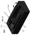
図1Aは本開示に係る回路保護デバイス100の全体図である。図1Bは図1Aの回路保護デバイス100の全体分解図である。回路保護デバイス100(例えば、ヒューズ)は、底部セクション102Bに取り付けられた上部セクション102Aを有するハウジング102を含んでもよい。底部セクション102Bは、様々な形状および寸法のうちの1つ、例えば、正方形(four-sided square)および/または長方形(four-sided rectangular)に構成されてもよい。底部セクション102Bは、当該底部セクション102B内の1つ以上の配置から延在する第1アークバリア106Aを含むことができる。上部セクション102Aおよび底部セクション102Bは、共に取り付けられたとき、オープンスペース(open space)またはキャビティ110を規定することができる。一実施態様においては、上部セクション102Aが底部セクション102Bと共に取り付けられたとき、キャビティ110はハウジング102の中央でオープンスペースの全てを含むことができる。より詳しくは、キャビティ110は幾つかのオープンスペース部分を含むように規定されてもよい。 FIG. 1A is an overall view of a
回路保護デバイス100は第1端子104Aおよび第2端子104Bを含んでもよい。第1端子104Aおよび第2端子104Bは底部セクション102Bに固定され得る。一実施態様においては、上部セクション102Aは、当該上部セクション102Aから延在する壁によって規定される第2アークバリア(図1A〜図1Bにおいて図示せず)を含んでもよい。図1Bに示すように、第1端子104Aは上部セクション104Dを含むことができ、第2端子104Bは上部セクション104Cを含むことができる。一実施態様においては、第1端子104Aおよび第2端子104Bは、底部セクション102Bに対して、スナップ留め(snapped)、型留め(molded)、ボルト留め(bolted)、摩擦嵌合(friction fitted)および/または溝内突起(tongue-in-groove)による固定が可能な、様々な種々の形状の端子のうちの1つ、例えば、C形状の端子またはL形状の端子であってもよい。例えば、一実施態様においては、第1端子104Aおよび第2端子104Bが底部セクション102Bに組み立てられるとき、第1端子104Aおよび第2端子104Bは、底部セクション102Bの受入端部(receiving end)に、凸部または水平部(tongue or horizontal portion)(例えば、上部セクション104D、104C)により、スナップ留めおよび/または嵌合留めしてもよい。 The
一実施態様においては、回路保護デバイス100はヒューズ素子112を含むことができる。ヒューズ素子112は、第1端子104Aの上部セクション104Dと第2端子104Bの上部セクション104Cとの間に位置付けられてよい。ヒューズ素子は、少なくとも1つのアークバリア、例えば、第1アークバリア106Aの上および/または下を横切るため、蛇行形状(serpentine shape)を有していてもよい。換言すると、ヒューズ素子112は、蛇行形状を有して、少なくとも1つのアークバリアを上から越えることにより、例えば底部セクション102Bにおける第1アークバリア106Aの先端108Aを上から越えることにより、少なくとも1つのアークバリア、例えば第1アークバリア106Aを横切ることができる。 In one embodiment,
ヒューズ素子112は、ニッケル、銅、錫、または、ニッケル、銅、銀、金および/または錫を含む合金もしくは混合物から構成されていてもよい。幾つかの実施例によれば、ヒューズ素子112は0.02〜5ミル(1ミル(mil)は1/1000インチである)の厚みを有していてもよい。ヒューズ素子112は、複数の幾何学的形状のうちの1つの形状で配置される金属材料からなる本体を含んでもよい。ヒューズ素子112は、第1端子104Aおよび第2端子104Bに取り付けられてもよいし、かつ/または第1端子104Aおよび第2端子104Bと接触してもよい。ヒューズ素子112は、第1端子104Aおよび第2端子104Bそれぞれの上部セクション104D、104Cの両方の上に配置され、かつ当該両方に対して電気的に接続または結合してもよい。換言すると、ヒューズ素子112の両端部は、第1端子104Aおよび第2端子104Bの両方の上に配置され、かつ当該両方に対して電気的に接続または結合してもよい。ヒューズ素子112は少なくとも1つのアークバリア、例えば第1アークバリア106Aを横切ることができる。ヒューズ素子112は、過電流条件(状態)の間に、溶融(または断線もしくは分割(split))し得る。少なくとも1つのアークバリア、例えば第1アークバリア106Aはヒューズ素子112の作動(activation)/溶融によりアーク放電を防止または低減するように構成することができる。 The
図1Bに示すように、上部セクション102Aは、より正確に、ハウジングユニット102の配置組み立てを案内し、位置付けかつ固定するために、1つ以上のポジショニング・ガイド(positioning guide)114(例えばウェルド・エクステンジョン(weld extension))を含むことができる。 As shown in FIG. 1B, the
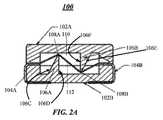
図2Aは本開示の回路保護デバイス100の一例の断面図である。回路保護デバイス100は内蔵式アーク・クエンチャーを備えたエア・スプリット・ヒューズにおけるワイヤであってもよい。示されるように、回路保護デバイス100は、底部セクション102Bに取り付けられた上部セクション102Aを含むハウジングを含んでもよい。回路保護デバイス100は、底部セクション102Bから延在する傾斜側壁部分(sloped sidewall portion)106Cおよび鉛直側壁部分(vertical sidewall portion)106Dにより規定される第1アークバリア106Aを含んでもよい。回路保護デバイス100はまた、上部セクション102Aからキャビティ110に向かって下方に延在する傾斜側壁部分106Eおよび鉛直側壁部分106Fを有する第2アークバリア106Bも含んでよい。上部セクション102Aおよび底部セクション102Bは共に取り付けられて、窪みまたはキャビティ110を規定し、当該窪みまたはキャビティは、第1アークバリア106Aと第2アークバリア106Bとの間のスペースを含むことができる。 FIG. 2A is a cross-sectional view of an example of the
図2Aで理解できるように、ハウジング102の上部分102Aはハウジング102の略上半分を形成することができ、ハウジング102の底部分102Bはハウジング102の略下半分を形成することができる。 As can be seen in FIG. 2A, the
例えば、第1アークバリア106Aは、傾斜側壁部分106Cおよび当該傾斜側壁部分106Cと反対側の鉛直側壁部分106Dによって規定され、傾斜側壁部分106Cおよび/または先端108Aはヒューズ素子112の第1部分を支持することができる。第2アークバリア106Bは、傾斜側壁部分106Eおよび当該傾斜側壁部分106Eと反対側の鉛直側壁部分106Fによって規定され、傾斜側壁部分106Eおよび/または先端108Bはヒューズ素子112の第2部分を支持することができる。 For example, the
一実施態様においては、第1アークバリア106Aは底部セクション102Bに成形されてもよい(し、またはその一部として形成されてもよい)。第2アークバリア106Bは上部セクション102Aに成形されてもよい(し、またはその一部として形成されてもよい)。第1アークバリア106Aおよび第2アークバリア106Bは、350ボルト直流(volts direct current)(VDC)より大きな高破壊容量をもたらす。一実施態様においては、第1アークバリア106Aおよび第2アークバリア106Bは、回路保護デバイス100の作動時(例えば、過電流条件に応答してヒューズ素子112が溶融または断線するとき)に、アーク放電を防止または低減するように構成することができる。 In one embodiment, the
一実施態様においては、ヒューズ素子112は、当該ヒューズ素子112の両端部分が同一平面上にあって、かつ第1端子104Aおよび第2端子104Bと結合および接続していてもよい。一実施態様においては、ヒューズ素子112の全部または一部が蛇行形状または蛇行状形状(serpentine-like shape)であってもよい。ヒューズ素子112は、第1端子104Aと接続し、第1アークバリア106Aおよび第2アークバリア106Bの向こう側まで、第1アークバリア106Aおよび第2アークバリア106Bに沿って、横切ってもよく、例えば、一方の上(例えば106Aの上)および他方の下(例えば106Bの下)を異なる水準で横切って、第1端子104Aを第2端子104Bに接続してもよい。換言すると、ヒューズ素子112は、蛇行形状を有して、底部セクション102Bの第1アークバリア106Aを上から越え、かつ上部セクション102Aの第2アークバリア106Bを下からくぐってもよい。ヒューズ素子112は少なくとも以下の3つのセクションを含んでもよい:第1アークバリア106Aから、上部セクション102Aおよび底部セクション102Bが接触または接合するハウジング102の縁部(edge)までの1つのセクション;第1アークバリア106Aと第2アークバリア106Bとの間の第2セクション;および第2アークバリア106Bと、上部セクション102Aおよび底部セクション102Bが接触または接合するハウジング102の反対側縁部との間の第3セクション。一般的には、ヒューズ素子112は、第1端子104Aと第2端子104Bとの間を横切りながら、第1アークバリア106Aおよび第2アークバリア106Bそれぞれの向こう側まで通り抜けるように、あらゆる方法で成形され得る。 In one embodiment, the
一実施態様においては、ヒューズ素子112において、第1アークバリア106Aの先端108Aおよび第2アークバリア106Bの先端108Bにより支持される部分は、様々な幾何学的形状のうちの1つの形状、例えば曲線形状または三角形状であってもよい。例えば、第1アークバリア106Aは底部セクション102Bから上方向に延在する傾斜側壁106Cにより規定されながら、ヒューズ素子112は第1端子104Aから水平方向に横切った後、進行方向を斜め上方向に変え、第1アークバリア106Aを越える。ヒューズ素子112において先端108Aにより支持される部分は、ヒューズ素子112を方向転換させるように、三角形状であってもよい。ヒューズ素子112はまた、キャビティ110の一部を、斜め下方向に横切り、バリア106Bをくぐる。ヒューズ素子112において先端108Bにより支持される部分は、ヒューズ素子112を方向転換させるように、三角形状であってもよい。ヒューズ素子112は先端108Bで方向を転換し、斜め上方向に横切った後、第2端子104Bまで水平方向に横切る。ヒューズ素子112は、第1端子104Aと接続および結合される一端部および第2端子104Bと接続および結合される反対側の端部を同一平面上とすることができる。また、ヒューズ素子112は、第1アークバリア106Aの先端108Aと接続されてもよいし、かつ/または当該先端108Aの上に載っていてもよい。かつ/または、ヒューズ素子112は、第2アークバリア106Bの先端108Bと接続されてもよいし、かつ/または当該先端108Aの上に載っていてもよい。 In one embodiment, in the
キャビティ110は、例えば、第1チャンバー、第2チャンバーおよび/または第3チャンバーなどの幾つかのチャンバー(例えば部品)を含むように規定されてもよい。第1チャンバーは、上部セクション102Aおよび底部セクション102Bの一端部と第1アークバリア106Aとの間のキャビティ110のオープン・スペースであってもよい。第2チャンバーは、第1アークバリア106Aと第2アークバリア106Bとの間のキャビティ110のオープン・スペースとして規定されてもよい。第3チャンバーは、第2アークバリア106Bと、上部セクション102Aおよび底部セクション102Bの他端部との間のキャビティ110のオープン・スペースとして規定されてもよい。 The
ヒューズ素子112はキャビティ110の全部または一部を通して横切ることができる。一実施態様においては、キャビティ110はヒューズ素子112の全部または一部が空気により包囲されるように設けることができる。また、アーク放電を防止、低減または最小化するために、キャビティ110の全部または一部に、アーク放電の可能性を最小化する充填材を充填してもよい。当該充填材は、例えば、アーク抑制用材料であり得る。アーク抑制用材料は、ヒューズ素子112の両端部間および/または両端子104A、104B間でアーク放電を防止するに際して、少なくとも1つのアークバリア、例えば第1アークバリア106Aの補助をしてもよい。アーク抑制用材料は、無機系、乾燥型、粒状、非導電性の材料であり得る。具体例として、例えば、石英砂、シリカ、セラミック粉体、および硫酸カルシウムが挙げられる。このような材料は、ハウジングを閉じる前に、ハウジングに設置されることが好ましい。換言すれば、アーク抑制用材料は、底部セクション102Bが上部セクション102Aに接続されるとき、キャビティ110に注入されてもよい。一例として、キャビティ110の第1部分および第3部分はアーク抑制用材料を含んでもよい。別の形態においては、キャビティ110の第2部分および/または第3部分はアーク抑制用材料を含んでもよい。 The
図2Bは、本開示に係る回路保護デバイス100のハウジングユニット102の寸法の一例を示す上面図である。当該ハウジングユニット102は様々な幾何学的形状および寸法を有するもののうちの1つであること、および図2Bは一実施態様のハウジングユニット102の長さ寸法および幅寸法の一例を示すことに注意するべきである。図2Bは図2Aに示す回路保護デバイスの上面図を示す。特に図2Bは、ハウジングユニット102の上部セクション102Aを見下ろした図を示す。要素220は、図2Aで表される図の方向を示す。図2Bで示される寸法の一例はミリメーター(mm)単位で提供することができる。 FIG. 2B is a top view illustrating an example of the dimensions of the
図3Aは、本開示に係る回路保護デバイス100の上部セクション102Aの全体図である。上部セクション102Aは、ヒューズ素子112がキャビティ110ならびに第1アークバリア106Aおよび第2アークバリア106Bを横切ることを可能にするための、様々な内部設計および構造を含んでもよい。また、上部セクション102Aの各側は、勾配面(ramped face)および/または傾斜部(sloped portion)175Aを有する少なくとも1つの二次的チャンバー(secondary chamber)175を含んでもよい(図示することを目的として、このような二次的チャンバー175のうち1つのみ示されているが、さらなる二次的チャンバーを上部セクション102Aの反対側端部に位置付けることができる)。一実施態様においては、当該少なくとも1つの二次的チャンバー175は傾斜した勾配状キャビティを規定し、はんだレリーフ(solder relief)を提供する。各二次的チャンバー175は上部セクション102Aの各反対側端部に設けられてもよい。一実施態様においては、上部セクション102Aを底部セクション102Bに取り付けると、少なくとも1つの二次的チャンバー175は直接的に、端子104Aまたは104Bの一方の上方部(例えば、上部セクション104Cまたは104D)の上に配置され得る。 FIG. 3A is a general view of the
上部セクション102Aはまた、ハウジングユニット102の底部セクション102Bへの上部セクション102Aの配置を促進するために、1つ以上のポジショニング・ガイド114、116(例えば「ウェルド・エクステンジョン」)を含むことができる。上部セクション102Aおよび底部セクション102Bは共同でハウジングユニット102を形成することに注意するべきである。
図3Bは、本開示に係る回路保護デバイス100の底部セクション102Bの全体図である。底部セクション102Bはヒューズ素子112を受け入れるために備わっている。ヒューズ素子112は、ハウジングユニット102の上部セクション102Aおよび底部セクション102B内に取り付けられ、かつ複数の幾何学的形状のうちの1つの形状で配置される金属材料からなる本体を含んでもよく、第1アークバリア106Aの上および/または向こう側まで延在し、かつ第2アークバリア106Bの下および/または向こう側まで延在している。第1端子104Aおよび第2端子104Bは、あらゆる適切な導電性材料、例えば銅または錫から形成されてもよい。導電性材料は所望の溶融特性(fusing characteristics)および/または耐久性に基づいて決定されてもよい。 FIG. 3B is a general view of the
ヒューズ素子112は第1端子104Aおよび第2端子104Bに、例えばはんだ付けによって電気的に接続されてもよい。図3Bに示されるように、例えば、ヒューズ素子112の第1端部は第1端子104Aに接続されてもよく、ヒューズ素子112の第2端部は第2端子104Bに接続されてもよい。ヒューズ素子112の少なくとも1つ以上の部分(例えば両端部)は第1端子104Aおよび第2端子104Bと同一平面上にあってもよい。図3Bに示されるように、第1端子104Aおよび第2端子104Bの少なくとも一部は底部セクション102Bを回り込むように配置され、包み込んでいる。ヒューズ素子112は、第1端子104Aおよび第2端子104Bの上部における様々な位置のうちの1つの位置、例えば中央位置に配置され、そこに、はんだ付けされている。ヒューズ素子112の両端部の少なくとも一部を第1端子104Aおよび第2端子104Bにより支持し、ヒューズ素子112の別の部分にキャビティ110を横切らせて空気による包囲をさせながら、屈曲または下垂を防止してもよい。 The
図3Cは、本開示に係る回路保護デバイス100の上部セクション102Aにおけるポジショニング・ガイドおよびウェルド・エクステンジョン114の全体図である。ポジショニング・ガイド114、116は超音波接合(ultrasonic welding)のためのエネルギー・ディレクター(energy director)として機能し得る。一実施態様においては、エネルギー・ディレクター(例えば、ポジショニング・ディレクター114,116)は突起(ridge)または隆起(bump)形態の材料であってよく、周辺の表面より少し上方に延在し、上部セクション102Aの領域を囲み、接合されるべき1つまたは複数の表面と接触する。エネルギー・ディレクターは上部セクション102Aの表面に成形されてもよい。上部セクション102Aは、超音波接合される上部セクション102Aの表面と直接的な接触状態にあってもよい。超音波接合工程の間、ポジショニング・ガイド114,116はまず、上部セクション102Aと底部セクション102Bとの間で生じる摩擦の結果として融解または溶融し、超音波により接合される。一実施態様においては、融解または溶融は、上部セクション102Aおよび底部セクション102Bにおけるポジショニング・ガイド114,116の位置に近いところで起こり得る。結合および冷却されると、このような位置で固化が起こり、底部セクション102Bを上部セクション102Aにシールすることができる。 FIG. 3C is a general view of the positioning guide and
ポジショニング・ガイド114および116は取付用延在部(mounting extension)として考えることができる。取付用延在部114および116は、組立時に、底部セクション102Bへの上部セクション102Aの配置および整列を促進し得る。さらに、底部セクション102Bは窪み部(recessed portion)320を含み得る。窪み部320は底部セクション102Bの対向する側部側に位置付けられ得る。窪み部320は底部セクション102Bの内周に位置付けられ得る。窪み部320は、図3Aおよび図3Bに示すように、上部セクション102Aを底部セクション102Bの上に位置付けたとき、取付用延在部114および116の部分と一致し、協調するように、位置付けられ、かつ成形され得る。窪み部320および取付用延在部114および116は共に、シール前において、上部セクション102Aと底部セクション102Bとの位置合わせされた確実な嵌合を確保することができる。 Positioning guides 114 and 116 can be considered as mounting extensions. The mounting
図4は、本開示に係る回路保護デバイス100の一例における複数の部品の全体分解図である。上部分またはカバー102Aはウルトラミド(Ultramid)TKR4365G5を含む様々な材料から形成することができる。下部分102Bもまた、ウルトラミド(Ultramid)TKR4365G5を含む様々な材料から形成することができる。端子104Aおよび104Bは、一例として、錫めっき銅(tin platted copper)で形成することができる。ヒューズ素子は、一実施態様においては、銅合金から形成することができる。 FIG. 4 is an overall exploded view of a plurality of components in an example of the
一実施態様においては、底部セクション102Bは上部セクション102Aの真下に配置される。ヒューズ素子は、底部セクション102Bの上であって、上部セクション102Aの下に配置される。底部セクション102Bの両側においては、第1端子104Aおよび第2端子104Bが固定される。 In one embodiment, the
一実施態様においては、第1端子104Aおよび第2端子104Bはそれぞれ、様々な幾何学的形状のうちの1つ、例えば、C形状であってもよい。一実施態様においては、C形状の第1端子104Aおよび第2端子104Bは、底部セクション102Bの反対位置の両端部を包み込むことができる。例えば、第1端子104Aおよび第2端子104Bは、C形状を有してもよく、底部セクション102Bの上縁部(top edge)まで延在することができるし、かつ/または底部セクション102Bの低位縁部(lower edge)を包み込むことができる。第1端子104Aは上縁部104Dを有してもよく、当該上縁部104Dは屈曲し、延在し、かつ/またはヒューズ素子112を受け入れる底部セクション102Bの上縁部を包み込んでもよい。上縁部104Dはその後、底部セクション102Bに固定され、結合され、かつ/または接続される。第1端子104Aはまた、底縁部(bottom edge)104Eを有してもよい。底縁部104Eは、底部セクション102Bに接続することができるし、かつ/または固定することもできる。底縁部104Eは、底部セクション102Bの一部に掛かっていてもよく、かつ/または屈曲し、延在し、かつ/または底部セクション102Bの底縁部を包み込んでもよい。一実施態様においては、上縁部104Dおよび底縁部104Eは第1端子104Aの一部に対して直角であってもよく、このため実質的にC形状を形成し、底部セクション102Bの少なくとも一部に固定されてもよい。上縁部104Dおよび底縁部104Eは、底部セクション102Bを包み込む第1端子104Aの一部分により接続されてよい。 In one embodiment, the
一実施態様においては、第2端子104Bは上縁部104Cを有してもよく、当該上縁部104Cは屈曲し、延在し、かつヒューズ素子112を受け入れる底部セクション102Bの上縁部を包み込んでもよい。上縁部104Cはその後、底部セクション102Bに固定され、結合され、かつ/または接続される。第2端子104Bはまた、底縁部(bottom edge)104Fを有してもよい。底縁部104Fは、底部セクション102Bに接続され、かつ/または固定される。底縁部104Fは、底部セクション102Bの一部に掛かっていてもよく、かつ/または屈曲し、延在し、かつ底部セクション102Bの底縁部を包み込んでもよい。一実施態様においては、上縁部104Cおよび底縁部104Fは第2端子104Bの一部に対して直角であってもよく、このため実質的にC形状を形成し、底部セクション102Bの少なくとも一部に固定されてもよい。上縁部104Cおよび底縁部104Fは、底部セクション102Bを包み込む第2端子104Bの一部分により接続されてよい。組み立て後、上縁部104Cおよび104Dは、ハウジング102の上部分102Aと下部分102Bとの間に位置付けられてもよい。 In one embodiment, the
一実施態様においては、回路保護デバイス100は2つの部品、例えば、カバー(例えば上部セクション102A)およびハウジング(例えば底部セクション102B)で組み上げられてもよい。第1端子104Aおよび第2端子104Bが接続された後、ヒューズ素子112が接続され、当該ヒューズを閉じることが必要である。回路保護デバイス100の2つの部品(例えば上部セクション102Aおよび底部セクション102B)は多くの方法で閉じてもよい。 In one embodiment,
一実施態様においては、プラスチック部品を用いる場合、組立は、底部セクション102Bの上に上部セクション102Aを設置する工程、および上部セクション102Aを底部セクション102Bに超音波接合によりシールする工程を含んでもよい。別の方法では、例えば、ポリプロピレン「接合」ビードのビードを、部品間の分割線に流し入れることにより、複数の部品(例えば、上部セクション102Aおよび底部セクション102B)を共にプラスチック接合(plastic welding)する工程を含むことができる。ポジショニング・ガイド114(図1〜3参照)は、超音波接合のためのエネルギー・ディレクターとして機能し得る。複数の部品の連結のために接着剤を用いてもよく、または溶剤結合の技術を用いてもよい。溶剤結合の技術では、両部品を溶解する溶剤を、その一方または他方または両方に配置し、当該部品を共に加圧する。上記した幾つかの実施態様において示すように、当該部品には、摩擦嵌合機構(例えば、突起−溝適合機構(matching tongue-and groove features))またはスナップ式嵌合機構(例えば、雄雌スナップ式嵌合部(male and female snap-fit portions))が備わっていてもよい。あらゆる適切な手段を用いて、閉じて、固定してもよい。 In one embodiment, where a plastic part is used, the assembly may include the steps of placing the
図4でより一層、明らかに示すように、底部セクション102Bは、第1端子104Aおよび第2端子104Bを受けるための突起−溝適合機構またはスナップ式嵌合機構として設計されている少なくとも1つの受け手段(receiving means)140A/140Bを含むことができる。換言すると、底部セクションの受け手段は、第1端子104Aの第1セクション(first section)104Dおよび第2端子104Bの第1セクション104Cを受けるための突起−溝適合機構および/またはスナップ式嵌合機構であり得る。 As is even more clearly shown in FIG. 4, the
一実施態様においては、底部セクション102Bおよび上部セクション102Aは、内壁を有し、かつ当該内壁および外壁内にあり、第1端子104Aおよび第2端子104Bを受けるための開口部を有する成形プラスチック部品であってもよい。 In one embodiment,
一実施態様においてはまた、上部セクション102Aおよび底部セクション102Bは、様々なポリアミド、例えばウルトラミドTKR4365G5から製造され得ることにも注意するべきである。第1端子104Aおよび第2端子104Bは、様々な導電性材料のうちの1つ、例えば錫めっき銅から製造されてもよい。さらにヒューズ素子112は銅合金から製造されてもよい。 It should also be noted that in one embodiment, the
図5は、本開示に係る回路保護デバイスの操作(operation)方法500における一実施態様のフローチャートを示す。操作方法500は、本明細書中で説明する回路保護デバイス100に適用することができる。操作方法500はブロック502で開始する。操作方法500はブロック504に移る。ブロック504においては、少なくとも1つのアークバリア(例えば、第1アークバリア106Aおよび/または第2アークバリア106B)の上および/または下に配置されるヒューズ素子は、ヒューズにおける特定の故障条件の発生により、溶融または断線または分割もしくはさもなければ作動する。ブロック506においては、操作方法500は、少なくとも1つのアークバリア(例えば、第1アークバリア106Aおよび/または第2アークバリア106B)により、ヒューズの開口部の間で形成されるアーク放電を防止および/または低減する。ブロック508においては、操作方法500は終了してもよい。 FIG. 5 shows a flowchart of an embodiment of a
図6は、本開示に係る回路保護デバイスの操作方法における一実施態様のフローチャートを示す。操作方法600は、本明細書中で説明する回路保護デバイス100に適用することができる。操作方法600はブロック602で開始する。操作方法600はブロック604に移る。ブロック604においては、底部セクションに取り付けられた上部セクションを有するハウジングを含むブロック604のヒューズと直列で、電気デバイスを電力源に接続する。ヒューズは、底部セクションから延在する壁部により規定される第1アークバリアをさらに含むことができる。第2アークバリアは上部セクションから延在する壁部により規定されることができ、上部セクションおよび底部セクションを共に取り付けることにより、第2アークバリアから一定の距離で離れている第1アークバリアとの間に窪みまたはキャビティを規定する。第1端子および第2端子は底部セクションに固定されている。ヒューズ素子は、ハウジングの上部セクションおよび底部セクション(例えば、底部ホルダーまたは底部ハウジング)の中で取り付けられる複数の幾何学的形状のうちの1つの形状で配置される金属材料の本体を含み、第1アークバリアおよび第2アークバリアを通じて延在しつつ、第1端子および第2端子に接続される。第1アークバリアおよび第2アークバリアは、ヒューズの作動時にアーク放電に耐えるように構成されている。操作方法600は、ブロック606において、ヒューズ素子に両端子間を蛇行経路で横切らせ、かつ第1アークバリアおよび第2アークバリアを支持ビーム(support beams)として用いることにより、ヒューズ素子の両端部を特定の最小の距離で離し、第1アークバリアから第2アークバリアまで延在するヒューズ素子の一部を空気に包囲させる。ブロック608においては、操作方法600は、第1アークバリアおよび第2アークバリアにより、ヒューズ素子の両端部間に非導電性アークバリアを提供して、第1アークバリアおよび第2アークバリアがヒューズ素子の直接路(direct path)を完全に遮断することにより、ヒューズ素子の両端部間でアーク放電を防止する。ブロック610においては、操作方法600は、ブロック610で過電流条件が生じると、ヒューズ素子の溶融(または断線または分割)によりヒューズを開く。ブロック612においては、操作方法600は終了してもよい。 FIG. 6 shows a flowchart of an embodiment of a method of operating a circuit protection device according to the present disclosure. The method of
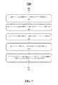
図7は、本開示に係る回路保護デバイスの製造方法700における一実施態様のフローチャートを示す。一実施態様においては、製造方法700を用いて回路保護デバイス100を形成してもよい。製造方法700はブロック702で開始する。製造方法700はブロック704に移る。ブロック704においては、上部セクションおよび底部セクションを有するハウジングを提供する。ブロック706においては、底部セクションから延在する壁部により規定される第1アークバリアを提供する。ブロック708においては、上部セクションから延在する壁部により規定される第2アークバリアを提供し、上部セクションおよび底部セクションを共に取り付けることにより、第2アークバリアから一定の距離で離れている第1アークバリアとの間に窪みまたはキャビティを規定する。ブロック710においては、底部セクションに固定されている第1端子および第2端子を提供する。ブロック712においては、ハウジングの上部セクションおよび底部セクションの中で取り付けられる複数の幾何学的形状のうちの1つの形状で配置される金属材料の本体を含むヒューズ素子を提供する。ヒューズ素子は、第1アークバリアおよび第2アークバリアを通じて延在しつつ、第1端子および第2端子に接続されることができ、第1アークバリアおよび第2アークバリアは、ヒューズの作動時にアーク放電に耐えるように構成されており、このため、過電流条件が生じると、ヒューズ素子は溶融する。ブロック712においては、ヒューズ素子は第1端子および第2端子にはんだ付けすることができる。その後、ハウジングの上部セクションおよび底部セクションは(例えば、当該2つの部品を共にシールすることにより)取り付けることができる。ブロック714においては、製造方法700は終了してもよい。 FIG. 7 shows a flowchart of an embodiment of a
本開示について特定の実施態様を参照しながら説明したが、添付の特許請求の範囲で規定されるように、本開示の分野および範囲から逸脱しない限り、説明された実施態様に対して多くの改良、変形および変更が可能である。従って、本開示は、説明された実施態様に限定されるものではなく、以下の特許請求の範囲の用語により規定される最大限の範囲および同等の範囲を有することが意図されている。 Although the present disclosure has been described with reference to particular embodiments, many modifications may be made to the described embodiments without departing from the field and scope of the present disclosure as defined in the appended claims. , Variations and modifications are possible. Accordingly, the present disclosure is not intended to be limited to the described embodiments, but is intended to have the full scope and equivalent scope defined by the terms of the following claims.
本開示の要約書は、技術的な開示の本質を読み手に迅速に解明させるために提供されていることを強調する。要約書は、特許請求の範囲の意味内容の範囲を解釈または限定するために使用されるものではないとの理解のもとで提出されている。さらに、上記した詳細な説明においては、様々な特徴は、本開示の簡素化を目的として単一の実施態様にまとめられることを理解することができる。本開示の方法は、特許請求の範囲の実施態様が各請求項で明示的に言及された特徴よりも多くの特徴を必要とするという意図の通りに解釈されるべきではない。むしろ、以下の特許請求の範囲が示す通りに、発明の主題事項は、開示された単一の実施態様の全ての特徴よりも少ない。従って、以下の特許請求の範囲は、それ自体、別の一実施態様として存在する各請求項とともに、本明細書中、詳細な説明に組み込まれるものとする。添付の特許請求の範囲においては、「含有する(including)」および「in which」という用語はそれぞれ、平易な英語の同義語「含む(comprising)」および「wherein」として使用されている。さらに、「第1」、「第2」および「第3」などの用語は、標識として使用されているだけで、物品に数的な要件を付与することを意図するものではない。 It is emphasized that the abstract of the present disclosure is provided to allow the reader to quickly understand the nature of the technical disclosure. The abstract is submitted with the understanding that it will not be used to interpret or limit the scope of the claimed subject matter. Moreover, in the foregoing Detailed Description, it can be understood that various features are grouped together in a single embodiment for the purpose of streamlining the disclosure. The methods of the present disclosure are not to be construed as meaning that the embodiments of the claims require more features than those explicitly recited in each claim. Rather, as the following claims reflect, inventive subject matter lies in less than all features of a single disclosed embodiment. Thus, the following claims are hereby incorporated into the Detailed Description, with each claim standing on its own as a separate embodiment. In the appended claims, the terms "including" and "in which" are used as the plain English synonyms "comprising" and "wherein," respectively. Furthermore, terms such as "first", "second" and "third" are only used as signs, and are not intended to give the article numerical requirements.
上記で説明したことの中には、開示された構造物についての幾つかの具体例が含まれる。複数の要素および/または手段について考えられる全ての組み合わせを説明することは、もちろん不可能であるが、当業者は、多くのさらなる組み合わせおよび変形が可能であることを理解するだろう。従って、当該新規な構造物は、添付の特許請求の範囲の目的および範囲内にある全ての変更、変形およびバリエーションを包含することを意図するものである。 Among the things described above, some specific examples of the disclosed structure are included. While it is of course not possible to describe every conceivable combination of elements and / or means, one skilled in the art will appreciate that many further combinations and variations are possible. Accordingly, the novel structures are intended to embrace all such alterations, modifications and variations that fall within the spirit and scope of the appended claims.
Claims (19)
Translated fromJapanese前記底部セクションから前記キャビティに延在する第1アークバリア;
前記上部セクションから前記キャビティに延在する第2アークバリア;
前記底部セクションに固定されている第1端子および第2端子;ならびに
前記キャビティ内に取り付けられ、かつ前記第1端子および前記第2端子に接続されているヒューズ素子であって、前記第1アークバリアおよび前記第2アークバリアを横切るヒューズ素子
を含むヒューズであって、
前記第1アークバリアおよび前記第2アークバリアは前記ヒューズの作動時にアーク放電に耐え、前記ヒューズ素子は過電流条件が生じた時に溶融し、
前記第1端子および前記第2端子の各々はその両側に形成された溝を有し、
前記ハウジングの前記底部セクションはその上縁部に形成された突起部を含み、該突起部は前記溝内に配置されており、
前記第1アークバリアは傾斜側壁および鉛直側壁により規定され、前記第1アークバリアの先端は前記ヒューズ素子の一部を支持しており、前記第2アークバリアは傾斜側壁および鉛直側壁により規定され、前記第2アークバリアの先端は前記ヒューズ素子の一部を支持している、ヒューズ。A housing having a top section attached to the bottom section and defining a cavity therein;
A first arc barrier extending from the bottom section to the cavity;
A second arc barrier extending from the upper section to the cavity;
First and second terminals fixed to the bottom section; and fuse elements mounted in the cavity and connected to the first and second terminals, the first arc barrier And a fuse element across the second arc barrier, the fuse comprising:
The first and second arc barriers withstand arcing when the fuse is activated, and the fuse element melts when an over-current condition occurs,
Each of the first terminal and the second terminal has a groove formed on both sides thereof,
The bottom section of the housing includes a projection formed on the upper edge thereof, the projection being disposed in the groove;
The first arc barrier is defined by an inclined side wall and a vertical side wall, the tip of the first arc barrier supports a part of the fuse element, and the second arc barrier is defined by an inclined side wall and a vertical side wall. A tip of the second arc barrier supports a portion of the fuse element .
前記底部セクションの各端部に固定されている第1端子および第2端子であって、各端子の第1部分は前記底部セクションの内側に延在し、各端子の第2部分は前記底部セクションの外側を包み込んでいる第1端子および第2端子;
前記底部セクションから延在する第1アークバリアおよび前記上部セクションから延在する第2アークバリア;ならびに
前記第1端子と第2端子との間で接続されるヒューズ素子であって、該ヒューズ素子は支持体としての前記第1アークバリアおよび前記第2アークバリアと接触している、ヒューズ素子
を含むヒューズであって、
前記ヒューズ素子の一部は前記第1アークバリアから前記第2アークバリアまで延在し、空気により包囲されており、
前記第1端子および前記第2端子の各々はその両側に形成された溝を有し、
前記底部セクションはその上縁部に形成された突起部を含み、該突起部は前記溝内に配置されており、
前記第1アークバリアは傾斜側壁および鉛直側壁により規定され、前記第1アークバリアの先端は前記ヒューズ素子の一部を支持しており、前記第2アークバリアは傾斜側壁および鉛直側壁により規定され、前記第2アークバリアの先端は前記ヒューズ素子の一部を支持している、ヒューズ。A housing having a bottom section and a top section;
First and second terminals secured to each end of the bottom section, wherein a first portion of each terminal extends inside the bottom section and a second portion of each terminal is the bottom section First and second terminals encasing the outside of the
A first arc barrier extending from the bottom section and a second arc barrier extending from the top section; and a fuse element connected between the first terminal and the second terminal, the fuse element comprising: A fuse including a fuse element in contact with the first arc barrier as a support and the second arc barrier,
A portion of the fuse element extends from the first arc barrier to the second arc barrier and is surrounded by air;
Each of the first terminal and the second terminal has a groove formed on both sides thereof,
The bottom section includes a projection formed on the upper edge thereof, the projection being disposed in the groove;
The first arc barrier is defined by an inclined side wall and a vertical side wall, the tip of the first arc barrier supports a part of the fuse element, and the second arc barrier is defined by an inclined side wall and a vertical side wall. A tip of the second arc barrier supports a portion of the fuse element .
前記ハウジングの上部分;
前記ハウジングの底部分の内側表面から上方に延在する第1アークバリア;
前記ハウジングの上部分の内側表面から下方に延在する第2アークバリア;
前記ハウジングの前記上部分と前記底部分との間に形成されるキャビティであって、該キャビティ内に前記第1アークバリアおよび第2アークバリアが位置付けられる、キャビティ;
前記ハウジングの前記底部分の第1端部を包み込む第1端子であって、該第1端子は上方端子部分を含み、該上方端子部分は前記ハウジングの前記底部分の前記第1端部に形成された第1スロットに嵌合する形状となっている、第1端子;
前記ハウジングの前記底部分の第2端部を包み込む第2端子であって、該第2端子は上方端子部分を含み、該上方端子部分は前記ハウジングの前記底部分の前記第2端部に形成された第2スロットに嵌合する形状となっている、第2端子;ならびに
前記第1端子の前記上方端子部分および前記第2端子の前記上方端子部分に結合されるヒューズ素子であって、該ヒューズ素子は、前記第1アークバリアの上および前記第2アークバリアの下に位置付けられるヒューズ素子
を含む装置であって、
前記第1端子および第2端子の前記上方端子部分は前記ハウジングの上部分と底部分との間に位置付けられ、前記ハウジングの上部分は前記ハウジングの略上半分を形成し、前記ハウジングの底部分は前記ハウジングの略下半分を形成し、
前記第1アークバリアは傾斜側壁および鉛直側壁により規定され、前記第1アークバリアの先端は前記ヒューズ素子の一部を支持しており、前記第2アークバリアは傾斜側壁および鉛直側壁により規定され、前記第2アークバリアの先端は前記ヒューズ素子の一部を支持している、装置。Bottom portion of the housing;
The upper part of the housing;
A first arc barrier extending upwardly from an inner surface of a bottom portion of the housing;
A second arc barrier extending downwardly from an inner surface of the upper portion of the housing;
A cavity formed between the top portion and the bottom portion of the housing, in which the first and second arc barriers are located;
A first terminal enclosing a first end of the bottom portion of the housing, the first terminal including an upper terminal portion, the upper terminal portion being formed at the first end of the bottom portion of the housing A first terminal configured to mate with the first slot;
A second terminal encasing a second end of the bottom portion of the housing, the second terminal including an upper terminal portion, the upper terminal portion being formed at the second end of the bottom portion of the housing A second terminal configured to be fitted in the second slot; and a fuse element coupled to the upper terminal portion of the first terminal and the upper terminal portion of the second terminal, The fuse element is a device including fuse elements positioned above the first arc barrier and below the second arc barrier,
The upper terminal portions of the first and second terminals are located between the upper and lower portions of the housing, the upper portion of the housing forming substantially the upper half of the housing, and the lower portion of the housing Form a substantially lower half of the housing,
The first arc barrier is defined by an inclined side wall and a vertical side wall, the tip of the first arc barrier supports a part of the fuse element, and the second arc barrier is defined by an inclined side wall and a vertical side wall. A device wherein the tip of the second arc barrier supports a portion of the fuse element .
前記第1端子の前記上方端子部分への前記ヒューズ素子の結合部に隣接して前記第1端子の前記上方端子部分の上に位置付けられる第1開放領域(first open area);および
前記第2端子の前記上方端子部分への前記ヒューズ素子の結合部に隣接して前記第2端子の前記上方端子部分の上に位置付けられる第2開放領域(second open area)
をさらに含む、請求項17に記載の装置。The upper portion of the housing is
A first open area positioned above the upper terminal portion of the first terminal adjacent to the junction of the fuse element to the upper terminal portion of the first terminal; and the second terminal A second open area positioned above the upper terminal portion of the second terminal adjacent to the junction of the fuse element to the upper terminal portion of the second terminal
The apparatus of claim 17, further comprising:
前記ハウジングの前記底部分はその上縁部に形成された突起部を含み、該突起部は前記溝内に配置される、請求項17または18に記載の装置。Each of the first terminal and the second terminal has a groove formed on both sides thereof,
19. A device according to claim 17 or 18, wherein the bottom portion of the housing comprises a projection formed on its upper edge, the projection being arranged in the groove.
Applications Claiming Priority (5)
| Application Number | Priority Date | Filing Date | Title |
|---|---|---|---|
| US201562106378P | 2015-01-22 | 2015-01-22 | |
| US62/106,378 | 2015-01-22 | ||
| US15/003,364US9824842B2 (en) | 2015-01-22 | 2016-01-21 | Wire in air split fuse with built-in arc quencher |
| US15/003,364 | 2016-01-21 | ||
| PCT/US2016/014421WO2016118800A1 (en) | 2015-01-22 | 2016-01-22 | Wire in air split fuse with built-in arc quencher |
Publications (2)
| Publication Number | Publication Date |
|---|---|
| JP2018503235A JP2018503235A (en) | 2018-02-01 |
| JP6537619B2true JP6537619B2 (en) | 2019-07-03 |
Family
ID=56417772
Family Applications (1)
| Application Number | Title | Priority Date | Filing Date |
|---|---|---|---|
| JP2017538642AExpired - Fee RelatedJP6537619B2 (en) | 2015-01-22 | 2016-01-22 | Wires in air split fuses with built-in arc quencher |
Country Status (6)
| Country | Link |
|---|---|
| US (1) | US9824842B2 (en) |
| EP (1) | EP3248205B1 (en) |
| JP (1) | JP6537619B2 (en) |
| KR (1) | KR101889673B1 (en) |
| CN (1) | CN107112171A (en) |
| WO (1) | WO2016118800A1 (en) |
Families Citing this family (19)
| Publication number | Priority date | Publication date | Assignee | Title |
|---|---|---|---|---|
| US10141150B2 (en)* | 2016-02-17 | 2018-11-27 | Littelfuse, Inc. | High current one-piece fuse element and split body |
| CN106409629A (en)* | 2016-09-28 | 2017-02-15 | 深圳路科技有限公司 | Fuse device and fabrication method thereof |
| US10325746B2 (en)* | 2016-11-15 | 2019-06-18 | Littelfuse, Inc. | Ventilated fuse housing |
| JP7002955B2 (en)* | 2017-02-28 | 2022-01-20 | デクセリアルズ株式会社 | Fuse element |
| US10283307B2 (en)* | 2017-04-05 | 2019-05-07 | Littelfuse, Inc. | Surface mount fuse |
| CN106997834B (en)* | 2017-05-27 | 2020-04-21 | 杨光 | Filling type high-voltage fuse and manufacturing method thereof |
| US10854413B2 (en)* | 2017-11-27 | 2020-12-01 | Conquer Electronics Co., Ltd. | Fuse line fixing structure of fuse |
| CN109192635B (en)* | 2018-10-19 | 2024-02-13 | Aem科技(苏州)股份有限公司 | Fuse and production method thereof |
| US11101093B2 (en)* | 2019-01-21 | 2021-08-24 | Littelfuse, Inc. | Fuses and methods of forming fuses |
| US10553387B1 (en)* | 2019-02-07 | 2020-02-04 | Littelfuse, Inc. | Fuse with arc-suppressing housing walls |
| CN110265275B (en)* | 2019-07-08 | 2021-10-08 | 广东中贝能源科技有限公司 | A novel filling composition for fuse |
| US11081308B2 (en)* | 2019-08-06 | 2021-08-03 | Littelfuse, Inc. | Vertical surface mount device pass-through fuse |
| IT201900018947A1 (en)* | 2019-10-16 | 2021-04-16 | Audio Ohm Di Tonani Caterina & C S R L | Electric fuse |
| FR3113180B1 (en)* | 2020-07-29 | 2022-08-05 | Mersen France Sb Sas | Fuse and associated method of manufacture |
| US11631566B2 (en)* | 2020-11-13 | 2023-04-18 | Littelfuse, Inc. | Modular high voltage fuse |
| TWI757137B (en)* | 2021-03-31 | 2022-03-01 | 功得電子工業股份有限公司 | Airtight surface mount fuse with insert cavity |
| US11251009B1 (en)* | 2021-04-07 | 2022-02-15 | Littelfuse, Inc. | Fuse housing for safe outgassing |
| DE102021002383A1 (en)* | 2021-05-05 | 2022-11-10 | Siba Fuses Gmbh | Fuse and method of making a fuse |
| CN114927392B (en)* | 2022-05-30 | 2025-08-12 | 国网江苏省电力有限公司电力科学研究院 | Fuse and AC/DC distribution network leakage protection device |
Family Cites Families (31)
| Publication number | Priority date | Publication date | Assignee | Title |
|---|---|---|---|---|
| US2734110A (en)* | 1956-02-07 | Magnetic blast fuses | ||
| US441933A (en)* | 1890-12-02 | Thermal cut-out | ||
| US480802A (en)* | 1892-08-16 | Electric fuse | ||
| US1700582A (en)* | 1925-10-02 | 1929-01-29 | Brown George Rudston | Electrical fuse block |
| US3601737A (en)* | 1969-10-09 | 1971-08-24 | Gen Electrie Co | Fuse elements for dc interruption |
| US3829808A (en)* | 1973-02-14 | 1974-08-13 | Westinghouse Electric Corp | Fuse housing construction utilizing extruded terminals and process for making same |
| JPS5921500Y2 (en)* | 1982-03-19 | 1984-06-25 | 三王株式会社 | Ultra-compact fuse with lead |
| JPS59119545U (en)* | 1983-02-02 | 1984-08-11 | 日本電信電話株式会社 | Chip-shaped fuse |
| US4608548A (en) | 1985-01-04 | 1986-08-26 | Littelfuse, Inc. | Miniature fuse |
| NL8501004A (en)* | 1985-04-04 | 1986-11-03 | Littelfuse Tracor | MELT SAFETY. |
| JPH0433631Y2 (en)* | 1988-07-15 | 1992-08-12 | ||
| NL8802872A (en)* | 1988-11-21 | 1990-06-18 | Littelfuse Tracor | MELT SAFETY. |
| US4894633A (en)* | 1988-12-12 | 1990-01-16 | American Telephone And Telegraph Company | Fuse Apparatus |
| JPH0720828Y2 (en)* | 1989-06-14 | 1995-05-15 | エス・オー・シー株式会社 | Ultra-small current fuse |
| JPH0629878Y2 (en)* | 1990-10-11 | 1994-08-10 | エス・オー・シー株式会社 | High breaking ultra small fuse |
| JP2872525B2 (en)* | 1993-04-08 | 1999-03-17 | コーア株式会社 | Circuit protection element |
| JP2717076B2 (en)* | 1995-08-30 | 1998-02-18 | エス・オー・シー株式会社 | Surface mount microminiature current fuse |
| US6407657B1 (en)* | 2000-02-03 | 2002-06-18 | Littelfuse, Inc. | Dual use fuse |
| JP2001250466A (en)* | 2000-03-03 | 2001-09-14 | Taiheiyo Seiko Kk | Fuse element and fuse mounting device |
| JP2001266733A (en)* | 2000-03-22 | 2001-09-28 | Yazaki Corp | fuse |
| JP3242095B2 (en)* | 2000-05-16 | 2001-12-25 | 矢崎総業株式会社 | fuse |
| JP2002245922A (en)* | 2001-02-19 | 2002-08-30 | Koa Corp | Surface mounting type current fuse element and method of manufacturing the current fuse element |
| DE112006002655T5 (en) | 2005-10-03 | 2008-08-14 | Littelfuse, Inc., Des Plaines | Fuse with cavity forming housing |
| JP2008052961A (en)* | 2006-08-23 | 2008-03-06 | Matsushita Electric Ind Co Ltd | Surface mount type current fuse and manufacturing method thereof |
| DE102008025917A1 (en)* | 2007-06-04 | 2009-01-08 | Littelfuse, Inc., Des Plaines | High voltage fuse |
| JP2009032489A (en)* | 2007-07-26 | 2009-02-12 | Soc Corp | Fuse |
| US8077007B2 (en)* | 2008-01-14 | 2011-12-13 | Littlelfuse, Inc. | Blade fuse |
| US9117615B2 (en) | 2010-05-17 | 2015-08-25 | Littlefuse, Inc. | Double wound fusible element and associated fuse |
| US8629749B2 (en)* | 2010-11-30 | 2014-01-14 | Hung-Chih Chiu | Fuse assembly |
| DE102010063832B4 (en)* | 2010-12-22 | 2020-08-13 | Tridonic Gmbh & Co Kg | Circuit protection, circuit board and operating circuit for lamps with the circuit protection |
| JP5566933B2 (en)* | 2011-03-23 | 2014-08-06 | 古河電気工業株式会社 | High frequency communication equipment |
- 2016
- 2016-01-21USUS15/003,364patent/US9824842B2/enactiveActive
- 2016-01-22CNCN201680004915.7Apatent/CN107112171A/enactivePending
- 2016-01-22WOPCT/US2016/014421patent/WO2016118800A1/ennot_activeCeased
- 2016-01-22KRKR1020177016662Apatent/KR101889673B1/ennot_activeExpired - Fee Related
- 2016-01-22JPJP2017538642Apatent/JP6537619B2/ennot_activeExpired - Fee Related
- 2016-01-22EPEP16740797.2Apatent/EP3248205B1/enactiveActive
Also Published As
| Publication number | Publication date |
|---|---|
| EP3248205B1 (en) | 2020-02-19 |
| EP3248205A4 (en) | 2018-08-22 |
| US9824842B2 (en) | 2017-11-21 |
| WO2016118800A1 (en) | 2016-07-28 |
| KR20170084315A (en) | 2017-07-19 |
| US20160217960A1 (en) | 2016-07-28 |
| CN107112171A (en) | 2017-08-29 |
| EP3248205A1 (en) | 2017-11-29 |
| JP2018503235A (en) | 2018-02-01 |
| KR101889673B1 (en) | 2018-08-20 |
Similar Documents
| Publication | Publication Date | Title |
|---|---|---|
| JP6537619B2 (en) | Wires in air split fuses with built-in arc quencher | |
| US10490379B2 (en) | Surface mount fuse | |
| US10937619B2 (en) | Fuse element and fuse device | |
| US10553387B1 (en) | Fuse with arc-suppressing housing walls | |
| CN109661712B (en) | Solderless surface mount fuse link | |
| JP2008300357A (en) | High-voltage fuse | |
| JPWO2002099827A1 (en) | Thermal fuse and battery using the same | |
| JP2004071264A (en) | Fuse | |
| US20250182993A1 (en) | Protection element | |
| KR20210102838A (en) | terminal bus bar | |
| JP2023512162A (en) | current limiting fuse | |
| JP2015032424A (en) | Fuse | |
| JP6363974B2 (en) | fuse | |
| KR101918156B1 (en) | Temperature resistance fuse with direct connection type spring terminal | |
| TW202333178A (en) | Electrical fuse | |
| KR101529829B1 (en) | The complex protection device of blocking the abnormal state of current and voltage | |
| US11749483B1 (en) | Fuse with compartmentalized body and parallel fuse elements | |
| KR101742215B1 (en) | Micro sub-miniature fuse manufacturing method | |
| JP6574690B2 (en) | Protective element | |
| JP2003036779A (en) | Fuse | |
| JP2016143645A (en) | Protective element | |
| JP2015018740A (en) | Fuse | |
| JPH03155018A (en) | Fuse breaker | |
| JP2002110026A (en) | Fuse structure of capacitor device | |
| HK1177047A (en) | Temperature fuse |
Legal Events
| Date | Code | Title | Description |
|---|---|---|---|
| A621 | Written request for application examination | Free format text:JAPANESE INTERMEDIATE CODE: A621 Effective date:20170921 | |
| A977 | Report on retrieval | Free format text:JAPANESE INTERMEDIATE CODE: A971007 Effective date:20180710 | |
| A131 | Notification of reasons for refusal | Free format text:JAPANESE INTERMEDIATE CODE: A131 Effective date:20180724 | |
| A521 | Request for written amendment filed | Free format text:JAPANESE INTERMEDIATE CODE: A523 Effective date:20181023 | |
| A131 | Notification of reasons for refusal | Free format text:JAPANESE INTERMEDIATE CODE: A131 Effective date:20181204 | |
| A521 | Request for written amendment filed | Free format text:JAPANESE INTERMEDIATE CODE: A523 Effective date:20190301 | |
| TRDD | Decision of grant or rejection written | ||
| A01 | Written decision to grant a patent or to grant a registration (utility model) | Free format text:JAPANESE INTERMEDIATE CODE: A01 Effective date:20190514 | |
| A61 | First payment of annual fees (during grant procedure) | Free format text:JAPANESE INTERMEDIATE CODE: A61 Effective date:20190604 | |
| R150 | Certificate of patent or registration of utility model | Ref document number:6537619 Country of ref document:JP Free format text:JAPANESE INTERMEDIATE CODE: R150 | |
| R250 | Receipt of annual fees | Free format text:JAPANESE INTERMEDIATE CODE: R250 | |
| R250 | Receipt of annual fees | Free format text:JAPANESE INTERMEDIATE CODE: R250 | |
| LAPS | Cancellation because of no payment of annual fees |