JP6535353B2 - Portable information equipment - Google Patents
Portable information equipmentDownload PDFInfo
- Publication number
- JP6535353B2 JP6535353B2JP2017002062AJP2017002062AJP6535353B2JP 6535353 B2JP6535353 B2JP 6535353B2JP 2017002062 AJP2017002062 AJP 2017002062AJP 2017002062 AJP2017002062 AJP 2017002062AJP 6535353 B2JP6535353 B2JP 6535353B2
- Authority
- JP
- Japan
- Prior art keywords
- display
- housing member
- plate
- portable information
- information device
- Prior art date
- Legal status (The legal status is an assumption and is not a legal conclusion. Google has not performed a legal analysis and makes no representation as to the accuracy of the status listed.)
- Active
Links
Images


Classifications
- G—PHYSICS
- G06—COMPUTING OR CALCULATING; COUNTING
- G06F—ELECTRIC DIGITAL DATA PROCESSING
- G06F1/00—Details not covered by groups G06F3/00 - G06F13/00 and G06F21/00
- G06F1/16—Constructional details or arrangements
- G06F1/1613—Constructional details or arrangements for portable computers
- G06F1/1615—Constructional details or arrangements for portable computers with several enclosures having relative motions, each enclosure supporting at least one I/O or computing function
- G06F1/1616—Constructional details or arrangements for portable computers with several enclosures having relative motions, each enclosure supporting at least one I/O or computing function with folding flat displays, e.g. laptop computers or notebooks having a clamshell configuration, with body parts pivoting to an open position around an axis parallel to the plane they define in closed position
- G—PHYSICS
- G06—COMPUTING OR CALCULATING; COUNTING
- G06F—ELECTRIC DIGITAL DATA PROCESSING
- G06F1/00—Details not covered by groups G06F3/00 - G06F13/00 and G06F21/00
- G06F1/16—Constructional details or arrangements
- G06F1/1613—Constructional details or arrangements for portable computers
- G06F1/1626—Constructional details or arrangements for portable computers with a single-body enclosure integrating a flat display, e.g. Personal Digital Assistants [PDAs]
- G—PHYSICS
- G06—COMPUTING OR CALCULATING; COUNTING
- G06F—ELECTRIC DIGITAL DATA PROCESSING
- G06F1/00—Details not covered by groups G06F3/00 - G06F13/00 and G06F21/00
- G06F1/16—Constructional details or arrangements
- G06F1/1613—Constructional details or arrangements for portable computers
- G06F1/1633—Constructional details or arrangements of portable computers not specific to the type of enclosures covered by groups G06F1/1615 - G06F1/1626
- G06F1/1637—Details related to the display arrangement, including those related to the mounting of the display in the housing
- G06F1/1641—Details related to the display arrangement, including those related to the mounting of the display in the housing the display being formed by a plurality of foldable display components
- G—PHYSICS
- G06—COMPUTING OR CALCULATING; COUNTING
- G06F—ELECTRIC DIGITAL DATA PROCESSING
- G06F1/00—Details not covered by groups G06F3/00 - G06F13/00 and G06F21/00
- G06F1/16—Constructional details or arrangements
- G06F1/1613—Constructional details or arrangements for portable computers
- G06F1/1633—Constructional details or arrangements of portable computers not specific to the type of enclosures covered by groups G06F1/1615 - G06F1/1626
- G06F1/1637—Details related to the display arrangement, including those related to the mounting of the display in the housing
- G06F1/1652—Details related to the display arrangement, including those related to the mounting of the display in the housing the display being flexible, e.g. mimicking a sheet of paper, or rollable
- G—PHYSICS
- G06—COMPUTING OR CALCULATING; COUNTING
- G06F—ELECTRIC DIGITAL DATA PROCESSING
- G06F1/00—Details not covered by groups G06F3/00 - G06F13/00 and G06F21/00
- G06F1/16—Constructional details or arrangements
- G06F1/1613—Constructional details or arrangements for portable computers
- G06F1/1633—Constructional details or arrangements of portable computers not specific to the type of enclosures covered by groups G06F1/1615 - G06F1/1626
- G06F1/1675—Miscellaneous details related to the relative movement between the different enclosures or enclosure parts
- G06F1/1681—Details related solely to hinges
- G—PHYSICS
- G06—COMPUTING OR CALCULATING; COUNTING
- G06F—ELECTRIC DIGITAL DATA PROCESSING
- G06F1/00—Details not covered by groups G06F3/00 - G06F13/00 and G06F21/00
- G06F1/16—Constructional details or arrangements
- G06F1/1613—Constructional details or arrangements for portable computers
- G06F1/1633—Constructional details or arrangements of portable computers not specific to the type of enclosures covered by groups G06F1/1615 - G06F1/1626
- G06F1/1675—Miscellaneous details related to the relative movement between the different enclosures or enclosure parts
- G06F1/1683—Miscellaneous details related to the relative movement between the different enclosures or enclosure parts for the transmission of signal or power between the different housings, e.g. details of wired or wireless communication, passage of cabling
Landscapes
- Engineering & Computer Science (AREA)
- Theoretical Computer Science (AREA)
- Computer Hardware Design (AREA)
- Physics & Mathematics (AREA)
- Human Computer Interaction (AREA)
- General Engineering & Computer Science (AREA)
- General Physics & Mathematics (AREA)
- Mathematical Physics (AREA)
- Computer Networks & Wireless Communication (AREA)
- Telephone Set Structure (AREA)
- Casings For Electric Apparatus (AREA)
- Devices For Indicating Variable Information By Combining Individual Elements (AREA)
Description
Translated fromJapanese本発明は、折り畳み可能な一対の筐体部材の内側に折り畳み可能なディスプレイを設けた携帯用情報機器に関する。 The present invention relates to a portable information device provided with a foldable display inside a pair of foldable housing members.
近年、タッチパネル式の液晶ディスプレイを有し、物理的なキーボードを持たないタブレット型PCやスマートフォン等の携帯用情報機器が急速に普及している。この種の携帯用情報機器のディスプレイは、使用時には大きい方が望ましい反面、携帯時には小型化されることが望まれている。そこで、有機EL(Electro Luminescence)等のフレキシブルディスプレイを用いることで、筐体だけでなくディスプレイまでも折り畳み可能に構成した携帯用情報機器も提案されている(例えば、特許文献1参照)。 BACKGROUND In recent years, portable information devices such as tablet PCs and smart phones, which have touch panel liquid crystal displays and do not have a physical keyboard, are rapidly spreading. The display of this type of portable information device is desirably large at the time of use, but at the same time, it is desired to be miniaturized at the time of carrying. Therefore, a portable information device has also been proposed in which not only the housing but also the display is foldable by using a flexible display such as organic EL (Electro Luminescence) (see, for example, Patent Document 1).
上記のようなフレキシブルディスプレイは非常に薄く、衝撃等にも弱い。このため、ディスプレイは二つ折りに可動する筐体部材の内面側で安定して支持されている必要がある。 The flexible display as described above is very thin and weak to shocks and the like. For this reason, the display needs to be stably supported on the inner surface side of the housing member movable in two.
本発明は、上記従来技術の課題を考慮してなされたものであり、折り畳み可能なディスプレイを安定して支持することができる携帯用情報機器を提供することを目的とする。 The present invention has been made in consideration of the above-mentioned problems of the prior art, and it is an object of the present invention to provide a portable information device capable of stably supporting a foldable display.
本発明に係る携帯用情報機器は、二つ折りに折り畳み可能な第1筐体部材及び第2筐体部材と、該第1筐体部材と該第2筐体部材の内面間に亘って設けられ、二つ折りに折り畳み可能なディスプレイとを備えた携帯用情報機器であって、前記第1筐体部材と前記第2筐体部材の内面側に固定されて前記ディスプレイの裏面を支持する支持プレートを備え、前記支持プレートは、前記第1筐体部材の内面側に配置される第1プレート部材と、前記第2筐体部材の内面側に配置される第2プレート部材と、前記第1プレート部材と前記第2プレート部材の間を二つ折りに折り畳み可能に連結する可撓性シート状部材とを有することを特徴とする。 A portable information device according to the present invention is provided across the inner surfaces of a first case member and a second case member that can be folded in half, the first case member, and the second case member. A portable information device comprising: a foldable display folded in half; a support plate fixed to the inner side of the first housing member and the second housing member to support the back surface of the display The support plate includes a first plate member disposed on the inner surface side of the first housing member, a second plate member disposed on the inner surface side of the second housing member, and the first plate member. And a flexible sheet-like member foldably connected between the second plate member in two folds.
前記可撓性シート状部材は、前記第1プレート部材及び前記第2プレート部材の表面の全域に亘って設けられると共に、その表面に前記ディスプレイが固定された構成であってもよい。 The flexible sheet-like member may be provided across the entire surface of the first plate member and the second plate member, and the display may be fixed to the surface.
前記第1プレート部材の一端面と、該第1プレート部材の一端面に対向する前記第2プレート部材の一端面との間には、前記第1筐体部材と前記第2筐体部材との間が二つ折りに折り畳まれた状態で隙間が形成される一方、前記第1筐体部材と前記第2筐体部材との間が平板状に開かれた状態では隙間が形成されない構成であってもよい。 Between the one end face of the first plate member and the one end face of the second plate member opposed to the one end face of the first plate member, the first case member and the second case member While a gap is formed in a state where the space is folded in half, the gap is not formed in a state where the space between the first housing member and the second housing member is opened flatly. It is also good.
前記第1プレート部材及び前記第2プレート部材は、繊維強化樹脂板で形成され、前記可撓性シート状部材は、金属箔で形成された構成であってもよい。 The first plate member and the second plate member may be formed of a fiber reinforced resin plate, and the flexible sheet-like member may be formed of a metal foil.
前記第1プレート部材及び前記第2プレート部材の少なくとも一方は、その外周端面の一部から外方に突出した取付片を有し、該取付片を介して前記第1筐体部材又は前記第2筐体部材に固定された構成であってもよい。 At least one of the first plate member and the second plate member has a mounting piece projecting outward from a part of the outer peripheral end face, and the first housing member or the second plate member is formed via the mounting piece. It may be configured to be fixed to the housing member.
前記第1プレート部材及び前記第2プレート部材の少なくとも一方は、その外周縁部の裏面から突出する取付部を有し、該取付部を介して前記第1筐体部材又は前記第2筐体部材に固定された構成であってもよい。 At least one of the first plate member and the second plate member has a mounting portion that protrudes from the back surface of the outer peripheral edge portion, and the first housing member or the second housing member via the mounting portion It may be fixed to
前記支持プレートの裏面と、前記第1筐体部材及び前記第2筐体部材の少なくとも一方の内面との間にクッション部材を介在させた構成であってもよい。 A cushion member may be interposed between the back surface of the support plate and the inner surface of at least one of the first housing member and the second housing member.
前記支持プレートの裏面側に制振部材を設けた構成であってもよい。 A damping member may be provided on the back surface side of the support plate.
前記第1筐体部材の内面には演算装置が実装されるメイン基板が設けられる一方、前記第2筐体部材の内面には前記ディスプレイの表示を制御するサブ基板が設けられており、前記メイン基板と前記サブ基板との間は、前記第1筐体部材と前記第2筐体部材との間に亘るメイン配線によって電気的に接続され、前記ディスプレイは、前記第2筐体部材の内面側に位置する部分から引き出されたサブ配線によって前記サブ基板と電気的に接続された構成であってもよい。 A main substrate on which an arithmetic unit is mounted is provided on the inner surface of the first housing member, and a sub-substrate for controlling display of the display is provided on the inner surface of the second housing member, the main The main wiring between the substrate and the sub substrate is electrically connected by the main wiring extending between the first housing member and the second housing member, and the display is an inner surface side of the second housing member. It may be the composition electrically connected with the subboard by the subwiring pulled out from the portion located in.
前記第1筐体部材と前記第2筐体部材との間が電気的に接続され、前記ディスプレイの一端部と前記第2筐体部材との間が電気的に接続され、前記ディスプレイの一端部とは反対側の他端部と前記第1筐体部材との間が電気的に接続された構成であってもよい。 The first housing member and the second housing member are electrically connected, and the one end of the display and the second housing member are electrically connected, and one end of the display The other end on the opposite side to the first housing member may be electrically connected.
前記第1筐体部材は前記第1プレート部材と電気的に接続される一方、前記第2筐体部材は前記第2プレート部材と電気的に接続されており、前記第1プレート部材と前記第2プレート部材との間を電気的に接続することで、前記第1筐体部材と前記第2筐体部材との間を電気的に接続する第1導電部材と、前記ディスプレイの他端部と前記第1プレート部材との間を電気的に接続することで、前記ディスプレイの他端部と前記第1筐体部材との間を電気的に接続する第2導電部材とを備える構成であってもよい。 The first housing member is electrically connected to the first plate member, and the second housing member is electrically connected to the second plate member. A first conductive member electrically connecting the first housing member and the second housing member by electrically connecting the two plate members, and the other end of the display A second conductive member electrically connecting between the other end of the display and the first housing member by electrically connecting the first plate member with each other, It is also good.
本発明に係る携帯用情報機器は、二つ折りに折り畳み可能な第1筐体部材及び第2筐体部材と、該第1筐体部材と該第2筐体部材の内面間に亘って設けられ、二つ折りに折り畳み可能なディスプレイとを備えた携帯用情報機器であって、前記第1筐体部材の内面には演算装置が実装されるメイン基板が設けられる一方、前記第2筐体部材の内面には前記ディスプレイの表示を制御するサブ基板が設けられており、前記メイン基板と前記サブ基板との間は、前記第1筐体部材と前記第2筐体部材との間に亘るメイン配線によって電気的に接続され、前記ディスプレイは、前記第2筐体部材の内面側に位置する部分から引き出されたサブ配線によって前記サブ基板と電気的に接続されていることを特徴とする。 A portable information device according to the present invention is provided across the inner surfaces of a first case member and a second case member that can be folded in half, the first case member, and the second case member. A portable information device comprising a display foldable in two, wherein a main substrate on which an arithmetic unit is mounted is provided on an inner surface of the first housing member, A sub-substrate for controlling display of the display is provided on the inner surface, and a main wiring extending between the first housing member and the second housing member is provided between the main substrate and the sub-substrate. The display is electrically connected to the sub-substrate by a sub-wiring drawn from a portion located on the inner surface side of the second housing member.
本発明に係る携帯用情報機器は、二つ折りに折り畳み可能な第1筐体部材及び第2筐体部材と、該第1筐体部材と該第2筐体部材の内面間に亘って設けられ、二つ折りに折り畳み可能な矩形状のディスプレイとを備えた携帯用情報機器であって、前記第1筐体部材と前記第2筐体部材との間が電気的に接続され、前記ディスプレイの一端部と前記第2筐体部材との間が電気的に接続され、前記ディスプレイの一端部とは反対側の他端部と前記第1筐体部材との間が電気的に接続されていることを特徴とする。 A portable information device according to the present invention is provided across the inner surfaces of a first case member and a second case member that can be folded in half, the first case member, and the second case member. A portable information device comprising a rectangular display foldable in two, wherein the first housing member and the second housing member are electrically connected, and one end of the display And the second housing member are electrically connected, and the other end opposite to the one end of the display and the first housing member are electrically connected. It is characterized by
本発明によれば、折り畳み可能なディスプレイを折り畳み可能な筐体部材の内面側で支持プレートによって安定して支持することができる。 According to the present invention, the foldable display can be stably supported by the support plate on the inner surface side of the foldable housing member.
以下、本発明に係る携帯用情報機器について好適な実施形態を挙げ、添付の図面を参照しながら詳細に説明する。 Hereinafter, preferred embodiments of the portable information device according to the present invention will be described in detail with reference to the attached drawings.
1.携帯用情報機器の全体構成の説明
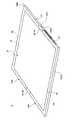
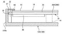
図1は、本発明の一実施形態に係る携帯用情報機器10を閉じて収納形態とした状態を示した斜視図である。図2は、図1に示す携帯用情報機器10を開いて使用形態とした状態を模式的に示した斜視図である。図3は、図2に示す携帯用情報機器10の側面断面図である。1. Description of Overall Configuration of Portable Information Device FIG. 1 is a perspective view showing a state in which the
図1及び図2に示すように、携帯用情報機器10は、第1筐体部材12A及び第2筐体部材12Bと、背表紙部14と、ディスプレイ16とを備える。本実施形態では携帯用情報機器10として本のように二つ折りに折り畳み可能なタブレット型PCを例示する。携帯用情報機器10は携帯電話、スマートフォン又は電子手帳等であってもよい。 As shown in FIGS. 1 and 2, the
各筐体部材12A,12Bは、それぞれ背表紙部14に対応する辺以外の3辺に側壁を起立形成した矩形の板状部材である。各筐体部材12A,12Bは、例えばステンレスやマグネシウム、アルミニウム等の金属板や炭素繊維等の強化繊維を含む繊維強化樹脂板で構成される。筐体部材12A,12Bの内面側には、支持プレート18を介してディスプレイ16が固定される(図3参照)。筐体部材12A,12B間は背表紙部14の両端部に設けられた一対のヒンジ機構19,19を介して連結される。ヒンジ機構19は、筐体部材12A,12B間を図1に示す収納形態と図3に示す使用形態とに折り畳み可能に連結している。 Each of the
各筐体部材12A,12Bは、背表紙部14側の内端面12Aa,12Baがヒンジ側となり、背表紙部14側とは反対側の外端面12Ab,12Bbが開放端部側となる。 In each
図3に示すように、第1筐体部材12Aの内面には、メイン基板20が導電ねじ22を用いて固定される。メイン基板20は、当該携帯用情報機器10の全体的な制御を行うための電子基板であり、中央演算装置(CPU)20aや図示しないメモリ等の各種電子部品が実装されている。導電ねじ22は、導電性を有する金属や樹脂等で形成されたねじである。 As shown in FIG. 3, the
第2筐体部材12Bの内面には、サブ基板24が導電ねじ22を用いて固定される。サブ基板24は、ディスプレイ16の表示を制御するコントローラとして機能する電子基板である。第2筐体部材12Bの内面には、サブ基板24と並んでバッテリ装置26が固定される。バッテリ装置26は、当該携帯用情報機器10の電源であり、図示しない電源ケーブルを介して外部電源から充電可能である。 The sub-substrate 24 is fixed to the inner surface of the
背表紙部14は、図1に示すように携帯用情報機器10を折り畳んだ際の背表紙となる可撓性を持った薄い板状部材である。本実施形態の場合、背表紙部14は内端面12Aa,12Baを覆うように筐体部材12A,12B間に亘って設けられている。背表紙部14は、筐体部材12A,12Bの内面で筐体部材12A,12Bの並び方向に沿ってスライド可能である。図3に示す使用形態において、背表紙部14は、互いの内端面12Aa,12Ba同士が突き当てられた筐体部材12A,12Bの内面上に沿って平板状に配置される。図1に示す収納形態において、背表紙部14は、互いに離間した筐体部材12A,12Bの内端面12Aa,12Ba間の隙間を覆い隠すように円弧状に配置される。 The
ディスプレイ16は、例えばタッチパネル式の液晶ディスプレイである。ディスプレイ16は、筐体部材12A,12Bを折り畳んだ際に一緒に折り畳み可能な構造である。ディスプレイ16は、例えば柔軟性の高いペーパー構造を持った有機EL等のフレキシブルディスプレイであり、筐体部材12A,12Bの開閉動作に伴って開閉する。ディスプレイ16は、支持プレート18を介して各筐体部材12A,12Bの内面側に取付固定される。ディスプレイ16は、その表示面(表面)の裏面16aが支持プレート18の表面18aに接着剤等を用いて貼着固定される。 The
図2及び図3に示すように、ディスプレイ16は、筐体部材12A,12Bの内面側に支持プレート18を介して取付固定された状態で、その表面の外周縁部にベゼル部材27が配設される。ベゼル部材27は、ディスプレイ16の表面の表示領域(アクティブ領域)R1を除く外周縁部の非表示領域(非アクティブ領域)R2を覆うように設けられる。 As shown in FIGS. 2 and 3, in a state where the
2.支持プレートの説明
支持プレート18について説明する。ディスプレイ16は極めて薄いため、単体で筐体部材12A,12Bに固定すると破損や不具合を生じる懸念がある。そこで、当該携帯用情報機器10では、ディスプレイ16の裏面16aに支持プレート18を固着したアセンブリ部品を筐体部材12A,12Bに取付固定している。2. Description of Support Plate The
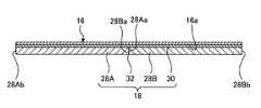
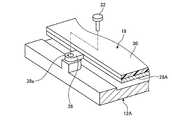
図4は、支持プレート18の構成を模式的に示した斜視図である。図5Aは、図4中のVA−VA線に沿う断面図である。図5Bは、図5Aに示す支持プレート18を二つ折りに折り畳んだ状態を示した側面断面図である。 FIG. 4 is a perspective view schematically showing the structure of the
図4〜図5Bに示すように、支持プレート18は、第1プレート部材28A及び第2プレート部材28Bと、シート状部材(可撓性シート状部材)30とを有する。 As shown in FIGS. 4 to 5B, the
第1プレート部材28Aは、第1筐体部材12Aの内面側に配置される矩形の板状部材である。第1プレート部材28Aの平面視での外形は第1筐体部材12Aよりも若干小さい(図3参照)。第2プレート部材28Bは、第2筐体部材12Bの内面側に配置される矩形の板状部材である。第2プレート部材28Bの平面視での外形は第2筐体部材12Bよりも若干小さい(図3参照)。各プレート部材28A,28Bは、例えばステンレスやマグネシウム、アルミニウム等の金属板や炭素繊維等の強化繊維を熱硬化性樹脂や熱可塑性樹脂からなるマトリクス樹脂に含浸させた繊維強化樹脂板で構成される。本実施形態では、炭素繊維を強化樹脂とした炭素繊維強化樹脂板を用いている。 The
第1プレート部材28A及び第2プレート部材28Bは、その表面18a,18a間に亘って固着されたシート状部材30により、二つ折りに折り畳み可能に連結されている。各プレート部材28A,28Bは、互いに対向する内端面(一端面)28Aa,28Baがヒンジ側となり、ヒンジ側とは反対側の外端面(他端面)28Ab,28Bbが開放端部側となる。 The
シート状部材30は、薄い樹脂膜や金属箔のような可撓性を持った材質で構成された薄膜である。シート状部材30は、各プレート部材28A,28Bの表面18aの全域に亘って固着されている。本実施形態では、シート状部材30としてステンレス製の金属箔を用いている。このシート状部材30は、接着剤等を用いてプレート部材28A,28Bの表面18aに接着される。シート状部材30の表面には、接着剤や両面テープ等を用いてディスプレイ16が固着される。シート状部材30は、各プレート部材28A,28Bの隣接端部である内端面28Aa,28Baを覆う部分が支持プレート18の折曲部(フレキシブルヒンジ)32として機能する。 The sheet-
この折曲部32では、筐体部材12A,12B間を平板状に開いた使用形態で、第1プレート部材28Aの内端面28Aaと第2プレート部材28Bの内端面28Baとが互いに当接する(図5A参照)。すなわち、内端面28Aa,28Ba間には隙間が形成されない。このため、支持プレート18は、硬質のプレート部材28A,28Bで使用形態にあるディスプレイ16の裏面16aの全域を支持することができる。その結果、ディスプレイ16の耐衝撃性が向上する。 In the bending
一方、筐体部材12A,12B間を折り畳んだ収納形態では、内端面28Aa,28Baが互いに離間して隙間34が形成される(図5B参照)。このため、シート状部材30は、折曲部32に対応する部分(図5B中で隙間34に露呈した部分)はプレート部材28A,28Bに対して接着されていない。 On the other hand, in the storage form in which the
図4に示すように、第1プレート部材28Aは、内端面28Aa以外の3辺の外周端面に1又は複数の取付片38がそれぞれ突出形成されている。取付片38は、第1プレート部材28Aの板厚と同一又は多少薄い板厚を持った先端円弧状の突出片である。取付片38には板厚方向に貫通した取付孔38aが形成されている。第2プレート部材28Bは、内端面28Ba以外の3辺の外周端部の裏面18bに1又は複数の取付部40がそれぞれ固定されている。取付部40は、矩形の薄板の下面に円柱状のピン40aを突設したボス部材である。ピン40aには、先端面に開口する雌ねじが軸方向に形成されている。各取付部40は、薄板の上面が接着剤や両面テープ等を用いて第2プレート部材28Bの裏面18bに固着される。なお、第2プレート部材28Bには、一部の外周端面に取付片38も設けられている。第1プレート部材28Aに取付部40を設けてもよい。 As shown in FIG. 4, in the
図6は、取付片38を用いた支持プレート18の筐体部材12A,12Bに対する固定構造を模式的に示した斜視図である。図7は、取付部40を用いた支持プレート18の筐体部材12A,12Bに対する固定構造を模式的に示した斜視図である。 FIG. 6 is a perspective view schematically showing a fixing structure of the
図3及び図6に示すように、各取付片38は、取付孔38aに挿通される導電ねじ22を介して第1プレート部材28Aに取付固定される。図3及び図7に示すように、各取付部40は、第2プレート部材28Bの外面に形成された座繰り孔部39に挿通される導電ねじ22を介して第2プレート部材28Bに取付固定される。 As shown in FIGS. 3 and 6, each
取付片38及び取付部40を用いることにより、支持プレート18(ディスプレイ16)は筐体部材12A,12Bの内面側でその外周縁部が保持されたトランポリンのような支持状態で取付固定される。これにより、支持プレート18が筐体部材12A,12Bの上部でクッション構造を持って支持される。本実施形態の場合、ディスプレイ16は薄いフレキシブルディスプレイであり、表面を硬質なガラス板等で保護できないために耐衝撃性が低いという問題もある。そこで、このクッション構造で支持プレート18を支持することで、ディスプレイ16上に物が落下したり当該携帯用情報機器10が落下したりすることによる衝撃や負荷を吸収できる。 By using the
図3に示すように、支持プレート18の裏面18bと、筐体部材12A,12Bの内面との間にクッション部材41を設けてもよい。クッション部材41を設けることで、上記のような外周縁部のみが支持された支持プレート18(ディスプレイ16)の中央部近傍を耐衝撃性を損なうことなく支持することができる。クッション部材41は、例えばシリコーン系のゲル材や発泡ゴム等で形成された柔軟な部材である。本実施形態では、クッション部材41としてシリコーン系のゲル材であるアルファゲル(登録商標)を用いている。 As shown in FIG. 3, a
3.ディスプレイに対する衝撃吸収構造の変形例の説明
上記の通り、ディスプレイ16は衝撃に弱いため、この衝撃を吸収するための構造を追加してもよい。図8は、制振部材として制振シート48を設けた構成例を示す要部拡大側面断面図である。図9は、制振部材として制振ばね49を設けた構成例を示す要部拡大側面断面図である。3. Description of Variations of Shock Absorbing Structure for Display As described above, since the
図8に示すように、制振シート48は、支持プレート18の裏面18bに接着剤や両面テープ等を用いて固着されている。制振シート48は、例えば外力を受けた場合にほとんど反発せず、衝撃や振動を吸収することができる材質で構成されたシートである。本実施形態では、制振シート48としてゴム系の制振材であるハネナイト(登録商標)やVBRAN(登録商標)を用いている。制振シート48を支持プレート18の裏面18bに設けることで、ディスプレイ16の表面に加えられた衝撃や振動が制振シート48によって吸収され、ディスプレイ16の耐衝撃性を向上できる。 As shown in FIG. 8, the damping
図9に示すように、制振ばね49は、例えば所定幅の板ばね部材をアーチ状に形成したばね部材である。制振ばね49は、筐体部材12A,12Bの内面に脚部が着地固定され、頂部が支持プレート18の裏面18bに当接又は近接配置される。制振ばね49を支持プレート18と筐体部材12A,12Bの間に介在させることで、ディスプレイ16の表面に加えられた衝撃や振動を吸収し、ディスプレイ16の耐衝撃性を向上できる。制振ばね49は、アーチ状ではなく、ダンパーやコイルばね等で構成されてもよい。 As shown in FIG. 9, the
4.配線構造及び配線方法の説明
当該携帯用情報機器10の配線構造及び配線方法について説明する。当該携帯用情報機器10は、二つ折りに折り畳み可能な構成を採用している。このため、電子基板や電子部品が左右の筐体部材12A,12Bの内面に適宜配置され、それらの間を接続する配線類を折り曲げされる背表紙部14に亘って設ける必要がある。しかも、これらの電子基板や配線類はディスプレイ16の裏面側に隠されるため、ディスプレイ16の取付構造を含め、その配線構造や配線方法を適切に構築することが望ましい。4. Description of Wiring Structure and Wiring Method The wiring structure and wiring method of the
4.1 配線構造の説明
先ず、配線構造を説明する。図10は、当該携帯用情報機器10の主要な配線構造を模式的に示した構成図であり、使用形態とした筐体部材12A,12Bの内面側をディスプレイ16を省略した平面視で図示している。4.1 Description of Wiring Structure First, the wiring structure will be described. FIG. 10 is a configuration diagram schematically showing the main wiring structure of the
図10に示すように、第1筐体部材12Aの内面には、メイン基板20、通信モジュール50及び冷却ファン52等が取付固定される。通信モジュール50は、アンテナ54で送受信する無線LAN(Local Area Network)等の各種無線通信の情報処理を行うデバイスである。冷却ファン52は、メイン基板20に実装された中央演算装置20a等での発熱を冷却するためのファンである。第2筐体部材12Bの内面には、サブ基板24、バッテリ装置26及びアンテナ54等が取付固定される。 As shown in FIG. 10, the
メイン基板20とサブ基板24との間は、背表紙部14を亘るメイン配線56によって電気的に接続される。メイン基板20とバッテリ装置26との間は、背表紙部14を亘るバッテリ配線58によって電気的に接続される。メイン配線56及びバッテリ配線58は、例えば複数本の配線束やフレキシブル基板等によって構成される。通信モジュール50とアンテナ54との間は、背表紙部14を亘る配線60によって電気的に接続される。当該携帯用情報機器10では、これらの他にも背表紙部14を亘る図示しない配線を複数有する。 The
なお、サブ基板24は、ディスプレイ16に対してサブ配線62によって電気的に接続される。サブ配線62は、例えば複数本の配線束やフレキシブル基板等によって構成される。サブ配線62は、第2筐体部材12Bに配置されるサブ基板24と、第2筐体部材12B側に配置されるディスプレイ16の長手方向で一端部16bとを接続する(図11Bも参照)。つまりサブ配線62は背表紙部14を跨がない。 The
4.2 配線方法の説明
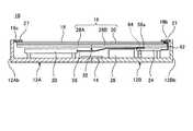
次に、配線方法を説明する。この配線方法は、ディスプレイ16で隠されるメイン配線56等を先に接続し、サブ配線62で折り返すことでディスプレイ16を設置する方法である。図11Aは、ディスプレイ16を裏返して外部に配置してメイン配線56を接続した状態を模式的に示した側面断面図である。図11Bは、図11Aに示す状態からディスプレイ16を筐体部材12A,12Bの内面側に取付固定した状態を模式的に示した側面断面図である。なお、図11A及び図11Bでは、取付片38や取付部40等を省略して図示している。4.2 Description of Wiring Method Next, the wiring method will be described. This wiring method is a method of installing the
図10及び図11Aに示すように、先ず、メイン配線56、バッテリ配線58及び配線60等の背表紙部14を跨ぐ配線を接続する。例えばメイン配線56は、サブ基板24に対してコネクタ56aを介して接続され、コネクタ56aはねじ64を用いてサブ基板24に強固に固定される。さらに、サブ配線62をサブ基板24とディスプレイ16の一端部16bとの間に接続し、ディスプレイ16をサブ配線62を介して裏返した状態で第2筐体部材12Bの外部に配置しておく。サブ配線62はメイン配線56等よりも先に接続してもよい。このため、ディスプレイ16が邪魔になることなくメイン配線56等を配策し接続できる。 As shown in FIG. 10 and FIG. 11A, first, wires across the
この際、これら背表紙部14を跨ぐメイン配線56等は、筐体部材12A,12Bの折り畳み動作に対応可能な余裕を持った位置に確実に配置し或いは固定しておく。これにより、筐体部材12A,12Bの開閉動作時にメイン配線56等の背表紙部14を跨ぐ配線に意図しない負荷や折曲げが生じることを回避できる。この際、筐体部材12A,12Bの内面がディスプレイ16で覆われていないため、背表紙部14を跨ぐメイン配線56等を所望の設計位置に容易に且つ確実に配策できる。 At this time, the
続いて、図11Bに示すようにサブ配線62を折り返してディスプレイ16を筐体部材12A,12Bの内面側に配置する。これによりディスプレイ16は、一端部16bが第2筐体部材12Bの外端面12Bb側に配置され、長手方向で反対側の他端部16cが第1筐体部材12Aの外端面12Ab側に配置される。そこで、図3に示すように取付片38及び取付部40を介して支持プレート18を筐体部材12A,12Bの内面側に固定し、ベゼル部材27を取り付ける。これにより、当該携帯用情報機器10の配線とディスプレイ16の取付固定が完了する。なお、サブ配線62は背表紙部14を跨がないため、ディスプレイ16を筐体部材12A,12Bの内面側に配置する際に多少は位置ずれを生じても問題はない。 Subsequently, as shown in FIG. 11B, the sub-wiring 62 is folded back to arrange the
5.グランド構造の説明
当該携帯用情報機器10のグランド構造について説明する。当該携帯用情報機器10は、二つ折りに折り畳み可能な構成を採用している。このため、各電子部品は左右の筐体部材12A,12Bに適宜配置され、ディスプレイ16は左右の筐体部材12A,12B間に亘って設けられる。特に、ディスプレイ16に有機ELのような自己発光素子を用いた場合、ディスプレイ16の一端側にあるアノード側から他端側にあるカソード側に向かって比較的大きな電流勾配を生じる。従って、この折り畳み構造の筐体部材12A,12B間で適切なフレームグランドを構築することが望まれる。5. Description of Ground Structure The ground structure of the
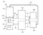
図12Aは、当該携帯用情報機器10の主要なグランド構造を模式的に示した側面図である。図12Bは、当該携帯用情報機器10の主要なグランド構造を模式的に示した構成図である。なお、図12A及び図12Bでは、支持プレート18のシート状部材30等の各要素を省略している。 FIG. 12A is a side view schematically showing the main ground structure of the
本実施形態の場合、各筐体部材12A,12B及び各プレート部材28A,28Bは導体で形成されている。図12A及び図12Bに示すように、メイン基板20及び第1プレート部材28Aは、それぞれ導電ねじ22を用いて第1筐体部材12Aに取付固定される(図3も参照)。サブ基板24及び第2プレート部材28Bは、それぞれ導電ねじ22を用いて第2筐体部材12Bに取付固定される(図3も参照)。その結果、メイン基板20及び第1プレート部材28Aと第1筐体部材12Aとの間が、それぞれ電気的に接続される。また、サブ基板24及び第2プレート部材28Bと第2筐体部材12Bとの間が、それぞれ電気的に接続される。 In the case of the present embodiment, the
そこで、第1プレート部材28Aの第1筐体部材12Aに対する導電ねじ22の締結部と、第2プレート部材28Bの第2筐体部材12Bに対する導電ねじ22の締結部との間に、背表紙部14を亘るグランド配線(第1導電部材)66を導電ねじ22による共締めで接続する(図4も参照)。これにより、第1プレート部材28Aと第2プレート部材28Bとの間が電気的に接続される。その結果、第1筐体部材12Aと第2筐体部材12Bとの間も電気的に接続される。 Therefore, the spine portion is between the fastening portion of the
次に、図12A及び図12Bに示すように、第1筐体部材12A側のメイン基板20と第2筐体部材12B側のサブ基板24とは、背表紙部14を亘るメイン配線56及びリターンパス67で電気的に接続される。なお、第2筐体部材12B側では、サブ基板24とディスプレイ16の一端部16bとがサブ配線62で電気的に接続される。その結果、ディスプレイ16の一端部16bと筐体部材12A,12Bとの間が電気的に接続される。このため、ディスプレイ16では、その長手方向で一端部16b側がアノード側となり、他端部16c側がカソード側となり、その間での電気抵抗値が増加して一端部16bから他端部16cに向かう電流勾配を生じる。 Next, as shown in FIGS. 12A and 12B, the
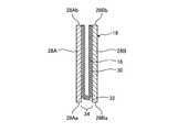
そこで、当該携帯用情報機器10では、第2筐体部材12B側においてディスプレイ16の他端部16cと第1プレート部材28Aとの間をグランドテープ(第2導電部材)68で接続する。グランドテープ68は、導電性を持った接着テープである。図13に示すように、グランドテープ68は、ディスプレイ16の他端部16cに露出させた導電パッド部16dと、第1プレート部材28Aとの間を繋ぐように支持プレート18の端面を介して貼着固定される。グランドテープ68に代えて、一般的なグランド配線を用いてもよい。これにより、ディスプレイ16の他端部16cと第1プレート部材28Aとの間が電気的に接続される。このため、ディスプレイ16の他端部16cと筐体部材12A,12Bの間も電気的に接続される。その結果、ディスプレイ16の電流駆動方向となる長手方向で一端部16bと他端部16cとの間でのグランドレベルが一定化される。以上より、当該携帯用情報機器10でのグランド構造が構築され、ノイズ(EMC)対策も図られる。 Therefore, in the
6.携帯用情報機器の作用効果の説明
以上のように、本実施形態に係る携帯用情報機器10では、第1筐体部材12Aと第2筐体部材12Bの内面側に固定されてディスプレイ16の裏面16aを支持する支持プレート18を備える。そして、支持プレート18は、第1筐体部材12Aの内面側に配置される第1プレート部材28Aと、第2筐体部材12Bの内面側に配置される第2プレート部材28Bと、第1プレート部材28Aと第2プレート部材28Bの間を二つ折りに折り畳み可能に連結するシート状部材30とを有する。6. As described above, in the
このように当該携帯用情報機器10は、折り畳み可能なフレキシブルディスプレイであるディスプレイ16の裏面16aを折り畳み可能な支持プレート18で支持している。従って、筐体部材12A,12Bの内面側でディスプレイ16を支持プレート18によって安定して支持することができる。その結果、ディスプレイ16に対する衝撃や負荷を支持プレート18で受け止めることができ、ディスプレイ16の不具合の発生を抑制できる。 Thus, the
シート状部材30は、第1プレート部材28A及び第2プレート部材28Bの表面18aの全域に亘って設けられると共に、その表面にディスプレイ16が固定される。従って、互いに連結された2枚のプレート部材28A,28Bを有する支持プレート18の表面全域に設けたシート状部材30で均一な平面とすることができる。これにより、ディスプレイ16を一層安定して支持することができ、不具合の発生を一層確実に抑制できる。 The sheet-
第1プレート部材28Aの一端面である内端面28Aaと、該内端面28Aaに対向する第2プレート部材28Bの一端面である内端面28Baとの間には、第1筐体部材12Aと第2筐体部材12Bとの間が二つ折りに折り畳まれた状態で隙間が形成される(図5B参照)一方、第1筐体部材12Aと第2筐体部材12Bとの間が平板状に開かれた状態では隙間が形成されない(図5A参照)。これにより、携帯用情報機器10が使用形態にある場合、ディスプレイ16の折曲部32に対応する部分にも柔軟なシート状部材30だけでなく硬質のプレート部材28A,28Bが配設される。その結果、ディスプレイ16の耐衝撃性が折曲部32に対応する部分で脆弱になることを防止でき、その全域に亘って高い耐衝撃性を確保できる。 A
携帯用情報機器10では、第1プレート部材28A及び第2プレート部材28Bに繊維強化樹脂板、特に炭素繊維強化樹脂板を用い、シート状部材30に金属箔、特にステンレスシートを用いている。この組み合わせの支持プレート18は、耐衝撃吸収性、屈曲耐久性、表面の平面度等の点でより高い効果が得られる。なお、シート状部材30を形成するステンレスシートの厚みはステンレス材料の種類や折曲の曲率等にもよるが、例えば40μm程度が好ましい。 In the
プレート部材28A,28Bは、その外周端面の一部から外方に突出した取付片38を有し、取付片38を介して筐体部材12A,12Bに固定される。これにより、ディスプレイ16を支持する支持プレート18が筐体部材12A,12Bの内面側でトランポリンのようなクッション構造で取付固定される。その結果、ディスプレイ16の耐衝撃性が向上する。取付片38はプレート部材28A,28Aのいずれか一方のみに設けられてもよい。 The
このような取付片38は、プレート部材28A,28Bの外周端面から外方に突出している。このため、硬質な支持点となる取付片38の筐体部材12A,12Bに対する締結部をディスプレイ16の表示領域R1から可及的に離間させることができ、表示領域R1に対する衝撃を効果的に緩和できる。 Such a mounting
ところが、図3に示すように、ディスプレイ16の表示領域R1は、必ずしもディスプレイ16の外形の中心に配置されているわけではない。すなわち、ディスプレイ16は、例えばその長手方向の一端側(一端部16b)にサブ配線62が接続されるため(図12A参照)、表示領域R1を形成する各素子からサブ配線62までの配線がこの一端部16b側に集合する。そこで、本実施形態の場合はディスプレイ16の一端部16b側の非表示領域R2を他端部16c側の非表示領域R2よりも幅広に構成している(図3参照)。一方、ディスプレイ16の表示領域R1は、使用形態とした筐体部材12A,12Bに対してはその外形の中心に配置されることが望ましい。そこで、本実施形態の場合は、ディスプレイ16の一端部16bと第2筐体部材12Bの外壁(外端面12Bb)との間の隙間を、他端部16cと第1筐体部材12Aの外壁(外端面12Ab)との間の隙間よりも狭く設定し、表示領域R1を筐体部材12A,12Bの中心に設定している。 However, as shown in FIG. 3, the display area R1 of the
このような理由により、ディスプレイ16の裏面16aの全域を支持する支持プレート18は、ディスプレイ16の一端部16bを支持する端面から取付片38を突出させることが難しい構造となっている。そこで、当該携帯用情報機器10では、このディスプレイ16の一端部16bに対応する第2プレート部材28Bの外周縁部には外方に突出しない構成の取付部40を用いている。その結果、当該携帯用情報機器10は、筐体構造の大型化の抑制と支持プレート18によるディスプレイ16の確実な支持とを両立している。 For this reason, the
なお、本発明は、上記した実施形態に限定されるものではなく、本発明の主旨を逸脱しない範囲で自由に変更できることは勿論である。 In addition, this invention is not limited to above-described embodiment, Of course, it can change freely in the range which does not deviate from the main point of this invention.
10 携帯用情報機器
12A 第1筐体部材
12B 第2筐体部材
14 背表紙部
16 ディスプレイ
18 支持プレート
19 ヒンジ機構
20 メイン基板
20a 中央演算装置
22 導電ねじ
24 サブ基板
26 バッテリ装置
28A 第1プレート部材
28B 第2プレート部材
30 シート状部材
32 折曲部
34 隙間
38 取付片
40 取付部
41 クッション部材
48 制振シート
49 制振ばね
56 メイン配線
58 バッテリ配線
60 配線
62 サブ配線
66 グランド配線
68 グランドテープ
DESCRIPTION OF
Claims (8)
Translated fromJapanese前記第1筐体部材と前記第2筐体部材の内面側に固定されて前記ディスプレイの裏面を支持する支持プレートを備え、
前記支持プレートは、前記第1筐体部材の内面側に配置される第1プレート部材と、前記第2筐体部材の内面側に配置される第2プレート部材と、前記第1プレート部材と前記第2プレート部材の間を二つ折りに折り畳み可能に連結する可撓性シート状部材とを有し、
前記第1筐体部材と前記第2筐体部材との間が電気的に接続され、
前記ディスプレイの一端部と前記第2筐体部材との間が電気的に接続され、
前記ディスプレイの一端部とは反対側の他端部と前記第1筐体部材との間が電気的に接続されていることを特徴とする携帯用情報機器。A first housing member and a second housing member which can be folded in half, and a display which is provided between the first housing member and the inner surface of the second housing member and which can be folded in half A portable information device provided,
A support plate fixed to the inner surface side of the first housing member and the second housing member to support the back surface of the display;
The support plate includes a first plate member disposed on the inner surface side of the first casing member, a second plate member disposed on the inner surface side of the second casing member, the first plate member, and the first plate member. And a flexible sheet-like member foldably connected in half between the second plate members,
The first housing member and the second housing member are electrically connected,
Electrically connected between an end of the display and the second housing member;
A portable information device, wherein the other end opposite to the one end of the display and the first housing member are electrically connected.
前記第1筐体部材は前記第1プレート部材と電気的に接続される一方、前記第2筐体部材は前記第2プレート部材と電気的に接続されており、
前記第1プレート部材と前記第2プレート部材との間を電気的に接続することで、前記第1筐体部材と前記第2筐体部材との間を電気的に接続する第1導電部材と、
前記ディスプレイの他端部と前記第1プレート部材との間を電気的に接続することで、前記ディスプレイの他端部と前記第1筐体部材との間を電気的に接続する第2導電部材と、
を備えることを特徴とする携帯用情報機器。In the portable information device according to claim1 ,
The first housing member is electrically connected to the first plate member, and the second housing member is electrically connected to the second plate member.
A first conductive member electrically connecting the first housing member and the second housing member by electrically connecting the first plate member and the second plate member ,
A second conductive member electrically connecting between the other end of the display and the first housing member by electrically connecting the other end of the display and the first plate member When,
A portable information device comprising:
前記第1プレート部材及び前記第2プレート部材は、繊維強化樹脂板で形成され、
前記可撓性シート状部材は、金属箔で形成されていることを特徴とする携帯用情報機器。The portable information device according to claim 1or 2
The first plate member and the second plate member are formed of a fiber reinforced resin plate,
The portable information device characterized in that the flexible sheet-like member is formed of metal foil.
前記第1プレート部材及び前記第2プレート部材の少なくとも一方は、その外周端面の一部から外方に突出した取付片を有し、該取付片を介して前記第1筐体部材又は前記第2筐体部材に固定されていることを特徴とする携帯用情報機器。The portable information device according to any one of claims 1 to3 .
At least one of the first plate member and the second plate member has a mounting piece projecting outward from a part of the outer peripheral end face, and the first housing member or the second plate member is formed via the mounting piece. A portable information device characterized in that it is fixed to a housing member.
前記第1プレート部材及び前記第2プレート部材の少なくとも一方は、その外周縁部の裏面から突出する取付部を有し、該取付部を介して前記第1筐体部材又は前記第2筐体部材に固定されていることを特徴とする携帯用情報機器。The portable information device according to any one of claims 1 to4 .
At least one of the first plate member and the second plate member has a mounting portion that protrudes from the back surface of the outer peripheral edge portion, and the first housing member or the second housing member via the mounting portion A portable information device characterized in that it is fixed to.
前記支持プレートの裏面と、前記第1筐体部材及び前記第2筐体部材の少なくとも一方の内面との間にクッション部材を介在させたことを特徴とする携帯用情報機器。The portable information device according to any one of claims 1 to5 .
A cushioning member is interposed between the back surface of the support plate and the inner surface of at least one of the first housing member and the second housing member.
前記支持プレートの裏面側に制振部材を設けたことを特徴とする携帯用情報機器。The portable information device according to any one of claims 1 to6 .
A portable information device characterized in that a damping member is provided on the back surface side of the support plate.
前記第1筐体部材の内面には演算装置が実装されるメイン基板が設けられる一方、前記第2筐体部材の内面には前記ディスプレイの表示を制御するサブ基板が設けられており、
前記メイン基板と前記サブ基板との間は、前記第1筐体部材と前記第2筐体部材との間に亘るメイン配線によって電気的に接続され、
前記ディスプレイは、前記第2筐体部材の内面側に位置する部分から引き出されたサブ配線によって前記サブ基板と電気的に接続されていることを特徴とする携帯用情報機器。The portable information device according to any one of claims 1 to7 .
A main substrate on which an arithmetic unit is mounted is provided on the inner surface of the first housing member, and a sub-substrate for controlling display of the display is provided on the inner surface of the second housing member,
The main substrate and the sub substrate are electrically connected by a main wiring extending between the first housing member and the second housing member,
A portable information device characterized in that the display is electrically connected to the sub substrate by a sub wiring drawn from a portion located on the inner surface side of the second housing member.
Priority Applications (4)
| Application Number | Priority Date | Filing Date | Title |
|---|---|---|---|
| JP2017002062AJP6535353B2 (en) | 2017-01-10 | 2017-01-10 | Portable information equipment |
| US15/855,634US10228722B2 (en) | 2017-01-10 | 2017-12-27 | Portable information device |
| CN201810029390.3ACN108319332A (en) | 2017-01-10 | 2018-01-09 | Portable information device |
| US16/242,735US10409332B2 (en) | 2017-01-10 | 2019-01-08 | Portable information device |
Applications Claiming Priority (1)
| Application Number | Priority Date | Filing Date | Title |
|---|---|---|---|
| JP2017002062AJP6535353B2 (en) | 2017-01-10 | 2017-01-10 | Portable information equipment |
Related Child Applications (1)
| Application Number | Title | Priority Date | Filing Date |
|---|---|---|---|
| JP2018033034ADivisionJP6491770B2 (en) | 2018-02-27 | 2018-02-27 | Portable information equipment |
Publications (2)
| Publication Number | Publication Date |
|---|---|
| JP2018112833A JP2018112833A (en) | 2018-07-19 |
| JP6535353B2true JP6535353B2 (en) | 2019-06-26 |
Family
ID=62783085
Family Applications (1)
| Application Number | Title | Priority Date | Filing Date |
|---|---|---|---|
| JP2017002062AActiveJP6535353B2 (en) | 2017-01-10 | 2017-01-10 | Portable information equipment |
Country Status (3)
| Country | Link |
|---|---|
| US (1) | US10228722B2 (en) |
| JP (1) | JP6535353B2 (en) |
| CN (1) | CN108319332A (en) |
Families Citing this family (30)
| Publication number | Priority date | Publication date | Assignee | Title |
|---|---|---|---|---|
| US10754377B2 (en)* | 2017-04-05 | 2020-08-25 | Microsoft Technology Licensing, Llc | Hinged device |
| CN208190691U (en)* | 2018-01-08 | 2018-12-04 | 杭州安费诺飞凤通信部品有限公司 | Semi-automatic infolding flexible screen mobile terminal hinge and infolding flexible screen mobile terminal |
| CN108712538B (en)* | 2018-07-27 | 2021-06-04 | 北京小米移动软件有限公司 | Foldable device and installation method |
| JP2020046541A (en)* | 2018-09-19 | 2020-03-26 | レノボ・シンガポール・プライベート・リミテッド | Portable information appliance |
| KR102524510B1 (en)* | 2018-11-21 | 2023-04-20 | 엘지디스플레이 주식회사 | Foldable display device |
| KR102731955B1 (en)* | 2019-02-19 | 2024-11-20 | 삼성전자주식회사 | Foldable electronic device including protection member |
| KR102638661B1 (en)* | 2019-02-19 | 2024-02-21 | 삼성전자주식회사 | Electronic device having battery |
| KR102676303B1 (en) | 2019-02-19 | 2024-06-18 | 삼성전자 주식회사 | Electronic device for preventing unintended user input and method for the same |
| KR102724533B1 (en)* | 2019-02-25 | 2024-11-04 | 삼성디스플레이 주식회사 | Display device |
| US10761572B1 (en) | 2019-03-25 | 2020-09-01 | Microsoft Technology Licensing, Llc | Hinged device |
| WO2020230745A1 (en)* | 2019-05-16 | 2020-11-19 | ソニー株式会社 | Heat transfer mechanism |
| JP2020201698A (en) | 2019-06-10 | 2020-12-17 | レノボ・シンガポール・プライベート・リミテッド | Portable information device and display assembly |
| WO2020262739A1 (en)* | 2019-06-28 | 2020-12-30 | 엘지전자 주식회사 | Avn device |
| JP6828105B1 (en) | 2019-08-27 | 2021-02-10 | レノボ・シンガポール・プライベート・リミテッド | Portable information equipment |
| JP6837106B2 (en) | 2019-08-27 | 2021-03-03 | レノボ・シンガポール・プライベート・リミテッド | Portable information equipment |
| JP2021033776A (en) | 2019-08-27 | 2021-03-01 | レノボ・シンガポール・プライベート・リミテッド | Portable information device |
| JP2021043492A (en)* | 2019-09-06 | 2021-03-18 | レノボ・シンガポール・プライベート・リミテッド | Electronic device |
| KR102751451B1 (en)* | 2019-10-22 | 2025-01-10 | 삼성전자주식회사 | Foldable electronic device including display protection structure |
| JP6884189B2 (en)* | 2019-10-29 | 2021-06-09 | レノボ・シンガポール・プライベート・リミテッド | Portable information devices and their manufacturing methods |
| CN114945966A (en) | 2020-01-10 | 2022-08-26 | 株式会社半导体能源研究所 | Angle adjusting device, supporting tool and display device |
| JP6898485B1 (en) | 2020-02-21 | 2021-07-07 | レノボ・シンガポール・プライベート・リミテッド | Portable information equipment and display assembly |
| JP6971354B2 (en)* | 2020-05-13 | 2021-11-24 | レノボ・シンガポール・プライベート・リミテッド | How to make display assemblies, portable information devices, display assemblies, and how to make portable information devices. |
| WO2021235725A1 (en)* | 2020-05-19 | 2021-11-25 | 엘지이노텍 주식회사 | Elastic member |
| JP7022176B2 (en) | 2020-07-10 | 2022-02-17 | レノボ・シンガポール・プライベート・リミテッド | Portable information equipment and microphone pressing parts |
| JP2022067198A (en)* | 2020-10-20 | 2022-05-06 | レノボ・シンガポール・プライベート・リミテッド | Portable information device and display assembly |
| JP2022076259A (en) | 2020-11-09 | 2022-05-19 | レノボ・シンガポール・プライベート・リミテッド | Method for manufacturing display device |
| JP2022078601A (en)* | 2020-11-13 | 2022-05-25 | レノボ・シンガポール・プライベート・リミテッド | Information equipment |
| JP7143457B2 (en) | 2021-01-19 | 2022-09-28 | レノボ・シンガポール・プライベート・リミテッド | Electronics |
| JP7170086B2 (en) | 2021-04-22 | 2022-11-11 | レノボ・シンガポール・プライベート・リミテッド | Electronics |
| KR20220167844A (en) | 2021-06-14 | 2022-12-22 | 삼성디스플레이 주식회사 | Display device and electronic device including the same |
Family Cites Families (20)
| Publication number | Priority date | Publication date | Assignee | Title |
|---|---|---|---|---|
| JP2005114759A (en)* | 2003-10-02 | 2005-04-28 | Canon Inc | Display device, mobile phone, and electronic device |
| US20080094787A1 (en)* | 2004-03-15 | 2008-04-24 | Olympus Technologies Pte Ltd. | Portable Electronic Device |
| KR101221428B1 (en)* | 2004-07-20 | 2013-01-11 | 김시환 | Portable Display Device |
| JP2007335622A (en)* | 2006-06-15 | 2007-12-27 | Fujitsu Ltd | Electronic equipment |
| KR20100092222A (en)* | 2009-02-12 | 2010-08-20 | 삼성전자주식회사 | Multi-foldable mobile display apparatus |
| JP5307631B2 (en)* | 2009-05-27 | 2013-10-02 | 京セラ株式会社 | Portable electronic devices |
| EP3826278B1 (en)* | 2011-07-11 | 2024-06-12 | Samsung Electronics Co., Ltd. | Flexible display with guided plates to support the display in the open position |
| JP5319825B1 (en)* | 2012-05-22 | 2013-10-16 | 株式会社東芝 | Electronics |
| US9524030B2 (en) | 2013-04-26 | 2016-12-20 | Immersion Corporation | Haptic feedback for interactions with foldable-bendable displays |
| KR102190539B1 (en)* | 2013-08-30 | 2020-12-15 | 가부시키가이샤 한도오따이 에네루기 켄큐쇼 | Display device |
| US9798359B2 (en)* | 2014-02-21 | 2017-10-24 | Samsung Electronics Co., Ltd. | Foldable device |
| KR20250083577A (en)* | 2014-02-28 | 2025-06-10 | 가부시키가이샤 한도오따이 에네루기 켄큐쇼 | Electronic device |
| KR102261641B1 (en)* | 2014-05-13 | 2021-06-08 | 삼성디스플레이 주식회사 | Foldable display apparatus |
| KR102202228B1 (en)* | 2014-06-11 | 2021-01-13 | 삼성전자 주식회사 | Electronic device comprising a flexible display |
| KR20160024605A (en)* | 2014-08-26 | 2016-03-07 | 삼성전자주식회사 | Foldable device |
| KR102226694B1 (en)* | 2014-09-01 | 2021-03-11 | 엘지디스플레이 주식회사 | Foldable display apparatus |
| KR102233119B1 (en)* | 2014-09-23 | 2021-03-30 | 삼성디스플레이 주식회사 | Display device |
| CN107148602B (en)* | 2014-11-18 | 2020-02-04 | 夏普株式会社 | Display device |
| WO2017003415A1 (en)* | 2015-06-27 | 2017-01-05 | Intel Corporation | Flexible display structure |
| CN205793587U (en)* | 2016-05-31 | 2016-12-07 | 深圳拓邦股份有限公司 | A kind of display module of antistatic |
- 2017
- 2017-01-10JPJP2017002062Apatent/JP6535353B2/enactiveActive
- 2017-12-27USUS15/855,634patent/US10228722B2/enactiveActive
- 2018
- 2018-01-09CNCN201810029390.3Apatent/CN108319332A/enactivePending
Also Published As
| Publication number | Publication date |
|---|---|
| US10228722B2 (en) | 2019-03-12 |
| US20180196467A1 (en) | 2018-07-12 |
| CN108319332A (en) | 2018-07-24 |
| JP2018112833A (en) | 2018-07-19 |
Similar Documents
| Publication | Publication Date | Title |
|---|---|---|
| JP6535353B2 (en) | Portable information equipment | |
| US10409332B2 (en) | Portable information device | |
| JP6507183B2 (en) | Portable information equipment | |
| KR102056721B1 (en) | Foldable computing apparatus and Method for erecting display unit | |
| JP6429909B2 (en) | Portable information equipment | |
| JP6491770B2 (en) | Portable information equipment | |
| US11449103B2 (en) | Flexible display device having support layer | |
| JP5286875B2 (en) | Display device and electronic apparatus equipped with display device | |
| KR20210047753A (en) | Foldable electronic device including display protection structure | |
| JP6513732B2 (en) | Portable information equipment | |
| JP5574420B2 (en) | Portable electronic devices | |
| JP2012034064A (en) | Portable electronic apparatus | |
| JP4393567B1 (en) | Electronics | |
| JP2012084800A (en) | Multilayer flexible substrate and electronic apparatus | |
| WO2012115164A1 (en) | Mobile electronic device | |
| US12399540B2 (en) | Electronic apparatus | |
| US12287682B2 (en) | Electronic apparatus | |
| JP6532972B2 (en) | Portable information equipment | |
| JP2008083982A (en) | Electronics | |
| JP4282671B2 (en) | Electronics | |
| JP2007034939A (en) | Electronics | |
| US20080030942A1 (en) | Folding Electronic Device | |
| JP6421263B2 (en) | Portable information equipment | |
| JP7345134B2 (en) | Electronics | |
| JP6631083B2 (en) | Information processing equipment |
Legal Events
| Date | Code | Title | Description |
|---|---|---|---|
| A977 | Report on retrieval | Free format text:JAPANESE INTERMEDIATE CODE: A971007 Effective date:20181011 | |
| A131 | Notification of reasons for refusal | Free format text:JAPANESE INTERMEDIATE CODE: A131 Effective date:20181016 | |
| A521 | Request for written amendment filed | Free format text:JAPANESE INTERMEDIATE CODE: A523 Effective date:20181226 | |
| A131 | Notification of reasons for refusal | Free format text:JAPANESE INTERMEDIATE CODE: A131 Effective date:20190219 | |
| A521 | Request for written amendment filed | Free format text:JAPANESE INTERMEDIATE CODE: A523 Effective date:20190424 | |
| TRDD | Decision of grant or rejection written | ||
| A01 | Written decision to grant a patent or to grant a registration (utility model) | Free format text:JAPANESE INTERMEDIATE CODE: A01 Effective date:20190521 | |
| A61 | First payment of annual fees (during grant procedure) | Free format text:JAPANESE INTERMEDIATE CODE: A61 Effective date:20190531 | |
| R150 | Certificate of patent or registration of utility model | Ref document number:6535353 Country of ref document:JP Free format text:JAPANESE INTERMEDIATE CODE: R150 | |
| R250 | Receipt of annual fees | Free format text:JAPANESE INTERMEDIATE CODE: R250 | |
| R250 | Receipt of annual fees | Free format text:JAPANESE INTERMEDIATE CODE: R250 | |
| R250 | Receipt of annual fees | Free format text:JAPANESE INTERMEDIATE CODE: R250 | |
| R250 | Receipt of annual fees | Free format text:JAPANESE INTERMEDIATE CODE: R250 |