JP6535339B2 - Display device with improved contrast - Google Patents
Display device with improved contrastDownload PDFInfo
- Publication number
- JP6535339B2 JP6535339B2JP2016552586AJP2016552586AJP6535339B2JP 6535339 B2JP6535339 B2JP 6535339B2JP 2016552586 AJP2016552586 AJP 2016552586AJP 2016552586 AJP2016552586 AJP 2016552586AJP 6535339 B2JP6535339 B2JP 6535339B2
- Authority
- JP
- Japan
- Prior art keywords
- area
- illumination
- display
- light
- illuminated
- Prior art date
- Legal status (The legal status is an assumption and is not a legal conclusion. Google has not performed a legal analysis and makes no representation as to the accuracy of the status listed.)
- Active
Links
Images


Classifications
- G—PHYSICS
- G02—OPTICS
- G02B—OPTICAL ELEMENTS, SYSTEMS OR APPARATUS
- G02B26/00—Optical devices or arrangements for the control of light using movable or deformable optical elements
- G02B26/02—Optical devices or arrangements for the control of light using movable or deformable optical elements for controlling the intensity of light
- G—PHYSICS
- G02—OPTICS
- G02B—OPTICAL ELEMENTS, SYSTEMS OR APPARATUS
- G02B27/00—Optical systems or apparatus not provided for by any of the groups G02B1/00 - G02B26/00, G02B30/00
- G02B27/30—Collimators
- G—PHYSICS
- G02—OPTICS
- G02B—OPTICAL ELEMENTS, SYSTEMS OR APPARATUS
- G02B5/00—Optical elements other than lenses
- G02B5/08—Mirrors
- G02B5/10—Mirrors with curved faces
- G—PHYSICS
- G09—EDUCATION; CRYPTOGRAPHY; DISPLAY; ADVERTISING; SEALS
- G09G—ARRANGEMENTS OR CIRCUITS FOR CONTROL OF INDICATING DEVICES USING STATIC MEANS TO PRESENT VARIABLE INFORMATION
- G09G3/00—Control arrangements or circuits, of interest only in connection with visual indicators other than cathode-ray tubes
- G09G3/20—Control arrangements or circuits, of interest only in connection with visual indicators other than cathode-ray tubes for presentation of an assembly of a number of characters, e.g. a page, by composing the assembly by combination of individual elements arranged in a matrix no fixed position being assigned to or needed to be assigned to the individual characters or partial characters
- G09G3/22—Control arrangements or circuits, of interest only in connection with visual indicators other than cathode-ray tubes for presentation of an assembly of a number of characters, e.g. a page, by composing the assembly by combination of individual elements arranged in a matrix no fixed position being assigned to or needed to be assigned to the individual characters or partial characters using controlled light sources
- G09G3/30—Control arrangements or circuits, of interest only in connection with visual indicators other than cathode-ray tubes for presentation of an assembly of a number of characters, e.g. a page, by composing the assembly by combination of individual elements arranged in a matrix no fixed position being assigned to or needed to be assigned to the individual characters or partial characters using controlled light sources using electroluminescent panels
- G09G3/32—Control arrangements or circuits, of interest only in connection with visual indicators other than cathode-ray tubes for presentation of an assembly of a number of characters, e.g. a page, by composing the assembly by combination of individual elements arranged in a matrix no fixed position being assigned to or needed to be assigned to the individual characters or partial characters using controlled light sources using electroluminescent panels semiconductive, e.g. using light-emitting diodes [LED]
- G09G3/3208—Control arrangements or circuits, of interest only in connection with visual indicators other than cathode-ray tubes for presentation of an assembly of a number of characters, e.g. a page, by composing the assembly by combination of individual elements arranged in a matrix no fixed position being assigned to or needed to be assigned to the individual characters or partial characters using controlled light sources using electroluminescent panels semiconductive, e.g. using light-emitting diodes [LED] organic, e.g. using organic light-emitting diodes [OLED]
- G—PHYSICS
- G09—EDUCATION; CRYPTOGRAPHY; DISPLAY; ADVERTISING; SEALS
- G09G—ARRANGEMENTS OR CIRCUITS FOR CONTROL OF INDICATING DEVICES USING STATIC MEANS TO PRESENT VARIABLE INFORMATION
- G09G3/00—Control arrangements or circuits, of interest only in connection with visual indicators other than cathode-ray tubes
- G09G3/20—Control arrangements or circuits, of interest only in connection with visual indicators other than cathode-ray tubes for presentation of an assembly of a number of characters, e.g. a page, by composing the assembly by combination of individual elements arranged in a matrix no fixed position being assigned to or needed to be assigned to the individual characters or partial characters
- G09G3/34—Control arrangements or circuits, of interest only in connection with visual indicators other than cathode-ray tubes for presentation of an assembly of a number of characters, e.g. a page, by composing the assembly by combination of individual elements arranged in a matrix no fixed position being assigned to or needed to be assigned to the individual characters or partial characters by control of light from an independent source
- G09G3/36—Control arrangements or circuits, of interest only in connection with visual indicators other than cathode-ray tubes for presentation of an assembly of a number of characters, e.g. a page, by composing the assembly by combination of individual elements arranged in a matrix no fixed position being assigned to or needed to be assigned to the individual characters or partial characters by control of light from an independent source using liquid crystals
- G—PHYSICS
- G09—EDUCATION; CRYPTOGRAPHY; DISPLAY; ADVERTISING; SEALS
- G09G—ARRANGEMENTS OR CIRCUITS FOR CONTROL OF INDICATING DEVICES USING STATIC MEANS TO PRESENT VARIABLE INFORMATION
- G09G5/00—Control arrangements or circuits for visual indicators common to cathode-ray tube indicators and other visual indicators
- G09G5/10—Intensity circuits
- H—ELECTRICITY
- H01—ELECTRIC ELEMENTS
- H01J—ELECTRIC DISCHARGE TUBES OR DISCHARGE LAMPS
- H01J31/00—Cathode ray tubes; Electron beam tubes
- H01J31/08—Cathode ray tubes; Electron beam tubes having a screen on or from which an image or pattern is formed, picked up, converted, or stored
- H01J31/10—Image or pattern display tubes, i.e. having electrical input and optical output; Flying-spot tubes for scanning purposes
- H01J31/12—Image or pattern display tubes, i.e. having electrical input and optical output; Flying-spot tubes for scanning purposes with luminescent screen
- H—ELECTRICITY
- H10—SEMICONDUCTOR DEVICES; ELECTRIC SOLID-STATE DEVICES NOT OTHERWISE PROVIDED FOR
- H10K—ORGANIC ELECTRIC SOLID-STATE DEVICES
- H10K50/00—Organic light-emitting devices
- H—ELECTRICITY
- H10—SEMICONDUCTOR DEVICES; ELECTRIC SOLID-STATE DEVICES NOT OTHERWISE PROVIDED FOR
- H10K—ORGANIC ELECTRIC SOLID-STATE DEVICES
- H10K50/00—Organic light-emitting devices
- H10K50/80—Constructional details
- H10K50/85—Arrangements for extracting light from the devices
- H10K50/858—Arrangements for extracting light from the devices comprising refractive means, e.g. lenses
- H—ELECTRICITY
- H10—SEMICONDUCTOR DEVICES; ELECTRIC SOLID-STATE DEVICES NOT OTHERWISE PROVIDED FOR
- H10K—ORGANIC ELECTRIC SOLID-STATE DEVICES
- H10K50/00—Organic light-emitting devices
- H10K50/80—Constructional details
- H10K50/86—Arrangements for improving contrast, e.g. preventing reflection of ambient light
- H—ELECTRICITY
- H10—SEMICONDUCTOR DEVICES; ELECTRIC SOLID-STATE DEVICES NOT OTHERWISE PROVIDED FOR
- H10K—ORGANIC ELECTRIC SOLID-STATE DEVICES
- H10K59/00—Integrated devices, or assemblies of multiple devices, comprising at least one organic light-emitting element covered by group H10K50/00
- H10K59/10—OLED displays
- H10K59/19—Segment displays
- H—ELECTRICITY
- H10—SEMICONDUCTOR DEVICES; ELECTRIC SOLID-STATE DEVICES NOT OTHERWISE PROVIDED FOR
- H10K—ORGANIC ELECTRIC SOLID-STATE DEVICES
- H10K59/00—Integrated devices, or assemblies of multiple devices, comprising at least one organic light-emitting element covered by group H10K50/00
- H10K59/80—Constructional details
- H10K59/875—Arrangements for extracting light from the devices
- H10K59/879—Arrangements for extracting light from the devices comprising refractive means, e.g. lenses
- H—ELECTRICITY
- H10—SEMICONDUCTOR DEVICES; ELECTRIC SOLID-STATE DEVICES NOT OTHERWISE PROVIDED FOR
- H10K—ORGANIC ELECTRIC SOLID-STATE DEVICES
- H10K59/00—Integrated devices, or assemblies of multiple devices, comprising at least one organic light-emitting element covered by group H10K50/00
- H10K59/80—Constructional details
- H10K59/8791—Arrangements for improving contrast, e.g. preventing reflection of ambient light
- G—PHYSICS
- G09—EDUCATION; CRYPTOGRAPHY; DISPLAY; ADVERTISING; SEALS
- G09G—ARRANGEMENTS OR CIRCUITS FOR CONTROL OF INDICATING DEVICES USING STATIC MEANS TO PRESENT VARIABLE INFORMATION
- G09G2300/00—Aspects of the constitution of display devices
- G09G2300/04—Structural and physical details of display devices
- G—PHYSICS
- G09—EDUCATION; CRYPTOGRAPHY; DISPLAY; ADVERTISING; SEALS
- G09G—ARRANGEMENTS OR CIRCUITS FOR CONTROL OF INDICATING DEVICES USING STATIC MEANS TO PRESENT VARIABLE INFORMATION
- G09G2320/00—Control of display operating conditions
- G09G2320/06—Adjustment of display parameters
- G09G2320/066—Adjustment of display parameters for control of contrast
- G—PHYSICS
- G09—EDUCATION; CRYPTOGRAPHY; DISPLAY; ADVERTISING; SEALS
- G09G—ARRANGEMENTS OR CIRCUITS FOR CONTROL OF INDICATING DEVICES USING STATIC MEANS TO PRESENT VARIABLE INFORMATION
- G09G2360/00—Aspects of the architecture of display systems
- G09G2360/14—Detecting light within display terminals, e.g. using a single or a plurality of photosensors
- G09G2360/144—Detecting light within display terminals, e.g. using a single or a plurality of photosensors the light being ambient light
Landscapes
- Physics & Mathematics (AREA)
- General Physics & Mathematics (AREA)
- Optics & Photonics (AREA)
- Engineering & Computer Science (AREA)
- Computer Hardware Design (AREA)
- Theoretical Computer Science (AREA)
- Chemical & Material Sciences (AREA)
- Crystallography & Structural Chemistry (AREA)
- Devices For Indicating Variable Information By Combining Individual Elements (AREA)
- Electroluminescent Light Sources (AREA)
- Optical Elements Other Than Lenses (AREA)
- Optical Filters (AREA)
- Liquid Crystal (AREA)
Description
Translated fromJapanese本発明は複数の画素を有する表示領域を備えた表示装置に関するものである。従来技術においてこのような表示装置としては、たとえば液晶ディスプレイ(LCD)装置や有機発光ダイオード(OLED)表示装置などが知られている。このような表示装置の欠点は、これらの表示装置が有する限定されたコントラスト範囲である。The present invention relates to a display device provided with a display area having a plurality of pixels. As such a display device in the prior art, for example, a liquid crystal display (LCD) device and an organic light emitting diode (OLED) display device are known. The disadvantage of such displays is the limited contrast range that these displays have.
米国特許出願公開2008/0024470号明細書により、遮光性材料による、不可視で光透過性の表示システムが開示されている。テーパ穴の最小直径よりも小さい焦点幅を有するレーザビームを用いて、実質的に不可視で、テーパ状の光透過穴が、少なくとも遮光性材料の一部分を貫通して光透過パターン状に形成されている。その主な目的は、たとえば材料に不可視に組み込むことを意図した電池や待機光信号のためのLED表示器などの応用にあり、そこでは穴自体が極小であることが意図されており、穴同士の間隔は観察者の分解能に適合されている。 U.S. Patent Application Publication No. 2008/0024470 discloses an invisible and light transmitting display system with a light shielding material. A substantially invisible, tapered light transmission hole is formed in a light transmission pattern through at least a portion of the light blocking material using a laser beam having a focal width less than the minimum diameter of the tapered hole There is. Its main purpose is, for example, in applications such as batteries intended to be incorporated into the material invisiblely or LED displays for standby light signals, where the holes themselves are intended to be minimal, The spacing of is adapted to the resolution of the observer.
本発明は、最初に示したタイプの表示装置、すなわち複数の画素を有する表示領域を備えた表示装置、たとえばLCDやOLED表示装置の改善、特にこのようなディスプレイの表示品質および/または視覚的印象の改善、および/またはエネルギー効率がよりよくなるような表示装置の設計を目的とする。
この目的は独立請求項により達成される。有利な発展例は、従属請求項により明らかにされる。The present invention is an improvement of a display of the type shown at the beginning, ie a display with a display area comprising a plurality of pixels, such as an LCD or an OLED display, in particular the display quality and / or visual impression of such a display. And / or design of the display device to be more energy efficient.
This object is achieved by the independent claims. Advantageous developments are revealed by the dependent claims.
具体的には、非照明領域および照明領域からなる表示領域を有する表示装置であって、隣接する照明領域の重心は互いに、観察者の分解能よりも短い間隔を隔てて位置し、表示領域全体における非照明領域の割合が70%よりも大きい表示装置によって本目的は達成される。Specifically, in a display device having a display area consisting of a non-illumination area and an illumination area, the centers of gravity of adjacent illumination areas are spaced apart from each other by a distance shorter than the resolution of the viewer, and This object is achieved by a display in which the proportion of non-illuminated areas is greater than 70%.
その結果まず、既知の方法によって、人間の観察者が個々の照明領域を相互に判別することができないほど高解像度の表示装置が提供される。しかしながらそれに加えて、表示領域における照明領域の割合を計画的に削減することで、特別な利点が得られる。これは、照明領域を最大化しようとする一般的な試みとは正反対のものである。また、照明領域間の非照明領域を拡大することによっても特別な利点が得られる。その結果、暗領域は照明領域よりもずっと大きな割合を占めるため、実際に暗さを保持することがまた可能になり、一例を挙げると非照明領域の割合がたとえば95%より大きい場合(本発明の好ましい特徴。下記参照のこと)に、より一層暗さを保持することが可能になる。また、暗領域は光を反射しにくいため、暗さの保持が可能になり、それは画像のより暗い領域および/または強い周囲光において特に有利である。したがって、良好なコントラスト値を得るために必要な光が(自然な周囲光において)少なくてすむため、相当な省電力化の可能性が提供される。さらに、非照明領域によって個々の照明領域間が大きく離れているためコントラストをさらに向上させることができ、一方では、隣接する照明領域間の光の「クロストーク」は全く存在しないか、存在しても実質的に低減される。As a result, first of all, the known method provides a display of such a high resolution that the human observers can not distinguish between the individual illumination areas. However, in addition to that, the planned reduction of the proportion of the illumination area in the display area offers special advantages. This is the opposite of the general attempt to maximize the illumination area. There are also special advantages to expanding the non-illumination area between the illumination areas. As a result, it is also possible to actually retain the darkness, since the dark area occupies a much larger proportion than the illuminated area, and if the proportion of the non-illuminated area is, for example, greater than 95% (invention) In the preferred features of (see below), it is possible to keep the darkness even more. Also, dark areas are less likely to reflect light, thus enabling the preservation of darkness, which is particularly advantageous in the darker areas of the image and / or in strong ambient light. Thus, considerable power savings are provided as less light (in natural ambient light) is required to obtain good contrast values. Furthermore, the contrast between the individual illumination areas can be further improved by the non-illumination areas, so that there is no or no "cross-talk" of light between adjacent illumination areas. Is also substantially reduced.
表示装置またはディスプレイとは、好ましくはデジタルもしくはデジタル化された画像、テキスト、グラフィック、または映像を表示するために組み立てられた装置を意味し、それらはそれぞれ個々の画素で構成される。たとえば、携帯式装置(例:移動式無線機やスマートフォン、腕時計や懐中時計、ポケットメディアプレーヤ、タブレットなど)、従来型のコンピュータ(ラップトップ、デスクトップなど)、テレビ、または広告や情報ディスプレイパネル(例:地下鉄、スポーツスタジアム、デパート、住宅の壁などにおける)のディスプレイである。By display device or display is meant a device, preferably assembled for displaying digital or digitized images, text, graphics or pictures, which are each composed of individual pixels. For example, portable devices (eg mobile radios and smartphones, watches and pocket watches, pocket media players, tablets etc.), conventional computers (laptops, desktop etc.), televisions, or advertising and information display panels (eg : Display of subways, sports stadiums, department stores, residential walls, etc.).
表示領域は好ましくは、観察者に対向する表示装置の領域であって、その領域内に個々の画素が配置される。表示領域は好ましくは、最も外側の画素に沿った、好ましくは表示装置の最も外側の照明領域に沿った、(仮想)線で限定される。原則として、たとえば機械的安定性を確保するフレームで表示領域の周りを囲むことが好ましい。ただしフレームは薄いほど、たとえば設計上なお一層有利である。 The display area is preferably an area of the display facing the viewer, in which individual pixels are arranged. The display area is preferably defined by a (virtual) line along the outermost pixel, preferably along the outermost illumination area of the display. In principle, it is preferable to surround the display area with, for example, a frame that ensures mechanical stability. However, thinner frames are, for example, even more advantageous in design.
照明領域とは、スイッチオンモードにおいて観察者に向けて光線を発する領域を意味する。光線は(たとえば照明領域に配置されたLEDのような能動光源によって)照明領域で直接生成されるか放射されてもよく、または照明領域を通して観察者に(LCDスクリーンなどを備えたバックライトによって)導かれてもよい。照明領域は好ましくは部分的にまたは完全に空気中または非物質的領域中に延在する。照明領域はフレームまたはマスクで囲まれることが好ましい。特に好ましくは、照明領域は部分的もしくは完全に、少なくとも部分的に、ある程度まで、もしくは完全に透明な固体からなり、またはその固体を部分的にもしくは完全に貫通する。たとえば、照明領域とは副画素を表現し、副画素が照明されるときに観察者に対して光を放射する表示装置の領域である。照明領域はどのような形状でもよいが、好ましくは正方形か円形である。好ましくは、少なくとも1つの照明領域の形状は一定の繰り返しに一致して存在する。1つの照明領域は好ましくは1つの画素に割り当てられる。By illumination area is meant an area that emits light towards the viewer in the switch-on mode. The light beam may be generated or emitted directly in the illumination area (for example by an active light source such as an LED arranged in the illumination area) or through the illumination area to the viewer (by backlighting with an LCD screen etc) You may be guided. The illumination area preferably extends partially or completely into the air or into the non-material area. The illumination area is preferably surrounded by a frame or a mask. Particularly preferably, the illumination area consists partially or completely, at least partially, to a certain extent, or completely transparent solid, or partially or completely penetrates the solid. For example, the illumination area is the area of the display that represents the sub-pixels and emits light to the viewer when the sub-pixels are illuminated. The illumination area may be of any shape but is preferably square or circular. Preferably, the shape of the at least one illumination area is present in accordance with a certain repetition. One illumination area is preferably assigned to one pixel.
非照明領域とは照明領域間に存在し、それら自身は照明せず、またバックライトによって照明されない領域を意味する。好ましくは、1つあるいはすべての非照明領域は少なくとも90%の遮光性を有する。Non-illuminated areas refer to areas that are between the illuminated areas, they themselves are not illuminated and are not illuminated by the backlight. Preferably, one or all non-illuminated areas have a light blocking of at least 90%.
照明領域の重心とは、幾何学的焦点、または照明領域内の全地点の平均に数学的に対応する照明領域の焦点である。The centroid of the illumination area is the geometrical focus or the focal point of the illumination area which mathematically corresponds to the average of all points in the illumination area.
観察者の分解能より短い間隔とは、好ましくは、画素または照明領域の配置が互いに近すぎるため、好ましくは特定のタイプの表示装置の使用時における通例の表示装置からの距離における視点から、観察者が2つの隣接する画素間または照明領域間を判別することがもはや不可能であるような間隔である。An interval smaller than the resolution of the observer preferably means that the arrangement of the pixels or illumination areas is too close to each other, preferably from the viewpoint at a distance from the usual display when using a particular type of display. Are such intervals that it is no longer possible to distinguish between two adjacent pixels or illumination areas.
好ましくは、観察者の分解能より短い間隔とは、観察者にとって最大で2分角の角度にあるように見える間隔である。画素または照明領域はその結果、観察者の大半にとって判別不可能となる。なぜなら人間の分解能は、最も好ましくない状態において約2分角に相当するからである。特に好ましくは、観察者に対する間隔は最大で1分角、特に好ましくは0.5分角、特に好ましくは0.25分角の角度であるように見える間隔である。画素または照明領域はその結果、ほとんどすべての人間の観察者にとって判別不可能となる。最大角が小さいほど、2つの画素間または照明領域間を判別できるほど十分に良い視覚能力をもった観察者は少なくなる。Preferably, the spacing less than the viewer's resolution is the spacing that appears to the viewer to be at an angle of at most two divisors. The pixel or illumination area is consequently indistinguishable to the majority of the observer. This is because human resolution corresponds to about 2 diopter in the most unfavorable condition. Particularly preferably, the distance to the viewer appears to be at an angle of at most 1 minute, particularly preferably 0.5 minutes, particularly preferably 0.25 minutes. The pixel or illumination area is consequently indistinguishable to almost all human observers. The smaller the maximum angle, the less observers have a vision ability that is good enough to discriminate between two pixels or illumination areas.
好ましくは、観察者の視点は特定のタイプの表示装置の使用時における通例の表示領域からの距離にある。たとえばその距離は携帯式装置(移動式電話機、時計、タブレットコンピュータ)のディスプレイに対して5cmから1.20m、好ましくは15cmから60cm、デスクトップコンピュータのディスプレイに対して25cmから2m、好ましくは40cmから1m、テレビに対して1mから7m、好ましくは2mから5m、および/または広告や情報ディスプレイパネルに対して2mから100m、好ましくは5mから100m超である。特に好ましくは、観察者の分解能より短い間隔とは、1mm未満であって、これはたとえばテレビの場合における通例の視距離(>2m)において、個々の画素間または照明領域間をユーザがもはや判別不可能な間隔である。Preferably, the viewer's point of view is at a distance from the regular display area when using a particular type of display. For example, the distance is 5 cm to 1.20 m, preferably 15 cm to 60 cm, for displays of portable devices (mobile phones, watches, tablet computers), 25 cm to 2 m, preferably 40 cm to 1 m for displays of desktop computers , 1 m to 7 m, preferably 2 m to 5 m for television, and / or 2 m to 100 m, preferably 5 m to more than 100 m for advertising and information display panels. Particularly preferably, the spacing smaller than the viewer's resolution is less than 1 mm, which means that the user no longer discriminates between individual pixels or between illumination areas, for example at the usual viewing distance (> 2 m) in the case of a television. Impossible interval.
たとえば、表示装置は最小ユーザ距離が(眼に対して)50cmであるデスクトップコンピュータである。たとえば、潜在的ユーザの70%が0.6分角よりも良い分解能をもたないとする仮説において、表示装置の画素または照明領域は互いに87μm以下、好ましくは安全マージンのために80μm隔てた間隔にあり、そのため表示装置の通例の使用時にユーザの少なくとも70%に対して、個々の照明領域間を判別できないために特に高品質な表現が可能になる。結果として、表示装置の解像度は317dpi、好ましくは安全マージンを有する320dpiである。For example, the display is a desktop computer with a minimum user distance of 50 cm (for the eye). For example, in the hypothesis that 70% of potential users do not have better resolution than 0.6 minutes, the pixels or illumination areas of the display are separated by no more than 87 μm, preferably 80 μm apart for safety margin In particular, at least 70% of the users can not distinguish between the individual illumination areas during regular use of the display device, allowing a particularly high-quality representation. As a result, the resolution of the display is 317 dpi, preferably 320 dpi with a safety margin.
好ましくは、観察者の分解能よりも短い間隔とは最大190μm、好ましくは最大80μm、特に好ましくは最大50μmである。その結果、観察者が通例よりも表示領域に近づいた場合においても個々の画素間または照明領域間を判別することができなくなる。個々の観察者の分解能および視力調節能力によって、視覚を最適に利用したとしても、また眼の最も近い焦点距離まで近づいたとしても観察者は個々の画素間または照明領域間を判別できないため、結果として個々の観察者がどれだけ表示装置に近づくかは問題ではない。Preferably, the distance smaller than the resolution of the observer is at most 190 μm, preferably at most 80 μm, particularly preferably at most 50 μm. As a result, even when the observer gets closer to the display area than usual, it is not possible to distinguish between individual pixels or illumination areas. Depending on the individual observer's resolution and ability to adjust the acuity, the result is that the observer can not distinguish between individual pixels or illumination areas, even with the best use of vision, even when approaching the closest focal distance of the eye. It does not matter how close the individual observers are to the display.
1つの、好ましくはすべての照明領域の長さは最大70μm、好ましくは最大25μm、特に好ましくは最大10μm、または最大5μmでさえあることが好ましい。その結果、観察者が裸眼で照明領域(スイッチオフ時)を判別できず、コントラストがより高い効果を有することが達成される。好ましくは長さとは、表示領域に平行な照明領域の長さ、好ましくは最大の長さである。特に好ましくは、長さは可視光および/または透過光の波長以下である。たとえば最大2μm、好ましくは最大1μm、または最大0.5μmである。照明領域から発せられる光の出射角はその結果、特にレイリーの基準によって、より大きくなる。It is preferred that the length of one, preferably all illumination areas is at most 70 μm, preferably at most 25 μm, particularly preferably at most 10 μm, or even at most 5 μm. As a result, it is achieved that the observer can not determine the illumination area (when the switch is off) with the naked eye, and that the contrast has a higher effect. Preferably, the length is the length of the illumination area parallel to the display area, preferably the maximum length. Particularly preferably, the length is equal to or less than the wavelength of visible light and / or transmitted light. For example, at most 2 μm, preferably at most 1 μm, or at most 0.5 μm. The exit angle of the light emitted from the illuminated area is consequently larger, in particular by the Rayleigh criterion.
表示領域全体における非照明領域の割合とは、好ましくは表示領域全体の表面領域における非照明領域の全領域部分の合計の割合である。それは好ましくは表示領域における照明領域の割合とは逆になり、すなわち表示領域全体における非照明領域の割合と照明領域の割合は合わせて好ましくは100%になる。The proportion of the non-illuminated area in the entire display area is preferably the proportion of the sum of all the area parts of the non-illuminated area in the surface area of the entire display area. It is preferably opposite to the proportion of illuminated areas in the display area, ie the proportion of non-illuminated areas in the whole display area and the proportion of illuminated areas together preferably amount to 100%.
表示領域における照明領域の割合とは、好ましくは表示領域全体における照明領域の全領域部分の合計の割合である。The proportion of the illumination area in the display area is preferably the proportion of the sum of all the area parts of the illumination area in the entire display area.
これまでは、表示領域の非照明領域はLCDセル制御配線のために通例生じるものであって、従来技術においては照明領域が可能な限り空間を得ることができるようにこれらの他の領域を可能な限り最小化することが目指されてきた。Heretofore, the non-illuminated areas of the display area usually occur for the LCD cell control wiring, and in the prior art these other areas are possible so that the illuminated area can get as much space as possible The aim has been to minimize as much as possible.
表示領域全体における非照明領域の割合は、好ましくは80%より大きく、好ましくは90%より大きく、特に好ましくは95%より大きく、より特に好ましくは98%より大きく、最終的にさらに好ましくは少なくとも99%である。The proportion of non-illuminated areas in the whole display area is preferably more than 80%, preferably more than 90%, particularly preferably more than 95%, more particularly preferably more than 98%, and finally more preferably at least 99. %.
好ましくはこれと同様に、表示領域全体における照明領域の割合は最大20%、好ましくは最大10%、特に好ましくは最大5%、より特に好ましくは最大2%、最終的にさらに好ましくは最大1%である。Preferably as well, the proportion of the illumination area in the entire display area is at most 20%, preferably at most 10%, particularly preferably at most 5%, more particularly preferably at most 2%, and finally more preferably at most 1% It is.
非照明領域の割合が大きくなるほど、および/または照明領域の割合が小さくなるほど、最初に述べた通り本発明の効果は強くなる。As the proportion of the non-illumination area increases and / or the proportion of the illumination area decreases, the effect of the present invention becomes stronger as described at the beginning.
本発明によるさらなる表示装置において、1つの画素に対し1つ以上の照明領域が割り当てられ、表示領域はそのような画素を複数有し、画素は好ましくは一定の繰り返しパターン状に配置され、結果として画像はそれらの画素から構成される。In a further display according to the invention, one pixel is assigned one or more illumination areas, the display area comprises a plurality of such pixels, the pixels preferably being arranged in a constant repeating pattern, as a result An image is composed of those pixels.
好ましくは、1つの画素内の照明領域の互いを隔てる間隔は、他の画素の照明領域に対する間隔よりも短い。好ましくは、1つの照明領域、特に好ましくはすべての照明領域は、たとえば非発光または非導光領域、すなわち非照明領域によって他の画素の他の照明領域から離れている。たとえば、表示装置は単色でありそれぞれの画素は1つの照明領域で形成される。または表示装置は多色でありそれぞれの画素は2つ以上の照明領域で形成され、照明領域は異なる原色で光るか、もしくはそれぞれが多色に光る照明領域で画素が形成される。Preferably, the spacing of the illumination areas in one pixel from one another is less than the spacing of the other pixels to the illumination area. Preferably, one illumination area, particularly preferably all illumination areas, are separated from other illumination areas of other pixels, for example by non-emission or non-light guiding areas, ie non-illumination areas. For example, the display is monochrome and each pixel is formed by one illumination area. Alternatively, the display device is multicolor, and each pixel is formed by two or more illumination areas, and the illumination area is formed by illumination areas that are illuminated with different primary colors or each is multicolor.
本発明によるさらなる表示装置において、大半の、好ましくはすべての非照明領域の拡散反射の反射率は50%未満である。In a further display according to the invention, the reflectance of the diffuse reflection of most, preferably all non-illuminated areas is less than 50%.
非照明領域はその結果、コントラスト比に正の影響をもたらすために有利に利用される。拡散反射の発生が少ないほど、非照明領域は暗く見える。明白な長所はさらに、通例の表示装置とは異なり、低反射率をうみだすためのより大きな領域(具体的にはすべての非照明領域の領域全体)を確保できるということにあり、この場合非照明領域が透明である必要性やその透過可能性を考慮する必要がない。また、このために低反射率はより簡単に、より大きな柔軟性をもって(たとえば材料、表面構造、表面コーティングなどの選択によって)達成することができる。好ましくは、拡散反射の反射率は25%未満、特に好ましくは10%未満、より特に好ましくは5%未満、さらに好ましくは1%未満である。The non-illuminated area is then advantageously used to have a positive influence on the contrast ratio. The less diffuse reflection occurs, the darker the non-illuminated area looks. An obvious advantage is that, unlike conventional displays, a larger area (in particular the entire area of all non-illuminated areas) can be reserved for low reflectivity, in this case non-illuminated. There is no need to consider the need for the area to be transparent or its transparency. Also for this reason, low reflectivity can be achieved more easily and with greater flexibility (e.g. by choice of material, surface structure, surface coating etc). Preferably, the reflectance of the diffuse reflection is less than 25%, particularly preferably less than 10%, more particularly preferably less than 5%, even more preferably less than 1%.
対照的に従来技術においては、照明領域のバックグラウンド(OLED、LCD、LEDなど)は(できる限り大きな照明領域によって)できる限り多くの光をもたらすための非常に高い反射率を有する。これは暗領域におけるコントラストに対して負の影響をもたらし、特に強い周囲光においては、周囲光に対して良好なコントラストを得るために光強度を増加させることがさらに強いられ、より多くのエネルギーがさらに必要とされる。これはさらにたとえば携帯型装置にとって実質的な欠点である。本発明によれば、(最小の照明領域のバックグラウンドが非常に高い反射率を有する場合においても)正反対のことが意図され、達成される。In contrast, in the prior art, the background of the illumination area (OLED, LCD, LED etc.) has a very high reflectivity to give as much light as possible (by the largest possible illumination area). This has a negative impact on the contrast in the dark areas, and especially in strong ambient light, it is further forced to increase the light intensity to obtain a good contrast to the ambient light, more energy Further needed. This is also a substantial disadvantage, for example for portable devices. According to the invention, the opposite is intended and achieved (even when the background of the minimum illumination area has a very high reflectivity).
拡散反射の反射率は好ましくはいわゆる光反射率値、LRV(好ましくは英国測定標準 BS8493:2008+A1:2010に従う)として、特に好ましくはアルべドメータを用いてアルべド値として測定され、好ましくは大半の、好ましくはすべての非照明領域が0.5未満、好ましくは0.25未満、特に好ましくは0.10未満、より特に好ましくは0.05未満、さらに好ましくは0.01未満のアルべド値を有する。アルべド値は好ましくは通常の光の入射時に、完全な照射表面から観察者に届く放射線束の、拡散反射する同じ大きさの完全に白いディスク(いわゆるランバートラジエータ)から観察者に届く放射線束に対する比である。The reflectance of the diffuse reflection is preferably measured as the so-called light reflectance value, LRV (preferably according to the British Measurement Standard BS8493: 2008 + A1: 2010), particularly preferably as an albedo value using an albedometer, preferably most Albed of preferably less than 0.5, preferably less than 0.25, particularly preferably less than 0.10, more particularly preferably less than 0.05, still more preferably less than 0.01, It has a value. The albedo value is preferably that of a radiation flux that reaches the viewer from a perfect illumination surface, which is incident on normal light, the radiation flux that reaches the viewer from a diffusely reflecting, completely white disk of the same size (so-called Lambert radiator) Is the ratio to
本発明によるさらなる表示装置において、大半の、好ましくはすべての非照明領域は鏡面反射の反射率が50%未満である。In a further display according to the invention, most, preferably all non-illuminated areas have a reflectivity of less than 50% of specular reflection.
非照明領域はその結果、コントラスト比に正の影響をもたらすために有利に利用される。鏡面反射の発生が少ないほど明るい対象物が反射されることが少なくなるため、非照明領域は暗く見える。加えて、表示画像に不均一な鏡像が混ざり込むことが低減するので視認性が向上する。明白な長所はさらに、通例の表示装置とは異なり、低反射率をうみだすためのより大きな領域を確保することができることにある。好ましくは、鏡面反射の反射率は25%未満、特に好ましくは10%未満、より特に好ましくは5%未満、さらに好ましくは1%未満である。従来技術(従来型スクリーン)において、(より大きな)照明領域はほとんどがガラスまたはガラス様の材料を備えており、そのため表示領域全体がより大きな鏡面反射率を有する。対照的に、本発明は非常に小さい照明領域に基づいており、その結果たとえ照明領域がガラスまたはガラス様の材料を備えていてもその表示領域には鏡面反射がほとんどない。The non-illuminated area is then advantageously used to have a positive influence on the contrast ratio. Non-illuminated areas appear darker, as less specular reflection occurs and less bright objects are reflected. In addition, visibility is improved because mixing of non-uniform mirror images into the displayed image is reduced. An obvious advantage is also that, unlike conventional displays, a larger area for low reflectance can be reserved. Preferably, the reflectivity of the specular reflection is less than 25%, particularly preferably less than 10%, more particularly preferably less than 5%, even more preferably less than 1%. In the prior art (conventional screens), the (larger) illumination area comprises mostly glass or glass-like materials, so that the entire display area has a higher specular reflectivity. In contrast, the present invention is based on a very small illumination area, so that even if the illumination area comprises a glass or glass-like material, the display area has little specular reflection.
鏡面反射の反射率は好ましくはグロスメータを用いてグロスユニット(GU)によって測定することもでき、好ましくは大半の、好ましくはすべての非照明領域がGUにおいて50GU未満、好ましくは25GU未満、特に好ましくは10GU未満、より特に好ましくは5GU未満、さらにより好ましくは1GU未満の光沢を有する。好ましくは、GUの尺度は研磨された黒ガラスの場合に得られる基準値に基づく。測定中、この基準値は好ましくは100GUに固定される。好ましくは第二の尺度の基準点は、完全なつや消し表面において得られる測定値の0GUである。The reflectance of specular reflection can also preferably be measured by a gloss unit (GU) using a gloss meter, preferably most, preferably all non-illuminated areas are less than 50 GU, preferably less than 25 GU at GU, particularly preferred Have a gloss of less than 10 GU, more particularly preferably less than 5 GU, even more preferably less than 1 GU. Preferably, the measure of GU is based on the reference values obtained in the case of polished black glass. During the measurement this reference value is preferably fixed at 100 GU. Preferably, the reference point of the second scale is the 0 GU of the measurements obtained on the perfect matte surface.
本発明のさらなる表示装置において、全表示領域は50%未満の拡散反射の反射率を有し、および/または50%未満の鏡面反射の反射率を有する。In a further display according to the invention, the entire display area has a reflectivity of less than 50% diffuse reflection and / or a reflectivity of less than 50% specular reflection.
全表面領域における非照明領域の割合が支配的であるため、表示領域全体の(鏡面および/または拡散)反射率は簡単な方法で効果的に低減することがまた可能になり、そのため非常に良好なコントラスト比が得られる。好ましくは、表示領域全体の鏡面反射の反射率は25%未満、特に好ましくは10%未満、より特に好ましくは5%未満、さらに好ましくは1%未満である。好ましくは、表示領域全体の拡散反射の反射率は25%未満、特に好ましくは10%未満、より特に好ましくは5%未満、さらに好ましくは1%未満である。Since the proportion of non-illuminated areas in the entire surface area is dominant, the (mirror surface and / or diffuse) reflectivity of the entire display area can also be effectively reduced in a simple manner, so that it is very good Contrast ratio is obtained. Preferably, the reflectance of specular reflection over the entire display area is less than 25%, particularly preferably less than 10%, more particularly preferably less than 5%, still more preferably less than 1%. Preferably, the reflectance of the diffuse reflection over the entire display area is less than 25%, particularly preferably less than 10%, more particularly preferably less than 5%, even more preferably less than 1%.
本発明によるさらなる表示装置において、大半の、好ましくはすべての非照明領域は暗色を有するかまたは黒である。In a further display according to the invention, most, preferably all non-illuminated areas have a dark color or are black.
その結果、特に拡散反射の低い反射率が得られる。As a result, particularly low diffuse reflectance is obtained.
暗色は好ましくはRGB色空間(例:sRGBまたはAdobeRGB 1998)における色であり、暗色のR、GおよびB値の平均値は最大値の25%以下であり、すなわちたとえば(R、G、B256段階それぞれに対する)最大値255において、その平均値は63.75よりも低い。The dark color is preferably a color in the RGB color space (eg sRGB or Adobe RGB 1998), and the average value of the dark R, G and B values is less than 25% of the maximum value, ie eg (R, G, B 256 steps At their maximum value of 255), their mean value is lower than 63.75.
特に好ましくは、暗色はパントンカラーの中の1つである。: 1545, 1545 C, 161, 161 C, 168,1815, 1817, 2617 C, 262, 2627, 2627 C, 2685 C, 2695 C, 273 C, 2735 C, 2738,2738 C, 274, 274 C, 2745, 2745 C, 2747, 2747 C, 2748, 2748 C, 275, 275 C, 2755,2755 C, 2756 C, 2757, 2757 C, 2758, 2758 C, 276, 276 C, 2765, 2765 C, 2766,2766 C, 2767, 2767 C, 2768, 2768 C, 280, 280 C, 281, 281 C, 282, 282 C, 287 C,288, 288 C, 289, 289 C, 294 C, 295, 295 C, 2955, 2955 C, 296, 296 C, 2965, 2965C, 302, 302 C, 3025, 303, 303 C, 3035, 3035 C, 309, 309 C, 316, 316 C, 3165,3165 C, 3292, 3292 C, 3298 C, 330, 330 C, 3302, 3302 C, 3305, 3305 C, 3308,3308 C, 336, 336 C, 342, 342 C, 3425, 3425 C, 343, 343 C, 3435, 3435 C, 349,349 C, 350, 350 C, 356, 356 C, 357, 357 C, 368 2X, 412, 412 C, 419, 419 C, 426,426 C, 432 C, 433, 433 2X, 433 C, 439, 439 C, 440, 440 C, 447, 447 C, 448 C,4485, 4625, 4625 C, 469, 4695, 4695 C, 476 C, 483, 483 C, 490, 490 C, 497, 497C, 4975, 4975 C, 504, 504 C, 505, 5115, 5115 C, 5185, 5185 C, 5255, 5255 C,532, 532 C, 533 C, 534 C, 539, 539 C, 5395, 5395 C, 540, 540 C, 541, 541 C,546, 546 C, 5463, 5463 C, 5467, 5467 C, 547, 547 C, 548, 548 C, 553, 553 C,5535, 5535 C, 554, 554 C, 560, 560 C, 5605, 5605 C, 561 C, 567 C, 5743 C, 5747C, 5753, 5757, 5815, 626, 627, 627 C, 648, 648 C, 654, 654 C, 655, 655 C, 662,662 C, 669 C, 725, 731, 732, 732 C, 7421 C, 7449 C, 7463 C, 7476 C, 7483 C,7484 C, 7533 C, 7546 C, 7547 C, 7554 C, 7631 C, 7645 C, 7693 C, 7694 C, 7720 C,7721 C, 7722 C, 7727 C, 7728 C, 7729 C, 7732 C, 7733 C, Black, Black 2, Black 22X, Black 2 C, Black 3, Black 3 2X, Black 3 C, Black 4, Black 4 2X, Black 4 C,Black 5, Black 5 2X, Black 5 C, Black 6, Black 6 2X, Black 6 C, Black 7, Black7 2X, Black 7 C, Black C, Blue 072 C, Dark Blue C, Neutral Black C, ReflexBlue, Reflex Blue 2X, Reflex Blue C。Particularly preferably, the dark color is one of pantone colors. 1545, 1545 C, 161, 161 C, 168, 1815, 1817, 2617 C, 262, 2627, 2627 C, 2685 C, 2695 C, 273 C, 2735 C, 2738, 2738 C, 274, 274 C, 2745 , 2745 C, 2747 C, 2747 C, 2748 C, 275 C, 2755 C, 2755 C, 2756 C, 2756 C, 2757 C, 2758 C, 2758 C, 276 C, 2765 C, 2765 C, 2765 C, 2766 C, 2766 C C, 2767, 2767 C, 2768, 2768 C, 280, 280 C, 281, 281 C, 282, 282 C, 287 C, 288, 288 C, 289 C, 289 C, 294 C, 295, 295 C, 2955, 2955C, 296, 296C, 2965C, 2965C, 302, 302C, 3025, 303C, 3035, 3035C, 309, 309C, 316C, 316C, 3165, 3165C, 3292, 3292C, 3298 C, 330, 330 C, 3302, 3302 C, 3305, 3305 C, 3308, 3308 C, 336, 336 C, 342, 342 C, 3425, 3425 C, 343, 343 C, 3435, 3435 C, 349, 349 C, 350, 350 C, 356, 356 C, 357 C, 368 2X, 412, 412 C, 419, 419 C, 426, 426 C, 433 433 2X, 433 C, 439, 439 C, 440, 440 C, 447, 447 C, 448 C, 4485, 4625, 4625 C, 469, 4695, 4695 C, 483, 483 C, 490, 490 C, 497, 497 C, 4975, 4975 C, 504, 504 C , 505, 5115, 5115 C, 5185, 5185 C, 5255, 5255 C, 532, 532 C, 533 C, 534 C, 539, 539 C, 5395, 539. 5 C, 540, 540 C, 541, 541 C, 546, 546 C, 5463, 5463 C, 5467, 5467 C, 547 C, 548, 548 C, 553, 553 C, 5535, 5535 C, 554, 554 C, 560, 560 C, 5605, 5605 C, 561 C, 567 C, 5743 C, 5747 C, 5753, 5757, 5816, 626, 627, 627 C, 648, 648 C, 654, 654 C, 655, 655 C, 662, 662 C, 669 C, 725, 731, 732, 732 C, 7421 C, 7449 C, 7463 C, 7476 C, 7483 C, 7484 C, 7533 C, 7546 C, 7547 C, 7554 C, 7631 C, 7645 C, 7693 C, 7694 C, 7720 C, 7721 C, 7722 C, 7722 C, 7728 C, 7729 C, 7729 C, 7732 C, 7733 C, Black, Black 2, Black 22 X, Black 2 C, Black 3, Black 3 2X, Black 3 C, Black 4, Black 4 2X, Black 4 C, Black 5, Black 5 2X, Black 5 C, Black 6, Black 6 2X, Black 6 C, Black 7, Black 7 2X, Black 7 C, Black C, Blue 072 C, Dark Blue C, Neutral Black C, Reflex Blue, Reflex Blue 2X, Reflex Blue C.
本発明によるさらなる表示装置において、大半の、好ましくはすべての非照明領域は0.2μmから1.0μmの範囲の平均粗さ指数を有する。In a further display according to the invention, most, preferably all non-illuminated areas have an average roughness index in the range of 0.2 μm to 1.0 μm.
これによって、特に可視光の波長範囲における鏡面反射が低減される。好ましくは、平均粗さ指数は0.4μm から0.8μmの範囲にある。好ましくは、この測定値を確定するため、表面を特定の測定部分にわたってスキャンし、粗面の全ての高さと深さの差異を記録する。この測定部分にわたる粗さの経路を定積分計算した後、最終的に測定部分の長さでその結果を除算する。This reduces specular reflection, in particular in the wavelength range of visible light. Preferably, the mean roughness index is in the range of 0.4 μm to 0.8 μm. Preferably, to establish this measurement, the surface is scanned over a specific measurement section and the differences in height and depth of all rough surfaces are recorded. After a constant integral calculation of the path of roughness over this measurement portion, the result is finally divided by the length of the measurement portion.
本発明によるさらなる表示装置において、大半の、好ましくはすべての非照明領域は反射防止膜によって被膜されている。In a further display according to the invention, most, preferably all non-illuminated areas are coated with an antireflective coating.
その結果特に鏡面反射がまた低減される。反射防止膜は好ましくは非反射性フィルム(例:3MTMビキュイティTM)または非反射性膜である。反射防止膜は、好ましくは(たとえば0.2μmから1.0μmの範囲の平均粗さ指数を有する)粗面、および/または破壊的干渉に基づく非反射性層を有する。As a result, in particular the specular reflection is also reduced. Antireflection film is preferably non-reflective film (eg: 3MTM VikuitiTM) is or non-reflecting layer. The antireflective coating preferably has a rough surface (eg, with an average roughness index in the range of 0.2 μm to 1.0 μm), and / or a non-reflective layer based on destructive interference.
本発明によるさらなる表示装置において、表示装置は電子補償装置を有し、それによって周囲の明るさに応じて黒画像画素の表現を適合させるように照明領域の最小輝度を自動設定することが可能である。In a further display device according to the invention, the display device comprises an electronic compensation device, whereby it is possible to automatically set the minimum brightness of the illuminated area to adapt the representation of the black image pixel according to the ambient brightness. is there.
その結果コントラスト比は、周囲の明るさに適合することができる。たとえ非照明領域が可能なかぎり暗く非反射性に設計されても、非照明領域の輝度は周囲の明るさに応じて明るくもなり暗くもなる。しかしながらまた、電子補償装置によって照明領域の最小輝度は非照明領域の輝度に対応して適合することができる。黒画像画素はたとえばRGB画像情報として(0,0, 0)を含むものである。電子補償装置によって、この黒ポイントは周囲の明るさに適合する。すなわち、たとえば周囲の明るさがより強い場合に増加し、周囲の明るさがより弱い場合に減少する。たとえば、日射量が多い場合には、黒画素は完全なスイッチオフ状態の照明領域によって表現されない。その代わり、照明領域は明るさにより活性化され、結果として照明領域は非照明領域とほぼ同等の輝度を有することになる。したがって表示される画像の他の輝度レベルは電子補償装置によって設定される最小輝度と照明領域の最大輝度との間の残りの領域に分配される。このように、暗い画像の割合は「低減」されない。好ましくは、電子補償装置は周囲光センサを有する。As a result, the contrast ratio can be adapted to the ambient brightness. Even if the non-illuminated area is designed to be as dark and non-reflective as possible, the brightness of the non-illuminated area will either be bright or dark depending on the ambient brightness. However, by means of the electronic compensation device the minimum brightness of the illuminated area can be adapted correspondingly to the brightness of the non-illuminated area. The black image pixel includes, for example, (0, 0, 0) as RGB image information. By means of the electronic compensator this black point is adapted to the ambient brightness. That is, for example, it increases when the ambient brightness is stronger and decreases when the ambient brightness is weaker. For example, when the amount of solar radiation is high, black pixels are not represented by the fully switched off illumination area. Instead, the illuminated area is activated by the brightness, and as a result the illuminated area will have approximately the same brightness as the non-illuminated area. Thus, the other luminance levels of the displayed image are distributed to the remaining area between the minimum luminance set by the electronic compensator and the maximum luminance of the illuminated area. Thus, the proportion of dark images is not "reduced." Preferably, the electronic compensator comprises an ambient light sensor.
以下の記述においては、特に光源についても示す。光源、および光源の照明領域との関係は最初に一般用語で説明する。In the following description, in particular, a light source is also shown. The light source and the relationship of the light source to the illumination area will first be described in general terms.
光源は好ましくは制御可能な光源であって、光源が放射する光は少なくともスイッチオン/オフができるが、好ましくは放射光の強度は複数の段階で、もしくは連続的に調節可能である。それはたとえば、LED(OLED、マイクロLED)、好ましくは5μm以下のビーム径を備えるレーザ(例えば垂直共振器面発光レーザ:VCSELまたは面発光体)、またはプラズマセルなどの能動光源である。したがって非常に小さくエネルギー効率の良い光源が可能になる。光源はまた、発光材料層と相互作用するUVLEDもしくは青色LED、または発光材料層と相互作用する電子エミッタでもよい。光源の光活性領域(すなわち活性照明領域、例:PN接合領域)、または光源から発生したレーザビームの表示領域に平行な最大長は、好ましくは照明領域の最大長と同等もしくはより短く、すなわちたとえば最大70μm、好ましくは最大25μm、特に好ましくは最大10μmもしくは5μm、またはさらに小さく、たとえば2μm、1μmもしくは0.5μmである。特に光源から発生するビーム、特にレーザビーム、の最大長が照明領域の最大長よりも短いときに、照明領域は散乱素子を有することが好ましい。光源は光源アレイの素子、または表示装置に照明装置として組み込まれ照明領域の背後に配置されたディスプレイ、具体的にはOLEDディスプレイ、の画素もしくは副画素であることが好ましい。たとえば1×2、2×2、4×4、5×5、10×10もしくは100×100画素または副画素の、ディスプレイの画素アレイおよび/または副画素アレイが照明領域に割り当てられる。The light source is preferably a controllable light source so that the light emitted by the light source can at least be switched on / off, but preferably the intensity of the emitted light can be adjusted in multiple steps or continuously. It is, for example, an active light source such as an LED (OLED, micro LED), preferably a laser with a beam diameter of 5 μm or less (eg vertical cavity surface emitting laser: VCSEL or surface emitter) or a plasma cell. Thus, a very small and energy efficient light source is possible. The light source may also be a UV LED or a blue LED interacting with the light emitting material layer, or an electron emitter interacting with the light emitting material layer. The photoactive area of the light source (ie active illumination area, eg PN junction area), or the maximum length parallel to the display area of the laser beam generated from the light source is preferably equal to or shorter than the maximum length of the illumination area, ie eg Up to 70 μm, preferably up to 25 μm, particularly preferably up to 10 μm or 5 μm, or even smaller, for example 2 μm, 1 μm or 0.5 μm. The illumination area preferably comprises a scattering element, in particular when the maximum length of the beam originating from the light source, in particular the laser beam, is shorter than the maximum length of the illumination area. The light source is preferably an element of the light source array or a pixel or sub-pixel of a display, in particular an OLED display, incorporated as a lighting device in the display and arranged behind the lighting area. A pixel array and / or subpixel array of the display, for example 1 × 2, 2 × 2, 4 × 4, 5 × 5, 10 × 10 or 100 × 100 pixels or subpixels, is assigned to the illumination area.
少なくとも1つの光源、好ましくはすべての光源は二色、好ましくは多色光源であるか、または異なる発光波長を有する異なる光源があることが好ましい。表示装置による二色、多色、またはフルカラー表現がその結果可能になる。単色とは好ましくは光源が実質的に特定の、好ましくは不変の、波長範囲または波長混合(例:赤)で放射することを意味し、二色とは好ましくは光源が2つの異なる波長範囲(例:個々に調節可能な緑と赤の割合)で調節可能に発光するように設定されていることを意味し、多色とは好ましくは光源が2つ以上の異なる波長範囲(例:個々に調節可能な緑と赤と青の割合)で調節可能に発光するように設定されていることを意味する。It is preferred that the at least one light source, preferably all the light sources, be dual color, preferably polychromatic light sources, or that there are different light sources having different emission wavelengths. Two-, multi-, or full-color representation by the display is then possible. Monochromatic preferably means that the light source emits in a substantially specific, preferably invariant, wavelength range or mixed wavelength (eg red), and bichromal preferably the light source comprises two different wavelength ranges ( Example: individually adjustable (meaning of proportion of green and red) means adjustable to emit light, multi-color preferably means that the light source is two or more different wavelength ranges (eg individually) It means that it is set to emit light in an adjustable manner (proportion of adjustable green, red and blue).
正確に1つの単色光源、好ましくは1つの多色光源、が各照明領域に割り当てられることが好ましい。これにより光源は照明領域に割り当てられ、光源を個別に調整することが可能になり、したがってこの実施形態はたとえば、光を大領域にわたって発生させるが再び局所的に暗くする必要があるようなエネルギー消費の悪いLCDとは異なる。この部分的な減色画像形成に代わって、部分的な加色画像形成を可能にすることが好ましい。異なる単色光源とは、たとえば、1つの波長範囲自体においてそれぞれが照射するが個々の光源の波長範囲は互いに異なる(例:赤、緑、青)光源である。同一の単色光源とは、たとえば、それぞれの場合において実質的に同じ波長範囲ですべての光源が照射することである。代替としては、複数の照明領域は1つ以上の単色光源、好ましくは1つ以上の多色光源に割り当てられている。好ましくは、画素は複数の照明領域によって形成され、複数の照明領域には異なる波長の光源が割り当てられる。たとえば、1画素は3つ以上の照明領域によって形成され、少なくとも1つの照明領域は緑色光を照明領域に放射する1つ以上の光源を割り当てられ、少なくとも1つの第二の照明領域は青色光を第二の照明領域に放射する1つ以上の光源を割り当てられ、少なくとも1つの第三の照明領域は赤色光を第三の照明領域に放射する1つ以上の光源を割り当てられる。複数の単色光源に対して照明領域それぞれへの光路が存在することが好ましい。代替としては、1つ以上の多色光源に対して照明領域それぞれへの光路が存在することが好ましい。好ましくは、非結像光学素子、たとえば散乱素子、が多色光源を有利に均質化するために存在する。Preferably, exactly one monochromatic light source, preferably one polychromatic light source, is assigned to each illumination area. This allows the light sources to be assigned to the illumination area and allows the light sources to be adjusted individually, so that this embodiment consumes energy, for example, as the light is generated over a large area but needs to be locally darkened again. It is different from the bad LCD. It is preferable to enable partial additive image formation instead of this partial color reduction image formation. Different monochromatic light sources are, for example, light sources which each illuminates in one wavelength range itself but the wavelength ranges of the individual light sources are different from one another (e.g. red, green, blue). The same monochromatic light source means, for example, that all light sources illuminate in substantially the same wavelength range in each case. Alternatively, the plurality of illumination areas are assigned to one or more monochromatic light sources, preferably one or more polychromatic light sources. Preferably, the pixels are formed by a plurality of illumination areas, and the illumination areas are assigned light sources of different wavelengths. For example, one pixel is formed by three or more illumination areas, at least one illumination area is assigned one or more light sources emitting green light to the illumination area, and at least one second illumination area is blue light One or more light sources emitting to the second illumination area are assigned, and at least one third illumination area is assigned to the one or more light sources emitting red light to the third illumination area. Preferably, there is a light path to each of the illumination areas for multiple monochromatic light sources. Alternatively, it is preferred that there be a light path to each of the illumination areas for one or more polychromatic light sources. Preferably, non-imaging optics, such as scattering elements, are present to advantageously homogenize the polychromatic light source.
本発明によるさらなる表示装置において、表示装置は複数の光源が配置された基板を備えた照明装置を有する。In a further display according to the invention, the display comprises a lighting device provided with a substrate on which a plurality of light sources are arranged.
本発明の表示領域を有する表示装置はその結果、簡単な方法で製造することができる。As a result, the display device having the display area of the present invention can be manufactured by a simple method.
観察者の視点からは、照明装置は照明領域の背後に配置され照明領域を背後、すなわちその背面部から照明するように設定されるのが好ましい。背面部とは観察者とは反対側に対向する照明領域の側面のことである。From the point of view of the observer, the lighting device is preferably arranged behind the illumination area and is set to illuminate the illumination area behind, ie from the back. The back part is the side of the illumination area opposite to the observer.
照明装置は好ましくは1つ以上の能動光源、または受動光源、たとえば偏向ミラーなどを有し、偏向ミラーは別の光源からの光を導くことができ、またたとえば周囲光、具体的には日光または太陽光、を背後から照明領域へ向けて表現することもできる。The lighting device preferably comprises one or more active light sources, or passive light sources, such as deflection mirrors, which can direct light from another light source and also, for example, ambient light, in particular daylight or Sunlight can also be expressed from behind to the illumination area.
照明領域と照明装置の間の距離(たとえば照明装置の発光表面または光反射表面から測定した距離。発光表面または光反射表面は視線方向にすでに略平行に光を放射または透過する)は好ましくは最大3mm、特に好ましくは最大1mm、より特に好ましくは最大0.5mm、またはさらに好ましくは最大0.2mmである。The distance between the illumination area and the illumination device (for example the distance measured from the light emitting surface or the light reflecting surface of the lighting device; the light emitting surface or the light reflecting surface emits or transmits light approximately parallel to the viewing direction) is preferably at most It is 3 mm, particularly preferably at most 1 mm, more particularly preferably at most 0.5 mm, or more preferably at most 0.2 mm.
基板は平板、たとえば回路基板またはウエハであることが好ましい。The substrate is preferably a flat plate, for example a circuit board or a wafer.
1つの実現可能な光源の例として、たとえばビーム径5μmのレーザであって、基板(例:Siウエハなど)上にたとえば、一辺の長さがたとえば50μmの正方形状のアレイとして配置されるレーザが提供される。好ましくは、散乱素子はそのような正方形にわたって配置され、また同時に照明領域を形成する。個々の正方形状のレーザは好ましくは互いに異なる放射波長を有する。そのような多くの光源が表示装置の画素または副画素を形成する。An example of one possible light source is, for example, a laser with a beam diameter of 5 μm, which is arranged on a substrate (eg Si wafer etc.) as a square array, eg 50 μm on a side, for example Provided. Preferably, the scattering elements are arranged over such a square and at the same time form an illumination area. The individual square lasers preferably have different emission wavelengths. Many such light sources form the pixels or sub-pixels of the display.
本発明によるさらなる表示装置において、それぞれの照明領域は光源のうちの1つ、または光源のうちの1つによって照明されることができる光学散乱素子、透明カバー素子、もしくは光学カラーフィルタ素子によって形成され、表示領域の非照明領域は基板の領域および/または照明領域間の充填材料の領域によって形成される。In a further display according to the invention, each illumination area is formed by an optical scattering element, a transparent cover element or an optical color filter element which can be illuminated by one of the light sources or by one of the light sources. The non-illumination area of the display area is formed by the area of the substrate and / or the area of the filling material between the illumination areas.
この好ましい照明領域の設計および光源への割り当てによって、特に効率的な画像表現が可能になる。具体的には、基板材料または充填材料による非照明領域の設計のおかげで非照明領域の反射性を非常にうまく調整することが可能である。充填材料は好ましくは注入可能な材料であるか、3D印刷法を用いて光源間に組み立てられるか、(照明領域の周りの)形状に適合可能な材料、または照明領域が光を通すことができる(透明なおよび/または細かい網目のおよび/または有孔の)材料である。The design of the preferred illumination area and the assignment to the light source enable a particularly efficient image representation. In particular, it is possible to adjust the reflectivity of the non-illuminated area very well thanks to the design of the non-illuminated area by the substrate material or the filling material. The filler material is preferably an injectable material, assembled between the light sources using 3D printing methods, a material compatible with the shape (around the illumination area), or the illumination area can pass light It is a material (transparent and / or fine meshed and / or perforated).
光学散乱素子は好ましくは一方向から2つ以上の異なる方向、好ましくは複数の異なる方向に、透過的におよび/または反射的に、散乱素子を照らす光を導く体部である。たとえば、光学散乱素子は好ましくは散乱粒子(例:銀粒子またはナノ粒子)が埋め込まれた、ガラス製またはプラスチック製の半透明および/またはつや消し体(透光性ガラス体)、マイクロプリズム、接着用つや消しフィルム、小さなすりガラス、または、たとえばグリッドなどの回析光学システムである。散乱素子は好ましくは(ほぼ)ランバートラジエータとして機能するよう設定され、たとえばその結果大きな立体角内、たとえば180°、で均一な照射が生じる。好ましくは、レイリー効果および/またはプラズモニック効果に従って散乱するように設定される。たとえばこれは散乱素子が可視光および/または通過する光(例:1μm以下)の波長よりも短い開口を有することを意味する。たとえばこの場合照明領域は非透明マスク(例:下記のカバー層)もしくはフレームによって枠づけられ、照明領域の長さはたとえば可視光および/または通過する光の波長よりも短く、その結果散乱素子は枠づけと組み合わせて照明領域の大きさでのみ製造されることが好ましい。The optical scattering element is preferably a body that directs light illuminating the scattering element from one direction to two or more different directions, preferably in a plurality of different directions, transmissively and / or reflectively. For example, the light scattering element is preferably a glass or plastic translucent and / or frosted body (translucent glass body), microprisms, for bonding, in which scattering particles (eg silver particles or nanoparticles) are embedded It is a frosted film, small ground glass, or a diffractive optical system such as, for example, a grid. The scattering element is preferably configured to function as a (approximately) Lambertian radiator, resulting, for example, in uniform illumination within a large solid angle, for example 180 °. Preferably, they are set to scatter according to the Rayleigh effect and / or the plasmonic effect. For example, this means that the scattering element has an aperture which is shorter than the wavelength of visible light and / or light passing through (eg 1 μm or less). For example, in this case the illumination area is framed by a non-transparent mask (e.g. cover layer below) or a frame, the length of the illumination area is for example shorter than the wavelength of visible light and / or light passing so that the scattering element It is preferable to produce only the size of the illumination area in combination with the framing.
本発明によるさらなる表示装置において、各光源は電子ビームを放射することで発光材料層が能動的に光るように設定された電子エミッタを有するか、または各光源はUV光線を放射することで発光材料層が能動的に光るように設定されたUVエミッタを有する。In a further display device according to the invention, each light source comprises an electron emitter set so that the light emitting material layer actively glows by emitting an electron beam, or each light source emits light by emitting UV light. The layer has a UV emitter set to actively glow.
このようにして、非常に効率的ですぐれた分光調整が可能な光源が製造される。特に、本発明の非照明領域および照明領域の領域比のため、UVエミッタ同士および特に電子エミッタ同士はより良く互いに離れていることが可能になり、電子エミッタの場合においてはそれぞれが各自の真空セルを必要とするため特に有利である。UVエミッタとはまた好ましくは青から紫の範囲(UV域またはUV域外)において放射するエミッタを意味する。電子エミッタにおいては真空が必要であり、本発明の照明領域間の間隔はスペーサを組み込むために用いることができるが、これは従来技術においては非常に困難である。なぜならその照明領域は非常に大きいか可能な限り大きいため、スペーサが干渉(例:シャドーイング)の原因となるためである。In this way a light source is produced which is very efficient and capable of excellent spectral adjustment. In particular, the area ratios of the non-illumination area and the illumination area according to the invention allow the UV emitters, and in particular the electron emitters, to be better separated from one another, and in the case of the electron emitters, each in its own vacuum cell. Are particularly advantageous because they require By UV emitter is also meant an emitter which preferably emits in the blue to violet range (UV range or out of UV range). In electron emitters, a vacuum is required, and the spacing between the illumination areas of the present invention can be used to incorporate spacers, which is very difficult in the prior art. Because the illumination area is very large or as large as possible, the spacer is a source of interference (eg shadowing).
本発明によるさらなる表示装置において、表示装置は1つの光源または複数の光源を備えた照明装置を有し、光源の活性照明領域、または照明装置が複数の光源を有するときは光源の活性照明領域のそれぞれは、表示領域の照明領域の表面領域よりも大きな表面領域を有する。In a further display device according to the invention, the display device comprises an illumination device with one light source or a plurality of light sources, the active illumination area of the light source or of the active illumination area of the light source when the illumination device comprises a plurality of light sources. Each has a surface area that is larger than the surface area of the illumination area of the display area.
その結果、照明領域の大きさよりも広い領域において光を生じさせることができ、好ましくはより小さな照明領域に光を付加的に集中させることで、照明領域内でより高い照射密度を得ることができる。好ましくは、照明装置の表面または発光する照明装置の表面の合計は照明領域の全表面領域の合計よりも大きい。好ましくは、照明領域に割り当てられるすべての光源の長さの合計は照明領域の長さよりも長い。好ましくは、光源は多色であって光源またはその活性照明領域の長さは照明領域の重心間の間隔の50%よりも長く、好ましくは75%よりも長い。好ましくは、光源は単色であって光源またはその活性照明領域の長さは照明領域の重心間の間隔の1/3の50%よりも長く、好ましくは75%よりも長い。光源の活性照明領域とは活性的に光る表面(例:PN接合の表面)である。As a result, light can be produced in an area larger than the size of the illumination area, preferably by additionally concentrating the light in a smaller illumination area, a higher illumination density can be obtained in the illumination area . Preferably, the sum of the surface of the lighting device or the surface of the lighting device that emits light is larger than the sum of the total surface area of the lighting area. Preferably, the sum of the lengths of all the light sources assigned to the illumination area is longer than the length of the illumination area. Preferably, the light source is polychromatic and the length of the light source or its active illumination area is more than 50%, preferably more than 75%, of the distance between the centers of gravity of the illumination areas. Preferably, the light source is monochromatic and the length of the light source or its active illumination area is more than 50%, preferably more than 75%, of 1/3 of the distance between the centers of gravity of the illumination areas. The active illumination area of the light source is an actively glowing surface (e.g. the surface of a PN junction).
本発明によるさらなる表示装置において、照明領域のそれぞれは照明装置によって照明されることができる光学散乱素子、透明カバー素子、または光学カラーフィルタ素子によって形成され、表示領域の非照明領域は充填材料または照明領域間に配置される基板の領域によって形成される。In a further display device according to the invention, each of the illumination areas is formed by an optical scattering element, a transparent cover element, or an optical color filter element which can be illuminated by the illumination device, the non-illumination area of the display area being filling material or illumination It is formed by the areas of the substrate which are arranged between the areas.
この好ましい照明領域の設計および照明装置への割り当てによって、特に効率的な画像表現が可能になる。特に、基板材料または充填材料による非照明領域の設計のおかげで非照明領域の反射性を非常にうまく調整することが可能である。散乱素子は好ましくはより詳細に上述した散乱素子である。The design of the preferred illumination area and the assignment to the illumination device allow a particularly efficient image representation. In particular, it is possible to adjust the reflectivity of the non-illuminated area very well thanks to the design of the non-illuminated area by the substrate material or the filling material. The scattering element is preferably a scattering element as described in more detail above.
本発明によるさらなる表示装置において、表示装置は照明装置と表示領域との間に配置される光学ビーム整形装置を有し、好ましくは少なくとも1つの、または正確に1つの照明領域が各ビーム整形装置にそれぞれ割り当てられ、各ビーム整形装置は照明装置からそれぞれの照明領域に向けて光を集中させるように設定される。In a further display device according to the invention, the display device comprises an optical beam shaping device arranged between the illumination device and the display area, preferably at least one, or exactly one illumination area for each beam shaping device Each assigned, each beam shaper is configured to focus light from the illuminator towards the respective illumination area.
その結果、ビーム整形によって光は照明領域に向かって集中することが可能になり、得られる最大輝度は増大する。光学ビーム整形素子は好ましくは照明装置から照明領域に向かって光を集中させるおよび/または焦点を合わせるように設定される。好ましくは、1つ以上のビーム整形装置は、出力部に特に好ましくは封止拡散層を備えた、チップ、または管状もしくは円筒状の末端部(いわゆる「ライトガイド」)、たとえばファイバーグラス片、を有する。As a result, beam shaping allows light to be concentrated towards the illumination area and the maximum brightness obtained is increased. The optical beam shaping element is preferably set to focus and / or focus light from the illumination device towards the illumination area. Preferably, the one or more beam shaping devices comprise a tip or a tubular or cylindrical end (so-called “light guide”), for example a piece of fiberglass, particularly preferably provided with a sealing diffusion layer at the output. Have.
ビーム整形素子から照明領域を通って光が伝わる場合は、1つのビーム整形素子は好ましくは1つの照明領域に割り当てられる。光学軸に沿ったビーム整形素子の長さは好ましくは3mm未満、特に好ましくは1mm未満、より特に好ましくは0.5mm未満、さらに好ましくは0.25mm未満である。ビーム整形素子は好ましくは鋳造またはレーザリソグラフィーを用いて製造される。好ましくは、ビーム整形素子はビーム整形素子アレイを形成する。好ましくは、照明装置の少なくとも1つの光源が各光学ビーム整形素子に割り当てられる。When light travels from the beam shaping element through the illumination area, one beam shaping element is preferably assigned to one illumination area. The length of the beam shaping element along the optical axis is preferably less than 3 mm, particularly preferably less than 1 mm, more particularly preferably less than 0.5 mm, still more preferably less than 0.25 mm. The beam shaping element is preferably manufactured using casting or laser lithography. Preferably, the beam shaping elements form a beam shaping element array. Preferably, at least one light source of the lighting device is assigned to each optical beam shaping element.
(たとえばレンズまたはライトガイド、たとえばグラスファイバ、を用いた)ビーム整形装置の集光によって光源と照明領域との間の橋渡しを非常に効率的に行うことが可能である。好ましくは、ビーム整形装置は表示領域または基板に沿った方向に、光源の長さよりも大きい長さを有し、特に好ましくはその長さは隣接する照明領域の重心間の間隔と同じである。It is possible to bridge the light source and the illumination area very efficiently by means of the focusing of the beam shaping device (for example using a lens or a light guide, for example a glass fibre). Preferably, the beam shaping device has a length in the direction along the display area or the substrate that is greater than the length of the light source, particularly preferably the length is the same as the spacing between the centers of gravity of adjacent illumination areas.
本発明によるさらなる表示装置において、光学ビーム整形装置はそれぞれ光学コリメータを有する。In a further display according to the invention, the optical beam shaping devices each comprise an optical collimator.
光源からの光はその結果集められ一方向に導かれることが可能になる。たとえば、コリメータフィルム(マイクロプリズムフィルム、マイクロピラミッドフィルム、マイクロスフェアフィルム)および/または好ましくは焦点に光源を有する(放物線状/楕円形状の)リフレクター、および/または(マイクロ)レンズ(フレネル型もしくは従来型)をコリメータとして、または一般的に平行化反射性もしくは透過性光学システムとして備える。コリメータは好ましくは光学軸へのビーム偏向を通じて照明装置の光源の照射角を低減するように設定される。The light from the light source can then be collected and directed in one direction. For example, a collimator film (microprism film, micropyramid film, microsphere film) and / or a reflector (parabolic / elliptical shape) preferably with a light source at the focal point, and / or a (micro) lens (Fresnel type or conventional type) ) As a collimator, or generally as a collimated reflective or transmissive optical system. The collimator is preferably set to reduce the illumination angle of the light source of the illumination device through beam deflection to the optical axis.
本発明によるさらなる表示装置において、光学ビーム整形装置のそれぞれは光学集光器を有する。In a further display according to the invention, each of the optical beam shapers comprises an optical collector.
ビーム整形装置のこの部分によって、照明領域に効果的に光が集められる。たとえば、(通例非結像)複合放物面集光器(Compound Parabolic Concentrator:CPC)、および/またはフォトニック結晶、または一般的にたとえばまた(結像もしくは非結像)コンデンサまたはフレネルレンズのような集束もしくは集中反射性もしくは透過性光学システムを集光器として備える。好ましくは、集光器は非結像光学システムであって、それにより高い集中効率および強度の均質化が達成される。照明装置に対向する光学集光器の入力部は好ましくは、照明領域に対向する光学集光器の出力部(例:直径または対角線長8μm)よりも広い領域(例:直径または対角線長80μm)を有する。これは好ましくは各光学集光器に適用される。好ましくは、入力部は集光器に割り当てられた光源の発光表面と同じ大きさおよび形になるように形成された表面を有する。より大きな入力領域からの光はその結果小さな照明領域に向けて集められる。好ましくは、集光器は入力部と出力部を有する。好ましくは、入力部は出力部よりも大きな領域を有する。好ましくは、出力部は照明領域および表示領域に対向し入力部は照明装置に対向する。集光器は好ましくは最大30°、好ましくはコリメータの光学出力角よりも小さい最大10°の光学入力角を有する。特に好ましくは、集光器の光学入力角はコリメータの出力角に等しいかより大きい。This part of the beam shaper effectively collects light in the illumination area. For example, as a (generally non-imaging) compound parabolic concentrator (CPC), and / or a photonic crystal, or generally as for example also (imaging or non-imaging) a condenser or a Fresnel lens A focusing or focusing reflective or transmissive optical system is provided as a collector. Preferably, the collector is a non-imaging optical system, whereby high concentration efficiency and intensity homogenisation are achieved. The input of the optical concentrator facing the illumination device is preferably wider than the output of the optical concentrator facing the illumination area (eg diameter or
本発明によるさらなる表示装置において、照明装置からの光の伝達方向に関して、光学コリメータは集光器の前に配置され、その結果光はまず実質的に平行化されその後集められる。In a further display device according to the invention, with respect to the direction of transmission of light from the illumination device, an optical collimator is arranged in front of the collector so that the light is first substantially collimated and then collected.
特に効果的なビーム整形がその結果可能になる。特に好ましくは、光学コリメータおよび光学集光器は1つの素子に結合される。その結果、光散乱損失を最小化することができる。Particularly effective beam shaping is possible as a result. Particularly preferably, the optical collimator and the optical collector are combined into one element. As a result, light scattering losses can be minimized.
本発明によるさらなる表示装置において、光学ビーム整形装置は少なくとも1つの曲面状または段状の反射表面を有する。In a further display according to the invention, the optical beam shaping device has at least one curved or stepped reflective surface.
光は照明領域に向かって曲面状または段状の反射表面によって、特に全反射現象を利用することで非常に効果的に導かれることが可能である。好ましくは、これらは(たとえばCPCの)放物線状もしくは楕円形状の曲面またはファセットミラーである。The light can be guided very effectively by means of a curved or stepped reflective surface towards the illumination area, in particular by using the phenomenon of total reflection. Preferably, these are parabolic or elliptical shaped curved or faceted mirrors (for example of CPC).
さらに、特に表示装置上の画像表現のための方法によって本発明の目的は達成され、その方法では本発明の表示装置が用いられる。Furthermore, the object of the present invention is achieved, in particular, by a method for image representation on a display, in which the display of the present invention is used.
以下、図面を参照した例を用いて本発明についてさらに説明する。The invention will now be further described by way of example with reference to the drawings.
図1は本発明の表示装置1の拡大断面図を示し、表示領域2全体における非照明領域9の割合は70%よりも大きい。表示装置1は非照明領域9および照明領域12からなる表示領域2(境界=最も長い点線による破線)を有する。隣接する照明領域12の重心は観察者の分解能よりも小さい互いの間隔11を有する。本例はまた、1つ以上の照明領域12が画素10に割り当てられており(画素境界=中間長の点線による破線)表示領域2は複数のそのような繰り返しパターン状に配置された画素10を有することを示し、結果として画像は画素10によって構成されることができる。 FIG. 1 shows an enlarged cross-sectional view of the
非常に有利な点は、照明領域12は非照明領域9によって形成される大きな分離部によって互いに離れているため、一方においては、1つの照明領域12から他の照明領域への散乱光は発生せず(または非常に低減され)、また他方においては、非照明領域9が優勢を占めるために表示装置1によって表現される画像の暗領域をより暗く示すことができることである。It is very advantageous that the
図2は観察者50の分解能よりも小さく、最大2分角の角度51にある観察者に示される間隔11の純粋に定性的な図を示す。そのような間隔11によって、ほとんどの観察者50は2つの異なる画素10を知覚することはできないため、特に高品質で連続した画像印象を受ける。FIG. 2 shows a purely qualitative view of the spacing 11 shown to the observer, which is smaller than the resolution of the
スペース上の理由のために、続く図はまた表示装置1内の様々な実施形態の可能性を示すが、限定とみなされるべきものではない。これらは、対応する表示装置が好ましくは示された可能な実施形態(全ての照明領域/画素に適用される)のうちのただ1つの形状または異なる可能な実施形態の混合(たとえば後に示される)を有することを意味する。For space reasons, the following figures also show the possibility of various embodiments within the
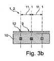
図3aおよび図3bは図1に基づく本発明の表示装置2の断面図を示し、表示装置1はカラー表示装置である。各図において、表示領域2の上面図の上に側面図が示されている。ただし、色同士を区別しよりよい図示を提供するためにここでは網掛けを用いている。3a and 3b show a cross-sectional view of a
2つの画素10が図3aに示されている。それぞれにおいて照明領域12が画素10に割り当てられ、複数の色が照明領域12を通して観察者に向けて発せられる。左側には、好ましくはストリップ状に配置された赤色(左上から右下への狭い網掛け)、緑色 (左下から右上への狭い網掛け)、青色(垂直の狭い網掛け)からなる画素10の成分、右側には、好ましくは約正方形に配置された赤色、緑色、青色および白色(網掛けなし)からなる画素10の成分、という画素10の成分の2つの可能性が示されている。左上から右下へ広く網掛けされた成分、ここでは非照明領域9は、好ましくは遮光性である。Two
図3bにおいて3つの照明領域12が割り当てられた画素10が示されていて、赤は第1の照明領域12を通して観察者に放射され、緑は第2の照明領域12を通して観察者に放射され、青は第3の照明領域12を通して観察者に放射されることができる。隣接する照明領域12の重心間の間隔11.1は観察者50の分解能よりも小さい間隔11の1/3である。In FIG. 3
図4aから図7bは本発明の原理に従った表示領域2の二次元構造が、表示領域2全体の70%より多い割合の非照明領域9を備えるために、異なる方法でどのように得られるかを示す。光学軸は各図において一点鎖線で描かれており、部分的に、対応する光源21の好ましい光パターンや色が光学軸の下端に示されている。そして好ましくは光学軸の上端に照明領域12上に結果として生じる光パターンや色が示されている。FIGS. 4a to 7b show how the two-dimensional structure of the
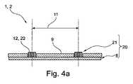
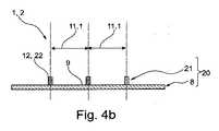
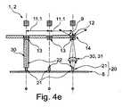
図4aから図4eは図3aまたは図3bに基づく本発明の表示装置1の断面の部分図を示す。表示装置1は複数の光源21が配置された基板8を備えた照明装置20を有し、好ましくは、光源21は小さな光源21(例:VCSEL)、すなわち好ましくは活性照明領域22の表面領域が対応する照明領域12の表面領域以下である光源21である。図4aおよび4dは多色の、すなわち異なる波長、たとえば赤、緑、青の割合、を有する光の、異なる可変な割合を放射するように設定された光源21を示している。図4b、図4c、および図4eは単色の、すなわち非可変波長範囲または異なる波長の固定された混合を放射する光源21を示している。4a to 4e show a partial view of a cross section of a
図4aにおいて、照明領域12はそれぞれに光源21の1つによって形成されている。表示領域2の非照明領域9は光源21間の充填材料の領域によって形成され、図4bにおいてもこれと同様に備えられてもよい。図4bにおいて、照明領域12はそれぞれに光源21の1つによって形成されている。表示領域2の非照明領域9は基板8の領域によって形成され、図4aにおいてもこれと同様に備えられてもよい。したがって図4aおよび図4bにおいて同様に、それぞれの光源21の活性照明領域22は表示領域2の照明領域12である。こうして少ない構成要素によって表示装置を製造することが可能になるが、有利には、これには定性的に非常に高品質で明るく正確な寸法の光源が使用されることが意図される。In FIG. 4 a, the
図4cにおいて、照明領域12はそれぞれに光源21の1つによって照明されることが可能な透明カバー素子によって形成される。表示領域2の非照明領域9は光源21間の充填材料の領域によって形成されている。各光源21は発光材料層と電子ビームを放射することによって発光材料層が能動的に光るように設定された電子エミッタとを有する。発光材料層はまた、一方向から到達する照射エネルギーを複数の方向に分配することから、散乱素子とみなされてもよい。電子エミッタと発光材料層との間にはそれぞれの場合において真空セル内に真空が存在する。 In FIG. 4 c the
この有利な点は、照明領域間の大きな中間領域という進歩的な原則のために、真空セルを非常に好適にシーリングすることがまた可能になることである。The advantage of this is that it also makes it possible to seal the vacuum cell very well due to the progressive principle of a large intermediate area between the illumination areas.
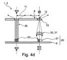
図4dにおいて、照明領域12はそれぞれに、光源21の1つによって照明されることのできる光学散乱素子13(左下から右上への広い網掛け―このタイプの網掛けは好ましくはこのように網掛けされた構成要素、たとえばまた後出のレンズは、好ましくは実質的にカラーフィルタを備えず、透明であることを意味する)によって形成されている。表示領域2の非照明領域9は、散乱素子12の高さにおいて光源21間の充填材料の表面によって形成されている。左にビーム整形装置30としていわゆるライトガイド(例:グラスファイバー)であって集光器31としても働くライトガイドを備えた実施形態、右に集光器31としてレンズを備えた実施形態の2つの可能な実施形態が示されている。照明領域12上に結果として生じる光パターンが、左には照明領域22の光パターンとほぼ同じ大きさで、右にはいくらか小さく上部に示されている。加えて、結果として生じる光パターンは、好ましくは色が完全に混合した状態でより拡散しており、それは散乱素子13のために起こるが図面では有利に表現することはできない。これにより、散乱照射が得られるが同時に散乱素子13へ向かう光束も得られる。
図4eにおいて、照明領域12はそれぞれ、光源21の1つによって照明されることができる光学カラーフィルタ素子14によって形成されている。表示領域2の非照明領域9はカラーフィルタ素子14の高さにおいて光源21間の充填材料の表面によって形成されている。各光源21は、UV光線を放射することによって発光材料層、ここではたとえば散乱素子13としても機能する発光材料層、が能動的に光るように設定されたUVエミッタを有する。こうして異なる色、ここではRGB、はカラーフィルタ素子14を通してたとえば量子ドットによって受け取られる。さらに、左と右に図4dと同様にビーム整形素子30を備えた実施形態、そして中央にビーム整形素子30なしの変型という3つの可能な実施形態を示す。In FIG. 4 d, the
In FIG. 4 e, the
好ましくは、図4dおよび4eにおいて、たとえば図6aと同様にコリメータ34はビーム整形装置30の一部である。Preferably, in FIGS. 4 d and 4 e, for example as in FIG. 6 a, the
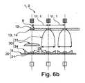
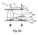
図5aから図6dは図3aまたは図3bに基づく本発明の表示装置1の断面を示している。図4aから図4eと比較して、これらはより大きな光源21と、特に各図において照明装置20と表示領域2との間に配置された光学ビーム整形装置30とを有しており、照明領域12は各ビーム整形装置30に割り当てられていて、ビーム整形装置30は各図において照明装置20からそれぞれの照明領域12に向かって光を集めるように設定されている。光源21の活性照明領域22のそれぞれは、表示領域2の照明領域12の個々の表面領域よりも大きな表面領域を有する。表示装置1はそれぞれに、照明装置20と表示領域2との間に配置された光学ビーム整形装置30を有し、照明領域12は各ビーム整形装置30に割り当てられていて、ビーム整形装置30は各図において照明装置20から個々の照明領域12に向かって光を集めるように設定されている。光学ビーム整形装置30のそれぞれは、光学コリメータ34(例:半球状のコリメータレンズ)と曲面状の反射表面を備えた光学集光器31とを有し、各光学コリメータ34は照明装置20からの光の伝達方向に関して集光器31の前に配置され、その結果光はまず実質的に平行化されその後集められる。集光器31として、一方では複合放物面集光器(CPC)(2つの向かい合う曲面状、好ましくは放物線状の曲面状反射表面によって表現される。また図5cにおける斜視図でも示される)を備え、代替としては集光レンズ31(たとえば図6aの右)を備える。コリメータ34としては、一方ではプリズムコリメータ34(ピラミッド構造で示される)、または代替としてはリフレクター34(図6aから図6dにあるような)が存在する。5a to 6d show a cross section of a
図5a、図5bおよび図5dにおいて、表示装置1はほぼランバートラジエータである光源21を有する。図5aにおいて、各照明領域12は照明装置20によって照明されることができる光学散乱素子13によって形成されている。表示領域2の非照明領域9は散乱素子13間に配置された充填材料の表面によって形成されていて、充填材料はここでは領域として示されているが、隣接するビーム整形素子30間の中間空間を完全に充填することもまた可能である。光源は多色であって光源またはその活性照明領域は照明領域12の重心間の間隔11の50%よりも大きい長さを有する。CPC31は入力部32と出力部33とを有し(図5cも参照のこと)、入力部32は出力部33よりも大きな表面領域を有し、出力部33は照明領域12および表示領域2に対向し、入力部32は照明装置20に対向する。CPCはプリズムコリメータ34の光学出力角36よりも小さい最大30°から10°、好ましくは20°、の光学入力角37を有する。したがって光学損失35を可能な限り最小化することができる。コリメータ34と集光器31との組み合わせによって照明領域12に対する効果的な光の集中が生じる。加えて、非結像光学システムとしてのCPCによって非常に均質的な色の混合が達成され、それは白色出力光パターンによって示される。散乱素子13により広い視野角が可能になる。光のビーム経路は破線矢印で示される。図5bにおいて、図5aの表示装置の変型が示されており、光源21の長さは間隔11の50%よりも小さいが、照明領域12の長さよりも大きい。図5dにおいては、図5aとは異なり、光源は単色であって照明領域12はそれぞれに光学カラーフィルタ素子によって形成されており、光学カラーフィルタ素子は同時に散乱素子13であり、照明装置20によって照明されることができる。さらに、間隔11の1/3である間隔11.1が照明領域12の間に結果として生じる。In Figures 5a, 5b and 5d, the
図6a、図6b、図6cおよび図6dにおいて、表示装置1は面積において(たとえば光源の活性照明領域に関して)照明領域12と同じ大きさかより大きい光源21を有する。他の点では図6aは図5aに類似しているが、図5aとは異なり図6aには放物線状リフレクターとして光源21を取り囲むコリメータ34が示される。照明装置20からの光の伝達方向に関して、光学コリメータ34はここでも集光器31の前に配置されその結果光はまず実質的に平行化されその後集められる。変型として、集光器31としてCPCに代わる集光レンズ、ここでは非結像集光レンズ、とともにRGBW光源が右に示される。集光レンズは同じく照明領域12を透過する光の均質化を良好に行う。図6bは図6aに類似しており、光源21は単色であって照明領域12のそれぞれは光学カラーフィルタ素子によって形成されていて、光学カラーフィルタ素子は同時に散乱素子13であって、照明装置20によって照明されることができる。さらに、間隔11の1/3である間隔11.1が照明領域12の間に結果として生じる。図6cは図6aに似ており、光源21は単色であって、ここでは白であり、カラーフィルタ素子14は光源21上に直接配置されている。さらに、右には結像集光レンズ31を備えた可能な実施形態が示される。図6dは図6aに類似しており、光源21は単色であって、ここではたとえば実質的に青色および/またはUV放射光源である。照明領域12のそれぞれは照明装置20によって照明されることができる光学カラーフィルタ素子14によって形成されている。各光源21は、青色および/またはUV光線を放射することで、ここでは散乱素子13として作用する発光材料層が能動的に光るように設定された青色および/またはUVエミッタを有する。異なる色、ここではRGB、がこうしてカラーフィルタ素子14を通して受け取られる。さらに、間隔11の1/3である間隔11.1が照明領域12の間に結果として生じる。カラーフィルタ素子14(例:量子ドット)が光源21上に直接配置される。6a, 6b, 6c and 6d, the
全ての示された実施形態において、好ましくは非照明領域9、好ましくは全表示領域2、は50%未満の拡散反射および/または鏡面反射の反射率を有する。この目的により、好ましくは非照明領域9は暗色を有するか黒であり、および/または0.2μmから 1.0μmの範囲の平均粗さ指数を有し、および/または反射防止膜によって被膜されている。電子補償装置が加えて存在することが好ましく、それによって周囲の明るさに応じて黒画像画素の表現を適合させるように照明領域12の最小輝度を自動設定することが可能になる。In all the illustrated embodiments, preferably the non-illuminated area 9, preferably the
本発明によって、表示装置の品質における革新的な改良が達成される。照明領域間にある非照明領域を可能な限り大きくする、たとえば全表示領域における非照明領域の割合が少なくとも70%である、という設計の原則によって画像品質は向上する。コントラストはその結果改良され多くのエネルギーの節約が可能になり、これは特に携帯式装置にとっては非常に重要である。低反射率(鏡面または拡散)の非照明領域を加えて備えることで黒画像成分はまた、黒を保持することになる。明るい画像部をより明るくすることができるように、また照明領域の表面割合の減少による輝度の損失を補償するために、特別に強い光源(例:レーザ、マイクロLED、またはマイクロOLEDS)が用いられるか、観察者の視点からみて表示装置の背後にある特別なビーム整形装置によって照明領域に向けた光の集中、その後の輝度の上昇が達成される。その結果、輝度の平均値は通常の表示装置のものと類似しながらも、かつ周囲光によるより良いコントラストおよびより低いエネルギー消費が得られる。
The present invention achieves an innovative improvement in the quality of the display. The image quality is improved by the design principle that the non-illuminated area between the illuminated areas is as large as possible, for example the percentage of non-illuminated areas in the whole display area is at least 70%. The contrast is then improved and a lot of energy saving is possible, which is very important especially for portable devices. The black image component will also retain black with the addition of a low reflectance (specular or diffuse) non-illuminated area. Specially strong light sources (eg lasers, micro LEDs or micro OLEDS) are used so that bright image areas can be made brighter and to compensate for the loss of brightness due to the reduction of the surface fraction of the illumination area Alternatively, a special beam shaping device behind the display from the observer's point of view achieves a concentration of light towards the illumination area and a subsequent increase in brightness. As a result, the mean value of the brightness is similar to that of a conventional display, but with better contrast and lower energy consumption due to ambient light.
1 表示装置
2 表示装置の表示領域
8 基板
9 非照明領域
10 画素
11 間隔
11.1 間隔11の1/3
12 照明領域
13 散乱素子
14 カラーフィルタ素子
20 照明装置
21 光源
22 光源の活性照明領域
30 光学ビーム整形装置
31 光学集光器
32 光学集光器の入力部
33 光学集光器の出力部
34 光学コリメータ
35 光学損失
36 光学コリメータの出力角
37 光学集光器の入力角
50 観察者
51 入射角
12
Claims (15)
Translated fromJapanese非照明領域と照明領域とからなる表示領域と、
を備える、表示装置であって、
前記表示領域における、前記照明領域の合計表面積は、前記表示領域の表面積の30%未満であり、
−隣接する前記照明領域の重心の間隔は、190μmよりも小さく、
−前記照明領域の直径は、25μm未満であり、
−それぞれの前記照明領域は、イメージの異なる画素を形成し、
−前記表示装置は、さらに、前記照明装置と、前記照明領域との間に配置された、光学ビーム整形装置を含み、
それぞれの前記光学ビーム整形装置は、異なる前記照明領域に割り当てられ、前記照明装置からの光を前記照明領域に導き、
前記光学ビーム整形装置は、前記照明装置からの光の全てを前記照明領域に向かって集光する少なくとも1つの曲面状または段状の反射表面を有する、
表示装置。A lighting device,
Adisplay area consisting of anon-illumination area and anillumination area ;
A display device comprising:
In thedisplay area, the total surface area of theillumination region is less than 30% of the surface area of thedisplay region,
The distance between the centers of gravity of the adjacentillumination areas is less than 190 μm,
- the diameter of thefront Symbolillumination area is less than 25 [mu] m,
Each saidillumination area forms a different pixel of the image;
- wherein the display device furtherincludes apre-Symbol illumination device, disposed between theillumination region, comprising an optical beam shaping device,
Each of the optical beam shaping device is assigned to different theillumination areaguideslight fromthe illumination device to theillumination region,
The optical beam shaping device comprises at least one curved or stepped reflective surface which condenses all the light from the illumination device towards the illumination area.
Displayequipment.
前記照明領域のそれぞれは、前記複数の光源の1つで照らされる、
請求項1から請求項9のいずれかに記載の表示装置。Includesthe illumination device having a substrate on which a plurality of light sources are arranged,
Each ofthe illumination area is illuminated by one of said plurality of light sources,
Displayequipment as claimed in any one of claims 1 to9.
Applications Claiming Priority (5)
| Application Number | Priority Date | Filing Date | Title |
|---|---|---|---|
| DE102014002272 | 2014-02-19 | ||
| DE102014002272.2 | 2014-02-19 | ||
| DE102014009677.7ADE102014009677A1 (en) | 2014-02-19 | 2014-06-30 | Display device with improved contrast |
| DE102014009677.7 | 2014-06-30 | ||
| PCT/EP2015/000354WO2015124291A1 (en) | 2014-02-19 | 2015-02-18 | Display device with better contrast |
Publications (3)
| Publication Number | Publication Date |
|---|---|
| JP2017515137A JP2017515137A (en) | 2017-06-08 |
| JP2017515137A5 JP2017515137A5 (en) | 2018-03-29 |
| JP6535339B2true JP6535339B2 (en) | 2019-06-26 |
Family
ID=53758701
Family Applications (1)
| Application Number | Title | Priority Date | Filing Date |
|---|---|---|---|
| JP2016552586AActiveJP6535339B2 (en) | 2014-02-19 | 2015-02-18 | Display device with improved contrast |
Country Status (7)
| Country | Link |
|---|---|
| US (1) | US10127890B2 (en) |
| EP (1) | EP3108285B1 (en) |
| JP (1) | JP6535339B2 (en) |
| KR (1) | KR102329594B1 (en) |
| CN (1) | CN106030370B (en) |
| DE (1) | DE102014009677A1 (en) |
| WO (1) | WO2015124291A1 (en) |
Families Citing this family (7)
| Publication number | Priority date | Publication date | Assignee | Title |
|---|---|---|---|---|
| GB201420860D0 (en)* | 2014-11-24 | 2015-01-07 | Infiniled Ltd | Micro-LED device |
| WO2017148491A1 (en)* | 2016-03-02 | 2017-09-08 | Pa.Cotte Family Holding Gmbh | Method for producing a display device, and display device |
| DE102017107303A1 (en)* | 2017-04-05 | 2018-10-11 | Osram Opto Semiconductors Gmbh | DEVICE FOR DISPLAYING AN IMAGE |
| JP7249787B2 (en)* | 2018-02-28 | 2023-03-31 | シャープ株式会社 | Display element and display device |
| EP3599644B1 (en)* | 2018-07-26 | 2020-08-19 | PA.Cotte Family Holding GmbH | Multifunctional display |
| TWI678010B (en)* | 2018-12-07 | 2019-11-21 | 友達光電股份有限公司 | Display array panel and display device |
| JP2025532565A (en)* | 2022-09-19 | 2025-10-01 | インドリオ テクノロジーズ インコーポレイテッド | Multipass palladium hydride optical cavity for hydrogen detection. |
Family Cites Families (38)
| Publication number | Priority date | Publication date | Assignee | Title |
|---|---|---|---|---|
| TW289864B (en)* | 1994-09-16 | 1996-11-01 | Micron Display Tech Inc | |
| JPH1185056A (en)* | 1997-09-10 | 1999-03-30 | Yazaki Corp | Multi-function display device |
| US6337675B1 (en)* | 1997-10-30 | 2002-01-08 | Ut Automotive Dearborn, Inc | Display system with automatic and manual brightness control |
| US6040936A (en)* | 1998-10-08 | 2000-03-21 | Nec Research Institute, Inc. | Optical transmission control apparatus utilizing metal films perforated with subwavelength-diameter holes |
| US7023511B1 (en)* | 1999-07-20 | 2006-04-04 | Lg. Philips Lcd Co., Ltd. | Transflective liquid crystal display device |
| US6456354B2 (en)* | 1999-08-06 | 2002-09-24 | Rainbow Displays, Inc. | Design features optimized for tiled flat-panel displays |
| US6410942B1 (en)* | 1999-12-03 | 2002-06-25 | Cree Lighting Company | Enhanced light extraction through the use of micro-LED arrays |
| JP4067052B2 (en) | 2001-07-25 | 2008-03-26 | キヤノン株式会社 | Display device |
| JP2002236283A (en)* | 2001-12-03 | 2002-08-23 | Omron Corp | Image display device and manufacturing method therefor and microlens array substrate and manufacturing method therefor |
| JP4208526B2 (en)* | 2002-09-12 | 2009-01-14 | キヤノン株式会社 | ORGANIC EL DISPLAY DEVICE AND ELECTRONIC DEVICE HAVING THE DISPLAY DEVICE |
| JP2006525669A (en)* | 2003-05-02 | 2006-11-09 | ユニバーシティ・カレッジ・コークーナショナル・ユニバーシティ・オブ・アイルランド,コーク | Light emitting diode and manufacturing method thereof |
| GB2404774B (en)* | 2003-08-07 | 2007-02-14 | Pelikon Ltd | Electroluminescent displays |
| US6822709B1 (en)* | 2003-09-23 | 2004-11-23 | Toppoly Optoelectronics Corp. | Transflective display device |
| WO2005059636A1 (en) | 2003-12-17 | 2005-06-30 | Koninklijke Philips Electronics N.V. | Display device |
| TWI243625B (en)* | 2004-05-04 | 2005-11-11 | Toppoly Optoelectronics Corp | Organic light-emitting display structure |
| JP2005352138A (en)* | 2004-06-10 | 2005-12-22 | Fuji Photo Film Co Ltd | Cellulose acylate film, polarizing plate and liquid crystal display device |
| US7522236B2 (en)* | 2005-09-23 | 2009-04-21 | Apple Inc. | Cosmetically uniform reflective border area in a transflective display |
| US7884315B2 (en) | 2006-07-11 | 2011-02-08 | Apple Inc. | Invisible, light-transmissive display system |
| US7498735B2 (en) | 2005-10-18 | 2009-03-03 | Eastman Kodak Company | OLED device having improved power distribution |
| US8477125B2 (en)* | 2005-12-21 | 2013-07-02 | Samsung Display Co., Ltd. | Photo sensor and organic light-emitting display using the same |
| US20070222922A1 (en) | 2006-03-22 | 2007-09-27 | Eastman Kodak Company | Graded contrast enhancing layer for use in displays |
| CN101554059B (en)* | 2006-12-07 | 2011-06-08 | 皇家飞利浦电子股份有限公司 | An ambient lighting system for a display device |
| JPWO2009001508A1 (en)* | 2007-06-26 | 2010-08-26 | シャープ株式会社 | Liquid crystal display device and method of manufacturing liquid crystal display device |
| JP2009157234A (en)* | 2007-12-27 | 2009-07-16 | Nof Corp | Antiglare antireflection film and liquid crystal display provided with the same |
| US8513685B2 (en)* | 2008-11-13 | 2013-08-20 | 3M Innovative Properties Company | Electrically pixelated luminescent device incorporating optical elements |
| CN102803823B (en)* | 2009-06-15 | 2015-09-23 | 夏普株式会社 | Lighting device, display unit and radiovisor |
| WO2011025171A2 (en)* | 2009-08-27 | 2011-03-03 | Lg Electronics Inc. | Optical assembly, backlight unit, and display device |
| US9341887B2 (en)* | 2009-09-11 | 2016-05-17 | Dolby Laboratories Licensing Corporation | Displays with a backlight incorporating reflecting layer |
| JP2011170058A (en)* | 2010-02-18 | 2011-09-01 | Canon Inc | Black matrix, manufacturing method thereof, and image display apparatus using the same |
| US9765934B2 (en)* | 2011-05-16 | 2017-09-19 | The Board Of Trustees Of The University Of Illinois | Thermally managed LED arrays assembled by printing |
| JP2013125266A (en)* | 2011-12-16 | 2013-06-24 | Asahi Glass Co Ltd | Optical filter for display and display device |
| US9557597B2 (en) | 2011-12-27 | 2017-01-31 | Sharp Kabushiki Kaisha | Liquid crystal display device, light control film, and display device |
| US9472594B2 (en)* | 2012-02-10 | 2016-10-18 | Oculus Vr, Llc | Light emitting diode chip |
| EP2815436B1 (en)* | 2012-02-16 | 2017-12-20 | Oculus VR, LLC | Micro-led array with filters |
| US9159700B2 (en)* | 2012-12-10 | 2015-10-13 | LuxVue Technology Corporation | Active matrix emissive micro LED display |
| US9252375B2 (en)* | 2013-03-15 | 2016-02-02 | LuxVue Technology Corporation | Method of fabricating a light emitting diode display with integrated defect detection test |
| US9768345B2 (en)* | 2013-12-20 | 2017-09-19 | Apple Inc. | LED with current injection confinement trench |
| US10066819B2 (en)* | 2015-12-09 | 2018-09-04 | X-Celeprint Limited | Micro-light-emitting diode backlight system |
- 2014
- 2014-06-30DEDE102014009677.7Apatent/DE102014009677A1/ennot_activeWithdrawn
- 2015
- 2015-02-18WOPCT/EP2015/000354patent/WO2015124291A1/enactiveApplication Filing
- 2015-02-18KRKR1020167025545Apatent/KR102329594B1/enactiveActive
- 2015-02-18USUS15/120,125patent/US10127890B2/enactiveActive
- 2015-02-18CNCN201580009611.5Apatent/CN106030370B/enactiveActive
- 2015-02-18JPJP2016552586Apatent/JP6535339B2/enactiveActive
- 2015-02-18EPEP15705501.3Apatent/EP3108285B1/enactiveActive
Also Published As
| Publication number | Publication date |
|---|---|
| EP3108285C0 (en) | 2024-01-10 |
| EP3108285B1 (en) | 2024-01-10 |
| KR20160123366A (en) | 2016-10-25 |
| CN106030370A (en) | 2016-10-12 |
| EP3108285A1 (en) | 2016-12-28 |
| CN106030370B (en) | 2020-05-01 |
| KR102329594B1 (en) | 2021-11-19 |
| WO2015124291A1 (en) | 2015-08-27 |
| DE102014009677A1 (en) | 2015-08-20 |
| US10127890B2 (en) | 2018-11-13 |
| JP2017515137A (en) | 2017-06-08 |
| US20170076693A1 (en) | 2017-03-16 |
Similar Documents
| Publication | Publication Date | Title |
|---|---|---|
| JP6535339B2 (en) | Display device with improved contrast | |
| JP6553280B2 (en) | Screen for free and limited operation modes | |
| US20250291105A1 (en) | Illumination apparatus | |
| JP6535340B2 (en) | Display device | |
| TWI669555B (en) | Dual view zone backlight, dual-mode display, and method | |
| US9726948B2 (en) | Image display device | |
| CN102207576B (en) | Light supply apparatus and stereoscopic display device | |
| ES2865127T3 (en) | Directional backlight | |
| RU2669497C2 (en) | Glazing comprising transparent screen | |
| CN202649645U (en) | Liquid crystal display panel and display device | |
| WO2013011813A1 (en) | Front light and method for producing same, reflective display device provided with front light, and electronic equipment provided with reflective display device | |
| US20210116758A1 (en) | Backlight module and display device | |
| JP2014029356A (en) | Light source device, display device, and electronic apparatus | |
| JP2012226294A (en) | Light source device, display, and electronic apparatus | |
| BR112014019365B1 (en) | METHOD TO ILLUMINATE AN ARRAY OF TRANSPARENT PIXELS OF IMAGE FORMATION OF A SCREEN, LIGHTING DEVICE, AND SCREEN FOR PRESENTING IMAGES | |
| CN107193069A (en) | A kind of grating and double vision display device | |
| TWI589965B (en) | Switchable lighting device and use thereof | |
| TWI740584B (en) | Collimated backlight, electronic display, and method employing an absorption collimator | |
| JP4111947B2 (en) | Manufacturing method of laser light screen | |
| WO2014148099A1 (en) | Light source device, display apparatus, and electronic apparatus | |
| WO2014112258A1 (en) | Display device and electronic device | |
| JP6171625B2 (en) | Display unit and display device | |
| JP3683420B2 (en) | Front panel for display device | |
| KR20130101249A (en) | Stacked structure of an optical film for modifying an led panel adapted into a high luminescent lcd | |
| JP2020009742A (en) | Display device |
Legal Events
| Date | Code | Title | Description |
|---|---|---|---|
| A521 | Request for written amendment filed | Free format text:JAPANESE INTERMEDIATE CODE: A523 Effective date:20180216 | |
| A621 | Written request for application examination | Free format text:JAPANESE INTERMEDIATE CODE: A621 Effective date:20180216 | |
| A131 | Notification of reasons for refusal | Free format text:JAPANESE INTERMEDIATE CODE: A131 Effective date:20190108 | |
| A521 | Request for written amendment filed | Free format text:JAPANESE INTERMEDIATE CODE: A523 Effective date:20190403 | |
| TRDD | Decision of grant or rejection written | ||
| A01 | Written decision to grant a patent or to grant a registration (utility model) | Free format text:JAPANESE INTERMEDIATE CODE: A01 Effective date:20190514 | |
| A61 | First payment of annual fees (during grant procedure) | Free format text:JAPANESE INTERMEDIATE CODE: A61 Effective date:20190531 | |
| R150 | Certificate of patent or registration of utility model | Ref document number:6535339 Country of ref document:JP Free format text:JAPANESE INTERMEDIATE CODE: R150 | |
| R250 | Receipt of annual fees | Free format text:JAPANESE INTERMEDIATE CODE: R250 | |
| R250 | Receipt of annual fees | Free format text:JAPANESE INTERMEDIATE CODE: R250 | |
| S111 | Request for change of ownership or part of ownership | Free format text:JAPANESE INTERMEDIATE CODE: R313114 | |
| R250 | Receipt of annual fees | Free format text:JAPANESE INTERMEDIATE CODE: R250 | |
| R360 | Written notification for declining of transfer of rights | Free format text:JAPANESE INTERMEDIATE CODE: R360 | |
| R360 | Written notification for declining of transfer of rights | Free format text:JAPANESE INTERMEDIATE CODE: R360 | |
| R371 | Transfer withdrawn | Free format text:JAPANESE INTERMEDIATE CODE: R371 | |
| R250 | Receipt of annual fees | Free format text:JAPANESE INTERMEDIATE CODE: R250 |