JP6534926B2 - Speaker identification method, speaker identification device and speaker identification system - Google Patents
Speaker identification method, speaker identification device and speaker identification systemDownload PDFInfo
- Publication number
- JP6534926B2 JP6534926B2JP2015522523AJP2015522523AJP6534926B2JP 6534926 B2JP6534926 B2JP 6534926B2JP 2015522523 AJP2015522523 AJP 2015522523AJP 2015522523 AJP2015522523 AJP 2015522523AJP 6534926 B2JP6534926 B2JP 6534926B2
- Authority
- JP
- Japan
- Prior art keywords
- speaker
- voice
- image
- voice signal
- unit
- Prior art date
- Legal status (The legal status is an assumption and is not a legal conclusion. Google has not performed a legal analysis and makes no representation as to the accuracy of the status listed.)
- Active
Links
Images


Classifications
- G—PHYSICS
- G06—COMPUTING OR CALCULATING; COUNTING
- G06F—ELECTRIC DIGITAL DATA PROCESSING
- G06F3/00—Input arrangements for transferring data to be processed into a form capable of being handled by the computer; Output arrangements for transferring data from processing unit to output unit, e.g. interface arrangements
- G06F3/16—Sound input; Sound output
- G—PHYSICS
- G10—MUSICAL INSTRUMENTS; ACOUSTICS
- G10L—SPEECH ANALYSIS TECHNIQUES OR SPEECH SYNTHESIS; SPEECH RECOGNITION; SPEECH OR VOICE PROCESSING TECHNIQUES; SPEECH OR AUDIO CODING OR DECODING
- G10L17/00—Speaker identification or verification techniques
- G—PHYSICS
- G10—MUSICAL INSTRUMENTS; ACOUSTICS
- G10L—SPEECH ANALYSIS TECHNIQUES OR SPEECH SYNTHESIS; SPEECH RECOGNITION; SPEECH OR VOICE PROCESSING TECHNIQUES; SPEECH OR AUDIO CODING OR DECODING
- G10L15/00—Speech recognition
- G—PHYSICS
- G10—MUSICAL INSTRUMENTS; ACOUSTICS
- G10L—SPEECH ANALYSIS TECHNIQUES OR SPEECH SYNTHESIS; SPEECH RECOGNITION; SPEECH OR VOICE PROCESSING TECHNIQUES; SPEECH OR AUDIO CODING OR DECODING
- G10L15/00—Speech recognition
- G10L15/22—Procedures used during a speech recognition process, e.g. man-machine dialogue
- G—PHYSICS
- G10—MUSICAL INSTRUMENTS; ACOUSTICS
- G10L—SPEECH ANALYSIS TECHNIQUES OR SPEECH SYNTHESIS; SPEECH RECOGNITION; SPEECH OR VOICE PROCESSING TECHNIQUES; SPEECH OR AUDIO CODING OR DECODING
- G10L15/00—Speech recognition
- G10L15/24—Speech recognition using non-acoustical features
- G—PHYSICS
- G10—MUSICAL INSTRUMENTS; ACOUSTICS
- G10L—SPEECH ANALYSIS TECHNIQUES OR SPEECH SYNTHESIS; SPEECH RECOGNITION; SPEECH OR VOICE PROCESSING TECHNIQUES; SPEECH OR AUDIO CODING OR DECODING
- G10L17/00—Speaker identification or verification techniques
- G10L17/22—Interactive procedures; Man-machine interfaces
- G—PHYSICS
- G10—MUSICAL INSTRUMENTS; ACOUSTICS
- G10L—SPEECH ANALYSIS TECHNIQUES OR SPEECH SYNTHESIS; SPEECH RECOGNITION; SPEECH OR VOICE PROCESSING TECHNIQUES; SPEECH OR AUDIO CODING OR DECODING
- G10L15/00—Speech recognition
- G10L15/24—Speech recognition using non-acoustical features
- G10L15/25—Speech recognition using non-acoustical features using position of the lips, movement of the lips or face analysis
Landscapes
- Engineering & Computer Science (AREA)
- Physics & Mathematics (AREA)
- Health & Medical Sciences (AREA)
- Audiology, Speech & Language Pathology (AREA)
- Human Computer Interaction (AREA)
- Acoustics & Sound (AREA)
- Multimedia (AREA)
- Computational Linguistics (AREA)
- Theoretical Computer Science (AREA)
- General Health & Medical Sciences (AREA)
- General Engineering & Computer Science (AREA)
- General Physics & Mathematics (AREA)
- Two-Way Televisions, Distribution Of Moving Picture Or The Like (AREA)
- User Interface Of Digital Computer (AREA)
Description
Translated fromJapanese本開示は、話者を識別して表示部に識別した話者を表す話者画像を表示する話者識別方法、話者識別装置及び話者識別システムに関するものである。 The present disclosure relates to a speaker identification method, a speaker identification device, and a speaker identification system for identifying a speaker and displaying a speaker image representing the speaker identified on the display unit.
従来、話者識別および音声認識装置として、音声信号中に含まれる情報を用いて話者を識別する方法が提案されている。特許文献1では、会話内容を音声認識により文字データで記録する際に、一文字毎にタイムスタンプと音声から抽出する音声特徴を合わせて記録し、同一話者の発言内容を色や表示位置で区分して表示する方法が開示されている。これにより話者別に識別可能な会議システムを実現している。 Heretofore, as a speaker identification and speech recognition apparatus, a method has been proposed for identifying a speaker using information contained in a speech signal. In
また、特許文献2では、音声データを文字画像データに変換し、発声順に連なって移動する文字列からなる表示方法について開示されている。これにより画像と文字により情報が重層的に理解できる表示方法を実現している。 Further,
しかしながら、従来の構成において、更なる改善が必要であった。 However, in the conventional configuration, further improvement is required.
上記課題を解決するため、本開示の一態様は、表示部の周辺に位置する話者の音声を識別し識別結果を前記表示部に表示する話者識別システムにおける話者識別方法であって、
前記話者識別システムは、複数の話者の音声に基づきそれぞれ生成された複数の登録音声信号と、前記複数の登録音声信号にそれぞれ対応付けられ前記複数の話者をそれぞれ表す複数の話者画像とを保存するデータベースを含み、
前記表示部の周辺に位置する話者の音声を取得し、
前記取得された話者の音声から話者音声信号を生成し、
前記データベースに保存されている複数の登録音声信号のうち、前記生成された話者音声信号に対応する登録音声信号を識別し、
前記識別された登録音声信号に対応付けて前記データベースに保存されている前記話者画像を、少なくとも前記話者音声信号を生成する元となった前記話者の音声が取得されている間、前記表示部に表示させるものである。In order to solve the above problems, one aspect of the present disclosure is a speaker identification method in a speaker identification system that identifies a voice of a speaker located around a display unit and displays an identification result on the display unit.
The speaker identification system includes a plurality of registered voice signals respectively generated based on voices of a plurality of speakers, and a plurality of speaker images respectively associated with the plurality of registered voice signals and respectively representing the plurality of speakers. Contains a database to store
Acquiring a voice of a speaker located around the display unit;
Generating a speaker voice signal from the voice of the obtained speaker;
Identifying a registered voice signal corresponding to the generated speaker voice signal among the plurality of registered voice signals stored in the database;
The speaker image stored in the database in association with the identified registered voice signal is at least while the voice of the speaker from which the speaker voice signal is generated is acquired. It is displayed on the display unit.
本態様によれば、更なる改善を図ることができる。 According to this aspect, further improvement can be achieved.
(本開示の基礎となった知見)
家庭内の機器から使用状況、又はその機器を使用しているユーザの音声情報等を取得し、この取得した情報に基づいてユーザにサービスを提供するシステムが検討されている。しかし、ユーザにとって機器の使用状況又は音声情報は、個人情報に類する情報としての側面がある。よって、もし取得した機器の使用状況又は音声情報が可視化されないまま利用されると、どのように取得した情報が利用されているのかが不明確であり、ユーザにとって抵抗があると考えられる。よって、ユーザの抵抗を軽減するために、取得した情報を可視化して表示するシステムを開発する必要がある。(Findings that formed the basis of this disclosure)
A system has been considered in which a usage status or voice information of a user who is using the device is acquired from a device in the home, and a service is provided to the user based on the acquired information. However, for the user, the usage status of the device or the voice information has an aspect as information similar to personal information. Therefore, if the acquired device use status or voice information is used without being visualized, it is unclear how the acquired information is used, and it is considered that the user has resistance. Therefore, in order to reduce the resistance of the user, it is necessary to develop a system that visualizes and displays the acquired information.
更に、機器が取得した情報に誤検出がある場合は、誤検出の情報を可視化すると、ユーザに対してさらに不快感を与えてしまう。よって、取得した情報を可視化して表示しつつ、誤検出があった場合には、誤検出に基づき可視化された情報をユーザの操作で簡易に修正可能であることが好ましい。 Furthermore, when there is a false detection in the information acquired by the device, if the false detection information is visualized, the user may be further offended. Therefore, while visualizing and displaying the acquired information, it is preferable that the information visualized based on the erroneous detection can be easily corrected by the operation of the user when there is an erroneous detection.
また、ユーザから取得した情報を表示する装置として、わざわざ取得した情報を表示するためだけの専用表示機器を家庭内に配置することは、コストがかかる点及び設置場所を要してしまう点で、好ましくない。そこで例えば家庭内におけるテレビ受像機(以下、「テレビ」という)などの、本来、取得した情報の結果を表示することが目的ではない表示装置上に表示することが考えられる。テレビのような表示装置の場合、受信したテレビ放送の映像を表示画面に表示する必要がある。したがって、テレビ放送以外の取得した情報をテレビの表示画面上に表示する方法に関しては検討が必要である。一方で、上記したようにユーザにとっての抵抗感を減らすため、音声認識の結果は簡単に、かつ即座に確認できることが好ましい。 In addition, as a device for displaying information acquired from the user, placing a dedicated display device only for displaying the acquired information in the house in a home is costly and requires an installation place. Not desirable. Therefore, for example, it is conceivable to display on a display device which is originally not intended to display the result of the acquired information, such as a television receiver (hereinafter referred to as "television") in the home. In the case of a display device such as a television, it is necessary to display the video of the received television broadcast on the display screen. Therefore, it is necessary to study how to display acquired information other than television broadcast on the display screen of the television. On the other hand, it is preferable that the result of speech recognition can be confirmed easily and immediately in order to reduce resistance to the user as described above.
さらに、例えばテレビの表示画面上に取得した音声情報を表示する場合、テレビの周辺には不特定多数の人が存在する可能性が高い。それら複数の人の音声情報をテレビの表示画面上に、即座に明確かつ簡潔に表示し、修正まで可能なシステムに関しては、従来より検討がされていない。 Furthermore, for example, when displaying the acquired audio information on the display screen of the television, there is a high possibility that an unspecified number of people are present around the television. There has been no study on a system that can immediately and clearly display the voice information of the plurality of persons on the display screen of the television and can correct it.
特許文献1,2に記載の技術のように、話者識別および音声認識の結果を文字で表示する際には、複数の人が会話している場合又は話者が連続して複数回にわたり発声した場合において、文字列の表示画像が複雑になり、誰が識別されて表示されているのか明確にわかりづらい。また、まれに話者識別の結果が異なって表示された場合に、簡易な修正方法がないという問題点があった。 As in the techniques described in
また、特許文献1,2に記載の技術では、例えばテレビなど、本来、音声認識の結果を表示することが目的ではない表示装置上に、音声認識の結果を表示する際の、表示方法に関しては、十分な検討がされていない。 Moreover, in the techniques described in
例えば特許文献1による技術では、単に、会議等の内容を記録する会話記録装置であって、音声認識結果を一文字毎にタイムスタンプおよび音声から抽出する特徴量を合わせて記録し、記録後にクラスタリング処理を行い、会話に参加していた人数と、各話者の音声特徴を求め、各話者の音声特徴と記録データを比較して話者を判別し、同一話者の発言内容を色や表示位置で区分して表示するものである。そのため、特許文献1に記載の技術では、複数話者が発声した場合、表示内容を簡易に且つ間違えなく確認して内容を修正することは困難であると考えられる。また、取得した音声情報を表示する例が示されているが、画面全体に音声情報を表示する例しか示されていない。よって、特許文献1に記載の技術には、テレビなど、本来音声認識の結果を表示することが目的ではない表示装置上に、音声情報を表示することに関しては課題の認識すらない。 For example, the technology according to
また、特許文献2による技術は、音声信号に含まれる言語情報と音声特性情報との双方を迅速かつ簡便に理解できる音声認識文字表示装置に関するものである。この技術では、単に文字画像データに変換し、発声順に連なって移動する文字列からなる表示方法について開示されている。特許文献2に記載の技術では、画像と文字により情報が重層的に理解できる表示方法を実現しているため、表示に誤りがあった際に、簡便に変更することは困難であると考えられる。 Further, the technique according to
本開示は、以上のような従来の話者識別および音声認識表示装置の課題を解決するものである。本開示の一態様により、複数の話者の音声情報を取得し、例えばテレビのような表示装置において、本来表示すべきコンテンツを表示しつつ、取得した音声情報を即座に明確かつ簡潔に表示することができる装置が提供される。さらには、本開示の一態様により、取得した情報に誤検出があった際等に、表示されている情報を簡易にユーザが修正可能な装置が提供される。 The present disclosure solves the problems of the conventional speaker identification and speech recognition display apparatus as described above. According to an aspect of the present disclosure, voice information of a plurality of speakers is obtained, and the obtained voice information is displayed clearly and concisely while displaying contents to be originally displayed on a display device such as a television. An apparatus capable of Furthermore, according to an aspect of the present disclosure, an apparatus is provided that allows the user to easily correct the displayed information, for example, when there is a false detection in the acquired information.
本開示の一態様は、
表示部の周辺に位置する話者の音声を識別し識別結果を前記表示部に表示する話者識別システムにおける話者識別方法であって、
前記話者識別システムは、複数の話者の音声に基づきそれぞれ生成された複数の登録音声信号と、前記複数の登録音声信号にそれぞれ対応付けられ前記複数の話者をそれぞれ表す複数の話者画像とを保存するデータベースを含み、
前記表示部の周辺に位置する話者の音声を取得し、
前記取得された話者の音声から話者音声信号を生成し、
前記データベースに保存されている複数の登録音声信号のうち、前記生成された話者音声信号に対応する登録音声信号を識別し、
前記識別された登録音声信号に対応付けて前記データベースに保存されている前記話者画像を、少なくとも前記話者音声信号を生成する元となった前記話者の音声が取得されている間、前記表示部に表示させるものである。One aspect of the present disclosure is
A speaker identification method in a speaker identification system for identifying a voice of a speaker located around a display unit and displaying an identification result on the display unit.
The speaker identification system includes a plurality of registered voice signals respectively generated based on voices of a plurality of speakers, and a plurality of speaker images respectively associated with the plurality of registered voice signals and respectively representing the plurality of speakers. Contains a database to store
Acquiring a voice of a speaker located around the display unit;
Generating a speaker voice signal from the voice of the obtained speaker;
Identifying a registered voice signal corresponding to the generated speaker voice signal among the plurality of registered voice signals stored in the database;
The speaker image stored in the database in association with the identified registered voice signal is at least while the voice of the speaker from which the speaker voice signal is generated is acquired. It is displayed on the display unit.
本態様によれば、表示部に話者を表す話者画像が表示されるため、ユーザに、話者の識別結果を明確に表示することができる。また、表示部に話者画像が表示されるのは、少なくとも話者音声信号を生成する元となった話者の音声が取得されている間である。このため、表示部により本来表示したいコンテンツ(例えば表示部がテレビ受像機の表示画面であればテレビ放送番組)の表示の過度の妨げになることが抑制される。 According to this aspect, since the speaker image representing the speaker is displayed on the display unit, the identification result of the speaker can be clearly displayed to the user. Also, the speaker image is displayed on the display unit at least while the voice of the speaker who has generated the speaker voice signal is acquired. For this reason, it is suppressed that it will become excessive hindrance of the display of the content (for example, a television broadcast program if a display part is a display screen of a television receiver) which a display part should originally display.
上記態様において、例えば、
前記話者音声信号を生成する元となった前記話者の音声が取得されなくなった時点から所定時間が経過すると、前記表示されている前記話者画像を前記表示部から消去してもよい。In the above aspect, for example,
The displayed speaker image may be deleted from the display unit when a predetermined time has elapsed from the time when the voice of the speaker from which the speaker voice signal is generated is not obtained.
本態様によれば、話者音声信号を生成する元となった話者の音声が取得されなくなった時点から所定時間が経過すると、表示されている話者画像が表示部から消去される。このため、表示部により本来表示したいコンテンツの表示の過度の妨げになるのが防止される。 According to this aspect, when a predetermined time elapses from the time when the voice of the speaker who is the source of the speaker voice signal is not acquired, the displayed speaker image is erased from the display unit. For this reason, the display unit is prevented from excessively hindering the display of the content to be originally displayed.
上記態様において、例えば、
前記データベースは、前記複数の音声登録信号として、第1話者の音声に基づき生成された第1登録音声信号と、第2話者の音声に基づき生成された第2登録音声信号とを保存し、かつ、前記第1登録音声信号に対応付けられ前記第1話者を表す第1話者画像と、前記第2登録音声信号に対応付けられ前記第2話者を表す第2話者画像とを保存し、
前記第1話者の音声が取得されると、第1話者音声信号が生成され、
前記生成された第1話者音声信号が前記第1登録音声信号に対応すると識別されると、少なくとも前記第1話者の音声が取得されている間、前記第1話者画像が前記表示部に表示され、
前記第1話者画像が前記表示部に表示されているときに、前記第2話者の音声が取得されると、第2話者音声信号が生成され、
前記生成された第2話者音声信号が前記第2登録音声信号に対応すると識別されると、少なくとも前記第2話者の音声が取得されている間、前記第1話者画像に加えて、前記第2話者画像が前記表示部に表示されてもよい。In the above aspect, for example,
The database stores, as the plurality of voice registration signals, a first registration voice signal generated based on the voice of the first speaker and a second registration voice signal generated based on the voice of the second speaker And a first speaker image representing the first speaker in association with the first registered audio signal, and a second speaker image representing the second speaker in association with the second registered audio signal Save
When the voice of the first speaker is obtained, a first speaker voice signal is generated,
When it is identified that the generated first speaker voice signal corresponds to the first registered voice signal, the first speaker image is displayed on the display unit while at least the voice of the first speaker is acquired. Displayed on the
When the voice of the second speaker is acquired while the first speaker image is displayed on the display unit, a second speaker voice signal is generated.
When it is identified that the generated second speaker voice signal corresponds to the second registered voice signal, in addition to the first speaker image, at least while the voice of the second speaker is acquired, The second speaker image may be displayed on the display unit.
本態様によれば、少なくとも第1話者の音声が取得されている間、表示部には第1話者画像が表示され、少なくとも第2話者の音声が取得されている間、表示部には第2話者画像が表示される。このため、表示部に表示される話者画像によって、現在の話者を確認することができる。 According to this aspect, while the voice of at least the first speaker is acquired, the display unit displays the first speaker image, and while the voice of the second speaker is acquired, the display unit displays the image. The second speaker image is displayed. Therefore, the current speaker can be confirmed by the speaker image displayed on the display unit.
上記態様において、例えば、
前記第1話者の音声と前記第2話者の音声とが取得された順に、前記第1話者画像と前記第2話者画像とが、前記表示部に並べられて表示されてもよい。In the above aspect, for example,
The first speaker image and the second speaker image may be arranged and displayed on the display unit in the order in which the voice of the first speaker and the voice of the second speaker are acquired. .
本態様によれば、第1話者と第2話者との間で話者が交替する度に、表示部に表示される第1話者画像と第2話者画像との並び順が入れ替えられる。その結果、話者に対して発話が促されることとなる。 According to this aspect, each time the speakers alternate between the first speaker and the second speaker, the arrangement order of the first speaker image and the second speaker image displayed on the display unit is switched. Be As a result, the speaker is prompted to speak.
上記態様において、例えば、
前記第1話者画像と前記第2話者画像とのうち、前記データベースに後で登録された方の話者画像は、前記データベースに先に登録された方の話者画像とは異なる態様で前記表示部に表示されてもよい。In the above aspect, for example,
Among the first speaker image and the second speaker image, the speaker image of the one registered later in the database is different from the speaker image of the one registered earlier in the database It may be displayed on the display unit.
本態様によれば、第1話者画像と第2話者画像とのうち、データベースに後で登録された方の話者画像は、先に登録された方の話者画像とは異なる態様で表示部に表示される。このため、後から発話した話者を容易に確認することができる。 According to this aspect, of the first speaker image and the second speaker image, the speaker image of the one registered later in the database is different from the speaker image of the one registered first. Displayed on the display unit. For this reason, it is possible to easily confirm the speaker who spoke later.
上記態様において、例えば、
前記第1話者の発話回数と、前記第2話者の発話回数とがカウントされ、
前記第1話者画像と前記第2話者画像とは、前記カウントされた発話回数の多い順に、前記表示部に並べられて表示されてもよい。In the above aspect, for example,
The number of utterances of the first speaker and the number of utterances of the second speaker are counted,
The first speaker image and the second speaker image may be arranged and displayed on the display unit in the descending order of the counted number of utterances.
本態様によれば、第1話者画像と第2話者画像とは、発話回数の多い順に、表示部に並べられて表示される。このため、第1話者と第2話者とに発話が促されることとなる。 According to this aspect, the first speaker image and the second speaker image are arranged and displayed on the display unit in descending order of the number of utterances. For this reason, the first speaker and the second speaker are prompted to speak.
上記態様において、例えば、
前記話者画像についての話者からの修正指示が受け付けられると、前記修正を指示した話者の音声を新たに取得し、
前記新たに取得された話者の音声から新たに話者音声信号を生成し、
前記データベースに保存されている、前記修正指示が行われた前記話者画像に対応付けられている前記登録音声信号を、前記新たに生成された話者音声信号に書き換えてもよい。In the above aspect, for example,
When a correction instruction from the speaker on the speaker image is accepted, a voice of the speaker who instructed the correction is newly acquired,
A speaker speech signal is newly generated from the newly acquired speaker's speech,
The registered voice signal stored in the database and associated with the speaker image for which the correction instruction has been made may be rewritten to the newly generated speaker voice signal.
本態様によれば、話者画像についての話者からの修正指示が受け付けられると、データベースに保存されている、修正指示が行われた話者画像に対応付けられている登録音声信号が、新たに生成された話者音声信号に書き換えられる。その結果、登録音声信号が誤っていたために、誤った話者画像が表示部に表示されても、修正が容易に行われる。 According to this aspect, when the correction instruction from the speaker for the speaker image is accepted, the registered voice signal stored in the database and associated with the speaker image for which the correction instruction has been performed is newly added. It is rewritten to the speaker voice signal generated in. As a result, even if an incorrect speaker image is displayed on the display unit because the registered voice signal is incorrect, correction is easily performed.
上記態様において、例えば、
前記話者からの修正指示は、前記表示部に表示されている前記話者画像について受け付けられ、前記表示部に表示されていない前記話者画像については受け付けられないようにしてもよい。In the above aspect, for example,
The correction instruction from the speaker may be received for the speaker image displayed on the display unit, and may not be received for the speaker image not displayed on the display unit.
本態様によれば、話者からの修正指示は、表示部に表示されていない話者画像については受け付けられないため、例えば話者による誤った修正指示を受け付けるような事態が避けられる。 According to this aspect, since the correction instruction from the speaker can not be received for the speaker image not displayed on the display unit, it is possible to avoid a situation where, for example, an incorrect correction instruction by the speaker is received.
上記態様において、例えば、
前記生成された話者音声信号から前記話者の属性を判別し、
前記判別された前記話者の属性に基づき前記話者画像を作成し、
前記生成された話者音声信号と前記判別された前記話者の属性と前記作成された前記話者画像とを、互いに対応付けて前記データベースに保存し、前記データベースには、前記生成された話者音声信号は、前記登録音声信号として保存されるようにしてもよい。In the above aspect, for example,
Determining an attribute of the speaker from the generated speaker voice signal;
The speaker image is created based on the determined attribute of the speaker,
The generated speaker voice signal, the attribute of the determined speaker and the generated speaker image are stored in the database in association with each other, and the database stores the generated speech The person voice signal may be stored as the registered voice signal.
本態様によれば、話者の音声が取得されると、登録音声信号と話者の属性と話者画像とが、互いに対応付けられてデータベースに保存される。したがって、ユーザによる登録のための操作数を低減することができる。話者の属性は、例えば話者の性別でもよい。話者の属性は、例えば話者の概略の年齢でもよい。 According to this aspect, when the speech of the speaker is acquired, the registered speech signal, the speaker attribute, and the speaker image are stored in the database in association with each other. Therefore, the number of operations for registration by the user can be reduced. The attribute of the speaker may be, for example, the gender of the speaker. The attribute of the speaker may be, for example, the approximate age of the speaker.
本開示の他の態様は、
表示部と、
前記表示部の周辺に位置する話者の音声を取得する音声取得部と、
前記取得された話者の音声から話者音声信号を生成する音声処理部と、
複数の話者の音声に基づきそれぞれ生成された複数の登録音声信号と、前記複数の登録音声信号にそれぞれ対応付けられ前記複数の話者をそれぞれ表す複数の話者画像とを記憶するデータベースと、
前記データベースに記憶されている前記複数の登録音声信号のうち、前記生成された前記話者音声信号に対応する登録音声信号を識別する識別処理部と、
前記識別された前記登録音声信号に対応付けて前記データベースに記憶されている前記話者画像を、少なくとも前記話者音声信号を生成する元となった前記話者の音声を前記音声取得部が取得している間、前記表示部に表示する表示制御部とを備えるものである。Another aspect of the present disclosure is:
A display unit,
A voice acquisition unit for acquiring a voice of a speaker located around the display unit;
A voice processing unit that generates a speaker voice signal from the voice of the obtained speaker;
A database storing a plurality of registered speech signals respectively generated based on speech of a plurality of speakers, and a plurality of speaker images respectively associated with the plurality of registration speech signals and respectively representing the plurality of speakers;
An identification processing unit that identifies a registered voice signal corresponding to the generated speaker voice signal among the plurality of registered voice signals stored in the database;
The voice acquiring unit acquires at least the voice of the speaker who has generated the speaker voice signal from the speaker image stored in the database in association with the registered voice signal identified. And a display control unit that displays on the display unit while the display is being performed.
本態様によれば、表示部に話者を表す話者画像が表示されるため、ユーザに、話者の識別結果を明確に表示することができる。また、表示部に話者画像が表示されるのは、少なくとも話者音声信号を生成する元となった話者の音声が取得されている間である。このため、表示部により本来表示したいコンテンツ(例えば表示部がテレビ受像機の表示画面であればテレビ放送番組)の表示の過度の妨げになることが抑制される。 According to this aspect, since the speaker image representing the speaker is displayed on the display unit, the identification result of the speaker can be clearly displayed to the user. Also, the speaker image is displayed on the display unit at least while the voice of the speaker who has generated the speaker voice signal is acquired. For this reason, it is suppressed that it will become excessive hindrance of the display of the content (for example, a television broadcast program if a display part is a display screen of a television receiver) which a display part should originally display.
本開示のさらに他の態様は、
表示部と、
前記表示部の周辺に位置する話者の音声を取得する音声取得部と、
前記取得された話者の音声から話者音声信号を生成する音声処理部と、
ネットワークを介して外部のサーバ装置と通信を行う通信部と、
前記表示部を制御する表示制御部と、
を備え、
前記通信部は、前記生成された話者音声信号を前記サーバ装置に送信し、かつ、前記サーバ装置から、前記話者音声信号を基に識別された前記話者を表す話者画像を受信し、
前記表示制御部は、前記受信された話者画像を、少なくとも前記話者音声信号を生成する元となった前記話者の音声を前記音声取得部が取得している間、前記表示部に表示させるものである。Yet another aspect of the present disclosure is:
A display unit,
A voice acquisition unit for acquiring a voice of a speaker located around the display unit;
A voice processing unit that generates a speaker voice signal from the voice of the obtained speaker;
A communication unit that communicates with an external server device via a network;
A display control unit that controls the display unit;
Equipped with
The communication unit transmits the generated speaker voice signal to the server device, and receives, from the server device, a speaker image representing the speaker identified based on the speaker voice signal. ,
The display control unit displays the received speaker image on the display unit while the voice acquisition unit is acquiring at least the voice of the speaker that has generated the speaker voice signal. It is
本態様によれば、サーバ装置において、話者音声信号を基に話者を表す話者画像が識別される。サーバ装置から話者画像が通信部により受信される。受信された話者画像が、表示部に表示される。このため、ユーザに、話者の識別結果を明確に表示することができる。また、表示部に話者画像が表示されるのは、少なくとも話者音声信号を生成する元となった話者の音声が取得されている間である。このため、表示部により本来表示したいコンテンツ(例えば表示部がテレビ受像機の表示画面であればテレビ放送番組)の表示の過度の妨げになることが抑制される。 According to this aspect, in the server device, a speaker image representing a speaker is identified based on the speaker voice signal. A speaker image is received by the communication unit from the server device. The received speaker image is displayed on the display unit. For this reason, it is possible to clearly display the speaker identification result to the user. Also, the speaker image is displayed on the display unit at least while the voice of the speaker who has generated the speaker voice signal is acquired. For this reason, it is suppressed that it will become excessive hindrance of the display of the content (for example, a television broadcast program if a display part is a display screen of a television receiver) which a display part should originally display.
本開示のさらに他の態様は、
表示部の周辺に位置する話者の音声を取得する音声取得部と、
前記取得された話者の音声から話者音声信号を生成する音声処理部と、
複数の話者の音声に基づきそれぞれ生成された複数の登録音声信号と、前記複数の登録音声信号にそれぞれ対応付けられ前記複数の話者をそれぞれ表す複数の話者画像とを記憶する記憶部と、
前記複数の登録音声信号のうち前記生成された話者音声信号に対応する登録音声信号を識別する識別処理部と、
前記識別された前記登録音声信号に対応付けて前記記憶部に記憶されている前記話者画像を、少なくとも前記話者音声信号を生成する元となった前記話者の音声を前記音声取得部が取得している間、前記表示部に表示させる表示制御部と、を備えるものである。Yet another aspect of the present disclosure is:
A voice acquisition unit for acquiring a voice of a speaker located around the display unit;
A voice processing unit that generates a speaker voice signal from the voice of the obtained speaker;
A storage unit for storing a plurality of registered voice signals respectively generated based on voices of a plurality of speakers, and a plurality of speaker images respectively associated with the plurality of registered voice signals and respectively representing the plurality of speakers ,
An identification processing unit that identifies a registered voice signal corresponding to the generated speaker voice signal among the plurality of registered voice signals;
The voice acquisition unit uses the voice of the speaker who has generated the speaker voice signal at least from the speaker image stored in the storage unit in association with the registered voice signal identified. And a display control unit configured to display on the display unit during acquisition.
本態様によれば、表示部に話者を表す話者画像が表示されるため、ユーザに、話者の識別結果を明確に表示することができる。また、表示部に話者画像が表示されるのは、少なくとも話者音声信号を生成する元となった話者の音声が取得されている間である。このため、表示部により本来表示したいコンテンツ(例えば表示部がテレビ受像機の表示画面であればテレビ放送番組)の表示の過度の妨げになることが抑制される。 According to this aspect, since the speaker image representing the speaker is displayed on the display unit, the identification result of the speaker can be clearly displayed to the user. Also, the speaker image is displayed on the display unit at least while the voice of the speaker who has generated the speaker voice signal is acquired. For this reason, it is suppressed that it will become excessive hindrance of the display of the content (for example, a television broadcast program if a display part is a display screen of a television receiver) which a display part should originally display.
以下、実施の形態について、図面を参照しながら説明する。 Embodiments will be described below with reference to the drawings.
なお、以下で説明する実施の形態は、いずれも本開示の一具体例を示すものである。以下の実施の形態で示される数値、形状、構成要素、ステップ、ステップの順序などは、一例であり、本開示を限定する主旨ではない。また、以下の実施の形態における構成要素のうち、最上位概念を示す独立請求項に記載されていない構成要素については、任意の構成要素として説明される。また全ての実施の形態において、各々の内容を組み合わせることもできる。 The embodiments described below each show one specific example of the present disclosure. Numerical values, shapes, components, steps, order of steps, and the like described in the following embodiments are merely examples, and are not intended to limit the present disclosure. Further, among the components in the following embodiments, components not described in the independent claim indicating the highest concept are described as arbitrary components. In all the embodiments, the contents of each can be combined.
(実施の形態1)
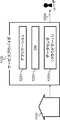
図1は、実施の形態1における話者識別システムを構成する話者識別装置200の構成例を示すブロック図である。図2は、図1に示される話者識別装置200の制御部205の機能を示すブロック図である。
FIG. 1 is a block diagram showing a configuration example of a
話者識別装置200は、図1に示されるように、音声取得部201、音声データベース(DB)203、表示部204、及び制御部205を備える。また、話者識別装置200は、通信部202、入力受付部206をさらに備えていてもよい。話者識別装置200の制御部205は、図2に示されるように、音声処理部101、データベース管理部102、識別処理部103、及び表示制御部104を含む。 As shown in FIG. 1, the
ここで、話者識別装置200は、例えば一般家庭用のテレビ、パーソナルコンピュータ(PC)におけるモニタなどでもよい。ここでは、話者識別装置200として、特に、上記の「本開示の基礎となった知見」にて説明した通り、話者識別結果を表示するためだけの専用表示装置というよりは、別のコンテンツ等を表示することのできる装置を想定している。ただし、表示機能を有する装置に上記の各構成が備えられていれば、いかなる装置を採用してもよい。 Here, the
また、各構成は、必ずしも、話者識別装置200の筐体の内部に配置されていなくてもよい。例えば音声取得部201が、話者識別装置200の筐体の外部に接続されていても、その音声取得部201は、話者識別装置200に含まれる。話者識別装置200は、一の家庭に一台のみ配置されているとは限らず、一の家庭に複数台配置されている場合もある。話者識別装置200は、この実施の形態1では、一般家庭用のテレビである。 Further, each configuration may not necessarily be disposed inside the housing of the
音声取得部201は、例えばマイクロフォンなどである。音声取得部201は、話者識別装置200を視聴している視聴者が発話した音声を取得する。ここで、音声取得部201には、指向性を制御する機器が備わっていてもよい。この場合には、視聴者の存在する方向に指向性を持たせることにより、視聴者が発話した音声を取得する精度を向上させることができる。また、話者が位置する方向を検出することができる。 The
また、音声取得部201は、人の発話に関する音声以外の音を、取得しない機能(もしくは除去する機能)を有していてもよい。この実施の形態1のように、例えば話者識別装置200がテレビの場合、音声取得部201は、取得した音声からテレビの音声信号を除去する機能を有していてもよい。これによって、視聴者が発話した音声を取得する精度を向上させることができる。 In addition, the
音声DB203は、情報を蓄積(記録)することが可能な記録媒体等で構成される。音声DB203は、話者識別装置200の筐体の内部に設けられていなくてもよい。音声DB203が例えば外付けの記録媒体等で構成されて、話者識別装置200の筐体の外部に接続されていても、音声DB203は、話者識別装置200に含まれる。 The
音声DB203には、話者識別装置200を保持している家族の音声、家族の動作音または家族の音声以外の音声、さらに家族の構成員(ユーザ)の年齢及び性別等の情報が蓄積されて管理されている。音声DB203に蓄積されている情報の詳細については特に限定しないが、音声取得部201が取得した話者識別装置200周辺の音声から、ユーザを特定できる情報が蓄積されていればよい。 The
この実施の形態1では、例えば、音声DB203には、登録音声信号(音声信号のスペクトル又は周波数等から生成された情報)と、ユーザ情報(年齢、性別又はニックネーム等の情報)とが、互いに対応付けられて蓄積されている。また、この実施の形態1では、音声DB203には、各ユーザに対応する話者画像が対応付けられて蓄積されている。 In the first embodiment, for example, in the
図3は、音声DB203に蓄積されている音声情報800の一例を示す図である。音声情報800は、互いに対応付けられた、登録音声信号801と、ユーザ情報802と、登録アイコン803(話者画像の一例)とを含む。 FIG. 3 is a diagram showing an example of the
図3では、登録音声信号801は、音声信号のスペクトル又は周波数等の情報を基に生成された予め設定された次元数の特徴ベクトルを表す信号である。登録音声信号801は、この実施の形態1では、「.wav」形式のファイルとして登録されている。なお、登録音声信号801は、「.wav」形式のファイルでなくてもよい。例えば、登録音声信号801は、MPEG−1 Audio Layer 3、Audio Interchange File Format等の音声圧縮されたデータで生成されてもよい。また、登録音声信号801は、例えば自動的に圧縮ファイルにエンコードされ、音声DB203に格納されてもよい。 In FIG. 3, the registered
ユーザ情報802は、ユーザ(話者)の属性を表す情報である。この実施の形態1では、図3に示されるように、ユーザ情報802は、ユーザの属性として、「年齢」、「性別」、「ニックネーム」を含む。図3のユーザ情報802の例では、登録音声信号801が「0001.wav」のユーザに対応付けて、「年齢」が「40代」に、「性別」が「男性」に、「ニックネーム」が「パパ」に、それぞれ設定されている。「年齢」及び「性別」については、データベース管理部102等が自動的に登録してもよく、ユーザが入力受付部206を用いて登録してもよい。「ニックネーム」については、ユーザが入力受付部206を用いて登録すればよい。 The
登録アイコン803は、ユーザ(話者)を表す話者画像である。図3の登録アイコン803の例では、登録音声信号801が「0001.wav」のユーザに対応付けて、「アイコンA01」が設定され、登録音声信号801が「0003.wav」のユーザに対応付けて、「アイコンB05」が設定されている。登録アイコン803は、後述の図8Aに示されるように、○、□、△のような記号のアイコンでもよい。あるいは、登録アイコン803は、後述の図8Bに示されるように、人の顔を模式的に表したアイコンでもよい。 The
登録アイコン803に関しては、制御部205は、予め作成された複数のアイコンのなかからユーザが選択したアイコン、またはユーザが自ら作成した画像を、登録アイコン803として音声情報800に登録してもよい。また、ユーザによってアイコンが音声情報800に登録されていない場合でも、制御部205が、ユーザ情報802を基に、ユーザ情報802に適合するアイコンを選択して、又は作成して、音声情報800に登録するようにしてもよい。 Regarding the
音声DB203に蓄積される音声情報800の構築方法についても特に限定しない。例えば予めユーザが初期登録することで音声情報800を構築できる。例えば、初期登録では、話者識別装置200の前にいるユーザが発話をするたびに、音声取得部201が音声を取得する。音声処理部101は、取得された話者の音声から特徴ベクトルを生成し、生成した特徴ベクトルを表す話者音声信号を生成する。データベース管理部102は、生成された話者音声信号を、登録音声信号801として自動的に音声DB203の音声情報800に登録する。このようにして、音声DB203が完成されてもよい。 There is no particular limitation on the method of constructing the
また、その初期登録の際に、入力受付部206は、ユーザが発話したタイミングでユーザ情報802を入力させるようなユーザインタフェースを表示部204に表示させてもよい。データベース管理部102は、ユーザの入力受付部206に対するユーザ情報802の入力内容を用いて、音声DB203の音声情報800を更新してもよい。 Further, at the time of the initial registration, the input receiving unit 206 may cause the
なお、音声情報800に関して、上述のように初期登録によって音声DB203に予め登録しておかなくても、ある程度の話者の情報を識別することもできる。一般的に、年齢差や性別によって、話者の音声の基本周波数が異なることが知られている。例えば、男性が発話する音声の基本周波数の平均は150Hz〜550Hz、女性が発話する音声の基本周波数の平均は400Hz〜700Hzと言われている。よって、初期登録に代えて、話者識別装置200の識別処理部103は、音声処理部101で生成された音声を表す信号の周波数などの情報を基に、ある程度の年齢及び性別を判断してもよい。データベース管理部102は、識別処理部103の判断結果に基づき、自動で音声DB203の音声情報800に、登録音声信号801及びユーザ情報802を登録するようにしてもよい。 In addition, regarding the
また、ユーザ情報802に関しては、図3に記載のものに限られない。制御部205は、各ユーザごとに視聴履歴の多い番組などの嗜好情報を、ユーザ情報802として音声DB203に蓄積するようにしてもよい。また、ユーザ情報802の取得方法に関しても限定しない。ユーザが、話者識別装置200を最初に使用するときに入力受付部206を用いてユーザ情報802の初期設定をするようにしてもよい。あるいは、最初に、ユーザの音声が取得されたタイミングで、ユーザが入力受付部206を用いてユーザ情報802を登録するようにしてもよい。 Further, the
図4は、音声DB203に蓄積される音声情報810の別の例を示す図である。図4に示される音声情報810は、互いに対応付けられた、登録音声信号801と音声データ804とを含む。音声データ804は、音声取得部201によって取得された話者の音声から、音声処理部101によって生成された発話内容を表すデータである。図4に示されるような音声情報810が、音声DB203に蓄積されていくようにしてもよい。 FIG. 4 is a diagram showing another example of the
この場合には、音声処理部101は、話者の音声の特徴ベクトルを表す話者音声信号に加えて、発話内容を表すデータを生成する。音声処理部101は、例えば音響モデル及び言語モデルを用いる音声認識技術によって、発話内容を表すデータを生成する。データベース管理部102は、音声処理部101によって生成された発話内容を表すデータを、音声DB203に音声データ804として蓄積する。 In this case, the
識別処理部103は、さらに、音声処理部101から出力された発話内容を表すデータと、音声DB203に蓄積されている音声データ804(発話内容)とを比較する。これによって、話者の特定精度を向上させることができる。 The
図4の例では、登録音声信号801が「0002.wav」のユーザが、あるタイミングで「料理番組を見ながら夕食を作りましょう」と発話していたことが記録されている。これにより、登録音声信号801が「0002.wav」に対応する話者が、別のタイミングで例えば「料理番組」等の同様の単語を発話した場合には、登録音声信号801が「0002.wav」に対応する話者の発話である可能性が高いと、識別処理部103が判断できる。 In the example of FIG. 4, it is recorded that the user of the
図1に戻って、表示部204は、一般的なモニタなどであり、特に限定しない。この実施の形態1では、表示部204は、テレビの表示画面である。表示部204は、制御部205の表示制御部104により制御されて、画像または情報を表示する。本実施の形態1の話者識別システムでは、表示部204は、取得された話者の音声に対応付けられた登録アイコン803を表示する。これにより、ユーザは、話者識別表示システムにより、誰が、または複数の人数が識別されているのかが明確に分かるようになる。 Returning to FIG. 1, the
また、後述の実施の形態2の話者識別システムでは、話者識別装置200の周辺に複数のユーザが存在する場合などに、話者識別が誤っていたことにより異なる登録アイコン803が表示された際には、簡易に修正が可能な構成にしている。表示部204に表示される登録アイコン803等の具体例は、図8A〜8Fを参照して後述する。 Further, in the speaker identification system according to the second embodiment described later,
制御部205は、例えばCPU又はマイクロコンピュータ、及びメモリなどを含む。制御部205は、音声取得部201、音声DB203、及び表示部204などの各構成の動作を制御する。例えばメモリに格納されたプログラムにしたがってCPU又はマイクロコンピュータが動作することにより、制御部205は、図2に示される音声処理部101、データベース管理部102、識別処理部103、及び表示制御部104として機能する。図2に示される制御部205の各機能は、図5を参照して後述される。 The
ここで、上記したように、話者識別装置200は通信部202を備えていてもよい。通信部202は、インターネット等と接続することで他の機器やサーバ装置と通信し、情報のやりとりを行う。 Here, as described above, the
また、話者識別装置200は、入力受付部206を備えていてもよい。入力受付部206は、ユーザからの入力を受け付ける。ユーザからの入力を受け付ける方法としては特に限定しない。入力受付部206をテレビのリモートコントローラで構成してもよい。あるいは、入力受付部206は、表示部204に操作のためのユーザインタフェースを表示してもよい。ユーザは、それらの入力受付部206によって、情報又は指示を入力することができる。 Further, the
図5は、本実施の形態1の話者識別システムの図1に示される話者識別装置200における処理を示すフローチャートである。 FIG. 5 is a flowchart showing processing in the
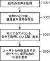
まず、ステップS301では、音声取得部201は、話者の発した音声を取得する。音声処理部101は、取得された話者の音声から、予め設定された次元数の特徴ベクトルを生成し、生成した特徴ベクトルを表す話者音声信号を生成する。 First, in step S301, the
続いて、ステップS302では、データベース管理部102は、音声DB203に蓄積されている音声情報800(図3)から、登録音声信号801を抽出して、識別処理部103に出力する。識別処理部103は、音声処理部101により生成された話者音声信号と、データベース管理部102から出力された登録音声信号801とを比較し、話者音声信号に対応する登録音声信号801を特定する。 Subsequently, in step S302, the
識別処理部103は、例えば話者音声信号と、音声DB203に蓄積されている各登録音声信号801との類似度をそれぞれ算出する。識別処理部103は、算出した類似度のうちで、最も高い類似度を抽出する。識別処理部103は、この最も高い類似度が予め設定された閾値以上のときに、その最も高い類似度に対応する登録音声信号801を、話者音声信号に対応すると判断する。具体的には例えば、識別処理部103は、話者音声信号の特徴ベクトルと登録音声信号801の特徴ベクトルとの距離をそれぞれ算出する。識別処理部103は、算出した距離が最も短い登録音声信号801と話者音声信号との類似度が最も高いと判断する。 The
続いて、ステップS303では、識別処理部103は、特定した登録音声信号801をデータベース管理部102に出力する。データベース管理部102は、音声DB203に蓄積されている音声情報800(図3)を参照して、出力された登録音声信号801に対応付けられている登録アイコン803を抽出する。データベース管理部102は、抽出した登録アイコン803を識別処理部103に出力する。 Subsequently, in step S303, the
識別処理部103は、出力された登録アイコン803を表示制御部104に出力する。音声処理部101は、音声取得部201により話者の音声が取得されている間だけ、その旨を表す取得信号を、話者ごとに表示制御部104に出力する。 The
表示制御部104は、識別処理部103から出力された登録アイコン803を、音声処理部101から取得信号が入力されている間、表示部204に表示する。表示制御部104は、音声取得部201が取得している話者の音声から、特定された話者を示す音声が所定時間途絶えたとき、つまり音声処理部101から特定された話者の取得信号が入力されなくなった時点から所定時間(この実施の形態1では、例えば10秒)が経過したときに、表示制御部104は、表示部204に表示されているアイコンを消去する。この場合、表示制御部104は、表示されているアイコンの透明度を徐々に増大させて、アイコンを表示部204からフェードアウトさせるようにしてもよい。 The
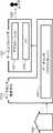
図6は、本実施の形態1における話者識別システムの別の構成例を示すブロック図である。図6では、図1と同一要素については同一符号が付されている。以下、図1の話者識別システムとの相違点を中心に、図6の話者識別システムが説明される。 FIG. 6 is a block diagram showing another configuration example of the speaker identification system in the first embodiment. In FIG. 6, the same elements as in FIG. 1 are denoted by the same reference numerals. Hereinafter, the speaker identification system of FIG. 6 will be described focusing on differences from the speaker identification system of FIG.
図6の話者識別システムは、話者識別装置200と、サーバ装置210とを備える。図6の話者識別システムでは、音声DB203は、図1の話者識別システムと異なり、サーバ装置210に含まれている。すなわち、話者識別装置200は、音声取得部201、通信部202、表示部204、及び制御部205を備え、音声DBを備えない。図6の話者識別システムでも、話者識別装置200は、上記したように、一般家庭用のテレビ、またはパーソナルコンピュータ(PC)におけるモニタなどでもよい。図1と同様に、話者識別装置200は、一般家庭用のテレビである。 The speaker identification system of FIG. 6 includes a
また、サーバ装置210は、制御部211、通信部212、及び音声DB203を備える。サーバ装置210が置かれている場所に関しては、特に限定しない。ビッグデータを取り扱うデータセンターを管理又は運営する会社が保有するデータセンターに配置されていてもよく、各家庭に配置されていてもよい。 The
話者識別装置200の通信部202は、インターネットなどのネットワーク220を介して、サーバ装置210の通信部212と通信する。これにより、話者識別装置200の制御部205は、例えば生成した話者音声信号を、通信部202を介してサーバ装置210に送信することができる。サーバ装置210は、通信部212を介して、複数の話者識別装置200と接続されていてもよい。 The
図6の話者識別システムでは、図2に示される各機能は、サーバ装置210の制御部211と、話者識別装置200の制御部205との、いずれかに含まれていればよい。例えば音声処理部101は、音声取得部201が取得した話者の音声を処理するため、話者識別装置200の制御部205に含まれていてもよい。例えばデータベース管理部102は、音声DB203を管理するため、サーバ装置210の制御部211に含まれていてもよい。例えば表示制御部104は、表示部204を制御するため、話者識別装置200の制御部205に含まれていてもよい。 In the speaker identification system of FIG. 6, each function shown in FIG. 2 may be included in any of the
音声DB203は、サーバ装置210が複数の話者識別装置200と接続されている場合には、複数の話者識別装置200の各々に対応する音声情報800(図3)をそれぞれ保存して管理してもよい。 The
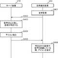
図7は、図6の話者識別システムにおける動作の一例を示すシーケンス図である。なお、図7では、図2に示される各機能のうち、データベース管理部102及び識別処理部103は、サーバ装置210の制御部211に含まれ、音声処理部101及び表示制御部104は、話者識別装置200の制御部205に含まれている。また、ここでは、図6に示したサーバ装置210と話者識別装置200とを含む話者識別システムの動作の例を示すが、あくまで一例であり、本実施の形態を限定するものではない。 FIG. 7 is a sequence diagram showing an example of the operation in the speaker identification system of FIG. In FIG. 7, among the functions shown in FIG. 2, the
まず、ステップS401にて、話者識別装置200における音声取得部201が、話者の音声を取得する。音声処理部101は、取得された話者の音声から特徴量を抽出し、抽出した特徴量を表す話者音声信号を生成する。本ステップS401は、図5に示すステップS301に相当する。 First, in step S401, the
ステップS401において、音声取得部201により取得された話者の音声に対して音声処理部101が特徴量抽出などの処理を行うタイミングに関しては限定しない。話者識別装置200であるテレビの電源がONになっている間、常に、音声取得部201が音声を取得して、音声処理部101が特徴量抽出などの処理を行ってもよい。また、音声処理部101がマジックワード(所定の単語)を検出した時に、その検出時点以降に音声取得部201が取得した音声に対して音声処理部101が特徴量抽出などの処理を開始してもよい。また、人が発声した音声と、話者の音声以外の環境音とを音声処理部101が識別して、人が発声した音声のみに対して、音声処理部101が特徴量抽出などの処理を行うようにしてもよい。 There is no limitation on the timing at which the
続いて、ステップS402にて、話者識別装置200における通信部202は、ネットワーク220を介して、音声処理部101により生成された話者音声信号をサーバ装置210に送信する。この時、一つのサーバ装置210に対して複数の話者識別装置200が接続されている場合、話者音声信号とともに、話者識別装置200を特定する識別情報を送信するようにしてもよい。 Subsequently, in step S402, the
続いて、ステップS403にて、サーバ装置210の制御部211の識別処理部103は、データベース管理部102を介して、音声DB203に蓄積されている登録音声信号801を取得する。そして、識別処理部103は、取得した登録音声信号801と、ステップS402にて通信部212を介して話者識別装置200から取得した話者音声信号とを比較して、話者音声信号と一致する登録音声信号801(話者)を特定する。本ステップS403は、図5に示すステップS302に相当する。 Subsequently, in step S403, the
続いて、ステップS404にて、制御部211の識別処理部103は、データベース管理部102を介して、特定された登録音声信号801に対応する登録アイコン803を抽出する。例えば図3において、登録音声信号801が「0001.wav」及び「0003.wav」の話者に対しては、それぞれアイコンA01、B05が登録アイコン803として登録されている。そこで、これらの話者については、識別処理部103は、各々の登録アイコン803を抽出すればよい。 Subsequently, in step S404, the
また、図3の例では、登録音声信号801が「0002.wav」の話者には登録アイコン803が登録されていない。この場合は、制御部211の識別処理部103は、予め作成された複数のアイコンから自動的に抽出してもよい。また、話者識別装置200から取得した話者音声信号が、登録音声信号801のいずれとも対応しない場合にも、同様に、制御部211の識別処理部103は、取得した話者音声信号から類推される適切なアイコンを予め作成された複数のアイコンから抽出してもよい。あるいは、識別処理部103は、話者識別装置200から取得した話者音声信号に対応する登録アイコン803が音声情報800に登録されていない場合には、話者音声信号から類推される適切なアイコンを作成してもよい。この点については、図1に示される構成の話者識別システムの場合でも同様である。 Further, in the example of FIG. 3, the
続いて、ステップS405にて、サーバ装置210の通信部212は、ネットワーク220を介して、ステップS404にて識別処理部103により抽出されたアイコンを話者識別装置200へ送信する。 Subsequently, in step S405, the
続いて、ステップS406にて、話者識別装置200の制御部205の表示制御部104は、ステップS405にて送信されたアイコンを表示部204に表示させる。本ステップS406は、図5に示すステップS303に相当する。 Subsequently, in step S406, the
このとき、上述のように、音声処理部101は、音声取得部201により話者の音声が取得されている間だけ、その旨を表す取得信号を、話者ごとに表示制御部104に出力する。表示制御部104は、音声処理部101から取得信号が入力されている間、つまり特定された話者の音声を認識している間、アイコンを表示部204に表示させる。 At this time, as described above, only while the
表示制御部104は、音声取得部201が取得している話者の音声から、特定された話者を示す音声が所定時間途絶えたとき、つまり音声処理部101から取得信号が入力されなくなった時点から所定時間(この実施の形態1では、例えば10秒)が経過したときに、表示制御部104は、表示部204に表示されているアイコンを消去する。この場合、表示制御部104は、表示されているアイコンの透明度を徐々に増大させて、アイコンを表示部204からフェードアウトさせるようにしてもよい。 The
図8A〜8Hは、それぞれ、図1又は図6に示される話者識別システムにおいて、表示制御部104によって表示部204に表示される登録アイコン803の具体的な表示例を示す図である。なお、あくまで、図8A〜8Hに記載の表示構成は一例であり、図8A〜8Hに示されている表示構成以外の表示構成を備えていてもよく、また一部の表示構成が欠けていてもよい。 8A to 8H are diagrams showing specific display examples of the
図8Aでは、ステップS403にて特定された話者に対応する記号をアイコンとして、それぞれ色分けして話者識別装置200の表示部204の右下隅に表示している。図8Aの例では、アイコン911は丸の記号であり、アイコン912は四角の記号であり、アイコン913は三角の記号である。上記したように、ステップS406にて、表示制御部104は、これらの記号で表示されたアイコンを、話者が発話している間及びその後の所定時間だけ表示部204に表示する。このように表示することで、ユーザは、テレビ放送の表示が過度に邪魔されることなく、話者識別の結果を確認できる。 In FIG. 8A, the symbol corresponding to the speaker identified in step S403 is displayed as an icon in the lower right corner of the
ここで、図8Aにて表示されているタイミングでは、アイコン911、アイコン912、アイコン913の3人の話者が同時に発話していることになる。例えば、あるタイミングで、アイコン912に対応する話者の発話が止まった時点から所定時間(この実施の形態1では、例えば10秒)が経過すると、表示制御部104は、アイコン912だけを消去する。その結果、表示部204には、アイコン911及びアイコン913のみが表示されている状態になる。 Here, at the timing displayed in FIG. 8A, three speakers of an
その際、表示制御部104は、アイコン911が表示される位置を右にスライドさせ、アイコン911をアイコン913の直ぐ隣に表示するようにしてもよい。これにより、常に表示部204の右下隅にアイコンが集まることになり、テレビ放送の表示が過度に妨げられるのを抑制できる。 At this time, the
なお、発話が止まった際に、表示制御部104は、アイコンを消去するのに代えて、アイコンの色を半透明にしてもよい。あるいは、発話が止まった際に、表示制御部104は、アイコンの大きさを小さく変化させてもよい。これらによっても、同様の効果が得られる。 In addition, when the speech stops, the
また、認識された話者に対応する複数のアイコンを一定時間表示するようにして、右もしくは左から複数の話者が発声した順に並べて表示してもよい。図8Aの例では、アイコン911,912,913の順で、もしくはアイコン913,912,911の順で、対応する話者が発声していることが示される。もちろん、上もしくは下から順に表示してもよい。これにより、発話のたびにアイコンの表示の順序が入れ替わる。したがって、ユーザへ発話を促すことができる。 Further, a plurality of icons corresponding to the recognized speakers may be displayed for a predetermined time, and may be displayed side by side in the order in which the plurality of speakers uttered from the right or the left. In the example of FIG. 8A, it is shown that the corresponding speaker utters in the order of the
また、図8Aに示されるように、表示制御部104は、認識されている話者のうち、発話をしている話者を示すアイコンに対して、発話をしている間だけ、補足アイコン914を表示してもよい。図8Aの例では、補足アイコン914として、発話中の話者を示すアイコンを丸の形状で囲むアイコンが採用されており、現在、アイコン911に対応する話者が発話をしていることが示されている。 In addition, as shown in FIG. 8A, the
この場合、表示制御部104は、音声処理部101から話者ごとに出力される取得信号に基づき、補足アイコン914を表示する対象のアイコンを決定する。これにより、話者識別装置200の付近にいることが認識されている話者を示すアイコン912,913と、現在発話をしている話者を示すアイコン911とを、明確に区別して表示できる。 In this case, the
図8Bに示されるように、表示制御部104は、表示部204に表示するアイコンを、図8Aのような記号ではなくて、人の形を概略的に表したアイコン915〜918としてもよい。上記したように、このアイコン915〜918を、ユーザが選択してもよく、ユーザが作成してもよく、サーバ装置210の制御部211もしくは話者識別装置200の制御部205が選択するようにしてもよい。この場合でも、図8Aと同様に、表示制御部104は、補足アイコン914を表示部204に表示してもよい。 As shown in FIG. 8B, the
また、表示制御部104は、アイコン付近またはアイコンの上に話者が発話した内容を都度表示するようにしてもよい。この場合には、表示制御部104は、アイコンを例えば半透明にして常に表示しておき、発話内容を話者が発話している間だけ表示するようにしてもよい。 Further, the
なお、図8Bでは、音声取得部201または音声処理部101は、指向性を制御する機能を有している。これにより、制御部205は、表示部204の前に位置する話者の存在する方向に指向性を持たせ、話者が位置する方向を検出することができる。そこで、表示制御部104は、図8Bに示されるように、検出した発話者の位置する方向に合わせてアイコンを表示させる位置を変化させてもよい。図8Bの例では、アイコン915,916に対応する話者は、表示部204の中心線から左側に位置し、アイコン917,918に対応する話者は、表示部204の中心線から右側に位置することが分かる。このように表示することで、ユーザは、話者識別の結果を確認しやすくなる。 In FIG. 8B, the
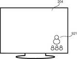
図8Cに示されるように、複数の話者が一斉に発声した場合に、表示制御部104は、音声DB203に新規に登録された話者に対して、仮で設定したアイコン921を大きく表示してもよい。 As shown in FIG. 8C, when a plurality of speakers speak at the same time, the
ここで、「新規に登録」は以下のように行われる。この話者が発話した時点では、この話者の登録音声信号801は、音声情報800に登録されていない。そこで、識別処理部103は、音声処理部101により生成された話者音声信号を、データベース管理部102を介して、登録音声信号801として、音声情報800に登録する。識別処理部103は、話者音声信号から話者の属性を判断する。識別処理部103は、その判断結果に基づき、アイコンを仮に設定して、データベース管理部102を介して、音声情報800に登録アイコン803として登録する。このようにして、未登録の話者は、音声DB203に新規に登録される。 Here, “newly registered” is performed as follows. When the speaker speaks, the registered
これにより、ユーザは、新規の話者を確認することができる。また、新規の話者に対して、アイコンの選択または作成によって、仮に設定されたアイコンを好みのアイコンに変更するのを促すことができる。 This allows the user to confirm a new speaker. Also, it is possible to prompt the new speaker to change the temporarily set icon to a favorite icon by selecting or creating the icon.
図8Dに示されるように、複数の話者が発話した場合に、表示制御部104は、発話時間または発話回数が最も多い話者に対応するアイコンを、大きく表示してもよい。この場合には、識別処理部103は、話者ごとに発話時間または発話回数をカウントし、データベース管理部102を介して、カウント値を音声DB203に蓄積する。表示制御部104は、データベース管理部102を介して、蓄積されたカウント値を音声DB203から取得する。 As shown in FIG. 8D, when a plurality of speakers speak, the
図8Dの例では、アイコン922に対応する話者の発話時間または発話回数が最も多いことが分かる。これにより、話者の発話を促すことができる。話者の発話を促すことで、音声DB203に蓄積される音声情報800の量を増加することができる。その結果、より精度の高い話者認識が可能となる。 In the example of FIG. 8D, it can be seen that the speaker's utterance time or number of utterances corresponding to the
図8Dのようにアイコン922を拡大表示するだけではなくて、表示制御部104は、図8Eに示されるように、発話量表示部931,932を表示部204に表示してもよい。発話量表示部931,932は、発話時間または発話回数に基づく発話量をバーで表示したものである。発話量は、発話時間が長くなると、または発話回数が多くなると、増大する。 The
発話量表示部931は、例えば話者識別装置200を所有する家族単位での発話量を表す。発話量表示部932は、例えばサーバ装置210に接続されている全ての話者識別装置200における発話量の平均値を表す。なお、発話量表示部932は、サーバ装置210に接続されている全ての話者識別装置200のうちで、同一のテレビ放送番組が視聴されている話者識別装置200における発話量の平均値を表すようにしてもよい、
図8Eの場合には、例えば、発話量表示部931のレベルが発話量表示部932のレベルに比べて低い場合には、話者の発話が促されることとなる。また、サーバ装置210の制御部211は、発話量表示部931のレベルによって、現在視聴しているテレビ放送番組またはコマーシャルをユーザが熱心に視聴しているか否かのデータを収集することができる。The amount-of-
In the case of FIG. 8E, for example, when the level of the utterance
なお、図1の話者識別システムの場合には、表示制御部104は、発話量表示部931の表示のみを行うことができる。表示制御部104による発話量表示部932の表示は、図6の話者識別システムによって実現される。 In the case of the speaker identification system of FIG. 1, the
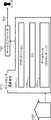
図8Fに示されるように、表示制御部104は、アイコン911〜914を表示部204に表示する際に、テレビ放送番組を表示するメイン表示領域941を表示部204の表示画面全体から縮小してもよい。表示制御部104は、メイン表示領域941の外側に、サブ表示領域942を設けて、このサブ表示領域942にアイコン911〜914を表示してもよい。これによって、アイコン911〜914の表示によりテレビ放送番組の視聴が過度に妨げられる事態を抑制することができる。 As shown in FIG. 8F, when displaying the
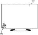
図8A〜8Fでは、複数のアイコンが表示部204に表示されているが、図8G,8Hに示されるように、1個のアイコンが表示部204に表示される場合もある。例えば図8Aにおいて、アイコン913に対応する話者のみが発話を続け、アイコン911,912に対応する話者の発話が停止した場合、その停止時点から所定時間(この実施の形態1では、例えば10秒)が経過すると、表示制御部104は、図8Gに示されるように、アイコン913のみを表示部204に表示し、他のアイコンを消去する。 In FIGS. 8A to 8F, although a plurality of icons are displayed on the
例えば図8Bにおいて、アイコン915に対応する話者のみが発話を続け、アイコン916〜918に対応する話者の発話が停止した場合、その停止時点から所定時間(この実施の形態1では、例えば10秒)が経過すると、表示制御部104は、図8Hに示されるように、アイコン915のみを表示部204に表示し、他のアイコンを消去する。 For example, in FIG. 8B, when only the speaker corresponding to the
以上説明されたように、本実施の形態1における話者識別システムによれば、表示部204が本来表示したいコンテンツ(例えば表示部204がテレビの表示画面であれば、テレビ放送番組)の表示の妨げになることを抑制しつつも、ユーザへ話者の識別結果を明確に表示することができる。 As described above, according to the speaker identification system in the first embodiment, it is possible to display the content that the
なお、あくまで、図1、図6に記載の構成は、本実施の形態1の話者識別システムの一例であり、図1、図6に示されている構成以外の構成を備えていてもよく、また一部の構成が欠けていてもよい。また、図1、図6のいずれを採用してもよいし、図示した以外の装置を本実施の形態1の話者識別システムに採用することもできる。 The configurations shown in FIGS. 1 and 6 are merely examples of the speaker identification system according to the first embodiment, and may have configurations other than the configurations shown in FIGS. 1 and 6. Also, some configurations may be missing. Further, either of FIG. 1 and FIG. 6 may be adopted, and apparatuses other than those shown in the drawings can be adopted in the speaker identification system of the first embodiment.
(実施の形態2)
以下、実施の形態2における話者識別システムを説明する。なお、本実施の形態2では一部、実施の形態1と同様の説明は省略している。また、実施の形態2の技術を実施の形態1に記載の技術と組み合わせることも可能である。Second Embodiment
The speaker identification system in the second embodiment will be described below. In the second embodiment, a part of the description similar to that of the first embodiment is omitted. Further, it is also possible to combine the technology of the second embodiment with the technology described in the first embodiment.
本実施の形態2における話者識別システムの構成は、図1または図6に示される実施の形態1の話者識別システムと同様であるので、詳細な説明を省略する。実施の形態2では、実施の形態1と同一構成については、同じ符号を用いて説明する。ただし、本実施の形態2においては、図1または図6に示される入力受付部206が必須の構成となる。 The configuration of the speaker identification system according to the second embodiment is the same as that of the speaker identification system according to the first embodiment shown in FIG. 1 or FIG. In the second embodiment, the same components as those of the first embodiment will be described using the same reference numerals. However, in the second embodiment, the input receiving unit 206 shown in FIG. 1 or 6 is an essential component.
図9は、実施の形態2における、図1に示される話者識別装置200の制御部205の機能を示すブロック図である。図2に示される実施の形態1と異なるのは、修正制御部105を備えていることである。この修正制御部105により、識別処理部103が抽出したアイコンが誤っている場合に、ユーザが修正を行い、音声DB203の情報を更新することが可能となる。このような構成により、実施の形態2では、識別処理部103により識別された情報を修正することが簡易に行えるようになる。修正制御部105の具体的な動作については、図10を参照して、次に説明する。 FIG. 9 is a block diagram showing the function of
図10は、実施の形態2の話者識別システムの図1に示される話者識別装置200における処理を示すフローチャートである。ステップS301〜S303は、図5のステップS301〜S303と同様である。 FIG. 10 is a flow chart showing processing in the
ステップS303に続いて、ステップS304では、修正制御部105は、話者に対応するアイコンについて、ユーザからの修正指示を受け付ける。ユーザは、入力受付部206を用いて、修正指示を行う。修正制御部105は、ユーザの修正指示の内容にしたがって、データベース管理部102を介して、音声DB203の内容を更新する。 Following step S303, in step S304, the
ここで、ステップS304にて、修正制御部105は、ステップS303にてアイコンが表示されている間のみ、ユーザからの修正指示を受け付けるよう制御してもよい。これにより、修正を意図していないタイミングで誤って修正指示を受け付けてしまうことを低減できる。また、この場合、修正制御部105は、表示制御部104を通じて、アイコンが表示されている間に、ユーザからの修正指示を受け付けることが可能である旨の表示を表示部204に表示させてもよい。これにより、ユーザは修正機能があることを把握できる。 Here, in step S304, the
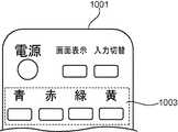
図11A,11Bは、図10のステップS304における修正指示にユーザが用いる入力受付部206の一例を示す図である。図11A,11Bを参照して、図10のステップS304において、ユーザが入力受付部206を用いて、アイコンについての修正指示を行う方法が説明される。図11Aは、入力受付部206の一例であるリモートコントローラ(以下、「リモコン」という)1001を示す。図11Bは、入力受付部206の別の例であるリモコン1002を示す。 11A and 11B illustrate an example of the input reception unit 206 used by the user for the correction instruction in step S304 in FIG. With reference to FIGS. 11A and 11B, a method will be described in which the user uses the input receiving unit 206 in step S304 of FIG. FIG. 11A illustrates a remote controller (hereinafter, referred to as “remote control”) 1001 which is an example of the input reception unit 206. FIG. 11B shows a
図10のステップS303において、アイコンが誤って表示部204に表示された場合、ユーザは、例えばリモコン1001を使用して修正指示を送る(図10のステップS304)。アイコンが誤って表示部204に表示された場合とは、例えば、図8Bに示すような表示例では、アイコン915に対応する話者の発話中に、補足アイコン914が、誤って図8Bのように別の話者を示すアイコン916上に表示されていることなどである。 If the icon is erroneously displayed on the
ここで、図11Aのリモコン1001において、カラーボタン1003の各ボタンは、予め各アイコンと対応付けられている。例えば図8Bにおいて、アイコン915は「青」ボタンと、アイコン916は「赤」ボタンと、アイコン917は「緑」ボタンと、アイコン918は「黄」ボタンと、それぞれ対応付けられているとする。この場合において、各アイコン915〜918には、それぞれ対応付けられている色が、ユーザに分かるように重畳されて表示されていることが望ましい。 Here, in the
なお、あらかじめ話者とリモコンのカラーボタン1003の各ボタンとを対応付けておかなくてもよい。例えば、カラーボタン1003のうち任意のカラーボタンを押して修正することでもよい。また、アイコンが表示されている位置における左から順に、「青」、「赤」、「緑」、「黄」のボタンが対応付けられてもよい。 The speaker may not be associated with each button of the
図10のステップS304における修正指示として、アイコン915に対応する話者が、リモコン1001の「青」ボタンを押しながら発話する。すると補足アイコン914がアイコン915上に移動し、登録されているアイコンに対して正しい話者画像を表示することができる。これにより、誤って識別結果が表示された場合であっても、話者に対応付けられたリモコン1001のカラーボタン1003を選択し、修正指示を送ることで簡易に修正可能となる。 As a correction instruction in step S304 in FIG. 10, the speaker corresponding to the
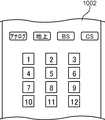
また、図11Aに示されるリモコン1001に代えて、図11Bに示されるリモコン1002を用いてもよい。図11Bに示されるリモコン1002では、同様に、各アイコンと、リモコン1002の数字ボタンとが対応付けられていればよい。この場合には、ユーザは、リモコン1002の対応する数字ボタンを押しながら発話をすることで、修正指示を送ることができる。 Also, in place of the
なお、ユーザが修正指示を送る方法は、上記に限られない。例えば、対応するリモコンのボタンを押したときに、表示制御部104は、修正可能な設定ページに表示部204の表示を切り替えるようにしてもよい。 Note that the method for the user to send a correction instruction is not limited to the above. For example, when the button of the corresponding remote control is pressed, the
図10に戻って、ステップS304で行われる音声DB203の内容の更新が説明される。アイコン915に対応する話者の発話中に、補足アイコン914が、誤って図8Bのように別の話者を示すアイコン916上に表示された原因は、アイコン915に対応する話者の登録音声信号801(図3)が、特徴ベクトルを正確に表していないことにある可能性が高い。 Referring back to FIG. 10, the update of the content of the
そこで、アイコン915に対応する話者が、リモコン1001の「青」ボタンを押しながら発話すると、音声処理部101は、音声取得部201により取得された音声から特徴ベクトルを生成し、生成した特徴ベクトルを表す話者音声信号を生成する。データベース管理部102は、識別処理部103を介して生成された話者音声信号を受け取り、音声DB203のアイコン915に対応する話者の登録音声信号801を、生成された話者音声信号に書き換える。 Therefore, when the speaker corresponding to the
ステップS304で行われる音声DB203の内容の更新の別の例が、図3、図8B及び図8Hを参照して説明される。 Another example of the update of the content of the
リモコン1001のカラーボタン1003が、図3の3人の話者に対応付けられている。例えば、登録音声信号801が「0001.wav」の話者は「青」ボタンに対応付けられ、登録音声信号801が「0002.wav」の話者は「赤」ボタンに対応付けられ、登録音声信号801が「0003.wav」の話者は「緑」ボタンに対応付けられている。また、図3の登録アイコン「A01」は、図8Bのアイコン916である。また、図3の登録アイコン「B05」は、図8B,8Hのアイコン915である。 The
この場合において、登録音声信号801が「0001.wav」の話者が発話中であるのに、図8Hに示されるように、アイコン915が表示部204に表示される。この原因は、図3の登録音声信号「0001.wav」が、特徴ベクトルを正確に表していないことにある可能性が高い。 In this case, the
そこで、登録音声信号801が「0001.wav」の話者(つまりアイコン916に対応する話者)が、リモコン1001の「青」ボタンを押しながら発話する。音声処理部101は、音声取得部201により取得された音声から特徴ベクトルを生成し、生成した特徴ベクトルを表す話者音声信号を生成する。データベース管理部102は、識別処理部103を介して生成された話者音声信号を受け取り、音声DB203の登録音声信号「0001.wav」を、生成された話者音声信号に書き換える。 Therefore, a speaker whose registered
図12は、実施の形態2の図6に示される話者識別システムにおける動作の一例を示すシーケンス図である。なお、図12では、図9に示される各機能のうち、データベース管理部102及び識別処理部103は、サーバ装置210の制御部211に含まれ、音声処理部101、表示制御部104、及び修正制御部105は、話者識別装置200の制御部205に含まれている。また、ここでは、図6に示したサーバ装置210と話者識別装置200とを含む話者識別システムの動作の例を示すが、あくまで一例であり、本実施の形態を限定するものではない。 FIG. 12 is a sequence diagram showing an example of the operation in the speaker identification system shown in FIG. 6 of the second embodiment. In FIG. 12, among the functions shown in FIG. 9, the
ステップS401〜S406は、図7に示すステップS401〜S406と同様なので、詳細な説明を省略する。 Steps S401 to S406 are similar to steps S401 to S406 shown in FIG. 7, and thus detailed description will be omitted.
ステップS406に続いて、ステップS407にて、修正制御部105は、入力受付部206を用いて行われるアイコンについてのユーザからの修正指示を、受け付ける。本ステップS407は、図10に示すステップS304の一部に相当する。すなわち、ユーザによる修正指示は、図10のステップS304と同様に行われる。 Subsequent to step S406, in step S407, the
ステップS407に続いて、ステップS408にて、話者識別装置200の通信部202は、修正制御部105が受け付けたユーザからの修正指示を、サーバ装置210へ送信する。 Following step S407, in step S408, the
続いて、ステップS409において、サーバ装置210のデータベース管理部102は、ユーザの修正指示に基づき、音声DB203の内容を更新する。本ステップS409は、図10に示すステップS304の一部に相当する。すなわち、音声DB203の更新は、図10のステップS304と同様に行われる。 Subsequently, in step S409, the
以上説明されたように、本実施の形態2の話者識別システムによれば、話者の識別結果として表示部204に表示されたアイコンが、誤った識別により異なるアイコンであった際にも、ユーザが煩わしい操作をすることなく、修正を指示することができる。もし、話者識別の結果に誤検出があり、その結果がそのまま表示されていると、ユーザにとって不快感が生じると考えられる。しかし、本実施の形態2では、そのようなユーザの不快感を解消できる。さらに、ユーザによる音声DB203の修正を促進することにもなる。したがって、より高精度で、家族の音声DB203を構築することができる。 As described above, according to the speaker identification system of the second embodiment, even when the icons displayed on the
(その他)
(1)上記実施の形態2において、図9の修正制御部105は、ユーザによる入力受付部206を用いた修正指示を、誤ったアイコンが表示部204に表示されている間のみ、受け付けるようにしてもよい。例えば図10のステップS304において図8Bを用いて説明した例では、補足アイコン914が誤って表示部204に表示されている間のみ、修正制御部105は、ユーザによるリモコン1001を用いた修正指示を受け付ける。例えば図10のステップS304において図3を用いて説明した例では、アイコン「B05」が誤って表示部204に表示されている間のみ、修正制御部105は、ユーザによるリモコン1001を用いた修正指示を受け付ける。(Others)
(1) In the second embodiment, the
この場合、表示制御部104は、表示部204に表示中のアイコンに関する情報を、修正制御部105に出力するようにしてもよい。修正制御部105は、表示制御部104から入力される、表示部204に表示中のアイコンに関する情報に基づき、ユーザによる入力受付部206を用いた修正指示が、表示部204に表示中のアイコンの修正指示であるか否かを判断してもよい。修正制御部105は、ユーザによる入力受付部206を用いた修正指示が、表示部204に表示中のアイコンの修正指示である場合にのみ、修正指示を受け付けるようにしてもよい。 In this case, the
このように、ユーザによる入力受付部206を用いた修正指示の受付可能な期間を限定することによって、表示部204に表示されていないアイコンに関する修正指示、又はユーザによる誤った修正指示を受け付けるような事態を避けることができる。 As described above, by limiting the period during which the user can accept a correction instruction using the input reception unit 206, the user can receive a correction instruction regarding an icon not displayed on the
(2)上記実施の形態1,2では、図8A〜図8Fに示されるように、アイコンを表示する表示部204は、話者識別装置200であるテレビの表示画面としている。しかし、本開示は、これに限られない。例えば、表示部204は、タブレット端末又はいわゆるスマートフォンなどの携帯装置の表示画面としてもよい。表示制御部104は、通信部202を介して、携帯装置の表示画面にアイコンを表示してもよい。 (2) In the first and second embodiments, as shown in FIGS. 8A to 8F, the
(3)上記実施の形態1,2において、連続して音声処理部101から入力される2つの話者音声信号が、図3の音声情報800の登録音声信号801が「0001.wav」及び「0003.wav」の話者に一致すると識別処理部103が判断すると、識別処理部103は、図3のユーザ情報802に基づき、父親と子供が一緒にテレビ放送番組を視聴していると判断できる。 (3) In the first and second embodiments, the two speaker voice signals inputted from the
あるいは、連続して音声処理部101から入力される2つの話者音声信号が、図3の音声情報800の登録音声信号801が「0001.wav」及び「0002.wav」の話者に一致すると識別処理部103が判断すると、識別処理部103は、図3のユーザ情報802に基づき、大人のみがテレビ放送番組を視聴していると判断できる。 Alternatively, when two speaker voice signals input from the
そこで、表示制御部104は、表示部204を用いて、識別処理部103による視聴者の判断結果に基づき、視聴者に適合するコンテンツ(例えばテレビ放送番組)を、視聴者に対して推奨するようにしてもよい。 Therefore, the
(提供するサービスの全体像)
図13Aは、上記実施の形態1,2における図6に示される話者識別システムの全体像を示す図である。(Overview of services provided)
FIG. 13A is a diagram showing an overview of the speaker identification system shown in FIG. 6 in the first and second embodiments.
グループ1100は、例えば企業、団体、家庭等であり、その規模を問わない。グループ1100には、複数の機器1101(例えば機器A、機器B)およびホームゲートウェイ1102が存在する。複数の機器1101は、インターネットに接続可能な機器(例えば、スマートフォン、パーソナルコンピュータ、テレビ等)を含む。また、複数の機器1101は、それ自身ではインターネットに接続不可能な機器(例えば、照明機器、洗濯機、冷蔵庫等)を含む。複数の機器1101は、それ自身ではインターネットに接続不可能な機器であっても、ホームゲートウェイ1102を介してインターネットに接続可能となる機器を含んでもよい。また、グループ1100には、複数の機器1101を使用するユーザ1010が存在する。 The
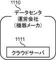
データセンタ運営会社1110には、クラウドサーバ1111が存在する。クラウドサーバ1111は、インターネットを介して様々な機器と連携する仮想化サーバである。クラウドサーバ1111は、主に通常のデータベース管理ツール等で扱うことが困難な巨大なデータ(ビッグデータ)等を管理する。データセンタ運営会社1110は、データ管理及びクラウドサーバ1111の管理を行うデータセンタの運営等を行っている。データセンタ運営会社1110が行っている役務については詳細を後述する。 A
ここで、データセンタ運営会社1110は、データ管理及びクラウドサーバ1111の管理を行うデータセンタの運営等のみを行っている会社に限らない。 Here, the data
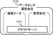
図13B、図13Cは、データセンタ運営会社1110の一例を示す図である。例えば複数の機器1101のうちの一つの機器を開発又は製造している機器メーカが、併せてデータ管理及びクラウドサーバ1111の管理等を行っている場合は、機器メーカがデータセンタ運営会社1110に該当する(図13B)。また、データセンタ運営会社1110は、一つの会社に限らない。例えば機器メーカ及び他の管理会社が共同もしくは分担してデータ管理及びクラウドサーバ1111の管理等を行っている場合は、両者もしくはいずれか一方がデータセンタ運営会社1110に該当するものとする(図13C)。 13B and 13C are diagrams showing an example of the data
サービスプロバイダ1120は、サーバ1121を保有している。ここで言うサーバ1121とは、その規模は問わず例えば、個人用パーソナルコンピュータ内のメモリ等も含む。また、サービスプロバイダ1120がサーバ1121を保有していない場合もある。この場合、サービスプロバイダ1120は、サーバ1121の機能を果たす別の装置を保有する。 The
なお、上記話者識別システムにおいて、ホームゲートウェイ1102は必須ではない。ホームゲートウェイ1102は、機器1101をインターネットに接続可能にするための装置である。そこで、例えば、グループ1100内のあらゆる機器1101がインターネットに接続されている場合のように、それ自身ではインターネットに接続不可能な機器が存在しない場合は、ホームゲートウェイ1102は不要となる。 In the above speaker identification system, the
次に、図13Aを用いて上記話者識別システムにおける情報の流れを説明する。 Next, the flow of information in the above speaker identification system will be described using FIG. 13A.
まず、グループ1100の機器1101、例えば機器A又は機器Bは、各操作ログ情報をデータセンタ運営会社1110のクラウドサーバ1111に送信する。クラウドサーバ1111は、機器A又は機器Bの操作ログ情報を集積する(図13Aの矢印(a))。ここで、操作ログ情報とは複数の機器1101の、例えば運転状況や動作日時等を示す情報である。例えば、テレビの視聴履歴、レコーダの録画予約情報、洗濯機の運転日時及び洗濯物の量、冷蔵庫の開閉日時及び開閉回数などである。操作ログ情報は、これらのものに限らずあらゆる機器1101から取得が可能なすべての情報をいう。 First, the
操作ログ情報は、インターネットを介して複数の機器1101自体から直接クラウドサーバ1111に提供される場合もある。また、複数の機器1101から一旦ホームゲートウェイ1102に操作ログ情報が集積され、ホームゲートウェイ1102からクラウドサーバ1111に提供されてもよい。 Operation log information may be provided to the
次に、データセンタ運営会社1110のクラウドサーバ1111は、集積した操作ログ情報を一定の単位でサービスプロバイダ1120に提供する。ここで、「一定の単位」は、データセンタ運営会社1110が集積した情報を整理してサービスプロバイダ1120に提供することのできる単位でもよく、サービスプロバイダ1120が要求した単位でもよい。「一定の単位」と記載したが、情報量は一定でなくてもよい。例えば、状況に応じて提供する情報量が変化する場合もある。前記操作ログ情報は、必要に応じてサービスプロバイダ1120が保有するサーバ1121に保存される(図13Aの矢印(b))。 Next, the
そして、サービスプロバイダ1120は、操作ログ情報をユーザに提供するサービスに適合する情報に整理し、ユーザに提供する。提供対象のユーザは、複数の機器1101を使用するユーザ1010でもよく、外部のユーザ1020でもよい。ユーザへのサービス提供方法は、例えば、サービスプロバイダ1120から直接ユーザ1010,1020へ提供されてもよい(図13Aの矢印(f)、(e))。また、ユーザへのサービス提供方法は、例えば、データセンタ運営会社1110のクラウドサーバ1111を再度経由して、ユーザ1010に提供されてもよい(図13Aの矢印(c)、(d))。また、データセンタ運営会社1110のクラウドサーバ1111が操作ログ情報をユーザに提供するサービスに適合する情報に整理し、サービスプロバイダ1120に提供してもよい。 Then, the
なお、ユーザ1010とユーザ1020とは、別でも同一でもよい。 The
上記態様において説明された技術は、例えば、以下のクラウドサービスの類型において実現されうる。しかし、上記態様において説明された技術が実現される類型はこれに限られるものでない。 The techniques described in the above aspects may be implemented, for example, in the following cloud service types. However, the type in which the technology described in the above aspect is realized is not limited to this.
(サービスの類型1:自社データセンタ型)
図14は、サービスの類型1(自社データセンタ型)を示す。本類型は、サービスプロバイダ1120がグループ1100から情報を取得し、ユーザに対してサービスを提供する類型である。本類型では、サービスプロバイダ1120が、データセンタ運営会社の機能を有している。即ち、サービスプロバイダ1120が、ビッグデータの管理をするクラウドサーバ1111を保有している。従って、データセンタ運営会社は存在しない。(Service Type 1: In-house data center type)
FIG. 14
本類型では、サービスプロバイダ1120は、データセンタ(クラウドサーバ1111)を運営、管理している(1203)。また、サービスプロバイダ1120は、OS(1202)及びアプリケーション(1201)を管理する。サービスプロバイダ1120は、サービスプロバイダ1120が管理するOS(1202)及びアプリケーション(1201)を用いてサービス提供を行う(1204)。 In this type, the
(サービスの類型2:IaaS利用型)
図15は、サービスの類型2(IaaS利用型)を示す。ここでIaaSとはインフラストラクチャー・アズ・ア・サービスの略であり、コンピュータシステムを構築および稼動させるための基盤そのものを、インターネット経由のサービスとして提供するクラウドサービス提供モデルである。(Service type 2: IaaS usage type)
FIG. 15 shows service type 2 (IaaS usage type). Here, IaaS is an abbreviation of infrastructure as a service, and is a cloud service providing model that provides a platform itself for building and operating a computer system as a service via the Internet.
本類型では、データセンタ運営会社1110がデータセンタ(クラウドサーバ1111)を運営、管理している(1203)。また、サービスプロバイダ1120は、OS(1202)及びアプリケーション(1201)を管理する。サービスプロバイダ1120は、サービスプロバイダ1120が管理するOS(1202)及びアプリケーション(1201)を用いてサービス提供を行う(1204)。 In this type, the data
(サービスの類型3:PaaS利用型)
図16は、サービスの類型3(PaaS利用型)を示す。ここでPaaSとはプラットフォーム・アズ・ア・サービスの略であり、ソフトウェアを構築および稼動させるための土台となるプラットフォームを、インターネット経由のサービスとして提供するクラウドサービス提供モデルである。(Service Type 3: PaaS Type)
FIG. 16 shows service type 3 (PaaS using type). Here, PaaS is an abbreviation of platform as a service, and is a cloud service providing model that provides a platform serving as a foundation for building and operating software as a service via the Internet.
本類型では、データセンタ運営会社1110は、OS(1202)を管理し、データセンタ(クラウドサーバ1111)を運営、管理している(1203)。また、サービスプロバイダ1120は、アプリケーション(1201)を管理する。サービスプロバイダ1120は、データセンタ運営会社1110が管理するOS(1202)及びサービスプロバイダ1120が管理するアプリケーション(1201)を用いてサービス提供を行う(1204)。 In this type, the data
(サービスの類型4:SaaS利用型)
図17は、サービスの類型4(SaaS利用型)を示す。ここでSaaSとはソフトウェア・アズ・ア・サービスの略である。例えばデータセンタ(クラウドサーバ)を保有しているプラットフォーム提供者が提供するアプリケーションを、データセンタ(クラウドサーバ)を保有していない会社・個人(利用者)がインターネットなどのネットワーク経由で使用できる機能を有するクラウドサービス提供モデルである。(Service type 4: SaaS usage type)
FIG. 17 shows service type 4 (SaaS usage type). Here, SaaS is an abbreviation of software as a service. For example, an application provided by a platform provider having a data center (cloud server) can be used by a company / individual (user) who does not have a data center (cloud server) via a network such as the Internet. Cloud service provision model.
本類型では、データセンタ運営会社1110は、アプリケーション(1201)を管理し、OS(1202)を管理し、データセンタ(クラウドサーバ1111)を運営、管理している(1203)。また、サービスプロバイダ1120は、データセンタ運営会社1110が管理するOS(1202)及びアプリケーション(1201)を用いてサービス提供を行う(1204)。 In this type, the data
以上いずれの類型においても、サービスプロバイダ1120がサービス提供行為を行ったものとする。また例えば、サービスプロバイダ1120若しくはデータセンタ運営会社1110は、OS、アプリケーション若しくはビックデータのデータベース等を自ら開発してもよいし、また、第三者に外注して開発させてもよい。 In any of the above types, it is assumed that the
本開示にかかる話者識別方法、話者識別装置及び話者識別システムは、不特定多数の発話者がいる環境において、話者識別を使用する際に、識別されている話者を表す話者画像を容易に表示する方法、装置及びシステムとして有用である。 A speaker identification method, a speaker identification device, and a speaker identification system according to the present disclosure are a speaker representing a speaker being identified when using speaker identification in an environment with an unspecified number of speakers It is useful as a method, apparatus and system for easily displaying an image.
Claims (16)
Translated fromJapanese前記話者識別システムは、複数の話者の音声に基づきそれぞれ生成された複数の登録音声信号と、前記複数の登録音声信号にそれぞれ対応付けられ前記複数の話者をそれぞれ表す複数の話者画像とを保存するデータベースを含み、
前記表示部の周辺に位置する話者の音声を取得し、
前記取得された話者の音声から前記話者の位置を表す位置情報を検出し、
前記取得された話者の音声から話者音声信号を生成し、
前記データベースに保存されている複数の登録音声信号のうち、前記生成された話者音声信号に対応する登録音声信号を識別し、
前記識別された登録音声信号に対応付けて前記データベースに保存されている前記話者画像を、少なくとも前記話者音声信号を生成する元となった前記話者の音声が取得されている間、前記検出された位置情報により表される前記話者の位置に対応した前記表示部上の位置に表示させ、
前記話者画像についての話者からの修正指示が受け付けられると、前記修正を指示した話者の音声を新たに取得し、
前記新たに取得された話者の音声から新たに話者音声信号を生成し、
前記データベースに保存されている、前記修正指示が行われた前記話者画像に対応付けられている前記登録音声信号を、前記新たに生成された話者音声信号に書き換え、
前記話者からの修正指示は、前記表示部に表示されている前記話者画像について受け付けられ、前記表示部に表示されていない前記話者画像については受け付けられない、
話者識別方法。A speaker identification method in a speaker identification system for identifying a voice of a speaker located around a display unit and displaying an identification result on the display unit.
The speaker identification system includes a plurality of registered voice signals respectively generated based on voices of a plurality of speakers, and a plurality of speaker images respectively associated with the plurality of registered voice signals and respectively representing the plurality of speakers. Contains a database to store
Acquiring a voice of a speaker located around the display unit;
Position information representing the position of the speaker is detected from the voice of the acquired speaker;
Generating a speaker voice signal from the voice of the obtained speaker;
Identifying a registered voice signal corresponding to the generated speaker voice signal among the plurality of registered voice signals stored in the database;
The speaker image stored in the database in association with the identified registered voice signal is at least while the voice of the speaker from which the speaker voice signal is generated is acquired. Displaying the position on the display unit corresponding to the position of the speaker represented by the detected position information;
When a correction instruction from the speaker on the speaker image is accepted, a voice of the speaker who instructed the correction is newly acquired,
A speaker speech signal is newly generated from the newly acquired speaker's speech,
Rewriting the registered voice signal stored in the database and associated with the speaker image for which the correction instruction has been given, to the newly generated speaker voice signal;
The correction instruction from the speaker is received for the speaker image displayed on the display unit, and the speaker image not displayed on the display unit is not received.
Speaker identification method.
前記話者画像を、前記表示部上の前記位置情報により表される水平方向の前記話者の位置に表示する、
請求項1に記載の話者識別方法。The position information represents the position of the speaker in the horizontal direction with respect to the display unit,
Displaying the speaker image at the position of the speaker in the horizontal direction represented by the position information on the display unit;
The speaker identification method according to claim 1.
前記話者の音声が取得されている間は第1の表示形式で表示し、
前記話者の音声が取得された後に、前記話者の音声が取得されていない間は、第2の表示形式で表示する、
請求項1に記載の話者識別方法。The speaker image,
While the voice of the speaker is being acquired, it is displayed in the first display format,
After the voice of the speaker is obtained, while the voice of the speaker is not obtained, the second display format is displayed.
The speaker identification method according to claim 1.
前記検出した発話内容を、前記話者音声信号を生成する元となった前記話者の音声が取得されている間、前記話者画像の近傍に表示する、
請求項1に記載の話者識別方法。The utterance content of the speaker is detected from the generated speaker voice signal,
The detected utterance content is displayed in the vicinity of the speaker image while the voice of the speaker from which the speaker voice signal is generated is acquired.
The speaker identification method according to claim 1.
請求項1〜4のいずれか1項に記載の話者識別方法。When a predetermined time elapses from the time when the voice of the speaker from which the speaker voice signal is generated is not obtained, the displayed speaker image is erased from the display unit.
The speaker identification method according to any one of claims 1 to 4.
前記第1話者の音声が取得されると、第1話者音声信号が生成され、
前記生成された第1話者音声信号が前記第1登録音声信号に対応すると識別されると、少なくとも前記第1話者の音声が取得されている間、前記第1話者画像が前記表示部に表示され、
前記第1話者画像が前記表示部に表示されているときに、前記第2話者の音声が取得されると、第2話者音声信号が生成され、
前記生成された第2話者音声信号が前記第2登録音声信号に対応すると識別されると、少なくとも前記第2話者の音声が取得されている間、前記第1話者画像に加えて、前記第2話者画像が前記表示部に表示される、
請求項1〜5のいずれか1項に記載の話者識別方法。The database stores, as the plurality ofregistered speech signals, a first registered speech signal generated based on the speech of the first speaker and a second registered speech signal generated based on the speech of the second speaker And a first speaker image representing the first speaker in association with the first registered audio signal, and a second speaker image representing the second speaker in association with the second registered audio signal Save
When the voice of the first speaker is obtained, a first speaker voice signal is generated,
When it is identified that the generated first speaker voice signal corresponds to the first registered voice signal, the first speaker image is displayed on the display unit while at least the voice of the first speaker is acquired. Displayed on the
When the voice of the second speaker is acquired while the first speaker image is displayed on the display unit, a second speaker voice signal is generated.
When it is identified that the generated second speaker voice signal corresponds to the second registered voice signal, in addition to the first speaker image, at least while the voice of the second speaker is acquired, The second speaker image is displayed on the display unit.
The speaker identification method according to any one of claims 1 to 5.
請求項6に記載の話者識別方法。The first speaker image and the second speaker image are arranged and displayed on the display unit in the order in which the voice of the first speaker and the voice of the second speaker are acquired.
The speaker identification method according to claim 6.
請求項6に記載の話者識別方法。Among the first speaker image and the second speaker image, the speaker image of the one registered later in the database is different from the speaker image of the one registered earlier in the database Displayed on the display unit,
The speaker identification method according to claim 6.
前記第1話者画像と前記第2話者画像とは、前記カウントされた発話回数の多い順に、前記表示部に並べられて表示される、
請求項6に記載の話者識別方法。The number of utterances of the first speaker and the number of utterances of the second speaker are counted,
The first speaker image and the second speaker image are arranged and displayed on the display unit in descending order of the counted number of utterances.
The speaker identification method according to claim 6.
前記判別された前記話者の属性に基づき前記話者画像を作成し、
前記生成された話者音声信号と前記判別された前記話者の属性と前記作成された前記話者画像とを、互いに対応付けて前記データベースに保存し、前記データベースには、前記生成された話者音声信号は、前記登録音声信号として保存される、
請求項1〜9のいずれか1項に記載の話者識別方法。Determining an attribute of the speaker from the generated speaker voice signal;
The speaker image is created based on the determined attribute of the speaker,
The generated speaker voice signal, the attribute of the determined speaker and the generated speaker image are stored in the database in association with each other, and the database stores the generated speech The person's voice signal is stored as the registered voice signal,
The speaker identification method according to any one of claims 1 to 9.
前記表示部の周辺に位置する話者の音声を取得する音声取得部と、
前記取得された話者の音声から話者音声信号を生成する音声処理部と、
複数の話者の音声に基づきそれぞれ生成された複数の登録音声信号と、前記複数の登録音声信号にそれぞれ対応付けられ前記複数の話者をそれぞれ表す複数の話者画像とを記憶するデータベースと、
前記データベースに記憶されている前記複数の登録音声信号のうち、前記生成された前記話者音声信号に対応する登録音声信号を識別する識別処理部と、
前記取得された話者の音声から、前記話者の位置を表す位置情報を検出する位置情報検出部と、
前記識別された前記登録音声信号に対応付けて前記データベースに記憶されている前記話者画像を、少なくとも前記話者音声信号を生成する元となった前記話者の音声を前記音声取得部が取得している間、前記検出された位置情報により表される前記話者の位置に対応した前記表示部上の位置に表示する表示制御部と、
前記話者画像についての話者からの修正指示を、前記表示部に表示されている前記話者画像について受け付け、前記表示部に表示されていない前記話者画像については受け付けない修正制御部と、
を備え、
前記音声取得部は、前記話者画像についての話者からの修正指示が受け付けられると、前記修正を指示した話者の音声を新たに取得し、
前記音声処理部は、前記新たに取得された話者の音声から新たに話者音声信号を生成し、
前記修正制御部は、前記データベースに保存されている、前記修正指示が行われた前記話者画像に対応付けられている前記登録音声信号を、前記新たに生成された話者音声信号に書き換える、
話者識別装置。A display unit,
A voice acquisition unit for acquiring a voice of a speaker located around the display unit;
A voice processing unit that generates a speaker voice signal from the voice of the obtained speaker;
A database storing a plurality of registered speech signals respectively generated based on speech of a plurality of speakers, and a plurality of speaker images respectively associated with the plurality of registration speech signals and respectively representing the plurality of speakers;
An identification processing unit that identifies a registered voice signal corresponding to the generated speaker voice signal among the plurality of registered voice signals stored in the database;
A position information detection unit for detecting position information representing the position of the speaker from the voice of the acquired speaker;
The voice acquiring unit acquires at least the voice of the speaker who has generated the speaker voice signal from the speaker image stored in the database in association with the registered voice signal identified. A display control unit for displaying a position on the display unit corresponding to the position of the speaker represented by the detected position information while the display control unit is operating;
A correction control unit that receives a correction instruction from the speaker for the speaker image for the speaker image displayed on the display unit and does not receive the speaker image not displayed on the display unit;
Equipped with
When the correction instruction from the speaker on the speaker image is accepted, the voice acquisition unit newly acquires the voice of the speaker who instructed the correction;
The voice processing unit newly generates a speaker voice signal from the voice of the newly acquired speaker,
The correction control unit rewrites the registered voice signal, which is stored in the database and is associated with the speaker image for which the correction instruction has been made, into the newly generated speaker voice signal.
Speaker identification device.
前記表示制御部は、前記話者画像を、前記表示部上の前記位置情報により表される水平方向の前記話者の位置に表示する、
請求項11に記載の話者識別装置。The position information represents the position of the speaker in the horizontal direction with respect to the display unit,
The display control unit displays the speaker image at the position of the speaker in the horizontal direction represented by the position information on the display unit.
The speaker identification device according to claim 11.
前記位置情報検出部は、前記音声取得部もしくは前記音声処理部が、取得する音声の指向性を制御することで、前記位置情報を検出する、
請求項11に記載の話者識別装置。One of the voice acquisition unit and the voice processing unit has a function of controlling the directivity of the voice to be acquired,
The position information detection unit detects the position information by controlling the directivity of the sound acquired by the sound acquisition unit or the sound processing unit.
The speaker identification device according to claim 11.
前記表示部の周辺に位置する話者の音声を取得する音声取得部と、
前記取得された話者の音声から話者音声信号を生成する音声処理部と、
前記取得された話者の音声から、前記話者の位置を表す位置情報を検出する位置情報検出部と、
ネットワークを介して外部のサーバ装置と通信を行う通信部と、
前記表示部を制御する表示制御部と、
を備える話者識別装置であって、
前記サーバ装置は、
複数の話者の音声に基づきそれぞれ生成された複数の登録音声信号と、前記複数の登録音声信号にそれぞれ対応付けられ前記複数の話者をそれぞれ表す複数の話者画像とを記憶するデータベースと、
前記データベースに記憶されている前記複数の登録音声信号のうち、前記生成された話者音声信号に対応する登録音声信号を識別する識別処理部と、
を備え、
前記通信部は、前記生成された話者音声信号を前記サーバ装置に送信し、かつ、前記サーバ装置から、前記話者音声信号を基に識別された前記話者を表す話者画像を受信し、
前記表示制御部は、前記受信された話者画像を、少なくとも前記話者音声信号を生成する元となった前記話者の音声を前記音声取得部が取得している間、前記検出された位置情報により表される前記話者の位置に対応した前記表示部上の位置に表示させ、
前記話者識別装置は、
前記話者画像についての話者からの修正指示を、前記表示部に表示されている前記話者画像について受け付け、前記表示部に表示されていない前記話者画像については受け付けない修正制御部をさらに備え、
前記音声取得部は、前記話者画像についての話者からの修正指示が受け付けられると、前記修正を指示した話者の音声を新たに取得し、
前記音声処理部は、前記新たに取得された話者の音声から新たに話者音声信号を生成し、
前記修正制御部は、前記データベースに保存されている、前記修正指示が行われた前記話者画像に対応付けられている前記登録音声信号を、前記新たに生成された話者音声信号に書き換える、
話者識別装置。A display unit,
A voice acquisition unit for acquiring a voice of a speaker located around the display unit;
A voice processing unit that generates a speaker voice signal from the voice of the obtained speaker;
A position information detection unit for detecting position information representing the position of the speaker from the voice of the acquired speaker;
A communication unit that communicates with an external server device via a network;
A display control unit that controls the display unit;
A speaker identification device Ru witha,
The server device is
A database storing a plurality of registered speech signals respectively generated based on speech of a plurality of speakers, and a plurality of speaker images respectively associated with the plurality of registration speech signals and respectively representing the plurality of speakers;
An identification processing unit that identifies a registered voice signal corresponding to the generated speaker voice signal among the plurality of registered voice signals stored in the database;
Equipped with
The communication unit transmits the generated speaker voice signal to the server device, and receives, from the server device, a speaker image representing the speaker identified based on the speaker voice signal. ,
The display control unit detects the position of the received speaker image while the voice acquisition unit acquires at least the voice of the speaker that has generated the speaker voice signal. Displaying at a position on the display unit corresponding to the position of the speaker represented by the information;
The speaker identification device
The correction control unit further receives a correction instruction from the speaker on the speaker image for the speaker image displayed on the display unit and does not receive the speaker image not displayed on the display unit. Equipped
When the correction instruction from the speaker on the speaker image is accepted, the voice acquisition unit newly acquires the voice of the speaker who instructed the correction;
The voice processing unit newly generates a speaker voice signal from the voice of the newly acquired speaker,
The correction control unit rewrites the registered voice signal, which is stored in the database and is associated with the speaker image for which the correction instruction has been made, into the newly generated speaker voice signal.
Speaker identification device.
前記表示制御部は、前記話者画像を、前記表示部上の前記位置情報により表される水平方向の前記話者の位置に表示する、
請求項14に記載の話者識別装置。The position information represents the position of the speaker in the horizontal direction with respect to the display unit,
The display control unit displays the speaker image at the position of the speaker in the horizontal direction represented by the position information on the display unit.
The speaker identification device according to claim 14.
前記位置情報検出部は、前記音声取得部もしくは前記音声処理部が、取得する音声の指向性を制御することで、前記位置情報を検出する、
請求項14に記載の話者識別装置。One of the voice acquisition unit and the voice processing unit has a function of controlling the directivity of the voice to be acquired,
The position information detection unit detects the position information by controlling the directivity of the sound acquired by the sound acquisition unit or the sound processing unit.
The speaker identification device according to claim 14.
Applications Claiming Priority (3)
| Application Number | Priority Date | Filing Date | Title |
|---|---|---|---|
| JP2013121714 | 2013-06-10 | ||
| JP2013121714 | 2013-06-10 | ||
| PCT/JP2014/002970WO2014199596A1 (en) | 2013-06-10 | 2014-06-04 | Speaker identification method, speaker identification device, and speaker identification system |
Publications (2)
| Publication Number | Publication Date |
|---|---|
| JPWO2014199596A1 JPWO2014199596A1 (en) | 2017-02-23 |
| JP6534926B2true JP6534926B2 (en) | 2019-06-26 |
Family
ID=52021914
Family Applications (1)
| Application Number | Title | Priority Date | Filing Date |
|---|---|---|---|
| JP2015522523AActiveJP6534926B2 (en) | 2013-06-10 | 2014-06-04 | Speaker identification method, speaker identification device and speaker identification system |
Country Status (3)
| Country | Link |
|---|---|
| US (1) | US9710219B2 (en) |
| JP (1) | JP6534926B2 (en) |
| WO (1) | WO2014199596A1 (en) |
Families Citing this family (80)
| Publication number | Priority date | Publication date | Assignee | Title |
|---|---|---|---|---|
| US9318108B2 (en) | 2010-01-18 | 2016-04-19 | Apple Inc. | Intelligent automated assistant |
| US8977255B2 (en) | 2007-04-03 | 2015-03-10 | Apple Inc. | Method and system for operating a multi-function portable electronic device using voice-activation |
| US8676904B2 (en) | 2008-10-02 | 2014-03-18 | Apple Inc. | Electronic devices with voice command and contextual data processing capabilities |
| US20120309363A1 (en) | 2011-06-03 | 2012-12-06 | Apple Inc. | Triggering notifications associated with tasks items that represent tasks to perform |
| US10276170B2 (en) | 2010-01-18 | 2019-04-30 | Apple Inc. | Intelligent automated assistant |
| US10417037B2 (en) | 2012-05-15 | 2019-09-17 | Apple Inc. | Systems and methods for integrating third party services with a digital assistant |
| DE212014000045U1 (en) | 2013-02-07 | 2015-09-24 | Apple Inc. | Voice trigger for a digital assistant |
| US10652394B2 (en) | 2013-03-14 | 2020-05-12 | Apple Inc. | System and method for processing voicemail |
| US10748529B1 (en) | 2013-03-15 | 2020-08-18 | Apple Inc. | Voice activated device for use with a voice-based digital assistant |
| US10176167B2 (en) | 2013-06-09 | 2019-01-08 | Apple Inc. | System and method for inferring user intent from speech inputs |
| DE112014002747T5 (en) | 2013-06-09 | 2016-03-03 | Apple Inc. | Apparatus, method and graphical user interface for enabling conversation persistence over two or more instances of a digital assistant |
| DE112014003653B4 (en) | 2013-08-06 | 2024-04-18 | Apple Inc. | Automatically activate intelligent responses based on activities from remote devices |
| US10164921B2 (en)* | 2014-03-12 | 2018-12-25 | Stephen Davies | System and method for voice networking |
| CN110797019B (en) | 2014-05-30 | 2023-08-29 | 苹果公司 | Multi-command single speech input method |
| US10170123B2 (en) | 2014-05-30 | 2019-01-01 | Apple Inc. | Intelligent assistant for home automation |
| US9715875B2 (en) | 2014-05-30 | 2017-07-25 | Apple Inc. | Reducing the need for manual start/end-pointing and trigger phrases |
| WO2015186445A1 (en)* | 2014-06-03 | 2015-12-10 | ソニー株式会社 | Information processing device, information processing method, and program |
| US9338493B2 (en) | 2014-06-30 | 2016-05-10 | Apple Inc. | Intelligent automated assistant for TV user interactions |
| JP6464411B6 (en)* | 2015-02-25 | 2019-03-13 | Dynabook株式会社 | Electronic device, method and program |
| US9886953B2 (en) | 2015-03-08 | 2018-02-06 | Apple Inc. | Virtual assistant activation |
| US10460227B2 (en) | 2015-05-15 | 2019-10-29 | Apple Inc. | Virtual assistant in a communication session |
| US10200824B2 (en) | 2015-05-27 | 2019-02-05 | Apple Inc. | Systems and methods for proactively identifying and surfacing relevant content on a touch-sensitive device |
| US20160378747A1 (en) | 2015-06-29 | 2016-12-29 | Apple Inc. | Virtual assistant for media playback |
| US10089061B2 (en) | 2015-08-28 | 2018-10-02 | Kabushiki Kaisha Toshiba | Electronic device and method |
| US10671428B2 (en) | 2015-09-08 | 2020-06-02 | Apple Inc. | Distributed personal assistant |
| US10331312B2 (en) | 2015-09-08 | 2019-06-25 | Apple Inc. | Intelligent automated assistant in a media environment |
| US10740384B2 (en) | 2015-09-08 | 2020-08-11 | Apple Inc. | Intelligent automated assistant for media search and playback |
| US10747498B2 (en) | 2015-09-08 | 2020-08-18 | Apple Inc. | Zero latency digital assistant |
| US20170075652A1 (en) | 2015-09-14 | 2017-03-16 | Kabushiki Kaisha Toshiba | Electronic device and method |
| US11587559B2 (en) | 2015-09-30 | 2023-02-21 | Apple Inc. | Intelligent device identification |
| US10691473B2 (en) | 2015-11-06 | 2020-06-23 | Apple Inc. | Intelligent automated assistant in a messaging environment |
| US10956666B2 (en) | 2015-11-09 | 2021-03-23 | Apple Inc. | Unconventional virtual assistant interactions |
| US10223066B2 (en) | 2015-12-23 | 2019-03-05 | Apple Inc. | Proactive assistance based on dialog communication between devices |
| US12223282B2 (en) | 2016-06-09 | 2025-02-11 | Apple Inc. | Intelligent automated assistant in a home environment |
| US10586535B2 (en) | 2016-06-10 | 2020-03-10 | Apple Inc. | Intelligent digital assistant in a multi-tasking environment |
| DK179415B1 (en) | 2016-06-11 | 2018-06-14 | Apple Inc | Intelligent device arbitration and control |
| US12197817B2 (en) | 2016-06-11 | 2025-01-14 | Apple Inc. | Intelligent device arbitration and control |
| DK201670540A1 (en) | 2016-06-11 | 2018-01-08 | Apple Inc | Application integration with a digital assistant |
| US10516938B2 (en)* | 2016-07-16 | 2019-12-24 | Ron Zass | System and method for assessing speaker spatial orientation |
| KR102596430B1 (en)* | 2016-08-31 | 2023-10-31 | 삼성전자주식회사 | Method and apparatus for speech recognition based on speaker recognition |
| JP6659514B2 (en) | 2016-10-12 | 2020-03-04 | 東芝映像ソリューション株式会社 | Electronic device and control method thereof |
| WO2018101458A1 (en)* | 2016-12-02 | 2018-06-07 | ヤマハ株式会社 | Sound collection device, content playback device, and content playback system |
| JP6760394B2 (en) | 2016-12-02 | 2020-09-23 | ヤマハ株式会社 | Content playback equipment, sound collection equipment, and content playback system |
| US11204787B2 (en) | 2017-01-09 | 2021-12-21 | Apple Inc. | Application integration with a digital assistant |
| US10726832B2 (en) | 2017-05-11 | 2020-07-28 | Apple Inc. | Maintaining privacy of personal information |
| DK180048B1 (en) | 2017-05-11 | 2020-02-04 | Apple Inc. | MAINTAINING THE DATA PROTECTION OF PERSONAL INFORMATION |
| DK179496B1 (en) | 2017-05-12 | 2019-01-15 | Apple Inc. | USER-SPECIFIC Acoustic Models |
| DK201770427A1 (en) | 2017-05-12 | 2018-12-20 | Apple Inc. | Low-latency intelligent automated assistant |
| DK179745B1 (en) | 2017-05-12 | 2019-05-01 | Apple Inc. | SYNCHRONIZATION AND TASK DELEGATION OF A DIGITAL ASSISTANT |
| DK201770411A1 (en) | 2017-05-15 | 2018-12-20 | Apple Inc. | MULTI-MODAL INTERFACES |
| US10303715B2 (en) | 2017-05-16 | 2019-05-28 | Apple Inc. | Intelligent automated assistant for media exploration |
| US20180336892A1 (en) | 2017-05-16 | 2018-11-22 | Apple Inc. | Detecting a trigger of a digital assistant |
| DK179549B1 (en) | 2017-05-16 | 2019-02-12 | Apple Inc. | Far-field extension for digital assistant services |
| US10818288B2 (en) | 2018-03-26 | 2020-10-27 | Apple Inc. | Natural assistant interaction |
| US11145294B2 (en) | 2018-05-07 | 2021-10-12 | Apple Inc. | Intelligent automated assistant for delivering content from user experiences |
| US10928918B2 (en) | 2018-05-07 | 2021-02-23 | Apple Inc. | Raise to speak |
| CN108965967A (en)* | 2018-05-25 | 2018-12-07 | 苏州浪潮智能软件有限公司 | TV control method and device, computer readable storage medium, terminal |
| US10892996B2 (en) | 2018-06-01 | 2021-01-12 | Apple Inc. | Variable latency device coordination |
| DK180639B1 (en) | 2018-06-01 | 2021-11-04 | Apple Inc | DISABILITY OF ATTENTION-ATTENTIVE VIRTUAL ASSISTANT |
| DK179822B1 (en) | 2018-06-01 | 2019-07-12 | Apple Inc. | Voice interaction at a primary device to access call functionality of a companion device |
| DK201870355A1 (en) | 2018-06-01 | 2019-12-16 | Apple Inc. | Virtual assistant operation in multi-device environments |
| CN108882032A (en)* | 2018-06-08 | 2018-11-23 | 百度在线网络技术(北京)有限公司 | Method and apparatus for output information |
| US11462215B2 (en) | 2018-09-28 | 2022-10-04 | Apple Inc. | Multi-modal inputs for voice commands |
| RU2744063C1 (en)* | 2018-12-18 | 2021-03-02 | Общество С Ограниченной Ответственностью "Яндекс" | Method and system for determining speaking user of voice-controlled device |
| US11348573B2 (en) | 2019-03-18 | 2022-05-31 | Apple Inc. | Multimodality in digital assistant systems |
| DK201970509A1 (en) | 2019-05-06 | 2021-01-15 | Apple Inc | Spoken notifications |
| US11307752B2 (en) | 2019-05-06 | 2022-04-19 | Apple Inc. | User configurable task triggers |
| US11140099B2 (en) | 2019-05-21 | 2021-10-05 | Apple Inc. | Providing message response suggestions |
| DK180129B1 (en) | 2019-05-31 | 2020-06-02 | Apple Inc. | USER ACTIVITY SHORTCUT SUGGESTIONS |
| DK201970511A1 (en) | 2019-05-31 | 2021-02-15 | Apple Inc | Voice identification in digital assistant systems |
| US11227599B2 (en) | 2019-06-01 | 2022-01-18 | Apple Inc. | Methods and user interfaces for voice-based control of electronic devices |
| CN112466306B (en)* | 2019-08-19 | 2023-07-04 | 中国科学院自动化研究所 | Method, device, computer equipment and storage medium for generating meeting minutes |
| JP6977004B2 (en)* | 2019-08-23 | 2021-12-08 | サウンドハウンド,インコーポレイテッド | In-vehicle devices, methods and programs for processing vocalizations |
| US12301635B2 (en) | 2020-05-11 | 2025-05-13 | Apple Inc. | Digital assistant hardware abstraction |
| US11183193B1 (en) | 2020-05-11 | 2021-11-23 | Apple Inc. | Digital assistant hardware abstraction |
| US11061543B1 (en) | 2020-05-11 | 2021-07-13 | Apple Inc. | Providing relevant data items based on context |
| US11755276B2 (en) | 2020-05-12 | 2023-09-12 | Apple Inc. | Reducing description length based on confidence |
| US11490204B2 (en) | 2020-07-20 | 2022-11-01 | Apple Inc. | Multi-device audio adjustment coordination |
| US11438683B2 (en) | 2020-07-21 | 2022-09-06 | Apple Inc. | User identification using headphones |
| WO2024158070A1 (en)* | 2023-01-27 | 2024-08-02 | 주식회사 엔씨소프트 | Method, apparatus, and computer-readable recording medium for visualizing utterer in voice chat service |
Family Cites Families (36)
| Publication number | Priority date | Publication date | Assignee | Title |
|---|---|---|---|---|
| JPH10198393A (en) | 1997-01-08 | 1998-07-31 | Matsushita Electric Ind Co Ltd | Conversation recorder |
| US7117157B1 (en)* | 1999-03-26 | 2006-10-03 | Canon Kabushiki Kaisha | Processing apparatus for determining which person in a group is speaking |
| JP2001314649A (en) | 2000-05-11 | 2001-11-13 | Seta Corp | Voice game method and apparatus, and recording medium |
| JP3953258B2 (en) | 2000-05-30 | 2007-08-08 | シャープ株式会社 | Communication terminal device |
| JP2002341890A (en) | 2001-05-17 | 2002-11-29 | Matsushita Electric Ind Co Ltd | Speech recognition character display method and device |
| US7440900B2 (en)* | 2002-03-15 | 2008-10-21 | Microsoft Corporation | Voice message processing system and method |
| JP2004056286A (en) | 2002-07-17 | 2004-02-19 | Fuji Photo Film Co Ltd | Image display method |
| US6882971B2 (en)* | 2002-07-18 | 2005-04-19 | General Instrument Corporation | Method and apparatus for improving listener differentiation of talkers during a conference call |
| JP4141782B2 (en)* | 2002-09-30 | 2008-08-27 | 株式会社ピートゥピーエー | Image display device, image display method, and program |
| US20060136224A1 (en)* | 2004-12-22 | 2006-06-22 | Eaton William C | Communications devices including positional circuits and methods of operating the same |
| JP4599244B2 (en)* | 2005-07-13 | 2010-12-15 | キヤノン株式会社 | Apparatus and method for creating subtitles from moving image data, program, and storage medium |
| JPWO2007058135A1 (en) | 2005-11-16 | 2009-04-30 | 日本電気株式会社 | Portable terminal device, participant list display method used therefor, and program thereof |
| US8385233B2 (en)* | 2007-06-12 | 2013-02-26 | Microsoft Corporation | Active speaker identification |
| US20090037826A1 (en)* | 2007-07-31 | 2009-02-05 | Christopher Lee Bennetts | Video conferencing system |
| US8243902B2 (en)* | 2007-09-27 | 2012-08-14 | Siemens Enterprise Communications, Inc. | Method and apparatus for mapping of conference call participants using positional presence |
| US7995732B2 (en)* | 2007-10-04 | 2011-08-09 | At&T Intellectual Property I, Lp | Managing audio in a multi-source audio environment |
| JP2009206924A (en)* | 2008-02-28 | 2009-09-10 | Fuji Xerox Co Ltd | Information processing apparatus, information processing system and information processing program |
| US8503653B2 (en)* | 2008-03-03 | 2013-08-06 | Alcatel Lucent | Method and apparatus for active speaker selection using microphone arrays and speaker recognition |
| US8316089B2 (en)* | 2008-05-06 | 2012-11-20 | Microsoft Corporation | Techniques to manage media content for a multimedia conference event |
| US8315366B2 (en)* | 2008-07-22 | 2012-11-20 | Shoretel, Inc. | Speaker identification and representation for a phone |
| JP4941486B2 (en) | 2009-03-13 | 2012-05-30 | ミツミ電機株式会社 | Digital broadcast receiving apparatus and information providing method in digital broadcast |
| JP5413033B2 (en) | 2009-08-03 | 2014-02-12 | 株式会社リコー | Information processing apparatus, information leakage prevention method and program |
| US20110093266A1 (en)* | 2009-10-15 | 2011-04-21 | Tham Krister | Voice pattern tagged contacts |
| US9197736B2 (en) | 2009-12-31 | 2015-11-24 | Digimarc Corporation | Intuitive computing methods and systems |
| US20120154633A1 (en) | 2009-12-04 | 2012-06-21 | Rodriguez Tony F | Linked Data Methods and Systems |
| WO2011116309A1 (en)* | 2010-03-19 | 2011-09-22 | Digimarc Corporation | Intuitive computing methods and systems |
| US8660355B2 (en) | 2010-03-19 | 2014-02-25 | Digimarc Corporation | Methods and systems for determining image processing operations relevant to particular imagery |
| EP2405365B1 (en)* | 2010-07-09 | 2013-06-19 | Sony Ericsson Mobile Communications AB | Method and device for mnemonic contact image association |
| WO2012169679A1 (en)* | 2011-06-10 | 2012-12-13 | 엘지전자 주식회사 | Display apparatus, method for controlling display apparatus, and voice recognition system for display apparatus |
| WO2013022135A1 (en)* | 2011-08-11 | 2013-02-14 | Lg Electronics Inc. | Electronic device and method of controlling the same |
| US8934652B2 (en)* | 2011-12-01 | 2015-01-13 | Elwha Llc | Visual presentation of speaker-related information |
| US20130162752A1 (en)* | 2011-12-22 | 2013-06-27 | Advanced Micro Devices, Inc. | Audio and Video Teleconferencing Using Voiceprints and Face Prints |
| JP5743976B2 (en)* | 2012-08-10 | 2015-07-01 | 株式会社東芝 | Information processing apparatus, program, and information processing method |
| US20140114664A1 (en)* | 2012-10-20 | 2014-04-24 | Microsoft Corporation | Active Participant History in a Video Conferencing System |
| US9679564B2 (en)* | 2012-12-12 | 2017-06-13 | Nuance Communications, Inc. | Human transcriptionist directed posterior audio source separation |
| US9223340B2 (en)* | 2013-08-14 | 2015-12-29 | Lenovo (Singapore) Pte. Ltd. | Organizing display data on a multiuser display |
- 2014
- 2014-06-04JPJP2015522523Apatent/JP6534926B2/enactiveActive
- 2014-06-04WOPCT/JP2014/002970patent/WO2014199596A1/enactiveApplication Filing
- 2014-06-04USUS14/420,749patent/US9710219B2/enactiveActive
Also Published As
| Publication number | Publication date |
|---|---|
| WO2014199596A1 (en) | 2014-12-18 |
| US20150205568A1 (en) | 2015-07-23 |
| JPWO2014199596A1 (en) | 2017-02-23 |
| US9710219B2 (en) | 2017-07-18 |
Similar Documents
| Publication | Publication Date | Title |
|---|---|---|
| JP6534926B2 (en) | Speaker identification method, speaker identification device and speaker identification system | |
| JP6482911B2 (en) | Device control method and electric device | |
| CN106024009B (en) | Audio processing method and device | |
| EP2674941B1 (en) | Terminal apparatus and control method thereof | |
| JP6178198B2 (en) | Speech translation system, method and program | |
| KR102339657B1 (en) | Electronic device and control method thereof | |
| JPWO2017168936A1 (en) | Information processing apparatus, information processing method, and program | |
| US12003804B2 (en) | Information processing device, information processing method, and computer program | |
| EP3419020B1 (en) | Information processing device, information processing method and program | |
| CN106257355A (en) | Apparatus control method and controller | |
| JP6120927B2 (en) | Dialog system, method for controlling dialog, and program for causing computer to function as dialog system | |
| WO2018036392A1 (en) | Voice-based information sharing method, device, and mobile terminal | |
| KR20140055502A (en) | Broadcast receiving apparatus, server and control method thereof | |
| CN107945806B (en) | User identification method and device based on sound characteristics | |
| WO2022026010A1 (en) | Intelligent captioning | |
| JP6278403B2 (en) | Karaoke management system | |
| US20190035420A1 (en) | Information processing device, information processing method, and program | |
| WO2020024436A1 (en) | Method and system for updating user information, and server | |
| KR20140111574A (en) | Apparatus and method for performing an action according to an audio command | |
| US20200349825A1 (en) | Information processing apparatus and information processing method | |
| CN107068125A (en) | Musical instrument control method and device | |
| US12149796B2 (en) | Smart content search from audio/video captures while watching tv content itself | |
| CN116095377A (en) | Remote controller control method and device based on voice recognition and electronic equipment |
Legal Events
| Date | Code | Title | Description |
|---|---|---|---|
| A524 | Written submission of copy of amendment under article 19 pct | Free format text:JAPANESE INTERMEDIATE CODE: A527 Effective date:20150206 | |
| A621 | Written request for application examination | Free format text:JAPANESE INTERMEDIATE CODE: A621 Effective date:20161221 | |
| A131 | Notification of reasons for refusal | Free format text:JAPANESE INTERMEDIATE CODE: A131 Effective date:20180227 | |
| A521 | Request for written amendment filed | Free format text:JAPANESE INTERMEDIATE CODE: A523 Effective date:20180514 | |
| A131 | Notification of reasons for refusal | Free format text:JAPANESE INTERMEDIATE CODE: A131 Effective date:20181002 | |
| A521 | Request for written amendment filed | Free format text:JAPANESE INTERMEDIATE CODE: A523 Effective date:20181207 | |
| TRDD | Decision of grant or rejection written | ||
| A01 | Written decision to grant a patent or to grant a registration (utility model) | Free format text:JAPANESE INTERMEDIATE CODE: A01 Effective date:20190521 | |
| A61 | First payment of annual fees (during grant procedure) | Free format text:JAPANESE INTERMEDIATE CODE: A61 Effective date:20190530 | |
| R150 | Certificate of patent or registration of utility model | Ref document number:6534926 Country of ref document:JP Free format text:JAPANESE INTERMEDIATE CODE: R150 |