JP6534385B2 - Stent - Google Patents
StentDownload PDFInfo
- Publication number
- JP6534385B2 JP6534385B2JP2016521056AJP2016521056AJP6534385B2JP 6534385 B2JP6534385 B2JP 6534385B2JP 2016521056 AJP2016521056 AJP 2016521056AJP 2016521056 AJP2016521056 AJP 2016521056AJP 6534385 B2JP6534385 B2JP 6534385B2
- Authority
- JP
- Japan
- Prior art keywords
- stent
- valve body
- aneurysm
- catheter
- insertion portion
- Prior art date
- Legal status (The legal status is an assumption and is not a legal conclusion. Google has not performed a legal analysis and makes no representation as to the accuracy of the status listed.)
- Active
Links
- 230000037431insertionEffects0.000claimsdescription74
- 238000003780insertionMethods0.000claimsdescription74
- 206010002329AneurysmDiseases0.000claimsdescription41
- 210000004204blood vesselAnatomy0.000claimsdescription28
- 230000002093peripheral effectEffects0.000claimsdescription17
- 239000000463materialSubstances0.000claimsdescription10
- 239000000126substanceSubstances0.000claimsdescription3
- 239000008280bloodSubstances0.000description4
- 210000004369bloodAnatomy0.000description4
- 230000003073embolic effectEffects0.000description4
- 230000010102embolizationEffects0.000description4
- 208000007536ThrombosisDiseases0.000description3
- 230000015572biosynthetic processEffects0.000description3
- 229910045601alloyInorganic materials0.000description2
- 239000000956alloySubstances0.000description2
- 238000005452bendingMethods0.000description2
- 238000005516engineering processMethods0.000description1
- 239000012528membraneSubstances0.000description1
- 239000010935stainless steelSubstances0.000description1
- 229910001220stainless steelInorganic materials0.000description1
Images


Classifications
- A—HUMAN NECESSITIES
- A61—MEDICAL OR VETERINARY SCIENCE; HYGIENE
- A61B—DIAGNOSIS; SURGERY; IDENTIFICATION
- A61B17/00—Surgical instruments, devices or methods
- A61B17/12—Surgical instruments, devices or methods for ligaturing or otherwise compressing tubular parts of the body, e.g. blood vessels or umbilical cord
- A61B17/12022—Occluding by internal devices, e.g. balloons or releasable wires
- A61B17/12099—Occluding by internal devices, e.g. balloons or releasable wires characterised by the location of the occluder
- A61B17/12109—Occluding by internal devices, e.g. balloons or releasable wires characterised by the location of the occluder in a blood vessel
- A61B17/12113—Occluding by internal devices, e.g. balloons or releasable wires characterised by the location of the occluder in a blood vessel within an aneurysm
- A61B17/12118—Occluding by internal devices, e.g. balloons or releasable wires characterised by the location of the occluder in a blood vessel within an aneurysm for positioning in conjunction with a stent
- A—HUMAN NECESSITIES
- A61—MEDICAL OR VETERINARY SCIENCE; HYGIENE
- A61B—DIAGNOSIS; SURGERY; IDENTIFICATION
- A61B17/00—Surgical instruments, devices or methods
- A61B17/00491—Surgical glue applicators
- A—HUMAN NECESSITIES
- A61—MEDICAL OR VETERINARY SCIENCE; HYGIENE
- A61B—DIAGNOSIS; SURGERY; IDENTIFICATION
- A61B17/00—Surgical instruments, devices or methods
- A61B17/12—Surgical instruments, devices or methods for ligaturing or otherwise compressing tubular parts of the body, e.g. blood vessels or umbilical cord
- A61B17/12022—Occluding by internal devices, e.g. balloons or releasable wires
- A61B17/12131—Occluding by internal devices, e.g. balloons or releasable wires characterised by the type of occluding device
- A61B17/1214—Coils or wires
- A—HUMAN NECESSITIES
- A61—MEDICAL OR VETERINARY SCIENCE; HYGIENE
- A61B—DIAGNOSIS; SURGERY; IDENTIFICATION
- A61B17/00—Surgical instruments, devices or methods
- A61B17/12—Surgical instruments, devices or methods for ligaturing or otherwise compressing tubular parts of the body, e.g. blood vessels or umbilical cord
- A61B17/12022—Occluding by internal devices, e.g. balloons or releasable wires
- A61B17/12131—Occluding by internal devices, e.g. balloons or releasable wires characterised by the type of occluding device
- A61B17/12168—Occluding by internal devices, e.g. balloons or releasable wires characterised by the type of occluding device having a mesh structure
- A61B17/12172—Occluding by internal devices, e.g. balloons or releasable wires characterised by the type of occluding device having a mesh structure having a pre-set deployed three-dimensional shape
- A—HUMAN NECESSITIES
- A61—MEDICAL OR VETERINARY SCIENCE; HYGIENE
- A61F—FILTERS IMPLANTABLE INTO BLOOD VESSELS; PROSTHESES; DEVICES PROVIDING PATENCY TO, OR PREVENTING COLLAPSING OF, TUBULAR STRUCTURES OF THE BODY, e.g. STENTS; ORTHOPAEDIC, NURSING OR CONTRACEPTIVE DEVICES; FOMENTATION; TREATMENT OR PROTECTION OF EYES OR EARS; BANDAGES, DRESSINGS OR ABSORBENT PADS; FIRST-AID KITS
- A61F2/00—Filters implantable into blood vessels; Prostheses, i.e. artificial substitutes or replacements for parts of the body; Appliances for connecting them with the body; Devices providing patency to, or preventing collapsing of, tubular structures of the body, e.g. stents
- A61F2/82—Devices providing patency to, or preventing collapsing of, tubular structures of the body, e.g. stents
- A61F2/86—Stents in a form characterised by the wire-like elements; Stents in the form characterised by a net-like or mesh-like structure
- A61F2/90—Stents in a form characterised by the wire-like elements; Stents in the form characterised by a net-like or mesh-like structure characterised by a net-like or mesh-like structure
- A—HUMAN NECESSITIES
- A61—MEDICAL OR VETERINARY SCIENCE; HYGIENE
- A61B—DIAGNOSIS; SURGERY; IDENTIFICATION
- A61B17/00—Surgical instruments, devices or methods
- A61B17/00491—Surgical glue applicators
- A61B2017/00495—Surgical glue applicators for two-component glue
- A—HUMAN NECESSITIES
- A61—MEDICAL OR VETERINARY SCIENCE; HYGIENE
- A61B—DIAGNOSIS; SURGERY; IDENTIFICATION
- A61B17/00—Surgical instruments, devices or methods
- A61B17/00491—Surgical glue applicators
- A61B2017/00522—Sprayers
- A—HUMAN NECESSITIES
- A61—MEDICAL OR VETERINARY SCIENCE; HYGIENE
- A61B—DIAGNOSIS; SURGERY; IDENTIFICATION
- A61B17/00—Surgical instruments, devices or methods
- A61B17/12—Surgical instruments, devices or methods for ligaturing or otherwise compressing tubular parts of the body, e.g. blood vessels or umbilical cord
- A61B17/12022—Occluding by internal devices, e.g. balloons or releasable wires
- A61B2017/1205—Introduction devices
- A—HUMAN NECESSITIES
- A61—MEDICAL OR VETERINARY SCIENCE; HYGIENE
- A61F—FILTERS IMPLANTABLE INTO BLOOD VESSELS; PROSTHESES; DEVICES PROVIDING PATENCY TO, OR PREVENTING COLLAPSING OF, TUBULAR STRUCTURES OF THE BODY, e.g. STENTS; ORTHOPAEDIC, NURSING OR CONTRACEPTIVE DEVICES; FOMENTATION; TREATMENT OR PROTECTION OF EYES OR EARS; BANDAGES, DRESSINGS OR ABSORBENT PADS; FIRST-AID KITS
- A61F2/00—Filters implantable into blood vessels; Prostheses, i.e. artificial substitutes or replacements for parts of the body; Appliances for connecting them with the body; Devices providing patency to, or preventing collapsing of, tubular structures of the body, e.g. stents
- A61F2/02—Prostheses implantable into the body
- A61F2/24—Heart valves ; Vascular valves, e.g. venous valves; Heart implants, e.g. passive devices for improving the function of the native valve or the heart muscle; Transmyocardial revascularisation [TMR] devices; Valves implantable in the body
- A61F2/2412—Heart valves ; Vascular valves, e.g. venous valves; Heart implants, e.g. passive devices for improving the function of the native valve or the heart muscle; Transmyocardial revascularisation [TMR] devices; Valves implantable in the body with soft flexible valve members, e.g. tissue valves shaped like natural valves
- A61F2/2418—Scaffolds therefor, e.g. support stents
- A—HUMAN NECESSITIES
- A61—MEDICAL OR VETERINARY SCIENCE; HYGIENE
- A61F—FILTERS IMPLANTABLE INTO BLOOD VESSELS; PROSTHESES; DEVICES PROVIDING PATENCY TO, OR PREVENTING COLLAPSING OF, TUBULAR STRUCTURES OF THE BODY, e.g. STENTS; ORTHOPAEDIC, NURSING OR CONTRACEPTIVE DEVICES; FOMENTATION; TREATMENT OR PROTECTION OF EYES OR EARS; BANDAGES, DRESSINGS OR ABSORBENT PADS; FIRST-AID KITS
- A61F2/00—Filters implantable into blood vessels; Prostheses, i.e. artificial substitutes or replacements for parts of the body; Appliances for connecting them with the body; Devices providing patency to, or preventing collapsing of, tubular structures of the body, e.g. stents
- A61F2/02—Prostheses implantable into the body
- A61F2/04—Hollow or tubular parts of organs, e.g. bladders, tracheae, bronchi or bile ducts
- A61F2/06—Blood vessels
- A61F2002/061—Blood vessels provided with means for allowing access to secondary lumens
- A—HUMAN NECESSITIES
- A61—MEDICAL OR VETERINARY SCIENCE; HYGIENE
- A61F—FILTERS IMPLANTABLE INTO BLOOD VESSELS; PROSTHESES; DEVICES PROVIDING PATENCY TO, OR PREVENTING COLLAPSING OF, TUBULAR STRUCTURES OF THE BODY, e.g. STENTS; ORTHOPAEDIC, NURSING OR CONTRACEPTIVE DEVICES; FOMENTATION; TREATMENT OR PROTECTION OF EYES OR EARS; BANDAGES, DRESSINGS OR ABSORBENT PADS; FIRST-AID KITS
- A61F2/00—Filters implantable into blood vessels; Prostheses, i.e. artificial substitutes or replacements for parts of the body; Appliances for connecting them with the body; Devices providing patency to, or preventing collapsing of, tubular structures of the body, e.g. stents
- A61F2/82—Devices providing patency to, or preventing collapsing of, tubular structures of the body, e.g. stents
- A61F2002/823—Stents, different from stent-grafts, adapted to cover an aneurysm
- A—HUMAN NECESSITIES
- A61—MEDICAL OR VETERINARY SCIENCE; HYGIENE
- A61F—FILTERS IMPLANTABLE INTO BLOOD VESSELS; PROSTHESES; DEVICES PROVIDING PATENCY TO, OR PREVENTING COLLAPSING OF, TUBULAR STRUCTURES OF THE BODY, e.g. STENTS; ORTHOPAEDIC, NURSING OR CONTRACEPTIVE DEVICES; FOMENTATION; TREATMENT OR PROTECTION OF EYES OR EARS; BANDAGES, DRESSINGS OR ABSORBENT PADS; FIRST-AID KITS
- A61F2230/00—Geometry of prostheses classified in groups A61F2/00 - A61F2/26 or A61F2/82 or A61F9/00 or A61F11/00 or subgroups thereof
- A61F2230/0002—Two-dimensional shapes, e.g. cross-sections
- A61F2230/0017—Angular shapes
- A61F2230/0023—Angular shapes triangular
- A—HUMAN NECESSITIES
- A61—MEDICAL OR VETERINARY SCIENCE; HYGIENE
- A61F—FILTERS IMPLANTABLE INTO BLOOD VESSELS; PROSTHESES; DEVICES PROVIDING PATENCY TO, OR PREVENTING COLLAPSING OF, TUBULAR STRUCTURES OF THE BODY, e.g. STENTS; ORTHOPAEDIC, NURSING OR CONTRACEPTIVE DEVICES; FOMENTATION; TREATMENT OR PROTECTION OF EYES OR EARS; BANDAGES, DRESSINGS OR ABSORBENT PADS; FIRST-AID KITS
- A61F2250/00—Special features of prostheses classified in groups A61F2/00 - A61F2/26 or A61F2/82 or A61F9/00 or A61F11/00 or subgroups thereof
- A61F2250/0014—Special features of prostheses classified in groups A61F2/00 - A61F2/26 or A61F2/82 or A61F9/00 or A61F11/00 or subgroups thereof having different values of a given property or geometrical feature, e.g. mechanical property or material property, at different locations within the same prosthesis
- A61F2250/0018—Special features of prostheses classified in groups A61F2/00 - A61F2/26 or A61F2/82 or A61F9/00 or A61F11/00 or subgroups thereof having different values of a given property or geometrical feature, e.g. mechanical property or material property, at different locations within the same prosthesis differing in elasticity, stiffness or compressibility
- A—HUMAN NECESSITIES
- A61—MEDICAL OR VETERINARY SCIENCE; HYGIENE
- A61F—FILTERS IMPLANTABLE INTO BLOOD VESSELS; PROSTHESES; DEVICES PROVIDING PATENCY TO, OR PREVENTING COLLAPSING OF, TUBULAR STRUCTURES OF THE BODY, e.g. STENTS; ORTHOPAEDIC, NURSING OR CONTRACEPTIVE DEVICES; FOMENTATION; TREATMENT OR PROTECTION OF EYES OR EARS; BANDAGES, DRESSINGS OR ABSORBENT PADS; FIRST-AID KITS
- A61F2250/00—Special features of prostheses classified in groups A61F2/00 - A61F2/26 or A61F2/82 or A61F9/00 or A61F11/00 or subgroups thereof
- A61F2250/0014—Special features of prostheses classified in groups A61F2/00 - A61F2/26 or A61F2/82 or A61F9/00 or A61F11/00 or subgroups thereof having different values of a given property or geometrical feature, e.g. mechanical property or material property, at different locations within the same prosthesis
- A61F2250/0029—Special features of prostheses classified in groups A61F2/00 - A61F2/26 or A61F2/82 or A61F9/00 or A61F11/00 or subgroups thereof having different values of a given property or geometrical feature, e.g. mechanical property or material property, at different locations within the same prosthesis differing in bending or flexure capacity
- A—HUMAN NECESSITIES
- A61—MEDICAL OR VETERINARY SCIENCE; HYGIENE
- A61M—DEVICES FOR INTRODUCING MEDIA INTO, OR ONTO, THE BODY; DEVICES FOR TRANSDUCING BODY MEDIA OR FOR TAKING MEDIA FROM THE BODY; DEVICES FOR PRODUCING OR ENDING SLEEP OR STUPOR
- A61M39/00—Tubes, tube connectors, tube couplings, valves, access sites or the like, specially adapted for medical use
- A61M39/02—Access sites
- A61M39/04—Access sites having pierceable self-sealing members
Landscapes
- Health & Medical Sciences (AREA)
- Life Sciences & Earth Sciences (AREA)
- Surgery (AREA)
- Engineering & Computer Science (AREA)
- Biomedical Technology (AREA)
- Animal Behavior & Ethology (AREA)
- Veterinary Medicine (AREA)
- Public Health (AREA)
- Heart & Thoracic Surgery (AREA)
- General Health & Medical Sciences (AREA)
- Vascular Medicine (AREA)
- Molecular Biology (AREA)
- Medical Informatics (AREA)
- Nuclear Medicine, Radiotherapy & Molecular Imaging (AREA)
- Reproductive Health (AREA)
- Cardiology (AREA)
- Oral & Maxillofacial Surgery (AREA)
- Transplantation (AREA)
- Neurosurgery (AREA)
- Prostheses (AREA)
- Media Introduction/Drainage Providing Device (AREA)
- Surgical Instruments (AREA)
Description
Translated fromJapanese本発明はステント(stent)に関するものである。 The present invention relates to a stent.
特許文献1は従来のステントを開示している。このステントは、ステント本体と弁体とを備えており、筒状である。ステント本体は、網目状に形成されており、カテーテル(catheter)を挿通することができる一つの挿通孔が貫設されている。弁体はステント本体の挿通孔を覆うように設けられている。弁体は、ステント本体の挿通孔の外周縁に接着されたフランジ状の基部と、この基部からステント本体の外方に突出した突出部とを有している。突出部は、弾性膜で構成されており、頂部に一文字状のスリット(slit)が形成されている。 Patent Document 1 discloses a conventional stent. This stent comprises a stent body and a valve body and is tubular. The stent body is formed in a mesh shape, and has a single insertion hole through which a catheter can be inserted. The valve body is provided to cover the insertion hole of the stent body. The valve body has a flange-like base adhered to the outer peripheral edge of the insertion hole of the stent body, and a protrusion projecting outward from the base of the stent body. The protrusion is formed of an elastic membrane, and a single-letter slit is formed at the top.
このステントは、弁体が動脈瘤の開口部付近に位置し、突出部が動脈瘤の内部に向かって突出した状態となるように血管内に留置される。そして、カテーテルの先端が内側からスリットを押し広げて突出し、動脈瘤内に塞栓物質を詰め込んで閉塞する。その後、カテーテルを引き抜くと、スリットが閉じて密着する。このため、このステントは動脈瘤内に詰め込んだ塞栓物質が血管内へ流出することを抑制することができる。 The stent is deployed in the blood vessel such that the valve body is located near the opening of the aneurysm and the protrusion protrudes toward the inside of the aneurysm. Then, the tip of the catheter pushes out the slit from the inside and protrudes, stuffing the embolic material into the aneurysm and occluding it. Thereafter, when the catheter is pulled out, the slit closes and comes into close contact. Therefore, this stent can suppress the flow of embolic material stuffed into the aneurysm into the blood vessel.
しかし、特許文献1のステントは、カテーテルを挿通する挿通孔が一つであり、その挿通孔に設けられた弁体の突出部を動脈瘤の内部に向かって突出するように、血管内に留置しなければならない。このようにステントを血管内の適切な位置に留置することは高度な技術を要する。 However, the stent of Patent Document 1 has one insertion hole for inserting a catheter, and indwelling in a blood vessel so that the protrusion of the valve provided in the insertion hole protrudes toward the inside of the aneurysm. Must. Placing the stent in the proper position in the blood vessel in this manner requires a high level of technology.
本発明は、上記従来の実情に鑑みてなされたものであって、動脈瘤の内部に向けてカテーテルを突出させることができる状態に血管内へ容易に留置することができるステントを提供する。 The present invention has been made in view of the above-mentioned conventional circumstances, and provides a stent which can be easily indwelled in a blood vessel in a state where the catheter can be protruded toward the inside of an aneurysm.
本発明のステントは、動脈瘤の治療に用いられるステントであって、
周壁部に設けられ、カテーテルを挿通することができる複数個の正方形状の挿通部を有する筒状のステント本体と、
前記挿通部の夫々に設けられており、前記カテーテルが前記挿通部を挿通する際に開き、前記挿通部から前記カテーテルを引き抜くと閉じて前記動脈瘤内に詰め込んだ閉塞物質が血管内へ流出することを抑制する弁体と、
を備え、
前記弁体は、正方形状の前記挿通部の各辺から内側に延びており、
前記挿通部の各辺を1辺として、前記挿通部の中央部に位置する1つの頂点を有する二等辺三角形状をなしていることを特徴とする。
The stent of the present invention is a stent used to treat an aneurysm.
A cylindrical stent body provided on the peripheral wall portion and havinga plurality ofsquare-shaped insertion portions through which the catheter can be inserted;
Provided in each of the insertion parts, the catheter is opened when the insertion part is inserted, and is closed when the catheter is pulled out from the insertion part, so that the obstructed substance stuffed into the aneurysm flows out into the blood vessel. With a valve body to suppress
Equippedwith
The valve body extends inward from each side of the square insertion portion,
As one side of each side of the insertion portion, characterized that youhave no a isosceles triangle having a vertex located at the center portion of the insertion portion.
このステントは、ステント本体の周壁部に複数個の挿通部を設け、各挿通部に弁体を設けている。このため、このステントは、動脈瘤の開口部を充分に覆うように血管内に留置すれば、複数個の挿通部の内から動脈瘤の開口部に向けて開口することができる挿通部を選択し、弁体を開きながら動脈瘤の内部に向けてカテーテルを突出させることができる。また、このステントは、ステント本体の周壁部に複数個の挿通部が設けられていても、カテーテルを挿通した挿通部以外の挿通部は、弁体によって閉じられている。また、カテーテルを挿通した挿通部も、閉塞物質を動脈瘤内に詰め込んで閉塞した後、カテーテルを引き抜くと、弁体が閉じる。このため、このステントによって、動脈瘤内に詰め込んだ閉塞物質が血管内へ流出することを抑制することができる。 In this stent, a plurality of insertion portions are provided in the peripheral wall portion of the stent body, and a valve body is provided in each insertion portion. For this reason, if this stent is placed in a blood vessel so as to sufficiently cover the opening of the aneurysm, the insertion portion which can be opened toward the opening of the aneurysm from among the plurality of insertion portions is selected. And the catheter can be projected toward the inside of the aneurysm while opening the valve body. In addition, even if a plurality of insertion portions are provided in the peripheral wall portion of the stent main body, the insertion portions other than the insertion portions through which the catheter is inserted are closed by the valve body. In addition, the insertion portion through which the catheter is inserted also occludes the occlusion material by stuffing it into the aneurysm, and when the catheter is pulled out, the valve body closes. For this reason, this stent can suppress the flow of the occlusion material stuffed into the aneurysm into the blood vessel.
したがって、本発明のステントは動脈瘤の内部に向けてカテーテルを突出させることができる状態に血管内へ容易に留置することができる。 Therefore, the stent of the present invention can be easily deployed in the blood vessel in a state where the catheter can be protruded toward the inside of the aneurysm.
本発明における好ましい実施の形態を説明する。 A preferred embodiment of the present invention will be described.
本発明のステントにおいて、前記弁体は網目状に形成され得る。この場合、施術後に血管内に留置したステントが血管壁の細胞に早期に覆われるため、血栓の形成を早期に抑制することができる。 In the stent of the present invention, the valve body may be formed in a mesh shape. In this case, since the stent placed in the blood vessel after the treatment is covered with the cells of the blood vessel wall early, the formation of thrombus can be suppressed early.
本発明のステントにおいて、前記弁体は前記ステント本体と同素材で一体的に形成され得る。この場合、弁体がステント本体と同素材で一体的に形成されているため、ステント本体から弁体が剥離しない。また、ステント本体に弁体を取り付ける手間をなくすことができる。 In the stent of the present invention, the valve body may be integrally formed of the same material as the stent body. In this case, since the valve body is integrally formed of the same material as the stent body, the valve body does not peel off from the stent body. Moreover, the effort of attaching a valve body to a stent main body can be eliminated.
本発明のステントは外周面に凹凸をなくし得る。この場合、ステントを血管内に留置する際に血管壁を傷つけにくい。また、このステントは、血管壁に外周面が接触した状態で留置されるため、血管壁の細胞に早期に覆われ、血栓の形成を早期に抑制することができる。 The stent of the present invention can eliminate irregularities on the outer peripheral surface. In this case, the blood vessel wall is less likely to be damaged when the stent is placed in the blood vessel. In addition, since this stent is placed with the outer peripheral surface in contact with the blood vessel wall, it can be covered early by the cells of the blood vessel wall, and the formation of thrombus can be suppressed early.
本発明のステントにおいて、前記弁体は三角形状の網目状に形成され得る。この場合、挿通部を形成するステント本体と弁体との境界部を直線状に形成し、各境界部を三角形状の一辺として、各境界部から離れた一つの頂点が各挿通部の中央部に位置するように三角形状の弁体を形成することができる。このようにすれば、境界部に形成された弁体の一辺部を屈曲させて、挿通部にカテーテルを挿通させることができる。 In the stent of the present invention, the valve body may be formed in a triangular network. In this case, the boundary between the stent body forming the insertion portion and the valve body is formed in a straight line, and each boundary is one side of a triangle, and one vertex away from each boundary is the central portion of each insertion A triangular valve body can be formed to be located at According to this configuration, the catheter can be inserted through the insertion portion by bending one side portion of the valve formed at the boundary portion.
本発明のステントにおいて、前記弁体は大きさの相違する複数種類の相似形の網目状に形成されたフラクタル構造であり得る。この場合、フラクタル構造(fractal structure)の弁体が閉じた状態になると、血管内から動脈瘤内に流れ込む血液の流れに対する抵抗が大きくなり、動脈瘤内に流れ込む血液の流入量を抑えることができる。 In the stent of the present invention, the valve body may be a fractal structure formed in a plurality of similar shapes of mesh having different sizes. In this case, when the valve body of the fractal structure is closed, the resistance to the flow of blood flowing into the aneurysm from inside the blood vessel is increased, and the amount of blood flowing into the aneurysm can be suppressed. .
次に、本発明のステントを具体化した実施例1について、図面を参照しつつ説明する。 Next, Example 1 embodying the stent of the present invention will be described with reference to the drawings.
<実施例1>
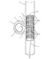
実施例1のステントは、図1に示すように、筒状であり、動脈瘤1の治療に用いられる。つまり、このステントは、動脈瘤1の開口部5を充分に覆うように血管3内に留置され、後述する挿通部11を挿通したカテーテル7から塞栓物質であるステンレス製のコイル9を動脈瘤1内に詰め込んで動脈瘤1を閉塞させる動脈瘤塞栓術に用いられる。Example 1
The stent of Example 1 is tubular, as shown in FIG. That is, this stent is indwelled in the
このステントは、図1及び図2に示すように、カテーテル7を挿通することができる複数個の挿通部11を有する筒状のステント本体10と、各挿通部11の夫々に設けられた弁体20とを備えている。ステント本体10と弁体20とは同素材で一体的に形成されている。ステントは合金製であり、弾性を有している。 This stent, as shown in FIGS. 1 and 2, includes a tubular stent
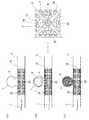
ステント本体10は、図2の展開図に示すように、縦方向(筒状における周方向)及び横方向(筒状における軸方向)に等間隔に離れて直線状に延びた連結帯13(図2において灰色に着色された部分)によって形成されている。そして、ステント本体10は、各連結帯13に囲まれて形成された正方形状の挿通部11が、縦方向(筒状における周方向)に4個、横方向(筒状における軸方向)に5個、連続的に並んで設けられている。挿通部11はカテーテル7を挿通することができる大きさを有している。 As shown in the developed view of FIG. 2, the
各挿通部11の夫々に設けられた弁体20は、図2及び図3に示すように、正方形状の挿通部11の各辺から内側に延び、挿通部11の各辺を一辺とし、挿通部11の中央部に位置する1つの頂点を有する二等辺三角形状である。ステントは1個の挿通部11に対して4枚の弁体20が設けられている。各挿通部11に設けられた4枚の弁体20の頂点から延びる斜辺は、隣り合う弁体20の斜辺との間に隙間21を形成している。このため、各挿通部11は対角線に沿ったX字状の隙間21が形成されている。隙間21は細く形成されており、挿通部11に大きな開口が形成されていない。 The
各弁体20は、挿通部11の各辺に沿って配置された4個の長方形状の開口22と、2種類の大きさで相似形の二等辺三角形状で形成された7個の開口23,24とから網目状に形成されている。つまり、各弁体20は大きさの相違する複数種類の相似形の網目状に形成されたフラクタル構造を有している。 Each
このように、このステントは、挿通部11を形成するステント本体10の連結帯13と弁体20との境界部が直線状に形成されている。このため、図1及び図4(B)に示すように、ステントの内側からカテーテル7の先端で弁体20の一部を外側へ押すと、境界部に形成された弁体20の一辺部が屈曲しつつ弁体20が湾曲して挿通部11が開き、挿通部11にカテーテル7を挿通させることができる。また、ステント本体10及び弁体20は、合金製であり、弾性を有しているため、挿通部11からカテーテル7を引き抜くと、弁体20は弾性力で筒状のステント本体10の外周面に沿った位置に復帰して、挿通部11が閉じる。 Thus, in this stent, the boundary between the
また、このステントは、正方形状の挿通部11の各辺を一辺とし、挿通部11の中央部に位置する1つの頂点を有する二等辺三角形状の弁体20が、2種類の大きさで相似形の二等辺三角形状の開口23,24によって網目状のフラクタル構造に形成されている。このため、各弁体20は、強度を有し、かつ弾性力を保持することができるため、このステントは、挿通部11からカテーテル7を引き抜くと各弁体20が筒状のステント本体10の外周面に沿った位置に確実に復帰し、挿通部11を確実に閉じることができる。 Further, in this stent, an isosceles
また、このステントは、ステント本体10と弁体20が同素材で一体的に形成されている。このため、ステント本体10から弁体20が剥離しない。また、ステント本体10に弁体20を取り付ける手間がない。また、ステントは、筒状のステント本体10と弁体20から形成される外周面に凹凸がないように形成されている。 Further, in the stent, the
このような構成を有するステントを用いた動脈瘤塞栓術について説明する。
先ず、図4(A)に示すように、動脈瘤1の開口部5を充分に覆うように血管3内にステントを留置する。この際、ステントは、外周面に凹凸がないため、血管壁を傷つけにくい。Aneurysm embolization using a stent having such a configuration will be described.
First, as shown in FIG. 4 (A), a stent is placed in the
次に、図4(B)に示すように、動脈瘤1の開口部5に向けて開口することができる挿通部11を選択し、その挿通部11に設けられた弁体20をカテーテル7の先端部で押し拡げて弁体20を開きながら動脈瘤1の内部に向けてカテーテル7の先端を突出させる。このステントは、ステント本体10の周壁部に複数個の挿通部11が連続して設けられているため、血管3内の留置する際にカテーテル7を挿通する挿通部11の向きを考慮する必要性に乏しい。つまり、複数の挿通部11から動脈瘤1の開口部5に向けて開口することができる挿通部11を選択してカテーテル7の先端を動脈瘤1の内部に向けて突出させることができる。 Next, as shown in FIG. 4B, the
したがって、実施例1のステントは動脈瘤1の内部に向けてカテーテル7を突出させることができる状態に血管3内へ容易に留置することができる。 Therefore, the stent of Example 1 can be easily deployed in the
そして、図4(C)に示すように、カテーテル7の先端開口からコイル9を動脈瘤1内に詰め込んで動脈瘤1を閉塞させる。その後、カテーテル7を挿通部11から引き抜く。すると、弁体20は弾性力で筒状のステント本体10の外周面に沿った位置に復帰して閉じる。このようにして、ステントを用いた動脈瘤塞栓術を終了する。 Then, as shown in FIG. 4 (C), the
このように、ステントは、ステント本体10の周壁部に複数個の挿通部11が設けられていても、カテーテル7を挿通した挿通部11以外の挿通部11は、弁体20によって閉じられている。また、カテーテル7を挿通した挿通部11も、コイル9を動脈瘤1内に詰め込んで閉塞した後、カテーテル7を引き抜くと、弁体20が閉じる。このため、このステントによって動脈瘤1内に詰め込んだコイル9が血管3内へ流出することを抑制することができる。 Thus, even if the stent has a plurality of
また、ステントの弁体20がフラクタル構造を有した網目状に形成されている。また、ステントは弁体20が閉じた状態で挿通部11に大きな開口が形成されていない。また、ステントは、外周面に凹凸がなく、血管壁に外周面が接触した状態で留置される。このため、施術後に血管3内に留置したステントが血管壁の細胞に早期に覆われるため、血栓の形成を早期に抑制することができる。また、弁体20がフラクタル構造を有しているため、弁体20が閉じた状態になると、血管3内から動脈瘤1内に流れ込む血液の流れに対する抵抗が大きくなり、動脈瘤1内に流れ込む血液の流入量を抑えることができる。 Further, the
本発明は上記記述及び図面によって説明した実施例1に限定されるものではなく、例えば次のような実施例も本発明の技術的範囲に含まれる。
(1)実施例1では、ステント本体に挿通部を連続的に設けたが、ステント本体に間隔を空けて挿通部を設けてもよい。この場合、ステント本体を網目状、特にフラクタル構造を有するように形成するとよい。
(2)実施例1では、ステント本体に挿通部を縦方向(筒状における周方向)に4個、横方向(筒状における軸方向)に5個、連続的に設けたが、より多くの挿通部を設けてもよい。
(3)実施例1では、ステント本体に正方形状の挿通部を形成したが、挿通部は他の形状であってもよい。この場合、弁体も二等辺三角形状でなく、挿通部に合わせた形状にすればよい。
(4)実施例1では、1個の挿通部に4枚の弁体を設けたが、弁体の枚数は適宜変更してもよい。
(5)実施例1では、弁体が二等辺三角形状のフラクタル構造を有していたが、他の形状のフラクタル構造であってもよい。また、弁体はフラクタル構造でない網目状に形成されていてもよい。
(6)実施例1では、ステント本体と弁体とを一体的に形成したが、ステント本体と弁体を別々に形成し、結合してもよい。The present invention is not limited to the first embodiment described above with reference to the drawings. For example, the following embodiments are also included in the technical scope of the present invention.
(1) In the first embodiment, the insertion portion is continuously provided in the stent body, but the insertion portion may be provided at intervals in the stent body. In this case, the stent body may be formed to have a mesh shape, in particular a fractal structure.
(2) In the first embodiment, four insertion portions in the longitudinal direction (the circumferential direction in the cylindrical shape) and five in the lateral direction (the axial direction in the cylindrical shape) are continuously provided in the stent body. An insertion portion may be provided.
(3) In Example 1, the square-shaped insertion part was formed in the stent body, but the insertion part may have another shape. In this case, the valve body may not be in the form of an isosceles triangle, but may be shaped according to the insertion portion.
(4) In the first embodiment, four valve bodies are provided in one insertion portion, but the number of valve bodies may be changed as appropriate.
(5) In Example 1, although the valve body had the fractal structure of the isosceles triangle shape, it may be a fractal structure of another shape. Moreover, the valve body may be formed in the mesh shape which is not a fractal structure.
(6) In the first embodiment, the stent body and the valve body are integrally formed, but the stent body and the valve body may be separately formed and coupled.
1…動脈瘤
7…カテーテル
9…コイル(塞栓物質)
10…ステント本体
11…挿通部
20…弁体1 ...
10 ...
Claims (6)
Translated fromJapanese周壁部に設けられ、カテーテルを挿通することができる複数個の正方形状の挿通部を有する筒状のステント本体と、
前記挿通部の夫々に設けられており、前記カテーテルが前記挿通部を挿通する際に開き、前記挿通部から前記カテーテルを引き抜くと閉じて前記動脈瘤内に詰め込んだ閉塞物質が血管内へ流出することを抑制する弁体と、
を備え、
前記弁体は、正方形状の前記挿通部の各辺から内側に延びており、
前記挿通部の各辺を1辺として、前記挿通部の中央部に位置する1つの頂点を有する二等辺三角形状をなしていることを特徴とするステント。A stent used to treat an aneurysm,
A cylindrical stent body provided on the peripheral wall portion and havinga plurality ofsquare-shaped insertion portions through which the catheter can be inserted;
Provided in each of the insertion parts, the catheter is opened when the insertion part is inserted, and is closed when the catheter is pulled out from the insertion part, so that the obstructed substance stuffed into the aneurysm flows out into the blood vessel. With a valve body to suppress
Equippedwith
The valve body extends inward from each side of the square insertion portion,
As one side of each side of the insertion portion, the stent characterized that youhave no a isosceles triangle having a vertex located at the center portion of the insertion portion.
Applications Claiming Priority (3)
| Application Number | Priority Date | Filing Date | Title |
|---|---|---|---|
| JP2014103330 | 2014-05-19 | ||
| JP2014103330 | 2014-05-19 | ||
| PCT/JP2015/063745WO2015178266A1 (en) | 2014-05-19 | 2015-05-13 | Stent |
Publications (2)
| Publication Number | Publication Date |
|---|---|
| JPWO2015178266A1 JPWO2015178266A1 (en) | 2017-04-20 |
| JP6534385B2true JP6534385B2 (en) | 2019-06-26 |
Family
ID=54553939
Family Applications (1)
| Application Number | Title | Priority Date | Filing Date |
|---|---|---|---|
| JP2016521056AActiveJP6534385B2 (en) | 2014-05-19 | 2015-05-13 | Stent |
Country Status (3)
| Country | Link |
|---|---|
| US (1) | US10398442B2 (en) |
| JP (1) | JP6534385B2 (en) |
| WO (1) | WO2015178266A1 (en) |
Families Citing this family (4)
| Publication number | Priority date | Publication date | Assignee | Title |
|---|---|---|---|---|
| WO2017004598A1 (en)* | 2015-07-02 | 2017-01-05 | Nsvascular, Inc. | Thin-film micromesh medical devices and related methods |
| CN105902291A (en)* | 2016-04-08 | 2016-08-31 | 张小曦 | Intracranial aneurysm interventional closure treatment device |
| CN107397616A (en)* | 2017-08-21 | 2017-11-28 | 北京赛铂医药科技有限公司 | The special auxiliary stand of aneurysm liquid embolizing agent |
| DE102023128476A1 (en)* | 2023-10-17 | 2025-04-17 | Christian-Albrechts-Universität zu Kiel, Körperschaft des öffentlichen Rechts | INTRASACULAR ANEURYSM IMPLANT |
Family Cites Families (18)
| Publication number | Priority date | Publication date | Assignee | Title |
|---|---|---|---|---|
| US6261257B1 (en)* | 1998-05-26 | 2001-07-17 | Renan P. Uflacker | Dialysis graft system with self-sealing access ports |
| US6514063B2 (en)* | 1999-01-07 | 2003-02-04 | International Business Machines Corporation | Tooling for forming a stent |
| JP2001238964A (en)* | 2000-02-29 | 2001-09-04 | Japan Lifeline Co Ltd | Stent |
| US6679264B1 (en)* | 2000-03-04 | 2004-01-20 | Emphasys Medical, Inc. | Methods and devices for use in performing pulmonary procedures |
| US6610031B1 (en)* | 2001-04-18 | 2003-08-26 | Origin Medsystems, Inc. | Valve assembly |
| CA2452953A1 (en) | 2001-07-18 | 2003-01-30 | The Research Foundation Of State University Of New York | Stent vascular intervention device and method |
| US7572288B2 (en)* | 2001-07-20 | 2009-08-11 | Microvention, Inc. | Aneurysm treatment device and method of use |
| JP2003250907A (en) | 2002-03-05 | 2003-09-09 | Terumo Corp | Stent |
| JP4057318B2 (en) | 2002-03-19 | 2008-03-05 | テルモ株式会社 | Stent |
| US20040199246A1 (en)* | 2003-04-02 | 2004-10-07 | Scimed Life Systems, Inc. | Expandable stent |
| US20110022149A1 (en)* | 2007-06-04 | 2011-01-27 | Cox Brian J | Methods and devices for treatment of vascular defects |
| EP2170220A2 (en)* | 2007-07-11 | 2010-04-07 | Itgi Medical Ltd. | Implantable graft-assembly |
| US9440058B2 (en)* | 2007-12-17 | 2016-09-13 | Cook Medical Technologies, LLC | Device for enabling repeated access to a vessel |
| US8470013B2 (en)* | 2008-10-20 | 2013-06-25 | Imds Corporation | Systems and methods for aneurysm treatment and vessel occlusion |
| MX2012005150A (en)* | 2009-11-03 | 2012-08-17 | Large Bore Closure L L C | Closure device. |
| DE102010035543A1 (en)* | 2010-08-26 | 2012-03-01 | Acandis Gmbh & Co. Kg | Medical device and system with such a device |
| US9393133B2 (en)* | 2011-02-18 | 2016-07-19 | Piolax Medical Devices, Inc. | Abdominal cavity-vein shunt stent |
| JP2015036107A (en) | 2013-08-16 | 2015-02-23 | 福田 敏男 | Intravascular treatment hybrid stent with similarity structure |
- 2015
- 2015-05-13JPJP2016521056Apatent/JP6534385B2/enactiveActive
- 2015-05-13USUS15/306,865patent/US10398442B2/ennot_activeExpired - Fee Related
- 2015-05-13WOPCT/JP2015/063745patent/WO2015178266A1/enactiveApplication Filing
Also Published As
| Publication number | Publication date |
|---|---|
| WO2015178266A1 (en) | 2015-11-26 |
| JPWO2015178266A1 (en) | 2017-04-20 |
| US20170049456A1 (en) | 2017-02-23 |
| US10398442B2 (en) | 2019-09-03 |
Similar Documents
| Publication | Publication Date | Title |
|---|---|---|
| JP7356471B2 (en) | Aneurysm treatment device and treatment method | |
| JP6534385B2 (en) | Stent | |
| ES2210133T3 (en) | STENT MATRIX | |
| ES2874198T3 (en) | An expansion ring for a braided 'stent' | |
| US10349944B2 (en) | Stent for connecting adjacent tissues and manufacturing method thereof | |
| EP1790297B1 (en) | Anastomosis device | |
| CN104042357B (en) | Braided Expansion Loop with Markers | |
| US20140114343A1 (en) | Stent for the coil embolization of a cerebral aneurysm | |
| KR101799713B1 (en) | Stent | |
| JP2017512574A (en) | Capture device having a capture structure comprising a tube section | |
| KR101772482B1 (en) | Anti-migration stent | |
| US20220346805A1 (en) | Patch deployment device | |
| JP2020124642A (en) | Stent | |
| JP6617994B2 (en) | Method for manufacturing medical stent with enhanced end resistance and stent | |
| US20150238334A1 (en) | Implant for Treating Aneurysms | |
| CN106539606A (en) | A kind of false chamber plugging device | |
| US9844653B2 (en) | Vascular occluder with crossing frame elements | |
| KR102453480B1 (en) | Stent for blood clots removal | |
| KR20160022597A (en) | Stent for cerebral aneurysm | |
| KR20160004766A (en) | Stent for cerebral aneurysm | |
| CN113349866A (en) | Plugging system and plugging support | |
| CN206777373U (en) | A kind of false chamber plugging device | |
| JP2005013302A (en) | Flexible stent gentle to blood vessel with excellent blood vessel follow-up property and inflatability | |
| JP2004275327A (en) | Stent with excellent vessel diameter retaining property and following property | |
| KR20120013814A (en) | Human lumen extension stent and stent insertion device comprising the same |
Legal Events
| Date | Code | Title | Description |
|---|---|---|---|
| A621 | Written request for application examination | Free format text:JAPANESE INTERMEDIATE CODE: A621 Effective date:20180226 | |
| A131 | Notification of reasons for refusal | Free format text:JAPANESE INTERMEDIATE CODE: A131 Effective date:20181016 | |
| A521 | Request for written amendment filed | Free format text:JAPANESE INTERMEDIATE CODE: A523 Effective date:20181207 | |
| TRDD | Decision of grant or rejection written | ||
| A01 | Written decision to grant a patent or to grant a registration (utility model) | Free format text:JAPANESE INTERMEDIATE CODE: A01 Effective date:20190523 | |
| A61 | First payment of annual fees (during grant procedure) | Free format text:JAPANESE INTERMEDIATE CODE: A61 Effective date:20190528 | |
| R150 | Certificate of patent or registration of utility model | Ref document number:6534385 Country of ref document:JP Free format text:JAPANESE INTERMEDIATE CODE: R150 | |
| R250 | Receipt of annual fees | Free format text:JAPANESE INTERMEDIATE CODE: R250 | |
| R250 | Receipt of annual fees | Free format text:JAPANESE INTERMEDIATE CODE: R250 | |
| R250 | Receipt of annual fees | Free format text:JAPANESE INTERMEDIATE CODE: R250 |