JP6534324B2 - Mirror holding mechanism - Google Patents
Mirror holding mechanismDownload PDFInfo
- Publication number
- JP6534324B2 JP6534324B2JP2015184631AJP2015184631AJP6534324B2JP 6534324 B2JP6534324 B2JP 6534324B2JP 2015184631 AJP2015184631 AJP 2015184631AJP 2015184631 AJP2015184631 AJP 2015184631AJP 6534324 B2JP6534324 B2JP 6534324B2
- Authority
- JP
- Japan
- Prior art keywords
- mirror
- reflection mirror
- shaft
- cam member
- reflection
- Prior art date
- Legal status (The legal status is an assumption and is not a legal conclusion. Google has not performed a legal analysis and makes no representation as to the accuracy of the status listed.)
- Active
Links
Images


Classifications
- G—PHYSICS
- G02—OPTICS
- G02B—OPTICAL ELEMENTS, SYSTEMS OR APPARATUS
- G02B7/00—Mountings, adjusting means, or light-tight connections, for optical elements
- G02B7/18—Mountings, adjusting means, or light-tight connections, for optical elements for prisms; for mirrors
- G02B7/182—Mountings, adjusting means, or light-tight connections, for optical elements for prisms; for mirrors for mirrors
- G02B7/1822—Mountings, adjusting means, or light-tight connections, for optical elements for prisms; for mirrors for mirrors comprising means for aligning the optical axis
- G02B7/1824—Manual alignment
- G—PHYSICS
- G02—OPTICS
- G02B—OPTICAL ELEMENTS, SYSTEMS OR APPARATUS
- G02B7/00—Mountings, adjusting means, or light-tight connections, for optical elements
- G02B7/18—Mountings, adjusting means, or light-tight connections, for optical elements for prisms; for mirrors
- G02B7/182—Mountings, adjusting means, or light-tight connections, for optical elements for prisms; for mirrors for mirrors
- G02B7/198—Mountings, adjusting means, or light-tight connections, for optical elements for prisms; for mirrors for mirrors with means for adjusting the mirror relative to its support
- G—PHYSICS
- G03—PHOTOGRAPHY; CINEMATOGRAPHY; ANALOGOUS TECHNIQUES USING WAVES OTHER THAN OPTICAL WAVES; ELECTROGRAPHY; HOLOGRAPHY
- G03B—APPARATUS OR ARRANGEMENTS FOR TAKING PHOTOGRAPHS OR FOR PROJECTING OR VIEWING THEM; APPARATUS OR ARRANGEMENTS EMPLOYING ANALOGOUS TECHNIQUES USING WAVES OTHER THAN OPTICAL WAVES; ACCESSORIES THEREFOR
- G03B21/00—Projectors or projection-type viewers; Accessories therefor
- G03B21/14—Details
- G03B21/142—Adjusting of projection optics
- G—PHYSICS
- G03—PHOTOGRAPHY; CINEMATOGRAPHY; ANALOGOUS TECHNIQUES USING WAVES OTHER THAN OPTICAL WAVES; ELECTROGRAPHY; HOLOGRAPHY
- G03B—APPARATUS OR ARRANGEMENTS FOR TAKING PHOTOGRAPHS OR FOR PROJECTING OR VIEWING THEM; APPARATUS OR ARRANGEMENTS EMPLOYING ANALOGOUS TECHNIQUES USING WAVES OTHER THAN OPTICAL WAVES; ACCESSORIES THEREFOR
- G03B21/00—Projectors or projection-type viewers; Accessories therefor
- G03B21/14—Details
- G03B21/28—Reflectors in projection beam
Landscapes
- Physics & Mathematics (AREA)
- General Physics & Mathematics (AREA)
- Optics & Photonics (AREA)
- Projection Apparatus (AREA)
- Mounting And Adjusting Of Optical Elements (AREA)
- Endoscopes (AREA)
Description
Translated fromJapanese本発明は、反射ミラーと、反射ミラーを保持するミラー保持部材とを備えるミラー保持機構に関する。 The present invention relates to a mirror holding mechanism including a reflection mirror and a mirror holding member holding the reflection mirror.
従来、曲面ミラーと、曲面ミラーを保持するミラー保持部材とを備える曲面ミラーの調整装置が知られている(たとえば、特許文献1参照)。特許文献1に記載の曲面ミラーの調整装置は、光軸に直交する第1軸線を回動軸として曲面ミラーを回動させることで曲面ミラーの角度調整を行う第1角度調整機構と、光軸と第1軸線とに直交する第2軸線を回動軸として曲面ミラーを回動させることで曲面ミラーの角度調整を行う第2角度調整機構と、第1軸線と平行な方向へ曲面ミラーを水平移動させることで曲面ミラーの位置調整を行う第1位置調整機構と、第2軸線と平行な方向へ曲面ミラーを平行移動させることで曲面ミラーの位置調整を行う第2位置調整機構とを備えている。また、この曲面ミラーの調整装置は、ミラー保持部材が固定される固定部材を備えている。 2. Description of the Related Art An adjusting device for a curved mirror including a curved mirror and a mirror holding member for holding the curved mirror is known (see, for example, Patent Document 1). The adjusting device for a curved mirror described in Patent Document 1 includes a first angle adjusting mechanism that adjusts the angle of the curved mirror by rotating the curved mirror by using the first axis perpendicular to the optical axis as a rotation axis, and an optical axis. And a second angle adjustment mechanism for adjusting the angle of the curved mirror by rotating the curved mirror with the second axis orthogonal to the first axis and the second axis as a rotation axis, and the curved mirror horizontally in the direction parallel to the first axis The first position adjustment mechanism that adjusts the position of the curved mirror by moving, and the second position adjustment mechanism that adjusts the position of the curved mirror by parallelly moving the curved mirror in the direction parallel to the second axis There is. Further, the adjusting device of the curved mirror includes a fixing member to which the mirror holding member is fixed.
特許文献1に記載の曲面ミラーの調整装置では、ミラー保持部材は、第1保持部材と第2保持部材とを備えており、第2位置調整機構は、第1保持部材と第2保持部材との間に配置されるワッシャおよび/または第2保持部材と固定部材との間に配置されるワッシャである。また、この調整装置では、第1軸線方向の両側において、第1保持部材と第2保持部材との間にワッシャが配置されるとともに、第2保持部材と固定部材との間にワッシャが配置されているため、第1軸線方向の一方に配置されるワッシャの厚さや枚数と、第1軸線方向の他方に配置されるワッシャの厚さや枚数とを変えることで、光軸を回動軸として曲面ミラーを回動させて曲面ミラーの角度調整を行うことも可能となっている。 In the curved mirror adjustment device described in Patent Document 1, the mirror holding member includes the first holding member and the second holding member, and the second position adjusting mechanism includes the first holding member and the second holding member. And / or a washer disposed between the second holding member and the fixing member. Further, in this adjustment device, the washer is disposed between the first holding member and the second holding member on both sides in the first axial direction, and the washer is disposed between the second holding member and the fixing member. Therefore, by changing the thickness and the number of washers arranged on one side in the first axial direction, and the thickness and the number of washers arranged on the other side in the first axial direction, a curved surface with the optical axis as the rotation axis It is also possible to rotate the mirror to adjust the angle of the curved mirror.
特許文献1に記載の曲面ミラーの調整装置では、第1保持部材と第2保持部材との間に配置されるワッシャや第2保持部材と固定部材との間に配置されるワッシャの厚さや枚数を変えることで、第2軸線方向における曲面ミラーの位置の調整や、光軸を回動軸とする曲面ミラーの角度の調整が行われているため、曲面ミラーの位置や角度を連続的に調整することができない。すなわち、この調整装置では、曲面ミラーの位置や角度の微調整が困難である。また、この調整装置では、曲面ミラーの位置や角度を調整する際に第2保持部材に対する第1保持部材の取外しおよび取付けを行ったり固定部材に対する第2保持部材の取外しおよび取付けを行ったりしてワッシャの取付けや取外しを行わなければならないため、曲面ミラーで反射されて投射面に投射される投射像を確認しながら、曲面ミラーの位置や角度を調整することは困難である。 In the curved mirror adjustment device described in Patent Document 1, the thickness or number of washers disposed between the first holding member and the second holding member, or between the second holding member and the fixing member Since the adjustment of the position of the curved mirror in the second axial direction and the adjustment of the angle of the curved mirror whose rotation axis is the optical axis are performed by changing, the position and the angle of the curved mirror are continuously adjusted. Can not do it. That is, in this adjustment device, it is difficult to finely adjust the position and angle of the curved mirror. Further, in this adjustment device, when adjusting the position and angle of the curved mirror, the first holding member is removed and attached to the second holding member, or the second holding member is removed and attached to the fixing member. It is difficult to adjust the position and the angle of the curved mirror while confirming the projection image reflected by the curved mirror and projected onto the projection surface, since the washer must be attached and removed.
そこで、本発明の課題は、反射ミラーの反射面で反射されて投射面に投射される投射像を確認しながら反射ミラーの位置や角度を微調整することが可能なミラー保持機構を提供することにある。 Therefore, an object of the present invention is to provide a mirror holding mechanism capable of finely adjusting the position and the angle of the reflection mirror while confirming the projection image reflected on the reflection surface of the reflection mirror and projected on the projection surface. It is in.
上記の課題を解決するため、本発明のミラー保持機構は、曲面状の反射面を有する反射ミラーと、反射ミラーを保持するミラー保持部材と、ミラー保持部材に回動可能に保持されるカム部材とを備え、反射ミラーの光軸に平行な方向を第1方向とし、第1方向に直交する方向を第2方向とし、第1方向と第2方向とに直交する方向を第3方向とすると、ミラー保持部材は、第2方向において反射ミラーを挟むように配置される2個の側面部を備え、2個の側面部の少なくとも一方には、反射ミラーから第2方向の外側へ突出する軸部が挿通されるガイド孔が側面部を貫通するように形成され、ガイド孔は、第2方向に直交する直交方向を長手方向とする長孔状に形成され、カム部材は、側面部よりも第2方向の外側に配置されるとともに側面部に回動可能に保持され、カム部材には、軸部の先端側部分が接触するカム面が形成され、カム部材が回動すると、軸部が直交方向へ移動することを特徴とする。 In order to solve the above problems, the mirror holding mechanism according to the present invention comprises a reflection mirror having a curved reflection surface, a mirror holding member for holding the reflection mirror, and a cam member rotatably held by the mirror holding member. , With the direction parallel to the optical axis of the reflecting mirror as the first direction, the direction orthogonal to the first direction as the second direction, and the direction orthogonal to the first direction and the second direction as the third direction. The mirror holding member includes two side portions arranged to sandwich the reflection mirror in the second direction, and at least one of the two side portions has an axis projecting outward in the second direction from the reflection mirror. The guide hole through which the portion is inserted is formed to penetrate the side surface portion, the guide hole is formed in a long hole shape having the longitudinal direction orthogonal to the second direction as the longitudinal direction, and the cam member is more than the side surface portion Placed outside in the second direction and A is rotatably held, the cam member is a cam surface distal portion of the shaft portion is in contact is formed, and when the cam member is rotated, characterized in that the shaft portion is moved in the perpendicular direction.
本発明のミラー保持機構では、ミラー保持部材の側面部に、反射ミラーから第2方向の外側へ突出する軸部が挿通されるガイド孔が側面部を貫通するように形成され、カム部材は、側面部よりも第2方向の外側に配置されるとともに側面部に回動可能に保持されている。また、本発明では、カム部材に、軸部の先端側部分が接触するカム面が形成され、カム部材が回動すると、第2方向に直交する直交方向へ軸部が移動する。そのため、本発明では、ミラー保持部材に反射ミラーを取り付けた状態でカム部材を回動させることで、軸部と一緒に反射ミラーを第2方向に直交する直交方向へ移動させて、ミラー保持部材に対する反射ミラーの位置や角度を連続的に調整することが可能になる。すなわち、本発明では、反射ミラーの位置や角度を調整する際にミラー保持部材に対する反射ミラーの取外しおよび取付けを行わなくても、反射ミラーの位置や角度を連続的に調整することが可能になる。したがって、本発明では、反射ミラーの反射面で反射されて投射面に投射される投射像を確認しながら反射ミラーの位置や角度を微調整することが可能になる。 In the mirror holding mechanism according to the present invention, a guide hole through which the shaft projecting from the reflection mirror in the second direction is inserted is formed in the side surface of the mirror holding member so as to penetrate the side surface. It is disposed outside the side surface in the second direction and is rotatably held by the side surface. Further, in the present invention, the cam member is formed with a cam surface in contact with the tip end side portion of the shaft portion, and when the cam member rotates, the shaft portion moves in the orthogonal direction orthogonal to the second direction. Therefore, in the present invention, by rotating the cam member in a state where the reflection mirror is attached to the mirror holding member, the reflection mirror is moved in the orthogonal direction orthogonal to the second direction together with the shaft portion. It is possible to continuously adjust the position and the angle of the reflecting mirror with respect to. That is, according to the present invention, when adjusting the position and angle of the reflection mirror, the position and angle of the reflection mirror can be continuously adjusted without removing and attaching the reflection mirror to the mirror holding member. . Therefore, in the present invention, it is possible to finely adjust the position and the angle of the reflection mirror while confirming the projection image reflected on the reflection surface of the reflection mirror and projected on the projection surface.
本発明において、直交方向は、たとえば、第3方向である。この場合には、ミラー保持部材に反射ミラーを取り付けた状態でカム部材を回動させることで、軸部と一緒に反射ミラーを第3方向へ移動させて、ミラー保持部材に対する反射ミラーの位置や角度を連続的に調整することが可能になる。また、本発明において、直交方向は、第1方向であっても良い。この場合には、ミラー保持部材に反射ミラーを取り付けた状態でカム部材を回動させることで、軸部と一緒に反射ミラーを第1方向へ移動させて、ミラー保持部材に対する反射ミラーの位置や角度を連続的に調整することが可能になる。 In the present invention, the orthogonal direction is, for example, the third direction. In this case, by rotating the cam member with the reflection mirror attached to the mirror holding member, the reflection mirror is moved in the third direction together with the shaft portion, and the position of the reflection mirror with respect to the mirror holding member It is possible to adjust the angle continuously. In the present invention, the orthogonal direction may be the first direction. In this case, by rotating the cam member with the reflection mirror attached to the mirror holding member, the reflection mirror is moved in the first direction together with the shaft portion, and the position of the reflection mirror with respect to the mirror holding member It is possible to adjust the angle continuously.
本発明において、カム部材は、第2方向を回動の軸方向とする回動が可能となるように側面部に保持されていることが好ましい。このように構成すると、第1方向または第3方向を回動の軸方向とする回動が可能となるようにカム部材が側面部に保持されている場合と比較して、第2方向においてミラー保持機構を小型化することが可能になる。 In the present invention, it is preferable that the cam member is held by the side surface portion so as to be able to rotate with the second direction as the axial direction of the rotation. With this configuration, the mirror in the second direction is compared with the case where the cam member is held by the side surface portion so that the first direction or the third direction can be turned to the axial direction of the rotation. It becomes possible to miniaturize the holding mechanism.
本発明において、たとえば、軸部は、反射ミラーから第2方向の両外側へ突出しており、2個の側面部にガイド孔が形成され、第2方向における2個の側面部の両外側のそれぞれにカム部材が配置されている。この場合には、たとえば、ミラー保持部材に対して第3方向への反射ミラーの位置調整を行うことが可能になるとともに、ミラー保持部材に対して第1方向を回動の軸方向とする反射ミラーの角度調整を行うことが可能になる。また、この場合には、たとえば、ミラー保持部材に対して第1方向への反射ミラーの位置調整を行うことが可能になるとともに、ミラー保持部材に対して第3方向を回動の軸方向とする反射ミラーの角度調整を行うことが可能になる。 In the present invention, for example, the shaft portion protrudes from the reflection mirror to both outer sides in the second direction, guide holes are formed in the two side portions, and both outer sides of the two side portions in the second direction The cam member is disposed on the In this case, for example, it becomes possible to adjust the position of the reflecting mirror in the third direction with respect to the mirror holding member, and the reflection in which the first direction is the axial direction of rotation with respect to the mirror holding member It becomes possible to adjust the angle of the mirror. Further, in this case, for example, it becomes possible to adjust the position of the reflecting mirror in the first direction with respect to the mirror holding member, and the third direction is the axial direction of rotation with respect to the mirror holding member. It is possible to adjust the angle of the reflecting mirror.
本発明において、ミラー保持機構は、軸部が形成されるとともに反射ミラーと別体で形成される軸部材を備え、直交方向は、第3方向であり、第2方向における反射ミラーの両端面のそれぞれには、第1方向を長手方向とするとともに第1方向の一端側が開口する係合溝が形成され、軸部材の一端側は、係合溝に係合し、軸部材の他端側は、軸部となっていることが好ましい。このように構成すると、第2方向における反射ミラーの両端側部分を軸部材に対して第1方向へ移動させることが可能になる。したがって、ガイド孔が第3方向を長手方向とする長孔状に形成されている場合であっても、ミラー保持部材に対して第1方向への反射ミラーの位置調整を行うことが可能になるとともに、ミラー保持部材に対して第3方向を回動の軸方向とする反射ミラーの角度調整を行うことが可能になる。 In the present invention, the mirror holding mechanism includes a shaft member in which the shaft portion is formed and is formed separately from the reflection mirror, and the orthogonal direction is the third direction, and both ends of the reflection mirror in the second direction. In each of them, an engagement groove is formed in which the first direction is the longitudinal direction and one end side in the first direction is open, one end side of the shaft member is engaged with the engagement groove, and the other end side of the shaft member is Preferably, it is an axial part. With this configuration, it is possible to move both end side portions of the reflection mirror in the second direction in the first direction with respect to the shaft member. Therefore, even when the guide hole is formed in the shape of a long hole whose longitudinal direction is the third direction, it is possible to adjust the position of the reflection mirror in the first direction with respect to the mirror holding member. At the same time, it is possible to adjust the angle of the reflection mirror whose axis direction of rotation is the third direction with respect to the mirror holding member.
本発明において、ミラー保持機構は、側面部にカム部材を固定するための固定用ボルトを備えることが好ましい。このように構成すると、反射ミラーの位置や角度が調整された後のカム部材のずれを防止することが可能になる。 In the present invention, the mirror holding mechanism preferably includes a fixing bolt for fixing the cam member to the side surface. With this configuration, it is possible to prevent the displacement of the cam member after the position and angle of the reflection mirror are adjusted.
本発明において、反射ミラーの、反射面の反対側の面の第2方向における両端側のそれぞれには、第1方向に直交する平面が形成されていることが好ましい。このように構成すると、所定の調整用治具を利用して第1方向へ平面を押すことで、ミラー保持部材に対して第1方向への反射ミラーの位置調整を行うことが可能になるとともに、ミラー保持部材に対して第3方向を回動の軸方向とする反射ミラーの角度調整を行うことが可能になる。 In the present invention, it is preferable that a plane orthogonal to the first direction is formed on each of both end sides in the second direction of the surface opposite to the reflection surface of the reflection mirror. With this configuration, it is possible to adjust the position of the reflection mirror in the first direction with respect to the mirror holding member by pushing the plane in the first direction using a predetermined adjustment jig. It is possible to adjust the angle of the reflection mirror whose axis direction of rotation is the third direction with respect to the mirror holding member.
本発明において、カム部材の外周面には、歯車が形成され、側面部には、歯車に噛み合う治具側歯車が外周面に形成される調整用治具の回動中心軸部を回動可能に支持する軸支持部が形成されていることが好ましい。このように構成すると、調整用治具の治具側歯車とカム部材の歯車とを容易かつ確実に噛み合わせることが可能になる。したがって、調整用治具を用いてカム部材を容易に回動させることが可能になり、その結果、ミラー保持部材に対する反射ミラーの位置や角度の調整を容易に行うことが可能になる。 In the present invention, a gear is formed on the outer peripheral surface of the cam member, and a jig side gear meshing with the gear is formed on the outer peripheral surface on the side surface portion. It is preferable that a shaft support portion for supporting the shaft is formed. With this configuration, the jig side gear of the adjustment jig and the gear of the cam member can be engaged easily and reliably. Therefore, it becomes possible to easily rotate the cam member using the adjustment jig, and as a result, it is possible to easily adjust the position and angle of the reflection mirror with respect to the mirror holding member.
以上のように、本発明のミラー保持機構では、反射ミラーの反射面で反射されて投射面に投射される投射像を確認しながら反射ミラーの位置や角度を微調整することが可能になる。 As described above, in the mirror holding mechanism of the present invention, it is possible to finely adjust the position and the angle of the reflection mirror while confirming the projection image reflected on the reflection surface of the reflection mirror and projected on the projection surface.
以下、図面を参照しながら、本発明の実施の形態を説明する。 Hereinafter, embodiments of the present invention will be described with reference to the drawings.
(投射光学系の概略構成)
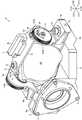
図1は、本発明の実施の形態にかかるミラー保持機構1を有する投射光学系4の斜視図である。図2は、図1に示す投射光学系4を異なる角度から示す斜視図である。(Schematic configuration of projection optical system)
FIG. 1 is a perspective view of a projection optical system 4 having a mirror holding mechanism 1 according to an embodiment of the present invention. FIG. 2 is a perspective view showing the projection optical system 4 shown in FIG. 1 from different angles.
本形態のミラー保持機構1は、曲面状の反射面2aを有する反射ミラー2と、反射ミラー2を保持するミラー保持部材としてのミラー保持枠3とを備えている。このミラー保持機構1は、投射光学系4の一部分を構成している。投射光学系4は、画像調整素子(図示省略)からの画像光を拡大してスクリーン等の投射面に投射するものである。この投射光学系4は、結像光学系を備えており、結像光学系は、複数のレンズによって構成されている。投射光学系4では、画像調整素子から射出され結像光学系を透過した画像光が反射面2aで反射されて、投射面に拡大投射される。この投射光学系4では、反射面2aを用いることで投射画角を広角化することが可能となっており、短い投射距離でも大きなサイズの投射画像を投射面へ投射することが可能となっている。 The mirror holding mechanism 1 of the present embodiment is provided with a
以下の説明では、反射ミラー2の光軸に平行な方向(図1等のZ方向)を「前後方向」とし、前後方向に直交する図1等のX方向を「左右方向」とし、前後方向と左右方向とに直交する図1等のY方向を「上下方向」とする。また、Z方向の一方であるZ1方向を「前方向」とし、Z方向の他方であるZ2方向を「後(後ろ)方向」とし、X方向の一方であるX1方向を「右方向」とし、X方向の他方であるX2方向を「左方向」とし、Y方向の一方であるY1方向を「上方向」とし、Y方向の他方であるY2方向を「下方向」とする。本形態の前後方向(Z方向)は第1方向であり、左右方向(X方向)は第2方向であり、上下方向(Y方向)は第3方向である。また、本形態の上下方向は、第2方向である左右方向に直交する直交方向である。 In the following description, a direction parallel to the optical axis of the reflection mirror 2 (Z direction in FIG. 1 etc.) is referred to as “front-back direction”, and an X direction in FIG. The Y direction in FIG. 1 etc. orthogonal to the left and right direction is referred to as “vertical direction”. Also, the Z1 direction that is one of the Z directions is "forward", the Z2 direction that is the other of the Z directions is "backward (backward)," and the X1 direction that is one of the X directions is "rightward." The X2 direction, which is the other in the X direction, is referred to as "left direction", the Y1 direction, which is one in the Y direction, is referred to as "upper direction", and the Y2 direction that is the other in the Y direction is referred to as "down direction". The longitudinal direction (Z direction) of this embodiment is a first direction, the lateral direction (X direction) is a second direction, and the vertical direction (Y direction) is a third direction. Moreover, the up-down direction of this form is an orthogonal direction orthogonal to the left-right direction which is a 2nd direction.
投射光学系4は、結像光学系を構成する複数のレンズが内周側に配置される鏡筒5と、ミラー保持枠3が固定されているとともに鏡筒5に固定される固定枠6とを備えている。複数のレンズのそれぞれは、レンズ枠に保持されており、レンズ枠は、前後方向への移動が可能となるように鏡筒5の内周側に配置されている。なお、図1、図2では、鏡筒5の後端側の一部分のみが図示されている。 The projection optical system 4 includes a
鏡筒5は、結像光学系の光軸が前後方向と平行になるように配置されている。また、鏡筒5は、結像光学系の光軸と反射ミラー2の光軸とがほぼ一致するように配置されている。画像調整素子は、鏡筒5よりも前側に配置されており、画像調整素子から射出された画像光は、後ろ側に向かって結像光学系を透過する。固定枠6は、ミラー保持枠3を保持する枠形状の部材であり、鏡筒5に固定される被固定部6aと、ミラー保持枠3が固定される固定部6bとを備えている。被固定部6aは、固定枠6の前側部分を構成し、固定部6bは、固定枠6の後ろ側分を構成している。被固定部6aは、ボルト7によって鏡筒5の後端側に固定されている。 The
(ミラー保持機構の構成)
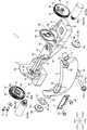
図3は、図1に示すミラー保持機構1の分解斜視図である。図4は、図1に示すミラー保持機構1を図3と異なる角度から示す分解斜視図である。図5は、図1に示すミラー保持機構1の縦断面図である。図6は、図1に示すミラー保持機構1の横断面図である。(Configuration of mirror holding mechanism)
FIG. 3 is an exploded perspective view of the mirror holding mechanism 1 shown in FIG. FIG. 4 is an exploded perspective view showing the mirror holding mechanism 1 shown in FIG. 1 from an angle different from FIG. FIG. 5 is a longitudinal sectional view of the mirror holding mechanism 1 shown in FIG. 6 is a cross-sectional view of the mirror holding mechanism 1 shown in FIG.
ミラー保持機構1は、上述の反射ミラー2およびミラー保持枠3に加え、ミラー保持枠3に回動可能に保持される2個のカム部材9と、一端側が反射ミラー2に係合するとともに他端側がミラー保持枠3およびカム部材9に係合する2個の軸部材10とを備えている。また、ミラー保持機構1は、反射ミラー2の上側部分を前側へ付勢する板バネ11と、反射ミラー2の下側部分を後ろ側へ付勢する圧縮コイルバネ12と、反射ミラー2の下側部分とミラー保持枠3の下側部分とを繋ぐボルト13とを備えている。 The mirror holding mechanism 1 includes, in addition to the
軸部材10は、反射ミラー2と別体で形成されている。この軸部材10は、鍔付きの円柱状に形成されており、軸部材10の一端側部分を構成する円柱状の軸部10aと、軸部材10の他端側部分を構成する円柱状の軸部10bと、軸部10aと軸部10bとの間に配置される円板状の鍔部10cとから構成されている。軸部10aの長さは軸部10bの長さよりも短くなっている。ボルト13は、たとえば、六角孔付ボルトであり、軸部13aと頭部13bとから構成されている。軸部13aの先端側には、オネジが形成されている。 The shaft member 10 is formed separately from the
反射ミラー2は、前面が凹曲面状となり後面が凸曲面状となる略曲板状に形成されており、反射ミラー2の前面に反射面2aが形成されている。すなわち、反射ミラー2には、凹曲面状の反射面2aが形成されている。反射ミラー2の上端の中心には、板バネ11が当接するバネ当接部2bが上側に向かって突出するように形成されている。反射ミラー2の下端の中心には、ボルト13が係合するボルト係合部2cが下側に向かって突出するように形成されている。 The
ボルト係合部2cには、前後方向に貫通する貫通孔2dが形成されている。すなわち、反射ミラー2の下側部分には、貫通孔2dが形成されている。貫通孔2dは、丸孔状に形成されている。貫通孔2dの内径は、ボルト13の軸部13aの外径よりも大きくなっている。また、図5に示すように、ボルト係合部2cの前面には、圧縮コイルバネ12の一部が配置される凹部2eが形成されている。凹部2eは、ボルト係合部2cの前面から後ろ側に向かって窪むように形成されている。また、凹部2eは、前後方向から見たときの内周面の形状が円形状となるように形成されている。この凹部2eは、貫通孔2dと同軸上に配置されている。 The
左右方向における反射ミラー2の両端面のそれぞれには、軸部材10の軸部10aが係合する係合溝2fが形成されている。係合溝2fは、係合溝2fの長手方向と前後方向とが一致するように形成されるとともに、左右方向の内側に向かって窪むように形成されている。また、係合溝2fの前端側は、開口しており、左右方向から見たときの係合溝2fの形状は、略U形状となっている。係合溝2fの上下方向の幅は、軸部10aの外径とほぼ等しくなっている。反射ミラー2の後面の左右方向の両端側のそれぞれには、前後方向に直交する平面2gが形成されている。本形態では、係合溝2fの後ろ側に平面2gが形成されており、係合溝2fと平面2gとは前後方向で重なるように形成されている。 In each of both end surfaces of the
ミラー保持枠3は、反射ミラー2を保持する枠形状の部材であり、左右方向において反射ミラー2を挟むように反射ミラー2の左右の両側のそれぞれに配置される2個の側面部3aと、固定枠6の固定部6bに載置されて固定される2個の被固定部3bと、2個の側面部3aを連結する連結部3c、連結部3dとを備えている。側面部3aは、略平板状に形成されており、側面部3aの厚さ方向と左右方向とが一致するように配置されている。2個の被固定部3bのそれぞれは、2個の側面部3aのそれぞれから左右方向の外側へ広がるように、2個の側面部3aのそれぞれの下端側に繋がっている。連結部3cは、略平板状に形成されており、連結部3cの厚さ方向と上下方向とが一致するように配置されている。この連結部3cは、2個の側面部3aの上端側かつ後端側を繋いでいる。連結部3dは、前後方向から見たときの形状が下側へ膨らむ略円弧状となるように形成されており、2個の側面部3aの下端側かつ前端側を繋いでいる。また、連結部3dは、側面部3aよりも下側へ突出している。 The
2個の側面部3aは、反射ミラー2の上側部分を左右方向で挟んでいる。側面部3aには、カム部材9を回動可能に支持する円柱状の支持軸3eと、カム部材9を固定するための円柱状の突起部3fと、軸部材10の軸部10bが挿通されるガイド孔3gと、後述の調整用治具30を支持する円筒状の軸支持部3hとが形成されている。支持軸3e、突起部3fおよび軸支持部3hは、2個の側面部3aのそれぞれの左右方向の外側の面から左右方向の外側へ突出するように形成されている。支持軸3eの先端側および突起部3fの先端側には、ネジ孔が形成されている。突起部3fは、支持軸3eの真上に配置されている。ガイド孔3gは、側面部3aを貫通するように形成されている。また、ガイド孔3gは、上下方向を長手方向とする長孔状に形成されている。ガイド孔3gの前後方向の幅は、軸部10bの外径とほぼ等しくなっている。このガイド孔3gは、支持軸3eの真下に配置されている。すなわち、突起部3fと支持軸3eとガイド孔3gは、上下方向において上側からこの順番で並ぶように形成されている。軸支持部3hは、ガイド孔3gよりも後ろ側に配置されている。 The two
被固定部3bには、上下方向に貫通する貫通孔3iが形成されている。被固定部3bは、固定枠6の固定部6bに載置された状態で貫通孔3iに挿通されるボルト15によって固定部6bに固定されている。また、被固定部3bには、固定枠6に対してミラー保持枠3の左右方向の位置を調整するためのネジ孔3jが形成されている。具体的には、2個の被固定部3bのそれぞれの左右方向の外側面から左右方向の内側に向かってネジ孔3jが形成されている。 A through
連結部3cの上面の中心には、板バネ11が固定されるバネ固定部3kが上側に向かって突出するように形成されている。バネ固定部3kには、反射ミラー2のバネ当接部2bが後ろ側から当接する当接部3mが形成されている(図5参照)。また、バネ固定部3kの後面側には、板バネ11が固定される平面状のバネ固定面3nが形成されている。バネ固定面3nは、当接部3mよりも後ろ側に配置されている。左右方向における連結部3cの両端側には、後述の調整用治具31を位置決めして固定するための円柱状の突起部3sが上側に向かって突出するように形成されている。突起部3sの先端側には、ネジ孔が形成されている。 At the center of the upper surface of the connecting
連結部3dの下端側には、ボルト13のオネジが係合するネジ孔3pと、圧縮コイルバネ12の一部が配置される凹部3rとが形成されている。凹部3rは、連結部3dの後面から前側に向かって窪むように形成されている。また、凹部3rは、前後方向から見たときの内周面の形状が円形状となるように形成されている。ネジ孔3pは、凹部3rの前側に形成されている。このネジ孔3pは、凹部3rと同軸上に配置されている。 At the lower end side of the connecting
カム部材9は、略円板状に形成されている。カム部材9の中心には、ミラー保持枠3の支持軸3eが挿入される挿入孔9aが形成されている。挿入孔9aは、カム部材9を貫通するように形成されている。カム部材9の外周面には、歯車9bが形成されている。歯車9bは、カム部材9の外周面の全周に亘って形成されている。カム部材9の一方の面には、軸部材10の軸部10bの先端側部分が係合するカム溝9cと、回動するカム部材9とミラー保持枠3の突起部3fとの干渉を防止するための逃げ溝9dとが形成されている。カム溝9cおよび逃げ溝9dは、カム部材9の一方の面から他方の面に向かって窪むように配置されている。 The
カム溝9cは、略半円弧状に形成されている。カム部材9の径方向におけるカム溝9cの外側面は、軸部10bの先端側部分が接触するカム面9eとなっている。カム面9eは、カム部材9の中心とカム面9eとの距離がカム部材9の周方向において連続的に変化する曲面状に形成されている。逃げ溝9dは、略半円弧状に形成されている。また、逃げ溝9dは、カム溝9cが形成されていない部分に形成されている。逃げ溝9dが形成された範囲には、カム部材9を貫通する円弧状の貫通孔9fが形成されている。 The
カム部材9は、側面部3aよりも左右方向の外側に配置されている。すなわち、2個のカム部材9のそれぞれは、左右方向における2個の側面部3aの両外側のそれぞれに配置されている。また、カム部材9は、カム溝9cおよび逃げ溝9dが形成される面が左右方向の内側を向くように配置されている。このカム部材9は、側面部3aに回動可能に保持されている。具体的には、カム部材9は、側面部3aの支持軸3eが挿入孔9aに挿入された状態で、左右方向におけるカム部材9の外側から支持軸3eのネジ孔に係合するボルト17によって側面部3aに取り付けられている。カム部材9は、支持軸3eに回動可能に支持されており、左右方向を回動の軸方向として回動する。カム部材9が側面部3aに保持された状態では、側面部3aの突起部3fが逃げ溝9dの中に配置されている。貫通孔9fには、左右方向におけるカム部材9の外側からボルト18が挿通されている。ボルト18の先端側は、突起部3fのネジ孔に係合している。ボルト18は、カム部材9を側面部3aに固定する機能を果たしている。本形態のボルト18は、側面部3aにカム部材9を固定するための固定用ボルトである。 The
上述のように、反射ミラー2は、2個の側面部3aの間に配置されている。この状態では、図6に示すように、軸部材10の軸部10aは、反射ミラー2の係合溝2fに係合している。また、軸部10bは、ガイド孔3gに挿通されるとともに、軸部10bの先端側部分は、カム溝9cに係合しており、カム面9eに接触している。そのため、カム部材9が回動すると、ガイド孔3gに沿って、軸部材10が上下方向へ連続的に移動するとともに、反射ミラー2の右端側および/または左端側が軸部材10と一緒に上下方向へ連続的に移動する。また、軸部10bは、ガイド孔3gに挿通されるとともに、軸部10bの先端側部分は、カム溝9cに係合しており、軸部10bは、反射ミラー2から左右方向の外側へ突出している。具体的には、2個の軸部10bのそれぞれが、反射ミラー2から左右方向の両外側へ突出している。右側に配置される軸部材10の鍔部10cと右側に配置される側面部3aとの間には、波座金21が配置されている。波座金21の内周側には、軸部10bが挿通されている。波座金21は、左側に配置される側面部3aに向かって、反射ミラー2および2個の軸部材10を付勢している。 As described above, the
また、反射ミラー2が2個の側面部3aの間に配置された状態では、反射ミラー2のバネ当接部2bがミラー保持枠3のバネ固定部3kよりも後ろ側に配置され、反射ミラー2のボルト係合部2cがミラー保持枠3の連結部3dの下端側部分よりも後ろ側に配置されている。板バネ11は、ボルト22によってバネ固定部3kのバネ固定面3nに固定されており、バネ当接部2bが当接部3mに後ろ側から当接するようにバネ当接部2bを付勢している。 Further, in a state where the
また、図5に示すように、圧縮コイルバネ12の前端側は、ミラー保持枠3の凹部3rの中に配置され、圧縮コイルバネ12の後端側は、反射ミラー2の凹部2eの中に配置されている。ボルト13の頭部13bは、ボルト係合部2cよりも後ろ側に配置され、軸部13aは、貫通孔2dおよび圧縮コイルバネ12の内周側に挿通されている。また、軸部13aに形成されるオネジは、連結部3dのネジ孔3pに係合している。圧縮コイルバネ12は、ボルト係合部2cと連結部3dの下側部分とが互いに離れるように、かつ、ボルト係合部2cが頭部13bに接触するようにボルト係合部2cを付勢している。そのため、反射ミラー2の下側部分は、ミラー保持枠3の下側部分に対して動かないようにミラー保持枠3の下側部分に保持される。 Further, as shown in FIG. 5, the front end side of the
(反射ミラーの調整方法)
図7は、図1に示す投射光学系4において反射ミラー2の調整が行われるときの状態を説明するための斜視図である。(How to adjust the reflection mirror)
FIG. 7 is a perspective view for explaining a state in which the
投射光学系4では、以下のように反射ミラー2の角度および位置を調整する。すなわち、鏡筒5に対する固定枠6の前後方向の取付位置を調整することで、前後方向における反射ミラー2の位置を調整する。具体的には、ボルト7を取り外した状態で、あるいは、ボルト7を緩めた状態で、固定枠6の被固定部6aと鏡筒5との間に配置される座金(図示省略)の厚さや枚数を変えて鏡筒5に対する固定枠6の前後方向の取付位置を調整することで、前後方向における反射ミラー2の位置を調整する。前後方向における反射ミラー2の位置の調整が終わると、ボルト7を締め込んで鏡筒5に被固定部6aを固定する。 The projection optical system 4 adjusts the angle and position of the
また、固定枠6に対するミラー保持枠3の左右方向の取付位置を調整することで、左右方向における反射ミラー2の位置を調整する。具体的には、ボルト15を緩めた状態で、調整用ボルト(図示省略)の先端が固定枠6に接触するように左右方向の外側からミラー保持枠3のネジ孔3jに調整用ボルトを係合させるとともに、ネジ孔3jに対する調整用ボルトのねじ込み量を調整して固定枠6に対するミラー保持枠3の左右方向の取付位置を調整することで、左右方向における反射ミラー2の位置を調整する。左右方向における反射ミラー2の位置の調整が終わると、ボルト15を締め込んで固定枠6にミラー保持枠3を固定する。なお、左右方向における反射ミラー2の位置調整後に、ネジ孔3jから調整用ボルトを取り外しても良い。 Further, the position of the
さらに、ボルト18を取り外した状態で、あるいは、ボルト18を緩めた状態で、2個のカム部材9を同じ方向へ同じ角度回動させて、ミラー保持枠3に対して反射ミラー2の左右の両側を同じ量昇降させることで、上下方向における反射ミラー2の位置を調整する。また、ボルト18を取り外した状態で、あるいは、ボルト18を緩めた状態で、1個のカム部材9を回動させて、または、2個のカム部材9を異なる方向へ回動させて、あるいは、2個のカム部材9を同じ方向へ異なる角度回動させて、ミラー保持枠3に対して反射ミラー2の左右の両側を異なる量昇降させることで、前後方向を回動の軸方向とする反射ミラー2の角度を調整する。上下方向における反射ミラー2の位置の調整や前後方向を回動の軸方向とする反射ミラー2の角度の調整が終わると、突起部3fのネジ孔にボルト18を締め込んでカム部材9を側面部3aに固定する。 Furthermore, with the
なお、上下方向における反射ミラー2の位置の調整や前後方向を回動の軸方向とする反射ミラー2の角度の調整は、ミラー保持枠3が固定枠6に固定され、固定枠6が鏡筒5に固定されるとともに、板バネ11、圧縮コイルバネ12およびボルト13、22によってミラー保持枠3に反射ミラー2が取り付けられた状態で行われる。上述のように、反射ミラー2の貫通孔2dの内径がボルト13の軸部13aの外径よりも大きくなっているため、ボルト13が取り付けられた状態でも、上下方向における反射ミラー2の位置の調整や前後方向を回動の軸方向とする反射ミラー2の角度の調整を行うことが可能となっている。また、波座金21が変形するため、前後方向を回動の軸方向とする反射ミラー2の角度の調整が可能となっている。 In the adjustment of the position of the
本形態では、調整用治具30を用いて、上下方向における反射ミラー2の位置や前後方向を回動の軸方向とする反射ミラー2の角度を調整する。調整用治具30は、円柱状に形成される把持部30aと、カム部材9の歯車9bに噛み合う治具側歯車30bが外周面に形成される歯車部30cと、側面部3aの軸支持部3hに回動可能に支持される円柱状の回動中心軸部30dとから構成されている。把持部30aと歯車部30cと回動中心軸部30dとは、調整用治具30の軸方向においてこの順番で配置されている。上下方向における反射ミラー2の位置や前後方向を回動の軸方向とする反射ミラー2の角度を調整するときには、歯車9bと治具側歯車30bとが噛み合うように回動中心軸部30dを軸支持部3hに挿入してから、把持部30aを掴んで調整用治具30を回動させる。調整用治具30が回動すると、カム部材9も一緒に回動して、上下方向における反射ミラー2の位置や前後方向を回動の軸方向とする反射ミラー2の角度が調整される。また、調整が終わると、調整用治具30は取り外される。 In this embodiment, the adjustment jig 30 is used to adjust the position of the
さらにまた、反射ミラー2の平面2gを押すことで、上下方向を回動の軸方向とする反射ミラー2の角度を調整する。本形態では、調整用治具31を用いて、上下方向を回動の軸方向とする反射ミラー2の角度を調整する。調整用治具31は、治具本体部32と、治具本体部32をミラー保持枠3に固定するための2本の固定用ボルト33と、反射ミラー2の角度を調整する2本の調整用ボルト34とを備えている。固定用ボルト33は、把持部33aと、把持部33aから突出する軸部(図示省略)とを備えており、軸部にオネジが形成されている。調整用ボルト34は、把持部34aと、把持部34aから突出する軸部34bとを備えており、軸部34bにオネジが形成されている。軸部34bの先端は、平面状となっている(図6参照)。 Furthermore, by pressing the
治具本体部32は、ミラー保持枠3の連結部3cに載置されて固定される平板状の被固定部32aと、調整用ボルト34を保持する2個のボルト保持部32bとから構成されている。被固定部32aの左右の両端側には、固定用ボルト33の軸部が挿通される貫通孔(図示省略)が形成されている。ボルト保持部32bは、前後方向に直交する平板状に形成されている。2個のボルト保持部32bのそれぞれは、被固定部32aの左右の両端側のそれぞれに繋がるように、かつ、被固定部32aの左右の両端側のそれぞれから90°に折れ曲がるように形成されている。ボルト保持部32bには、調整用ボルト34の軸部34bのオネジが係合するネジ孔32cが形成されている(図6参照)。 The jig main body 32 includes a flat plate-like fixed portion 32 a which is mounted and fixed on the connecting
調整用治具31は、連結部3cに被固定部32aが載置されるとともに固定用ボルト33のオネジが突起部3sのネジ孔にねじ込まれることで、ミラー保持枠3に取り付けられる。治具本体部32に取り付けられた2本の調整用ボルト34の軸部34bの先端のそれぞれは、反射ミラー2の2個の平面2gのそれぞれに後ろ側から当接可能な位置に配置されており、ネジ孔32cに対する調整用ボルト34のねじ込み量を調整して2個の平面2gの押し量を調整することで、上下方向を回動の軸方向とする反射ミラー2の角度を調整する。上下方向を回動の軸方向とする反射ミラー2の角度の調整が終わると、調整用治具31は、ミラー保持枠3から取り外される。 The
なお、上下方向を回動の軸方向とする反射ミラー2の角度の調整も、ミラー保持枠3が固定枠6に固定され、固定枠6が鏡筒5に固定されるとともに、板バネ11、圧縮コイルバネ12およびボルト13、22によってミラー保持枠3に反射ミラー2が取り付けられた状態で行われる。上述のように、反射ミラー2の貫通孔2dの内径がボルト13の軸部13aの外径よりも大きくなっているため、ボルト13が取り付けられた状態でも、上下方向を回動の軸方向とする反射ミラー2の角度の調整を行うことが可能となっている。また、軸部材10の軸部10aが係合する反射ミラー2の係合溝2fが前後方向を長手方向とする溝状に形成されているため、上下方向を回動の軸方向とする反射ミラー2の角度の調整を行うことが可能となっている。 In the adjustment of the angle of the
また、ミラー保持枠3のネジ孔3pに対するボルト13のねじ込み量を調整することで、左右方向を回動の軸方向とする反射ミラー2の角度を調整する。なお、左右方向を回動の軸方向とする反射ミラー2の角度の調整もミラー保持枠3が固定枠6に固定され、固定枠6が鏡筒5に固定されるとともに、板バネ11、圧縮コイルバネ12およびボルト13、22によってミラー保持枠3に反射ミラー2が取り付けられた状態で行われる。 Further, by adjusting the screwing amount of the bolt 13 with respect to the
(本形態の主な効果)
以上説明したように、本形態では、ミラー保持枠3が固定枠6に固定され、固定枠6が鏡筒5に固定されるとともに、板バネ11、圧縮コイルバネ12およびボルト13、22を用いてミラー保持枠3に反射ミラー2が取り付けられた状態でカム部材9を回動させることで、上下方向における反射ミラー2の位置や前後方向を回動の軸方向とする反射ミラー2の角度が連続的に調整されている。そのため、本形態では、反射ミラー2の反射面2aで反射されて投射面に投射される投射像を確認しながら、上下方向における反射ミラー2の位置や前後方向を回動の軸方向とする反射ミラー2の角度を微調整することが可能になる。(Main effects of this form)
As described above, in the present embodiment, the
また、本形態では、ミラー保持枠3が固定枠6に固定され、固定枠6が鏡筒5に固定されるとともに、板バネ11、圧縮コイルバネ12およびボルト13、22を用いてミラー保持枠3に反射ミラー2が取り付けられた状態で治具本体部32のネジ孔32cに対する調整用ボルト34のねじ込み量を調整することで上下方向を回動の軸方向とする反射ミラー2の角度が調整されている。そのため、本形態では、反射ミラー2の反射面2aで反射されて投射面に投射される投射像を確認しながら、上下方向を回動の軸方向とする反射ミラー2の角度を微調整することが可能になる。 Further, in the present embodiment, the
さらに、本形態では、ミラー保持枠3が固定枠6に固定され、固定枠6が鏡筒5に固定されるとともに、板バネ11、圧縮コイルバネ12およびボルト13、22を用いてミラー保持枠3に反射ミラー2が取り付けられた状態でミラー保持枠3のネジ孔3pに対するボルト13のねじ込み量を調整することで、左右方向を回動の軸方向とする反射ミラー2の角度が調整されている。そのため、本形態では、反射ミラー2の反射面2aで反射されて投射面に投射される投射像を確認しながら、左右方向を回動の軸方向とする反射ミラー2の角度を微調整することが可能になる。 Furthermore, in the present embodiment, the
また、本形態では、板バネ11、圧縮コイルバネ12およびボルト13、22によってミラー保持枠3に反射ミラー2が取り付けられた状態で、上下方向における反射ミラー2の位置の調整、前後方向を回動の軸方向とする反射ミラー2の角度の調整および上下方向を回動の軸方向とする反射ミラー2の角度の調整が行われるため、調整後の反射ミラー2がミラー保持枠3に対してずれるのを防止することが可能になる。 Further, in the present embodiment, with the
本形態では、カム部材9は、左右方向を回動の軸方向とする回動が可能となるように側面部3aに保持されている。そのため、本形態では、前後方向または上下方向を回動の軸方向とする回動が可能となるようにカム部材9が側面部3aに保持されている場合と比較して、左右方向においてミラー保持機構1を小型化することが可能になる。また、本形態では、ボルト18によってカム部材9が側面部3aに固定されているため、上下方向における反射ミラー2の位置や前後方向を回動の軸方向とする反射ミラー2の角度が調整された後のカム部材9のずれを防止することが可能になる。 In the present embodiment, the
本形態では、側面部3aに軸支持部3hが形成されている。そのため、本形態では、調整用治具30の治具側歯車30bとカム部材9の歯車9bとを容易かつ確実に噛み合わせることが可能になる。したがって、本形態では、調整用治具30を用いてカム部材9を容易に回動させることが可能になり、その結果、上下方向における反射ミラー2の位置の調整や前後方向を回動の軸方向とする反射ミラー2の角度の調整が容易になる。また、本形態では、調整用治具30を用いてカム部材9を回動させているため、歯車9bと治具側歯車30bとのギア比を大きくすることで、カム部材9の回動角度が小さくても精度良くカム部材9を回動させることが可能になる。したがって、本形態では、歯車9bと治具側歯車30bとのギア比を大きくすることで、上下方向における反射ミラー2の位置の調整や前後方向を回動の軸方向とする反射ミラー2の角度の調整をより精度良く行うことが可能になる。 In the present embodiment, the
(他の実施の形態)
上述した形態では、上下方向における反射ミラー2の位置や前後方向を回動の軸方向とする反射ミラー2の角度を調整する際に、調整用治具30を用いてカム部材9を回転させているが、カム部材9を直接掴んでカム部材9を回動させても良い。この場合には、カム部材9の外周面に歯車9bが形成されていなくても良い。また、この場合には、側面部3aに軸支持部3hが形成されていなくても良い。また、上述した形態では、鏡筒5に対する固定枠6の前後方向の取付位置を調整することで、前後方向における反射ミラー2の位置を調整しているが、調整用治具31の2本の調整用ボルト34によって反射ミラー2の2箇所に形成される平面2gを同じ量押すことで、前後方向における反射ミラー2の位置を調整しても良い。すなわち、調整用治具31を用いて、ミラー保持枠3に対して反射ミラー2を前後方向に移動させることで前後方向における反射ミラー2の位置を調整しても良い。(Other embodiments)
In the embodiment described above, the adjustment jig 30 is used to rotate the
上述した形態では、反射ミラー2から左右方向の両外側へ突出する2個の軸部10bのそれぞれが上下方向に移動可能となっているが、反射ミラー2から左右方向の一方へ突出する1個の軸部10bのみが上下方向へ移動可能となっていても良い。たとえば、反射ミラー2から左右方向の一方へ突出する軸部10bがガイド孔3gに挿通され、かつ、カム溝9cに係合するとともに、反射ミラー2から左右方向の他方へ突出する軸部10bがミラー保持枠3に形成される丸孔状の支持孔に挿通されて支持されても良い。この場合には、左右方向の他方に配置される側面部3aにガイド孔3gは形成されない。また、左右方向の他方にカム部材9は配置されない。 In the embodiment described above, each of the two
上述した形態では、軸部材10は反射ミラー2と別体で形成されているが、反射ミラー2から左右方向の両外側へ突出する軸部10bが反射ミラー2と一体で形成されても良い。また、上述した形態では、バネ当接部2bや係合溝2fといった突起部や溝が反射ミラー2に直接、形成されているが、反射ミラー2の外周側に反射ミラー2と一体となるように所定の枠部材が固定されるとともに、この枠部材にバネ当接部2bや係合溝2fに相当する突起部や溝が形成されても良い。また、上述した形態では、カム部材9は、左右方向を回動の軸方向として回動するが、カム部材9は、前後方向または上下方向を回動の軸方向として回動しても良い。なお、上述した形態において、カム部材9の初期位置がわかるように、側面部3aおよびカム部材9に所定の目印を設けても良い。 In the embodiment described above, the shaft member 10 is formed separately from the
上述した形態では、カム部材9を回動させることで、上下方向における反射ミラー2の位置や前後方向を回動の軸方向とする反射ミラー2の角度が連続的に調整されているが、カム部材9を回動させることで、前後方向における反射ミラー2の位置や上下方向を回動の軸方向とする反射ミラー2の角度が連続的に調整されても良い。この場合には、ガイド孔3gは、前後方向を長手方向とする長孔状に形成され、カム面9eは、軸部材10が前後方向へ移動するように所定の形状に形成される。また、この場合には、係合溝2fは、たとえば、係合溝2fの長手方向と上下方向とが一致するように、かつ、係合溝2fの上下の一端が開口するように形成される。あるいは、係合溝2fに代えて、軸部材10の軸部10aが挿入される円形状の凹部が形成される。また、カム部材9を回動させることで、左右方向に直交するとともに前後方向および上下方向に対して傾斜する方向における反射ミラー2の位置や、この方向と左右方向とに直交する方向を回動の軸方向とする反射ミラー2の角度が連続的に調整されても良い。この場合には、このような調整が可能となるように、ガイド孔3g、カム面9eおよび係合溝2fが形成されれば良い。 In the embodiment described above, by rotating the
1 ミラー保持機構
2 反射ミラー
2a 反射面
2f 係合溝
2g 平面
3 ミラー保持枠(ミラー保持部材)
3a 側面部
3g ガイド孔
3h 軸支持部
9 カム部材
9b 歯車
9e カム面
10 軸部材
10b 軸部
18 ボルト(固定用ボルト)
30 調整用治具
30b 治具側歯車
30d 回動中心軸部
X 第2方向
Y 第3方向(直交方向)
Z 第1方向1
30 Jig for
Z first direction
Claims (9)
Translated fromJapanese前記反射ミラーの光軸に平行な方向を第1方向とし、前記第1方向に直交する方向を第2方向とし、前記第1方向と前記第2方向とに直交する方向を第3方向とすると、
前記ミラー保持部材は、前記第2方向において前記反射ミラーを挟むように配置される2個の側面部を備え、
2個の前記側面部の少なくとも一方には、前記反射ミラーから前記第2方向の外側へ突出する軸部が挿通されるガイド孔が前記側面部を貫通するように形成され、
前記ガイド孔は、前記第2方向に直交する直交方向を長手方向とする長孔状に形成され、
前記カム部材は、前記側面部よりも前記第2方向の外側に配置されるとともに前記側面部に回動可能に保持され、
前記カム部材には、前記軸部の先端側部分が接触するカム面が形成され、
前記カム部材が回動すると、前記軸部が前記直交方向へ移動することを特徴とするミラー保持機構。A reflection mirror having a curved reflection surface, a mirror holding member for holding the reflection mirror, and a cam member rotatably held by the mirror holding member;
A direction parallel to the optical axis of the reflection mirror is a first direction, a direction orthogonal to the first direction is a second direction, and a direction orthogonal to the first direction and the second direction is a third direction. ,
The mirror holding member includes two side portions arranged to sandwich the reflection mirror in the second direction,
At least one of the two side surfaces is formed with a guide hole through which the shaft projecting from the reflection mirror to the outside in the second direction is inserted.
The guide hole is formed in the shape of a long hole whose longitudinal direction is orthogonal to the second direction, and
The cam member is disposed on the outer side in the second direction than the side surface portion and is rotatably held by the side surface portion.
The cam member is formed with a cam surface with which the tip end side portion of the shaft portion contacts.
A mirror holding mechanism characterized in that, when the cam member rotates, the shaft moves in the orthogonal direction.
2個の前記側面部に前記ガイド孔が形成され、
前記第2方向における2個の前記側面部の両外側のそれぞれに前記カム部材が配置されていることを特徴とする請求項1から4のいずれかに記載のミラー保持機構。The shaft projects from the reflection mirror to the outer side in the second direction,
The guide holes are formed in the two side surfaces,
The mirror holding mechanism according to any one of claims 1 to 4, wherein the cam member is disposed on each of both outer sides of the two side surface portions in the second direction.
前記直交方向は、前記第3方向であり、
前記第2方向における前記反射ミラーの両端面のそれぞれには、前記第1方向を長手方向とするとともに前記第1方向の一端側が開口する係合溝が形成され、
前記軸部材の一端側は、前記係合溝に係合し、
前記軸部材の他端側は、前記軸部となっていることを特徴とする請求項5記載のミラー保持機構。And a shaft member which is formed separately from the reflection mirror while the shaft portion is formed,
The orthogonal direction is the third direction,
In each of both end surfaces of the reflection mirror in the second direction, an engagement groove is formed in which the first direction is a longitudinal direction and one end side of the first direction is opened,
One end side of the shaft member engages with the engagement groove,
The mirror holding mechanism according to claim 5, wherein the other end side of the shaft member is the shaft portion.
前記側面部には、前記歯車に噛み合う治具側歯車が外周面に形成される調整用治具の回動中心軸部を回動可能に支持する軸支持部が形成されていることを特徴とする請求項1から8のいずれかに記載のミラー保持機構。A gear is formed on the outer peripheral surface of the cam member,
The side surface portion is characterized in that a shaft support portion for rotatably supporting a rotation center shaft portion of an adjustment jig in which a jig side gear meshing with the gear is formed on an outer peripheral surface is formed. The mirror holding mechanism according to any one of claims 1 to 8.
Priority Applications (5)
| Application Number | Priority Date | Filing Date | Title |
|---|---|---|---|
| JP2015184631AJP6534324B2 (en) | 2015-09-18 | 2015-09-18 | Mirror holding mechanism |
| EP16846067.3AEP3351984B1 (en) | 2015-09-18 | 2016-06-28 | Mirror holding mechanism |
| US15/757,860US10466439B2 (en) | 2015-09-18 | 2016-06-28 | Mirror holding mechanism |
| CN201680051778.2ACN107949799B (en) | 2015-09-18 | 2016-06-28 | Mirror holding mechanism |
| PCT/JP2016/069063WO2017047194A1 (en) | 2015-09-18 | 2016-06-28 | Mirror holding mechanism |
Applications Claiming Priority (1)
| Application Number | Priority Date | Filing Date | Title |
|---|---|---|---|
| JP2015184631AJP6534324B2 (en) | 2015-09-18 | 2015-09-18 | Mirror holding mechanism |
Publications (2)
| Publication Number | Publication Date |
|---|---|
| JP2017058565A JP2017058565A (en) | 2017-03-23 |
| JP6534324B2true JP6534324B2 (en) | 2019-06-26 |
Family
ID=58288702
Family Applications (1)
| Application Number | Title | Priority Date | Filing Date |
|---|---|---|---|
| JP2015184631AActiveJP6534324B2 (en) | 2015-09-18 | 2015-09-18 | Mirror holding mechanism |
Country Status (5)
| Country | Link |
|---|---|
| US (1) | US10466439B2 (en) |
| EP (1) | EP3351984B1 (en) |
| JP (1) | JP6534324B2 (en) |
| CN (1) | CN107949799B (en) |
| WO (1) | WO2017047194A1 (en) |
Families Citing this family (6)
| Publication number | Priority date | Publication date | Assignee | Title |
|---|---|---|---|---|
| CN106990662B (en)* | 2017-05-15 | 2019-03-05 | 海信集团有限公司 | A kind of regulating mechanism of projector's mean camber reflecting mirror and projector |
| CN109634033A (en)* | 2018-11-30 | 2019-04-16 | 苏州佳世达光电有限公司 | Imaging device |
| WO2021106755A1 (en)* | 2019-11-27 | 2021-06-03 | アルプスアルパイン株式会社 | Reflector driving device |
| CN111552054B (en)* | 2020-06-09 | 2021-12-28 | 河南平原光电有限公司 | Off-axis three-mirror optical system assembling and adjusting method |
| US11852805B2 (en) | 2021-01-05 | 2023-12-26 | Raytheon Company | Wave scanning optic |
| CN114137689B (en)* | 2021-11-03 | 2023-06-20 | 中航洛阳光电技术有限公司 | Mirror mechanism capable of accurately and continuously adjusting angle |
Family Cites Families (13)
| Publication number | Priority date | Publication date | Assignee | Title |
|---|---|---|---|---|
| JP4717529B2 (en)* | 2005-06-28 | 2011-07-06 | キヤノン株式会社 | Optical system tilt drive mechanism |
| JP4720852B2 (en)* | 2008-05-14 | 2011-07-13 | ソニー株式会社 | Mirror drive device and imaging device |
| JP3150083U (en)* | 2009-01-30 | 2009-04-30 | 株式会社テクノルート | Blind spot elimination side mirror |
| JPWO2013080625A1 (en)* | 2011-11-30 | 2015-04-27 | パナソニックIpマネジメント株式会社 | Mirror actuator, beam irradiation device and laser radar |
| JP6120137B2 (en)* | 2013-01-17 | 2017-04-26 | 株式会社nittoh | Curved mirror adjustment device |
| JP6165451B2 (en)* | 2013-01-29 | 2017-07-19 | 株式会社nittoh | Optical member |
| JP6200222B2 (en)* | 2013-06-26 | 2017-09-20 | 株式会社nittoh | Projector device |
| JP6160312B2 (en)* | 2013-07-05 | 2017-07-12 | リコーイメージング株式会社 | Camera movable mirror drive device and camera |
| JP6335681B2 (en)* | 2014-06-25 | 2018-05-30 | キヤノン株式会社 | Imaging device |
| US10393995B2 (en)* | 2014-08-22 | 2019-08-27 | Canon Kabushiki Kaisha | Mirror driving device |
| JP2016184153A (en)* | 2015-03-25 | 2016-10-20 | セイコーエプソン株式会社 | Projection optical device and projector |
| US9891408B2 (en)* | 2015-12-14 | 2018-02-13 | Canon Kabushiki Kaisha | Mirror drive device that moves mirror holders and image pickup apparatus |
| JP2017198903A (en)* | 2016-04-28 | 2017-11-02 | キヤノン株式会社 | Drive device and imaging device |
- 2015
- 2015-09-18JPJP2015184631Apatent/JP6534324B2/enactiveActive
- 2016
- 2016-06-28CNCN201680051778.2Apatent/CN107949799B/enactiveActive
- 2016-06-28EPEP16846067.3Apatent/EP3351984B1/enactiveActive
- 2016-06-28USUS15/757,860patent/US10466439B2/enactiveActive
- 2016-06-28WOPCT/JP2016/069063patent/WO2017047194A1/ennot_activeCeased
Also Published As
| Publication number | Publication date |
|---|---|
| CN107949799B (en) | 2020-07-07 |
| US10466439B2 (en) | 2019-11-05 |
| JP2017058565A (en) | 2017-03-23 |
| EP3351984B1 (en) | 2020-08-05 |
| US20180335606A1 (en) | 2018-11-22 |
| CN107949799A (en) | 2018-04-20 |
| WO2017047194A1 (en) | 2017-03-23 |
| EP3351984A4 (en) | 2019-02-20 |
| EP3351984A1 (en) | 2018-07-25 |
Similar Documents
| Publication | Publication Date | Title |
|---|---|---|
| JP6534324B2 (en) | Mirror holding mechanism | |
| US12007622B2 (en) | Optical unit | |
| JP2007322709A (en) | Optical member support mechanism, optical device, and interval adjustment member | |
| JP2007322709A5 (en) | ||
| CN110703547B (en) | Projection type image display device | |
| JP5012861B2 (en) | Optical apparatus and optical apparatus | |
| WO2018135453A1 (en) | Imaging device | |
| JP6653543B2 (en) | Reflection mirror and projection optics | |
| JP5567987B2 (en) | Lens tilt adjustment device and lens barrel | |
| JP6669025B2 (en) | Lens barrel | |
| JP5336919B2 (en) | Lens barrel | |
| JP2009244719A (en) | Optical device and imaging apparatus | |
| CN210199475U (en) | Lens holding mechanism and optical system | |
| JP6701638B2 (en) | Light quantity adjusting device and optical instrument | |
| WO2019022104A1 (en) | Imaging device | |
| JP5321638B2 (en) | Laser scanning optical device | |
| JP2007127874A (en) | Lens barrel | |
| JP2006039098A (en) | Lens position adjusting mechanism | |
| JP2018173432A (en) | Imaging device | |
| JP2019045546A (en) | Imaging device | |
| FR2887042A1 (en) | Image position pre-adjusting device for e.g. video projector, has optical motor generating image, and fixation screw permitting translation of lens with respect to case along lateral and vertical adjustment directions | |
| JP2007114511A (en) | Mirror device for imaging device |
Legal Events
| Date | Code | Title | Description |
|---|---|---|---|
| A621 | Written request for application examination | Free format text:JAPANESE INTERMEDIATE CODE: A621 Effective date:20180619 | |
| A521 | Request for written amendment filed | Free format text:JAPANESE INTERMEDIATE CODE: A523 Effective date:20180628 | |
| TRDD | Decision of grant or rejection written | ||
| A01 | Written decision to grant a patent or to grant a registration (utility model) | Free format text:JAPANESE INTERMEDIATE CODE: A01 Effective date:20190523 | |
| A61 | First payment of annual fees (during grant procedure) | Free format text:JAPANESE INTERMEDIATE CODE: A61 Effective date:20190528 | |
| R150 | Certificate of patent or registration of utility model | Ref document number:6534324 Country of ref document:JP Free format text:JAPANESE INTERMEDIATE CODE: R150 | |
| R250 | Receipt of annual fees | Free format text:JAPANESE INTERMEDIATE CODE: R250 | |
| R250 | Receipt of annual fees | Free format text:JAPANESE INTERMEDIATE CODE: R250 | |
| R250 | Receipt of annual fees | Free format text:JAPANESE INTERMEDIATE CODE: R250 | |
| R250 | Receipt of annual fees | Free format text:JAPANESE INTERMEDIATE CODE: R250 |