Movatterモバイル変換


[0]ホーム

URL:


JP6532972B2 - Portable information equipment - Google Patents

Portable information equipment
Download PDF

Info

Publication number
JP6532972B2
JP6532972B2JP2018032839AJP2018032839AJP6532972B2JP 6532972 B2JP6532972 B2JP 6532972B2JP 2018032839 AJP2018032839 AJP 2018032839AJP 2018032839 AJP2018032839 AJP 2018032839AJP 6532972 B2JP6532972 B2JP 6532972B2
Authority
JP
Japan
Prior art keywords
hinge
housing
display
housing member
members
Prior art date
Legal status (The legal status is an assumption and is not a legal conclusion. Google has not performed a legal analysis and makes no representation as to the accuracy of the status listed.)
Active
Application number
JP2018032839A
Other languages
Japanese (ja)
Other versions
JP2018113050A (en
Inventor
憲司 渡村
憲司 渡村
天野 将之
将之 天野
武仁 山内
武仁 山内
Current Assignee (The listed assignees may be inaccurate. Google has not performed a legal analysis and makes no representation or warranty as to the accuracy of the list.)
Lenovo Singapore Pte Ltd
Original Assignee
Lenovo Singapore Pte Ltd
Priority date (The priority date is an assumption and is not a legal conclusion. Google has not performed a legal analysis and makes no representation as to the accuracy of the date listed.)
Filing date
Publication date
Application filed by Lenovo Singapore Pte LtdfiledCriticalLenovo Singapore Pte Ltd
Priority to JP2018032839ApriorityCriticalpatent/JP6532972B2/en
Publication of JP2018113050ApublicationCriticalpatent/JP2018113050A/en
Application grantedgrantedCritical
Publication of JP6532972B2publicationCriticalpatent/JP6532972B2/en
Activelegal-statusCriticalCurrent
Anticipated expirationlegal-statusCritical

Links

Images

Landscapes

Description

Translated fromJapanese

本発明は、折り畳み可能な一対の筐体部材の内側に折り畳み可能なディスプレイを設けた携帯用情報機器に関する。  The present invention relates to a portable information device provided with a foldable display inside a pair of foldable housing members.

近年、タッチパネル式の液晶ディスプレイを有し、物理的なキーボードを持たないタブレット型PCやスマートフォン等の携帯用情報機器が急速に普及している。この種の携帯用情報機器のディスプレイは、使用時には大きい方が望ましい反面、携帯時には小型化されることが望まれている。そこで、有機EL(Electro Luminescence)等のフレキシブルディスプレイを用いることで、筐体だけでなくディスプレイまでも折り畳み可能に構成した携帯用情報機器も提案されている(例えば、特許文献1参照)。  BACKGROUND In recent years, portable information devices such as tablet PCs and smart phones, which have touch panel liquid crystal displays and do not have a physical keyboard, are rapidly spreading. The display of this type of portable information device is desirably large at the time of use, but at the same time, it is desired to be miniaturized at the time of carrying. Therefore, a portable information device has also been proposed in which not only the housing but also the display is foldable by using a flexible display such as organic EL (Electro Luminescence) (see, for example, Patent Document 1).

特開2014−216025号公報JP, 2014-216025, A

上記のような折り畳み構造の筐体としては、例えば左右に並設した一対の筐体部材間の隣接する縁部同士をヒンジ機構によって連結する構成がある。ところが、この構成では、一対の筐体部材間を二つ折りに閉じた場合に各筐体部材のヒンジ側の縁部間に隙間を生じる。そうすると、この隙間から内部の各要素が露呈し、製品の外観品質や耐久性等の点で問題がある。  As a housing | casing of the above folding structures, there exists a structure which connects adjacent edge parts between a pair of housing | casing members juxtaposedly arranged side by side with a hinge mechanism, for example. However, in this configuration, when the pair of housing members are folded in half, a gap is generated between the edge portions on the hinge side of the housing members. Then, the internal elements are exposed from the gap, which causes problems in the appearance quality and durability of the product.

本発明は、上記従来技術の課題を考慮してなされたものであり、折り畳み可能な構成でありながらも製品の外観品質や耐久性を確保することができる携帯用情報機器を提供することを目的とする。  The present invention has been made in consideration of the above-described problems of the prior art, and it is an object of the present invention to provide a portable information device capable of securing the appearance quality and durability of a product while having a foldable configuration. I assume.

本発明に係る携帯用情報機器は、隣接配置された一縁部同士がヒンジ機構によって連結されることで、二つ折りに折り畳み可能な第1筐体部材及び第2筐体部材と、該第1筐体部材と該第2筐体部材の内面間に亘って設けられ、二つ折りに折り畳み可能なディスプレイとを備えた携帯用情報機器であって、前記ヒンジ機構で連結された前記第1筐体部材の一縁部と前記第2筐体部材の一縁部との間の隙間を覆うように、前記第1筐体部材の一縁部の内面と前記第2筐体部材の一縁部の内面との間に亘って設けられた背表紙部材を備え、前記背表紙部材は、前記第1筐体部材及び前記第2筐体部材の内面と、該内面に配置された前記ヒンジ機構の裏面との間で保持されると共に、前記第1筐体部材及び前記第2筐体部材のうちの少なくとも一方の内面と、該一方の内面に配置された前記ヒンジ機構の裏面との間ではスライド可能に設けられていることを特徴とする。  A portable information device according to the present invention includes a first case member and a second case member that can be folded in half by connecting adjacently disposed one edges to each other by a hinge mechanism; A portable information device comprising a housing member and a display foldable in two, provided over the inner surface of the second housing member, the first housing connected by the hinge mechanism. The inner surface of one edge of the first housing member and one edge of the second housing member so as to cover the gap between the one edge of the member and the one edge of the second housing member The back cover member is provided so as to extend over the inner surface, and the back cover member is an inner surface of the first housing member and the second housing member, and a back surface of the hinge mechanism disposed on the inner surface. And at least one of the first housing member and the second housing member. And the inner surface, between the rear surface of the hinge mechanism provided on one inner surface said, characterized in that it is provided slidably.

前記ヒンジ機構は、前記第1筐体部材の内面上に固定される第1ヒンジ筐体と、前記第2筐体部材の内面上に固定される第2ヒンジ筐体と、前記第1ヒンジ筐体と前記第2ヒンジ筐体の間を回動可能に連結するヒンジ軸とを備え、前記第1ヒンジ筐体及び前記第2ヒンジ筐体は、その裏面側で互いに連通する凹状部をそれぞれ有し、該凹状部に前記背表紙部材が配置される構成であってもよい。  The hinge mechanism includes a first hinge case fixed on an inner surface of the first case member, a second hinge case fixed on an inner surface of the second case member, and the first hinge case. Body and a hinge shaft pivotally connecting between the second hinge housing, and the first hinge housing and the second hinge housing have concave portions communicating with each other on the back side thereof Alternatively, the spine member may be disposed in the concave portion.

前記背表紙部材は、前記第1筐体部材の一縁部の内面に対しては該内面に沿って前記第2筐体部材から前記第1筐体部材に向かう方向にスライド可能に設けられる一方、前記第2筐体部材の一縁部の内面に対しては該内面に対してスライド不能に固定されており、前記第1ヒンジ筐体の凹状部は、前記背表紙部材のスライド範囲に亘って延在した構成であってもよい。  The back cover member is provided slidably in a direction from the second housing member toward the first housing member along the inner surface with respect to the inner surface of one edge portion of the first housing member. The inner surface of one edge of the second housing member is slidably fixed to the inner surface, and the concave portion of the first hinge housing extends over the sliding range of the spine member. The configuration may be extended.

前記第1筐体部材及び前記第2筐体部材は、その一縁部の長手方向両端部のそれぞれに前記ヒンジ機構が配置された構成であってもよい。  The first housing member and the second housing member may be configured such that the hinge mechanism is disposed at each of longitudinal end portions of one edge thereof.

前記ヒンジ機構は、前記第1筐体部材の内面上に固定される第1ヒンジ筐体と、前記第2筐体部材の内面上に固定される第2ヒンジ筐体と、前記第1ヒンジ筐体と前記第2ヒンジ筐体の間を回動可能に連結するヒンジ軸とを備え、前記第1ヒンジ筐体は、前記第1筐体部材の内面と、該第1筐体部材の内面から起立した壁部との間に挟持され、前記第2ヒンジ筐体は、前記第2筐体部材の内面と、該第2筐体部材の内面から起立した壁部との間に挟持された構成であってもよい。  The hinge mechanism includes a first hinge case fixed on an inner surface of the first case member, a second hinge case fixed on an inner surface of the second case member, and the first hinge case. A body and a hinge shaft pivotally connecting the second hinge case, wherein the first hinge case includes an inner surface of the first case member and an inner surface of the first case member The second hinge case is held between the upstanding wall portion, and the second hinge case is held between the inner surface of the second case member and the wall portion upstanding from the inner surface of the second case member. It may be

前記第1筐体部材及び前記第2筐体部材は、その一縁部の長手方向両端部のそれぞれに前記ヒンジ機構が配置されており、前記第1ヒンジ筐体及び前記第2ヒンジ筐体の壁部は、それぞれ当該携帯用情報機器の側壁を形成するものであり、前記第1ヒンジ筐体及び前記第2ヒンジ筐体は、前記壁部の内壁面に形成された凹部に嵌合した構成であってもよい。  The hinge mechanism is disposed at each of longitudinal end portions of one edge of the first housing member and the second housing member, and the first hinge housing and the second hinge housing are The wall portion respectively forms the side wall of the portable information device, and the first hinge case and the second hinge case are fitted in the recess formed in the inner wall surface of the wall portion. It may be

前記第1筐体部材及び前記第2筐体部材は、その一縁部の長手方向両端部のそれぞれに前記ヒンジ機構が配置されると共に、各ヒンジ機構は前記ディスプレイの外形の外側となる位置に設けられており、各ヒンジ機構は、前記第1筐体部材の内面上に固定される第1ヒンジ筐体と、前記第2筐体部材の内面上に固定される第2ヒンジ筐体と、前記第1ヒンジ筐体と前記第2ヒンジ筐体の間を回動可能に連結するヒンジ軸とを備え、前記ディスプレイは、少なくとも前記背表紙部材に対応する折曲領域以外の部分が、前記第1筐体部材及び前記第2筐体部材に対して位置決め固定されており、前記第1筐体部材と前記第2筐体部材とを平板状に開いた状態で、前記ディスプレイの表面と前記ヒンジ軸の軸中心とが同一平面上に配置された構成であってもよい。  The first and second housing members are arranged such that the hinge mechanisms are disposed at both longitudinal ends of one edge of the first housing member, and the hinge mechanisms are positioned outside the outer shape of the display. A first hinge housing fixed on the inner surface of the first housing member; and a second hinge housing fixed on the inner surface of the second housing member. And a hinge shaft pivotally connecting the first hinge housing and the second hinge housing, wherein at least a portion of the display other than a bending area corresponding to the spine member is the first hinge housing. (1) The surface of the display and the hinge in the state where the first housing member and the second housing member are opened in a flat plate shape while being positioned and fixed with respect to the housing member and the second housing member In a configuration in which the center of the axis and the axis center of the axis It may be.

本発明に係る携帯用情報機器は、隣接配置された一縁部同士がヒンジ機構によって連結されることで、二つ折りに折り畳み可能な第1筐体部材及び第2筐体部材と、該第1筐体部材と該第2筐体部材の内面間に亘って設けられ、二つ折りに折り畳み可能なディスプレイとを備えた携帯用情報機器であって、前記第1筐体部材及び前記第2筐体部材は、その一縁部の長手方向両端部のそれぞれに前記ヒンジ機構が配置されると共に、各ヒンジ機構は前記ディスプレイの外形の外側となる位置に設けられており、各ヒンジ機構は、前記第1筐体部材の内面上に固定される第1ヒンジ筐体と、前記第2筐体部材の内面上に固定される第2ヒンジ筐体と、前記第1ヒンジ筐体と前記第2ヒンジ筐体の間を回動可能に連結するヒンジ軸とを備え、前記ディスプレイは、前記第1筐体部材及び前記第2筐体部材に対して位置決め固定されており、前記第1筐体部材と前記第2筐体部材とを平板状に開いた状態で、前記ディスプレイの表面と前記ヒンジ軸の軸中心とが同一平面上に配置されることを特徴とする。  A portable information device according to the present invention includes a first case member and a second case member that can be folded in half by connecting adjacently disposed one edges to each other by a hinge mechanism; A portable information device comprising a housing member and a display foldable in two folds and provided between the inner surface of the second housing member, the first housing member and the second housing The hinge mechanism is disposed at each of both longitudinal ends of one edge of the member, and each hinge mechanism is provided at a position outside the outer shape of the display, and each hinge mechanism (1) A first hinge case fixed on the inner surface of the case member, a second hinge case fixed on the inner surface of the second case member, the first hinge case and the second hinge case And a hinge shaft rotatably connected between the bodies; The display is positioned and fixed with respect to the first housing member and the second housing member, and the display is in a state where the first housing member and the second housing member are opened in a flat plate shape. And the axial center of the hinge axis are arranged on the same plane.

各ヒンジ機構は、一端部が前記第1ヒンジ筐体に対して第1ヒンジ軸を介して回動可能に連結される一方、他端部が前記第2ヒンジ筐体に対して第2ヒンジ軸を介して回動可能に連結される第1アームと、一端部が前記第2ヒンジ筐体に対して第3ヒンジ軸を介して回動可能に連結される一方、他端部が前記第1ヒンジ筐体に対して第4ヒンジ軸を介して回動可能に連結される第2アームとを有し、前記第1筐体部材と前記第2筐体部材とを平板状に開いた状態で、前記ディスプレイの表面と前記第1ヒンジ軸、前記第2ヒンジ軸、前記第3ヒンジ軸及び前記第4ヒンジ軸の各軸中心とが同一平面上に配置された構成であってもよい。  Each hinge mechanism has one end rotatably connected with the first hinge housing via the first hinge shaft, and the other end with the second hinge shaft relative to the second hinge housing A first arm rotatably connected via the first arm, and one end thereof is rotatably connected to the second hinge housing via a third hinge shaft, and the other end is the first arm A second arm rotatably coupled to the hinge housing via a fourth hinge shaft, in a state where the first housing member and the second housing member are opened in a flat plate shape The surface of the display and the centers of the first hinge axis, the second hinge axis, the third hinge axis, and the fourth hinge axis may be arranged on the same plane.

本発明によれば、折り畳み可能な構成でありながらも製品の外観品質や耐久性を確保することができる。  According to the present invention, it is possible to secure the appearance quality and durability of the product while having a foldable configuration.

図1は、本発明の一実施形態に係る携帯用情報機器を閉じて収納形態とした状態を示した斜視図である。FIG. 1 is a perspective view showing a state in which the portable information device according to an embodiment of the present invention is closed and stored.図2は、図1に示す携帯用情報機器を開いて使用形態とした状態を模式的に示した斜視図である。FIG. 2 is a perspective view schematically showing a state in which the portable information device shown in FIG. 1 is opened for use.図3は、図2に示す携帯用情報機器の内部構造を模式的に示した平面図である。FIG. 3 is a plan view schematically showing the internal structure of the portable information device shown in FIG.図4は、図1に示す携帯用情報機器から背表紙部材を省略した状態での要部拡大斜視図である。FIG. 4 is an enlarged perspective view of an essential part of the portable information device shown in FIG. 1 from which a back cover member is omitted.図5は、背表紙部材の分解斜視図である。FIG. 5 is an exploded perspective view of a spine member.図6Aは、図1中のVIA−VIA線に沿う断面構造を模式的に示した断面図である。6A is a cross-sectional view schematically showing a cross-sectional structure taken along line VIA-VIA in FIG.図6Bは、図3中のVIB−VIB線に沿う断面構造を模式的に示した断面図である。FIG. 6B is a cross-sectional view schematically showing a cross-sectional structure along a VIB-VIB line in FIG. 3.図7Aは、図1中のVIIA−VIIA線に沿う断面構造を模式的に示した断面図である。7A is a cross-sectional view schematically showing a cross-sectional structure taken along the line VIIA-VIIA in FIG.図7Bは、図3中のVIIB−VIIB線に沿う断面構造を模式的に示した断面図である。FIG. 7B is a cross-sectional view schematically showing a cross-sectional structure along the line VIIB-VIIB in FIG. 3.図8は、図2中のVIII−VIII線に沿う断面構造を模式的に示した断面図である。FIG. 8 is a cross-sectional view schematically showing a cross-sectional structure taken along line VIII-VIII in FIG.図9は、ディスプレイとヒンジ機構の位置関係を示す要部拡大斜視図である。FIG. 9 is an enlarged perspective view of an essential part showing the positional relationship between the display and the hinge mechanism.図10Aは、一対の筐体部材間を開いた状態でのディスプレイとヒンジ機構の位置関係を模式的に示した側面図である。FIG. 10A is a side view schematically showing the positional relationship between the display and the hinge mechanism in a state in which the pair of housing members are opened.図10Bは、図10Aに示す状態から一対の筐体部材間を閉じ動作させた状態を示す側面図である。FIG. 10B is a side view showing a state in which the pair of housing members are closed from the state shown in FIG. 10A.図10Cは、図10Bに示す状態から一対の筐体部材間をさらに閉じ動作させた状態を示す側面図である。FIG. 10C is a side view showing a state in which the pair of housing members is further closed from the state shown in FIG. 10B.図10Dは、図10Cに示す状態から一対の筐体部材間をさらに閉じ動作させて二つ折りに折り畳んだ状態を示す側面図である。FIG. 10D is a side view showing a state in which the pair of housing members are further closed from the state shown in FIG. 10C and folded in two.図11は、3軸構造のヒンジ機構を有する構成で一対の筐体部材間を開いた状態でのディスプレイとヒンジ機構の位置関係を模式的に示した側面図である。FIG. 11 is a side view schematically showing the positional relationship between the display and the hinge mechanism in a state in which the pair of housing members are opened in a configuration having the hinge mechanism having a three-axis structure.

以下、本発明に係る携帯用情報機器について好適な実施形態を挙げ、添付の図面を参照しながら詳細に説明する。  Hereinafter, preferred embodiments of the portable information device according to the present invention will be described in detail with reference to the attached drawings.

1.携帯用情報機器の全体構成の説明
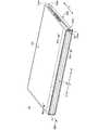
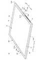
図1は、本発明の一実施形態に係る携帯用情報機器10を閉じて収納形態とした状態を示した斜視図である。図2は、図1に示す携帯用情報機器10を開いて使用形態とした状態を模式的に示した斜視図である。図3は、図2に示す携帯用情報機器10の内部構造を模式的に示した平面図である。
1. Description of Overall Configuration of Portable Information Device FIG. 1 is a perspective view showing a state in which theportable information device 10 according to an embodiment of the present invention is closed and stored. FIG. 2 is a perspective view schematically showing a state in which theportable information device 10 shown in FIG. 1 is opened for use. FIG. 3 is a plan view schematically showing the internal structure of theportable information device 10 shown in FIG.

図1及び図2に示すように、携帯用情報機器10は、第1筐体部材12A及び第2筐体部材12Bと、背表紙部材14と、ディスプレイ16とを備える。本実施形態では携帯用情報機器10として本のように二つ折りに折り畳み可能なタブレット型PCを例示する。携帯用情報機器10は携帯電話、スマートフォン又は電子手帳等であってもよい。  As shown in FIGS. 1 and 2, theportable information device 10 includes afirst housing member 12A and asecond housing member 12B, aspine member 14, and adisplay 16. In this embodiment, a tablet PC that can be folded in half like a book is illustrated as theportable information device 10. Theportable information device 10 may be a mobile phone, a smartphone, an electronic notebook, or the like.

各筐体部材12A,12Bは、それぞれ背表紙部材14に対応する辺以外の3辺に側壁を起立形成した矩形の板状部材である。各筐体部材12A,12Bは、例えばステンレスやマグネシウム、アルミニウム等の金属板や炭素繊維等の強化繊維を含む繊維強化樹脂板で構成される。筐体部材12A,12Bの内面側には、支持プレート18を介してディスプレイ16が固定される(図6Bも参照)。筐体部材12A,12B間は背表紙部材14の両端部に設けられた一対のヒンジ機構19,19を介して連結される。ヒンジ機構19は、筐体部材12A,12B間を図1に示す収納形態と図2に示す使用形態とに折り畳み可能に連結している。図3中に1点鎖線で示す線Cは、筐体部材12A,12Bの折り畳み動作の中心となる折曲中心Cを示している。  Each of thehousing members 12A and 12B is a rectangular plate-like member in which side walls are erected on three sides other than the side corresponding to thespine member 14. Each of thehousing members 12A and 12B is made of, for example, a fiber reinforced resin plate containing a metal plate of stainless steel, magnesium, aluminum or the like or a reinforcing fiber of carbon fiber or the like. Thedisplay 16 is fixed to the inner surface side of thehousing members 12A and 12B via the support plate 18 (see also FIG. 6B). Thehousing members 12A and 12B are connected to each other via a pair ofhinge mechanisms 19 and 19 provided at both ends of thespine member 14. Thehinge mechanism 19 foldably connects thehousing members 12A and 12B to the storage configuration shown in FIG. 1 and the usage configuration shown in FIG. A line C indicated by an alternate long and short dash line in FIG. 3 indicates a bending center C which is the center of the folding operation of thehousing members 12A and 12B.

各筐体部材12A,12Bは、背表紙部材14側の内端面12Aa,12Baがヒンジ側となり、背表紙部材14側とは反対側の外端面12Ab,12Bbが開放端部側となる。  In eachhousing member 12A, 12B, the inner end surface 12Aa, 12Ba on thespine member 14 side is on the hinge side, and the outer end surface 12Ab, 12Bb on the opposite side to thespine member 14 side is on the open end side.

図3に示すように、第1筐体部材12Aの内面には、メイン基板20、通信モジュール21及び冷却ファン22等が図示しないねじ等を用いて取付固定される。第2筐体部材12Bの内面には、サブ基板24、アンテナ25及びバッテリ装置26等が図示しないねじ等を用いて取付固定される。メイン基板20は、当該携帯用情報機器10の全体的な制御を行うための電子基板であり、図示しない中央演算装置(CPU)やメモリ等の各種電子部品が実装されている。通信モジュール21は、アンテナ25で送受信する無線LAN(Local Area Network)等の各種無線通信の情報処理を行うデバイスである。冷却ファン22は、メイン基板20に実装された中央演算装置等での発熱を冷却するためのファンである。サブ基板24は、ディスプレイ16の表示を制御するコントローラとして機能する電子基板である。バッテリ装置26は、当該携帯用情報機器10の電源であり、図示しない電源ケーブルを介して外部電源から充電可能である。  As shown in FIG. 3, themain substrate 20, thecommunication module 21, the coolingfan 22 and the like are attached and fixed to the inner surface of thefirst housing member 12A using screws and the like (not shown). Thesub substrate 24, theantenna 25, thebattery device 26 and the like are attached and fixed to the inner surface of thesecond housing member 12B using screws and the like (not shown). Themain substrate 20 is an electronic substrate for performing overall control of theportable information device 10, and various electronic components such as a central processing unit (CPU) and a memory (not shown) are mounted. Thecommunication module 21 is a device that performs information processing of various wireless communications such as a wireless LAN (Local Area Network) transmitted and received by theantenna 25. The coolingfan 22 is a fan for cooling heat generated by a central processing unit or the like mounted on themain substrate 20. Thesub substrate 24 is an electronic substrate that functions as a controller that controls the display of thedisplay 16. Thebattery device 26 is a power supply of theportable information device 10, and can be charged from an external power supply via a power supply cable (not shown).

ディスプレイ16は、例えばタッチパネル式の液晶ディスプレイである。ディスプレイ16は、筐体部材12A,12Bを折り畳んだ際に一緒に折り畳み可能な構造である。ディスプレイ16は、例えば柔軟性の高いペーパー構造を持った有機EL等のフレキシブルディスプレイであり、筐体部材12A,12Bの開閉動作に伴って開閉する。  Thedisplay 16 is, for example, a touch panel liquid crystal display. Thedisplay 16 is a structure that can be folded together when thehousing members 12A and 12B are folded. Thedisplay 16 is, for example, a flexible display such as an organic EL having a highly flexible paper structure, and is opened and closed in accordance with the opening and closing operation of thehousing members 12A and 12B.

ディスプレイ16は、支持プレート18を介して各筐体部材12A,12Bの内面側に図示しないねじを用いて取付固定される。ディスプレイ16は、その表示面(表面)の裏面が支持プレート18の表面に接着剤や両面テープ等を用いて貼着固定される。本実施形態の場合、支持プレート18は、各筐体部材12A,12Bの内面側にそれぞれ配置され、互いに折曲中心Cを中心として折曲可能に連結された一対のプレート部材18a,18aを有する(図6A及び図6B参照)。一対のプレート部材18a,18aは、その表面全域にシート状部材18bが固着され、これにより互いに折曲可能に連結されている。  Thedisplay 16 is attached and fixed to the inner surface side of each of thehousing members 12A and 12B via thesupport plate 18 using a screw (not shown). The back surface of the display surface (front surface) of thedisplay 16 is adhered and fixed to the front surface of thesupport plate 18 using an adhesive, double-sided tape or the like. In the case of the present embodiment, thesupport plate 18 includes a pair ofplate members 18a and 18a which are disposed on the inner surface side of therespective housing members 12A and 12B and are mutually foldably connected around the bending center C. (See FIGS. 6A and 6B). The sheet-like member 18b is fixed to the entire surface of the pair ofplate members 18a and 18a, and thereby, theplate members 18a and 18a are foldably connected to each other.

各プレート部材18aは、例えばステンレスやマグネシウム、アルミニウム等の金属板や炭素繊維等の強化繊維を熱硬化性樹脂や熱可塑性樹脂からなるマトリクス樹脂に含浸させた繊維強化樹脂板で構成される。本実施形態では、炭素繊維を強化樹脂とした炭素繊維強化樹脂板を用いている。シート状部材18bは、薄い樹脂膜や金属箔のような可撓性を持った材質で構成された薄膜である。シート状部材18bは、各プレート部材18a,18aの表面全域に亘って固着されている。本実施形態では、シート状部材18bとしてステンレス製の金属箔を用いている。ディスプレイ16は、シート状部材18bの表面に接着剤等を用いて接着される。シート状部材18bは、各プレート部材18aの隣接端部を覆う部分が支持プレート18の折曲部(フレキシブルヒンジ)として機能する。  Eachplate member 18a is formed of, for example, a fiber-reinforced resin plate obtained by impregnating a reinforcing plate such as a metal plate of stainless steel, magnesium, aluminum or the like or a carbon fiber with a thermosetting resin or a thermoplastic resin. In the present embodiment, a carbon fiber reinforced resin plate made of carbon fiber reinforced resin is used. The sheet-like member 18 b is a thin film made of a flexible material such as a thin resin film or metal foil. The sheet-like member 18b is fixed over the entire surface of eachplate member 18a, 18a. In the present embodiment, a metal foil made of stainless steel is used as the sheet-like member 18b. Thedisplay 16 is adhered to the surface of the sheet-like member 18b using an adhesive or the like. The sheet-like member 18 b functions as a bent portion (flexible hinge) of thesupport plate 18 in a portion covering the adjacent end of eachplate member 18 a.

支持プレート18は、筐体部材12A,12B間を平板状に開いた使用形態で、一対のプレート部材18a,18aの隣接する端面同士が当接する(図6B参照)。支持プレート18は、筐体部材12A,12B間を二つ折りに折り畳んだ収納形態では、一対のプレート部材18a,18aの隣接する端面同士が離間する(図6A参照)。  Thesupport plate 18 is used in a flat plate shape between thehousing members 12A and 12B, and adjacent end surfaces of the pair ofplate members 18a and 18a abut each other (see FIG. 6B). In the storage form in which thesupport plate 18 is folded in two between thehousing members 12A and 12B, the adjacent end surfaces of the pair ofplate members 18a and 18a are separated from each other (see FIG. 6A).

図2に示すように、ディスプレイ16は、筐体部材12A,12Bの内面側に取付固定された状態で、その表面の外周縁部にベゼル部材27が配設される(図8も参照)。ベゼル部材27は、ディスプレイ16の表面の表示領域(アクティブ領域)R1を除く外周縁部の非表示領域(非アクティブ領域)R2を覆うように設けられる。  As shown in FIG. 2, in a state where thedisplay 16 is attached and fixed to the inner surface side of thehousing members 12A and 12B, thebezel member 27 is disposed on the outer peripheral edge of the surface (see also FIG. 8). Thebezel member 27 is provided to cover the non-display area (inactive area) R2 of the outer peripheral edge excluding the display area (active area) R1 on the surface of thedisplay 16.

このように当該携帯用情報機器10は、一対の筐体部材12A,12Bを開閉することでその内側に設けたディスプレイ16を開閉し、図1に示す収納形態と図2に示す使用形態とに変形させることができる。  In this way, theportable information device 10 opens and closes thedisplay 16 provided inside by opening and closing the pair ofhousing members 12A and 12B, and the storage configuration shown in FIG. 1 and the usage configuration shown in FIG. It can be deformed.

以下、図1〜図3に示すように、携帯用情報機器10について、背表紙部材14から外端面12Ab,12Bbに向かう方向をX方向、背表紙部材14の長手方向に沿う方向をY方向と呼んで説明する。X方向については、背表紙部材14から一方の外端面12Abに向かう方向をX1方向、他方の外端面12Bbに向かう方向をX2方向と呼ぶこともある。同様にY方向については、背表紙部材14の長手方向で一方側(図3中で上側)に向かう方向をY1方向、他方側(図3中で下側)に向かう方向をY2方向と呼ぶこともある。  Hereinafter, as shown in FIGS. 1 to 3, in theportable information device 10, the direction from thespine member 14 toward the outer end face 12Ab, 12Bb is X direction, and the direction along the longitudinal direction of thespine member 14 is Y direction. Call and explain. Regarding the X direction, the direction from thespine member 14 toward the one outer end surface 12Ab may be referred to as the X1 direction, and the direction toward the other outer end surface 12Bb may be referred to as the X2 direction. Similarly, in the Y direction, the direction toward one side (upper side in FIG. 3) in the longitudinal direction of thespine member 14 is referred to as Y1 direction, and the direction toward the other side (lower side in FIG. 3) as the Y2 direction. There is also.

2.ヒンジ機構の説明
筐体部材12A,12B間を連結するヒンジ機構19の構成例を説明する。図4は、図1に示す携帯用情報機器10から背表紙部材14を省略した状態での要部拡大斜視図である。
2. Description of Hinge Mechanism A configuration example of thehinge mechanism 19 connecting thehousing members 12A and 12B will be described. FIG. 4 is an enlarged perspective view of an essential part of theportable information device 10 shown in FIG. 1 from which theback cover member 14 is omitted.

図3に示すように、ヒンジ機構19は、背表紙部材14の長手方向両端部に重なる位置にそれぞれ配設されている。各ヒンジ機構19は、ディスプレイ16の外形の外側となる位置に設けられ、互いに線対称構造である。ヒンジ機構19は、第1ヒンジ筐体28Aと、第2ヒンジ筐体28Bと、第1アーム30と、第2アーム31とを有する。  As shown in FIG. 3, thehinge mechanisms 19 are disposed at positions overlapping with both longitudinal end portions of thespine member 14. Thehinge mechanisms 19 are provided at positions outside the outline of thedisplay 16 and have a line symmetrical structure. Thehinge mechanism 19 includes afirst hinge housing 28A, asecond hinge housing 28B, afirst arm 30, and asecond arm 31.

第1ヒンジ筐体28Aは、樹脂や金属等で形成された薄型ブロック状の部品である。第1ヒンジ筐体28Aは、第1筐体部材12Aの内面上に固定ねじ32を用いて固定される。第2ヒンジ筐体28Bは、樹脂や金属等で形成された薄型ブロック状の部品である。第2ヒンジ筐体28Bは、第2筐体部材12Bの内面上に固定ねじ32を用いて固定される。  Thefirst hinge housing 28A is a thin block-shaped component formed of resin, metal or the like. Thefirst hinge housing 28A is fixed on the inner surface of thefirst housing member 12A using a fixingscrew 32. Thesecond hinge housing 28B is a thin block-shaped component formed of resin, metal or the like. Thesecond hinge housing 28B is fixed on the inner surface of thesecond housing member 12B using a fixingscrew 32.

第1ヒンジ筐体28Aは、第1筐体部材12Aの内面に着地する裏面側に凹状部34を有する。凹状部34は、第1ヒンジ筐体28Aの内側面(図3中の上側のヒンジ機構19ではY2側の側面)から折曲中心C側の側面(X2側の側面)までが開口した凹み形状である(図7A〜図8も参照)。第2ヒンジ筐体28Bは、第2筐体部材12Bの内面に着地する裏面側に凹状部35を有する。凹状部35は、第2ヒンジ筐体28Bの内側面(図3中の上側のヒンジ機構19ではY2側の側面)から折曲中心C側の側面(X1側の側面)までが開口した凹み形状である(図7A〜図8も参照)。各凹状部34,35は、折曲中心Cを挟んで互いに連通している(図3及び図7B参照)。  Thefirst hinge housing 28A has aconcave portion 34 on the back surface side that contacts the inner surface of thefirst housing member 12A. Theconcave portion 34 has a concave shape in which the inner side surface (the side surface on the Y2 side in theupper hinge mechanism 19 in FIG. 3) of thefirst hinge housing 28A opens to the side surface (the side surface on the X2 side) on the bending center C side. (See also FIGS. 7A-8). The second hinge housing 28 </ b> B has aconcave portion 35 on the back surface side of the inner surface of the second housing member 12 </ b> B. Theconcave portion 35 has a concave shape in which the inner side surface (the side surface on the Y2 side in theupper hinge mechanism 19 in FIG. 3) of thesecond hinge housing 28B is opened to the side surface (the side surface on the X1 side) on the bending center C side. (See also FIGS. 7A-8). The respectiveconcave portions 34, 35 communicate with each other across the bending center C (see FIGS. 3 and 7B).

第1アーム30は、一端部が第1ヒンジ筐体28Aに対して第1ヒンジ軸36aを介して回動可能に連結される一方、他端部が第2ヒンジ筐体28Bに対して第2ヒンジ軸36bを介して回動可能に連結される(図7A及び図7Bも参照)。第2アーム31は、一端部が第2ヒンジ筐体28Bに対して第3ヒンジ軸36cを介して回動可能に連結される一方、他端部が第1ヒンジ筐体28Aに対して第4ヒンジ軸36dを介して回動可能に連結される(図7A及び図7Bも参照)。  One end of thefirst arm 30 is pivotably connected to thefirst hinge housing 28A via thefirst hinge shaft 36a, while the other end is second to thesecond hinge housing 28B. It is rotatably connected via ahinge shaft 36b (see also FIGS. 7A and 7B). Thesecond arm 31 has one end rotatably coupled to thesecond hinge housing 28B via thethird hinge shaft 36c, and the other end fourth to thefirst hinge housing 28A. It is rotatably connected via ahinge shaft 36d (see also FIGS. 7A and 7B).

第1アーム30と第2アーム31は、Y方向に並列されている。第1アーム30の第2ヒンジ軸36bは、第2アーム31の第3ヒンジ軸36cと第4ヒンジ軸36dの間に挟まれた位置にある。第2アーム31の第3ヒンジ軸36cは、第1アーム30の第1ヒンジ軸36aと第2ヒンジ軸36bの間に挟まれた位置にある。これにより、第1アーム30と第2アーム31は、X方向及びY方向に位置ずれして互い違いに並んでいる。  Thefirst arm 30 and thesecond arm 31 are arranged in parallel in the Y direction. Thesecond hinge shaft 36 b of thefirst arm 30 is located between thethird hinge shaft 36 c and thefourth hinge shaft 36 d of thesecond arm 31. Thethird hinge shaft 36 c of thesecond arm 31 is located between thefirst hinge shaft 36 a and thesecond hinge shaft 36 b of thefirst arm 30. As a result, thefirst arm 30 and thesecond arm 31 are staggered in the X and Y directions.

各ヒンジ機構19は、筐体部材12A,12B間が折曲中心Cを中心に折り畳まれると、各ヒンジ軸36a〜36dを介して各アーム30,31が回動する(図4参照)。これにより、ヒンジ機構19は、筐体部材12A,12B間を二つ折りに折り畳んだ状態から平板状に開いた状態まで回動可能に連結している。  In eachhinge mechanism 19, when the space between thehousing members 12A and 12B is folded around the bending center C, thearms 30 and 31 rotate via thehinge shafts 36a to 36d (see FIG. 4). Thus, thehinge mechanism 19 is rotatably connected from the state in which thehousing members 12A and 12B are folded in two to the state in which thehousing members 12A and 12B are opened in a flat plate shape.

3.背表紙部材の説明
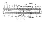
背表紙部材14について説明する。図1に示す収納形態では、筐体部材12A,12B間の内端面12Aa,12Ba間が大きく離間して隙間を生じる(図4も参照)。そこで、当該携帯用情報機器10では、この隙間を覆うことで内部のディスプレイ16やメイン基板20、バッテリ装置26等の各要素が露呈することを防止するために背表紙部材14を設けている。図5は、背表紙部材14の分解斜視図である。図6Aは、図1中のVIA−VIA線に沿う断面構造を模式的に示した断面図である。図6Bは、図3中のVIB−VIB線に沿う断面構造を模式的に示した断面図である。
3. Description of Back Cover Member Theback cover member 14 will be described. In the storage mode shown in FIG. 1, the inner end surfaces 12Aa and 12Ba between thehousing members 12A and 12B are largely separated to form a gap (see also FIG. 4). Therefore, in theportable information device 10, theback cover member 14 is provided in order to prevent the elements such as theinternal display 16, themain substrate 20, and thebattery device 26 from being exposed by covering the gap. FIG. 5 is an exploded perspective view of thespine member 14. 6A is a cross-sectional view schematically showing a cross-sectional structure taken along line VIA-VIA in FIG. FIG. 6B is a cross-sectional view schematically showing a cross-sectional structure along a VIB-VIB line in FIG. 3.

背表紙部材14は、携帯用情報機器10を折り畳んだ際の背表紙となる部材であり、可撓性を持った薄い板状部材である。背表紙部材14は内端面12Aa,12Ba間を跨ぎながら内側から覆うように筐体部材12A,12B間に亘って設けられている(図3、図6A及び図6B参照)。  Theback cover member 14 is a member to be a back cover when theportable information device 10 is folded, and is a flexible thin plate member. Theback cover member 14 is provided across thehousing members 12A and 12B so as to cover from the inside while straddling the inner end surfaces 12Aa and 12Ba (see FIGS. 3, 6A and 6B).

図5に示すように、背表紙部材14は、シート状部材(可撓性シート状部材)40と、第1支持部材42と、第2支持部材43と、複数枚の補強部材44a,44b,44c,44dとを有する。  As shown in FIG. 5, thespine member 14 includes a sheet-like member (flexible sheet-like member) 40, afirst support member 42, asecond support member 43, and a plurality of reinforcingmembers 44 a and 44 b, 44c and 44d.

第1支持部材42及び第2支持部材43は、背表紙部材14の長手方向(Y方向)に延在する薄い板状部材である。補強部材44a〜44dは、背表紙部材14の長手方向に延在する薄い板状部材であり、支持部材42,43よりもX方向に幅狭である。補強部材44a〜44dは、それぞれ支持部材42,43間で第1筐体部材12Aから第2筐体部材12Bに向かうX2方向に並んでいる。第1支持部材42、第2支持部材43及び補強部材44a〜44dは、樹脂や金属等で形成された薄いプレート部材である。  Thefirst support member 42 and thesecond support member 43 are thin plate members extending in the longitudinal direction (Y direction) of thespine member 14. The reinforcingmembers 44 a to 44 d are thin plate members extending in the longitudinal direction of thespine member 14, and are narrower in the X direction than thesupport members 42 and 43. The reinforcingmembers 44a to 44d are arranged between thesupport members 42 and 43 in the X2 direction from thefirst housing member 12A to thesecond housing member 12B. Thefirst support member 42, thesecond support member 43, and the reinforcingmembers 44a to 44d are thin plate members made of resin, metal or the like.

シート状部材40は、炭素繊維等の強化繊維にエポキシ樹脂等の熱硬化性樹脂を含浸させた繊維強化樹脂板である。シート状部材40は、例えば0.3mm以下の薄いシート状部材であり、可撓性を有すると共に高強度である。強化繊維としては、ステンレス繊維等の金属繊維やガラス繊維等の無機繊維等、各種材料を用いてもよい。シート状部材40は、樹脂膜や金属箔等で形成されてもよい。  The sheet-like member 40 is a fiber-reinforced resin plate in which reinforcing fibers such as carbon fibers are impregnated with a thermosetting resin such as an epoxy resin. The sheet-like member 40 is a thin sheet-like member of 0.3 mm or less, for example, and has flexibility and high strength. As the reinforcing fibers, various materials such as metal fibers such as stainless steel fibers and inorganic fibers such as glass fibers may be used. The sheet-like member 40 may be formed of a resin film, a metal foil or the like.

各支持部材42,43及び各補強部材44a〜44dは、接着剤や両面テープ等を用いてシート状部材40の表面に固着される。これにより、背表紙部材14は、筐体部材12A,12Bの折り畳み動作に伴って折り曲げ可能である。シート状部材40は、筐体部材12A,12Bの内端面12Aa,12Ba間を覆う部分が折曲部40aとなる(図6A及び図6B参照)。シート状部材40は、第2支持部材43側の縁部にY方向に並んで複数の切欠部40bを有する。  Thesupport members 42 and 43 and the reinforcingmembers 44 a to 44 d are fixed to the surface of the sheet-like member 40 using an adhesive, a double-sided tape, or the like. Thereby, thespine member 14 can be folded along with the folding operation of thehousing members 12A and 12B. In the sheet-like member 40, a portion covering between the inner end faces 12Aa and 12Ba of thehousing members 12A and 12B is abent portion 40a (see FIGS. 6A and 6B). The sheet-like member 40 has a plurality ofnotches 40 b aligned in the Y direction at the edge on thesecond support member 43 side.

第1支持部材42は、第1筐体部材12Aの内面側で該内面に沿って筐体部材12A,12B間に亘るX方向にスライド可能に設けられる。第1支持部材42は、その長手方向で両端部の表面にそれぞれ押さえ面42aを有する。押さえ面42aは、第1支持部材42の他の表面よりも一段低い面である。第1支持部材42は、長手方向で一対の押さえ面42a,42a間となる部分の表面にX方向の溝部42bを複数有する。第1支持部材42の補強部材44aに対向するX2側の側面42cは、裏面側(シート状部材40側)から表面側に向かう方向で補強部材44a側からX1方向に後退する傾斜面となっている(図6A及び図6B参照)。  Thefirst support member 42 is provided slidably along the inner surface on the inner surface side of thefirst housing member 12A in the X direction extending between thehousing members 12A and 12B. Thefirst support member 42 haspressing surfaces 42a on the surfaces of both ends in the longitudinal direction. Thepressing surface 42 a is a surface one step lower than the other surface of thefirst support member 42. Thefirst support member 42 has a plurality ofgroove portions 42b in the X direction on the surface of the portion which is to be between the pair ofpressing surfaces 42a and 42a in the longitudinal direction. Theside surface 42c on the X2 side facing the reinforcingmember 44a of thefirst support member 42 is an inclined surface that retracts in the X1 direction from the reinforcingmember 44a side in the direction from the back surface side (sheet member 40 side) to the front surface side. (See FIGS. 6A and 6B).

第1支持部材42は、X方向に沿って引張ばね(弾性部材)45による付勢力を受けている(図3及び図6A参照)。引張ばね45は、第2筐体部材12Bから第1筐体部材12Aに向かうX1方向に沿って背表紙部材14を常時付勢している。  Thefirst support member 42 receives a biasing force from a tension spring (elastic member) 45 along the X direction (see FIGS. 3 and 6A). Thetension spring 45 always biases thespine member 14 along the X1 direction from thesecond housing member 12B toward thefirst housing member 12A.

第2支持部材43は、第2筐体部材12Bの内面側で該内面に対して固定ねじ46を用いてスライド不能に取付固定される(図6A及び図6B参照)。第2支持部材43は、その長手方向で両端部の表面にそれぞれ押さえ面43aを有する。押さえ面43aは、第2支持部材43の他の表面よりも一段低い面である。第2支持部材43は、一対の押さえ面43a,43a間となる部分の表面にX方向の溝部43bを複数有する。第2支持部材43の長手方向適宜位置には、固定ねじ46のねじ部を挿通するための貫通孔47が設けられている。固定ねじ46は、シート状部材40の切欠部40bを通して第2筐体部材12Bに締結固定される。第2支持部材43の補強部材44dに対向するX1側の側面43cは、裏面側(シート状部材40側)から表面側に向かう方向で補強部材44d側からX2方向に後退する傾斜面となっている(図6A及び図6B参照)。  Thesecond support member 43 is non-slidably attached and fixed to the inner surface of thesecond housing member 12B using the fixing screw 46 (see FIGS. 6A and 6B). Thesecond support member 43 haspressing surfaces 43a on the surfaces of both ends in the longitudinal direction. Thepressing surface 43 a is a surface one step lower than the other surface of thesecond support member 43. Thesecond support member 43 has a plurality ofgroove portions 43b in the X direction on the surface of the portion that is between the pair ofpressing surfaces 43a and 43a. Throughholes 47 for inserting the screw portion of the fixingscrew 46 are provided at appropriate positions in the longitudinal direction of thesecond support member 43. The fixingscrew 46 is fastened and fixed to thesecond housing member 12B through thenotch 40b of the sheet-like member 40. Theside surface 43c on the X1 side facing the reinforcingmember 44d of thesecond support member 43 is an inclined surface that retracts in the X2 direction from the reinforcingmember 44d side in the direction from the back surface side (sheet member 40 side) to the front surface side. (See FIGS. 6A and 6B).

各補強部材44a〜44dは、上底及び下底が多少湾曲した台形状の断面形状を有する。各補強部材44a〜44dの長手方向両端部の表面には、他の表面よりも一段低い面である押さえ面44eがそれぞれ設けられている(図5参照)。各押さえ面44eは、各支持部材42,43の押さえ面42a,43aと略同程度の高さ位置に形成されている(図7B参照)。補強部材44a〜44dの設置本数は適宜変更可能である。  Each reinforcingmember 44a to 44d has a trapezoidal cross-sectional shape in which the upper and lower bases are somewhat curved. Pressingsurfaces 44e, which are surfaces one step lower than the other surfaces, are respectively provided on the surfaces of both longitudinal direction end portions of the reinforcingmembers 44a to 44d (see FIG. 5). Eachpressing surface 44e is formed at a height position substantially equal to that of thepressing surfaces 42a and 43a of thesupport members 42 and 43 (see FIG. 7B). The number of reinforcingmembers 44a to 44d can be changed as appropriate.

各補強部材44a〜44dは、第1支持部材42側(X1側)の側面48aと、第2支持部材43側(X2側)の側面48bとを有する(図6A及び図6B参照)。第1支持部材42側に近い2つの補強部材44a,44bと、第2支持部材43側に近い2つの補強部材44c,44dとは、中央の補強部材44b,44c間の境界線を基準として互いに略線対称形状である。補強部材44aの側面48aは、裏面側(シート状部材40側)から表面側に向かう方向で第1支持部材42側からX2方向に後退する傾斜面となっている。補強部材44dの側面48bは、裏面側(シート状部材40側)から表面側に向かう方向で第2支持部材43側からX1方向に後退する傾斜面となっている。その他の側面48a,48bは、それぞれ対向する側面48b,48aと略平行に対面し、或いは互いに多少離間する方向の傾斜面となっている。  Eachreinforcement member 44a to 44d has aside surface 48a on thefirst support member 42 side (X1 side) and aside surface 48b on thesecond support member 43 side (X2 side) (see FIGS. 6A and 6B). The two reinforcingmembers 44a and 44b close to thefirst support member 42 and the tworeinforcement members 44c and 44d close to thesecond support member 43 mutually refer to the boundary between thecentral reinforcement members 44b and 44c. It has a substantially line symmetrical shape. Theside surface 48a of the reinforcingmember 44a is an inclined surface which recedes in the X2 direction from thefirst support member 42 in the direction from the back surface side (sheet-like member 40 side) to the front surface side. Theside surface 48b of the reinforcingmember 44d is an inclined surface which recedes in the X1 direction from thesecond support member 43 in the direction from the back surface side (sheet-like member 40 side) to the front surface side. Theother side surfaces 48a and 48b are inclined surfaces facing in a direction substantially parallel to the opposing side surfaces 48b and 48a, or in a direction slightly away from each other.

図6Aに示す収納形態では、各補強部材44a〜44dは二つ折りに折り曲げられたシート状部材40の折曲部40aの内面側で互いの側面48a,48b同士が当接し、複数の歯が隙間なく並んだようなアーチ形状(円弧形状)を形成する。この際、両端の補強部材44a,44dの外側の側面48a,48bは、それぞれ各支持部材42,43の側面42c,43cに当接する。このアーチ形状により各補強部材44a〜44dは、内端面12Aa,12Ba間が離間して剛性が低下した収納形態の筐体部材12A,12B間を強固に支持する支柱として機能する。すなわち、筐体部材12A,12B間の背表紙部材14付近は、収納形態でY方向両端部にはヒンジ機構19が設けられるものの、両端部以外の部分は何ら剛性のない部分がY方向に延在する。そこで、当該携帯用情報機器10では、支持部材42,43及び補強部材44a〜44bがY方向に延在するアーチ形状の支柱を形成し、収納形態での厚み方向の剛性を担保している。  In the storage form shown in FIG. 6A, the respective reinforcingmembers 44a to 44d are in contact with the side surfaces 48a and 48b on the inner surface side of thebent portion 40a of the sheet-like member 40 folded in two, and a plurality of teeth are clearances It forms an arch shape (arc shape) that seems to be side by side. At this time, theouter side surfaces 48a and 48b of the reinforcingmembers 44a and 44d at both ends abut on the side surfaces 42c and 43c of thesupport members 42 and 43, respectively. Due to this arch shape, each of the reinforcingmembers 44a to 44d functions as a support for firmly supporting between thehousing members 12A and 12B of the storage form in which the rigidity is lowered by separating the inner end surfaces 12Aa and 12Ba. That is, although thehinge mechanism 19 is provided at both ends in the Y direction in the storage configuration in the vicinity of theback cover member 14 between thehousing members 12A and 12B, parts having no rigidity extend in the Y direction except for both ends. Exist. Therefore, in theportable information device 10, the supportingmembers 42 and 43 and the reinforcingmembers 44a to 44b form arch-shaped columns extending in the Y direction, and secure the rigidity in the thickness direction in the storage configuration.

このような収納形態では、筐体部材12A,12Bの内端面12Aa,12Ba間が最も離間した位置に配置される。このため背表紙部材14は、スライド側である第1支持部材42側が第1筐体部材12Aの内面上で最も内端面12Aa側(X2方向)に引寄せられた後退位置となる。その際、第1支持部材42は引張ばね45の付勢力に抗して内端面12Aa側にスライドする。  In such a storage mode, the inner end surfaces 12Aa and 12Ba of thehousing members 12A and 12B are disposed at the most distant position. Therefore, theback cover member 14 is at the retracted position where thefirst support member 42 side which is the slide side is drawn closest to the inner end surface 12Aa side (X2 direction) on the inner surface of thefirst housing member 12A. At that time, thefirst support member 42 slides against the biasing force of thetension spring 45 toward the inner end surface 12Aa.

一方、筐体部材12A,12B間が平板状に開かれた使用形態では、各補強部材44a〜44dは筐体部材12A,12Bの内面上に各支持部材42,43と共に一列に並んで配置される。このため、背表紙部材14は最小限の厚みを持った平板状の形態となる。この使用形態では、筐体部材12A,12Bの内端面12Aa,12Ba間が最も近接又は当接した位置に配置される。このため背表紙部材14は、スライド側である第1支持部材42側が第1筐体部材12Aの内面上で最も内端面12Aa側とは反対の外端面12Ab側(X1方向)に進んだ前進位置となる。その際、第1支持部材42は引張ばね45の付勢力によって円滑に外端面12Ab側にスライドするため、背表紙部材14がスライド時に浮き上がりや引っ掛かりを生じることがない。  On the other hand, in the usage form in which the space between thehousing members 12A and 12B is opened like a flat plate, the reinforcingmembers 44a to 44d are arranged in a row along with thesupport members 42 and 43 on the inner surface of thehousing members 12A and 12B. Ru. For this reason, thespine member 14 is in the form of a flat plate having a minimum thickness. In this mode of use, the inner end surfaces 12Aa and 12Ba of thehousing members 12A and 12B are disposed at the closest position or in the contact position. For this reason, theback cover member 14 is at an advanced position where thefirst support member 42 side on the slide side has advanced to the outer end surface 12Ab side (X1 direction) opposite to the inner end surface 12Aa side on the inner surface of thefirst housing member 12A. It becomes. At this time, since thefirst support member 42 slides smoothly to the outer end face 12Ab by the biasing force of thetension spring 45, thespine member 14 does not lift up or get caught when sliding.

なお、溝部42b,43bには、左右の筐体部材12A,12B間に亘り、例えばメイン基板20とサブ基板24との間を接続する配線49が通される。溝部42b,43bの上部開口は、蓋部材51(図6A参照)によって蓋される。蓋部材51は、薄い樹脂膜や金属箔のような可撓性を持った材質で構成された薄膜である。蓋部材51は、背表紙部材14のY方向両端部を除く略全長に亘って、且つX方向全幅に亘って設けられ、背表紙部材14の表面に貼着されている。本実施形態の場合、蓋部材51には、ステンレス製のシート状部材(ステンレスシート)を用いている。蓋部材51は、例えばX2側の端部が第2支持部材43の表面に固着され、X1側の端部が第1支持部材42の表面に移動可能に載置されている(図6A及び図6B参照)。このため、蓋部材51は、背表紙部材14のスライドに追従して背表紙部材14上をスライドしつつ、配線49の溝部42b,43bからの脱落を防止する。このため、配線49が溝部42b,43bの上部開口から浮き上がり、溝部42b,43bの外部に脱落することを防止できる。このように、携帯用情報機器10では、金属箔からなる蓋部材51によって溝部42b,43bを塞ぎ、配線49の脱落を防止している。このため、例えば図6Aに示す収納形態から図6Bに示す使用形態に変化させる際、支持プレート18の一対のプレート部材18a,18aの折曲動作に追従するように蓋部材51も背表紙部材14と共に折り曲げられる。その結果、各プレート部材18a,18a間の隣接端部(エッジ)等に配線49が接触することを確実に防止でき、当該携帯用情報機器10の耐久性、信頼性が向上する。なお、蓋部材51のスライド側の端部であるX1側の端部を、第1支持部材42のX1側端部を越えて延在させるように構成してもよい。これにより、配線49が背表紙部材14と重なる領域よりもより広範囲に配線49を保護することができる。  For example, awire 49 connecting between themain substrate 20 and thesub substrate 24 is passed through thegroove portions 42b and 43b across the left andright housing members 12A and 12B. The upper openings of thegrooves 42b and 43b are covered by a cover member 51 (see FIG. 6A). Thelid member 51 is a thin film made of a flexible material such as a thin resin film or metal foil. Thelid member 51 is provided over substantially the entire length of thespine member 14 except for both end portions in the Y direction and across the entire width in the X direction, and is adhered to the surface of thespine member 14. In the case of the present embodiment, a sheet-like member (stainless steel sheet) made of stainless steel is used for thelid member 51. For example, the end on the X2 side of thelid member 51 is fixed to the surface of thesecond support member 43, and the end on the X1 side is movably mounted on the surface of the first support member 42 (FIG. 6A and FIG. 6B). Therefore, thelid member 51 slides on thespine member 14 following the slide of thespine member 14 and prevents thewire 49 from coming off thegrooves 42 b and 43 b. Therefore, thewiring 49 can be prevented from rising from the upper openings of thegroove portions 42 b and 43 b and falling off thegroove portions 42 b and 43 b. As described above, in theportable information device 10, thegrooves 42b and 43b are closed by thelid member 51 made of metal foil to prevent thewire 49 from falling off. For this reason, for example, when changing from the storage form shown in FIG. 6A to the use form shown in FIG. Along with As a result, thewiring 49 can be reliably prevented from contacting the adjacent end portion (edge) or the like between theplate members 18a and 18a, and the durability and the reliability of theportable information device 10 are improved. The end on the X1 side that is the end on the slide side of thelid member 51 may be configured to extend beyond the X1 side end of thefirst support member 42. Thereby, thewire 49 can be protected in a wider range than the region where thewire 49 overlaps with thespine member 14.

4.背表紙部材とヒンジ機構の関係の説明
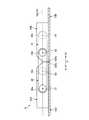
背表紙部材14とヒンジ機構19の関係を説明する。図7Aは、図1中のVIIA−VIIA線に沿う断面構造を模式的に示した断面図である。図7Bは、図3中のVIIB−VIIB線に沿う断面構造を模式的に示した断面図である。図8は、図2中のVIII−VIII線に沿う断面構造を模式的に示した断面図である。
4. Description of Relationship Between Back Cover Member and Hinge Mechanism The relationship between theback cover member 14 and thehinge mechanism 19 will be described. 7A is a cross-sectional view schematically showing a cross-sectional structure taken along the line VIIA-VIIA in FIG. FIG. 7B is a cross-sectional view schematically showing a cross-sectional structure along the line VIIB-VIIB in FIG. 3. FIG. 8 is a cross-sectional view schematically showing a cross-sectional structure taken along line VIII-VIII in FIG.

図1及び図4に示すように、背表紙部材14は各ヒンジ機構19の裏面側を覆う位置まで延在し、ヒンジ機構19が筐体部材12A,12Bの内端面12Aa,12Ba間から露呈することを防止している。  As shown in FIGS. 1 and 4, thespine member 14 extends to a position covering the back side of eachhinge mechanism 19, and thehinge mechanism 19 is exposed from between the inner end faces 12Aa and 12Ba of thehousing members 12A and 12B. To prevent that.

図3、図7A、図7B及び図8に示すように、背表紙部材14は、その長手方向両端部の押さえ面42a,43a,44eが各ヒンジ筐体28A,28Bの裏面と筐体部材12A,12Bの内面との間に保持される。具体的には、背表紙部材14の各押さえ面42a,43a,44eは、ヒンジ筐体28A,28Bの凹状部34,35に挿入配置される。この際、少なくとも第1支持部材42及び各補強部材44a〜44dの押さえ面42a,44eは、第1支持部材42の凹状部34内でスライド可能に保持され、第1筐体12Aの内面と凹状部34の天面との間でガイドされる。つまり、第1ヒンジ筐体28A側の凹状部34は、背表紙部材14をX方向にスライド可能にガイドし、スライド時の浮き上がり等を防止する。この凹状部34は背表紙部材14のスライド距離(スライド範囲)L(図7A参照)に対応可能な長さ寸法を有する。このため、凹状部34は第2ヒンジ筐体28B側の凹状部35よりもX方向に長尺である。  As shown in FIG. 3, FIG. 7A, FIG. 7B and FIG. 8, theback cover member 14 has thepressing surfaces 42a, 43a, 44e at both ends in the longitudinal direction on the back surface of eachhinge case 28A, 28B and thecase member 12A. , 12B, and held between them. Specifically, thepressing surfaces 42a, 43a, 44e of thespine member 14 are inserted into theconcave portions 34, 35 of thehinge housings 28A, 28B. At this time, at least thepressing surfaces 42a and 44e of thefirst support member 42 and the reinforcingmembers 44a to 44d are slidably held in theconcave portion 34 of thefirst support member 42, and the inner surface of thefirst housing 12A and the concave It is guided between the top surface of thepart 34. That is, theconcave portion 34 on the side of thefirst hinge housing 28A slidably guides thespine member 14 in the X direction to prevent floating or the like at the time of sliding. Theconcave portion 34 has a length that can correspond to the sliding distance (sliding range) L (see FIG. 7A) of thespine member 14. Therefore, theconcave portion 34 is longer in the X direction than theconcave portion 35 on thesecond hinge housing 28B side.

図8に示すように、ヒンジ機構19は、各ヒンジ筐体28A,28Bの外側面にそれぞれ嵌合凸部50を有する。一方、この嵌合凸部50と対向する各筐体部材12A,12Bの内面から起立したX方向に沿う側壁である壁部52の内側面には嵌合凹部52aが形成されている。嵌合凹部52aは嵌合凸部50が嵌合可能であり、少なくとも嵌合凸部50が筐体部材12A,12Bの内面から上昇する方向の移動を規制するものである。  As shown in FIG. 8, thehinge mechanism 19 hasfitting projections 50 on the outer side surfaces of the hinge housings 28 </ b> A and 28 </ b> B. On the other hand, afitting recess 52a is formed on the inner side surface of thewall 52 which is a side wall along the X direction which stands up from the inner surface of eachcase member 12A, 12B facing thefitting protrusion 50. The fittingconvex portion 50 can be fitted in the fittingconcave portion 52a, and at least the movement of the fittingconvex portion 50 in the direction of rising from the inner surface of thehousing members 12A and 12B is restricted.

従って、第1ヒンジ筐体28Aは、第1筐体部材12Aの内面と壁部52の嵌合凹部52aの天面との間に挟持され、その浮き上がりが防止される。第2ヒンジ筐体28Bは、第2筐体部材12Bの内面と壁部52の嵌合凹部52aの天面との間に挟持され、その浮き上がりが防止される。すなわち、ヒンジ筐体28A,28Bは、その裏面側に背表紙部材14を挿入する凹状部34,35を設けているため、固定ねじ32はこの凹状部34,35の周囲にしか締結できない。このため、ヒンジ機構19の可動時にヒンジ筐体28A,28Bが浮き上がりを生じる懸念もある。そこで、当該携帯用情報機器10ではヒンジ筐体28A,28Bを筐体部材12A,12Bの壁部52に嵌合させて押さえ付け、その浮き上がりを防止している。なお、各ヒンジ筐体28A,28Bは、嵌合凸部50を設けずに嵌合凹部52aに嵌合させてもよい。  Therefore, thefirst hinge housing 28A is sandwiched between the inner surface of thefirst housing member 12A and the top surface of thefitting recess 52a of thewall 52, and the floating thereof is prevented. Thesecond hinge housing 28B is sandwiched between the inner surface of thesecond housing member 12B and the top surface of thefitting recess 52a of thewall 52, and the floating thereof is prevented. That is, since thehinge casings 28A and 28B have theconcave portions 34 and 35 for inserting theback cover member 14 on the back side, the fixingscrew 32 can be fastened only around theconcave portions 34 and 35. Therefore, there is a concern that thehinge housings 28A and 28B may be lifted when thehinge mechanism 19 is moved. Therefore, in theportable information device 10, thehinge cases 28A and 28B are fitted to thewall 52 of thecase members 12A and 12B and pressed down to prevent the floating thereof. Each of thehinge casings 28A and 28B may be fitted in thefitting recess 52a without providing thefitting protrusion 50.

5.ディスプレイとヒンジ機構の位置関係の説明
ディスプレイ16とヒンジ機構19の位置関係を説明する。図9は、ディスプレイ16とヒンジ機構19の位置関係を示す要部拡大斜視図である。図10A〜図10Dは、一対の筐体部材12A,12B間を開いた状態から閉じた状態まで回動させた場合のディスプレイ16とヒンジ機構19の位置関係を模式的に示した側面動作図である。図10A〜図10Dは図面の見易さを考慮して背表紙部材14等の要素の図示を省略すると共に、第2アーム31及びヒンジ軸36c,36dを破線で図示している。
5. Description of positional relationship between display and hinge mechanism The positional relationship between thedisplay 16 and thehinge mechanism 19 will be described. FIG. 9 is an enlarged perspective view of an essential part showing the positional relationship between thedisplay 16 and thehinge mechanism 19. 10A to 10D are side operation diagrams schematically showing the positional relationship between thedisplay 16 and thehinge mechanism 19 when the pair ofhousing members 12A and 12B is rotated from the open state to the closed state. is there. 10A to 10D omit illustration of elements such as thespine member 14 etc. in consideration of the legibility of the drawings, and also show thesecond arm 31 and thehinge shafts 36c and 36d by broken lines.

先ず上記した通り、ディスプレイ16は支持プレート18を介して各筐体部材12A,12Bに取付固定されている。また、各ヒンジ機構19は各筐体部材12A,12Bの一縁部(内端面12Aa,12Ba)の長手方向(Y方向)両端部のそれぞれに配置されると共に、ディスプレイ16の外形の外側となる位置に設けられている。  First, as described above, thedisplay 16 is attached and fixed to each of thehousing members 12A and 12B via thesupport plate 18. Further, eachhinge mechanism 19 is disposed at each end of one edge (inner end face 12Aa, 12Ba) of eachhousing member 12A, 12B in the longitudinal direction (Y direction) and is outside the outer shape of thedisplay 16 It is provided in the position.

ディスプレイ16の取付構造は限定されないが、例えば図3に示すように支持プレート18の取付片18cを介して筐体部材12A,12Bが位置決め固定される。取付片18cは、支持プレート18の外周縁部の適宜位置に設けられ、プレート部材18aの外周縁部から外方に突出した突出片である。取付片18cは、中央にねじ止め用の貫通孔が形成されている。この貫通孔を介して固定ねじ54を各筐体部材12A,12Bに締結することで、支持プレート18(ディスプレイ16)が筐体部材12A,12Bに締結固定される。  Although the attachment structure of thedisplay 16 is not limited, for example, as shown in FIG. 3, thehousing members 12A and 12B are positioned and fixed via theattachment piece 18c of thesupport plate 18. The mountingpieces 18c are provided at appropriate positions on the outer peripheral edge of thesupport plate 18, and are projecting pieces that protrude outward from the outer peripheral edge of theplate member 18a. The mountingpiece 18c is formed with a through hole for screwing at the center. The support plate 18 (display 16) is fastened and fixed to thehousing members 12A and 12B by fastening the fixing screws 54 to thehousing members 12A and 12B through the through holes.

なお、ディスプレイ16は二つ折りに折り畳まれる。このため、支持プレート18(ディスプレイ16)は背表紙部材14の折曲部40aに対応する位置には取付片18cを設けていない。つまり、ディスプレイ16は、背表紙部材14に対応する部分である折曲領域R3(図3及び図6A参照)は筐体部材12A,12Bに固定されず、これ以外の部分で位置決め固定されている。取付片18cに代えて、例えばプレート部材18aの下面にボス状の雌ねじ部等を設けてもよい。  Thedisplay 16 is folded in half. For this reason, the support plate 18 (display 16) is not provided with theattachment piece 18c at a position corresponding to the bendingportion 40a of thespine member 14. That is, in thedisplay 16, the bending region R3 (see FIGS. 3 and 6A) corresponding to thespine member 14 is not fixed to thehousing members 12A and 12B, but is positioned and fixed at other parts. . For example, a boss-shaped female screw or the like may be provided on the lower surface of theplate member 18a instead of theattachment piece 18c.

このように当該携帯用情報機器10では、ディスプレイ16が筐体部材12A,12Bに位置決め固定された状態で二つ折りに折り畳まれる。このため、ディスプレイ16とヒンジ機構19の各ヒンジ軸36a〜36dとの位置関係によっては、開閉動作時にディスプレイ16の折曲領域R3の負荷が増大し、ディスプレイ16の円滑な折り曲げができなくなる可能性がある。  As described above, in theportable information device 10, thedisplay 16 is folded in half in a state where thedisplay 16 is positioned and fixed to thehousing members 12A and 12B. Therefore, depending on the positional relationship between thedisplay 16 and thehinge shafts 36a to 36d of thehinge mechanism 19, the load on the bending region R3 of thedisplay 16 may increase during the opening and closing operation, and thedisplay 16 may not be smoothly bent. There is.

そこで当該携帯用情報機器10では、図10Aに示すように第1筐体部材12Aと第2筐体部材12Bとを平板状に開いた状態(使用形態)で、ディスプレイ16の表面16aとヒンジ軸36a〜36dの軸中心A1〜A4とが同一平面上に配置される構成としている。換言すれば、平板状に開いた状態のディスプレイ16の表面16aと一致する仮想平面上に軸中心A1〜A4が配置される。これにより、図10Aに示す使用形態から筐体部材12A,12B間を折り畳み動作させると、図10B及び図10Cに示すように各アーム30,31が各ヒンジ軸36a〜36dで回動して筐体部材12A,12B間が次第に折り畳まれ、ディスプレイ16も折り曲げされる。最終的には、図10Dに示すように各筐体部材12A,12B間が二つ折りに折り畳まれ、ディスプレイ16も設計上の所定曲率の円弧を描いた二つ折りに折り畳まれる。  Therefore, in theportable information device 10, as shown in FIG. 10A, thesurface 16a of thedisplay 16 and the hinge shaft are used in a state where thefirst housing member 12A and thesecond housing member 12B are opened flatly (use configuration). The axial centers A1 to A4 of 36a to 36d are arranged on the same plane. In other words, the axial centers A1 to A4 are disposed on an imaginary plane that coincides with thesurface 16a of the flat-plate-like display 16. Thus, when the folding operation is performed between thehousing members 12A and 12B from the usage form shown in FIG. 10A, thearms 30 and 31 are pivoted by thehinge shafts 36a to 36d as shown in FIGS. 10B and 10C. The space between thebody members 12A and 12B is gradually folded, and thedisplay 16 is also folded. Finally, as shown in FIG. 10D, thehousing members 12A and 12B are folded in half, and thedisplay 16 is also folded in half in a circular arc of a predetermined curvature in design.

ヒンジ軸36a〜36dの軸中心A1〜A4とディスプレイ16の表面16aとを一致させる構成は4軸構造以外、例えば3軸構造や5軸以上の構造のヒンジ機構についても適用できる。例えば、図11に示すヒンジ機構56は、第1アーム30が第1ヒンジ軸36aと第5ヒンジ軸36eに連結され、第2アーム31が第4ヒンジ軸36dと第5ヒンジ軸36eに連結された構成である。つまりヒンジ機構56は、第5ヒンジ軸36eが各アーム30,31で共用された3軸構造となっている。このヒンジ機構56においても、ヒンジ軸36a,36d,36eの軸中心A1,A4,A5とディスプレイ16の表面16aとを同一平面上に配置することで、ディスプレイ16の円滑な折曲動作が可能となる。  The configuration in which the axis centers A1 to A4 of thehinge shafts 36a to 36d coincide with thesurface 16a of thedisplay 16 can be applied to a hinge mechanism having a triaxial structure or a structure having five or more axes, for example. For example, in thehinge mechanism 56 shown in FIG. 11, thefirst arm 30 is connected to thefirst hinge shaft 36a and thefifth hinge shaft 36e, and thesecond arm 31 is connected to thefourth hinge shaft 36d and thefifth hinge shaft 36e. Configuration. That is, thehinge mechanism 56 has a three-axis structure in which thefifth hinge shaft 36 e is shared by thearms 30 and 31. Also in thehinge mechanism 56, arranging the axis centers A1, A4 and A5 of thehinge shafts 36a, 36d and 36e on the same plane as thesurface 16a of thedisplay 16 enables smooth bending operation of thedisplay 16. Become.

6.携帯用情報機器の作用効果の説明
以上のように、本実施形態に係る携帯用情報機器10は、隣接配置された一縁部(内端面12Aa,12Ba側の縁部)同士がヒンジ機構19によって連結されることで、二つ折りに折り畳み可能な第1筐体部材12A及び第2筐体部材12Bと、第1筐体部材12Aと第2筐体部材12Bの内面間に亘って設けられ、二つ折りに折り畳み可能なディスプレイ16とを備える。この携帯用情報機器10は、ヒンジ機構19で連結された第1筐体部材12Aの一縁部と第2筐体部材12Bの一縁部との間の隙間を覆うように、第1筐体部材12Aの一縁部の内面と第2筐体部材12Bの一縁部の内面との間に亘って設けられた背表紙部材14を備える。背表紙部材14は、第1筐体部材12A及び第2筐体部材12Bの内面と、これら内面に配置されたヒンジ機構19の裏面との間で保持されると共に、第1筐体部材12A及び第2筐体部材12Bのうちの少なくとも一方の内面と、この一方の内面に配置されたヒンジ機構19の裏面との間ではスライド可能に設けられている。
6. As described above, in theportable information device 10 according to the present embodiment, the adjacently disposed one edge portions (edge portions on the inner end surface 12Aa, 12Ba side) are connected by thehinge mechanism 19. Thefirst housing member 12A and thesecond housing member 12B which can be folded in two, and the inner surfaces of thefirst housing member 12A and thesecond housing member 12B are provided by being connected, And afoldable display 16. Theportable information device 10 has a first housing so as to cover a gap between an edge of thefirst housing member 12A connected by thehinge mechanism 19 and an edge of thesecond housing member 12B. It has aback cover member 14 provided between the inner surface of one edge of themember 12A and the inner surface of one edge of thesecond housing member 12B. Theback cover member 14 is held between the inner surfaces of thefirst housing member 12A and thesecond housing member 12B and the back surface of thehinge mechanism 19 disposed on the inner surfaces, and also thefirst housing member 12A and It is slidably provided between the inner surface of at least one of thesecond housing members 12B and the rear surface of thehinge mechanism 19 disposed on the one inner surface.

従って、背表紙部材14は、2つの筐体部材12A,12B間が二つ折りに折り畳まれた状態であっても、これら筐体部材12A,12B間の隙間から内部のメイン基板20等の各要素と共にヒンジ機構19が露呈することを防止でき、製品の外観品質や耐久性を確保できる。しかも、背表紙部材14は各筐体部材12A,12Bのうちの少なくとも一方の内面とヒンジ機構19の裏面との間ではスライド可能に設けられている。これにより、第1筐体部材12Aと第2筐体部材12Bの開閉動作に追従して背表紙部材14が浮き上がり等を生じることなく円滑にスライドする。このため、2つの筐体部材12A,12B間を平板状に開いて互いの隙間が減少した場合に、背表紙部材14が筐体部材12A,12B内で浮き上がりや位置ずれ等を生じることを防止できる。  Therefore, even if theback cover member 14 is in a state in which the space between the twohousing members 12A and 12B is folded in half, the elements such as themain substrate 20 and the like from the gap between thehousing members 12A and 12B At the same time, thehinge mechanism 19 can be prevented from being exposed, and the appearance quality and durability of the product can be ensured. Moreover, theback cover member 14 is provided slidably between the inner surface of at least one of thehousing members 12A and 12B and the back surface of thehinge mechanism 19. Accordingly, thespine member 14 slides smoothly without rising or the like following the opening / closing operation of thefirst housing member 12A and thesecond housing member 12B. Therefore, when the space between the twohousing members 12A and 12B is opened in a flat plate shape and the gap between them is reduced, theback cover member 14 is prevented from rising or shifting in thehousing members 12A and 12B. it can.

ヒンジ機構19は、第1筐体部材12Aの内面上に固定される第1ヒンジ筐体28Aと、第2筐体部材12Bの内面上に固定される第2ヒンジ筐体28Bと、第1ヒンジ筐体28Aと第2ヒンジ筐体28Bの間を回動可能に連結するヒンジ軸36a〜36dとを備え、第1ヒンジ筐体28A及び第2ヒンジ筐体28Bは、その裏面側で互いに連通する凹状部34,35をそれぞれ有し、凹状部34,35に背表紙部材14が配置される。これにより、背表紙部材14は各ヒンジ筐体28A,28Bの裏面側に設けられた凹状部34,35で確実にスライド可能に保持され、その浮き上がりや位置ずれ等を一層確実に防止できる。  Thehinge mechanism 19 includes afirst hinge housing 28A fixed on the inner surface of thefirst housing member 12A, asecond hinge housing 28B fixed on the inner surface of thesecond housing member 12B, and a first hinge.Housings 28A and hingeshafts 36a to 36d rotatably connecting between thesecond hinge housing 28B are provided, and thefirst hinge housing 28A and thesecond hinge housing 28B communicate with each other on the back surface side Theback cover member 14 is disposed in theconcave portions 34 and 35, respectively. As a result, thespine member 14 is securely held slidably by theconcave portions 34 and 35 provided on the back surface side of thehinge casings 28A and 28B, and the floating, positional deviation, and the like can be further reliably prevented.

第1ヒンジ筐体28Aは、第1筐体部材12Aの内面と、第1筐体部材12Aの内面から起立した壁部52との間に挟持され、第2ヒンジ筐体28Bは、第2筐体部材12Bの内面と、第2筐体部材12Bの内面から起立した壁部52との間に挟持されている。上記の通り、各ヒンジ筐体28A,28Bは背表紙部材14を保持するための凹状部34,35を有する。このため、固定ねじ32はこの凹状部34,35を避けた位置にしか締結できない。そこで、当該携帯用情報機器10では、ヒンジ筐体28A,28Bを筐体部材12A,12Bの壁部52に嵌合させて押さえ付け、その浮き上がりや動作時のがたつきを防止している。  Thefirst hinge housing 28A is sandwiched between the inner surface of thefirst housing member 12A and thewall 52 upstanding from the inner surface of thefirst housing member 12A, and thesecond hinge housing 28B is a second housing. It is pinched | interposed between the inner surface of thebody member 12B, and thewall part 52 which stood up from the inner surface of the2nd housing member 12B. As described above, each hingehousing 28A, 28B has arecess 34, 35 for holding thespine member 14. Therefore, the fixingscrew 32 can only be fastened at a position avoiding theconcave portions 34, 35. Therefore, in theportable information device 10, thehinge casings 28A and 28B are engaged with thewall portion 52 of thecasing members 12A and 12B and pressed to prevent the floating and the rattling at the time of operation.

第1筐体部材12A及び第2筐体部材12Bは、その一縁部の長手方向両端部のそれぞれにヒンジ機構19が配置されている。そして、第1ヒンジ筐体28A及び第2ヒンジ筐体28Bの壁部52は、それぞれ当該携帯用情報機器10の側壁を形成するものであり、第1ヒンジ筐体28A及び第2ヒンジ筐体28Bは、壁部52の内壁面に形成された嵌合凹部52aに嵌合している。これにより、ヒンジ筐体28A,28Bを一層強固に固定できる。  Ahinge mechanism 19 is disposed at each of both longitudinal ends of one edge of thefirst housing member 12A and thesecond housing member 12B. Thewall portions 52 of thefirst hinge case 28A and thesecond hinge case 28B respectively form the side walls of theportable information device 10, and thefirst hinge case 28A and thesecond hinge case 28B are formed. Is fitted in afitting recess 52 a formed in the inner wall surface of thewall 52. Thereby,hinge housings 28A and 28B can be fixed more firmly.

当該携帯用情報機器10では、第1筐体部材12A及び第2筐体部材12Bは、その一縁部の長手方向両端部のそれぞれにヒンジ機構19が配置されると共に、各ヒンジ機構19はディスプレイ16の外形の外側となる位置に設けられている。各ヒンジ機構19は、第1筐体部材12Aの内面上に固定される第1ヒンジ筐体28Aと、第2筐体部材12Bの内面上に固定される第2ヒンジ筐体28Bと、第1ヒンジ筐体28Aと第2ヒンジ筐体28Bの間を回動可能に連結するヒンジ軸36a〜36dとを備える。そしてディスプレイ16は、少なくとも背表紙部材14に対応する折曲領域R3以外の部分が、第1筐体部材12A及び第2筐体部材12Bに対して位置決め固定されており、第1筐体部材12Aと第2筐体部材12Bとを平板状に開いた使用形態で、ディスプレイ16の表面16aとヒンジ軸36a〜36dの軸中心A1〜A4とが同一平面上に配置される。  In theportable information device 10, thefirst housing member 12A and thesecond housing member 12B have thehinge mechanisms 19 disposed at both longitudinal end portions of one edge thereof, and eachhinge mechanism 19 is a display It is provided in the position which becomes the outside of 16 external shapes. Eachhinge mechanism 19 includes afirst hinge housing 28A fixed on the inner surface of thefirst housing member 12A, asecond hinge housing 28B fixed on the inner surface of thesecond housing member 12B, andHinge shafts 36a to 36d rotatably connect between thehinge housing 28A and thesecond hinge housing 28B. Thedisplay 16 is positioned and fixed with respect to at least thefirst housing member 12A and thesecond housing member 12B at least a portion other than the bending region R3 corresponding to thespine member 14, and thefirst housing member 12A And thesecond housing member 12B in a flat plate shape, thesurface 16a of thedisplay 16 and the axial centers A1 to A4 of thehinge shafts 36a to 36d are arranged on the same plane.

従って、平板状に開かれた筐体部材12A,12Bを二つ折りに折り畳む動作時、その周長差にも拘わらずディスプレイ16はヒンジ機構19の回動動作に倣って円滑に二つ折りに折り畳まれる。これにより、筐体部材12A,12Bの開閉時にディスプレイ16に過大な負荷が掛かり、浮き上がりや不具合を生じることを防止できる。すなわち、例えば図10A〜図10Dに示す構成例では、図10Aに示す状態でディスプレイ16の表面16aは、中央のヒンジ軸36b,36c間の中心部分が図10A〜図10Dに示す折曲動作時に移動せずに折り畳まれる。これにより、ディスプレイ16はその設計時の折曲軌跡に沿った円滑な折曲動作を行うことができる。  Therefore, in the operation of folding the flatly openedcasing members 12A and 12B in two, thedisplay 16 is smoothly folded in two in accordance with the pivoting movement of thehinge mechanism 19 regardless of the circumferential length difference. . As a result, when thehousing members 12A and 12B are opened and closed, an excessive load is applied to thedisplay 16, and it is possible to prevent the floating and the occurrence of a problem. That is, for example, in the configuration example shown in FIGS. 10A to 10D, thesurface 16a of thedisplay 16 in the state shown in FIG. 10A is in the bending operation where the central portion between thecentral hinge shafts 36b and 36c is shown in FIGS. It is folded without moving. Thus, thedisplay 16 can perform a smooth bending operation along the bending locus at the time of its design.

なお、本発明は、上記した実施形態に限定されるものではなく、本発明の主旨を逸脱しない範囲で自由に変更できることは勿論である。  In addition, this invention is not limited to above-described embodiment, Of course, it can change freely in the range which does not deviate from the main point of this invention.

背表紙部材14は、一縁側が第2筐体部材12Bに対してスライド可能に保持され、他縁側が第1筐体部材12Aに対して固定されてもよい。また、背表紙部材14は、各筐体部材12A,12Bのそれぞれに対してスライド可能に保持されてもよい。  One edge side of thespine member 14 may be held slidably with respect to thesecond housing member 12B, and the other edge side may be fixed to thefirst housing member 12A. In addition, thespine member 14 may be held slidably with respect to each of thehousing members 12A and 12B.

10 携帯用情報機器
12A 第1筐体部材
12B 第2筐体部材
14 背表紙部材
16 ディスプレイ
16a 表面
18 支持プレート
19,56 ヒンジ機構
28A 第1ヒンジ筐体
28B 第2ヒンジ筐体
30 第1アーム
31 第2アーム
34,35 凹状部
36a 第1ヒンジ軸
36b 第2ヒンジ軸
36c 第3ヒンジ軸
36d 第4ヒンジ軸
36e 第5ヒンジ軸
40 シート状部材
42 第1支持部材
42a,43a,44e 押さえ面
43 第2支持部材
44a〜44d 補強部材
50 嵌合凸部
52 壁部
52a 嵌合凹部
A1〜A5 軸中心
DESCRIPTION OFSYMBOLS 10Portable information device 12A1st housing member 12B2nd housing member 14back cover member 16display 16a surface 18Support plate 19, 56hinge mechanism 28A 1st hingehousing 28B 2nd hingehousing 301st arm 31Second arm 34, 35 recessedportion 36afirst hinge shaft 36bsecond hinge shaft 36cthird hinge shaft 36dfourth hinge shaft 36efifth hinge shaft 40 sheet-like member 42first support member 42a, 43a,44e pressing surface 43Second support member 44a to44d Reinforcement member 50 Fittedconvex portion 52Wall 52a Fitted recessed portion A1 to A5 Axis center

Claims (1)

Translated fromJapanese
隣接配置された一縁部同士がヒンジ機構によって連結されることで、二つ折りに折り畳み可能な第1筐体部材及び第2筐体部材と、該第1筐体部材と該第2筐体部材の内面間に亘って設けられ、二つ折りに折り畳み可能なディスプレイとを備えた携帯用情報機器であって、
前記第1筐体部材及び前記第2筐体部材は、その一縁部の長手方向両端部のそれぞれに前記ヒンジ機構が配置されると共に、各ヒンジ機構は前記ディスプレイの外形の外側となる位置に設けられており、
各ヒンジ機構は、前記第1筐体部材の内面上に固定される第1ヒンジ筐体と、前記第2筐体部材の内面上に固定される第2ヒンジ筐体と、前記第1ヒンジ筐体と前記第2ヒンジ筐体の間を回動可能に連結するヒンジ軸とを備え、
前記ディスプレイは、前記第1筐体部材及び前記第2筐体部材に対して位置決め固定されており、
前記第1筐体部材と前記第2筐体部材とを平板状に開いた状態で、前記ディスプレイの表面と前記ヒンジ軸の軸中心とが同一平面上に配置されるものであり、
各ヒンジ機構は、一端部が前記第1ヒンジ筐体に対して第1ヒンジ軸を介して回動可能に連結される一方、他端部が前記第2ヒンジ筐体に対して第2ヒンジ軸を介して回動可能に連結される第1アームと、
一端部が前記第2ヒンジ筐体に対して第3ヒンジ軸を介して回動可能に連結される一方、他端部が前記第1ヒンジ筐体に対して第4ヒンジ軸を介して回動可能に連結される第2アームとを有し、
前記第1筐体部材と前記第2筐体部材とを平板状に開いた状態で、前記ディスプレイの表面と前記第1ヒンジ軸、前記第2ヒンジ軸、前記第3ヒンジ軸及び前記第4ヒンジ軸の各軸中心とが同一平面上に配置されることを特徴とする携帯用情報機器。
The first housing member and the second housing member that can be folded in two, the first housing member, and the second housing member can be folded in half by connecting the adjacently disposed one edges with each other by the hinge mechanism. A portable information device comprising a display foldable in half between the inner surfaces of the
The first and second housing members are arranged such that the hinge mechanisms are disposed at both longitudinal ends of one edge of the first housing member, and the hinge mechanisms are positioned outside the outer shape of the display. Provided,
Each hinge mechanism includes a first hinge housing fixed on the inner surface of the first housing member, a second hinge housing fixed on the inner surface of the second housing member, and the first hinge housing. A hinge shaft rotatably coupled between the body and the second hinge housing,
The display is positioned and fixed with respect to the first housing member and the second housing member,
In a state where the second housing member and the first housing member opening in a flat plate shape, and the surface of the display and the axial center of the hinge shaftis shall be arranged on the sameplane,
Each hinge mechanism has one end rotatably connected with the first hinge housing via the first hinge shaft, and the other end with the second hinge shaft relative to the second hinge housing A first arm rotatably coupled via the
One end is pivotally connected to the second hinge housing via a third hinge shaft, and the other end is pivoted to the first hinge housing via a fourth hinge shaft And a second arm which can be connected
With the first housing member and the second housing member opened in a flat plate shape, the surface of the display, the first hinge shaft, the second hinge shaft, the third hinge shaft, and the fourth hinge portable informationequipment and the axial center of the shaft, characterized in Rukotodisposed on the same plane.
JP2018032839A2018-02-272018-02-27 Portable information equipmentActiveJP6532972B2 (en)

Priority Applications (1)

Application NumberPriority DateFiling DateTitle
JP2018032839AJP6532972B2 (en)2018-02-272018-02-27 Portable information equipment

Applications Claiming Priority (1)

Application NumberPriority DateFiling DateTitle
JP2018032839AJP6532972B2 (en)2018-02-272018-02-27 Portable information equipment

Related Parent Applications (1)

Application NumberTitlePriority DateFiling Date
JP2017002064ADivisionJP6507183B2 (en)2017-01-102017-01-10 Portable information equipment

Publications (2)

Publication NumberPublication Date
JP2018113050A JP2018113050A (en)2018-07-19
JP6532972B2true JP6532972B2 (en)2019-06-19

Family

ID=62912308

Family Applications (1)

Application NumberTitlePriority DateFiling Date
JP2018032839AActiveJP6532972B2 (en)2018-02-272018-02-27 Portable information equipment

Country Status (1)

CountryLink
JP (1)JP6532972B2 (en)

Families Citing this family (4)

* Cited by examiner, † Cited by third party
Publication numberPriority datePublication dateAssigneeTitle
JP6983115B2 (en)2018-06-132021-12-17株式会社日立物流 Logistics forecasting system and forecasting method
JP6758439B2 (en)*2019-01-242020-09-23レノボ・シンガポール・プライベート・リミテッド Portable information equipment
JP2020126298A (en)2019-02-012020-08-20レノボ・シンガポール・プライベート・リミテッドPortable information equipment
JP6715359B1 (en)*2019-02-012020-07-01レノボ・シンガポール・プライベート・リミテッド Portable information device and method for manufacturing the portable information device

Family Cites Families (5)

* Cited by examiner, † Cited by third party
Publication numberPriority datePublication dateAssigneeTitle
US7032984B2 (en)*2000-08-092006-04-25Si Han KimCase for portable display devices
JP2012141915A (en)*2011-01-062012-07-26Sony CorpElectronic apparatus and hinge
EP3826278B1 (en)*2011-07-112024-06-12Samsung Electronics Co., Ltd.Flexible display with guided plates to support the display in the open position
EP2546720B1 (en)*2011-07-112018-09-26Samsung Electronics Co., Ltd.Flexible display with display support
KR101727971B1 (en)*2014-02-212017-04-18삼성전자주식회사Foldable device

Also Published As

Publication numberPublication date
JP2018113050A (en)2018-07-19

Similar Documents

PublicationPublication DateTitle
JP6507183B2 (en) Portable information equipment
JP6429909B2 (en) Portable information equipment
JP6453413B1 (en) Portable information equipment
US10416710B2 (en)Portable information device
JP6532972B2 (en) Portable information equipment
CN110928363B (en)Portable information equipment
JP2021185444A (en)Portable information device
JP2018112833A (en) Portable information equipment
US10001811B1 (en)Portable information device
JP2022165707A (en)Electronic apparatus
JP2021184162A (en)Portable information device
CN112286282B (en)Portable information equipment
JP6686115B1 (en) Portable information equipment
JP6636125B1 (en) Portable information equipment
US20230305602A1 (en)Electronic apparatus
JP6421263B2 (en) Portable information equipment
JP6491770B2 (en) Portable information equipment
JP6793234B1 (en) Portable information equipment
JP2022067198A (en)Portable information device and display assembly
JP7293436B1 (en) Electronics
JP7046244B1 (en) Electronics
JP6928153B2 (en) Portable information equipment
JP6792042B1 (en) Portable information equipment
US20250231595A1 (en)Display assembly and electronic apparatus

Legal Events

DateCodeTitleDescription
A977Report on retrieval

Free format text:JAPANESE INTERMEDIATE CODE: A971007

Effective date:20181031

A131Notification of reasons for refusal

Free format text:JAPANESE INTERMEDIATE CODE: A131

Effective date:20181106

A521Request for written amendment filed

Free format text:JAPANESE INTERMEDIATE CODE: A523

Effective date:20190117

TRDDDecision of grant or rejection written
A01Written decision to grant a patent or to grant a registration (utility model)

Free format text:JAPANESE INTERMEDIATE CODE: A01

Effective date:20190507

A61First payment of annual fees (during grant procedure)

Free format text:JAPANESE INTERMEDIATE CODE: A61

Effective date:20190522

R150Certificate of patent or registration of utility model

Ref document number:6532972

Country of ref document:JP

Free format text:JAPANESE INTERMEDIATE CODE: R150

S111Request for change of ownership or part of ownership

Free format text:JAPANESE INTERMEDIATE CODE: R313113

R350Written notification of registration of transfer

Free format text:JAPANESE INTERMEDIATE CODE: R350

R250Receipt of annual fees

Free format text:JAPANESE INTERMEDIATE CODE: R250

R250Receipt of annual fees

Free format text:JAPANESE INTERMEDIATE CODE: R250

R250Receipt of annual fees

Free format text:JAPANESE INTERMEDIATE CODE: R250

S111Request for change of ownership or part of ownership

Free format text:JAPANESE INTERMEDIATE CODE: R313113

R250Receipt of annual fees

Free format text:JAPANESE INTERMEDIATE CODE: R250

R350Written notification of registration of transfer

Free format text:JAPANESE INTERMEDIATE CODE: R350


[8]ページ先頭

©2009-2025 Movatter.jp