JP6532855B2 - Expandable interbody spacer - Google Patents
Expandable interbody spacerDownload PDFInfo
- Publication number
- JP6532855B2 JP6532855B2JP2016501756AJP2016501756AJP6532855B2JP 6532855 B2JP6532855 B2JP 6532855B2JP 2016501756 AJP2016501756 AJP 2016501756AJP 2016501756 AJP2016501756 AJP 2016501756AJP 6532855 B2JP6532855 B2JP 6532855B2
- Authority
- JP
- Japan
- Prior art keywords
- arm
- lumen
- configuration
- spacer
- link
- Prior art date
- Legal status (The legal status is an assumption and is not a legal conclusion. Google has not performed a legal analysis and makes no representation as to the accuracy of the status listed.)
- Active
Links
- 125000006850spacer groupChemical group0.000titledescription219
- 238000003780insertionMethods0.000claimsdescription23
- 230000037431insertionEffects0.000claimsdescription23
- 239000007943implantSubstances0.000claimsdescription12
- 238000004891communicationMethods0.000claimsdescription6
- 230000007704transitionEffects0.000claimsdescription4
- 208000020307Spinal diseaseDiseases0.000claimsdescription2
- 239000000463materialSubstances0.000description22
- 238000005304joiningMethods0.000description21
- 210000000988bone and boneAnatomy0.000description19
- 230000003993interactionEffects0.000description12
- 238000000034methodMethods0.000description12
- 230000008468bone growthEffects0.000description10
- 238000013459approachMethods0.000description9
- 238000007373indentationMethods0.000description9
- 230000001939inductive effectEffects0.000description9
- 230000014759maintenance of locationEffects0.000description9
- 239000004696Poly ether ether ketoneSubstances0.000description6
- 238000002513implantationMethods0.000description6
- 230000001965increasing effectEffects0.000description6
- 229920002530polyetherether ketonePolymers0.000description6
- JUPQTSLXMOCDHR-UHFFFAOYSA-Nbenzene-1,4-diol;bis(4-fluorophenyl)methanoneChemical compoundOC1=CC=C(O)C=C1.C1=CC(F)=CC=C1C(=O)C1=CC=C(F)C=C1JUPQTSLXMOCDHR-UHFFFAOYSA-N0.000description5
- 230000008878couplingEffects0.000description5
- 238000010168coupling processMethods0.000description5
- 238000005859coupling reactionMethods0.000description5
- 208000014674injuryDiseases0.000description4
- RTAQQCXQSZGOHL-UHFFFAOYSA-NTitaniumChemical compound[Ti]RTAQQCXQSZGOHL-UHFFFAOYSA-N0.000description3
- 230000006378damageEffects0.000description3
- 230000013011matingEffects0.000description3
- 230000007246mechanismEffects0.000description3
- 230000001537neural effectEffects0.000description3
- 230000002093peripheral effectEffects0.000description3
- 238000012360testing methodMethods0.000description3
- 229910052719titaniumInorganic materials0.000description3
- 239000010936titaniumSubstances0.000description3
- 208000008035Back PainDiseases0.000description2
- 229910001069Ti alloyInorganic materials0.000description2
- 208000027418Wounds and injuryDiseases0.000description2
- 238000005452bendingMethods0.000description2
- 239000000560biocompatible materialSubstances0.000description2
- 239000011248coating agentSubstances0.000description2
- 238000000576coating methodMethods0.000description2
- 238000005520cutting processMethods0.000description2
- 201000010099diseaseDiseases0.000description2
- 208000037265diseases, disorders, signs and symptomsDiseases0.000description2
- 238000002594fluoroscopyMethods0.000description2
- 230000036541healthEffects0.000description2
- 238000003384imaging methodMethods0.000description2
- 210000004705lumbosacral regionAnatomy0.000description2
- 238000005259measurementMethods0.000description2
- 238000012856packingMethods0.000description2
- 239000004033plasticSubstances0.000description2
- 230000008569processEffects0.000description2
- 210000000278spinal cordAnatomy0.000description2
- 230000008733traumaEffects0.000description2
- 206010002091AnaesthesiaDiseases0.000description1
- 208000010392Bone FracturesDiseases0.000description1
- 102000007350Bone Morphogenetic ProteinsHuman genes0.000description1
- 108010007726Bone Morphogenetic ProteinsProteins0.000description1
- 208000008930Low Back PainDiseases0.000description1
- 208000020339Spinal injuryDiseases0.000description1
- 241000251539Vertebrata <Metazoa>Species0.000description1
- 230000037005anaesthesiaEffects0.000description1
- 239000003242anti bacterial agentSubstances0.000description1
- 229940088710antibiotic agentDrugs0.000description1
- 229940112869bone morphogenetic proteinDrugs0.000description1
- 210000000845cartilageAnatomy0.000description1
- 239000000919ceramicSubstances0.000description1
- 239000002131composite materialSubstances0.000description1
- 239000000470constituentSubstances0.000description1
- 230000001054cortical effectEffects0.000description1
- 230000007547defectEffects0.000description1
- 230000003412degenerative effectEffects0.000description1
- 238000013461designMethods0.000description1
- 238000010586diagramMethods0.000description1
- 238000006073displacement reactionMethods0.000description1
- 230000000694effectsEffects0.000description1
- 239000013013elastic materialSubstances0.000description1
- 230000004927fusionEffects0.000description1
- 230000012010growthEffects0.000description1
- 239000003102growth factorSubstances0.000description1
- 210000001981hip boneAnatomy0.000description1
- 229910052588hydroxylapatiteInorganic materials0.000description1
- 210000001930leg boneAnatomy0.000description1
- 238000004519manufacturing processMethods0.000description1
- 238000012986modificationMethods0.000description1
- 230000004048modificationEffects0.000description1
- 210000005036nerveAnatomy0.000description1
- 210000004197pelvisAnatomy0.000description1
- XYJRXVWERLGGKC-UHFFFAOYSA-Dpentacalcium;hydroxide;triphosphateChemical compound[OH-].[Ca+2].[Ca+2].[Ca+2].[Ca+2].[Ca+2].[O-]P([O-])([O-])=O.[O-]P([O-])([O-])=O.[O-]P([O-])([O-])=OXYJRXVWERLGGKC-UHFFFAOYSA-D0.000description1
- 230000002035prolonged effectEffects0.000description1
- 230000001737promoting effectEffects0.000description1
- 230000000717retained effectEffects0.000description1
- 210000000273spinal nerve rootAnatomy0.000description1
- 239000010935stainless steelSubstances0.000description1
- 229910001220stainless steelInorganic materials0.000description1
- 230000001954sterilising effectEffects0.000description1
- 238000004659sterilization and disinfectionMethods0.000description1
- 210000001519tissueAnatomy0.000description1
- 238000012800visualizationMethods0.000description1
Images


Classifications
- A—HUMAN NECESSITIES
- A61—MEDICAL OR VETERINARY SCIENCE; HYGIENE
- A61F—FILTERS IMPLANTABLE INTO BLOOD VESSELS; PROSTHESES; DEVICES PROVIDING PATENCY TO, OR PREVENTING COLLAPSING OF, TUBULAR STRUCTURES OF THE BODY, e.g. STENTS; ORTHOPAEDIC, NURSING OR CONTRACEPTIVE DEVICES; FOMENTATION; TREATMENT OR PROTECTION OF EYES OR EARS; BANDAGES, DRESSINGS OR ABSORBENT PADS; FIRST-AID KITS
- A61F2/00—Filters implantable into blood vessels; Prostheses, i.e. artificial substitutes or replacements for parts of the body; Appliances for connecting them with the body; Devices providing patency to, or preventing collapsing of, tubular structures of the body, e.g. stents
- A61F2/02—Prostheses implantable into the body
- A61F2/30—Joints
- A61F2/44—Joints for the spine, e.g. vertebrae, spinal discs
- A61F2/442—Intervertebral or spinal discs, e.g. resilient
- A61F2/4425—Intervertebral or spinal discs, e.g. resilient made of articulated components
- A—HUMAN NECESSITIES
- A61—MEDICAL OR VETERINARY SCIENCE; HYGIENE
- A61F—FILTERS IMPLANTABLE INTO BLOOD VESSELS; PROSTHESES; DEVICES PROVIDING PATENCY TO, OR PREVENTING COLLAPSING OF, TUBULAR STRUCTURES OF THE BODY, e.g. STENTS; ORTHOPAEDIC, NURSING OR CONTRACEPTIVE DEVICES; FOMENTATION; TREATMENT OR PROTECTION OF EYES OR EARS; BANDAGES, DRESSINGS OR ABSORBENT PADS; FIRST-AID KITS
- A61F2/00—Filters implantable into blood vessels; Prostheses, i.e. artificial substitutes or replacements for parts of the body; Appliances for connecting them with the body; Devices providing patency to, or preventing collapsing of, tubular structures of the body, e.g. stents
- A61F2/02—Prostheses implantable into the body
- A61F2/30—Joints
- A61F2/44—Joints for the spine, e.g. vertebrae, spinal discs
- A61F2/4455—Joints for the spine, e.g. vertebrae, spinal discs for the fusion of spinal bodies, e.g. intervertebral fusion of adjacent spinal bodies, e.g. fusion cages
- A—HUMAN NECESSITIES
- A61—MEDICAL OR VETERINARY SCIENCE; HYGIENE
- A61F—FILTERS IMPLANTABLE INTO BLOOD VESSELS; PROSTHESES; DEVICES PROVIDING PATENCY TO, OR PREVENTING COLLAPSING OF, TUBULAR STRUCTURES OF THE BODY, e.g. STENTS; ORTHOPAEDIC, NURSING OR CONTRACEPTIVE DEVICES; FOMENTATION; TREATMENT OR PROTECTION OF EYES OR EARS; BANDAGES, DRESSINGS OR ABSORBENT PADS; FIRST-AID KITS
- A61F2/00—Filters implantable into blood vessels; Prostheses, i.e. artificial substitutes or replacements for parts of the body; Appliances for connecting them with the body; Devices providing patency to, or preventing collapsing of, tubular structures of the body, e.g. stents
- A61F2/02—Prostheses implantable into the body
- A61F2/30—Joints
- A61F2/46—Special tools for implanting artificial joints
- A61F2/4603—Special tools for implanting artificial joints for insertion or extraction of endoprosthetic joints or of accessories thereof
- A61F2/4611—Special tools for implanting artificial joints for insertion or extraction of endoprosthetic joints or of accessories thereof of spinal prostheses
- A—HUMAN NECESSITIES
- A61—MEDICAL OR VETERINARY SCIENCE; HYGIENE
- A61F—FILTERS IMPLANTABLE INTO BLOOD VESSELS; PROSTHESES; DEVICES PROVIDING PATENCY TO, OR PREVENTING COLLAPSING OF, TUBULAR STRUCTURES OF THE BODY, e.g. STENTS; ORTHOPAEDIC, NURSING OR CONTRACEPTIVE DEVICES; FOMENTATION; TREATMENT OR PROTECTION OF EYES OR EARS; BANDAGES, DRESSINGS OR ABSORBENT PADS; FIRST-AID KITS
- A61F2/00—Filters implantable into blood vessels; Prostheses, i.e. artificial substitutes or replacements for parts of the body; Appliances for connecting them with the body; Devices providing patency to, or preventing collapsing of, tubular structures of the body, e.g. stents
- A61F2/02—Prostheses implantable into the body
- A61F2/30—Joints
- A61F2/46—Special tools for implanting artificial joints
- A61F2/4603—Special tools for implanting artificial joints for insertion or extraction of endoprosthetic joints or of accessories thereof
- A—HUMAN NECESSITIES
- A61—MEDICAL OR VETERINARY SCIENCE; HYGIENE
- A61F—FILTERS IMPLANTABLE INTO BLOOD VESSELS; PROSTHESES; DEVICES PROVIDING PATENCY TO, OR PREVENTING COLLAPSING OF, TUBULAR STRUCTURES OF THE BODY, e.g. STENTS; ORTHOPAEDIC, NURSING OR CONTRACEPTIVE DEVICES; FOMENTATION; TREATMENT OR PROTECTION OF EYES OR EARS; BANDAGES, DRESSINGS OR ABSORBENT PADS; FIRST-AID KITS
- A61F2/00—Filters implantable into blood vessels; Prostheses, i.e. artificial substitutes or replacements for parts of the body; Appliances for connecting them with the body; Devices providing patency to, or preventing collapsing of, tubular structures of the body, e.g. stents
- A61F2/02—Prostheses implantable into the body
- A61F2/30—Joints
- A61F2002/30001—Additional features of subject-matter classified in A61F2/28, A61F2/30 and subgroups thereof
- A61F2002/30108—Shapes
- A61F2002/3011—Cross-sections or two-dimensional shapes
- A61F2002/30138—Convex polygonal shapes
- A61F2002/30148—Convex polygonal shapes lozenge- or diamond-shaped
- A—HUMAN NECESSITIES
- A61—MEDICAL OR VETERINARY SCIENCE; HYGIENE
- A61F—FILTERS IMPLANTABLE INTO BLOOD VESSELS; PROSTHESES; DEVICES PROVIDING PATENCY TO, OR PREVENTING COLLAPSING OF, TUBULAR STRUCTURES OF THE BODY, e.g. STENTS; ORTHOPAEDIC, NURSING OR CONTRACEPTIVE DEVICES; FOMENTATION; TREATMENT OR PROTECTION OF EYES OR EARS; BANDAGES, DRESSINGS OR ABSORBENT PADS; FIRST-AID KITS
- A61F2/00—Filters implantable into blood vessels; Prostheses, i.e. artificial substitutes or replacements for parts of the body; Appliances for connecting them with the body; Devices providing patency to, or preventing collapsing of, tubular structures of the body, e.g. stents
- A61F2/02—Prostheses implantable into the body
- A61F2/30—Joints
- A61F2002/30001—Additional features of subject-matter classified in A61F2/28, A61F2/30 and subgroups thereof
- A61F2002/30108—Shapes
- A61F2002/3011—Cross-sections or two-dimensional shapes
- A61F2002/30138—Convex polygonal shapes
- A61F2002/30149—Convex polygonal shapes pentagonal
- A—HUMAN NECESSITIES
- A61—MEDICAL OR VETERINARY SCIENCE; HYGIENE
- A61F—FILTERS IMPLANTABLE INTO BLOOD VESSELS; PROSTHESES; DEVICES PROVIDING PATENCY TO, OR PREVENTING COLLAPSING OF, TUBULAR STRUCTURES OF THE BODY, e.g. STENTS; ORTHOPAEDIC, NURSING OR CONTRACEPTIVE DEVICES; FOMENTATION; TREATMENT OR PROTECTION OF EYES OR EARS; BANDAGES, DRESSINGS OR ABSORBENT PADS; FIRST-AID KITS
- A61F2/00—Filters implantable into blood vessels; Prostheses, i.e. artificial substitutes or replacements for parts of the body; Appliances for connecting them with the body; Devices providing patency to, or preventing collapsing of, tubular structures of the body, e.g. stents
- A61F2/02—Prostheses implantable into the body
- A61F2/30—Joints
- A61F2002/30001—Additional features of subject-matter classified in A61F2/28, A61F2/30 and subgroups thereof
- A61F2002/30316—The prosthesis having different structural features at different locations within the same prosthesis; Connections between prosthetic parts; Special structural features of bone or joint prostheses not otherwise provided for
- A61F2002/30329—Connections or couplings between prosthetic parts, e.g. between modular parts; Connecting elements
- A61F2002/30383—Connections or couplings between prosthetic parts, e.g. between modular parts; Connecting elements made by laterally inserting a protrusion, e.g. a rib into a complementarily-shaped groove
- A61F2002/30387—Dovetail connection
- A—HUMAN NECESSITIES
- A61—MEDICAL OR VETERINARY SCIENCE; HYGIENE
- A61F—FILTERS IMPLANTABLE INTO BLOOD VESSELS; PROSTHESES; DEVICES PROVIDING PATENCY TO, OR PREVENTING COLLAPSING OF, TUBULAR STRUCTURES OF THE BODY, e.g. STENTS; ORTHOPAEDIC, NURSING OR CONTRACEPTIVE DEVICES; FOMENTATION; TREATMENT OR PROTECTION OF EYES OR EARS; BANDAGES, DRESSINGS OR ABSORBENT PADS; FIRST-AID KITS
- A61F2/00—Filters implantable into blood vessels; Prostheses, i.e. artificial substitutes or replacements for parts of the body; Appliances for connecting them with the body; Devices providing patency to, or preventing collapsing of, tubular structures of the body, e.g. stents
- A61F2/02—Prostheses implantable into the body
- A61F2/30—Joints
- A61F2002/30001—Additional features of subject-matter classified in A61F2/28, A61F2/30 and subgroups thereof
- A61F2002/30316—The prosthesis having different structural features at different locations within the same prosthesis; Connections between prosthetic parts; Special structural features of bone or joint prostheses not otherwise provided for
- A61F2002/30329—Connections or couplings between prosthetic parts, e.g. between modular parts; Connecting elements
- A61F2002/30405—Connections or couplings between prosthetic parts, e.g. between modular parts; Connecting elements made by screwing complementary threads machined on the parts themselves
- A—HUMAN NECESSITIES
- A61—MEDICAL OR VETERINARY SCIENCE; HYGIENE
- A61F—FILTERS IMPLANTABLE INTO BLOOD VESSELS; PROSTHESES; DEVICES PROVIDING PATENCY TO, OR PREVENTING COLLAPSING OF, TUBULAR STRUCTURES OF THE BODY, e.g. STENTS; ORTHOPAEDIC, NURSING OR CONTRACEPTIVE DEVICES; FOMENTATION; TREATMENT OR PROTECTION OF EYES OR EARS; BANDAGES, DRESSINGS OR ABSORBENT PADS; FIRST-AID KITS
- A61F2/00—Filters implantable into blood vessels; Prostheses, i.e. artificial substitutes or replacements for parts of the body; Appliances for connecting them with the body; Devices providing patency to, or preventing collapsing of, tubular structures of the body, e.g. stents
- A61F2/02—Prostheses implantable into the body
- A61F2/30—Joints
- A61F2002/30001—Additional features of subject-matter classified in A61F2/28, A61F2/30 and subgroups thereof
- A61F2002/30316—The prosthesis having different structural features at different locations within the same prosthesis; Connections between prosthetic parts; Special structural features of bone or joint prostheses not otherwise provided for
- A61F2002/30329—Connections or couplings between prosthetic parts, e.g. between modular parts; Connecting elements
- A61F2002/30471—Connections or couplings between prosthetic parts, e.g. between modular parts; Connecting elements connected by a hinged linkage mechanism, e.g. of the single-bar or multi-bar linkage type
- A—HUMAN NECESSITIES
- A61—MEDICAL OR VETERINARY SCIENCE; HYGIENE
- A61F—FILTERS IMPLANTABLE INTO BLOOD VESSELS; PROSTHESES; DEVICES PROVIDING PATENCY TO, OR PREVENTING COLLAPSING OF, TUBULAR STRUCTURES OF THE BODY, e.g. STENTS; ORTHOPAEDIC, NURSING OR CONTRACEPTIVE DEVICES; FOMENTATION; TREATMENT OR PROTECTION OF EYES OR EARS; BANDAGES, DRESSINGS OR ABSORBENT PADS; FIRST-AID KITS
- A61F2/00—Filters implantable into blood vessels; Prostheses, i.e. artificial substitutes or replacements for parts of the body; Appliances for connecting them with the body; Devices providing patency to, or preventing collapsing of, tubular structures of the body, e.g. stents
- A61F2/02—Prostheses implantable into the body
- A61F2/30—Joints
- A61F2002/30001—Additional features of subject-matter classified in A61F2/28, A61F2/30 and subgroups thereof
- A61F2002/30316—The prosthesis having different structural features at different locations within the same prosthesis; Connections between prosthetic parts; Special structural features of bone or joint prostheses not otherwise provided for
- A61F2002/30329—Connections or couplings between prosthetic parts, e.g. between modular parts; Connecting elements
- A61F2002/30476—Connections or couplings between prosthetic parts, e.g. between modular parts; Connecting elements locked by an additional locking mechanism
- A61F2002/30482—Connections or couplings between prosthetic parts, e.g. between modular parts; Connecting elements locked by an additional locking mechanism using a locking cam
- A—HUMAN NECESSITIES
- A61—MEDICAL OR VETERINARY SCIENCE; HYGIENE
- A61F—FILTERS IMPLANTABLE INTO BLOOD VESSELS; PROSTHESES; DEVICES PROVIDING PATENCY TO, OR PREVENTING COLLAPSING OF, TUBULAR STRUCTURES OF THE BODY, e.g. STENTS; ORTHOPAEDIC, NURSING OR CONTRACEPTIVE DEVICES; FOMENTATION; TREATMENT OR PROTECTION OF EYES OR EARS; BANDAGES, DRESSINGS OR ABSORBENT PADS; FIRST-AID KITS
- A61F2/00—Filters implantable into blood vessels; Prostheses, i.e. artificial substitutes or replacements for parts of the body; Appliances for connecting them with the body; Devices providing patency to, or preventing collapsing of, tubular structures of the body, e.g. stents
- A61F2/02—Prostheses implantable into the body
- A61F2/30—Joints
- A61F2002/30001—Additional features of subject-matter classified in A61F2/28, A61F2/30 and subgroups thereof
- A61F2002/30316—The prosthesis having different structural features at different locations within the same prosthesis; Connections between prosthetic parts; Special structural features of bone or joint prostheses not otherwise provided for
- A61F2002/30329—Connections or couplings between prosthetic parts, e.g. between modular parts; Connecting elements
- A61F2002/30476—Connections or couplings between prosthetic parts, e.g. between modular parts; Connecting elements locked by an additional locking mechanism
- A61F2002/30484—Mechanically expandable devices located on the first prosthetic part for locking into or onto the second prosthetic part
- A—HUMAN NECESSITIES
- A61—MEDICAL OR VETERINARY SCIENCE; HYGIENE
- A61F—FILTERS IMPLANTABLE INTO BLOOD VESSELS; PROSTHESES; DEVICES PROVIDING PATENCY TO, OR PREVENTING COLLAPSING OF, TUBULAR STRUCTURES OF THE BODY, e.g. STENTS; ORTHOPAEDIC, NURSING OR CONTRACEPTIVE DEVICES; FOMENTATION; TREATMENT OR PROTECTION OF EYES OR EARS; BANDAGES, DRESSINGS OR ABSORBENT PADS; FIRST-AID KITS
- A61F2/00—Filters implantable into blood vessels; Prostheses, i.e. artificial substitutes or replacements for parts of the body; Appliances for connecting them with the body; Devices providing patency to, or preventing collapsing of, tubular structures of the body, e.g. stents
- A61F2/02—Prostheses implantable into the body
- A61F2/30—Joints
- A61F2002/30001—Additional features of subject-matter classified in A61F2/28, A61F2/30 and subgroups thereof
- A61F2002/30316—The prosthesis having different structural features at different locations within the same prosthesis; Connections between prosthetic parts; Special structural features of bone or joint prostheses not otherwise provided for
- A61F2002/30329—Connections or couplings between prosthetic parts, e.g. between modular parts; Connecting elements
- A61F2002/30476—Connections or couplings between prosthetic parts, e.g. between modular parts; Connecting elements locked by an additional locking mechanism
- A61F2002/30492—Connections or couplings between prosthetic parts, e.g. between modular parts; Connecting elements locked by an additional locking mechanism using a locking pin
- A—HUMAN NECESSITIES
- A61—MEDICAL OR VETERINARY SCIENCE; HYGIENE
- A61F—FILTERS IMPLANTABLE INTO BLOOD VESSELS; PROSTHESES; DEVICES PROVIDING PATENCY TO, OR PREVENTING COLLAPSING OF, TUBULAR STRUCTURES OF THE BODY, e.g. STENTS; ORTHOPAEDIC, NURSING OR CONTRACEPTIVE DEVICES; FOMENTATION; TREATMENT OR PROTECTION OF EYES OR EARS; BANDAGES, DRESSINGS OR ABSORBENT PADS; FIRST-AID KITS
- A61F2/00—Filters implantable into blood vessels; Prostheses, i.e. artificial substitutes or replacements for parts of the body; Appliances for connecting them with the body; Devices providing patency to, or preventing collapsing of, tubular structures of the body, e.g. stents
- A61F2/02—Prostheses implantable into the body
- A61F2/30—Joints
- A61F2002/30001—Additional features of subject-matter classified in A61F2/28, A61F2/30 and subgroups thereof
- A61F2002/30316—The prosthesis having different structural features at different locations within the same prosthesis; Connections between prosthetic parts; Special structural features of bone or joint prostheses not otherwise provided for
- A61F2002/30329—Connections or couplings between prosthetic parts, e.g. between modular parts; Connecting elements
- A61F2002/30518—Connections or couplings between prosthetic parts, e.g. between modular parts; Connecting elements with possibility of relative movement between the prosthetic parts
- A61F2002/30523—Connections or couplings between prosthetic parts, e.g. between modular parts; Connecting elements with possibility of relative movement between the prosthetic parts by means of meshing gear teeth
- A61F2002/30525—Worm gears
- A—HUMAN NECESSITIES
- A61—MEDICAL OR VETERINARY SCIENCE; HYGIENE
- A61F—FILTERS IMPLANTABLE INTO BLOOD VESSELS; PROSTHESES; DEVICES PROVIDING PATENCY TO, OR PREVENTING COLLAPSING OF, TUBULAR STRUCTURES OF THE BODY, e.g. STENTS; ORTHOPAEDIC, NURSING OR CONTRACEPTIVE DEVICES; FOMENTATION; TREATMENT OR PROTECTION OF EYES OR EARS; BANDAGES, DRESSINGS OR ABSORBENT PADS; FIRST-AID KITS
- A61F2/00—Filters implantable into blood vessels; Prostheses, i.e. artificial substitutes or replacements for parts of the body; Appliances for connecting them with the body; Devices providing patency to, or preventing collapsing of, tubular structures of the body, e.g. stents
- A61F2/02—Prostheses implantable into the body
- A61F2/30—Joints
- A61F2002/30001—Additional features of subject-matter classified in A61F2/28, A61F2/30 and subgroups thereof
- A61F2002/30316—The prosthesis having different structural features at different locations within the same prosthesis; Connections between prosthetic parts; Special structural features of bone or joint prostheses not otherwise provided for
- A61F2002/30535—Special structural features of bone or joint prostheses not otherwise provided for
- A61F2002/30537—Special structural features of bone or joint prostheses not otherwise provided for adjustable
- A61F2002/30545—Special structural features of bone or joint prostheses not otherwise provided for adjustable for adjusting a diameter
- A—HUMAN NECESSITIES
- A61—MEDICAL OR VETERINARY SCIENCE; HYGIENE
- A61F—FILTERS IMPLANTABLE INTO BLOOD VESSELS; PROSTHESES; DEVICES PROVIDING PATENCY TO, OR PREVENTING COLLAPSING OF, TUBULAR STRUCTURES OF THE BODY, e.g. STENTS; ORTHOPAEDIC, NURSING OR CONTRACEPTIVE DEVICES; FOMENTATION; TREATMENT OR PROTECTION OF EYES OR EARS; BANDAGES, DRESSINGS OR ABSORBENT PADS; FIRST-AID KITS
- A61F2/00—Filters implantable into blood vessels; Prostheses, i.e. artificial substitutes or replacements for parts of the body; Appliances for connecting them with the body; Devices providing patency to, or preventing collapsing of, tubular structures of the body, e.g. stents
- A61F2/02—Prostheses implantable into the body
- A61F2/30—Joints
- A61F2002/30001—Additional features of subject-matter classified in A61F2/28, A61F2/30 and subgroups thereof
- A61F2002/30316—The prosthesis having different structural features at different locations within the same prosthesis; Connections between prosthetic parts; Special structural features of bone or joint prostheses not otherwise provided for
- A61F2002/30535—Special structural features of bone or joint prostheses not otherwise provided for
- A61F2002/30579—Special structural features of bone or joint prostheses not otherwise provided for with mechanically expandable devices, e.g. fixation devices
- A—HUMAN NECESSITIES
- A61—MEDICAL OR VETERINARY SCIENCE; HYGIENE
- A61F—FILTERS IMPLANTABLE INTO BLOOD VESSELS; PROSTHESES; DEVICES PROVIDING PATENCY TO, OR PREVENTING COLLAPSING OF, TUBULAR STRUCTURES OF THE BODY, e.g. STENTS; ORTHOPAEDIC, NURSING OR CONTRACEPTIVE DEVICES; FOMENTATION; TREATMENT OR PROTECTION OF EYES OR EARS; BANDAGES, DRESSINGS OR ABSORBENT PADS; FIRST-AID KITS
- A61F2/00—Filters implantable into blood vessels; Prostheses, i.e. artificial substitutes or replacements for parts of the body; Appliances for connecting them with the body; Devices providing patency to, or preventing collapsing of, tubular structures of the body, e.g. stents
- A61F2/02—Prostheses implantable into the body
- A61F2/30—Joints
- A61F2/30767—Special external or bone-contacting surface, e.g. coating for improving bone ingrowth
- A61F2/30771—Special external or bone-contacting surface, e.g. coating for improving bone ingrowth applied in original prostheses, e.g. holes or grooves
- A61F2002/30772—Apertures or holes, e.g. of circular cross section
- A61F2002/30774—Apertures or holes, e.g. of circular cross section internally-threaded
- A—HUMAN NECESSITIES
- A61—MEDICAL OR VETERINARY SCIENCE; HYGIENE
- A61F—FILTERS IMPLANTABLE INTO BLOOD VESSELS; PROSTHESES; DEVICES PROVIDING PATENCY TO, OR PREVENTING COLLAPSING OF, TUBULAR STRUCTURES OF THE BODY, e.g. STENTS; ORTHOPAEDIC, NURSING OR CONTRACEPTIVE DEVICES; FOMENTATION; TREATMENT OR PROTECTION OF EYES OR EARS; BANDAGES, DRESSINGS OR ABSORBENT PADS; FIRST-AID KITS
- A61F2/00—Filters implantable into blood vessels; Prostheses, i.e. artificial substitutes or replacements for parts of the body; Appliances for connecting them with the body; Devices providing patency to, or preventing collapsing of, tubular structures of the body, e.g. stents
- A61F2/02—Prostheses implantable into the body
- A61F2/30—Joints
- A61F2/30767—Special external or bone-contacting surface, e.g. coating for improving bone ingrowth
- A61F2/30771—Special external or bone-contacting surface, e.g. coating for improving bone ingrowth applied in original prostheses, e.g. holes or grooves
- A61F2002/3082—Grooves
- A61F2002/30827—Plurality of grooves
- A61F2002/30828—Plurality of grooves parallel
- A—HUMAN NECESSITIES
- A61—MEDICAL OR VETERINARY SCIENCE; HYGIENE
- A61F—FILTERS IMPLANTABLE INTO BLOOD VESSELS; PROSTHESES; DEVICES PROVIDING PATENCY TO, OR PREVENTING COLLAPSING OF, TUBULAR STRUCTURES OF THE BODY, e.g. STENTS; ORTHOPAEDIC, NURSING OR CONTRACEPTIVE DEVICES; FOMENTATION; TREATMENT OR PROTECTION OF EYES OR EARS; BANDAGES, DRESSINGS OR ABSORBENT PADS; FIRST-AID KITS
- A61F2/00—Filters implantable into blood vessels; Prostheses, i.e. artificial substitutes or replacements for parts of the body; Appliances for connecting them with the body; Devices providing patency to, or preventing collapsing of, tubular structures of the body, e.g. stents
- A61F2/02—Prostheses implantable into the body
- A61F2/30—Joints
- A61F2/30767—Special external or bone-contacting surface, e.g. coating for improving bone ingrowth
- A61F2/30771—Special external or bone-contacting surface, e.g. coating for improving bone ingrowth applied in original prostheses, e.g. holes or grooves
- A61F2002/30836—Special external or bone-contacting surface, e.g. coating for improving bone ingrowth applied in original prostheses, e.g. holes or grooves knurled
- A—HUMAN NECESSITIES
- A61—MEDICAL OR VETERINARY SCIENCE; HYGIENE
- A61F—FILTERS IMPLANTABLE INTO BLOOD VESSELS; PROSTHESES; DEVICES PROVIDING PATENCY TO, OR PREVENTING COLLAPSING OF, TUBULAR STRUCTURES OF THE BODY, e.g. STENTS; ORTHOPAEDIC, NURSING OR CONTRACEPTIVE DEVICES; FOMENTATION; TREATMENT OR PROTECTION OF EYES OR EARS; BANDAGES, DRESSINGS OR ABSORBENT PADS; FIRST-AID KITS
- A61F2/00—Filters implantable into blood vessels; Prostheses, i.e. artificial substitutes or replacements for parts of the body; Appliances for connecting them with the body; Devices providing patency to, or preventing collapsing of, tubular structures of the body, e.g. stents
- A61F2/02—Prostheses implantable into the body
- A61F2/30—Joints
- A61F2/30767—Special external or bone-contacting surface, e.g. coating for improving bone ingrowth
- A61F2/30771—Special external or bone-contacting surface, e.g. coating for improving bone ingrowth applied in original prostheses, e.g. holes or grooves
- A61F2002/30904—Special external or bone-contacting surface, e.g. coating for improving bone ingrowth applied in original prostheses, e.g. holes or grooves serrated profile, i.e. saw-toothed
- A—HUMAN NECESSITIES
- A61—MEDICAL OR VETERINARY SCIENCE; HYGIENE
- A61F—FILTERS IMPLANTABLE INTO BLOOD VESSELS; PROSTHESES; DEVICES PROVIDING PATENCY TO, OR PREVENTING COLLAPSING OF, TUBULAR STRUCTURES OF THE BODY, e.g. STENTS; ORTHOPAEDIC, NURSING OR CONTRACEPTIVE DEVICES; FOMENTATION; TREATMENT OR PROTECTION OF EYES OR EARS; BANDAGES, DRESSINGS OR ABSORBENT PADS; FIRST-AID KITS
- A61F2/00—Filters implantable into blood vessels; Prostheses, i.e. artificial substitutes or replacements for parts of the body; Appliances for connecting them with the body; Devices providing patency to, or preventing collapsing of, tubular structures of the body, e.g. stents
- A61F2/02—Prostheses implantable into the body
- A61F2/30—Joints
- A61F2/30767—Special external or bone-contacting surface, e.g. coating for improving bone ingrowth
- A61F2002/3093—Special external or bone-contacting surface, e.g. coating for improving bone ingrowth for promoting ingrowth of bone tissue
- A—HUMAN NECESSITIES
- A61—MEDICAL OR VETERINARY SCIENCE; HYGIENE
- A61F—FILTERS IMPLANTABLE INTO BLOOD VESSELS; PROSTHESES; DEVICES PROVIDING PATENCY TO, OR PREVENTING COLLAPSING OF, TUBULAR STRUCTURES OF THE BODY, e.g. STENTS; ORTHOPAEDIC, NURSING OR CONTRACEPTIVE DEVICES; FOMENTATION; TREATMENT OR PROTECTION OF EYES OR EARS; BANDAGES, DRESSINGS OR ABSORBENT PADS; FIRST-AID KITS
- A61F2/00—Filters implantable into blood vessels; Prostheses, i.e. artificial substitutes or replacements for parts of the body; Appliances for connecting them with the body; Devices providing patency to, or preventing collapsing of, tubular structures of the body, e.g. stents
- A61F2/02—Prostheses implantable into the body
- A61F2/30—Joints
- A61F2/46—Special tools for implanting artificial joints
- A61F2/4603—Special tools for implanting artificial joints for insertion or extraction of endoprosthetic joints or of accessories thereof
- A61F2002/4625—Special tools for implanting artificial joints for insertion or extraction of endoprosthetic joints or of accessories thereof with relative movement between parts of the instrument during use
- A61F2002/4627—Special tools for implanting artificial joints for insertion or extraction of endoprosthetic joints or of accessories thereof with relative movement between parts of the instrument during use with linear motion along or rotating motion about the instrument axis or the implantation direction, e.g. telescopic, along a guiding rod, screwing inside the instrument
- A—HUMAN NECESSITIES
- A61—MEDICAL OR VETERINARY SCIENCE; HYGIENE
- A61F—FILTERS IMPLANTABLE INTO BLOOD VESSELS; PROSTHESES; DEVICES PROVIDING PATENCY TO, OR PREVENTING COLLAPSING OF, TUBULAR STRUCTURES OF THE BODY, e.g. STENTS; ORTHOPAEDIC, NURSING OR CONTRACEPTIVE DEVICES; FOMENTATION; TREATMENT OR PROTECTION OF EYES OR EARS; BANDAGES, DRESSINGS OR ABSORBENT PADS; FIRST-AID KITS
- A61F2230/00—Geometry of prostheses classified in groups A61F2/00 - A61F2/26 or A61F2/82 or A61F9/00 or A61F11/00 or subgroups thereof
- A61F2230/0063—Three-dimensional shapes
- A61F2230/0073—Quadric-shaped
- A—HUMAN NECESSITIES
- A61—MEDICAL OR VETERINARY SCIENCE; HYGIENE
- A61F—FILTERS IMPLANTABLE INTO BLOOD VESSELS; PROSTHESES; DEVICES PROVIDING PATENCY TO, OR PREVENTING COLLAPSING OF, TUBULAR STRUCTURES OF THE BODY, e.g. STENTS; ORTHOPAEDIC, NURSING OR CONTRACEPTIVE DEVICES; FOMENTATION; TREATMENT OR PROTECTION OF EYES OR EARS; BANDAGES, DRESSINGS OR ABSORBENT PADS; FIRST-AID KITS
- A61F2310/00—Prostheses classified in A61F2/28 or A61F2/30 - A61F2/44 being constructed from or coated with a particular material
- A61F2310/00005—The prosthesis being constructed from a particular material
- A61F2310/00011—Metals or alloys
- A61F2310/00017—Iron- or Fe-based alloys, e.g. stainless steel
- A—HUMAN NECESSITIES
- A61—MEDICAL OR VETERINARY SCIENCE; HYGIENE
- A61F—FILTERS IMPLANTABLE INTO BLOOD VESSELS; PROSTHESES; DEVICES PROVIDING PATENCY TO, OR PREVENTING COLLAPSING OF, TUBULAR STRUCTURES OF THE BODY, e.g. STENTS; ORTHOPAEDIC, NURSING OR CONTRACEPTIVE DEVICES; FOMENTATION; TREATMENT OR PROTECTION OF EYES OR EARS; BANDAGES, DRESSINGS OR ABSORBENT PADS; FIRST-AID KITS
- A61F2310/00—Prostheses classified in A61F2/28 or A61F2/30 - A61F2/44 being constructed from or coated with a particular material
- A61F2310/00005—The prosthesis being constructed from a particular material
- A61F2310/00011—Metals or alloys
- A61F2310/00023—Titanium or titanium-based alloys, e.g. Ti-Ni alloys
- A—HUMAN NECESSITIES
- A61—MEDICAL OR VETERINARY SCIENCE; HYGIENE
- A61F—FILTERS IMPLANTABLE INTO BLOOD VESSELS; PROSTHESES; DEVICES PROVIDING PATENCY TO, OR PREVENTING COLLAPSING OF, TUBULAR STRUCTURES OF THE BODY, e.g. STENTS; ORTHOPAEDIC, NURSING OR CONTRACEPTIVE DEVICES; FOMENTATION; TREATMENT OR PROTECTION OF EYES OR EARS; BANDAGES, DRESSINGS OR ABSORBENT PADS; FIRST-AID KITS
- A61F2310/00—Prostheses classified in A61F2/28 or A61F2/30 - A61F2/44 being constructed from or coated with a particular material
- A61F2310/00005—The prosthesis being constructed from a particular material
- A61F2310/00179—Ceramics or ceramic-like structures
Landscapes
- Health & Medical Sciences (AREA)
- Engineering & Computer Science (AREA)
- Biomedical Technology (AREA)
- Orthopedic Medicine & Surgery (AREA)
- Neurology (AREA)
- Transplantation (AREA)
- Heart & Thoracic Surgery (AREA)
- Oral & Maxillofacial Surgery (AREA)
- Cardiology (AREA)
- Vascular Medicine (AREA)
- Life Sciences & Earth Sciences (AREA)
- Animal Behavior & Ethology (AREA)
- General Health & Medical Sciences (AREA)
- Public Health (AREA)
- Veterinary Medicine (AREA)
- Physical Education & Sports Medicine (AREA)
- Prostheses (AREA)
Description
Translated fromJapanese 関連出願の相互参照
この出願は、「Expandable Interbody Spacer」と題する2012年5月20日に出願された米国特許出願第13/483,852号の一部継続出願であり、その全体が参照により本明細書に援用される。This application is a continuation-in-part of US patent application Ser. No. 13 / 483,852, filed May 20, 2012, entitled "Expandable Interbody Spacer", which is incorporated by reference in its entirety. Incorporated by reference.
〔技術分野〕
本開示は、椎間板を含む、脊椎の1つ以上の損傷、罹患、または外傷部分を治療して、関連する腰痛を軽減するか取り除くための装置及び方法の実施形態に関する。1つ以上の実施形態では、本開示は拡張型椎体間スペーサに関する。さらに、本開示は開示された装置を移植するための工具及び方法について記載する。〔Technical field〕
The present disclosure relates to embodiments of devices and methods for treating one or more injury, morbidity or trauma portions of the spine, including intervertebral discs, to reduce or eliminate associated low back pain. In one or more embodiments, the present disclosure relates to an expandable interbody spacer. Additionally, the present disclosure describes tools and methods for implanting the disclosed devices.
〔背景技術〕
脊椎動物の脊椎は、体の他の部分を構造的に支持する、骨格の軸である。ヒトにおいて、正常な脊椎は頸部に7個、胸部に12個、及び腰部に5個の分節を有する。腰部脊椎は仙骨の上に位置し、これは次に骨盤に接続し、順に腰及び脚の骨によって支えられている。脊椎の骨の椎体は椎間板で分離されている。これらは関節として作用しながらも屈曲、伸長、側屈、及び軸回転を既知の度合で可能とする。[Background Art]
The vertebrate spine is the skeletal axis that structurally supports the rest of the body. In humans, the normal spine has seven in the neck, twelve in the chest, and five in the lumbar region. The lumbar spine is located above the sacrum, which in turn is connected to the pelvis and is in turn supported by the hip and leg bones. The vertebral bodies of the spine bones are separated by the intervertebral disc. They allow bending, extension, lateral bending and axial rotation to a known degree while acting as a joint.
典型的な椎骨は椎体と呼ばれる前部の厚い骨量を有し、椎体の後面から生じる神経(椎)弓を有する。隣接する椎骨の中心は椎間板によって支持されている。各神経弓は椎体の後面と組み合わされて、椎孔を取り囲む。隣接する椎骨の椎孔は一列に並べられて脊柱管を形成し、その中を脊髄嚢、脊髄、及び神経根が通る。後方に延伸し、脊髄の後方側を保護するように作用する神経弓の部分は薄板として知られている。神経弓の後方領域から突出しているのは棘突起である。 A typical vertebra has a thick anterior bone mass, called the vertebral body, and a nerve (vertebral) arch originating from the posterior aspect of the vertebral body. The centers of adjacent vertebrae are supported by the intervertebral disc. Each neural arch is associated with the posterior surface of the vertebral body and surrounds the vertebral foramina. Vertebral holes of adjacent vertebrae are aligned to form a spinal canal, through which the spinal sac, spinal cord, and nerve roots pass. The portion of the neural arch that extends posteriorly and acts to protect the posterior side of the spinal cord is known as the lamina. Protruding from the posterior region of the neural arch is the spinous process.
椎間板は第一に、中軸骨格の脊椎分節間の制御された動作を可能とする機械的なクッションとして機能する。通常の円板は独特の混合構造であり、髄核(「核」)、線維輪(「輪」)、及び2つの椎体終板の3つの構成組織からなる。2つの椎体終板は硬い皮質骨の薄い層に覆われる薄い軟骨から構成され、多孔質で豊富に血管を有する椎体の海綿骨に接続する。よって、終板は隣接する椎骨を円板に接続させるように機能する。 The intervertebral disc first functions as a mechanical cushion that allows for controlled movement between the spinal segments of the axial skeleton. A normal disc is a unique mixed structure, consisting of the three constituent tissues of the nucleus pulposus ("nucleus"), annulus fibrosus ("ring"), and two vertebral endplates. The two vertebral endplates consist of thin cartilage covered with a thin layer of hard cortical bone and connect to the porous, richly vascularized vertebral cancellous bone. Thus, the endplates function to connect adjacent vertebrae to the disc.
脊椎円板及び/または椎体は、外傷、疾患、変性欠陥、もしくは長期間にわたる磨耗によって、変位または損傷し得る。脊椎円板または椎体のこの変位もしくは損傷の1つの結果が、慢性的な腰痛となり得る。脊椎円板または椎体の損傷もしくは疾患を治療する一般的な手順には、椎間板の部分的または完全な除去を含み得る。椎間板を取り除いた場所にできる空洞に椎体間スペーサとも呼ばれるインプラントを挿入して、脊椎の高さを保つ補助をする及び/または脊椎の安定性を回復させることができる。一般的に用いられている椎体間スペーサの例は、典型的には骨及び/または骨成長誘発材料で詰められたケージが挙げられる。しかしながら、ケージ及び他の設計等、従来の椎体間スペーサには関連する欠点がある。例えば、従来の椎体間スペーサは、例えば後方進入で用いられ得るような低侵襲様態での円板スペースへの導入には大きすぎてかさばることがある。さらに、これらの従来の椎体間スペーサは、低侵襲様態で円板スペースに導入するために大きさを調整した場合、隣接する終板と表面積の接触が不十分となる可能性がある。また、低侵襲様態で円板スペースに導入されるように設計された従来の椎体間スペーサは、骨成長誘発材料を詰めるための十分な空間を欠く可能性があり、よって、隣接する終板間の所望の移植片を促進しない可能性がある。 The spinal disc and / or vertebral body can be displaced or damaged by trauma, disease, degenerative defects, or prolonged wear. One consequence of this displacement or damage of the spinal disc or vertebral body can be chronic back pain. The general procedure for treating spinal disc or vertebral body injury or disease may include partial or complete removal of the intervertebral disc. An implant, also referred to as an interbody spacer, can be inserted into the cavity where the intervertebral disc can be removed to help maintain the spine height and / or restore spine stability. Examples of commonly used interbody spacers typically include cages packed with bone and / or bone growth inducing material. However, conventional interbody spacers, such as cages and other designs, have associated disadvantages. For example, conventional interbody spacers may be too large and bulky for introduction into the disc space in a minimally invasive manner, such as may be used, for example, in a posterior approach. Furthermore, these conventional interbody spacers, when sized for introduction into the disc space in a minimally invasive manner, may result in poor surface area contact with the adjacent endplates. Also, conventional interbody spacers designed to be introduced into the disc space in a minimally invasive manner may lack sufficient space for packing the bone growth inducing material, thus, adjacent endplates May not promote the desired graft in between.
したがって、隣接する終板との所望の量の表面積接触を提供し、骨成長誘発材料を詰めるための増加された空間を有する、低侵襲様態で導入可能な椎体間スペーサの必要性が存在する。 Thus, there is a need for a less invasively introduceable interbody spacer that provides the desired amount of surface area contact with the adjacent end plates and has increased space for packing bone growth inducing material .
〔発明の概要〕
本開示の実施形態は、拡張型椎体間スペーサに関する。拡張型椎体間スペーサは、端と端とが枢動可能に連結される複数のリンクを備える第1の接合アームを備えていてもよい。拡張型椎体間スペーサはさらに、端と端とが枢動可能に連結される複数のリンクを備える第2の接合アームを備えていてもよい。第1の接合アーム及び第2の接合アームは、拡張型椎体間スペーサの近位端で相互接続していてもよい。第1の接合アーム及び第2の接合アームは、拡張型椎体間スペーサの遠位端で相互接続していてもよい。第1の接合アーム及び第2の接合アームはそれぞれ、拡張型椎体間スペーサを拡張位置に配置するために、反対方向に内側に折り曲がるように構成されていてもよい。[Summary of the invention]
Embodiments of the present disclosure relate to expandable interbody spacers. The expandable interbody spacer may comprise a first articulating arm comprising a plurality of links pivotally connected end to end. The expandable interbody spacer may further comprise a second articulating arm comprising a plurality of links pivotally connected end to end. The first joining arm and the second joining arm may be interconnected at the proximal end of the expandable interbody spacer. The first joining arm and the second joining arm may be interconnected at the distal end of the expandable interbody spacer. The first joining arm and the second joining arm may each be configured to fold inwardly in opposite directions to position the expandable interbody spacer in the expanded position.
〔図面の簡単な説明〕
本開示の実施形態は、添付の図面に図示されるその実施形態を参照することでより容易に理解されるであろう。Brief Description of the Drawings
Embodiments of the present disclosure will be more readily understood by reference to the embodiments thereof as illustrated in the accompanying drawings.
図1は、本開示の実施形態に係る、折り畳まれた位置で示される拡張型椎体間スペーサの上面図である。 FIG. 1 is a top view of an expandable interbody spacer shown in a folded position according to an embodiment of the present disclosure.
図2は、折り畳まれた位置で示される図1の拡張型椎体間スペーサの側面図である。 2 is a side view of the expandable interbody spacer of FIG. 1 shown in a collapsed position.
図3は、折り畳まれた位置で示される図1の拡張型椎体間スペーサの近位端図である。 FIG. 3 is a proximal end view of the expandable interbody spacer of FIG. 1 shown in a collapsed position.
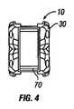
図4は、折り畳まれた位置で示される図1の拡張型椎体間スペーサの遠位端図である。 FIG. 4 is a distal end view of the expandable interbody spacer of FIG. 1 shown in a collapsed position.
図5は、図1の拡張型椎体間スペーサの分解図である。 FIG. 5 is an exploded view of the expandable interbody spacer of FIG.
図6は、拡張された位置で示される図1の拡張型椎体間スペーサの上面図である。 6 is a top view of the expandable interbody spacer of FIG. 1 shown in an expanded position.
図7は、拡張された位置で示される図1の拡張型椎体間スペーサの右側面図である。 7 is a right side view of the expandable interbody spacer of FIG. 1 shown in an expanded position.
図8は、拡張された位置で示される図1の拡張型椎体間スペーサの左側面図である。 8 is a left side view of the expandable interbody spacer of FIG. 1 shown in an expanded position.
図9は、拡張された位置で示される図1の拡張型椎体間スペーサの近位端図である。 FIG. 9 is a proximal end view of the expandable interbody spacer of FIG. 1 shown in an expanded position.
図10は、拡張された位置で示される図1の拡張型椎体間スペーサの遠位端図である。 FIG. 10 is a distal end view of the expandable interbody spacer of FIG. 1 shown in an expanded position.
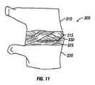
図11は、本開示の実施形態に係る、隣接する椎骨間の円板空間を示す図である。 FIG. 11 is a diagram illustrating a disc space between adjacent vertebrae according to an embodiment of the present disclosure.
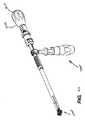
図12は、本開示の実施形態に係る、拡張型椎体間スペーサを挿入する工具の図である。 FIG. 12 is a view of a tool for inserting an expandable interbody spacer in accordance with an embodiment of the present disclosure;
図13は、本開示の実施形態に係る、図12の工具が、折り畳まれた位置の拡張型椎体間スペーサを円板空間に導入するのを示す図である。 FIG. 13 is a view showing the tool of FIG. 12 introducing the expandable interbody spacer in the collapsed position into the disc space, according to an embodiment of the present disclosure.
図14は、本開示の実施形態に係る、図12の工具が、椎体間スペーサを拡張させるのを示す図である。 FIG. 14 is an illustration of the tool of FIG. 12 expanding an interbody spacer in accordance with an embodiment of the present disclosure;
図15は、本開示の実施形態に係る、骨成長誘発材料を円板空間に導入する漏斗を示す図である。 FIG. 15 shows a funnel for introducing bone growth inducing material into the disc space, according to an embodiment of the present disclosure.
図16は、拡張型椎体間スペーサの別の実施形態の分解図である。 FIG. 16 is an exploded view of another embodiment of an expandable interbody spacer.
図17は、折り畳まれた位置で示される、拡張型椎体間スペーサの別の実施形態の上面図である。 FIG. 17 is a top view of another embodiment of an expandable interbody spacer, shown in a collapsed position.
図18は、拡張された位置で示される、図17の拡張型椎体間スペーサの上面図である。 18 is a top view of the expandable interbody spacer of FIG. 17 shown in an expanded position.
図19は、図17の拡張型椎体間スペーサの分解図である。 FIG. 19 is an exploded view of the expandable interbody spacer of FIG. 17;
図20は、図17の拡張型椎体間スペーサの接合アームのリンクの分解図である。 FIG. 20 is an exploded view of the links of the articulating arms of the expandable interbody spacer of FIG. 17;
図21は、折り畳まれた位置で示される拡張型椎体間スペーサの別の実施形態の上面図である。 FIG. 21 is a top view of another embodiment of an expandable interbody spacer shown in a folded position.
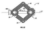
図22は、折り畳まれた位置で示される、図21の拡張型椎体間スペーサの上面図である。 22 is a top view of the expandable interbody spacer of FIG. 21 shown in a collapsed position.
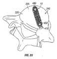
図23は、折り畳まれた位置にて円板空間に示される、図21の拡張型椎体間スペーサの図である。 FIG. 23 is a view of the expandable interbody spacer of FIG. 21 shown in the disc space in the collapsed position.
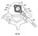
図24は、拡張された位置にて円板空間に示される、図21の拡張型椎体間スペーサの図である。 FIG. 24 is a view of the expandable interbody spacer of FIG. 21 shown in the disc space in the expanded position.
図25は、本開示の実施形態に係る、図21の拡張型椎体間スペーサと係合するのを示す工具の上面図である。 25 is a top view of a tool shown engaged with the expandable interbody spacer of FIG. 21 according to an embodiment of the present disclosure.
図26は、本開示の実施形態に係る、円板空間における図24の拡張型椎体間スペーサを拡張させている図24の工具を示す図である。 FIG. 26 is a view of the tool of FIG. 24 expanding the expandable interbody spacer of FIG. 24 in disc space according to an embodiment of the present disclosure;
図27Aは、本開示のさらなる実施形態に係る、拡張された位置での例示的な拡張型椎体間スペーサの等角図である。 FIG. 27A is an isometric view of an exemplary expandable interbody spacer in an expanded position according to a further embodiment of the present disclosure.
図27Bは、折り畳まれた位置での、図27Aの拡張型椎体間スペーサの等角図である。 27B is an isometric view of the expandable interbody spacer of FIG. 27A in a collapsed position.
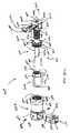
図28は、図27Aの拡張型椎体間スペーサの分解図である。 FIG. 28 is an exploded view of the expandable interbody spacer of FIG. 27A.
図29は、折り畳まれた位置にある、図27Aの拡張型椎体間スペーサの断面図を示す。 FIG. 29 shows a cross-sectional view of the expandable interbody spacer of FIG. 27A in a collapsed position.
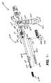
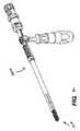
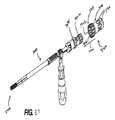
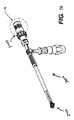
図30は、本開示の原理に係る、例示的な拡張型椎体間スペーサの実施形態を移植するための例示的な工具の実施形態を示す。 FIG. 30 illustrates an exemplary tool embodiment for implanting an exemplary expandable interbody spacer embodiment in accordance with the principles of the present disclosure.
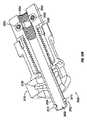
図31は、図30に示す工具の様々な構成要素の部分分解図を示す。 31 shows a partially exploded view of the various components of the tool shown in FIG.
図32Aは、図30の工具の近位部分の断面図を示す。 32A shows a cross-sectional view of the proximal portion of the tool of FIG.
図32Bは、アクチュエータ組立体の断面図を示す。 FIG. 32B shows a cross-sectional view of the actuator assembly.
図32Cは、アクチュエータ組立体の分解図を示す。 FIG. 32C shows an exploded view of the actuator assembly.
図33〜43は、図30の例示的な工具の構成要素及び例示的な椎体間スペーサとそれらとの相互作用の様々な図を示す。 33-43 show various views of the components of the exemplary tool of FIG. 30 and their interaction with the exemplary interbody spacers.
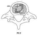
図44は、拡張型椎体間スペーサの例示的な実施形態の最終移植後構成を示す。 FIG. 44 shows a final post-implant configuration of an exemplary embodiment of an expandable interbody spacer.
図面全体にわたって、同様の参照番号は同様の特徴及び構造を指すと理解するものとする。 Like reference numerals are to be understood as referring to like features and structures throughout the drawings.
〔発明を実施するための形態〕
本開示の好ましい実施形態を、添付図面を参照して説明する。本発明の以下の詳細な説明は、全ての実施形態を図示する意図はない。本開示の好ましい実施形態を説明する中で、具体的な用語は明確性のために使用されている。しかしながら、本明細書に説明される実施形態は、そのように選択された具体的な用語に限定されことを意図するものではない。各具体的な要素は、同様の目的を実現するために同様の様態で動作する全ての技術的等価物を含むように理解されるものとする。[Mode for Carrying Out the Invention]
Preferred embodiments of the present disclosure will be described with reference to the accompanying drawings. The following detailed description of the invention is not intended to illustrate all embodiments. In describing preferred embodiments of the present disclosure, specific terms are used for clarity. However, the embodiments described herein are not intended to be limited to the specific terms so selected. Each specific element is to be understood as including all technical equivalents that operate in a similar manner to achieve a similar purpose.
本明細書で用いられる、用語「近位」は、移植手順中に、操作者または医療従事者の最も近くに設けられる装置または構成要素の部分を指し得る。逆に、用語「遠位」は、移植手順中に、近位部分とは反対側に設けられて、操作者または医療従事者の遠くに設けられる装置または構成要素の部分を指し得る。以下に記載するように、本明細書にて説明する拡張型椎体間スペーサの実施形態は、当該技術分野で知られるあらゆる任意の好適な進入法によって移植されてもよい。しかしながら、開示される実施形態はオフセット(例えば、20〜40度オフセット)後方進入を介して移植されてもよいことが企図される。したがって、方向付けの目的のみのために、移植されるときの装置の「近位」部分は、後方進入によって移植される場合は、患者に対して後方に設けられてもよい。 As used herein, the term "proximal" may refer to the portion of the device or component provided closest to the operator or healthcare professional during the implantation procedure. Conversely, the term "distal" may refer to that portion of the device or component that is provided opposite the proximal portion during implantation procedures and that is remote from the operator or healthcare worker. As described below, the expandable interbody spacer embodiments described herein may be implanted by any suitable approach known in the art. However, it is contemplated that the disclosed embodiments may be implanted via an offset (e.g., 20-40 degree offset) posterior approach. Thus, for orientation purposes only, the "proximal" portion of the device when implanted may be provided posterior to the patient when implanted by posterior approach.
図1〜10を参照すると、本開示の実施形態にしたがって拡張型椎体間スペーサ10が示されている。図示の実施形態では、拡張型椎体間スペーサ10は近位端20と遠位端30とを有する。拡張型椎体間スペーサ10は、スペーサ10の長手方向軸15の両側にそれぞれ位置する第1の接合アーム40及び第2の接合アーム50を備えていてもよい。第1及び第2の接合アーム40、50は、例えば、近位接続部材60によって、近位端20にて相互接続されていてもよい。第1及び第2の接合アーム40、50は、例えば、遠位接続部材70によって、遠位端30にて相互接続されていてもよい。拡張型椎体間スペーサ10の第1及び第2の接合アーム40、50は、チタン、ステンレス鋼、チタン合金、非チタン合金、高分子材料、プラスチック複合材、ポリエーテルエーテルケトン(「PEEK」)プラスチック材料、セラミック、弾性材料、及びそれらの組み合わせを含むいくつかの材料から作られていてもよい。拡張型椎体間スペーサ10は、手術部位に対して後部、前部、側部、または混合の進入法によって使用可能であるが、スペーサ10は特に後方進入と好適である。 Referring to FIGS. 1-10, an
第1の接合アーム40は近位端80と遠位端90とを有する。近位端80は近位接続部材60に枢動可能に連結されていてもよい。遠位端90は遠位接続部材70に枢動可能に連結されていてもよい。近位端80及び遠位端90と近位接続部材60及び遠位接続部材70とを枢動可能に連結するために、多種多様の様々な、例えばピン100などの任意の留め具を用いてもよい。別の実施形態(図示せず)では、接続はヒンジ接続であってもよい。図示するように、第1の接合アーム40は互いに枢動可能に連結される複数のリンクを備えていてもよい。図示の実施形態では、第1の接合アーム40は第1のリンク110、第2のリンク120、及び第3のリンク130を備える。スペーサ10が折り畳まれた位置にあるとき、第1のリンク110、第2のリンク120、及び第3のリンクは一般的に軸方向に並んでいてもよい。図示するように、第1のリンク110、第2のリンク120、及び第3のリンク130は端と端とで接続されてもよい。スペーサ10が折り畳まれた位置にあるとき、第1のリンク110、第2のリンク120、及び第3のリンク130は一般的に軸方向に並んでいてもよい。第1のリンク110及び第2のリンク120は枢動可能に連結されていてもよく、第2のリンク120及び第3のリンク130もまた回転可能に連結されていてもよい。例えば、ピン100などの任意の多種多様の様々な留め具を、リンク110、120、130を枢動可能に連結するのに用いてもよい。別の実施形態(図示せず)では、連結はヒンジ接続を介していてもよい。 The
図1、5〜7、9、及び10にて最もよく見えるように、第1の接合アーム40の上面140をリンク110、120、130によって画定してもよい。上面140は第1の接合アーム40に、隣接する椎体のうちの1つと係合することを可能とすべきである。いくつかの実施形態では、上面140は隣接する椎体を掴むのを補助するためにテクスチャリング150を含んでいてもよい。以下に限定されないが、テクスチャリング150は、歯、隆起、摩擦増加要素、竜骨、または掴みもしくは掛かり突起部を含むことができる。 The
図7、9、及び10で最もよく見えるように、第1の接合アーム40の下面160はリンク110、120、130によって画定されてもよい。下面160は、第1の接合アーム40が、隣接する椎体のうちの1つと係合することを可能とすべきである。いくつかの実施形態では、下面160は隣接する椎体を掴む補助としてテクスチャリング170を備えていてもよい。以下に限定されないが、テクスチャリング170は、歯、隆起、摩擦増加要素、竜骨、または掴みもしくは掛かり突起部を含むことができる。 As best seen in FIGS. 7, 9 and 10, the
第2の接合アーム50は近位端180と遠位端190とを有する。近位端180は遠位接続部材70と枢動可能に連結していてもよい。遠位端190は遠位接続部材70と枢動可能に連結していてもよい。近位端180及び遠位端190と近位接続部材60及び遠位接続部材70とを枢動可能に連結するために、例えばピン100などの多種多様な様々な留め具を用いてもよい。別の実施形態(図示せず)では、接続はヒンジ接続であってもよい。図示のように、第2の接合アーム50は互いに枢動可能に連結される複数のリンクを備えていてもよい。図示の実施形態では、第2の接合アーム50は第1のリンク200、第2のリンク210、及び第3のリンク220を備える。スペーサ10が折り畳まれた位置にあるとき、第1のリンク200、第2のリンク210、及び第3のリンク220は一般的に軸方向に並んでいてもよい。図示のように、第1のリンク200、第2のリンク210、及び第3のリンク220は端と端とで接続されていてもよい。第1のリンク200及び第2のリンク210は枢動可能に連結されていてもよく、第2のリンク210及び第3のリンク220もまた枢動的に連結されていてもよい。リンク200、210、220を枢動可能に連結するのに、ピン100などの多種多様な様々な留め具を用いてもよい。別の実施形態(図示せず)では、連結はヒンジ接続を介していてもよい。 The
図1、2、6、及び8〜10にて最もよく見えるように、第2の接合アーム50の上面230はリンク200、210、220によって画定されてもよい。上面230は、第2の接合アーム50が、隣接する椎体の1つに係合することを可能とすべきである。いくつかの実施形態では、上面230は隣接する椎体を掴む補助としてテクスチャリング240を備えていてもよい。以下に限定されないが、テクスチャリング240は、歯、隆起、摩擦増加要素、竜骨、または掴みもしくは掛かり突起部を含むことができる。 The
図8〜10で最もよく見えるように、第2の接合アーム50の下面250はリンク200、210、及び220によって画定されてもよい。下面250は、第2の接合アーム50が、隣接する椎体の1つと係合するのを可能とすべきである。いくつかの実施形態では、下面250は隣接する椎体を掴む補助としてテクスチャリング260を備えていてもよい。以下に限定されないが、テクスチャリング260は、歯、隆起、摩擦増加要素、竜骨、または掴みもしくは掛かり突起部を含むことができる。 As best seen in FIGS. 8-10, the
次に図3、5、及び9を参照すると、孔270は近位接続端60を通って延伸する。孔270はスペーサ10の長手方向軸12(図1を参照のこと)に一般的に平行に延伸してもよい。第1の接合アーム40及び第2の接合アーム50は、スペーサ10を軸方向に延伸する中空内側部分(図示せず)を画定してもよい。近位接続端60における孔270は、この中空内側部分と連通してもよい。図5で最もよく示されるように、遠位接続端70は開口部280を有していてもよい。図示するように、開口部280は内側を向き、遠位接続70まで延伸しなくてもよい。一実施形態では、開口部280は通常、孔270に挿入される工具(例えば、図12に示される工具340)が円板空間内へのスペーサ10の配置及び/またはスペーサ10の拡張のために開口部280にて受け入れられるように、近位接続端60内で孔270と並べられてもよい。 Referring now to FIGS. 3, 5 and 9, the
図1〜4は、拡張型椎体間スペーサ10を折り畳まれた位置で図示する。本実施形態によれば、拡張型椎体間スペーサ10は横方向に拡張して拡張位置にされてもよい。図6〜10は拡張型椎体間スペーサ10を拡張位置にて図示する。拡張位置では、第1のアーム40及び第2のアーム50は反対の位置で内側にそれぞれ折り畳まれている。例えば、第1のアーム40の近位端80及び遠位端90は、より近くなるように折り畳まれていてもよい。リンク110、120、130は第1のアーム40が内側に折り畳まれるときに互いに対して枢動すべきである。近位端80は近位接続端60で枢動すべきであり、遠位端90は遠位接続端70で枢動すべきである。さらなる例では、第2のアーム50の近位端180及び遠位端190もまた、一緒に折り畳まれてもよい。リンク200、210、220は、第2のアームが内側に折り畳まれるときに互いに対して枢動すべきである。近位端180は近位接続端60にて枢動すべきであり、遠位端190は遠位接続端70で枢動すべきである。拡張型椎体間スペーサ10は、拡張位置に配置された後、スペーサの使用後に拡張型椎体間スペーサ10が倒れないように、拡張位置で固定可能である。拡張型椎体間スペーサ10を固定するのに、例えばピンまたはその他の好適な係止機構を含む、任意の多種多様な様々な技術を用いてもよい。 1-4 illustrate the
図6に示すように、第1及び第2の接合アーム40、50は、拡張位置にあるときに内部空洞290を画定する。内部空洞290は、骨材料、骨成長因子、または骨形態形成タンパク質などの骨成長誘発材料で充填されてもよい。当業者によって認識されるように、骨成長誘発材料は骨材料の成長を誘発して、よって隣接する椎骨の融合を促進させる。 As shown in FIG. 6, the first and
拡張型椎体間スペーサ10は、様々な用途、様々な手順、脊椎の様々な領域への移植、または円板空間の大きさに適合するように、その大きさが調製されてもよい。例えば、拡張型椎体間スペーサ10は約8mm〜約22mm、及び代替的には約10mm〜約13mmの拡張前の幅W1(図1に示すとおり)を有していてもよい。さらなる例示によって、拡張型椎体間スペーサ10は約26mm〜約42mm、及び代替的には約16mm〜約32mmの範囲の幅W2(図6に示すとおり)を有していてもよい。拡張前または後の幅W1またはW2は、スペーサ10の長手方向軸12を横切って延伸する拡張型椎体間スペーサ10の幅を一般的に指すと理解すべきである。一般的に、拡張後の拡張型椎体間スペーサ10の幅W2は、拡張前の拡張型椎体間スペーサ10の幅W1よりも大きくあるべきである。
本実施形態によれば、拡張型椎体間スペーサ10は脊柱の損傷または疾患の治療で用いられてもよい。一実施形態では、拡張型椎体間スペーサ10は、椎間板が部分的または完全に取り除かれた、隣接する椎骨間の円板空間に挿入されてもよい。図11は、拡張型椎体間スペーサ10(例えば、図1〜10)が挿入され得る脊椎分節300を示す。脊椎分節300は、参照番号310及び320で識別される隣接する椎骨を含む。隣接する椎骨310、320のそれぞれは、対応する終板315、325を有する。円板空間330は、隣接する椎骨310、320の間の空間である。図12は、円板空間330に拡張型椎体間スペーサ10を挿入するのに用い得る工具340を図示する。工具340は、拡張型椎体間スペーサ10を連結するための細長端部分360を有するシャフト350を備える。細長端部分360は遠位先端370を有する。 According to this embodiment, the
図13及び14は、工具340を用いた円板空間330への拡張型椎体間スペーサ10の導入を図示する。図示目的で、図11に示される上側椎骨330は図13及び14からは取り除かれている。図示するように、スペーサ10は工具340に固定されてもよい。例えば、工具340の細長端部分360は、端部360の遠位先端370(例えば、図12を参照のこと)が遠位接続端70内の開口部280(例えば、図5を参照のこと)に固定されて、近位接続端60内の孔270(例えば、図5を参照のこと)を通して配置されてもよい。図13に示すように、工具340はスペーサ10を、アクセスカニューレ380を通して円板空間330内に導入してもよい。円板空間330内への導入後、スペーサ10は横に拡張されてもよい。本実施形態によれば、スペーサ10は第1のアーム40及び第2のアーム50を内側に折り畳むことで横方向に拡張可能である。横方向に拡張することで、スペーサ10は終板325と増加した表面積接触を有する。さらに、スペーサ10は骨端輪周りにより硬い骨を係合し得る。前に記載するように、拡張位置のときに内部空洞290をスペーサ10内に形成すべきである。次に、工具340をスペーサ10から外して、カニューレ380から取り外してもよい。図15に図示するように、次に漏斗390をカニューレ380の上に配置してもよい。そして骨成長誘発材料を、カニューレ380を通して内部空洞290に配置してもよい。スペーサ10が横方向に拡張されているため、内部空洞290は骨成長誘発材料を詰めるための望ましい空間量を有するはずである。 13 and 14 illustrate the introduction of the
図16は、代替の実施形態に係る拡張型椎体間スペーサ10を図示する。図示の実施形態では、拡張型椎体間スペーサ10は第1の接合アーム40及び第2の接合アーム50を備える。第1の接合アーム40は近位端80と遠位端90とを有する。第1の接合アーム40は、例えばピン100でその端と端とが接続される複数のリンク110、120、130を備える。第1の接合アーム40はさらに、それらの接続でリンク110、120、130の間で配置され得るワッシャ105(例えば、PEEKワッシャ)を備えていてもよい。第2の接合アーム50は近位端180と遠位端190とを有する。第2の接合アーム50は、例えばピン100でその端と端とが接続される複数のリンク200、210、220を備える。第2の接合アーム50はさらに、その接続でリンク200、210、220の間に配置され得るワッシャ105(例えば、PEEKワッシャ)を備えていてもよい。ワッシャ105はまた、それらの対応する接続にて第1のアーム40と近位接続部材60及び遠位接続部材70との間に配置されてもよい。ワッシャ105はまた、それらの対応する接続にて第2のアーム50と近位接続部材60及び遠位接続部材70との間に配置されてもよい。ワッシャ105は、スペーサ10が拡張されたインプラントの範囲全体にてその形を保持できるように摩擦を引き起こす締まりばめを有するべきである。 FIG. 16 illustrates an
近位端80、180は、図19に示すように、例えばピン100によって枢動可能に連結されてもよい。遠位端90、180もまた、図19に示すように、例えばピン100によって枢動可能に連結されてもよい。第1の接合アーム40は第1のリンク110及び第3のリンク130を備え、第1のリンク110と第3のリンク130は枢動可能に連結されている。図1〜10の第1の接合アーム40とは対照的に、
次に図17〜19を参照すると、本開示の別の実施形態にしたがって拡張型椎体間スペーサ10が図示されている。図示の実施形態では、拡張型椎体間スペーサ10は第1の接合アーム40及び第2の接合アーム50を備える。第1の接合アーム40は近位端80と遠位端90とを有する。第2の接合アーム50は近位端180と遠位端190とを有する。近位端80、180は、図19に示すように、例えばピン100によって枢動可能に連結されてもよい。遠位端90、180もまた、図19に示すように、例えばピン100によって枢動可能に連結されてもよい。第1の接合アーム40は第1のリンク110及び第3のリンク130を備え、第1のリンク110と第3のリンク130は枢動可能に連結している。図1〜10の第1の接合アーム40とは対照的に、第2のリンク120がない。図20によって示すように、第3のリンク130は第1の連結セグメント400と第2の連結セグメント410とを備えていてもよく、これらは例えばピン420によって互いに固定されてもよい。第1の連結セグメント400及び第2の連結セグメント410は溝形接続を有していてもよく、例えば第1の連結セグメント400における溝430が第2の連結セグメント410の凸部440を受けてもよい。第2の接合アームは第1のリンク200及び第3のリンク220を備え、第1のリンク200と第3のリンク220は枢動可能に連結される。図1〜10の第2の接合アーム50と対照的に、第2のリンク210がない。The
Referring now to FIGS. 17-19, an
本実施形態によれば、図17〜19の拡張型椎体間スペーサ10の横方向の拡張は、第1のアーム40及び第2のアーム50を内側に折り畳むことを含んでいてもよい。例えば、第1のアーム40の近位端80と遠位端90は一緒に折り畳まれてもよく、第2のアーム50の近位端180と遠位端190もまた、一緒に折り畳まれてもよい。 According to this embodiment, the lateral expansion of the
次に図21及び22を参照すると、本開示の別の実施形態にしたがって拡張型椎体間スペーサ10が図示されている。図示の実施形態では、拡張型椎体間スペーサ10は近位端20と遠位端30とを有する。拡張型椎体間スペーサ10は、スペーサ10の両側の長手方向軸12に位置する第1の接合アーム40及び第2の接合アーム50を備えていてもよい。図示するように、拡張型椎体間スペーサ10はさらに雌ねじ450を備えていてもよい。雌ねじ450は、ヘッド460、及びスペーサ10の長手方向軸12に一般的に平行に延伸し得る長尺体470を備えていてもよい。いくつかの実施形態では、雌ねじ450はスペーサ10の近位端20から遠位端30に延伸してもよい。一実施形態では、長尺体470は格納可能であってもよい。例えば、長尺体470は、図22に示すように、ヘッド460に格納されてもよい。 Referring now to FIGS. 21 and 22, an
図23及び24によって図示されるように、スペーサ10は円板空間330に導入されてもよく、その中でスペーサ10は横に拡張可能である。本実施形態によれば、スペーサ10は第1のアーム40と第2のアーム50とを内側に折り畳むことで横方向に拡張可能である。いくつかの実施形態では、長尺体470はヘッド460に格納されることで第1のアーム40と第2のアーム50とが内側に折り畳まれて、第1のアーム40と第2のアーム50が雌ねじ450の遠位端480に固定されてもよい。 As illustrated by FIGS. 23 and 24, the
図25は、本開示の実施形態にしたがって、図22及び23の拡張型椎体間スペーサ10への工具490の取り付けを示す。図示するように、工具490は、雌ねじ450のヘッド460に固定可能である取り付け端500を有していてもよい。図26に示すように、工具40はスペーサ10を円板空間330に導入するのに用いてもよく、スペーサ10は横方向に拡張可能である。 FIG. 25 illustrates attachment of the
次に図27A〜29を参照すると、本開示の態様に係る、拡張型椎体間スペーサ2700のさらなる実施形態の複数図が図示されている。拡張型椎体間スペーサ2700は、本明細書に記載される他の椎体間スペーサのいずれの1つ以上の特徴をも含んでいてもよい。例えば、スペーサ2700及びその構成要素はチタンからなっているが、当該技術に知られる任意の好適な生体適合性材料が用いられてもよい。 Referring now to FIGS. 27A-29, multiple views of a further embodiment of an
図27Aを参照すると、例えば、スペーサ2700は、他のものの他に、近位部分2702を含んでいてもよい。近位部分2702は実質的に円柱の部分2703を含んでいてもよい。円柱部分2703は完全な円柱形状または部分的な円柱形状を含んでいてもよい。さらに、円柱部分2703は通る内腔2704を画定してもよい。内腔2704の表面は、例えば、以下により詳細に記載されるねじ山2705等、1つ以上の形状特徴を含んでいてもよい。一実施形態では、円柱部分2703の側面は、以下により詳細に記載するように、工具3000による係合を容易にするための1つ以上の形状特徴2706を含んでいてもよい。形状特徴2706は、任意の好適な形状及び/または構成をも含んでいてもよい。一実施形態では、形状特徴2706は、円柱部分2703を画定する側壁に設けられる細長い切込みを含んでいてもよい。さらに、細長い切込みは実質的に垂直の方向に、側壁に延伸していてもよい。 Referring to FIG. 27A, for example, the
複数の片持ちレッジ2707が円柱部分2703の遠位部分から遠位に延伸してもよい。互いに向き合った関係で配置されること以外は、片持ちレッジ2707は実質的に互いに類似していてもよい。レッジ2707は当該技術に知られる任意の好適な構成、形状、及び/または大きさを含んでいてもよい。一実施形態では、レッジ2707はそれらの間に、スペーサ2700の複数のリンク(以下に記載のように)を受けるための空間2708を画定してもよい。レッジ2707の外表面(例えば、内及び外表面)は、本明細書に記載するように、隣接する椎体を掴む補助をするためのテクスチャリング150を備えていてもよい。外表面はまた、骨内部成長を促進するように構成されてもよい。例えば、一実施形態では、レッジ2707の外表面は多孔構造または、例えばヒドロキシアパタイトのコーティングを含んでいてもよい。レッジ2707の外端は、以下に記載の複数のリンクに対応する部分と嵌め合うように連結するための任意の構成をも含んでもよい。一実施形態では、レッジ2707の外端は、各レッジ2707に対して複数のリンクが枢動するのを容易にするために曲線状であってもよい。さらに、各レッジ2707は、以下により詳細に記載するように、枢動ピン2709を通して受ける1つ以上の開口部2707を含んでいてもよい。 A plurality of
引き続き図27A〜図29を参照すると、近位部分2702はリンク2710及び2712に、複数の枢動ピン2709を介して回転可能に連結されていてもよい。リンク2710及び2712は互いに実質的に類似していてもよい。実際に、例えば図27Aに図示するように、リンク2710及び2712は互いの鏡像として位置してもよい。よって、簡潔さの目的のために、リンク2710及び2712の類似する部分はまとめて説明される。リンク2710及び2712の近位部分2714は空間2708に受け入れられてもよい。リンク2710、2712の近位部分2714はレッジ2707の間に嵌まるように適切に構成及び寸法化されてもよい。さらに、各近位部分2714は枢動ピン2709を受け入れる貫通孔2716を含む。貫通孔2716は各リンク2710、2712の近位部分2714にて扇形の切り出しに設けられてもよい。 With continued reference to FIGS. 27A-29,
枢動ピン2709は、リンク2710及び2712を近位部分2702に動作的に連結するための、当該技術に知られる任意の好適な留め具を含んでいてもよい。一実施形態では、枢動ピン2709は、締まりばめまたは摩擦ばめを介して開口部2707及び貫通孔2716内に挿入ならびに保持されてもよい。 The
いくつかの実施形態では、リンク2710及び2712の1つまたは両方と近位部分2702との間の界面は、近位部分2702に対する所定位置にリンク2710及び2712の1つまたは両方を保持するために構成されてもよい。例えば、レッジ2707の端は、近位部分2702に対する所定位置に摩擦保持されるように、壁2717と相互作用してもよい。一実施形態では、壁2717は、例えば、丸められた突起、または他のレッジ2707の端が係合し得る好適な特徴などの隆起部分(図示せず)を含んでいてもよい。 In some embodiments, the interface between one or both of
リンク2710及び2712の上面及び内面もまた、上述の好適なテクスチャリング150を備えていてもよい。さらに、上面及び内面もまた、上述のとおり、骨内部成長を促進するように構成されてもよい。各リンク2710及び2712もまた、通る1つ以上の開口部2718を画定してもよい。開口部2718は当該技術に知られる任意の好適な構成をも含んでいてもよい。一実施形態では、開口部2718は実質的に長方形の構成を含んでいてもよい。他の実施形態では、開口部2718は他の形状を含んでいてもよい。一実施形態では、開口部2718は壁2717とは遠位に設けられてもよい。開口部2718は移植骨窓として構成されてもよく、開口部2718を通ってスペーサ2700の内部に骨内部成長を容易化させることを可能とする。開口部2718の端は、当該技術で知られるように、適切に傾き、面取られ、及び/または丸め得る。さらに、開口部2718はリンク2710及び2712それぞれの中央部分に一般的に設けられてもよい。 The upper and inner surfaces of
リンク2710、2712の遠位端部分は、本明細書に記載するように、別のリンクと動作的に連結されるように構成されてもよい。一実施形態では、リンク2710、2712の遠位端部分はそこを通る孔2720を含む雄ヒンジ2719を画定してもよい。孔2720は、以下に記載する、リンク2710、2712を隣接するリンクに回転可能に連結するための枢動ピン2709を受け入れるために、構成されてもよい。一実施形態では、ヒンジ2719に垂直の壁は、1つ以上の位置保持特徴2721を画定してもよい。以下に記載のように、位置保持特徴2721は、リンクを所定の位置に摩擦保持するように、隣接するリンク上の対応する特徴と相互作用するように構成されてもよい。 The distal end portions of the
近位部分2702に連結される端と反対のリンク2710、2712のそれぞれの端は、リンク2722及び2724と動作可能に連結されてもよい。リンク2722及び2724のそれぞれは互いに実質的に類似していてもよい。よって、当業者であれば、リンク2722またはリンク2724のいずれかが、他方のリンク2722またはリンク2724の特徴を含み得ると理解するであろう。リンク2722及び2724のそれぞれの近位端部分は、ヒンジ2719を受けるための窪み2725を画定してもよい。窪み2725は近位に延伸するアーム2725a及び2725bの対の間に設けられてもよい。各アーム2725a、2725bは実質的に互いに類似していてもよく、よって、効率上の目的で、1つのアーム2725aだけが取り上げられる。 The respective ends of the
アーム2725aは、当該技術に知られる任意の好適な形状及び/構成を含んでいてもよい。一実施形態では、アーム2725aの外表面はリンク2712または2710に対して回転するのを容易にするために丸められてもよい。アーム2725aの側面は、位置保持特徴2721を係合するための1つ以上の位置保持特徴2727を含んでいてもよい。使用中、リンク2724及び2712は互いに関連して回転してもよい。例えば、位置保持特徴2721及び2727は、リンク2724及び2712を所望の位置に保持するために、互いに摩擦的に係合してもよい。位置保持特徴2727は位置保持特徴2721と類似していてもよい。例えば、一実施形態では、位置保持特徴2727はアーム2725aの残る表面に対して隆起される突起であってもよい。
各リンク2722及び2724はまた、リンク2722及び2724の中央部分に一般的に設けられる1つ以上の開口部2718を含んでいてもよい。上述のように、開口部2718は各対応するリンク2722、2724を通って延伸するように構成されてもよく、骨内部成長を容易にするように構成されてもよい。開口部2718の1つ以上の端は、当該技術で知られるように、傾いていても、丸められても、及び/または面取られていてもよい。 Each
各リンク2722及び2724の遠位端は、複数の延伸部2729、2730を含んでいてもよい。延伸部2729、2730はリンク2722、2724の中央部分から離れて延伸するように構成されてもよく、その間の空間2732を画定するように構成されてもよい。空間2732はスペーサ2700の遠位構成要素を受けるように構成されてもよい。各延伸部2729、2730はその中に貫通孔2734を含んでいてもよい。貫通孔2734は、当該技術に知られる任意の好適な構成を含んでいてもよい。貫通孔2734は、以下により詳細に記載される遠位構成要素にリンク2722、2724を動作可能に連結するための対応する枢動ピン2709を受けるように構成されてもよい。 The distal end of each
延伸部2729、2730の1つまたは両方の内側を向いている表面は、対面するリンクの延伸部2729、2730の対応する表面と相互作用または係合するように構成されてもよい。例えば、図28に示すように、リンク2722、2724の1つの延伸部2729、2730の内側を向いている表面は、他のリンク2722、2724に設けられる延伸部の内側を向いている表面に設けられる対応する寸法に係合するように構成されてもよい複数の歯、窪み、突設物、切り欠きなどを含んでいてもよい。好ましい実施形態では、延伸部2729、2730の内側を向いている表面は複数の歯車の歯2736を含んでいてもよい。各延伸部2729、2730の歯車の歯2736は、単一面にて対応する1つのリンクの回転を他方に対して容易にするために、対面するリンクの歯車の歯2736を係合してもよい。 The inward facing surfaces of one or both of the
リンク2722及び2724のそれぞれは、遠位構成要素2740に動作可能に連結されてもよい。遠位構成要素2740は実質的に台形の構成を含んでいてもよい。つまり、遠位構成要素2740は遠位方向に、より大きな幅寸法からより小さな幅寸法に次第に細くなっていってもよい。図28を参照すると、遠位構成要素2740の近位面は、遠位構成要素2740を通る孔2744と連通する開口部2742を含んでいてもよい。例えば、図27Aに示すように、孔2744は遠位構成要素2740を完全に通って延伸する。孔2744は、当該技術に知られる任意の好適な構成を含んでもよい。一実施形態では、孔2744は、遠位部分により小さな直径に向けて細くなる実質的な円錐構成を含んでいてもよい。以下に記載するように、孔2744は移植工具と係合する雌ねじを含んでいてもよい。 Each of
遠位構成要素2740の上面及び内面は、延伸部2729、2730を受けるように構成されてもよい。よって、図28に最もよく示されるように、例えば、これらの表面は各リンク2722、2724の延伸部2729、2730を受けるための段部2746を含んでいてもよい。段部2746はその中に枢動ピン2709を受ける複数の開口部2748を、リンク2722、2724を遠位構成要素2740に回転可能に連結するために有していてもよい。当業者であれば、リンク2722、2724は遠位構成要素2740に、当該技術で知られる任意の好適な手段によって連結されてもよいと理解するであろう。遠位構成要素2740は段部2746から遠位に設けられる隆起部分を含んでいてもよい。隆起部分2750は、当該技術で知られる任意の好適な構成を含んでもよい。一実施形態では、隆起部分2750は、図27Aに示すように、遠位に細くなる構成を含んでいてもよい。図27Aにも示されるように、遠位構成要素2740は曲線状の外部構成を含んでいてもよい。 The top and inner surfaces of the
次に図28〜29を参照すると、スペーサ2700は、当該技術で知られる任意の好適な機構によって、拡張構成(図27Aに示される)にて維持されてもよい。上述のように、スペーサ2700は特定の位置保持特徴を含んでいてもよい。スペーサ2700の拡張構成をより永久的に保持するには、スペーサ2700は係止特徴2760を含んでいてもよい。当業者であれば、係止特徴2760が当該技術に知られる任意の好適な構成を含んでもよいことを理解するであろう。一実施形態では、係止特徴2760は実質的に円柱状の構成を含んでいてもよい。さらに、係止特徴2760は通る内腔2762を画定し得る。一実施形態では、内腔2762の壁は、工具(以下により詳細に記載する)に係止特徴2760を係合及び回転させる複数の寸法構成2762aを含んでいてよい。さらに、係止特徴2760は、図29に示すように、近位部分2702の内腔2704内に受けられるように構成及び寸法化されている。一実施形態では、係止特徴2760の外表面は内腔2704を係合するのに好適な寸法特徴を含んでいてもよい。内腔2704がねじ山2705を備える実施形態では、係止特徴2760の外表面は対応するねじ山2764を備えていてもよい。内腔2704におけるねじ山2705及びねじ山2764は、係止特徴が時計回りまたは反時計回りで回転されるか否かにかかわらず、係止特徴2760のみが内腔2704に引き抜かれることなく進入するように協働し得る。例えば、一実施形態では、ねじ山2705は内腔2704の開口部に対して短く終わってもよい。さらに、あるいは代替的に、1つ以上の隆起された円周上または部分的に円周上の突設物2705aは、内腔2704に対する開口部のほんの内側に形成されてもよい。かかる実施形態では、係止特徴2760は内腔2704内に、製造または組立プロセス中、及びユーザまたは医療従事者への出荷前に予め設けられてもよい。よって、ユーザまたは医療従事者は係止特徴2762を内腔2704の中にさらに進入させるためにでしか回転させられず、係止特徴2762を2704から取り外すことはできない。 Referring now to FIGS. 28-29,
図29を参照し、以下により詳細に記載するように、係止特徴2760は内腔2704内に進入されて円柱部分2703から空間2708に突出するように構成されてもよく、これは、図29に示すように、スペーサ2700が折り畳まれた構成にあるときにリンク2710及び2712の近位部分2714に占有されている。スペーサ2700が拡張位置にあるとき、近位部分2714は空間2708から外に動かされてもよい。したがって、係止特徴2760は回転されて結果的に内腔2704内に進入されて、係止特徴2760の遠位部分が内腔2708の外に、そして空間2704内に延伸するようにしてもよい。この位置では、係止特徴2762はリンク2710及び2712がそれらの折り畳まれた位置に戻るのを防止するように構成されてもよい。 With reference to FIG. 29, and as described in more detail below, the
スペーサ2700の構成要素は、上述されるものを含むがそれらに限定されない、当該技術に知られる任意の好適な材料から作製されてもよい。一実施形態では、スペーサ2700の1つ以上の構成要素がチタンから作製されてもよい。さらに、スペーサ2700の部分は、好適な治療、殺菌、麻酔、及び/または抗生の当該技術で知られる任意の好適なコーティングを含んでいてもよい。さらに上に示唆するように、スペーサ2700の部分はスペーサ2700の構造に骨内部成長を促進するように構成されてもよい。 The components of
次に図30〜31を参照すると、本明細書に記載の拡張型椎体間スペーサの様々な実施形態の、移植、取り外し、及びその他の操作に影響を与える工具3000の例示的な実施形態が示されている。工具3000は複数の構成要素を含んでいてもよく、それぞれが以下により詳細に記載される。当業者であれば、本明細書に記載する個別の構成要素のいずれもが、本開示の原理から逸脱することなく、他の構成要素と組み合わせることができる、または併せて省略可能であることを認識するであろう。 Referring now to FIGS. 30-31, an exemplary embodiment of a
工具3000はハンドル組立体3001を含んでいてもよい。ハンドル組立体は、操作者または医療従事者の手に持たれるように構成される細長構造3002を含んでもよい。このように、細長構造3002は当該技術で知られるように適切に構成及び寸法化されてもよい。いくつかの実施形態では、細長構造3002は、操作者によって掴まれる複数の寸法構成または特徴3004、例えば、突起、溝、凹み、隆起、ノブ、切り出し等を含んでいてもよい。さらに、細長構造3002はその長さにわたって一定の断面寸法を有していてもよく、あるいは細長構造3002はその長さにわたって変動する寸法を有していてもよい。さらに、細長構造3002は実質的に円形の断面構造を含んでいてもよい。しかしながら、いくつかの実施形態では、細長構造3002は、四角形、長方形、三角形等、任意の好適な断面構成を含んでいてもよい。
一般的に円柱状の延長部材3006は上面3005から離れるように延伸してもよい。図30〜31の目的のみのために、示される方向付けは動作中の方向付けであると推定される。よって、「上部」、「前部」、「近位」、「遠位」、「内部」、及び「後部」は、この方向付けに関連して用いられる。延長部材3006は、細長構造3002をホルダ3008に回転可能に接続するように作用する。 The generally
ホルダ3008は、当該技術に知られる任意の好適な構成を含んでいてもよい。一実施形態では、ホルダ3008は、以下により詳細に記載される挿入用フォークの近位部分を受けて摩擦係合するために、構成、形作られ、及び大きさを調整されてもよい。一実施形態では、例えば、ホルダ3008は実質的にU字の構成を有していてもよい。挿入用フォークはホルダ3008の「U」部分3008aを有して受け取られてもよい。U型ホルダ3008はベース部、及び2つの上方に延伸するアーム3009を有していてもよい。1つ以上のアーム3009が、挿入用フォークを摩擦係合及び保持するために提供されてもよい。例えば、寸法特徴は、へこみ、圧痕、窪み、開口、突設物、リブなどを含む。一実施形態では、各アーム3009の上部の内面にはリブ3010を含んでいてもよい。いくつかの実施形態では、U型ホルダ3008は挿入用フォークをホルダ3008内に(例えば、摩擦によって)保持する固定部材を含んでいてもよい。一実施形態では、保持部材は選択的に作動可能であってもよい。例えば、ホルダ3008のベース部は、挿入用フォークをホルダ3008に対して保持するために、挿入用フォークの一部を選択的に係合するセットねじ(図示せず)または他の類似する機構を含んでいてもよい。セットねじは第1の構成と第2の構成との間を移行するように構成されてもよい。第1の構成では、セットねじは実質的に完全に、またはホルダ3008のベース部内にて完全に受けられてもよい。第2の構成では、セットねじはベース部3008の外に進み、「U」部分3008aに進入してもよい。セットねじは、矢印Aによって示される方向に、細長構造3002をホルダ3008に対して回転させることで、第1と第2の構成との間で移行するように構成されてもよい。例えば、細長構造3002を回転させることは、セットねじの頭(図示せず)を回転させて、これによってセットねじをホルダ3008のベース部から外にねじり出す。 Holder 3008 may include any suitable configuration known to the art. In one embodiment, the holder 3008 may be configured, shaped and sized to receive and frictionally engage the proximal portion of the insertion fork described in more detail below. In one embodiment, for example, the holder 3008 may have a substantially U-shaped configuration. The fork for insertion may be received with the “U” portion 3008 a of the holder 3008. The U-shaped holder 3008 may have a base and two upwardly extending arms 3009. One or more arms 3009 may be provided to frictionally engage and hold the fork for insertion. For example, dimensional features include indentations, indentations, indentations, openings, protrusions, ribs, and the like. In one embodiment, the upper inner surface of each arm 3009 may include
引き続き図31を参照すると、挿入用フォークは一般的に細長い構造3012を含んでいてもよい。いくつかの実施形態では、細長構造3012はその中の1つ以上の内腔を画定してもよい。例えば、図32Aに示すように、細長構造3012は通る内腔3014を画定してもよい。細長構造3012は当該技術に知られる任意の好適な断面構造を含んでいてもよい。例えば、いくつかの実施形態では、細長構造3012は一般的に円筒の構造であってもよい。他の実施形態では、細長構造3012は実質的に長方形の断面構造を含んでいてもよい。さらなる実施形態では、細長構造3012の断面構造はその長さに沿って変動してもよい。例えば、図31に示すように、細長構造3012の遠位部分は実質的に四角形または長方形の切断構造を含んでいてもよく、細長構造3012の近位部分は実質的に円形の断面構成を含んでいてもよい。 Still referring to FIG. 31, the insertion fork may generally include an elongated structure 3012. In some embodiments, the elongated structure 3012 may define one or more lumens therein. For example, as shown in FIG. 32A, the elongated structure 3012 may define a
図31及び33を参照すると、細長構造3012の遠位部分はフォーク様構成に構成されてもよい。より具体的には、細長構造3012の遠位部分は2つのアーム3018と3020とを画定する垂直スリット3016を含んでいてもよい。2つのアーム3018、3020のみしか示されていないが、当業者であれば、本開示の原理に従ってより多いまたはより少ない数のアームも企図され得ることを理解するであろう。例えば、細長構造3012の遠位部分は単一のアームのみを含んでいてもよい。あるいは、細長構造3012は垂直面に設けられる2つの長手方向のスリットを含み得て、結果的に4つのアームを生成してもよい(図示せず)。1つ以上の細長構造3012の構成、スリット3016の構成、及び細長構造3012の材料特性の結果として、アーム3018及び3020は弾力性または他のバネ様特徴を示してもよい。例えば、アーム3018及び3020は互いから離れるように付勢されてもよい。別の実施形態では、アーム3018及び3020は互いに向かって付勢されてもよい。 Referring to FIGS. 31 and 33, the distal portion of elongated structure 3012 may be configured in a fork-like configuration. More specifically, the distal portion of elongated structure 3012 may include a
アーム3018及び3020は互いに実質的に類似していてもよい。したがって、効率の目的のために、アーム3020の特徴のみを説明する。当業者であれば、アーム3018はアーム3020の1つ以上の特徴を含み得ることを理解するであろう。具体的に図33を参照して、アーム3020の遠位端3022は、特徴2706を介してスペーサ2700の近位部分2702と解放可能に係合するように構成していてもよい。具体的には、アーム3020の遠位端3022は、特徴2706内で受けられるように構成及び形作られた突出部3024を含んでいてもよい。例えば、図33に示すように、突出部3024は互いに向かって延伸するように構成されてもよい。いくつかの実施形態では、特徴2706は突出部を含んでいてもよく、アーム3020の遠位端3022は突出部と解放可能に係合するための切り欠きまたは他の窪みを含んでいてもよい。さらに、突出部3024に近位のアーム3020の遠位端部分は、アーム3020をアーム3018に向かって、及びその逆に付勢するのを補助するために構成される1つ以上の寸法特徴を含んでいてもよい。より具体的には、アーム3020の外表面はリブ3026を含んでいてもよく、これはアーム3020をアーム3018に向かって付勢するためにスリーブ3030によって係合されてもよい。リブ3026は当該技術に知られる任意の好適な構成を含んでいてもよい。例えば、一実施形態では、リブは細長構造3012の長手方向軸を一般的に横切って延伸してもよい。いくつかの実施形態では、リブ3026の近位部分はアーム3020の残りの外表面に平滑に移行するように構成されてもよい。つまり、リブ3026の近位部分は細くなっているか一般的にランプ様の構造を含んでいてもよい。さらに、アーム3020には1つのリブ3026のみが示されているが、当業者であれば任意の好適な数のリブ3026が提供され得ることを理解するであろう。さらに、リブ3026は、アーム3020をアーム3018(及びその逆)に動かすのに必要な移動の量と相互関係にある高さ寸法を含み、スペーサ2700を効果的に係合する。
新たに図31及び図32A〜Bを参照すると、細長構造3012の近位端部分3013は以下のように構成される。一実施形態では、近位端部分3013は、細長構造3012の近位端から細長構造3012上のノブ3032からちょうど近接する位置まで延伸し得る水平スリット3028を含んでいてもよい。スリット3028は2つのアーム3028a、3028bを画定してもよく、互いから離れるか向かって付勢されるかのいずれかで構成されてもよい。各アーム3028a、3028bの近位端は挿入用フォークをアクチュエータ組立体に固定する補助をするために構成されてもよく、これは以下により具体的に記載される。実施形態では、少なくとも1つのアーム3028a、3028bの近位端は、隆起フランジ3027を含んでいてもよい。 Referring again to FIGS. 31 and 32A-B, the
上に示唆するように、細長構造3012はその上に設けられるノブ3032を含んでいてもよい。ノブ3032は任意の好適な構成を含んでいてもよい。一実施形態では、ノブ3032はスリット3028より遠位に設けられてもよい。ノブ3032の外表面は、ホルダ3008内にノブ3032を固定するための好適な寸法特徴を含んでいてもよい。例えば、ノブ3032の外表面は複数のこぶ、へこみ、窪み、及び/または突出部を含み得る。一実施形態では、ノブ3032はその上に設けられる複数のチャネル3031を含んでいてもよい。チャネル3031は、ホルダ3008にノブ3032を固定するのを容易にするための少なくとも1つのリブ3010を受けるように構成される。いくつかの実施形態では、細長構造3012はホルダ3008に対する細長構造3012の長手方向動作を制限するための機構を含んでいてもよい。例えば、細長構造3012は、アーム3009またはU型ホルダ3008のベース部のうちの1つに当接するように放射状に延伸するフランジ3033を含んでいてもよく、細長構造3012がハンドル3001に対して近位的に動くのを防ぐ。さらに、細長構造3012はその外表面に設けられる複数のねじ山3029を含んでいてもよい。一実施形態では、ねじ山3029はスリット3016の近位であるがフランジ3033の遠位に設けられてもよい。図31に示すように、ねじ山3029はスリット3016よりもフランジ3033の実質的に近くに設けられてもよい。 As alluded to above, the elongated structure 3012 may include a knob 3032 provided thereon. The knob 3032 may include any suitable configuration. In one embodiment, the knob 3032 may be provided distal to the
細長構造3012は、スリーブ3030の内腔3030a内に受けられるように構成される。スリーブ3030は当該技術に知られる任意の好適な構成を含んでいてもよい。例えば、スリーブ3030は一般的に細長構造3012の外周に対応する構成を含んでいてもよい。より具体的には、スリーブ3030は実質的に長方形の断面構造を有する遠位部分、及び実質的に円形の断面構造を有する近位部分を含んでいてもよい。スリーブ3030内の内腔3030aは同様に構成されてもよい。つまり、内腔3030aは細長構造3012の外周に対応する構成を含んでいてもよい。つまり、内腔3030aは実質的に長方形の断面構造を有する遠位部分、及び実質的に円形の断面構造を有する近位部分を含んでいてもよい。内腔3030aの近位部分は、内腔3030aの遠位部分での同様の幅寸法よりも大きい幅寸法を含んでいてもよい。さらに、内腔3030aの遠位端はアーム3018及び3020を互いに向かうように付勢して、本明細書に記載するように、スペーサ2700を係合し得るように構成されてもよい。さらに、一実施形態では、スリーブ3030は首部3034及びその近位端で近位縁3036を有する実質的に細長い中空部材であってもよい。当業者であれば、縁3036の代わりに、本開示の原理内にて任意の好適な寸法構成を用いてもよいように理解するであろう。 The elongated structure 3012 is configured to be received within the lumen 3030 a of the
細長構造3012上に受けられる前に、スリーブ3030の近位部分は挿入用ノブ3038に動作可能に連結されてもよい。挿入用ノブ3038は当該技術に知られる任意の好適なノブであってもよく、任意の好適な構成を含んでいてもよい。一実施形態では、ノブ3038は一般的に円柱状の構成を含んでいてもよい。しかしながら、本開示の原理にしたがって任意の好適な構成を用いてもよい。ノブ3038は、少なくとも1つの内腔3040を含んでいてもよい。内腔3040はノブ3038を完全に、または部分的に通って延伸してもよい。内腔3040の内表面の遠位部分は、縁3036と相互作用して挿入ノブ3038をスリーブ3030に保持するための少なくとも1つの寸法特徴3042を含んでいてもよい。一実施形態では、寸法特徴3042は、その中で縁3036を受けるように構成される周縁チャネルを含んでいてもよい。次に図32Aを参照すると、内腔3040は細長構造3012上でねじ山3029と協働するための複数のねじ山3044を含んでいてもよい。図示の実施形態ではねじ山3044が内腔3040の近位部分で設けられているように図示しているが、ねじ山3044は内腔3040のいずれの部分にも設けられてもよい。例えば、一実施形態では、ねじ山3044は内腔3040の中間点からその近位端まで延伸してもよい。 The proximal portion of the
次に図31〜32Cを参照して、アクチュエータ組立体3050を説明する。アクチュエータ組立体3050は、以下により詳細に記載するように、動作可能に共に連結されてスペーサ2700を拡張するのを容易にするために動作可能である複数の構成要素を含んでいてもよい。複数の構成要素は個別に説明されるが、当業者であれば、本開示の原理から逸脱することなく、説明される構成要素のいずれもが1つ以上の他の構成要素と組み合わせ可能、及び/または併せて排除可能である理解するであろう。 The
アクチュエータ組立体3050は中央部分3052を含んでいてもよく、これは近位頭3054及びそこから延伸する細長管状部材3056を含んでいてもよい。中央部分3052は内腔3058を画定してもよい。内腔3058は中央部分3052の中を完全に延伸し通してもよい。内腔3058は当該技術に知られる任意の好適な構成を含んでいてもよい。例えば、示されるように、内腔3058は実質的に円形の断面構造を含んでいてもよい。一実施形態では、近位端3054はその中で係止タブ3062を受けるチャネル3060を含んでいてもよく、これは以下でより詳細に記載する。チャネル3060は任意の好適な構成を含んでいてもよく、係止タブ3062に対応して寸法化及び形状化されてもよい。さらに、チャネル3060は、図32Bに示すように、内腔3058を横断するように構成されてもよい。さらに、内腔3058の一部は複数のねじ山3064を含んでいてもよい。ねじ山3064は内腔3058の任意の部分に沿って設けられてもよい。例えば、図示される実施形態では、ねじ山3064は内腔3058の近位部分のみに沿って設けられてもよい。ねじ山3064はチャネル3060の両側に、内腔3058に設けられてもよい。ねじ山3064は内腔3058の最も近位の端まで延伸してもよい。 The
外的には、近位ヘッド3054は任意の好適な構成を含んでいてもよい。図示の実施形態では、例えば、近位ヘッド3054は実質的に平面の近位端面3066を含んでいてもよい。端面3066は内腔3058と連通する開口部3067を含んでいてもよい。さらに、端面3066はその中に保持ピン3069を受ける第2の開口部3068を含んでいてもよい。開口部3068は開口部3067よりも小さい直径を含む。以下に記載されるように、保持ピン3067はチャネル3060にタブ3062を保持するために開口部3068に設けられてもよい。近位ヘッド3054は、一般的に円形の断面構成を含んでいてもよい。しかしながら、一実施形態では、近位ヘッド3054は実質的に平面の上面3070及び内面(図示せず)を含んでいてもよい。図32Cに図示するように、平面上面3070は、その中にタブ3062を受けるために、チャネル3060と連通する開口部3071を含んでいてもよい。引き続き図32B〜32Cを参照すると、中央部分3052は当該技術に知られる任意の好適な外形構成を含んでいてもよい。一実施形態では、中央部分3052は実質的に均一の外形構成を含んでいてもよい。図示の実施形態では、中央部分3052は段3072を含んでいてもよい。段3072は中央部分3052の長さに沿ったいずれの部分に位置してもよい。一実施形態では、段3072は中央部分3052の中間点に位置してもよい。段3052は任意の好適な構成を含んでいてもよい。例えば、段3052は中央部分3052の比較的小さな直径の遠位部分3052aと中央部分3052の比較的大きな直径近位部分3052bとの間の界面であってもよい。例えば、図32Cに示すように、段3072はいくつかの実施形態では傾斜面を含んでいてもよい。さらに、近位部分3052bの一部がその上にスリーブ部材3076を受けるように構成されてもよい。したがって、近位部分3052bは1つ以上の好適な寸法構成、例えば、以下により具体的に記載するように、スリーブ部材3076内で対応するねじ山3077を用いて桶を作るためのねじ山3074を含んでいてもよい。ねじ山3074は近位部分3052bの任意の部分に沿って延伸してもよい。例えば、ねじ山3074は近位部分3052bの実質的に全体、またはその一部のみに沿って延伸してもよい。 Externally, the
遠位部分3052は、アーム3028a及び3028bによって画定される内腔内で受けられるように、構成、大きさ調整、及び寸法化されていてもよい。一実施形態では、遠位部分3052は、アーム3028a、3028bによって画定される内腔の直径(または幅寸法)よりも大きい直径(または管状でない場合は、幅寸法)を含み、アーム3028a、3028bを、遠位部分3052をその間に受けるときに広げられるようにしてもよい。このようにして、遠位部分3052は遠位部分3052に作用するアーム3028a、3028bの本来の弾性特性によって摩擦保持されてもよい。アーム3028a、3028bによって画定される内腔内に遠位部分3052を方向付けて誘導するのを容易にするために、遠位部分3052は、スリット3028内に摺動可能に受けられるように構成されてもよい1つ以上の突出部3075を含んでいてもよい。 The
上述のように、開口部3071及びチャネル3060は、その中にアクチュエータ3050の内腔3058内の工具を受ける係止タブ3062を受けるように構成されてもよい。タブ3062は、当該技術に知られる任意の好適な構成を含んでいてもよい。一実施形態では、タブ3062はチャネル3060の外の方向に、1つ以上のバネまたはバネ様部材3063によって弾性的に付勢されてもよい。さらに、タブ3062は、上記の保持ピン3069によってチャネル3060内に保持されてもよい。タブ3062はさらに、通る通路3062aを画定してもよい。通路3062aは、当該技術に周知の任意の構成を含んでいてもよい。以下に記載するように、通路3062aは、ねじシャフトをアクチュエータ組立体3050に保持するために、ねじシャフト3200のチャネル3206を係合するように構成されてもよい(例えば、1つ以上の突出部を含んでいてもよい)。 As mentioned above, the
スリーブ3076は、通る内腔3078を画定する一般的に円柱状の部材を含んでいてもよい。スリーブ3076は、当該技術に知られる任意の好適な構成を含んでいてもよい。一実施形態では、スリーブ3076は一般的に円形の断面構成を含んでいてもよい。しかしながら、スリーブ3076は任意の好適な断面構成を含んでいてもよい。さらに、スリーブ3076の遠位端は一般的に先細構成を含んでいてもよい。内腔3078は一般的に円形の断面構成を含んでいてもよく、その中に近位部分3052bを受けるように構成されてもよい。実際に、上に示唆されるとおり、内腔3078は、スリーブ3076を中央部分3052上に保持するために、ねじ山3074と結合するように構成される複数のねじ山3077を含んでいてもよい。ねじ山3077は内腔3078の任意の好適な部分に沿って延伸してもよい。一実施形態では、例えば、ねじ山は内腔3078の全体にわたって延伸してもよい。別の実施形態では、ねじ山3077は内腔3078の一部のみに延伸してもよい。 The
スリーブ3076の全体的な最大直径は、近位ヘッド3054の直径または幅よりも少なくてもよい。さらに、スリーブ3076は、スリーブ3076の比較的大きな直径の遠位部分3076bとスリーブ3076の比較的小さな直径の近位部分3076aとの間の界面を画定する段3079を含んでいてもよい。段3079は、スリーブ3076に沿って任意の好適な位置に設けられてもよい。さらに、スリーブ3076はその近位端から遠位に延伸する1つ以上の長手方向溝3080を含んでいてもよい。溝3080はその中にロッド3081を受けるように構成されてもよく、これは以下により詳細に記載されるように、スリーブ3076がアクチュエータ3050の筐体3090内で回転するのを防止するように構成されてもよい。 The overall maximum diameter of the
ワッシャ3082は、図32Bに示されるように、近位部分3076aに摩擦保持されるように構成されてもよい。ワッシャ3082は、通る内腔3084を画定する一般的に円柱状の構成を含んでいてもよい。さらに、ワッシャ3082は、近位ヘッド3054の遠位面に当接するように構成される近位レッジ3085を画定するように構成されてもよい。ワッシャ3082はまた、その上に筐体3090を固定するための複数の雄ねじ3086を備えていてもよい。 The
筐体3090は、通る内腔3092を画定する一般的に円柱状の構造を含んでいてもよい。内腔3092は、当該技術に知られる任意の好適な構成を含んでいてもよい。例えば、内腔3092は一般的に円形の断面構成を含んでいてもよい。しかしながら、本開示の原理内にて任意の好適な断面構成を用いてもよい。内腔3092が円形の断面構成を含む実施形態では、内腔3092はその長さにわたって一般的に一定の直径を、または内腔3092の長さにわたって変動する直径を含んでいてもよい。例えば、内腔3092の近位部分はカウンターボアを含んでいてもよく、したがって内腔3092の残りよりも大きな直径を含んでいてもよい。内腔3092の近位部分はまた、その上に筐体3090を保持するために、ワッシャ3082のねじ山3086をねじで係合するねじ山3093を含んでいてもよい。ねじ山3093は内腔3092の任意の好適な部分に沿って延伸していてもよい。内腔3092の壁は1つ以上の溝3094を含んでいてもよく、これは溝3080と対応していてもよく、ロッド3081を受けるように構成される。ロッド3081、溝3904、及び溝3080は協働して、スリーブ3076が筐体3090内で回転するのを防止する。さらに、筐体3090は、例えば、PEEKを含む、当該技術で知られる任意の好適な生体適合材料からなっていてもよい。 The
外的に、筐体3090は当該技術に知られる任意の好適な構成を含んでいてもよい。図示の実施形態では、筐体3090は隆起近位部分3095を含んでいてもよい。近位部分3095は任意の好適な構成を含んでいてもよい。一実施形態では、近位部分3095は、適切に構成された工具によって係合されるための六角形の構成(例えば、六角形の断面構成)を含んでいてもよい。同様に、近位部分3095は、工具(以下に記載する)を近位部分3095上に保持するのを補助するように構成される1つ以上の寸法特徴3096を含んでいてもよい。寸法特徴3096は、複数の凹み、突起、窪み、チャネル、などを含んでいてもよい。筐体3090はさらに、隆起遠位部分3097を含んでいてもよい。隆起遠位部分3097は、筐体3090を通るチャネル3098を画定してもよい。チャネル3098は任意の好適な構成を含んでいてもよい。例えば、一実施形態では、チャネル3098は内腔3092の長手方向軸に実質的に垂直の方向に延伸してもよい。チャネル3098は、その中に摺動可能にキャッチ3100を受けるように構成されてもよい。さらに、隆起遠位部分3097は、その中に留め具3099aを受ける1つ以上の開口部3099を含んでいてもよい。留め具3099が、例えば、ねじなどのねじ留め具を含む実施形態では、開口部3099は対応するねじ山を含んでいてもよい。 Externally,
キャッチ3100は任意の好適な構成を含んでいてもよく、チャネル3098内にて受けられるように寸法化及び形作られてもよい。キャッチ3100は、例えばPEEKを含む、当該技術に知られる任意の好適な材料からなっていてもよい。一実施形態では、キャッチ3100は実質的に長方形の構成を含んでいてもよい。図31Cに示すように、キャッチ3100の側面3102は、キャッチ3100の外形輪郭が、キャッチ3100がチャネル3098内で受けられたときに隆起遠位部分3097に対応し得るように、半径化または曲線化されていてもよい。さらに、キャッチ3100の上面3104及び/または内面は、開口部3099に対応する1つ以上の開口部を含んでいてもよい。図32Cに示すように、開口部3104は任意の好適な構成を含んでいてもよい。例えば、開口部3104は実質的に細長い構成を含んでいてもよく、留め具3099aは開口部3104に摺動可能に設けられてもよい。結果的に、キャッチ3100は、留め具3099が開口部3104に設けられるときに、係合が外れることなくチャネル3098に対して前後に摺動するように構成されてもよい。さらに、キャッチ3100は、通るフランジ3027(図31に示す挿入用フォークの近位端で)及び/または遠位部分3052aを受けるために、通る通路3106を画定してもよい。通路3106は、当該技術に知られる任意の好適な構成を含んでいてもよい。一実施形態では、通路3106の壁は、フランジ3027を係合するように構成される周縁チャネル3108(図32Bに示す)を画定してもよい。周縁チャネル3108は通路3106の周り全体、または通路3106の部分的な周りに設けられてもよい。 The
次に図34〜44を参照して、工具3000の動作方法、及びスペーサ2700の例示的な実施形態を移植するためのその様々な構成要素を説明する。図34に示すように、スリーブ3030は、アーム3018、3020を互いに押し合って突出部3024が特徴2706と係合してスペーサ2700を工具3000に固定し得るように、遠位的に進行されてもよい。スリーブ3030は、ノブ3038を細長構造3012に対して回転することで遠位に移動されてもよい。ねじ山3044及び3029を介して連結した結果、ノブ3038を細長構造3012に対して回転させることは、ノブ3038とスリーブ3030とが細長構造3012に対して長手方向に移動する結果をもたらす場合がある。 34-44, the method of operation of the
一度スペーサ2700が工具3000に固定されると、スペーサ2700は患者内への移植の準備が整う。上述のように、スペーサ2700は、患者内の椎体間円板空間に、当該技術の任意の好適な手順を介して送達され得る。例えば、一実施形態では、スペーサは前部進入を介して送達される。別の実施形態では、スペーサは後方進入を介して送達してもよい。さらに、進入角度は当該技術に知られる任意の角度であってもよい。例えば、スペーサ2700は後方進入を介して、患者の中心線から20〜40度外れた角度で工具3000によって送達されてもよい。 Once the
一度スペーサ2700が挿入用フォークの遠位端に固定されると、ねじシャフト3200はアクチュエータ組立体3050の近位端に挿入されてスリーブ3030の遠位端まで抜け、近位部分2702の内腔2705内に入り、そしてスペーサ2700の遠位構成要素2740の内腔2744に挿入される。図35を参照すると、ねじシャフト3200は任意の好適な構成を含んでいてもよい。一実施形態では、ねじシャフト3200は細長部材3202を含んでいてもよい。細長部材3202は任意の好適な構成を含んでいてもよい。実施形態では、細長部材3202は一般的に円柱状の構成を含んでいてもよい。例えば、細長部材3202は一般的に円形の断面構成を含んでいてもよい。さらに、細長部材3202はその遠位端に向かって徐々に細くなるように構成されてもよい。つまり、細長部材3202の近位部分は細長部材3202の遠位部分より比較的大きな直径を含んでいてもよい。 Once the
一実施形態では、細長部材3202の遠位部分、例えば遠位端は、スペーサ2700の遠位構成要素2740を係合するように構成されてもよい。例えば、細長部材3202の遠位部分は、遠位構成要素2740の内腔2744内に設けられる寸法構成と協働するように構成される1つ以上の寸法構成を含んでいてもよい。内腔2744がねじを含み得る実施形態では、例えば、細長部材3202の遠位部分もまた、ねじ3208を含んでいてもよい。 In one embodiment, the distal portion, eg, the distal end, of the elongated member 3202 may be configured to engage the
細長部材3202の近位端は、作動部材3204を含んでいてもよい。作動部材3204は、当該技術に知られる任意の好適な構成を含んでいてもよい。一実施形態では、作動部材3204は細長部材3202の近位部分に取り外し可能に連結されてもよい。別の実施形態では、作動部材3204は細長部材3202と一体的に形成されてもよい。作動部材3204はいくつかの実施形態でノブまたはハンドルを含んでいてもよい。したがって、作動部材3204は1つ以上の寸法構成3210を、操作者による掴みを容易にするために含んでいてもよい。寸法構成3210は、隆起、チャネル、突設物、突出物、凹み、突起、窪み、表面テクスチャリングなどを含み得る。さらに、細長部材3202はチャネル3206を含んでいてもよい。チャネル3206は細長部材3202に沿って任意の好適な位置に設けられてもよい。一実施形態では、チャネル3206は、遠位端よりも細長部材3202の近位端に近くに設けられてもよい。シャネル3206は、細長部材3202の直接隣接する部分よりも比較的小さい直径を含む細長部材3202の部分によって画定されてもよい。チャネル3206は、通路3062aによって係合されるのに好適な細長部材3202上の位置に位置決めされてもよい(図32Cに示すとおり)。さらに、作動部材3204は、以下にさらに記載するように、スペーサ2700の拡張の度合を示すための1つ以上のマーキング3212(図38Aに示すとおり)を含んでいてもよい。マーキング3212は当該技術に知られる任意の好適なマーキングを含んでいてもよく、スペーサ2700の拡張割合に対応する数値を含んでいてもよい。 The proximal end of the elongated member 3202 may include an
次に図36を参照すると、工具3000はスペーサ2700に固定されていてもよく、ねじシャフト3200は工具3000内で受けられてもよい。工具3000は次に、患者内にスペーサ2700の移植をもたらすために患者に挿入されてもよい。しかしながら、いくつかの実施形態では、工具3000及びスペーサ2700は、ねじシャフト3200が工具3000に挿入されてスペーサ2700に固定されるときには既に患者内に位置付けられていてもよい。 Referring now to FIG. 36,
次に図37を参照すると、拡張型六角形キャップ3700を工具3000及び作動部材3204の近位端上に位置付けてもよい。一実施形態では、六角形キャップ3700は、その中で内腔3702を画定する一般的に円柱状の部材を含んでいてもよい。内腔3702は六角形キャップ3700を完全に通って延伸してもよく、または六角形キャップ3700が閉近位端を含んで出口がなくてもよい。六角形キャップ3700の遠位端部分3704は、近位部分3095上で受けられて係合するように構成されてもよい。したがって、遠位端部分3704は近位部分3095に対応する構成を含んでいてもよい。例えば、遠位端部分3704は六角形の工具として形作られてもよい。さらに、遠位部分3704内の内腔3702の内表面は、近位部分3095上の寸法特性3096を係合するように構成される、1つ以上の寸法特性3706を含んでいてもよい。一実施形態では、寸法特性3706は複数の突起を含んでいてもよく、一方で寸法特性3096は複数の窪みを含んでいてもよく、または逆であってもよい。さらに、図37に示すように、遠位端部分3704は六角形キャップ3700の近位部分3708よりも比較的大きい直径を含んでいてもよい。 Referring now to FIG. 37, expandable
さらに、六角形キャップ3700の近位部分3708は、その周りに放射状に設けられる複数の窓または開口部3710を含んでいてもよい。開口部3710は当該技術に知られる任意の好適な構成を含んでいてもよく、作動部材3204上に設けられるマーキング3212の可視化を容易にし得る。近位部分3708は所望の任意の好適な数の開口部を含んでいてもよい。 Additionally, the proximal portion 3708 of the
動作中、及び患者内に(例えば、六角形キャップ3700を矢印3712の方向に動かすことで)スペーサ2700が適切に位置付けられている間、遠位端部分3704がアクチュエータ組立体の近位部分3095を係合して、作動部材3204が開口部3710を通して操作者に可視となってもよいように、六角形キャップ3700は工具3000の近位端上に位置付けられてもよい。次に、操作者は六角形キャップ3700を、得られる場合はスペーサ2700を所望の拡張量まで拡張させてもよい。六角形キャップ3700を回転させることは、遠位端部分3704との係合を介した近位部分3095(及び、ひいては、筐体3090)の回転を引き起こす。上述のアクチュエータ組立体3050の様々な構成要素及びそれらの接続の結果として、筐体3090が回転しているときにスリーブ3076もまた、ロッド3081を介して筐体3090に対して固定されているために回転される。結果的に、スリーブ3076と筐体3090は、中央部分3052に対して長手方向に並進する。さらに、近位端フランジ3027が筐体3090にキャッチ3100を介して固定されるため、挿入用フォーク全体もまた、六角形キャップ3700が回転されると中央部分3052に対して長手方向に並進する。及び、ねじシャフト3200が中央部分3052にキャッチ3206ならびにタブ3062を介して固定されるため、スペーサ2700の遠位構成要素にねじ込まれる遠位ねじ3208は、スペーサ2700の近位部分2702に対して、六角形キャップ3700が回転されるときに挿入用フォークが動いている間に動いてもよい。かかる挿入用フォークの遠位端とねじシャフト3200との間の相対動作は、近位部分2702を遠位構成要素2740に向かって動かして、スペーサの様々な構成要素として、図27Bに図示される位置から図27Aに図示される位置、または任意の好適な所望の中間位置に回転させながら、スペーサ2700の拡張をもたらす。上に示唆するように、例えば、作動部材3054に対する筐体3090の移動度合は、スペーサ2700の拡張度合に対応していてもよい。したがって、作動部材3054はスペーサ2700の拡張の度合を決定するのに操作者を補助する複数のマーキングを含んでいてもよい。 During operation, and while the
スペーサ2700の所望の拡張が得られた後、及びスペーサ2700が患者内にて適切に位置付けられた後に、六角形キャップ3700は取り外されてもよい。続いて、タブ3062は、一時的にチャネル3206とは係合が外れて、ねじシャフト3200もまた工具3000から取り外せるように作動され(例えば、押し下げられ)てもよい。その一方で、スペーサ2700の拡張構成を摩擦保持するために位置保持特徴2721及び2727は互いに干渉しあってもよい。その後、係止機器3900が内腔3058に挿入され、工具3000を通って係止特徴2760内で係合するまで進入させてもよい。 After the desired expansion of the
係止機器3900(図39を参照のこと)は、1つ以上の寸法構成3906を含む遠位部分3904を含む、係止機器3900が回転されると係止特徴2760が回転されるように、寸法構成2762aと係合するように構成される、一般的に細長い部材3902を含んでいてもよい。その近位端として、係止機器は好適な作動部材、例えば、ハンドルまたはノブ3908を含んでいてもよい。ハンドルまたはノブ3908は、当該技術に知られる任意の好適な手段によって細長部材3902に固定されてもよい。一実施形態では、ハンドルまたはノブ3908は取り外し可能に細長部材3902と連結されてもよい。他の実施形態では、ハンドルまたはノブ3908は細長部材3902と一体的に形成されてもよい。いくつかの実施形態では、係止機器3900はトルク制限工具であってもよい。すなわち、係止機器3900は、所定の限度を超えたトルクの適用を防止するように構成されてもよい。例えば、一度適用トルクの所定限度を超えると、ハンドルまたはノブ3908は細長部材3902に対して自由に回転し得る。ハンドルまたはノブ3908は、ユーザによる掴み及び動作を容易にするための任意の好適な構成を含んでいてもよい。一実施形態では、ハンドルまたはノブ3908は、ユーザによる操作を可能とする1つ以上の寸法特徴3909(例えば、戻り止め、窪み、突設物など)を含んでいてもよい。 Locking device 3900 (see FIG. 39) includes a distal portion 3904 that includes one or more dimensional features 3906, such that
動作中、遠位部分3904を内腔2762に挿入して、図40に示すように寸法構成2762aを係合してもよい。次に、ハンドルまたはノブ3908は、係止特徴2760を空間2708に進入させるように回転させて、リンク2710が折り畳まれた位置に戻らないように防止し、これによってスペーサ2700を拡張構成に係止してもよい。 In operation, the distal portion 3904 may be inserted into the
次に、係止機器3900を工具3000から取り外してもよく、取り外し可能な漏斗4200が連結される漏斗チューブ4100(図41を参照のこと)が工具3000に内腔3058を介して挿入されてもよい。漏斗チューブ4100は当該技術に知られる任意の好適な構成を含んでいてもよい。一実施形態では、漏斗チューブ4100は通る内腔4104を画定する細長部材4102を含んでもよい。細長部材4102は任意の好適な構成を含んでいてもよい。例えば、細長部材4102は一般的に円形の断面構成を含んでいてもよい。しかしながら、いくつのかの実施形態では、例えば長方形などの他の断面構成を用いてもよい。同様に、内腔4104は実質的に円形の断面構成を含んでいてもよいが、本開示の原理の範囲内で任意の好適な構成を採用してもよい。細長部材4102は、工具3000の最も近位の端の外から係止特徴2760の遠位端まで延伸するだけに十分な長さを有し得て、以下により詳細に記載するように、スペーサ2700が拡張構成にあるときにその中心に材料を送達する。 The
細長部材4102の近位端部分4106を、内腔3058内で取り外し可能に固定されるように構成されてもよい。より具体的には、近位端部分4106は近位ヘッド3054内にねじ山3064を係合するようにして、その中に漏斗チューブ4100を保持するように構成されるねじ山4108を含んでいてもよい。漏斗チューブ4100はさらに、ねじ山4108の近位に設けられるノブ4110を含んでいてもよい。いくつかの実施形態では、ノブ4110は、残りの漏斗チューブ4100の直径よりも比較的大きい直径を含んでいてもよい。さらに、ノブ4110は通る内腔(図示せず)を画定してもよい。いくつかの実施形態では、ノブ4110の内腔は、漏斗チューブ4100の残りを通る内腔4104の直径よりも比較的大きい直径を含んでいてもよい。ノブ4110はまた、その外表面に位置する複数の寸法構成4112を含んでいてもよい。寸法構成4112は当該技術に知られる任意の好適な構成を含んでいてもよい。一実施形態では、寸法構成は複数の隆起された隆起、突起、切り込み、窪み、戻り止めなどを含んでいてもよい。 The proximal end portion 4106 of the
漏斗4200は当該技術で知られる任意の好適な漏斗であってもよい。例えば、漏斗4200はその中に先細の空洞を有する円錐部分4202を含んでいてもよい。円錐部分4202は、通って画定される内腔を有する首部分4204に固定されるかそれと一体的に形成されている。首部分4204における内腔は、円錐部分4202と連通していてもよい。首部分4204は、当該技術に知られる任意の好適な手段によって近位端部分4106に取り外し可能に固定されてもよい。一例では、首部分4204は、近位端部分4106上に設けられる対応するねじ山4113(図43に示すとおり)に嵌め合って係合するように構成されるねじ山を含んでいてもよい。一実施形態では、近位端部分の一部分を首部分4204内で受けてもよい。別の実施形態では、首部分4204の一部分を近位端部分4106内で受けてもよい。 The
使用中、図42に示すように、内腔4104の遠位開口部がスペーサ2700内にて係止特徴2760を通して設けられるように、漏斗チューブ4100を内腔3058に進入させてねじ山4108をねじ山3064と係合させることでその中に固定してもよい。次に、スペーサ2700内の空間は、拡張位置にあるときには、スペーサ2700の中心に砕かれた骨(例えば、自家移植片)または他の好適な材料で充填してもよい。続いて、漏斗4200は漏斗チューブ4100から、例えば、ねじを抜くことで分離されてもよい。次に、骨漏斗押込み器4300を、漏斗チューブ4100内に残るいかなる砕かれた骨グラフトまたは他の材料をも漏斗チューブ4100の外に押し出してスペーサ2700の中心に進入させるために漏斗チューブ4100を通して挿入してもよい。 In use, as shown in FIG. 42,
図43に示すように、骨漏斗押込み器4300は、近位端4304及び遠位端4306を有する一般的に細長の部材4302を含んでいてもよい。押込み器4300は、当該技術に知られる任意の好適な構成を含んでいてもよい。細長部材4302は当該技術に知られる任意の好適な構成を含んでいてもよい。例えば、細長部材4302は一般的に円形の断面構成を含んでいてもよい。一しかしながら、細長部材4302は当該技術に知られる任意の好適な構成を含んでいてもよい。実施形態では、押込み器4300は、工具3000を通ってスペーサ2700に進入するために大きさを調製されてもよい。その近位端4304として、押込み器4300はハンドル4305を含んでいてもよい。ハンドル4305は任意の好適な構成を含んでいてもよい。例えば、ハンドル4305は一般的に管状の構成を含んでいてもよい。ハンドル4305は細長部材4302の直径より比較的大きい直径を含んでいてもよい。その遠位端4306では、細長部材は押込み器4307を含んでいてもよい。押込み部材4307は任意の好適な構成を含んでいてもよい。例えば、押込み部材は4307実質的に管状であってもよい。一実施形態では、押込み部材4307は細長部材4302の直径よりも比較的大きいが、ハンドル4305の直径よりも比較的小さい直径を含んでいてもよい。 As shown in FIG. 43,
使用中、骨漏斗押込み器4300は、スペーサ2700を密集して詰めるために、スペーサ2700を、例えば微粉砕された自家骨移植材料で充填するのに用いてもよい。一度移植材料がスペーサ2700内に密集して詰められると、挿入用ノブ3038は、スリーブ3030を引き抜いてスペーサ2700から挿入用フォークを外すように回転されてもよい。しかしながら、最終的な取り外しの前に、ユーザはスペーサ2700の最終位置を、図44に示すように、例えば、蛍光透視法、X線、または任意の他の好適な撮像法X線造影などを介して確認することを選択してもよい。 In use, the
必要に応じて、スペーサ2700は、最初に取り外し工具(図示せず)を遠位構成要素2740内の内腔2744の遠位端を通して挿入することによって、取り外されるか別段操作されてもよい。取り外し工具は係止特徴2760を係合し、近位部分2702の円柱部分2703に完全に進入し戻してもよく、それによってリンク2710及び2712への障害を取り外してそれらを折り畳み位置に戻す。次に、アーム3018、3020の突出部3024は、上述のとおり、特徴2706を係合してもよい。次にねじシャフト3200を工具3000を通して挿入して、遠位構成要素2740内にねじ3208を係合してもよい。続いて、患者内からの取り外しのために2700を折り畳むために、六角形キャップ3700を工具3000の近位端上に回転するように提供してもよい。 If desired, the
上記の通り、本明細書に記載される装置、工具、及び方法は、隣接する椎体の間に位置付けるための椎体間スペーサを提供するように用いられてもよい。当業者であれば、上述のステップを行う前に、患者の天然の椎間板を、例えば従来の椎間板切除術によって最初に取り除かれてもよいことを理解できるであろう。あるいは、円板延長のためにスクレーパーを用いて、椎体終板を損傷させることなく円板空間を緩めてもよい。一実施形態では、操作者は延長を比較的小さなスクレーパーで開始して、大きくなるスクレーパーで進めてもよい。次に、円板空間は、例えば、当該技術に知られるようにスペーサ2700を受けるために準備されてもよい。続いて、椎体円板空間の高さ及び幅の測定を行い、移植に正しい寸法のスペーサが選択されることを確実にしてもよい。測定は、当該技術に知られる任意の好適な手段によって行われ得る。例えば、ユーザは1つ以上の調節可能な足跡試験を実施してもよい。特に、1つ以上の試験を折り畳み構成で準備された円板空間に挿入して、拡張してもよい。試験は、準備された円板空間に好適な適切な大きさを識別するために、好適な撮像手段、例えば、蛍光透視法下で観察されてもよい。 As noted above, the devices, tools, and methods described herein may be used to provide interbody spacers for positioning between adjacent vertebral bodies. Those skilled in the art will appreciate that the patient's natural intervertebral disc may first be removed, for example, by conventional discectomy prior to performing the above-described steps. Alternatively, a scraper may be used for disc extension to loosen the disc space without damaging the vertebral endplates. In one embodiment, the operator may start the extension with a relatively small scraper and proceed with a larger scraper. Next, a disc space may be prepared, for example, to receive the
本明細書の発明は具体的な実施形態及びその用途によって説明されているが、当業者であれば、請求項に記載される本発明の範囲から逸脱することなく、数々の変更及び変形をそれに行うことができるであろう。 While the invention herein has been described in terms of specific embodiments and applications thereof, those skilled in the art will appreciate that numerous changes and modifications may be made thereto without departing from the scope of the invention as set forth in the claims. It could be done.
Claims (14)
Translated fromJapanese第1の構成と第2の構成との間で移行するように構成される椎体間インプラントであって、
第1の端及び第2の端を含む第1のアームであって、互いに連結される複数のリンクによって画定される、第1のアーム、
第1の端及び第2の端を含む第2のアームであって、互いに連結される複数のリンクによって画定される、第2のアーム、
前記第1及び第2のアームの前記第1の端に連結される近位構成要素であって、ねじ山を有する内腔を含む近位構成要素、
前記第1及び第2のアームの前記第2の端に連結される遠位構成要素ならびに、
前記内腔に受けられる係止特徴であって、前記内腔の前記ねじ山に係合するねじ山を含む係止特徴、を備える、椎体間インプラントと、
患者内に前記椎体間インプラントを位置付けるための挿入用工具であって、
遠位端及びそれを通って延伸する内腔を画定する細長部材であって、前記椎体間インプラントの前記近位構成要素を解放可能に係合するように構成される、細長部材、ならびに
前記細長部材の前記内腔内に設けられ、前記遠位構成要素を解放可能に係合するように構成されるシャフト部材であって、前記挿入用工具の作動が、前記第1の構成と前記第2の構成との間で前記椎体間インプラントを移行させるように前記細長部材を前記シャフト部材に対して動かす、シャフト部材を備える、前記挿入用工具と、
を備え、
前記係止特徴は、前記係止特徴のねじ山が、前記近位構成要素の前記内腔の前記ねじ山に係合し、前記係止特徴が前記近位構成要素の前記内腔内に進入し、前記遠位構成要素に向かって前進し、前記第1および第2のアームの前記第1の端を受け入れている空間に進入するように動作することにより、前記第1および第2のアームが前記第1の構成の場合の第1の位置から前記第2の構成の場合の第2の位置へ戻ることを防止し、これにより、前記椎体間インプラントが前記第1の構成から前記第2の構成に戻るのを防止する、前記システム。A system for treating a spinal disorder, wherein the system is an interbody implant configured to transition between a first configuration and a second configuration.
A first arm comprising a first end and a second end, the first arm being defined by a plurality of links connected to one another;
A second arm comprising a first end and a second end, the second arm being defined by a plurality of links connected to one another
A proximal component coupled to the first end of the first and second arms, the proximal component including a threaded lumen;
A distal component coupled to the second end of the first and second arms;
An interbody implant comprising a locking feature received in the lumen, the locking feature comprising a thread engaging the threads of the lumen;
An insertion tool for positioning the interbody implant in a patient,
An elongated member defining a distal end and a lumen extending therethrough, wherein the elongated member is configured to releasably engage the proximal component of the interbody implant; A shaft member disposed within the lumen of the elongated member and configured to releasably engage the distal component, the actuation of the insertion tool comprising the first configuration and the first configuration. The insertion tool comprising a shaft member moving the elongated member relative to the shaft member to transfer the interbody implant between the two configurations;
Equipped with
The locking featurecauses the threads of the locking feature to engage the threads of the lumen of the proximal component and the locking feature enters the lumen of the proximal componentThe first and second arms by operating to advance toward the distal componentand enter a space receiving the first ends of the first and second arms. Prevents the return from the first position in the case of the first configuration to the second position in the case of the second configuration, thereby allowing the interbody implant to move from the first configuration to the first position. The systemthat prevents returning to the configuration of 2 .
請求項1に記載の前記システム。The first configuration is a folded configuration and the second configuration is an expanded configuration.
The system of claim 1.
前記第1の構成において、前記第1のリンク、前記第2のリンク、および前記第3のリンクは、一般的に軸方向に並んでいる、請求項1に記載の前記システム。The plurality of links of the first arm or the second arm comprise a first link, a second link, and a third link,
The system of claim 1, wherein in the first configuration, the first link, the second link, and the third link are generally axially aligned.
Applications Claiming Priority (3)
| Application Number | Priority Date | Filing Date | Title |
|---|---|---|---|
| US13/837,209US9278008B2 (en) | 2012-05-30 | 2013-03-15 | Expandable interbody spacer |
| US13/837,209 | 2013-03-15 | ||
| PCT/US2014/025139WO2014151162A1 (en) | 2013-03-15 | 2014-03-13 | Expandable interbody spacer |
Publications (2)
| Publication Number | Publication Date |
|---|---|
| JP2016512107A JP2016512107A (en) | 2016-04-25 |
| JP6532855B2true JP6532855B2 (en) | 2019-06-19 |
Family
ID=51531322
Family Applications (1)
| Application Number | Title | Priority Date | Filing Date |
|---|---|---|---|
| JP2016501756AActiveJP6532855B2 (en) | 2013-03-15 | 2014-03-13 | Expandable interbody spacer |
Country Status (4)
| Country | Link |
|---|---|
| US (4) | US9278008B2 (en) |
| EP (1) | EP2967679B1 (en) |
| JP (1) | JP6532855B2 (en) |
| WO (1) | WO2014151162A1 (en) |
Families Citing this family (86)
| Publication number | Priority date | Publication date | Assignee | Title |
|---|---|---|---|---|
| US8597360B2 (en) | 2004-11-03 | 2013-12-03 | Neuropro Technologies, Inc. | Bone fusion device |
| WO2006058221A2 (en) | 2004-11-24 | 2006-06-01 | Abdou Samy M | Devices and methods for inter-vertebral orthopedic device placement |
| US11298241B2 (en) | 2007-03-29 | 2022-04-12 | Life Spine, Inc. | Radially expandable spinal interbody device and implantation tool |
| US8764806B2 (en) | 2009-12-07 | 2014-07-01 | Samy Abdou | Devices and methods for minimally invasive spinal stabilization and instrumentation |
| US12370057B2 (en)* | 2010-09-03 | 2025-07-29 | Globus Medical, Inc. | Expandable fusion device and method of installation thereof |
| US9308099B2 (en)* | 2011-02-14 | 2016-04-12 | Imds Llc | Expandable intervertebral implants and instruments |
| US8394129B2 (en) | 2011-03-10 | 2013-03-12 | Interventional Spine, Inc. | Method and apparatus for minimally invasive insertion of intervertebral implants |
| US8518087B2 (en) | 2011-03-10 | 2013-08-27 | Interventional Spine, Inc. | Method and apparatus for minimally invasive insertion of intervertebral implants |
| US9358123B2 (en) | 2011-08-09 | 2016-06-07 | Neuropro Spinal Jaxx, Inc. | Bone fusion device, apparatus and method |
| WO2013023096A1 (en) | 2011-08-09 | 2013-02-14 | Neuropro Technologies, Inc. | Bone fusion device, system and method |
| US10420654B2 (en) | 2011-08-09 | 2019-09-24 | Neuropro Technologies, Inc. | Bone fusion device, system and method |
| US8845728B1 (en) | 2011-09-23 | 2014-09-30 | Samy Abdou | Spinal fixation devices and methods of use |
| WO2013052807A2 (en) | 2011-10-05 | 2013-04-11 | H. Lee Moffitt Cancer Center And Research Institute, Inc. | Bone fusion system |
| US20130226240A1 (en) | 2012-02-22 | 2013-08-29 | Samy Abdou | Spinous process fixation devices and methods of use |
| US9532883B2 (en) | 2012-04-13 | 2017-01-03 | Neuropro Technologies, Inc. | Bone fusion device |
| US10159583B2 (en)* | 2012-04-13 | 2018-12-25 | Neuropro Technologies, Inc. | Bone fusion device |
| CN104582639A (en) | 2012-05-29 | 2015-04-29 | Nlt-脊椎有限公司 | Laterally deflectable implant |
| US9278008B2 (en)* | 2012-05-30 | 2016-03-08 | Globus Medical, Inc. | Expandable interbody spacer |
| US9198767B2 (en) | 2012-08-28 | 2015-12-01 | Samy Abdou | Devices and methods for spinal stabilization and instrumentation |
| US9320617B2 (en) | 2012-10-22 | 2016-04-26 | Cogent Spine, LLC | Devices and methods for spinal stabilization and instrumentation |
| US9445918B1 (en) | 2012-10-22 | 2016-09-20 | Nuvasive, Inc. | Expandable spinal fusion implants and related instruments and methods |
| US8663332B1 (en) | 2012-12-13 | 2014-03-04 | Ouroboros Medical, Inc. | Bone graft distribution system |
| US9277928B2 (en) | 2013-03-11 | 2016-03-08 | Interventional Spine, Inc. | Method and apparatus for minimally invasive insertion of intervertebral implants |
| US10426632B2 (en) | 2013-03-13 | 2019-10-01 | Life Spine, Inc. | Expandable spinal interbody assembly |
| US12193948B2 (en) | 2013-03-13 | 2025-01-14 | Life Spine, Inc. | Expandable implant assembly |
| US11304818B2 (en) | 2013-03-13 | 2022-04-19 | Life Spine, Inc. | Expandable spinal interbody assembly |
| US9993353B2 (en) | 2013-03-14 | 2018-06-12 | DePuy Synthes Products, Inc. | Method and apparatus for minimally invasive insertion of intervertebral implants |
| CA2906531C (en) | 2013-03-15 | 2020-10-06 | Neuropro Technologies, Inc. | Bodiless bone fusion device, apparatus and method |
| US9186259B2 (en) | 2013-09-09 | 2015-11-17 | Ouroboros Medical, Inc. | Expandable trials |
| US9545283B2 (en) | 2013-12-23 | 2017-01-17 | Jmea Corporation | Devices and methods for preparation of vertebral members |
| US10322009B2 (en) | 2014-08-01 | 2019-06-18 | H. Lee Moffitt Cancer Center And Research Institute, Inc. | Expandable intervertebral cage |
| US9060876B1 (en) | 2015-01-20 | 2015-06-23 | Ouroboros Medical, Inc. | Stabilized intervertebral scaffolding systems |
| JP6949006B2 (en) | 2015-08-25 | 2021-10-13 | アイエムディーエス リミテッド ライアビリティ カンパニー | Expandable facet implant |
| US10729554B2 (en) | 2015-10-09 | 2020-08-04 | DePuy Synthes Products, Inc. | Expandable trials |
| US10857003B1 (en) | 2015-10-14 | 2020-12-08 | Samy Abdou | Devices and methods for vertebral stabilization |
| US10292834B2 (en)* | 2016-06-27 | 2019-05-21 | Globus Medical, Inc. | Intervertebral spacer with chamfered edges |
| US10292825B2 (en)* | 2016-06-27 | 2019-05-21 | Globus Medical, Inc. | Intervertebral spacer with chamfered edges |
| US10052215B2 (en)* | 2016-06-29 | 2018-08-21 | Globus Medical, Inc. | Expandable fusion device and method of installation thereof |
| US9974662B2 (en)* | 2016-06-29 | 2018-05-22 | Globus Medical, Inc. | Expandable fusion device and method of installation thereof |
| US10786367B2 (en) | 2016-07-21 | 2020-09-29 | Seaspine, Inc. | Expandable implant |
| US9883953B1 (en) | 2016-09-21 | 2018-02-06 | Integrity Implants Inc. | Stabilized laterovertically-expanding fusion cage systems with tensioner |
| WO2018081322A1 (en) | 2016-10-25 | 2018-05-03 | Imds Llc | Methods and instrumentation for intervertebral cage expansion |
| US10744000B1 (en) | 2016-10-25 | 2020-08-18 | Samy Abdou | Devices and methods for vertebral bone realignment |
| US10973648B1 (en) | 2016-10-25 | 2021-04-13 | Samy Abdou | Devices and methods for vertebral bone realignment |
| JP7085554B2 (en) | 2017-01-10 | 2022-06-16 | インテグリティ インプランツ インコーポレイテッド | Deployable intervertebral fusion device |
| US10729560B2 (en) | 2017-01-18 | 2020-08-04 | Neuropro Technologies, Inc. | Bone fusion system, device and method including an insertion instrument |
| US10973657B2 (en) | 2017-01-18 | 2021-04-13 | Neuropro Technologies, Inc. | Bone fusion surgical system and method |
| US10111760B2 (en) | 2017-01-18 | 2018-10-30 | Neuropro Technologies, Inc. | Bone fusion system, device and method including a measuring mechanism |
| US10213321B2 (en) | 2017-01-18 | 2019-02-26 | Neuropro Technologies, Inc. | Bone fusion system, device and method including delivery apparatus |
| US10023077B1 (en)* | 2017-04-03 | 2018-07-17 | Lear Corporation | Track assembly |
| US11896494B2 (en) | 2017-07-10 | 2024-02-13 | Life Spine, Inc. | Expandable implant assembly |
| CN111031969A (en) | 2017-07-24 | 2020-04-17 | 整体植入有限公司 | Surgical implants and related methods |
| US10709578B2 (en) | 2017-08-25 | 2020-07-14 | Integrity Implants Inc. | Surgical biologics delivery system and related methods |
| USD946152S1 (en)* | 2020-11-06 | 2022-03-15 | Mirus Llc | Medical device |
| US11278423B2 (en) | 2017-09-29 | 2022-03-22 | Mirus Llc | Expandable interbody devices |
| USD946151S1 (en)* | 2020-11-06 | 2022-03-15 | Mirus Llc | Medical device |
| CA3114320A1 (en)* | 2017-09-29 | 2019-04-04 | Musc Foundation For Research Development | Expandable device |
| US10722379B2 (en)* | 2017-11-09 | 2020-07-28 | Globus Medical, Inc. | Expandable intervertebral implant |
| CA3029952A1 (en)* | 2018-01-24 | 2019-07-24 | Smed-Ta/Td, Llc | Orthopaedic implant with porous structural member |
| US10945859B2 (en)* | 2018-01-29 | 2021-03-16 | Amplify Surgical, Inc. | Expanding fusion cages |
| JP7572857B2 (en) | 2018-03-01 | 2024-10-24 | インテグリティ インプランツ インコーポレイテッド | Expandable Fusion Device with Independent Deployment System |
| WO2019210235A1 (en)* | 2018-04-27 | 2019-10-31 | Kleiner Device Labs, Llc. | Tools for spinal surgery |
| US11116644B2 (en) | 2018-05-25 | 2021-09-14 | Mirus Llc | Multiple expansion stage interbody devices |
| US11179248B2 (en) | 2018-10-02 | 2021-11-23 | Samy Abdou | Devices and methods for spinal implantation |
| US10722380B1 (en)* | 2019-02-04 | 2020-07-28 | Bret Michael Berry | Laterally expandable spinal implant |
| US11497622B2 (en)* | 2019-03-05 | 2022-11-15 | Ex Technology, Llc | Transversely expandable minimally invasive intervertebral cage and insertion and extraction device |
| US11234835B2 (en)* | 2019-03-05 | 2022-02-01 | Octagon Spine Llc | Transversely expandable minimally invasive intervertebral cage |
| US11382764B2 (en) | 2019-06-10 | 2022-07-12 | Life Spine, Inc. | Expandable implant assembly with compression features |
| US12042395B2 (en) | 2019-06-11 | 2024-07-23 | Life Spine, Inc. | Expandable implant assembly |
| JP6700511B1 (en) | 2019-08-30 | 2020-05-27 | リーガエース株式会社 | System for guiding interbody spacers between bodies |
| US11464648B2 (en) | 2019-09-09 | 2022-10-11 | Amplify Surgical, Inc. | Multi-portal surgical systems |
| US11678906B2 (en) | 2019-09-09 | 2023-06-20 | Amplify Surgical, Inc. | Multi-portal surgical systems, cannulas, and related technologies |
| TWI711424B (en) | 2019-11-06 | 2020-12-01 | 台灣微創醫療器材股份有限公司 | Operating tool for spinal implant |
| TW202120031A (en)* | 2019-11-15 | 2021-06-01 | 柏力科技股份有限公司 | Expandable vertebral device with triangular connection beam |
| US11857432B2 (en) | 2020-04-13 | 2024-01-02 | Life Spine, Inc. | Expandable implant assembly |
| US11602439B2 (en) | 2020-04-16 | 2023-03-14 | Life Spine, Inc. | Expandable implant assembly |
| US12336917B2 (en) | 2020-05-15 | 2025-06-24 | Life Spine, Inc. | Steerable implant assembly |
| WO2021240427A1 (en)* | 2020-05-27 | 2021-12-02 | DePuy Synthes Products, Inc. | Expandable medical implant for adolescent cranium defects |
| US11602440B2 (en) | 2020-06-25 | 2023-03-14 | Life Spine, Inc. | Expandable implant assembly |
| EP4171448A4 (en) | 2020-07-20 | 2025-02-12 | Integrity Implants Inc. | EXPANDABLE FUSION DEVICE WITH INDEPENDENT EXPANSION SYSTEMS |
| US11554020B2 (en) | 2020-09-08 | 2023-01-17 | Life Spine, Inc. | Expandable implant with pivoting control assembly |
| WO2023285675A1 (en) | 2021-07-16 | 2023-01-19 | Blue Ocean Spine Gmbh | Adjustable intervertebral cage, associated instrument and manufacturing process therefor |
| US12011365B2 (en) | 2022-07-18 | 2024-06-18 | Octagon Spine Llc | Transversely expandable minimally invasive inter vertebral cage |
| US12102537B2 (en) | 2022-07-18 | 2024-10-01 | Loubert S. Suddaby | Minimally invasive expandable intervertebral fusion implant |
| CN115227461B (en)* | 2022-07-22 | 2024-11-15 | 北京市富乐科技开发有限公司 | A multi-directional expansion type lumbar fusion cage |
| US11950770B1 (en) | 2022-12-01 | 2024-04-09 | Amplify Surgical, Inc. | Multi-portal split cannulas, endoscopic hemostatic dispensers and surgical tools |
Family Cites Families (58)
| Publication number | Priority date | Publication date | Assignee | Title |
|---|---|---|---|---|
| CA1333209C (en) | 1988-06-28 | 1994-11-29 | Gary Karlin Michelson | Artificial spinal fusion implants |
| US5545229A (en) | 1988-08-18 | 1996-08-13 | University Of Medicine And Dentistry Of Nj | Functional and biocompatible intervertebral disc spacer containing elastomeric material of varying hardness |
| DE69209494T2 (en) | 1991-02-22 | 1996-10-31 | Pisharodi Madhavan | IMPLANT FROM AN EXPANDABLE INTERMEDIATE DISC |
| US5171278A (en) | 1991-02-22 | 1992-12-15 | Madhavan Pisharodi | Middle expandable intervertebral disk implants |
| US5665122A (en) | 1995-01-31 | 1997-09-09 | Kambin; Parviz | Expandable intervertebral cage and surgical method |
| US6039761A (en) | 1997-02-12 | 2000-03-21 | Li Medical Technologies, Inc. | Intervertebral spacer and tool and method for emplacement thereof |
| US6033438A (en) | 1997-06-03 | 2000-03-07 | Sdgi Holdings, Inc. | Open intervertebral spacer |
| US5865848A (en) | 1997-09-12 | 1999-02-02 | Artifex, Ltd. | Dynamic intervertebral spacer and method of use |
| US6126689A (en) | 1998-06-15 | 2000-10-03 | Expanding Concepts, L.L.C. | Collapsible and expandable interbody fusion device |
| US6193757B1 (en) | 1998-10-29 | 2001-02-27 | Sdgi Holdings, Inc. | Expandable intervertebral spacers |
| WO2001015639A1 (en) | 1999-09-01 | 2001-03-08 | Sharkey Hugh R | Intervertebral spacer implant |
| US6821298B1 (en) | 2000-04-18 | 2004-11-23 | Roger P. Jackson | Anterior expandable spinal fusion cage system |
| US6454807B1 (en) | 2000-11-30 | 2002-09-24 | Roger P. Jackson | Articulated expandable spinal fusion cage system |
| US6443989B1 (en) | 2000-12-04 | 2002-09-03 | Roger P. Jackson | Posterior expandable fusion cage |
| US6743257B2 (en) | 2000-12-19 | 2004-06-01 | Cortek, Inc. | Dynamic implanted intervertebral spacer |
| US6669730B2 (en) | 2001-02-15 | 2003-12-30 | Spinecore, Inc. | Intervertebral spacer device utilizing a spirally slotted belleville washer having radially extending grooves |
| US6673113B2 (en) | 2001-10-18 | 2004-01-06 | Spinecore, Inc. | Intervertebral spacer device having arch shaped spring elements |
| US7223291B2 (en) | 2001-07-16 | 2007-05-29 | Spinecore, Inc. | Intervertebral spacer device having engagement hole pairs for manipulation using a surgical tool |
| US6719795B1 (en) | 2001-04-25 | 2004-04-13 | Macropore Biosurgery, Inc. | Resorbable posterior spinal fusion system |
| US6719794B2 (en) | 2001-05-03 | 2004-04-13 | Synthes (U.S.A.) | Intervertebral implant for transforaminal posterior lumbar interbody fusion procedure |
| US6974480B2 (en) | 2001-05-03 | 2005-12-13 | Synthes (Usa) | Intervertebral implant for transforaminal posterior lumbar interbody fusion procedure |
| DE10152567A1 (en) | 2001-10-24 | 2003-05-08 | Tutogen Medical Gmbh | implant |
| US7052515B2 (en) | 2001-12-07 | 2006-05-30 | Simonson Rush E | Vertebral implant with dampening matrix adapted for posterior insertion |
| US6572653B1 (en) | 2001-12-07 | 2003-06-03 | Rush E. Simonson | Vertebral implant adapted for posterior insertion |
| US6893464B2 (en) | 2002-03-05 | 2005-05-17 | The Regents Of The University Of California | Method and apparatus for providing an expandable spinal fusion cage |
| US8388684B2 (en) | 2002-05-23 | 2013-03-05 | Pioneer Signal Technology, Inc. | Artificial disc device |
| US8317798B2 (en) | 2002-06-25 | 2012-11-27 | Warsaw Orthopedic | Minimally invasive expanding spacer and method |
| US7087055B2 (en) | 2002-06-25 | 2006-08-08 | Sdgi Holdings, Inc. | Minimally invasive expanding spacer and method |
| JP4164315B2 (en) | 2002-08-20 | 2008-10-15 | 昭和医科工業株式会社 | Intervertebral spacer |
| US6723126B1 (en) | 2002-11-01 | 2004-04-20 | Sdgi Holdings, Inc. | Laterally expandable cage |
| US6685742B1 (en) | 2002-11-12 | 2004-02-03 | Roger P. Jackson | Articulated anterior expandable spinal fusion cage system |
| WO2004047689A1 (en) | 2002-11-21 | 2004-06-10 | Sdgi Holdings, Inc. | Systems and techniques for intravertebral spinal stablization with expandable devices |
| US7094257B2 (en) | 2003-02-14 | 2006-08-22 | Zimmer Spine, Inc. | Expandable intervertebral implant cage |
| US7153325B2 (en) | 2003-08-01 | 2006-12-26 | Ultra-Kinetics, Inc. | Prosthetic intervertebral disc and methods for using the same |
| US7513900B2 (en) | 2003-09-29 | 2009-04-07 | Boston Scientific Scimed, Inc. | Apparatus and methods for reducing compression bone fractures using high strength ribbed members |
| FR2871366A1 (en)* | 2004-06-09 | 2005-12-16 | Ceravic Soc Par Actions Simpli | PROSTHETIC EXPANSIBLE BONE IMPLANT |
| US7763074B2 (en) | 2004-10-20 | 2010-07-27 | The Board Of Trustees Of The Leland Stanford Junior University | Systems and methods for posterior dynamic stabilization of the spine |
| US20060089642A1 (en) | 2004-10-27 | 2006-04-27 | Diaz Robert L | Prefracture spinal implant for osteoporotic unfractured bone |
| WO2006066228A2 (en) | 2004-12-16 | 2006-06-22 | Innovative Spinal Technologies | Expandable implants for spinal disc replacement |
| US7731751B2 (en) | 2005-03-31 | 2010-06-08 | Life Spine, Inc. | Expandable spinal devices and method of insertion |
| US8545568B2 (en)* | 2005-05-06 | 2013-10-01 | Titan Spine, Llc | Method of using instruments and interbody spinal implants to enhance distraction |
| US8221462B2 (en) | 2005-08-01 | 2012-07-17 | Globus Medical, Inc. | Interspinous internal fixation/distraction device |
| US20070093899A1 (en) | 2005-09-28 | 2007-04-26 | Christof Dutoit | Apparatus and methods for treating bone |
| GB0605960D0 (en) | 2006-03-24 | 2006-05-03 | Galley Geoffrey H | Expandable spinal prosthesis |
| US7708779B2 (en) | 2006-05-01 | 2010-05-04 | Warsaw Orthopedic, Inc. | Expandable intervertebral spacers and methods of use |
| US8025697B2 (en) | 2006-09-21 | 2011-09-27 | Custom Spine, Inc. | Articulating interbody spacer, vertebral body replacement |
| US9138328B2 (en) | 2007-03-29 | 2015-09-22 | Life Spine, Inc. | Radially expandable spinal interbody device and implantation tool |
| US8241358B2 (en) | 2007-03-29 | 2012-08-14 | Life Spine, Inc. | Radially expandable spinal interbody device and implantation tool |
| US20090112217A1 (en)* | 2007-10-31 | 2009-04-30 | Douglas Hester | Implant insertion device |
| US8252029B2 (en) | 2008-02-21 | 2012-08-28 | Zimmer Gmbh | Expandable interspinous process spacer with lateral support and method for implantation |
| US8216317B2 (en) | 2008-03-31 | 2012-07-10 | Stryker Spine | Spinal implant apparatus and methods |
| JP5685548B2 (en) | 2008-12-22 | 2015-03-18 | ジンテス ゲゼルシャフト ミット ベシュレンクテル ハフツング | Expandable interspinous spacer |
| EP2408382A4 (en) | 2009-03-13 | 2013-06-19 | Univ Toledo | FOLDING CAGE LITTLE INVASIVE |
| US20110295370A1 (en) | 2010-06-01 | 2011-12-01 | Sean Suh | Spinal Implants and Methods of Use Thereof |
| KR101877806B1 (en)* | 2010-10-05 | 2018-07-12 | 모건 피. 로리오 | Minimally invasive intervertebral systems and methods |
| US20120123546A1 (en) | 2010-11-15 | 2012-05-17 | MEDevice IP Holdings, LLC. | Implant apparatus for spinal fusion |
| EP2693989B1 (en) | 2011-02-14 | 2017-09-20 | Imds Llc | Expandable intervertebral implants |
| US9278008B2 (en)* | 2012-05-30 | 2016-03-08 | Globus Medical, Inc. | Expandable interbody spacer |
- 2013
- 2013-03-15USUS13/837,209patent/US9278008B2/enactiveActive
- 2014
- 2014-03-13JPJP2016501756Apatent/JP6532855B2/enactiveActive
- 2014-03-13EPEP14769647.0Apatent/EP2967679B1/enactiveActive
- 2014-03-13WOPCT/US2014/025139patent/WO2014151162A1/enactiveApplication Filing
- 2015
- 2015-06-18USUS14/743,493patent/US9655737B2/enactiveActive
- 2017
- 2017-04-20USUS15/492,467patent/US10085844B2/enactiveActive
- 2018
- 2018-08-24USUS16/111,893patent/US10987227B2/enactiveActive
Also Published As
| Publication number | Publication date |
|---|---|
| EP2967679A4 (en) | 2016-03-16 |
| US20170224500A1 (en) | 2017-08-10 |
| US10085844B2 (en) | 2018-10-02 |
| US20180360613A1 (en) | 2018-12-20 |
| US10987227B2 (en) | 2021-04-27 |
| US9278008B2 (en) | 2016-03-08 |
| US9655737B2 (en) | 2017-05-23 |
| WO2014151162A1 (en) | 2014-09-25 |
| JP2016512107A (en) | 2016-04-25 |
| EP2967679B1 (en) | 2021-01-06 |
| US20140277490A1 (en) | 2014-09-18 |
| US20150313719A1 (en) | 2015-11-05 |
| EP2967679A1 (en) | 2016-01-20 |
Similar Documents
| Publication | Publication Date | Title |
|---|---|---|
| JP6532855B2 (en) | Expandable interbody spacer | |
| US20230157844A1 (en) | Method and apparatus for minimally invasive insertion of intervertebral implants | |
| US10842646B2 (en) | Implants and methods for spinal fusion | |
| US8673011B2 (en) | Expandable cage | |
| US5885299A (en) | Apparatus and method for implant insertion | |
| US10092422B2 (en) | Bone fusion device, apparatus and method | |
| AU2019433217A1 (en) | Transversely expandable minimally invasive intervertebral cage and insertion and extraction device |
Legal Events
| Date | Code | Title | Description |
|---|---|---|---|
| A621 | Written request for application examination | Free format text:JAPANESE INTERMEDIATE CODE: A621 Effective date:20170125 | |
| A977 | Report on retrieval | Free format text:JAPANESE INTERMEDIATE CODE: A971007 Effective date:20171211 | |
| A131 | Notification of reasons for refusal | Free format text:JAPANESE INTERMEDIATE CODE: A131 Effective date:20171219 | |
| A521 | Request for written amendment filed | Free format text:JAPANESE INTERMEDIATE CODE: A523 Effective date:20180314 | |
| A02 | Decision of refusal | Free format text:JAPANESE INTERMEDIATE CODE: A02 Effective date:20180821 | |
| A521 | Request for written amendment filed | Free format text:JAPANESE INTERMEDIATE CODE: A523 Effective date:20181219 | |
| A911 | Transfer to examiner for re-examination before appeal (zenchi) | Free format text:JAPANESE INTERMEDIATE CODE: A911 Effective date:20190121 | |
| A131 | Notification of reasons for refusal | Free format text:JAPANESE INTERMEDIATE CODE: A131 Effective date:20190205 | |
| A521 | Request for written amendment filed | Free format text:JAPANESE INTERMEDIATE CODE: A523 Effective date:20190424 | |
| TRDD | Decision of grant or rejection written | ||
| A01 | Written decision to grant a patent or to grant a registration (utility model) | Free format text:JAPANESE INTERMEDIATE CODE: A01 Effective date:20190514 | |
| A61 | First payment of annual fees (during grant procedure) | Free format text:JAPANESE INTERMEDIATE CODE: A61 Effective date:20190522 | |
| R150 | Certificate of patent or registration of utility model | Ref document number:6532855 Country of ref document:JP Free format text:JAPANESE INTERMEDIATE CODE: R150 | |
| R250 | Receipt of annual fees | Free format text:JAPANESE INTERMEDIATE CODE: R250 | |
| R250 | Receipt of annual fees | Free format text:JAPANESE INTERMEDIATE CODE: R250 | |
| R250 | Receipt of annual fees | Free format text:JAPANESE INTERMEDIATE CODE: R250 | |
| R250 | Receipt of annual fees | Free format text:JAPANESE INTERMEDIATE CODE: R250 |