JP6529673B2 - Automotive actuator - Google Patents
Automotive actuatorDownload PDFInfo
- Publication number
- JP6529673B2 JP6529673B2JP2018524681AJP2018524681AJP6529673B2JP 6529673 B2JP6529673 B2JP 6529673B2JP 2018524681 AJP2018524681 AJP 2018524681AJP 2018524681 AJP2018524681 AJP 2018524681AJP 6529673 B2JP6529673 B2JP 6529673B2
- Authority
- JP
- Japan
- Prior art keywords
- shaft
- position sensor
- rotor
- magnet
- linear movement
- Prior art date
- Legal status (The legal status is an assumption and is not a legal conclusion. Google has not performed a legal analysis and makes no representation as to the accuracy of the status listed.)
- Active
Links
Images


Classifications
- F—MECHANICAL ENGINEERING; LIGHTING; HEATING; WEAPONS; BLASTING
- F02—COMBUSTION ENGINES; HOT-GAS OR COMBUSTION-PRODUCT ENGINE PLANTS
- F02B—INTERNAL-COMBUSTION PISTON ENGINES; COMBUSTION ENGINES IN GENERAL
- F02B37/00—Engines characterised by provision of pumps driven at least for part of the time by exhaust
- F02B37/12—Control of the pumps
- F02B37/18—Control of the pumps by bypassing exhaust from the inlet to the outlet of turbine or to the atmosphere
- F—MECHANICAL ENGINEERING; LIGHTING; HEATING; WEAPONS; BLASTING
- F16—ENGINEERING ELEMENTS AND UNITS; GENERAL MEASURES FOR PRODUCING AND MAINTAINING EFFECTIVE FUNCTIONING OF MACHINES OR INSTALLATIONS; THERMAL INSULATION IN GENERAL
- F16H—GEARING
- F16H25/00—Gearings comprising primarily only cams, cam-followers and screw-and-nut mechanisms
- F16H25/18—Gearings comprising primarily only cams, cam-followers and screw-and-nut mechanisms for conveying or interconverting oscillating or reciprocating motions
- F16H25/20—Screw mechanisms
- Y—GENERAL TAGGING OF NEW TECHNOLOGICAL DEVELOPMENTS; GENERAL TAGGING OF CROSS-SECTIONAL TECHNOLOGIES SPANNING OVER SEVERAL SECTIONS OF THE IPC; TECHNICAL SUBJECTS COVERED BY FORMER USPC CROSS-REFERENCE ART COLLECTIONS [XRACs] AND DIGESTS
- Y02—TECHNOLOGIES OR APPLICATIONS FOR MITIGATION OR ADAPTATION AGAINST CLIMATE CHANGE
- Y02T—CLIMATE CHANGE MITIGATION TECHNOLOGIES RELATED TO TRANSPORTATION
- Y02T10/00—Road transport of goods or passengers
- Y02T10/10—Internal combustion engine [ICE] based vehicles
- Y02T10/12—Improving ICE efficiencies
Landscapes
- Engineering & Computer Science (AREA)
- General Engineering & Computer Science (AREA)
- Mechanical Engineering (AREA)
- Chemical & Material Sciences (AREA)
- Combustion & Propulsion (AREA)
- Transmission Devices (AREA)
- Measurement Of Length, Angles, Or The Like Using Electric Or Magnetic Means (AREA)
- Transmission And Conversion Of Sensor Element Output (AREA)
Description
Translated fromJapaneseこの発明は、車両用のバルブ等を駆動する車載用アクチュエータに関するものである。 The present invention relates to an on-vehicle actuator for driving a valve or the like for a vehicle.
一般に、自動車エンジン等においては、フィードバック制御される種々のアクチュエータが用いられる。例えば、エンジン排気ガスを吸気通路に循環させる排気ガス循環バルブ、またはターボ排気圧を調整するウェストゲートバルブを駆動するためのアクチュエータとしては、直動出力のアクチュエータが用いられている。
この直動出力の車載用アクチュエータでは、磁石の磁場により発生した回転力により回転子が回転され、この回転子の回転がねじ機構により直線運動に変換される。ねじ機構を構成する出力シャフトの直動位置はポジションセンサで検出され、検出された出力シャフトの直動位置に応じて回転子の回転動作が制御されることにより、バルブの開弁または閉弁が制御される。In general, various actuators that are feedback-controlled are used in automobile engines and the like. For example, as an exhaust gas circulation valve that circulates engine exhaust gas to the intake passage, or an actuator for driving a waste gate valve that adjusts a turbo exhaust pressure, an actuator with a linear output is used.
In this linear actuator output on-vehicle actuator, the rotor is rotated by the rotational force generated by the magnetic field of the magnet, and the rotation of the rotor is converted into linear motion by the screw mechanism. The linear movement position of the output shaft constituting the screw mechanism is detected by the position sensor, and the rotational movement of the rotor is controlled according to the detected linear movement position of the output shaft, so that the valve opens or closes. It is controlled.
出力シャフトの直動位置を検出する構造として、例えば特許文献1に開示された構造が用いられている。特許文献1の電制アクチュエータでは、出力シャフトの直動位置を検出するために、ポジションセンサ用マグネット部が固定された検出シャフトを、付勢部材により出力シャフト側に付勢させながら組み付け、検出シャフトを出力シャフトに追動させる。ポジションセンサは、ポジションセンサ用マグネット部の磁気変化から検出シャフトの変位量を検出し、検出した変位量に基づいて出力シャフトの直動位置を検出する。 For example, the structure disclosed in Patent Document 1 is used as a structure for detecting the linear movement position of the output shaft. In the electronically controlled actuator of Patent Document 1, in order to detect the linear movement position of the output shaft, the detection shaft to which the position sensor magnet portion is fixed is assembled while being biased toward the output shaft by the biasing member, and the detection shaft To the output shaft. The position sensor detects the displacement amount of the detection shaft from the magnetic change of the position sensor magnet portion, and detects the linear movement position of the output shaft based on the detected displacement amount.
上記特許文献1に記載された車載用アクチュエータは、従来製品として求められてきた出力シャフトのシャフト長であれば十分に構成可能であった。また、組立が容易となることから、特許文献1のように出力シャフトと検出シャフトとを分割した構造が採用されていた。
しかし、近年では、出力シャフトのシャフト長を長くすることが要求されており、出力シャフトのシャフト長が長くなると、ポジションセンサ用マグネット部に用いる検出用磁石が大型化する。検出用磁石が大型化すると、車両の振動環境を考慮した場合に、ポジションセンサ用マグネット部が固定された検出シャフトを出力シャフトに付勢する付勢部材の付勢力を増加させる必要があり、増大した付勢部材の荷重を受ける側の部材も大型化してしまう。これらにより、車載用アクチュエータ全体が大型化してしまうという課題が生じていた。
また、車載用アクチュエータの組み立てを考慮すると、出力シャフトと検出シャフトとを一体化させることが困難であり、付勢部材および付勢部材の付勢力を受けるための部材を省略することができないという課題あった。The on-vehicle actuator described in Patent Document 1 can be sufficiently configured as long as the shaft length of the output shaft has been obtained as a conventional product. Moreover, since the assembly becomes easy, the structure which divided | segmented the output shaft and the detection shaft like patent document 1 was employ | adopted.
However, in recent years, it has been required to increase the shaft length of the output shaft, and when the shaft length of the output shaft is increased, the detection magnet used for the position sensor magnet portion is enlarged. When the size of the detection magnet is increased, it is necessary to increase the biasing force of the biasing member that biases the detection shaft to which the position sensor magnet portion is fixed to the output shaft in consideration of the vibration environment of the vehicle. The member on the side that receives the load of the biasing member also increases in size. As a result, there is a problem that the entire in-vehicle actuator is increased in size.
Further, in consideration of the assembly of the in-vehicle actuator, it is difficult to integrate the output shaft and the detection shaft, and the biasing member and the member for receiving the biasing force of the biasing member can not be omitted. there were.
この発明は、上記のような課題を解決するためになされたもので、シャフト長の長いシャフトを適用した場合にも、車載用アクチュエータ全体のサイズが大型化するのを抑制することを目的とする。 The present invention has been made to solve the above-described problems, and it is an object of the present invention to suppress an increase in the size of the entire in-vehicle actuator even when a shaft having a long shaft length is applied. .
この発明に係る車載用アクチュエータは、固定子と、固定子の内側に回転可能に配置された回転子と、回転子の中央の穴部に形成された雌ネジ部と螺合する雄ネジ部を有し、回転子の回転を直線運動に変換して直線移動するシャフトと、シャフトの軸方向の一端部に固定された、当該シャフトの直動位置を検出するためのポジションセンサ用マグネット部とを備え、シャフトは、軸方向の一端部に、固定された磁性体の固定部材を備え、ポジションセンサ用マグネット部は、固定部材が磁着する開口部を備えたものである。An on-vehicle actuator according to the present invention comprises a stator, a rotor rotatably disposed inside the stator, and an external thread portion engaged with an internal thread portion formed in a central hole portion of the rotor. A shaft for converting the rotation of the rotor into linear motion and moving linearly, and a magnet unit for position sensor fixed to one end in the axial direction of the shaft for detecting the linear movement position of the shaft Theshaft is provided witha fixed member of a fixed magnetic body at one end in the axial direction, and the position sensor magnet portion is provided with an opening through which the fixed member is magnetically attached .
この発明によれば、シャフト長の長いシャフトを適用した場合にも、車載用アクチュエータ全体のサイズが大型化するのを抑制することができる。 According to the present invention, even when a shaft having a long shaft length is applied, an increase in the size of the on-vehicle actuator can be suppressed.
以下、この発明をより詳細に説明するために、この発明を実施するための形態について、添付の図面に従って説明する。
実施の形態1.
図1は、実施の形態1に係る車載用アクチュエータの構成を示す部分断面図である。
図1では、一例として、車載用アクチュエータ1がターボ用ウェストゲートアクチュエータである場合を示している。車載用アクチュエータ1は、シャフト2と、シャフト2に連結したロッド3と、ロッド3を直動方向へ直線移動させるモータ部4と、ブラシ8、電源供給端子部9およびポジションセンサ20等を備える。ロッド3の端部には、レバー30が屈曲自在に取り付けられている。レバー30は、支点31を中心に回動し、一体となって動いてウェストゲートを開閉するウェストゲートバルブ(不図示)が固定されている。Hereinafter, in order to explain the present invention in more detail, a mode for carrying out the present invention will be described according to the attached drawings.
Embodiment 1
FIG. 1 is a partial cross-sectional view showing the configuration of the on-vehicle actuator according to the first embodiment.
FIG. 1 shows, as an example, a case where the in-vehicle actuator 1 is a turbo waste gate actuator. The on-vehicle actuator 1 includes a
図1では、モータ部4としてブラシ付きモータを用いた場合を示している。モータ部4は、固定子である永久磁石5、回転子6、整流子7等を備える。
永久磁石5は、車載用アクチュエータ1内の部材に固定される。回転子6は、永久磁石5の内側に回転可能に配置される。また、回転子6は、コア61と、このコア61に装着されるボビン62と、このボビン62に巻回されるコイル63とで構成されている。コイル63は、整流子7に接続され、この整流子7とブラシ8とが摺接して電源供給端子部9から供給された電源が、コイル63に供給される。ポジションセンサ用マグネット部10は、シャフト2の一端部に固定され、シャフト2の直動方向Xへの直線移動に追従し、ケース13内を直動方向Xに直線移動する。ポジションセンサ用マグネット部10は、シャフト2の直動位置を検出するための磁気発生媒体である。ポジションセンサ20は、ポジションセンサ用マグネット部10の磁気変化を読み取り、シャフト2の直動位置を検出する。ケース13は、ポジションセンサ用マグネット部10等を収容する筐体である。FIG. 1 shows the case where a brushed motor is used as the motor unit 4. The motor unit 4 includes a
The
回転子6の中央に設けた穴部である中心穴6aには雌ネジ部6bが形成されている。シャフト2の外周面には、回転子6の雌ネジ部6bに螺合する雄ネジ部2aが形成されている。シャフト2の雄ネジ部2aが形成されていない一端側は回転子6の中心穴6aに挿入され、他端側はモータ部4から外部に突出してロッド3の一端と直結される。
回転子6の中心穴6aに挿入されたシャフト2の雄ネジ部2aが形成されていない一端側は、ポジションセンサ用マグネット部10と固定される。シャフト2の他端側は、ロッド3に連結される。A
One end of the
モータ部4のロッド3側には、シャフト2を直動方向Xに移動自在に支持するガイド穴11を開設したボス12が固定されている。ボス12のガイド穴11には、シャフト2が挿通され、シャフト2の軸方向への移動がサポートされる。ガイド穴11は正円ではなく、シャフト2の回転を抑制する形状、例えば楕円、一部に直線を有する円の形状または十字形状等であり、シャフト2の外周もガイド穴11の内周形状に相当する形状を有している。このボス12のガイド穴11に、シャフト2を挿通されることにより、シャフト2の軸周りの回転を抑制し、且つ軸方向への移動をサポートしている。 On the side of the rod 3 of the motor unit 4, a
次に、車載用アクチュエータ1の動作を説明する。
電源供給端子部9、ブラシ8、整流子7を介して回転子6に電源が供給されると、電磁気力が発生し、永久磁石5の磁場による回転力が回転子6に発生する。回転子6が回転すると、その中心穴6aの雌ネジ部6bと螺合しているシャフト2の雄ネジ部2aが該雌ネジ部6bから駆動力を受ける。シャフト2は、ボス12に設けられたガイド穴11にサポートされ、回転することなく直動方向Xに直線移動し、当該シャフト2に直結されたロッド3のレバー30の一端を押圧する。押圧されたレバー30は、支点31を中心に回動してウェストゲートバルブ(不図示)を開弁また閉弁状態にする。また、ポジションセンサ20は、シャフト2の直動位置を検出する。Next, the operation of the in-vehicle actuator 1 will be described.
When power is supplied to the
次に、シャフト2とポジションセンサ用マグネット部10との固定構造について、図2から図4を参照しながら説明する。
図2は、実施の形態1に係る車載用アクチュエータ1のシャフト2とポジションセンサ用マグネット部10との固定構造を示す部分断面図である。図3は、図2のA−A線断面図である。図4は、金属部材14の斜視図である。
図2および図3に示すように、ポジションセンサ用マグネット部10は、検出用磁石10aと、検出用磁石10aに取り付けられた金属部材14と、樹脂材料等の外装部材10bとで一体構造となっている。検出用磁石10a、外装部材10bおよび金属部材14の一体構造は、例えば検出用磁石10aとこの検出用磁石10aに固定された金属部材14とを、外装部材10bで鋳込み、成形することにより形成される。Next, a fixing structure of the
FIG. 2 is a partial cross-sectional view showing a fixing structure of the
As shown in FIGS. 2 and 3, the position
金属部材14は、図4に示すように、シャフト2の外周面に固定される円柱形状のシャフト固定部14aと、検出用磁石10aの外周面に固定される四角柱形状の検出用磁石固定部14bを有している。シャフト固定部14aと検出用磁石固定部14bは、例えば金属板を折り曲げ成形して形成される。検出用磁石固定部14bは検出用磁石10aに固定され、外装部材10bで鋳込まれる。なお、シャフト固定部14aは、ポジションセンサ用マグネット部10の外装部材10bから突出するように鋳込みが行われる。
なお、図4で示した金属部材14の形状は一例であり、検出用磁石10aの大きさおよび形状、シャフト2の太さおよび形状に応じて適宜変更される。例えば、検出用磁石10aを円柱形状都市、検出用磁石固定部14bを円筒径としてもよい。また、金属部材14は、シャフト2をポジションセンサ用マグネット部10に固定させるために必要となる強度が確保できる形状であればよく、図4の形状に限定されるものではない。As shown in FIG. 4, the
The shape of the
シャフト2の一端側は、シャフト固定部14aに挿入または圧入される。シャフト2とシャフト固定部14aとの固定強度を確保するために、上記挿入または圧入の後にシャフト2の側面とシャフト固定部14aの端部とを、溶接、接着またはかしめ等の固定方法を用いて固定してもよい。図5は、シャフト2とシャフト固定部14aとの固定領域の一例を示す図であり、領域Bで示した部分が溶接、接着またはかしめ等の固定方法で固定される。 One end side of the
また、シャフト2とシャフト固定部14aとの固定強度を確保するために、シャフト2とシャフト固定部14aとを、シャフト2の軸方向に対して垂直方向からねじ止めまたはピン止めしてもよい。図6は、シャフト2とシャフト固定部14aとをネジ15を用いてねじ止めした状態を示す図である。ネジ15を用いてねじ止めを行う領域を確保するために、シャフト固定部14aをシャフト2の軸方向の長さを、ネジ15を用いてねじ止めができる程度に長くすれば良い。 Further, in order to secure the fixing strength between the
上述した構成を用いた車載用アクチュエータ1は、モータ部4にシャフト2を挿通させた後、シャフト2の一端側をポジションセンサ用マグネット部10のシャフト固定部14aに挿入または圧入し、必要であれば溶接、接着、かしめ、ねじ止めまたはピン止め等の固定処理を行う。その後、ケース13をポジションセンサ用マグネット部10に嵌め込み、組み付けを行う。 The on-vehicle actuator 1 using the above-mentioned configuration inserts the
検出用磁石10aと共に一体構造とされた金属部材14を用いることにより、シャフト2をポジションセンサ用マグネット部10に固定することが可能になる。これにより、従来の車載用アクチュエータで用いられていた検出シャフトと出力シャフトとを1本のシャフト2で機能させることができる。そのため、従来の車載用アクチュエータのように、検出用シャフトを出力シャフト側に付勢するスプリング等の付勢部材を配置したり、付勢部材による付勢力を受ける部材を設ける必要がなくなり、車載用アクチュエータの部品点数を削減することができる。また、検出用シャフトを出力シャフト側に付勢する付勢部材を設ける必要がなくなると、車載用アクチュエータ1全体の大型化の問題を生じさせることなく、モータ部4のストローク長、即ちシャフト2のシャフト長を拡大させることができる。 The
以上のように、この実施の形態1によれば、シャフト2をポジションセンサ用マグネット部10に固定するように構成したので、シャフト長を長くした場合にも、車載用アクチュエータ全体のサイズが大型化するのを抑制することができる。 As described above, according to the first embodiment, since the
また、この実施の形態1によれば、ポジションセンサ用マグネット部10は、当該ポジションセンサ用マグネット部10と一体構造とされた金属部材14を介して、シャフト2の一端部に固定されるように構成したので、出力シャフトと検出シャフトとを一体化することができる。 Further, according to the first embodiment, the position
また、この実施の形態1によれば、金属部材14は、シャフト2に溶接された金属部材、シャフト2に接着された金属部材、またはシャフト2にかしめられた金属部材としたので、シャフトとポジションセンサ用マグネット部との固定の強度を確保することができる。 Further, according to the first embodiment, since the
実施の形態2.
実施の形態2では、磁力を用いてシャフト2とポジションセンサ用マグネット部10とを固定する構造を示す。
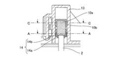
図7は、実施の形態2に係る車載用アクチュエータの構成を示す部分断面図である。
車載用アクチュエータ1aでは、検出用磁石10aとシャフト2との間に配置した固定部材16を介して、検出用磁石10aとシャフト2とが固定される。
固定部材16は、磁性体で構成され、ポジションセンサ用マグネット部10の検出用磁石10aに磁着する。また、固定部材16は、検出用磁石10aに磁着する面と対向する側に、シャフト2の先端部に設けた凸部2bを圧入させる圧入凹部16aが形成されている。また、固定部材16の外周側面には円環状の凹部16bが形成されている。Second Embodiment
The second embodiment shows a structure in which the
FIG. 7 is a partial cross-sectional view showing the configuration of the on-vehicle actuator according to the second embodiment.
In the in-
The fixing
ポジションセンサ用マグネット部10は、検出用磁石10aと外装部材10bとで一体構造となっている。ポジションセンサ用マグネット部10の一体構造は、例えば、検出用磁石10aを外装部材10bで鋳込み、成形することにより形成される。ポジションセンサ用マグネット部10のシャフト2が固定される面には、固定部材16が嵌合可能な嵌合凹部10cが外装部材10bにより形成される。嵌合凹部10cは、検出用磁石10aの磁石面が露出するように形成されている。また、嵌合凹部10cの内周面には、固定部材16の円環状の凹部16bと嵌合可能な円環状の凸部10dが形成されている。 The position
シャフト2の凸部2bは、固定部材16の圧入凹部16aに圧入されて固定され、その後、固定部材16がポジションセンサ用マグネット部10の嵌合凹部10cに挿入され、円環状の凹部16bと円環状の凸部10dとを嵌合させる。これにより、固定部材16の上面16cがポジションセンサ用マグネット部10の検出用磁石10aに着磁してシャフト2がポジションセンサ用マグネット部10に固定される。また、円環状の凹部16bと円環状の凸部10dとの嵌合により、シャフト2がポジションセンサ用マグネット部10から抜け落ちるのが抑制される。 The
また、固定部材16は、検出用磁石10aの磁力により、検出用磁石10aに磁着していることから、検出用磁石10aから離反することがない。また、仮に固定部材16が検出用磁石10aに磁着している力よりも大きな力が、固定部材16が検出用磁石10aから離反する方向に加わった場合にも、固定部材16の円環状の凹部16bと、外装部材10bの円環状の凸部10dとが嵌合していることから、固定部材16がポジションセンサ用マグネット部10から抜け落ちるのを抑制することができる。 Further, since the fixing
さらに、図8に示すように、固定部材16の検出用磁石10aと当接する上面16cは、適度な曲率半径を設けて構成される。これにより、固定部材16の上面16cと検出用磁石10aとは点接触となる。この点接触により、固定部材16がポジションセンサ用マグネット部10に対して若干の動きを許容するようにフレキシブルに固定され、シャフト2もポジションセンサ用マグネット部10に対してフレキシブルに固定される。さらに、固定部材16と嵌合凹部10cとの間にクリアランスが存在する。これによっても、固定部材16がポジションセンサ用マグネット部10に対してフレキシブルに固定され、シャフト2もポジションセンサ用マグネット部10に対してフレキシブルに固定される。 Furthermore, as shown in FIG. 8, the
固定部材16およびシャフト2が、ポジションセンサ用マグネット部10に対してフレキシブルに固定されると、シャフト2の傾き等を許容することができ、シャフト2のシャフト長が長くなった場合にも、シャフト2が直動方向Xに直線移動する動作を妨げることがない。 When the fixing
以上のように、この実施の形態2によれば、シャフト2は、一端部に、固定された磁性体の固定部材16を備え、ポジションセンサ用マグネット部10は、固定部材16が磁着する嵌合凹部10cを備えるように構成したので、出力シャフトと検出シャフトとを一体化することができ、シャフトのシャフト長を長くした場合にも、車載用アクチュエータ全体のサイズが大型化するのを抑制することができる。 As described above, according to the second embodiment, the
また、この実施の形態2によれば、固定部材16が外装部材10bに嵌合凹部10cに嵌合され、固定部材16の外周側面に形成された円環状の凹部16bと、嵌合凹部10cの内周面に形成された円環状の凸部10dとが嵌合するように構成したので、シャフトがポジションセンサ用マグネット部から抜け落ちるのを抑制することができる。 Further, according to the second embodiment, the fixing
なお、上述した実施の形態2では、固定部材16が嵌合する嵌合凹部10cが検出用磁石10aの磁石面が露出するように形成される構成を示したが、検出用磁石10aの磁石面を露出させず、この磁石面を肉薄の外装部材10bで覆うように一体成形してもよい。 In the second embodiment described above, the fitting
実施の形態3.
実施の形態3では、ポジションセンサ用マグネット部10とケース13が、シャフト2の軸受け機能およびシャフト2の回転を抑制する機能を備える構成を示す。
実施の形態1および実施の形態2で示した車載用アクチュエータ1,1aは、図1で示したように、モータ部4のロッド3側には、シャフト2を直動方向Xに移動自在に支持するガイド穴11を開設したボス12が固定されている。Third Embodiment
The third embodiment shows a configuration in which the position
The on-
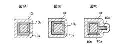
実施の形態1および実施の形態2のように、ガイド穴11を開設したボス12を備えている場合の、ポジションセンサ用マグネット部10とケース13の関係を図9Aに示している、図9Aは図2におけるC−C線断面図である。ポジションセンサ用マグネット部10とケース13との間には、クリアランスが設けられている。当該クリアランスにより、ポジションセンサ用マグネット部10に固定されたシャフト2が直動方向X以外の方向にも移動するが、ボス12に開設されたガイド穴11がシャフト2の移動をサポートし、且つシャフト2の回転を抑制することにより、回転子6の回転をシャフト2の直線運動に変換させることができ、シャフト2が直動方向Xに直線移動する動作を可能としている。 9A shows the relationship between the position
一方、この実施の形態3のポジションセンサ用マグネット部10とケース13の関係を図9Bおよび図9Cに示している。図9Bおよび図9Cは、図9Aと同様に、図2におけるC−C線断面図で想定される図を示している。
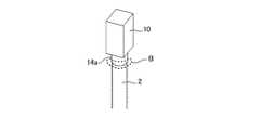
図9Bでは、ポジションセンサ用マグネット部10とケース13との間のクリアランスを、ポジションセンサ用マグネット部10がケース13内を移動可能な最小限のスペースに抑制している。また、図9Cでは、ポジションセンサ用マグネット部10とケース13との間のクリアランスは、図9Aと同様に設けているが、ポジションセンサ用マグネット部10の側面に外周方向に突出する角柱突部10eを設けている。この角柱突部10eが、ポジションセンサ用マグネット部10がケース13に対して回転する、またはがたつくのを抑制し、シャフト2が直動方向Xに直線移動するのをサポートする。On the other hand, FIGS. 9B and 9C show the relationship between the
In FIG. 9B, the clearance between the position
図9Bおよび図9Cに示したように、ポジションセンサ用マグネット部10の外周形状と、ケース13の内周形状とを、ポジションセンサ用マグネット部10とケース13と相互に回転するのを規制する形状とすることにより、図10に示す車載用アクチュエータ1bの構成を適用することができる。車載用アクチュエータ1bでは、シャフト2が軸周りに回転することなく直動方向Xに直線移動するのをサポートできるため、ガイド穴11を開設したボス12を設ける必要がなく、同様に車載用アクチュエータ1b全体のサイズを小さくすることができる。 As shown in FIG. 9B and FIG. 9C, a shape for restricting the rotation of the position
なお、実施の形態2で示した固定部材16を介して、シャフト2を検出用磁石10aに着磁させる場合には、固定部材16の外周を角柱形状にして、図9Bまたは図9Cに示したポジションセンサ用マグネット部10とケース13との関係を適用することにより、同様にシャフト2が軸周りに回転することなく直動方向Xに直線移動するのをサポートすることができ、車載用アクチュエータ1bの直動方向Xのサイズを小さくすることができる。 In the case where the
以上のように、この実施の形態3によれば、ポジションセンサ用マグネット部10の外周形形状と、ポジションセンサ用マグネット部10を収容するケース13の内周形状とが、回転子6の回転方向への互いの相対回転を規制する形状を有するように構成したので、シャフト2の直線移動をサポートし、回転を抑制するボス12を設ける必要がなくなり、車載用アクチュエータ全体のサイズを小さくすることができる。 As described above, according to the third embodiment, the outer peripheral shape of the position
上記以外にも、本発明はその発明の範囲内において、各実施の形態の自由な組み合わせ、あるいは各実施の形態の任意の構成要素の変形、もしくは各実施の形態において任意の構成要素の省略が可能である。 In addition to the above, within the scope of the present invention, the present invention can be implemented by free combination of each embodiment, or modification of any component of each embodiment, or omission of any component in each embodiment. It is possible.
この発明に係る車載用アクチュエータは、検出用シャフトと出力用シャフトを一体化することが可能なため、従来よりも長いシャフトの適用が要求される車載用アクチュエータを構成することができる。 Since the on-vehicle actuator according to the present invention can integrate the detection shaft and the output shaft, it can constitute an on-vehicle actuator requiring application of a shaft longer than the conventional one.
1,1a,1b 車載用アクチュエータ、2 シャフト、2a 雄ネジ部、2b 凸部、3 ロッド、4 モータ部、5 永久磁石、6 回転子、6a 中心穴、6b 雌ネジ部、7 整流子、8 ブラシ、9 電源供給端子部、10 ポジションセンサ用マグネット部、10a 検出用磁石、10b 外装部材、11 ガイド穴、12 ボス、13 ケース、14 金属部材、14a シャフト固定部、14b 検出用磁石固定部、15 ねじ、16 固定部材、17 部材、20 ポジションセンサ、30 レバー、31 支点、61 コア、62 ボビン、63 コイル。 1, 1a, 1b Automotive actuator, 2 shaft, 2a male screw, 2b convex, 3 rod, 4 motor, 5 permanent magnet, 6 rotor, 6a central hole, 6b female screw, 7 commutator, 8 Brush, 9 power supply terminal, 10 position sensor magnet, 10a detection magnet, 10b exterior member, 11 guide hole, 12 boss, 13 case, 14 metal member, 14a shaft fixing portion, 14b detection magnet fixing portion, 15 screws, 16 fixing members, 17 members, 20 position sensors, 30 levers, 31 supporting points, 61 cores, 62 bobbins, 63 coils.
Claims (3)
Translated fromJapanese前記固定子の内側に回転可能に配置された回転子と、
前記回転子の中央の穴部に形成された雌ネジ部と螺合する雄ネジ部を有し、前記回転子の回転を直線運動に変換して直線移動するシャフトと、
前記シャフトの軸方向の一端部に固定された、当該シャフトの直動位置を検出するためのポジションセンサ用マグネット部とを備え、
前記シャフトは、前記軸方向の一端部に、固定された磁性体の固定部材を備え、
前記ポジションセンサ用マグネット部は、前記固定部材が磁着する開口部を備えたことを特徴とする車載用アクチュエータ。With the stator,
A rotor rotatably disposed inside the stator;
A shaft having an external thread screwed with an internal thread formed in a central hole of the rotor and converting rotation of the rotor into linear motion for linear movement;
And a magnet portion for position sensor for detecting a linear movement position of the shaft, which is fixed to one end of the shaft in the axial direction,
The shaft includes a fixing member of a magnetic body fixed at one end in the axial direction,
The position magnet unit for sensordrive mounting actuators characterized in that the fixing member has an opening for magnetically attached.
前記固定子の内側に回転可能に配置された回転子と、
前記回転子の中央の穴部に形成された雌ネジ部と螺合する雄ネジ部を有し、前記回転子の回転を直線運動に変換して直線移動するシャフトと、
前記シャフトの軸方向の一端部に固定された、当該シャフトの直動位置を検出するためのポジションセンサ用マグネット部とを備え、
前記ポジションセンサ用マグネット部の外周形状と、前記ポジションセンサ用マグネット部を収容するケースの内周形状とは、前記回転子の回転方向への互いの相対回転を規制する形状であることを特徴とする車載用アクチュエータ。With the stator,
A rotor rotatably disposed inside the stator;
A shaft having an external thread screwed with an internal thread formed in a central hole of the rotor and converting rotation of the rotor into linear motion for linear movement;
And a magnet portion for position sensor for detecting a linear movement position of the shaft, which is fixed to one end of the shaft in the axial direction,
An outer peripheral shape of the position sensor magnet portion and an inner peripheral shape of a case accommodating the position sensor magnet portion are shapes which restrict relative rotation of the rotor in the rotation direction. actuator for placingthe car you.
Applications Claiming Priority (1)
| Application Number | Priority Date | Filing Date | Title |
|---|---|---|---|
| PCT/JP2016/069512WO2018003085A1 (en) | 2016-06-30 | 2016-06-30 | Vehicle-mounted actuator |
Publications (2)
| Publication Number | Publication Date |
|---|---|
| JPWO2018003085A1 JPWO2018003085A1 (en) | 2018-11-08 |
| JP6529673B2true JP6529673B2 (en) | 2019-06-12 |
Family
ID=60786275
Family Applications (1)
| Application Number | Title | Priority Date | Filing Date |
|---|---|---|---|
| JP2018524681AActiveJP6529673B2 (en) | 2016-06-30 | 2016-06-30 | Automotive actuator |
Country Status (2)
| Country | Link |
|---|---|
| JP (1) | JP6529673B2 (en) |
| WO (1) | WO2018003085A1 (en) |
Families Citing this family (2)
| Publication number | Priority date | Publication date | Assignee | Title |
|---|---|---|---|---|
| KR102213825B1 (en) | 2019-09-20 | 2021-02-08 | 주식회사 현대케피코 | Electronic shift lever |
| CN117713398B (en)* | 2024-02-05 | 2024-05-07 | 西南交通大学 | A high-precision direct-drive electromechanical actuator |
Family Cites Families (6)
| Publication number | Priority date | Publication date | Assignee | Title |
|---|---|---|---|---|
| GB9323340D0 (en)* | 1993-11-11 | 1994-01-05 | Allied Signal Ltd | Turbochargers for internal combustion engines |
| JP3792540B2 (en)* | 2001-05-30 | 2006-07-05 | 株式会社大林組 | Junction structure |
| JP2002372116A (en)* | 2001-06-12 | 2002-12-26 | Asahi Seiko Co Ltd | Electric cylinder |
| JP3971182B2 (en)* | 2001-12-28 | 2007-09-05 | 矢崎総業株式会社 | Parts mounting structure |
| JP2009293716A (en)* | 2008-06-06 | 2009-12-17 | Jtekt Corp | Electromagnetic damper |
| JP6349627B2 (en)* | 2013-05-29 | 2018-07-04 | アイシン精機株式会社 | Displacement detection device for linear motion mechanism, and rear wheel steering device for vehicle equipped with the device |
- 2016
- 2016-06-30JPJP2018524681Apatent/JP6529673B2/enactiveActive
- 2016-06-30WOPCT/JP2016/069512patent/WO2018003085A1/ennot_activeCeased
Also Published As
| Publication number | Publication date |
|---|---|
| JPWO2018003085A1 (en) | 2018-11-08 |
| WO2018003085A1 (en) | 2018-01-04 |
Similar Documents
| Publication | Publication Date | Title |
|---|---|---|
| JP4457038B2 (en) | Motor driven throttle control device for internal combustion engine | |
| JP2003348785A (en) | Motor | |
| CN112443696B (en) | Throttle valve device and magnetizing method thereof | |
| US7816819B2 (en) | Motor with cover member intergrally formed with a stator and holding a connector pin | |
| JP2008240610A (en) | Throttle device of internal combustion engine | |
| US11092086B2 (en) | Throttle valve device | |
| US11799349B2 (en) | Motor | |
| JPWO2009084131A1 (en) | Valve device | |
| JP2019122079A (en) | Electric actuator | |
| JP4259315B2 (en) | Electronically controlled throttle control device | |
| US20220263395A1 (en) | Electric Actuating Unit | |
| JP6529673B2 (en) | Automotive actuator | |
| JP2019122082A (en) | Electric actuator | |
| US9246368B2 (en) | Claw pole type motor | |
| JP2006005987A (en) | Motor bearing holding structure | |
| CN112443695B (en) | Throttle valve device | |
| JPWO2018147052A1 (en) | Rotor for motor, motor and method for manufacturing motor rotor | |
| JP4589786B2 (en) | Motor rotor and motor | |
| CN211429070U (en) | Motor and valve element driving device | |
| JP4831085B2 (en) | Electronic throttle device for internal combustion engines | |
| WO2020129849A1 (en) | Throttle device and method for manufacturing throttle device | |
| JP2004343992A (en) | Electric motor for linear drive | |
| JP7153461B2 (en) | motor | |
| JP5046094B2 (en) | Linear actuator | |
| JP7019810B2 (en) | Actuator |
Legal Events
| Date | Code | Title | Description |
|---|---|---|---|
| A521 | Request for written amendment filed | Free format text:JAPANESE INTERMEDIATE CODE: A523 Effective date:20180625 | |
| A621 | Written request for application examination | Free format text:JAPANESE INTERMEDIATE CODE: A621 Effective date:20180625 | |
| TRDD | Decision of grant or rejection written | ||
| A01 | Written decision to grant a patent or to grant a registration (utility model) | Free format text:JAPANESE INTERMEDIATE CODE: A01 Effective date:20190416 | |
| A61 | First payment of annual fees (during grant procedure) | Free format text:JAPANESE INTERMEDIATE CODE: A61 Effective date:20190514 | |
| R150 | Certificate of patent or registration of utility model | Ref document number:6529673 Country of ref document:JP Free format text:JAPANESE INTERMEDIATE CODE: R150 | |
| R250 | Receipt of annual fees | Free format text:JAPANESE INTERMEDIATE CODE: R250 | |
| R250 | Receipt of annual fees | Free format text:JAPANESE INTERMEDIATE CODE: R250 | |
| R250 | Receipt of annual fees | Free format text:JAPANESE INTERMEDIATE CODE: R250 | |
| S111 | Request for change of ownership or part of ownership | Free format text:JAPANESE INTERMEDIATE CODE: R313111 | |
| R350 | Written notification of registration of transfer | Free format text:JAPANESE INTERMEDIATE CODE: R350 | |
| R250 | Receipt of annual fees | Free format text:JAPANESE INTERMEDIATE CODE: R250 |