JP6528239B2 - Communication device and program - Google Patents
Communication device and programDownload PDFInfo
- Publication number
- JP6528239B2 JP6528239B2JP2015138416AJP2015138416AJP6528239B2JP 6528239 B2JP6528239 B2JP 6528239B2JP 2015138416 AJP2015138416 AJP 2015138416AJP 2015138416 AJP2015138416 AJP 2015138416AJP 6528239 B2JP6528239 B2JP 6528239B2
- Authority
- JP
- Japan
- Prior art keywords
- message
- unit
- determination
- state
- filter unit
- Prior art date
- Legal status (The legal status is an assumption and is not a legal conclusion. Google has not performed a legal analysis and makes no representation as to the accuracy of the status listed.)
- Active
Links
Images


Landscapes
- Small-Scale Networks (AREA)
- Mobile Radio Communication Systems (AREA)
Description
Translated fromJapanese本発明は、バスで接続された通信システムにおける通信装置およびプログラムに関する。The present invention relates to acommunication apparatus and program in a communication system connected by a bus.
車載ネットワークにおいて、不正なデータを侵入させて誤動作させる攻撃を検知し防御することが求められる。そのため、フィルタテーブルに監視すべきIDを記憶しておき、記憶したIDのメッセージの送信周期をチェックすることによって、不正なデータの侵入が検出される。つまり、正規の送信ノードが、所定のIDのメッセージを周期的に送信している場合、不正な送信ノードが、なりすまし攻撃により不正なデータを送信すると、周期異常により不正なデータが検出可能である(例えば、特許文献1参照)。 In an in-vehicle network, it is required to detect and prevent an attack that intrudes illegitimate data and causes a malfunction. Therefore, the ID to be monitored is stored in the filter table, and by checking the transmission cycle of the stored ID message, intrusion of unauthorized data is detected. That is, when a legitimate transmitting node periodically transmits a message of a predetermined ID, if an illegal transmitting node transmits invalid data by a spoofing attack, invalid data can be detected due to a cycle abnormality. (See, for example, Patent Document 1).
フィルタテーブルによるフィルタリング処理では、受信したメッセージに対して不正か否かを即時に判定したり、あるいは一定時間待機後に判定したりする。一方、不正なメッセージを判定するために待機可能な時間は、メッセージに応じて異なる。不正なメッセージの検出精度を向上するためには、最適な待機時間を設定することが求められる。 In the filtering process by the filter table, it is immediately determined whether or not the received message is incorrect, or after waiting for a predetermined time. On the other hand, the time that can be waited to determine an incorrect message varies depending on the message. In order to improve the detection accuracy of an incorrect message, it is required to set an optimum waiting time.
本発明はこうした状況に鑑みなされたものであり、その目的は、不正なメッセージの検出精度を向上する技術を提供することにある。 The present invention has been made in view of such circumstances, and an object thereof is to provide a technique for improving the accuracy of detecting an unauthorized message.
上記課題を解決するために、本発明のある態様の通信装置は、ネットワークにおけるメッセージを受信する通信部と、通信部において受信されるメッセージのうち、ネットワークが設けられた物体の第1状態および第1状態とは異なる物体の第2状態のいずれか一方で設定されたIDに対応する第1メッセージに対して、メッセージの種類に応じて遅延時間を設定する設定部と、第1メッセージが不正なメッセージであるか否かの判定を、第1状態および第2状態のいずれでも設定されたIDに対応する第2メッセージに対して行うタイミングから設定部において設定された遅延時間まで遅らせながら、第1メッセージに対するフィルタリング処理を実行するフィルタ部と、を備える。In order to solve the above problems, a communication apparatus according to an aspect of the present invention includes a communication unit for receiving a message in anetwork, and a first state ofan object provided with a network and a first state of messages received in the communication unit. For the first message corresponding to the ID set in oneof the second states of theobject different from the one state, the setting unit for setting the delay time according to the type of the message, and the first message being invalid While delaying from the timing performed on the second message corresponding to the ID set in either the first state or the second state to the delay time set in the setting unit, the first And a filter unit that executes a filtering process on the message.
本発明の別の態様もまた、通信装置である。この装置は、ネットワークにおけるメッセージを受信する通信部と、通信部において受信されるメッセージの種類に応じて遅延時間を設定する設定部と、受信されたメッセージのうちの第1メッセージが不正なメッセージであるか否かの判定を、ネットワークが設けられた物体の第1状態および物体の第2状態のいずれでも設定されたIDに対応する第2メッセージに対して行うタイミングから設定部において設定された遅延時間まで遅らせながら、第1メッセージに対するフィルタリング処理を実行するフィルタ部とを備える。フィルタ部は、設定部において設定された遅延時間まで判定を遅らせずに、第1メッセージに対するフィルタリング処理を実行して、判定結果を出力する第1フィルタ部と、設定部において設定した遅延時間まで判定を遅らせながら、第1メッセージに対するフィルタリング処理を実行する第2フィルタ部と、第2フィルタ部での判定結果が、第1フィルタ部での判定結果と異なっている場合、第1フィルタ部での判定結果を修正するための情報を出力する修正部と、を備える。Another aspect of the present invention is also a communication device. This apparatus comprises a communication unit for receiving a message in the network, a setting unit for setting a delay time according to the type of message received by the communication unit, and a first message among the received messages being an invalid message. The delay set in the setting unit from the timing at which the determination as to whether or not there is a second message corresponding to the ID set in either the first stateof theobject provided with thenetwork or the second state of theobject And a filter unit that performs a filtering process on the first message while delaying time. The filter unit executes the filtering process on the first message without delaying the determination until the delay time set by the setting unit, and determines the first filter unit outputting the determination result and the delay time set by the setting unit When the determination result in the second filter unit that executes the filtering process on the first message while delaying the second message and the determination result in the second filter unit is different from the determination result in the first filter unit, the determination in the first filter unit And a correction unit that outputs information for correcting the result.
なお、以上の構成要素の任意の組合せ、本発明の表現を方法、装置、システム、コンピュータプログラム、またはコンピュータプログラムを記録した記録媒体などの間で変換したものもまた、本発明の態様として有効である。 It is to be noted that any combination of the above-described components, and a conversion of the expression of the present invention between a method, an apparatus, a system, a computer program, or a recording medium having a computer program recorded thereon is also effective as an aspect of the present invention. is there.
本発明によれば、不正なメッセージの検出精度を向上できる。 According to the present invention, it is possible to improve the detection accuracy of an unauthorized message.
(実施例1)
本発明の実施例1を具体的に説明する前に、実施例1の概要を説明する。実施例1は、車載ネットワークであるCAN(Controller Area Network)における不正なメッセージを検出する通信装置に関する。CANはバス型ネットワークを採用したシリアル通信プロトコルである。バスに接続される各通信装置からのメッセージは、バスに接続されるすべての通信装置にブロードキャスト送信される。当該メッセージには送信元通信装置および宛先通信装置の識別情報が含まれない。したがって、メッセージを受信した通信装置は、正規の通信装置からのメッセージであるか否かを単純に判定できない。そのため、不正なメッセージの検出精度を向上することが望まれる。Example 1
Before concretely explaining Example 1 of the present invention, an outline of Example 1 will be described. The first embodiment relates to a communication device that detects an unauthorized message in a controller area network (CAN) that is an in-vehicle network. CAN is a serial communication protocol that employs a bus network. A message from each communication device connected to the bus is broadcasted to all communication devices connected to the bus. The message does not include identification information of the source communication device and the destination communication device. Therefore, the communication device that has received the message can not simply determine whether the message is from the legitimate communication device. Therefore, it is desirable to improve the detection accuracy of an unauthorized message.
本実施例に係る通信装置は、CANの通信仕様にもとづいた通信規則であって、かつ正しいメッセージの通信規則をルールとして保持する。ここで、通信規則の一例は、対象のCANで送信可能なCANのメッセージID(以下、「CAN ID」)である。また、通信規則の一例は、CAN IDごとのDLC(データ長)、送信周期、送信頻度、データの取り得る値、データの増加・減少の規則などであってもよい。通信装置は、通信仕様に応じたフィルタリングルールを設定しており、フィルタリングルールによって、送受信されるCANのメッセージをフィルタリング処理する。また、通信装置は、フィルタリング処理の判定結果をもとに、アプリケーションあるいはCANバスに、メッセージを出力するか否かを決定する。 The communication apparatus according to the present embodiment is a communication rule based on the CAN communication specification, and holds a correct message communication rule as a rule. Here, an example of the communication rule is a CAN message ID (hereinafter, "CAN ID") that can be transmitted by the target CAN. Further, an example of the communication rule may be DLC (data length) for each CAN ID, transmission cycle, transmission frequency, possible value of data, rule of increase / decrease of data, or the like. The communication apparatus sets a filtering rule according to the communication specification, and performs filtering processing of CAN messages transmitted and received by the filtering rule. Also, the communication apparatus determines whether to output a message to the application or the CAN bus based on the determination result of the filtering process.
メッセージの内容によってはフィルタリング処理の結果を即時に判定できない場合がある。このような場合があっても、フィルタリング処理によって不正なメッセージの検出精度を向上することが望まれる。これに対応するために、本実施例に係る通信装置は、メッセージの種類に応じて遅延時間を設定し、設定した遅延時間までフィルタリング処理の判定を延期させる。 Depending on the content of the message, the result of the filtering process may not be determined immediately. Even in such a case, it is desirable to improve the detection accuracy of an incorrect message by filtering processing. In order to cope with this, the communication apparatus according to the present embodiment sets the delay time according to the type of the message, and postpones the determination of the filtering process until the set delay time.
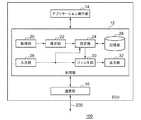
図1は、本発明の実施例1に係るCANシステム500の構成を示す。CANシステム500は、ECU(Electronic Control Unit)100と総称される第1ECU100a、第2ECU100b、第3ECU100c、第4ECU100d、CANバス200を含む。なお、CANシステム500に含まれるECU100の数は、「4」に限定されない。 FIG. 1 shows the configuration of a
各ECU100は、車両に搭載されたエンジン、モータ、メータ、トランスミッション、ブレーキ、エアバッグ、ランプ、パワーステアリング、パワーウィンドウ、カーエアコン等を制御するユニットであり、例えば、マイクロコントローラを搭載する。各ECU100は、CANバス200に接続されており、CANの通信を実行する。そのため、各ECU100は、前述の「通信装置」に相当する。CANバス200は、例えば、2本の通信線によって構成されており、電圧の差動によって信号を伝送する。 Each ECU 100 is a unit for controlling an engine, a motor, a meter, a transmission, a brake, an air bag, a lamp, a power steering, a power window, a car air conditioner and the like mounted on a vehicle. Each
CANではCSMA/CA(Carrier Sense Multiple Access with Collision Avoidance)と呼ばれるアクセス制御方式が採用されている。CSMA/CAでは、CANバス200に対して最初に送信を開始したECU100が送信権を取得する。なお、同時に複数のECU100が送信した場合は、通信調停(bus arbitration)が行われる。CANでは、CAN IDの値が小さい方が優先される。 In CAN, an access control method called Carrier Sense Multiple Access with Collision Avoidance (CSMA / CA) is adopted. In CSMA / CA, the
図2は、CANシステム500で使用される標準フォーマットのデータフレームを示す。図示のごとく、SOF、IDフィールド、RTR、IDE、r0、DLC、データフィールド、CRCデリミタ、Ack、Ackデリミタ、EOFが先頭から順に配置されることによって、データフレームが構成される。各ボックス内の数字はビット数を示す。またボックスの上が開放されている項目は常に「0」をとる項目であり、ボックスの下が開放されている項目は常に「1」をとる項目である。上下が開放されていない項目は「0」と「1」の両方をとりうる項目である。なお、送信可能な状態のデータフレームは、メッセージと呼ばれる。 FIG. 2 shows a data frame in a standard format used in
IDフィールドには、前述のCAN IDが格納される。CAN IDは、メッセージの種類および優先度を表すための識別情報である。CANにおけるメッセージには、車両内の特定の処理対象における特定の通知事項が含まれる。当該処理対象には、特定の監視対象および特定の制御対象が含まれる。例えば、車両内の特定の処理対象に関するメッセージとして、速度情報を含むメッセージ、ドアの開閉を指示するメッセージ等がある。また、同じ処理対象に対して複数の通知事項が設定されることがある。例えば、1つのメータに対してエンジン回転数を通知するための通知事項、エンジン水温を通知するための通知事項などの複数の通知事項が設定可能である。 The above-mentioned CAN ID is stored in the ID field. The CAN ID is identification information for indicating the type and priority of the message. The message in CAN includes specific notification items in a specific processing target in the vehicle. The processing targets include specific monitoring targets and specific control targets. For example, as a message regarding a specific processing target in a vehicle, there is a message including speed information, a message instructing to open and close a door, and the like. Also, multiple notification items may be set for the same processing target. For example, a plurality of notification items such as a notification item for notifying an engine rotation speed to one meter and a notification item for notifying an engine water temperature can be set.
CAN IDは、送信されるメッセージに含まれる特定の処理対象の特定の通知事項に関連づけられている。メッセージを受信したECU100では、そのCAN IDにもとづいて、メッセージに含まれる特定の通知事項の内容を判断する。図2に示すように、CANのデータフレームには送信先アドレスおよび送信元アドレスが含まれない。そのため、受信側のECU100は、正しい通信相手からのメッセージであるか否かを判断できない。例えば、エンジン回転数を含むメッセージは、エンジンのECU100から送信される。当該メッセージに付与されるCAN IDと同じCAN IDが付与されたメッセージが、不正なECU100から送信されると、受信側のECU100は、正当なエンジンのECU100からのメッセージであるか、不正なECU100からのメッセージであるかを判別できない。 The CAN ID is associated with a particular notification subject to be processed that is included in the message to be sent. The
不正なECU100が送信側のECU100になりすまして不正な情報を含むメッセージを送信し、かつ受信側のECUが、これを正当なメッセージとして処理した場合、その後の処理(補機の制御など)に悪影響が及んでしまう。例えば、不正なECU100が、エンジンのECU100になりすましてエンジン回転数を含むメッセージを送信することにより、それを受信したメータのECU100の制御に悪影響が及ぶ。このようにCANプロトコルでは、なりすましがなされやすい。また、メッセージがCANバス200に対してブロードキャスト送信されるので、ユニキャスト送信よりも盗聴がなされやすい。 If the
図3は、ECU100の構成を示す。ECU100は、通信部10、処理部12、アプリケーション実行部14を含む。処理部12は、取得部20、推定部22、設定部24、記憶部26、入力部28、フィルタ部30、出力部32を含む。 FIG. 3 shows the configuration of the
アプリケーション実行部14は、各ECU100の処理対象(例えば、エンジン、ステアリング、ブレーキ、その他の各種補機)と接続し、それらの処理対象からステータス情報または指示情報を取得する。アプリケーション実行部14は、当該処理対象から取得した情報をもとに、CANにおいてブロードキャスト送信すべきデータを生成し、処理部12に出力する。また、アプリケーション実行部14は、CANバス200から受信されたメッセージに含まれるデータを処理部12から入力し、当該データに応じて当該処理対象を制御する。 The
通信部10は、ネットワークであるCANシステム500におけるメッセージを送受信する。具体的に説明すると、通信部10は、処理部12により生成されたメッセージであって、かつアプリケーション実行部14において生成されたデータが含まれたメッセージをCANバス200へブロードキャスト送信する。通信部10は、他のECU100で生成されCANバス200へブロードキャスト送信されたメッセージをCANバス200から受信する。通信部10は、受信したメッセージを処理部12に渡す。 The
処理部12は、アプリケーション実行部14と通信部10の間に配置される。処理部12は、アプリケーション実行部14からのデータを入力し、当該データが含まれたメッセージを生成する。処理部12は、生成したメッセージに対して、後述のフィルタリング処理を実行してから通信部10に出力する。一方、処理部12は、通信部10からのメッセージを入力し、入力したメッセージに対して、後述のフィルタリング処理を実行する。フィルタリング処理したメッセージに含まれたデータを抽出してアプリケーション実行部14に出力する。処理部12は、フィルタリング処理において、不正ではないメッセージだけを選択する。以下では、フィルタリング処理を中心に説明する。 The
取得部20は、CANシステム500が設けられた物体、例えば車両の状態に関する状態情報を取得する。車両の状態とは、イグニッションがオンになっているか、ACC(アクセサリーポジション)がオンになっているか、車速等であり、これらが状態情報に含まれている。取得部20は、例えば、状態情報を図示しないセンサ等から取得する。また、取得部20は、CANバス200から状態情報を取得してもよい。取得部20は、取得した状態情報を推定部22に出力する。 The
推定部22は、取得部20からの状態情報を入力する。推定部22は、状態情報をもとに、車両の状態を推定する。例えば、推定部22は、「第1状態」として、例えば、ACCがオンであることが示された状態情報をもとに、ACCがオンである状態を推定する。これに続いて、推定部22は、「第2状態」として、例えば、イグニッションがオンであることが示された状態情報をもとに、イグニッションがオンである情報を推定する。なお、推定部22において推定される状態、状態の遷移は、これらに限定されない。推定部22は、推定した車両の状態を設定部24に出力する。 The
所定のタイミングにおける車両の状態は、いずれかに特定されるべきである。第1状態から第2状態への遷移がなされる場合であっても、車両の状態は、第1状態あるいは第2状態で特定される。しかしながら、図1における各ECU100において推定される車両の状態にずれが生じる可能性がある。例えば、第1ECU100aは、車両の状態が第2状態であると推定し、第2ECU100bは、車両の状態が第1状態であると推定する。この場合、第1ECU100aにおいて、車両の状態が第1状態であると推定するタイミングが、第2ECU100bにおいて、車両の状態が第2状態であると推定するタイミングよりも遅れている。 The state of the vehicle at a predetermined timing should be specified in any way. Even when the transition from the first state to the second state is made, the state of the vehicle is specified as the first state or the second state. However, a deviation may occur in the state of the vehicle estimated in each
記憶部26は、正しいメッセージの通信規則をルールとして記憶する。前述のごとく、記憶されるルールは、送受信可能なCAN ID、CAN IDごとのDLC、CAN IDごとの送信周期、CAN IDごとの送信頻度、CAN IDごとのデータなどである記憶部26は、ルールに含まれる情報の一覧を記憶する。 The
設定部24は、推定部22から、車両の状態を入力する。設定部24は、推定部22において推定した車両の状態をもとに、フィルタリングルールを設定する。具体的に説明すると、設定部24は、記憶部26に記憶した情報の一覧から、推定部22において推定した車両の状態に適した一部の情報をフィルタリングルールとして選択する。なお、設定部24には、車両の状態と、選択すべき一部の情報との対応関係が予め記憶されている。記憶部26に記憶されている情報の一覧には、CAN IDだけではなく、DLC、送信周期等も含まれているが、ここでは、説明を明瞭にするために、CAN IDだけを説明の対象とする。 The setting
例えば、推定部22が第1状態を推定した場合に、記憶部26は、第1状態に対応したフィルタリングルールを設定する。図4(a)−(b)は、設定部24において設定されるフィルタリングルールのデータ構造を示す。図4(a)は、第1状態、つまりACCがオンである状態において設定されるフィルタリングルールを示す。図示のごとく、CAN IDの「0x100」、「0x200」、「0x300」、「0x110」、「0x210」、「0x310」が設定されている。図3に戻る。 For example, when the
例えば、推定部22が第2状態を推定した場合に、記憶部26は、第2状態に対応したフィルタリングルールを設定する。図4(b)は、第2状態、つまりイグニッションがオンである情報において設定されるフィルタリングルールを示す。図示のごとく、CAN IDの「0x120」、「0x220」、「0x320」、「0x400」、「0x110」、「0x210」、「0x310」が設定されている。なお、CAN IDの「0x110」、「0x210」、「0x310」は、第1状態においても含まれるので、複数の状態で共通に設定されうるCAN IDである。また、CAN IDの「0x120」、「0x220」、「0x320」、「0x400」は、第1状態において含まれないので、第2状態のみで設定されうるCAN IDである。図3に戻る。 For example, when the
入力部28は、ECU100が送信側に相当する場合、アプリケーション実行部14からのデータが含まれたメッセージを入力する。一方、入力部28は、ECU100が受信側に相当する場合、通信部10からのメッセージを入力する。入力部28は、メッセージを設定部24、フィルタ部30に出力する。 When the
設定部24は、入力部28からのメッセージを入力する。設定部24は、入力したメッセージ、つまり通信部10において送受信されるメッセージの種類に応じて、フィルタ部30において判定を延期する際の遅延時間を設定する。これは、前述のごとく、車両が第1状態から第2状態へ遷移する場合、ECU100ごとに推定される状態が異なる場合があり、それに対応するためになされる。例えば、車両が第2状態であると推定している第1ECU100aによって、メッセージが送信され、当該車両が第1状態であると推定している第2ECU100bによって、当該メッセージが受信される場合である。この場合、第1ECU100aは、例えば、CAN ID「0x120」のメッセージを正規のメッセージとして送信するが、第2ECU100bは、そのようなCAN IDをフィルタリングルールに含めていない。その結果、第2ECU100bは、当該メッセージを受信せず、不正なメッセージと判定する。このような状況は、車両の状態の推定にずれが生じる可能性のある場合、例えば、ACCのオン/オフやイグニッションのオン/オフの場合に発生する。 The setting
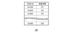
このようなずれに対応するために、設定部24は、推定のずれが発生しうる場合に、フィルタリング処理における判定を延期させる。また、前述のごとく、判定を延期させるための遅延時間は、メッセージの種類ごとに決められる。例えば、メッセージの種類ごとに求められる即時応答性を判定し、即時応答性の高いメッセージに対してすぐに判定が実行され、即時応答性の低いメッセージに対して遅延時間だけ判定が保留されてもよい。設定部24は、遅延時間を設定するために、記憶部26に記憶されたテーブルを参照する。図5は、記憶部26に記憶されるテーブルのデータ構造を示す。図示のごとく、各CAN IDに対する遅延時間が示される。なお、遅延時間は、「0」であってもよく、それは判定を延期させないことに相当する。図3に戻る。 In order to cope with such a deviation, the setting
遅延時間について、前述のごとく、第1状態から第2状態に遷移する場合を一例として説明する。図4(a)−(b)のごとく、CAN IDの「0x100」、「0x200」、「0300」、「0x120」、「0x220」、「0x320」、「0x400」については、第1状態と第2状態のいずれか一方のみで設定される。そのため、これらのCAN IDに対しては、複数のECU100間の推定のずれに応じた時間が遅延時間として設定される。一方、CAN IDの「0x110」、「0x210」、「0x310」については、第1状態と第2状態のいずれでも設定される。そのため、これらのCAN IDに対しては、遅延時間が「0」に設定される。設定部24は、設定した遅延時間をフィルタ部30に設定する。なお、設定部24は、メッセージごとに異なった遅延時間を設定してもよい。 Regarding the delay time, as described above, the case of transition from the first state to the second state will be described as an example. As shown in Fig. 4 (a)-(b), for the CAN IDs "0x100", "0x200", "0300", "0x120", "0x220", "0x320" and "0x400", the first state and the first state It is set in only one of the two states. Therefore, for these CAN IDs, a time corresponding to the deviation of estimation among the plurality of
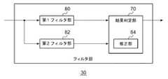
フィルタ部30は、入力部28からのメッセージを入力する。また、フィルタ部30は、設定部24によって、フィルタリングルールを設定されるとともに、遅延時間も設定される。フィルタ部30は、フィルタリングルールと遅延時間にしたがって、メッセージに対するフィルタリング処理を実行する。図6は、フィルタ部30の構成を示す。フィルタ部30は、第1ルール記憶部50、第2ルール記憶部52、第3ルール記憶部54、第4ルール記憶部56、第5ルール記憶部58、IDフィルタ部60、DLCフィルタ部62、送信周期フィルタ部64、送信頻度フィルタ部66、データフィルタ部68、結果判定部70を含む。 The
第1ルール記憶部50は、設定部24において設定されたフィルタリングルールのうち、CAN IDに関するルールを記憶する。第1ルール記憶部50は、例えば、図4(a)−(b)のようなCAN IDを記憶する。なお、車両の状態に応じて、設定部24は、フィルタリングルールを変更するので、第1ルール記憶部50に記憶されるルールも変更される。IDフィルタ部60は、入力部28からのメッセージに対して、設定部24において設定した遅延時間まで判定を遅らせながら、CAN IDによるフィルタング処理を実行する。つまり、IDフィルタ部60は、第1ルール記憶部50に記憶されたCAN IDが含まれたメッセージを抽出する。なお、IDフィルタ部60は、遅延時間に達していなくても、可能であればメッセージを抽出してもよい。 The first
第2ルール記憶部52は、設定部24において設定されたフィルタリングルールのうち、DLCに関するルールを記憶する。第3ルール記憶部54は、設定部24において設定されたフィルタリングルールのうち、送信周期に関するルールを記憶する。第4ルール記憶部56は、設定部24において設定されたフィルタリングルールのうち、送信頻度に関するルールを記憶する。これは、例えば、異常に高い頻度で送信される場合を除外するように定められる。第5ルール記憶部58は、設定部24において設定されたフィルタリングルールのうち、データに関するルールを記憶する。これは、例えば、固定値である部分が異常な値になってる場合を除外したり、増加/減少の傾向が異常なもの場合を除外したりするように定められる。なお、第2ルール記憶部52から第5ルール記憶部58は、第1ルール記憶部50と同様に、設定部24によって設定される。 The second
DLCフィルタ部62は、入力部28からのメッセージに対して、第2ルール記憶部52に記憶されたDLCによるフィルタング処理を実行する。送信周期フィルタ部64は、入力部28からのメッセージに対して、第3ルール記憶部54に記憶された送信周期によるフィルタング処理を実行する。送信頻度フィルタ部66は、入力部28からのメッセージに対して、第4ルール記憶部56に記憶された送信周期によるフィルタング処理を実行する。送信周期フィルタ部64は、入力部28からのメッセージに対して、第5ルール記憶部58に記憶されたデータによるフィルタング処理を実行する。DLCフィルタ部62からデータフィルタ部68は、IDフィルタ部60と同様の処理を実行する。なお、DLCフィルタ部62からデータフィルタ部68には、IDフィルタ部60と同様に、設定部24によって遅延時間が設定される。 The
結果判定部70は、IDフィルタ部60からデータフィルタ部68でのフィルタリング処理の結果を入力する。結果判定部70は、フィルタリング処理の結果をもとに、判定を実行する。例えば、IDフィルタ部60からデータフィルタ部68のすべてにおいてメッセージが抽出されている場合、結果判定部70は、当該抽出されたメッセージが正規のメッセージであると判定する。一方、IDフィルタ部60からデータフィルタ部68のいずれかにおいてメッセージが抽出されていない場合、結果判定部70は、入力部28からのメッセージが、不正なメッセージであると判定する。結果判定部70は、正規のメッセージであると判定した場合、当該メッセージを出力する。一方、結果判定部70は、不正なメッセージであると判定した場合、何も出力しないか、不正なメッセージを検出した旨を出力する。 The
なお、結果判定部70は、IDフィルタ部60からデータフィルタ部68の1つ以上においてメッセージが抽出されている場合、当該抽出されたメッセージが正規のメッセージであると判定してもよい。その際、この条件を満たさなければ、結果判定部70は、入力部28からのメッセージが、不正なメッセージであると判定してもよい。図3に戻る。 When one or more of the data filter
出力部32は、結果判定部70からのメッセージを入力する。出力部32は、ECU100が送信側に相当する場合、メッセージを通信部10に出力する。一方、出力部32は、ECU100が受信側に相当する場合、メッセージに含まれたデータをアプリケーション実行部14に出力する。 The
この構成は、ハードウエア的には、任意のコンピュータのCPU、メモリ、その他のLSIで実現でき、ソフトウエア的にはメモリにロードされたプログラムなどによって実現されるが、ここではそれらの連携によって実現される機能ブロックを描いている。したがって、これらの機能ブロックがハードウエアのみ、ハードウエアとソフトウエアの組合せによっていろいろな形で実現できることは、当業者には理解されるところである。 In terms of hardware, this configuration can be realized with the CPU, memory, or other LSI of any computer, and with software, it can be realized by a program loaded into the memory, etc. Are drawing functional blocks. Therefore, it is understood by those skilled in the art that these functional blocks can be realized in various forms only by hardware and by a combination of hardware and software.
以上の構成によるCANシステム500の動作を説明する。図7は、CANシステム500による判定手順を示すシーケンス図である。第1ECU100aは、イグニッションがオンである状態を認識する(S50)。第1ECU100aは、イグニッションがオンである状態に対応したメッセージを送信する(S52)。第2ECU100bは、メッセージに対する判定を行わずに、イグニッションがオンである状態を認識する(S54)。その後、第2ECU100bは、当該メッセージが正規のメッセージであると判定する(S56)。 The operation of the
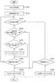
図8は、ECU100による判定手順を示すフローチャートである。設定部24は、CAN IDを取得し(S100)、それに応じた遅延時間を設定する(S102)。フィルタ部30は、判定結果が保留であり(S104のY)、遅延時間が経過しなければ(S106のN)、ステップ104に戻る。遅延時間が経過すれば(S106のY)、フィルタ部30は、不正なメッセージと判定する(S110)。フィルタ部30は、判定結果が保留でなく(S104のN)、判定結果がOKでなければ(S108のN)、不正なメッセージと判定する(S110)。フィルタ部30は、判定結果がOKであれば(S108のY)、正規のメッセージと判定する(S112)。なお、ステップ106における遅延時間が経過していない場合の処理として、ステップ106のNからステップ104へは、遅延時間が経過しない範囲内で、一定時間経過してから移行してもよい。また、フィルタリング処理に利用可能な情報が追加された時点で移行するよう制御してもよい。 FIG. 8 is a flowchart showing the determination procedure by the
本実施例によれば、メッセージの種類に応じて設定した遅延時間まで判定を遅らせるので、直ちに判定できない場合でも正確な判定を実行できる。また、直ちに判定できない場合でも正確な判定が実行されるので、不正なメッセージの検出精度を向上できる。また、直ちに判定できない場合でも判定を遅延させるので、推定した車両の状態がECUごとに異なる場合でも、不正なメッセージの検出精度を向上できる。 According to this embodiment, since the determination is delayed until the delay time set according to the type of the message, accurate determination can be performed even when the determination can not be made immediately. Further, even if the determination can not be made immediately, the accurate determination is performed, so that the accuracy of detecting an incorrect message can be improved. Further, even if the determination can not be made immediately, the determination is delayed, so that the accuracy of detecting an incorrect message can be improved even when the estimated vehicle state is different for each ECU.
また、状態情報をもとに推定した車両の状態に応じたフィルタリングルールを設定するので、そのときの車両の状態に応じたフィルタリングルールだけを使用できる。また、車両の状態に応じたフィルタリングルールだけが使用されるので、不正なメッセージの検出精度を向上できる。また、変動する車両の状態に応じてルールセットを動的に切りかえるので、検知率を向上させ、誤検知率を低下できる。 Moreover, since the filtering rule according to the state of the vehicle estimated based on state information is set, only the filtering rule according to the state of the vehicle at that time can be used. Moreover, since only the filtering rule according to the state of the vehicle is used, the detection accuracy of an incorrect message can be improved. In addition, since the rule set is dynamically switched according to the changing state of the vehicle, the detection rate can be improved and the false detection rate can be reduced.
(実施例2)
次に、実施例2を説明する。実施例2は、実施例1と同様に、CANにおける不正なメッセージを検出する通信装置、つまりECUに関する。実施例2でも、メッセージの種類に応じた遅延時間まで判定を遅らせながら、フィルタング処理を実行する。実施例2は、遅延時間まで判定を遅らせている場合のフィルタリング処理に関しており、延期させている間に、後から追加された情報を考慮したり、複数メッセージ間の相関を考慮したりして、判定を実行する。実施例2に係るCANシステム500は、図1と同様のタイプである。また、実施例2に係るECU100は、図3と同様のタイプであってもよいが、車両の状態に応じたフィルリングルールを設定せずに、固定のフィルタリングルールが使用されてもよい。その際は、図3の取得部20、推定部22が省略されてもよい。ここでは、固定のフィルタリングルールが使用されているとし、これまでとの差異を中心に説明する。(Example 2)
Next, Example 2 will be described. The second embodiment relates to a communication device, that is, an ECU that detects an incorrect message in CAN, as in the first embodiment. Also in the second embodiment, the filtering process is performed while delaying the determination until the delay time corresponding to the type of the message. The second embodiment relates to the filtering process when the determination is delayed until the delay time, and during the delaying, considering the information added later or considering the correlation between multiple messages, Execute the judgment. The
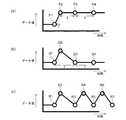
図9(a)−(c)は、本発明の実施例2に係るフィルタ部30の動作概要を示す。これらは、特に、同一のCAN IDに対して、図6のデータフィルタ部68に入力されるデータ値の時間変化を示しており、縦軸がデータ値を示し、横軸が時間を示す。また、このようなデータ値が含まれたメッセージは周期的に発生しているとし、その送信周期が「T」と示される。 FIGS. 9A to 9C show an operation outline of the
図9(a)は、周期的なメッセージに加えて、何らかのトリガによってイベント的にメッセージが発生している場合の一例を示す。ポイント「P1」は、周期的なメッセージ含まれたデータを示す。ポイント「P2」は、イベント的なメッセージに含まれたデータを示し、ポイント「P1」から間隔「T’」で発生している。ポイント「P2」は、設定変更などで発生するので、ポイント「P1」でのデータ値とは異なったデータ値を有する。 FIG. 9A shows an example of a case where a message is generated as an event by some trigger in addition to the periodic message. Point “P1” indicates periodic message included data. Point “P2” indicates data included in an eventual message, and occurs at an interval “T ′” from point “P1”. The point "P2" is generated due to a setting change or the like, and thus has a data value different from the data value at the point "P1".
ポイント「P3」は、ポイント「P2」から送信周期「T」で発生した周期的なメッセージである。そのため、ポイント「P3」のデータ値は、ポイント「P2」のデータ値と同一である。また、ポイント「P4」は、ポイント「P3」から送信周期「T」で発生した周期的なメッセージである。そのため、ポイント「P4」のデータ値も、ポイント「P2」のデータ値と同一である。 Point "P3" is a periodic message generated from transmission point "T" from point "P2". Therefore, the data value of the point "P3" is the same as the data value of the point "P2". Also, the point "P4" is a periodic message generated from the point "P3" in the transmission cycle "T". Therefore, the data value of the point “P4” is also the same as the data value of the point “P2”.
このような傾向を示す図9(a)のポイント「P1」からポイント「P4」のメッセージは、正規のメッセージであるので、データフィルタ部68によって抽出される。そのため、フィルタ部30は、遅延時間までの間に追加された別のメッセージも利用して、フィルタリング処理の判定を実行する。その際、フィルタ部30は、遅延時間までの間に追加された別のメッセージの送信周期を利用する。 The messages from point “P1” to point “P4” in FIG. 9A showing such a tendency are normal messages, so they are extracted by the data filter
図9(b)は、周期的なメッセージが発生している場合を示す。ここで、ポイント「Q1」、「Q3」、「Q4」は、送信周期「T」間隔で発生した周期的なメッセージであり、それらのデータ値は同一である。一方、ポイント「Q2」は、ポイント「Q1」のタイミングとポイント「Q3」のタイミングとの間に発生したメッセージであり、送信周期にしたがっていない。また、ポイント「Q3」のデータ値は、他のポイントでのデータ値とは異なっている。このような傾向を示す図9(b)のポイント「Q1」、「Q3」、「Q4」は、正規のメッセージであるので、データフィルタ部68によって抽出されるが、図9(b)のポイント「Q2」は、不正なメッセージであるので、データフィルタ部68によって抽出されない。 FIG. 9 (b) shows the case where a periodic message is generated. Here, points “Q1”, “Q3”, and “Q4” are periodic messages generated at transmission cycle “T” intervals, and their data values are the same. On the other hand, point “Q2” is a message generated between the timing of point “Q1” and the timing of point “Q3” and does not follow the transmission cycle. Also, the data value of point "Q3" is different from the data values at other points. The points “Q1”, “Q3” and “Q4” in FIG. 9 (b) showing such a tendency are normal messages, so they are extracted by the data filter
図9(c)は、ポイント「R1」からポイント「R7」のメッセージがランダムに発生している場合を示す。ポイント「R1」の値からポイント「R7」の値は不安定に変化する。このような傾向を示す図9(c)のポイント「R1」からポイント「R7」は、不正なメッセージを含んでいる可能性が高いので、データフィルタ部68が抽出しなくてもよく、安全な制御に向かう値を含むメッセージのみを抽出してもよい。 FIG. 9C shows a case where a message from point "R1" to point "R7" is randomly generated. The value of the point "R7" changes from the value of the point "R1" to unstable. The points “R1” to “R7” in FIG. 9 (c) showing such a tendency are highly likely to contain an illegal message, so the data filter
本実施例によれば、遅延時間までの間に追加された別のメッセージも利用するので、メッセージ間の相関を利用してメッセージを判定できる。また、メッセージ間の相関を利用してメッセージが判定されるので、不正なメッセージの検出精度を向上できる。また、別のメッセージの送信周期を利用するので、不正なメッセージが発生したタイミングを正確に特定できる。また、不正なメッセージが発生したタイミングが正確に特定されるので、不正なメッセージの検出精度を向上できる。 According to this embodiment, since another message added up to the delay time is also used, the correlation between messages can be used to determine the message. In addition, since the correlation between messages is used to determine a message, it is possible to improve the accuracy of detecting an incorrect message. In addition, since another message transmission cycle is used, it is possible to accurately identify the timing at which an incorrect message has occurred. In addition, since the timing at which the fraudulent message has occurred can be accurately identified, the accuracy of fraudulent message detection can be improved.
(実施例3)
次に、実施例3を説明する。実施例3は、これまでと同様に、CANにおける不正なメッセージを検出する通信装置、つまりECUに関する。実施例3では、遅延時間に達するまでに、同一のメッセージに対する判定を複数回実行し、1つのCAN IDにおいて保留したメッセージ数がしきい値以上になれば、メッセージを不正なメッセージであると判定する。実施例3に係るCANシステム500は、図1と同様のタイプである。また、実施例3に係るECU100は、図3と同様のタイプであってもよいが、車両の状態に応じたフィルリングルールを設定せずに、固定のフィルタリングルールが使用されてもよい。その際は、図3の取得部20、推定部22が省略されてもよい。ここでは、固定のフィルタリングルールが使用されているとし、これまでとの差異を中心に説明する。(Example 3)
Next, Example 3 will be described. The third embodiment relates to a communication device, that is, an ECU that detects an incorrect message in CAN as before. In the third embodiment, the determination for the same message is performed multiple times until the delay time is reached, and the message is determined to be an invalid message if the number of pending messages in one CAN ID becomes equal to or greater than the threshold. Do. The
図6のIDフィルタ部60からデータフィルタ部68のうちの少なくとも1つは、設定部24において設定した遅延時間が経過するまでに、メッセージに対するフィルタリング処理を複数回実行して、各処理結果を結果判定部70に出力する。 At least one of the
結果判定部70は、IDフィルタ部60からデータフィルタ部68のうちの少なくとも1つでの各処理結果を入力する。結果判定部70は、フィルタリング処理の結果をもとに、判定を実行する。判定はこれまでと同様になされればよいので、ここでは説明を省略する。判定結果を保留する場合、結果判定部70は、1つのメッセージに対して1回のみ保留回数のカウンタをインクリメントする。なお、結果判定部70は、保留後、タイムアウトとなった回数をカウントしてもよい。なお、このようなカウントは、CAN IDごとになされる。結果判定部70は、カウント値がしきい値以上になった場合、あるいは遅延時間を経過した場合、当該CAN IDのメッセージを不正なメッセージであると判定する。 The
以上の構成によるCANシステム500の動作を説明する。図10は、本発明の実施例4に係るフィルタ部30による判定手順を示すフローチャートである。設定部24は、CAN IDを取得し(S150)、それに応じた遅延時間を設定する(S152)。フィルタ部30は、判定結果が保留であり(S154のY)、当該IDの保留回数のカウント値がしきい値よりも小さく(S156のY)、当該メッセージに対する初回の判定であれば(S158のY)、カウント値をインクリメントする(S160)。当該メッセージに対する初回の判定でなければ(S158のN)、ステップ160はスキップされる。 The operation of the
遅延時間が経過しなければ(S162のN)、ステップ154に戻る。遅延時間が経過すれば(S162のY)、フィルタ部30は、不正なメッセージと判定する(S166)。フィルタ部30は、当該IDの保留回数のカウント値がしきい値よりも小さくなければ(S156のN)、不正なメッセージと判定する(S166)。フィルタ部30は、判定結果が保留でなく(S154のN)、判定結果がOKでなければ(S164のN)、不正なメッセージと判定する(S166)。フィルタ部30は、判定結果がOKであれば(S164のY)、正規のメッセージと判定する(S168)。 If the delay time has not elapsed (N in S162), the process returns to step 154. If the delay time has elapsed (Y in S162), the
本実施例によれば、判定を保留した回数をもとに判定を実行するので、不正なメッセージの検出精度を向上できる。 According to the present embodiment, the determination is performed based on the number of times the determination is suspended, so that the accuracy of detecting an incorrect message can be improved.
(実施例4)
次に、実施例4を説明する。実施例4は、これまでと同様に、CANにおける不正なメッセージを検出する通信装置、つまりECUに関する。実施例4でも、メッセージの種類に応じた遅延時間まで判定を遅らせながら、フィルタング処理を実行するが、判定までの遅延を短縮することを目的とする。そのため、実施例4に係る通信装置は、メッセージを即時に判定した後に、当該メッセージを遅延時間まで遅延させてから判定する。通信装置は、両方の判定結果が異なれば、即時に判定した結果を修正する。実施例4に係るCANシステム500は、図1と同様のタイプである。また、実施例4に係るECU100は、図3と同様のタイプであってもよいが、車両の状態に応じたフィルリングルールを設定せずに、固定のフィルタリングルールが使用されてもよい。その際は、図3の取得部20、推定部22が省略されてもよい。ここでは、固定のフィルタリングルールが使用されているとし、これまでとの差異を中心に説明する。(Example 4)
A fourth embodiment will now be described. The fourth embodiment relates to a communication device, that is, an ECU that detects an incorrect message in CAN as before. Also in the fourth embodiment, the filtering process is executed while delaying the determination until the delay time corresponding to the type of the message, but the purpose is to reduce the delay to the determination. Therefore, after determining the message immediately, the communication apparatus according to the fourth embodiment makes the determination after delaying the message to the delay time. If both determination results are different, the communication device corrects the determination result immediately. The
図11は、本発明の実施例4に係るフィルタ部30の構成を示す。フィルタ部30は、第1フィルタ部80、第2フィルタ部82、結果判定部70を含む。また、結果判定部70は、修正部84を含む。 FIG. 11 shows the configuration of the
第1フィルタ部80は、図3の第1ルール記憶部50からデータフィルタ部68を含むように構成される。第1フィルタ部80に含まれたIDフィルタ部60からデータフィルタ部68の少なくとも1つは、設定部24において設定した遅延時間まで判定を遅らせずに直ちに、メッセージに対するフィルタリング処理を実行して、処理結果を結果判定部70に出力する。つまり、第1フィルタ部80においては、即時のフィルタリング処理が実行される。 The
結果判定部70は、第1フィルタ部80の処理結果を入力する。結果判定部70は、フィルタリング処理の結果をもとに、判定を実行する。判定はこれまでと同様になされればよいので、ここでは説明を省略する。結果判定部70は、正規のメッセージであると判定した場合、当該メッセージを出力する。一方、結果判定部70は、不正なメッセージであると判定した場合、何も出力しないか、不正なメッセージを検出した旨を出力する。 The
第2フィルタ部82は、図3の第1ルール記憶部50からデータフィルタ部68を含むように構成される。第1フィルタ部80に含まれたIDフィルタ部60からデータフィルタ部68の少なくとも1つであって、かつ第1フィルタ部80において使用した少なくとも1つは、設定部24において設定した遅延時間まで判定を遅らせながら、メッセージに対するフィルタリング処理を実行し、処理結果を結果判定部70に出力する。 The
結果判定部70は、第2フィルタ部82の処理結果を入力する。結果判定部70は、フィルタリング処理の結果をもとに、判定を実行する。判定はこれまでと同様になされればよいので、ここでは説明を省略する。修正部84は、第1フィルタ部80での判定結果を入力するとともに、第2フィルタ部82での判定結果を入力する。第1フィルタ部80は、第1フィルタ部80での判定結果と、第2フィルタ部82での判定結果とを比較する。比較の結果、両者が一致していれば、修正部84は、判定結果に対応したメッセージに対する処理を終了する。これは、第1フィルタ部80における判定結果が有効となる場合といえる。一方、判定の結果、両者が異なっていれば、修正部84は、第1フィルタ部80での判定結果を修正するための情報と、第2フィルタ部82での判定結果とを出力する。 The
本実施例によれば、判定結果をすぐに出力するので、判定までの処理遅延を短縮できる。また、遅延させずに判定した結果と、遅延させてから判定した結果とが異なる場合に、判定結果を修正するので、判定精度を向上できる。また、判定精度が向上されるので、不正なメッセージの検出精度を向上できる。 According to this embodiment, since the determination result is immediately output, the processing delay until the determination can be shortened. In addition, when the determination result without delay is different from the determination result after being delayed, the determination result is corrected, so that the determination accuracy can be improved. In addition, since the determination accuracy is improved, it is possible to improve the detection accuracy of an incorrect message.
以上、本発明を実施例をもとに説明した。この実施例は例示であり、それらの各構成要素あるいは各処理プロセスの組合せにいろいろな変形例が可能なこと、またそうした変形例も本発明の範囲にあることは当業者に理解されるところである。 The present invention has been described above based on the embodiments. It is understood by those skilled in the art that this embodiment is an exemplification, and that various modifications can be made to their respective components or combinations of processing processes, and such modifications are also within the scope of the present invention. .
本発明の一態様の概要は、次の通りである。本発明のある態様の通信装置は、ネットワークにおけるメッセージを送受信する通信部と、通信部において送受信されるメッセージの種類に応じて、遅延時間を設定する設定部と、設定部において設定した遅延時間まで判定を遅らせながら、メッセージに対するフィルタリング処理を実行するフィルタ部と、を備える。 The outline of one aspect of the present invention is as follows. A communication apparatus according to an aspect of the present invention includes a communication unit that transmits and receives messages in a network, a setting unit that sets a delay time according to a type of message transmitted and received by the communication unit, and a delay time set by the setting unit. And a filter unit that executes a filtering process on the message while delaying the determination.
この態様によると、メッセージの種類に応じて設定した遅延時間まで判定を遅らせるので、不正なメッセージの検出精度を向上できる。 According to this aspect, since the determination is delayed until the delay time set according to the type of message, it is possible to improve the accuracy of detecting an incorrect message.
フィルタ部は、遅延時間までの間に追加された別のメッセージも利用して、フィルタリング処理の判定を実行してもよい。この場合、遅延時間までの間に追加された別のメッセージも利用するので、不正なメッセージの検出精度を向上できる。 The filter unit may use another message added up to the delay time to execute the determination of the filtering process. In this case, since another message added up to the delay time is also used, the accuracy of detecting an incorrect message can be improved.
フィルタ部は、遅延時間までの間に追加された別のメッセージの送信周期を利用してもよい。この場合、別のメッセージの送信周期を利用するので、不正なメッセージの検出精度を向上できる。 The filter unit may use another message transmission period added up to the delay time. In this case, since another message transmission cycle is used, the accuracy of detecting an incorrect message can be improved.
フィルタ部は、設定部において設定した遅延時間まで判定を遅らせずに、メッセージに対するフィルタリング処理を実行して、判定結果を出力する第1フィルタ部と、設定部において設定した遅延時間まで判定を遅らせながら、メッセージに対するフィルタリング処理を実行する第2フィルタ部と、第2フィルタ部での判定結果が、第1フィルタ部での判定結果と異なっている場合、第1フィルタ部での判定結果を修正するための情報を出力する修正部と、を備えてもよい。この場合、判定結果をすぐに出力してから、修正がある場合だけ修正するので、処理遅延を短縮できる。 The filter unit executes the filtering process on the message without delaying the determination until the delay time set by the setting unit, and delays the determination until the delay time set by the setting unit and the first filter unit that outputs the determination result. In order to correct the determination result in the first filter unit when the second filter unit that executes the filtering process on the message and the determination result in the second filter unit are different from the determination result in the first filter unit And a correction unit that outputs the information of In this case, since the determination result is immediately output and then corrected only when there is a correction, processing delay can be shortened.
本発明の別の態様は、通信方法である。この方法は、ネットワークにおけるメッセージを送受信するステップと、送受信されるメッセージの種類に応じて、遅延時間を設定するステップと、設定した遅延時間まで判定を遅らせながら、メッセージに対するフィルタリング処理を実行するステップと、を備える。 Another aspect of the present invention is a communication method. This method comprises the steps of transmitting and receiving a message in a network, setting a delay time according to the type of message to be transmitted and received, and performing filtering processing on the message while delaying the determination until the set delay time. And.
10 通信部、 12 処理部、 14 アプリケーション実行部、 20 取得部、 22 推定部、 24 設定部、 26 記憶部、 28 入力部、 30 フィルタ部、 32 出力部、 100 ECU、 200 CANバス、 500 CANシステム。
Claims (7)
Translated fromJapanese前記通信部において受信されるメッセージのうち、前記ネットワークが設けられた物体の第1状態および前記第1状態とは異なる前記物体の第2状態のいずれか一方で設定されたIDに対応する第1メッセージに対して、メッセージの種類に応じて遅延時間を設定する設定部と、
前記第1メッセージが不正なメッセージであるか否かの判定を、前記第1状態および前記第2状態のいずれでも設定されたIDに対応する第2メッセージに対して行うタイミングから前記設定部において設定された遅延時間まで遅らせながら、前記第1メッセージに対するフィルタリング処理を実行するフィルタ部と、
を備えることを特徴とする通信装置。A communication unit for receiving messages in the network;
A first message corresponding to an ID set in one of a first state ofan object provided with the network and a second state of theobject different from the first state among messages received by the communication unit A setting unit that sets a delay time for the message according to the type of the message;
The setting unit is set based on the timing at which the determination as to whether the first message is an invalid message is performed on the second message corresponding to the ID set in either the first state or the second state. A filter unit that executes a filtering process on the first message while delaying up to the specified delay time;
A communication apparatus comprising:
前記設定部において設定した遅延時間まで判定を遅らせずに、前記第1メッセージに対するフィルタリング処理を実行して、判定結果を出力する第1フィルタ部と、
前記設定部において設定した遅延時間まで判定を遅らせながら、前記第1メッセージに対するフィルタリング処理を実行する第2フィルタ部と、
前記第2フィルタ部での判定結果が、前記第1フィルタ部での判定結果と異なっている場合、前記第1フィルタ部での判定結果を修正するための情報を出力する修正部と、
を備えることを特徴とする請求項1に記載の通信装置。The filter unit is
A first filter unit that executes a filtering process on the first message and outputs a determination result without delaying the determination until the delay time set in the setting unit;
A second filter unit that executes a filtering process on the first message while delaying the determination until the delay time set in the setting unit;
A correction unit that outputs information for correcting the determination result of the first filter unit when the determination result of the second filter unit is different from the determination result of the first filter unit;
The communication apparatus according to claim 1, comprising:
前記受信されるメッセージのうち、前記ネットワークが設けられた物体の第1状態および前記第1状態とは異なる前記物体の第2状態のいずれか一方で設定されたIDに対応する第1メッセージに対して、メッセージの種類に応じて遅延時間を設定する処理と、
前記第1メッセージが不正なメッセージであるか否かの判定を、前記第1状態および前記第2状態のいずれでも設定されたIDに対応する第2メッセージに対して行うタイミングから前記設定された遅延時間まで遅らせながら、前記第1メッセージに対するフィルタリング処理を実行する処理と、
を、コンピュータが実行するためのプログラム。The process of receiving messages in the network,
For the first message corresponding to an ID set in oneof the first stateof theobject provided with the network and the second state of theobject different from the first state among the received messages Process to set the delay time according to the type of message,
The set delay from the timing at which the determination as to whether the first message is an invalid message is performed on the second message corresponding to the ID set in either the first state or the second state. Performing a filtering process on the first message while delaying to a time,
, A program for the computer to run.
前記通信部において受信されるメッセージの種類に応じて遅延時間を設定する設定部と、
前記受信されたメッセージのうちの第1メッセージが不正なメッセージであるか否かの判定を、前記ネットワークが設けられた物体の第1状態および前記物体の第2状態のいずれでも設定されたIDに対応する第2メッセージに対して行うタイミングから前記設定部において設定された遅延時間まで遅らせながら、前記第1メッセージに対するフィルタリング処理を実行するフィルタ部と、
を備え、
前記フィルタ部は、
前記設定部において設定された遅延時間まで判定を遅らせずに、前記第1メッセージに対するフィルタリング処理を実行して、判定結果を出力する第1フィルタ部と、
前記設定部において設定した遅延時間まで判定を遅らせながら、前記第1メッセージに対するフィルタリング処理を実行する第2フィルタ部と、
前記第2フィルタ部での判定結果が、前記第1フィルタ部での判定結果と異なっている場合、前記第1フィルタ部での判定結果を修正するための情報を出力する修正部と、
を備える通信装置。A communication unit for receiving messages in the network;
A setting unit configured to set a delay time according to the type of message received by the communication unit;
The determination as to whether or not the first message of the received messages is an unauthorized message is set to an ID set in anyof the first stateof theobject provided with the network and the second state of theobject . A filter unit that executes a filtering process on the first message while delaying from the timing performed for the corresponding second message to the delay time set in the setting unit;
Equipped with
The filter unit is
A first filter unit that executes a filtering process on the first message and outputs a determination result without delaying the determination until the delay time set in the setting unit;
A second filter unit that executes a filtering process on the first message while delaying the determination until the delay time set in the setting unit;
A correction unit that outputs information for correcting the determination result of the first filter unit when the determination result of the second filter unit is different from the determination result of the first filter unit;
A communication device comprising
前記受信されるメッセージの種類に応じて遅延時間を設定する設定処理と、
前記受信されたメッセージのうちの第1メッセージが不正なメッセージであるか否かの判定を、前記ネットワークが設けられた物体の第1状態および前記物体の第2状態のいずれでも設定されたIDに対応する第2メッセージに対して行うタイミングから、設定された遅延時間まで遅らせながら、前記第1メッセージに対するフィルタリング処理を実行するフィルタ処理と、
を含み、
前記フィルタ処理は、
設定された遅延時間まで判定を遅らせずに、前記第1メッセージに対するフィルタリング処理を実行して、判定結果を出力する第1フィルタ処理と、
設定した遅延時間まで判定を遅らせながら、前記第1メッセージに対するフィルタリング処理を実行する第2フィルタ処理と、
前記第2フィルタ処理での判定結果が、前記第1フィルタ処理での判定結果と異なっている場合、前記第1フィルタ処理での判定結果を修正するための情報を出力する処理と、
を含む、コンピュータが実行するためのプログラム。Reception processing for receiving messages in the network;
Setting processing for setting a delay time according to the type of the received message;
The determination as to whether or not the first message of the received messages is an unauthorized message is set to an ID set in anyof the first stateof theobject provided with the network and the second state of theobject . A filtering process for executing a filtering process on the first message while delaying from a timing performed on a corresponding second message to a set delay time;
Including
The filtering process is
First filtering processing that executes filtering processing on the first message and outputs a determination result without delaying the determination until a set delay time;
A second filtering process that performs filtering on the first message while delaying the determination until a set delay time;
A process of outputting information for correcting the determination result of the first filter process if the determination result of the second filter process is different from the determination result of the first filter process;
A program for the computer to execute, including:
Priority Applications (1)
| Application Number | Priority Date | Filing Date | Title |
|---|---|---|---|
| JP2015138416AJP6528239B2 (en) | 2015-07-10 | 2015-07-10 | Communication device and program |
Applications Claiming Priority (1)
| Application Number | Priority Date | Filing Date | Title |
|---|---|---|---|
| JP2015138416AJP6528239B2 (en) | 2015-07-10 | 2015-07-10 | Communication device and program |
Publications (2)
| Publication Number | Publication Date |
|---|---|
| JP2017022551A JP2017022551A (en) | 2017-01-26 |
| JP6528239B2true JP6528239B2 (en) | 2019-06-12 |
Family
ID=57888482
Family Applications (1)
| Application Number | Title | Priority Date | Filing Date |
|---|---|---|---|
| JP2015138416AActiveJP6528239B2 (en) | 2015-07-10 | 2015-07-10 | Communication device and program |
Country Status (1)
| Country | Link |
|---|---|
| JP (1) | JP6528239B2 (en) |
Families Citing this family (2)
| Publication number | Priority date | Publication date | Assignee | Title |
|---|---|---|---|---|
| JP2018160870A (en)* | 2017-03-24 | 2018-10-11 | オムロンオートモーティブエレクトロニクス株式会社 | On-vehicle communication system and input/output device |
| JP7273476B2 (en)* | 2018-10-01 | 2023-05-15 | 株式会社東芝 | Wireless network system and wireless network monitoring method |
Family Cites Families (3)
| Publication number | Priority date | Publication date | Assignee | Title |
|---|---|---|---|---|
| JP3725140B2 (en)* | 2003-06-16 | 2005-12-07 | 株式会社東芝 | Packet transfer apparatus and packet transfer method |
| JP5919205B2 (en)* | 2013-01-28 | 2016-05-18 | 日立オートモティブシステムズ株式会社 | Network device and data transmission / reception system |
| WO2014199687A1 (en)* | 2013-06-13 | 2014-12-18 | 日立オートモティブシステムズ株式会社 | Network device and network system |
- 2015
- 2015-07-10JPJP2015138416Apatent/JP6528239B2/enactiveActive
Also Published As
| Publication number | Publication date |
|---|---|
| JP2017022551A (en) | 2017-01-26 |
Similar Documents
| Publication | Publication Date | Title |
|---|---|---|
| JP6566400B2 (en) | Electronic control device, gateway device, and detection program | |
| US11356475B2 (en) | Frame transmission prevention apparatus, frame transmission prevention method, and in-vehicle network system | |
| US11425128B2 (en) | Unauthorized control suppression method, unauthorized control suppression device, and onboard network system | |
| US10432421B2 (en) | Communication control device and communication system | |
| JP6497656B2 (en) | COMMUNICATION METHOD AND COMMUNICATION DEVICE USING THE SAME | |
| CN111147437B (en) | Attributing bus disconnect attacks based on erroneous frames | |
| US10742675B2 (en) | Fraudulent message detection device, electronic control apparatus equipped with fraudulent message detection device, fraudulent message detection method, and fraudulent message detection program | |
| JP6012867B2 (en) | Network device and network system | |
| US12063235B2 (en) | Communication control device, anomaly detection electronic control unit, mobility network system, communication control method, anomaly detection method, and recording medium | |
| KR101972457B1 (en) | Method and System for detecting hacking attack based on the CAN protocol | |
| US20200014758A1 (en) | On-board communication device, computer program, and message determination method | |
| US20210258187A1 (en) | Electronic control device, electronic control method, and recording medium | |
| JP6528239B2 (en) | Communication device and program | |
| US10447384B2 (en) | Communication apparatus, communication method, and program | |
| JP6913869B2 (en) | Surveillance equipment, surveillance systems and computer programs | |
| JP6532162B2 (en) | Communication device and communication system | |
| JP6573236B2 (en) | Communication device and receiving device | |
| JP2020145547A (en) | Unauthorized transmission data detection device | |
| JP2015192216A (en) | Communication apparatus and communication method | |
| JP7226248B2 (en) | Communication device and abnormality determination device | |
| WO2017104122A1 (en) | Communication device, communication method and communication program | |
| JP2020096322A (en) | Illegal signal processing device | |
| JP2019097012A (en) | Information processing apparatus, information processing method, and program |
Legal Events
| Date | Code | Title | Description |
|---|---|---|---|
| A621 | Written request for application examination | Free format text:JAPANESE INTERMEDIATE CODE: A621 Effective date:20180301 | |
| A131 | Notification of reasons for refusal | Free format text:JAPANESE INTERMEDIATE CODE: A131 Effective date:20181204 | |
| A977 | Report on retrieval | Free format text:JAPANESE INTERMEDIATE CODE: A971007 Effective date:20181130 | |
| A521 | Request for written amendment filed | Free format text:JAPANESE INTERMEDIATE CODE: A523 Effective date:20190128 | |
| A131 | Notification of reasons for refusal | Free format text:JAPANESE INTERMEDIATE CODE: A131 Effective date:20190219 | |
| A521 | Request for written amendment filed | Free format text:JAPANESE INTERMEDIATE CODE: A523 Effective date:20190401 | |
| TRDD | Decision of grant or rejection written | ||
| A01 | Written decision to grant a patent or to grant a registration (utility model) | Free format text:JAPANESE INTERMEDIATE CODE: A01 Effective date:20190416 | |
| A61 | First payment of annual fees (during grant procedure) | Free format text:JAPANESE INTERMEDIATE CODE: A61 Effective date:20190424 | |
| R150 | Certificate of patent or registration of utility model | Ref document number:6528239 Country of ref document:JP Free format text:JAPANESE INTERMEDIATE CODE: R150 | |
| S111 | Request for change of ownership or part of ownership | Free format text:JAPANESE INTERMEDIATE CODE: R313113 | |
| S531 | Written request for registration of change of domicile | Free format text:JAPANESE INTERMEDIATE CODE: R313531 | |
| SZ03 | Written request for cancellation of trust registration | Free format text:JAPANESE INTERMEDIATE CODE: R313Z03 | |
| R350 | Written notification of registration of transfer | Free format text:JAPANESE INTERMEDIATE CODE: R350 | |
| R250 | Receipt of annual fees | Free format text:JAPANESE INTERMEDIATE CODE: R250 | |
| R350 | Written notification of registration of transfer | Free format text:JAPANESE INTERMEDIATE CODE: R350 |