JP6527657B2 - Arm operating method and operating device - Google Patents
Arm operating method and operating deviceDownload PDFInfo
- Publication number
- JP6527657B2 JP6527657B2JP2013062712AJP2013062712AJP6527657B2JP 6527657 B2JP6527657 B2JP 6527657B2JP 2013062712 AJP2013062712 AJP 2013062712AJP 2013062712 AJP2013062712 AJP 2013062712AJP 6527657 B2JP6527657 B2JP 6527657B2
- Authority
- JP
- Japan
- Prior art keywords
- main body
- movable member
- arm
- middle finger
- forefinger
- Prior art date
- Legal status (The legal status is an assumption and is not a legal conclusion. Google has not performed a legal analysis and makes no representation as to the accuracy of the status listed.)
- Active
Links
Images


Landscapes
- Manipulator (AREA)
Description
Translated fromJapanese本発明は、ロボットのアームに取り付け、作業者が把持してアームを操作する操作装置、及びその操作装置を用いたアームの操作方法に関する。 The present invention relates to an operating device that is attached to an arm of a robot and held by a worker to operate the arm, and an operating method of the arm using the operating device.
この種の操作装置において、作業者が把持する操作ハンドルと、操作ハンドルと共に握り込まれるイネーブルスイッチとを備えるものがある(特許文献1参照)。特許文献1に記載のものでは、イネーブルスイッチは、オンとオフとの2位置に切り替えられる。そして、イネーブルスイッチがオン位置である場合にのみ、作業者の操作力に基づいてロボットのアームが動作させられる。 Among such operating devices, there is one including an operating handle held by a worker and an enable switch gripped with the operating handle (see Patent Document 1). In the case of Patent Document 1, the enable switch is switched to two positions of on and off. Then, only when the enable switch is in the on position, the arm of the robot is operated based on the operation force of the worker.
ところで、より安全性を向上させるべく、特許文献1に記載のものに、オフとオンとオフとの3位置に切り替えられるイネーブルスイッチを適用しようとすると、以下のような問題が生じる。 By the way, if it is going to apply the enabling switch which can be switched to three positions of off, on, and off to the thing of patent document 1 in order to improve safety more, the following problems will arise.
すなわち、3位置のイネーブルスイッチでは、作業者が軽い力でスイッチを押した場合にのみ、ロボットの動作が許可される。このため、作業者がアームを操作する際に把持した操作ハンドルに力を加えると、イネーブルスイッチが強く押し込まれたり開放されたりして、イネーブルスイッチがオフ位置に切り替わるおそれがある。その結果、アームの動作が意図せず停止して、アームの操作性が低下するおそれがある。 That is, in the 3-position enable switch, the robot operation is permitted only when the worker presses the switch with a light force. For this reason, when a worker applies a force to the operation handle gripped when operating the arm, the enable switch may be strongly pressed or released, and the enable switch may be switched to the off position. As a result, the operation of the arm may stop unintentionally, and the operability of the arm may be reduced.
本発明は、こうした課題を解決するためになされたものであり、その主たる目的は、3位置のイネーブルスイッチを備える操作装置及びその操作装置を用いたアームの操作方法において、アームの操作性が低下することを抑制することにある。 The present invention has been made to solve these problems, and its main object is to reduce the operability of the arm in the operating device provided with the 3-position enable switch and the method of operating the arm using the operating device. It is to control what to do.
本発明は、上記課題を解決するために、以下の手段を採用した。 The present invention adopts the following means in order to solve the above problems.
第1の手段は、作業者が操作装置に力を加えてロボットのアームを操作する方法であって、前記操作装置は、前記作業者の手で把持可能な棒状の本体と、前記アームに取り付けられる被取付部と、前記ロボットの制御装置に接続され、動かされていない状態の第1位置、中間位置まで動かされた状態の第2位置、及び前記中間位置を越えて動かされた状態の第3位置に移動可能な可動部材を有し、前記可動部材の位置が前記第1位置及び前記第3位置でオフとなり、前記第2位置でオンとなるイネーブルスイッチと、を備え、前記可動部材は、前記本体の長手方向の一端部において前記本体の側部に所定の大きさで設けられ、前記本体の内部方向へ押されることにより前記第1位置から前記第3位置まで移動するものであり、前記アームに前記被取付部を取り付け、前記イネーブルスイッチを前記制御装置に接続する取付工程と、前記取付工程の後に、前記作業者が前記本体を手の人差し指及び中指以外の3本の指で把持し、前記可動部材を人差し指及び中指で前記第2位置まで押して維持する動作許可工程と、前記動作許可工程の後に、前記作業者が前記本体に力を加えて前記アームを操作する操作工程と、を備えることを特徴とする。 The first means is a method in which the operator applies a force to the operating device to operate the arm of the robot, and the operating device is attached to the rod-like main body that can be gripped by the operator's hand and the arm A mounted portion to be attached, a first position in a non-moving state connected to the controller of the robot, a second position in a state moved to an intermediate position, and a second state moved beyond the intermediate position And an enable switch which is movable at three positions, the position of the movable member is turned off at the first position and the third position, and turned on at the second position, the movable member being movable A predetermined size is provided on a side portion of the main body at one end in a longitudinal direction of the main body, and the main body moves from the first position to the third position by being pushed inward of the main body, In front of the arm After the attaching step of attaching the attached portion and connecting the enable switch to the control device, and the attaching step, the operator holds the main body with three fingers other than the index finger and the middle finger of the hand, and the movable Providing an operation permitting step of pressing and holding the member with the index finger and the middle finger to the second position, and an operation step of applying force to the main body to operate the arm after the operation permitting step It features.
取付工程では、ロボットのアームに操作装置の被取付部が取り付けられ、イネーブルスイッチがロボットの制御装置に接続される。イネーブルスイッチは、可動部材の位置が第1位置及び第3位置でオフとなり、第2位置でオンとなる。イネーブルスイッチはロボットの制御装置に接続されているため、ロボットの制御装置はイネーブルスイッチがオン位置である場合にのみ、ロボットのアームの動作を許可することができる。 In the mounting process, the mounting portion of the operating device is mounted on the arm of the robot, and the enable switch is connected to the controller of the robot. The enable switch is turned off at the first and third positions of the movable member and turned on at the second position. Since the enable switch is connected to the control device of the robot, the control device of the robot can permit the movement of the arm of the robot only when the enable switch is in the on position.
上記取付工程の後、作業者は、本体を手の人差し指及び中指以外の3本の指で把持し、可動部材を人差し指及び中指で第2位置まで押して維持する。これにより、イネーブルスイッチがオン位置となり、ロボットの動作が許可される。ここで、可動部材は、本体の長手方向の一端部において本体の側部に所定の大きさで設けられ、本体の内部方向へ押されることにより第1位置から第3位置まで移動させられる。このため、作業者は、操作装置の本体を手の人差し指及び中指以外の3本の指で把持しつつ、可動部材を人差し指及び中指で第2位置まで容易に押すことができる。 After the attaching process, the operator holds the main body with three fingers other than the index finger and the middle finger of the hand, and pushes and maintains the movable member with the index finger and the middle finger to the second position. As a result, the enable switch is in the on position, and the robot operation is permitted. Here, the movable member is provided at a predetermined size on the side portion of the main body at one end in the longitudinal direction of the main body, and is moved from the first position to the third position by being pushed inward of the main body. Therefore, the operator can easily push the movable member to the second position with the forefinger and the middle finger while holding the main body of the operation device with the three fingers other than the forefinger and the middle finger of the hand.
その後、作業者は、操作装置の本体に力を加えてアームを操作する。このとき、主に人差し指及び中指以外の3本の指により本体に力を加えてロボットのアームを操作し、人差し指及び中指により可動部材を第2位置で容易に維持することができる。詳しくは、人差指と中指は、通常の生活でも残りの指と独立した動きを頻繁に要求される指であり、人が力加減を操作し易い指であるといえる。よって、これら2本の指でイネーブルスイッチを操作すれば、意図しないオフが発生し難い。さらに、力のコントロールは1本の指よりも複数の指の方が行い易いため、1本の指で操作する場合と比較して意図しないオフが発生し難いといえる。すなわち、本体を把持してアームを操作する力と、イネーブルスイッチの可動部材を押す力とを分離することができる。したがって、作業者が操作装置によりロボットのアームを操作する際に、イネーブルスイッチが意図せずオフに切り替わることを抑制することができ、アームの操作性が低下することを抑制することができる。 Thereafter, the worker applies a force to the main body of the control device to operate the arm. At this time, a force is applied to the main body mainly by three fingers other than the index finger and the middle finger to operate the arm of the robot, and the movable member can be easily maintained at the second position by the index finger and the middle finger. Specifically, the index finger and the middle finger are fingers that are frequently required to move independently of the rest of the finger in normal life, and it can be said that a person can easily operate power control. Therefore, if the enable switch is operated with these two fingers, unintended off hardly occurs. Furthermore, since it is easier to control force with a plurality of fingers than with one finger, it can be said that unintended off does not easily occur as compared with the case of operating with one finger. That is, it is possible to separate the force for gripping the body and operating the arm and the force for pressing the movable member of the enable switch. Therefore, when the operator operates the arm of the robot with the operating device, it is possible to suppress the unintentional turning off of the enable switch, and it is possible to suppress the decrease in the operability of the arm.
第2の手段では、前記可動部材は、前記本体の長手方向に交差するように前記本体から突出しており、前記本体側の端部を中心として揺動可能であり、前記動作許可工程は、前記作業者が前記本体の側方から、前記可動部材を人差し指及び中指で引いて維持する工程を含む。 In the second means, the movable member protrudes from the main body so as to intersect in the longitudinal direction of the main body, is swingable around an end on the main body side, and the operation permission step The worker includes a step of pulling and maintaining the movable member with a forefinger and a middle finger from the side of the main body.
可動部材は、長手方向に交差するように本体から突出しており、本体側の端部を中心として揺動可能である。動作許可工程において、作業者は本体の側方から、可動部材を人差し指及び中指で引いて(押して)維持する。このため、人差し指及び中指の自然な動きにより可動部材を押すことができ、アームの操作性を向上させることができる。さらに、てこの原理を利用した可動部材となるため、弱い力でも操作可能となる。弱い力で操作可能という事は、すなわち第2位置で維持するための力も弱くて済むということになる。そして、弱い力で済むということは力の大きさを調整し易いともいえるので、本体を上下左右の方向に傾けて力のバランスを取りながら操作することに鑑みれば、非常に操作し易いといえる。 The movable member protrudes from the main body so as to cross in the longitudinal direction, and is swingable around an end on the main body side. In the operation permitting step, the worker pulls (pushes) and holds the movable member with the index finger and the middle finger from the side of the main body. Therefore, the movable member can be pushed by the natural movement of the forefinger and the middle finger, and the operability of the arm can be improved. Furthermore, since it becomes a movable member utilizing the principle of leverage, it can be operated even with a weak force. Being able to operate with a weak force means that the force to maintain the second position can be weak. And since it can be said that it is easy to adjust the magnitude of the force that it is sufficient to be weak, it can be said that it is very easy to operate in view of operating while balancing the force by tilting the main body in the up, down, left, and right directions. .
第3の手段では、前記可動部材は、中間部に凹部が形成されており、前記本体の内部方向へ押し込まれることにより前記第1位置から前記第3位置まで移動するものであり、前記動作許可工程は、前記作業者が前記凹部に人差し指及び中指の少なくとも一方を載せて、前記本体の側方から前記可動部材を人差し指及び中指で押し込んで維持する工程を含む。 In the third means, the movable member has a recess formed at the intermediate portion, and is moved from the first position to the third position by being pushed inward of the main body, and the operation permission is permitted. The process includes the step of the worker placing at least one of the forefinger and the middle finger in the recess and pressing the movable member from the side of the main body with the forefinger and the middle finger to maintain the movable member.
可動部材は、中間部に凹部が形成されており、本体の内部方向へ押し込まれることにより第1位置から第3位置まで移動する。動作許可工程において、作業者は凹部に人差し指及び中指の少なくとも一方を載せて、本体の側方から可動部材を人差し指及び中指で押し込んで維持する。このため、人差し指及び中指が可動部材から外れることを抑制することができ、アームの操作性を向上させることができる。 The movable member has a recess formed in the middle portion, and is moved from the first position to the third position by being pushed inward of the main body. In the operation permitting step, the operator places at least one of the forefinger and the middle finger in the recess, and presses and holds the movable member from the side of the main body with the forefinger and the middle finger. Therefore, the forefinger and the middle finger can be prevented from coming off the movable member, and the operability of the arm can be improved.
第4の手段では、前記本体には、前記本体の長手方向において前記可動部材よりも両外側から前記本体の側方へ延びて、前記可動部材の前記側方側を覆う覆い部が設けられており、前記動作許可工程は、前記作業者が手の人差し指及び中指を、前記可動部材と前記覆い部との間に通す工程を含む。 In the fourth means, the main body is provided with a covering portion which extends from the outer side of the movable member to the side of the main body in the longitudinal direction of the main body and covers the side of the movable member The operation permitting step includes the step of the worker passing the index finger and the middle finger of the hand between the movable member and the cover.
本体には、本体の長手方向において可動部材よりも両外側から本体の側方へ延びて、可動部材の前記側方側を覆う覆い部が設けられている。動作許可工程において、作業者は手の人差し指及び中指を、可動部材と覆い部との間に通す。したがって、覆い部によって人差し指及び中指が他の指から隔てられるため、本体を把持してアームを操作する力と可動部材を押す力とを、物理的にも意識的にも分離し易くなる。さらに、人差し指及び中指以外の指が、人差し指や、中指、可動部材に接触することを抑制することができるため、イネーブルスイッチが意図せずオフに切り替わることを効果的に抑制することができる。特に、本体を上下左右に動かすようなアームの操作装置では、他の指が接触する可能性が高いので有効である。 The main body is provided with a covering portion which extends from the outside of the movable member to the side of the main body in the longitudinal direction of the main body and covers the side of the movable member. In the operation permitting step, the worker passes the index finger and the middle finger of the hand between the movable member and the cover. Therefore, since the index finger and the middle finger are separated from the other fingers by the cover portion, it becomes easier to physically and consciously separate the force for operating the arm by gripping the main body and the force for pressing the movable member. Furthermore, since it is possible to prevent the fingers other than the index finger and the middle finger from contacting the forefinger, the middle finger, and the movable member, it is possible to effectively suppress the unintentional turning off of the enable switch. In particular, in an operating device for an arm that moves the main body up, down, left, and right, it is effective because the possibility of contact with other fingers is high.
第5の手段では、前記可動部材は、前記本体の周方向に開口した環状部を有し、前記本体の内部方向へ押し込まれることにより前記第1位置から前記第3位置まで移動するものであり、前記動作許可工程は、前記作業者が前記環状部に人差し指及び中指を通して、前記本体の側方から前記可動部材を人差し指及び中指で押し込んで維持する工程を含む。 In the fifth means, the movable member has an annular portion opened in the circumferential direction of the main body, and is moved from the first position to the third position by being pushed in the internal direction of the main body. The operation permission step includes a step in which the worker passes the forefinger and the middle finger through the annular portion and presses the movable member from the side of the main body with the forefinger and the middle finger to maintain the movable member.
可動部材は、本体の周方向に開口した環状部を有し、本体の内部方向へ押し込まれることにより第1位置から第3位置まで移動する。動作許可工程において、作業者は環状部に人差し指及び中指を通して、本体の側方から可動部材を人差し指及び中指で押し込んで維持する。このため、人差し指及び中指が可動部材から外れることを抑制することができ、アームの操作性を向上させることができる。さらに、環状部によって人差し指及び中指が他の指から隔てられるため、本体を把持してアームを操作する力と可動部材を押し込む力とを、物理的にも意識的にも分離し易くなる。 The movable member has an annular portion that is open in the circumferential direction of the main body, and is moved from the first position to the third position by being pushed inward of the main body. In the operation permitting step, the operator passes the forefinger and the middle finger through the ring portion, and presses and holds the movable member with the forefinger and the middle finger from the side of the main body. Therefore, the forefinger and the middle finger can be prevented from coming off the movable member, and the operability of the arm can be improved. Furthermore, since the forefinger and the middle finger are separated from the other fingers by the annular portion, it is possible to physically and consciously separate the force for operating the arm by gripping the main body and the force for pushing the movable member.
第6の手段では、前記本体の長手方向において前記可動部材を除く部分の少なくとも一端部には、前記長手方向に交差するように前記本体から突出する突出部が設けられており、前記操作工程は、前記作業者が手の薬指側部分及び小指側部分の少なくとも一方を前記突出部に当てる工程を含む。 In the sixth means, at least one end of the portion excluding the movable member in the longitudinal direction of the main body is provided with a protrusion which protrudes from the main body so as to intersect the longitudinal direction, and the operation process is performed The worker applies at least one of the ring finger side portion and the finger side portion of the hand to the projection.
本体の長手方向において可動部材を除く部分の少なくとも一端部には、長手方向に交差するように本体から突出する突出部が設けられている。そして、操作工程において、作業者は、本体に力を加えてアームを操作する際に、手の薬指側部分及び小指側部分の少なくとも一方を突出部に当てる。したがって、操作装置を手の薬指側又は小指側へ移動させる際に、手の一部を突出部に当てて力を加えることができる。その結果、本体を強く把持する必要がなくなり、作業者の身体的負担を軽減することができるとともに、アームの操作性を向上させることができる。 At least one end of the portion excluding the movable member in the longitudinal direction of the main body is provided with a protrusion which protrudes from the main body so as to intersect the longitudinal direction. Then, in the operation step, the operator applies at least one of the ring finger side portion and the little finger side portion of the hand to the projection when operating the arm by applying a force to the main body. Therefore, when moving the operating device to the ring finger or little finger side of the hand, it is possible to apply a force by applying a part of the hand to the protrusion. As a result, it is not necessary to grip the main body strongly, and the physical burden on the worker can be reduced, and the operability of the arm can be improved.
第7の手段では、前記被取付部は、前記本体との連結部を中心として、前記本体に対して揺動可能であり、前記本体に対して前記被取付部を揺動させて、前記アームと前記本体との角度を調節する工程を備える。 In the seventh means, the attached portion is pivotable with respect to the main body about a connecting portion with the main body, and the pivoted portion is oscillated with respect to the main body, the arm Adjusting the angle between the and the body.
被取付部は、本体との連結部を中心として、本体に対して揺動可能となっている。そして、上記工程によれば、本体に対して被取付部を揺動させて、アームと本体との角度が調節される。したがって、アームの操作性を向上させることができる。 The mounting portion is pivotable relative to the main body about a connecting portion with the main body. And according to the said process, a to-be-attached part is rock | fluctuated with respect to a main body, and the angle of an arm and a main body is adjusted. Therefore, the operability of the arm can be improved.
第8の手段は、アームの操作装置であって、作業者の手で把持可能な棒状の本体と、ロボットのアームに取り付けられる被取付部と、前記ロボットの制御装置に接続され、動かされていない状態の第1位置、中間位置まで動かされた状態の第2位置、及び前記中間位置を越えて動かされた状態の第3位置に移動可能な可動部材を有し、前記可動部材の位置が前記第1位置及び前記第3位置でオフとなり、前記第2位置でオンとなるイネーブルスイッチと、を備え、前記可動部材は、前記本体の長手方向の一端部において前記本体の側部に所定の大きさで設けられ、前記本体の内部方向へ押されることにより前記第1位置から前記第3位置まで移動することを特徴とする。 The eighth means is an operating device of an arm, which is connected to and moved by a rod-like main body grippable by the hand of an operator, a mounting portion attached to the arm of the robot, and a control device of the robot A movable member movable to a first position in the absence state, a second position in the moved state to the intermediate position, and a third position in the moved state beyond the intermediate position, the position of the movable member being An enable switch which is turned off at the first position and the third position and turned on at the second position, and the movable member is provided on a side portion of the main body at one end in the longitudinal direction of the main body It is provided in a size, and is moved from the first position to the third position by being pushed inward of the main body.
上記構成によれば、操作装置の被取付部がロボットのアームに取り付けられ、操作装置の本体が作業者の手で把持される。操作装置は、可動部材の位置が第1位置及び第3位置でオフとなり、第2位置でオンとなるイネーブルスイッチを備えている。イネーブルスイッチはロボットの制御装置に接続されているため、ロボットの制御装置はイネーブルスイッチがオン位置である場合にのみ、ロボットのアームの動作を許可することができる。このため、作業者は、可動部材の位置を第2位置に維持しつつ、把持した本体に力を加えてロボットのアームを操作する。 According to the above configuration, the attached portion of the operating device is attached to the arm of the robot, and the main body of the operating device is gripped by the operator's hand. The operating device includes an enable switch which is turned off at the first position and the third position and turned on at the second position. Since the enable switch is connected to the control device of the robot, the control device of the robot can permit the movement of the arm of the robot only when the enable switch is in the on position. For this reason, the worker applies a force to the gripped main body to operate the robot arm while maintaining the position of the movable member at the second position.
ここで、可動部材は、本体の長手方向の一端部において本体の側部に所定の大きさで設けられ、本体の内部方向へ押されることにより第1位置から第3位置まで移動させられる。このため、作業者は、操作装置の本体を人差し指及び中指以外の3本の指で把持しつつ、可動部材を人差し指及び中指で第2位置まで容易に押すことができる。そして、主に人差し指及び中指以外の3本の指により本体に力を加えてロボットのアームを操作し、人差し指及び中指により可動部材を第2位置で容易に維持することができる。すなわち、本体を把持してアームを操作する力と、イネーブルスイッチの可動部材を押す力とを分離することができる。したがって、作業者が操作装置によりロボットのアームを操作する際に、イネーブルスイッチが意図せずオフに切り替わることを抑制することができ、アームの操作性が低下することを抑制することができる。 Here, the movable member is provided at a predetermined size on the side portion of the main body at one end in the longitudinal direction of the main body, and is moved from the first position to the third position by being pushed inward of the main body. Therefore, the operator can easily push the movable member to the second position with the forefinger and the middle finger while gripping the main body of the operation device with the three fingers other than the forefinger and the middle finger. Then, a force is applied to the main body mainly by three fingers other than the forefinger and the middle finger to operate the arm of the robot, and the movable member can be easily maintained at the second position by the forefinger and the middle finger. That is, it is possible to separate the force for gripping the body and operating the arm and the force for pressing the movable member of the enable switch. Therefore, when the operator operates the arm of the robot with the operating device, it is possible to suppress the unintentional turning off of the enable switch, and it is possible to suppress the decrease in the operability of the arm.
第9の手段では、前記可動部材は、前記本体の長手方向に交差するように前記本体から突出しており、前記本体側の端部を中心として揺動可能である。 In a ninth means, the movable member protrudes from the main body so as to intersect the longitudinal direction of the main body, and is swingable around an end on the main body side.
可動部材は、長手方向に交差するように本体から突出しており、本体側の端部を中心として揺動可能である。このため、作業者は本体の側方から、可動部材を人差し指及び中指で引いて維持することができる。したがって、人差し指及び中指の自然な動きにより可動部材を押すことができ、アームの操作性を向上させることができる。 The movable member protrudes from the main body so as to cross in the longitudinal direction, and is swingable around an end on the main body side. For this reason, the worker can pull and maintain the movable member with the index finger and the middle finger from the side of the main body. Therefore, the movable member can be pushed by the natural movement of the forefinger and the middle finger, and the operability of the arm can be improved.
第10の手段では、前記可動部材は、中間部に凹部が形成されており、前記本体の内部方向へ押し込まれることにより前記第1位置から前記第3位置まで移動するものである。 In a tenth means, the movable member has a recess formed at an intermediate portion, and is moved from the first position to the third position by being pushed inward of the main body.
可動部材は、中間部に凹部が形成されており、本体の内部方向へ押し込まれることにより第1位置から第3位置まで移動する。このため、作業者は凹部に人差し指及び中指の少なくとも一方を載せて、本体の側方から可動部材を人差し指及び中指で押し込んで維持することができる。したがって、人差し指及び中指が可動部材から外れることを抑制することができ、アームの操作性を向上させることができる。 The movable member has a recess formed in the middle portion, and is moved from the first position to the third position by being pushed inward of the main body. For this reason, the worker can place at least one of the forefinger and the middle finger in the recess, and push and maintain the movable member with the forefinger and the middle finger from the side of the main body. Therefore, it is possible to prevent the forefinger and the middle finger from coming off the movable member, and the operability of the arm can be improved.
第11の手段では、前記本体には、前記本体の長手方向において前記可動部材よりも両外側から前記本体の側方へ延びて、前記可動部材の前記側方側を覆う覆い部が設けられている。 In the eleventh means, the main body is provided with a covering portion which extends from the both sides outside the movable member to the side of the main body in the longitudinal direction of the main body and covers the side of the movable member. There is.
本体には、本体の長手方向において可動部材よりも両外側から本体の側方へ延びて、可動部材の前記側方側を覆う覆い部が設けられている。このため、作業者は手の人差し指及び中指を、可動部材と覆い部との間に通すことができる。したがって、覆い部によって人差し指及び中指が他の指から隔てられるため、本体を把持してアームを操作する力と可動部材を押す力とを、物理的にも意識的にも分離し易くなる。 The main body is provided with a covering portion which extends from the outside of the movable member to the side of the main body in the longitudinal direction of the main body and covers the side of the movable member. Therefore, the worker can pass the index finger and the middle finger of the hand between the movable member and the cover. Therefore, since the index finger and the middle finger are separated from the other fingers by the cover portion, it becomes easier to physically and consciously separate the force for operating the arm by gripping the main body and the force for pressing the movable member.
第12の手段では、前記可動部材は、前記本体の周方向に開口した環状部を有し、前記本体の内部方向へ押し込まれることにより前記第1位置から前記第3位置まで移動するものである。 In the twelfth means, the movable member has an annular portion opened in the circumferential direction of the main body, and is moved from the first position to the third position by being pushed in the internal direction of the main body. .
可動部材は、本体の周方向に開口した環状部を有し、本体の内部方向へ押し込まれることにより第1位置から第3位置まで移動する。このため、作業者は環状部に人差し指及び中指を通して、本体の側方から可動部材を人差し指及び中指で押して維持することができる。したがって、人差し指及び中指が可動部材から外れることを抑制することができ、アームの操作性を向上させることができる。さらに、環状部によって人差し指及び中指が他の指から隔てられるため、本体を把持してアームを操作する力と可動部材を押し込む力とを、物理的にも意識的にも分離し易くなる。 The movable member has an annular portion that is open in the circumferential direction of the main body, and is moved from the first position to the third position by being pushed inward of the main body. For this reason, the worker can pass the index finger and the middle finger through the annular portion, and maintain the movable member by pressing the movable member with the index finger and the middle finger from the side of the main body. Therefore, it is possible to prevent the forefinger and the middle finger from coming off the movable member, and the operability of the arm can be improved. Furthermore, since the forefinger and the middle finger are separated from the other fingers by the annular portion, it is possible to physically and consciously separate the force for operating the arm by gripping the main body and the force for pushing the movable member.
第13の手段では、前記被取付部及び前記可動部材は、前記本体の長手方向において同じ側の端部に設けられている。 In a thirteenth means, the attached portion and the movable member are provided at the same end in the longitudinal direction of the main body.
上記構成によれば、被取付部及び可動部材は、本体の長手方向において同じ側の端部に設けられている。このため、被取付部がロボットのアームに取り付けられた状態で、アーム側に親指を位置させて本体を把持することができる。したがって、アーム側に小指を位置させて本体を把持する場合と比較して、アームの操作性を向上させることができる。 According to the above configuration, the attached portion and the movable member are provided at the same end of the main body in the longitudinal direction. For this reason, the main body can be grasped by positioning the thumb on the arm side in a state where the attached portion is attached to the arm of the robot. Therefore, the operability of the arm can be improved as compared to the case where the little finger is positioned on the arm side and the main body is gripped.
第14の手段では、前記本体の長手方向において前記可動部材を除く部分の少なくとも一端部には、前記長手方向に交差するように前記本体から突出する突出部が設けられている。 In a fourteenth means, at least one end of the portion excluding the movable member in the longitudinal direction of the main body is provided with a projecting portion which protrudes from the main body so as to intersect the longitudinal direction.
上記構成によれば、本体の長手方向において可動部材を除く部分の少なくとも一端部には、長手方向に交差するように本体から突出する突出部が設けられている。このため、作業者が本体を把持した場合に、薬指側部分及び小指側部分の少なくとも一方を突出部に当てることができる。したがって、操作装置を手の薬指側又は小指側へ移動させる際に、手の一部を突出部に当てて力を加えることができる。その結果、本体を強く把持する必要がなくなり、作業者の身体的負担を軽減することができるとともに、アームの操作性を向上させることができる。 According to the above configuration, at least one end of the portion excluding the movable member in the longitudinal direction of the main body is provided with a projecting portion which protrudes from the main body so as to intersect in the longitudinal direction. Therefore, when the operator grips the main body, at least one of the ring finger side portion and the little finger side portion can be applied to the protrusion. Therefore, when moving the operating device to the ring finger or little finger side of the hand, it is possible to apply a force by applying a part of the hand to the protrusion. As a result, it is not necessary to grip the main body strongly, and the physical burden on the worker can be reduced, and the operability of the arm can be improved.
第15の手段では、前記被取付部は、前記本体との連結部を中心として、前記本体に対して揺動可能である。 In the fifteenth means, the attached portion can be rocked with respect to the main body about a connecting portion with the main body.
上記構成によれば、取付部は、本体との連結部を中心として、本体に対して揺動可能となっている。このため、ロボットのアームと本体との角度を調節することができ、アームの操作性を向上させることができる。 According to the above configuration, the mounting portion is pivotable relative to the main body about the connecting portion with the main body. Therefore, the angle between the robot arm and the main body can be adjusted, and the operability of the arm can be improved.
第16の手段では、前記被取付部は、前記イネーブルスイッチに接続されている出力部を有し、前記アームに前記被取付部が取り付けられることにより、前記出力部が前記制御装置に接続される。 In the sixteenth means, the attached portion has an output portion connected to the enable switch, and the output portion is connected to the control device by attaching the attached portion to the arm. .
上記構成によれば、被取付部はイネーブルスイッチに接続されている出力部を有しており、アームに被取付部が取り付けられることにより、出力部が制御装置に接続される。このため、制御装置は、被取付部の出力部を介して、イネーブルスイッチの状態を把握することができる。したがって、操作装置のアームへの取付と、イネーブルスイッチの制御装置への接続とを一度に行うことができ、作業の効率を向上させることができる。 According to the above configuration, the attached portion has the output portion connected to the enable switch, and the attached portion is attached to the arm, whereby the output portion is connected to the control device. For this reason, the control device can grasp the state of the enable switch via the output unit of the mounting portion. Therefore, the attachment of the operating device to the arm and the connection of the enable switch to the control device can be performed at one time, and the efficiency of the work can be improved.
以下、一実施形態について図面を参照しつつ説明する。本実施形態は、ロボットのダイレクトティーチングにおいて、アームに取り付けて用いる操作装置に具体化している。It will be described below with reference toFIG surfacewith an embodiment. The present embodiment is embodied in an operating device attached to an arm and used in direct teaching of a robot.
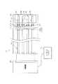
図1は、ロボット10のアーム11及び操作装置30を示す斜視図である。 FIG. 1 is a perspective view showing an
ロボット10は、垂直多関節型のロボットであり、6つ(複数)の関節を有するアーム11を備えている。アーム11の各関節には、それぞれモータが設けられており、これらのモータの回転によりアーム11が駆動される。各モータには、その出力軸を制動する電磁ブレーキと、出力軸の回転角度に応じたパルス信号を出力するエンコーダとがそれぞれ設けられている。ロボット10は、アーム11を動作させることにより、ワークに対する部品の組付けやワークの搬送等の作業を行う。 The
アーム11は、回転部11a及びハンド部11bを有している。回転部11aの先端部には、ハンド部11bが設けられている。ハンド部11bは、軸線J1を回転中心として、回転部11aに対して回転可能になっている。 The
回転部11aには、軸線J1と同軸状に挿入孔12aが形成されている。ハンド部11bには、中心軸に垂直な軸線J2と同軸状に挿入孔12bが形成されている。なお、挿入孔12a及び挿入孔12bの一方を省略することもできる。 An
操作装置30は、本体31、レバー34、挿入部37を備えている。 The operating
本体31は、楕円柱状(棒状)に形成されており、作業者の手で把持可能な大きさとなっている。本体31の表面には、長手方向に所定の間隔をおいて周方向に延びる凹部31aが形成されている。この所定の間隔は、作業者の標準的な指の間隔に対応している。これらの凹部31aによって、作業者の手で把持される被把持部が構成されている。 The
本体31の長手方向の一端部31bにおいて本体31の側部には、所定の大きさの曲線状のレバー34が設けられている。この所定の大きさは、通常の作業者が人差し指及び中指で押すことのできる大きさに設定されている。レバー34(可動部材)は、本体31の長手方向に対して所定の角度をなしており、本体31の長手方向に交差するように本体31から突出している。レバー34は、本体31側の端部を中心として本体31の内部方向へ揺動可能となっている。これにより、作業者は、本体31の側方から、レバー34を人差し指及び中指で引くことが可能となっている。レバー34は、作業者の手の人差し指及び中指で引かれる(押される)ことにより、動かされていない状態の第1位置、中間位置まで動かされた状態の第2位置、及び中間位置を越えて動かされた状態の第3位置に切替可能(移動可能)となっている。 A
本体31には、本体31の長手方向においてレバー34よりも両外側(図1では上側及び下側)から本体31の側方へ延びて、レバー34の正面側(本体31の側方側)を覆うガード部32が形成されている。ガード部32(覆い部)は、環状(弧状)に形成されており、本体31の周方向に開口している。ガード部32の内部にレバー34収容されており、ガード部32とレバー34との間には所定の隙間が形成されている。これにより、作業者はレバー34の上部とガード部32との間に人差し指及び中指を挿入することができるとともに、レバー34の揺動がガード部32によって妨げられることはない。 The
本体31の長手方向においてレバー34が設けられた側の一端部31bには、挿入部37が取り付けられている。すなわち、レバー34及び挿入部37は、本体31の長手方向において同じ側の一端部31bに設けられている。挿入部37(被取付部)は、円柱状に形成されており、その一端部が本体31に取り付けられたピン33により回転可能に支持されている。すなわち、挿入部37は、ピン33(本体31との連結部)を中心として、本体31に対して揺動可能となっている。挿入部37は、挿入孔12a,12bに挿入可能に形成されている。 An
図2は、ロボット10の制御装置20とイネーブルスイッチ40との接続を示す模式図である。 FIG. 2 is a schematic view showing the connection between the
ロボット10は、制御装置20に接続されている。制御装置20は、CPU、ROM、RAM、記憶装置、駆動回路、位置検出回路等を備えている。ROMは、ロボット10のシステムプログラムや動作プログラム等を記憶している。RAMは、これらのプログラムを実行する際にパラメータの値等を記憶する。位置検出回路には、各エンコーダの検出信号がそれぞれ入力される。位置検出回路は、各エンコーダの検出信号に基づいて、各関節に設けられたモータの回転角度を検出する。CPUは、予め設定された動作プログラム(プログラム)を実行することにより、位置検出回路から入力される位置情報に基づいて、アーム11の各関節の回転角度(アーム11の姿勢)を目標回転角度(目標姿勢)にフィードバック制御する。 The
制御装置20には、ティーチングペンダント70が接続されている。ティーチングペンダント70(操作機)は、CPU、ROM、及びRAMを含むマイクロコンピュータ、各種の手動操作キー、ディスプレイ等を備えている。作業者は、このペンダント70を手動操作して、ロボット10の動作プログラムの作成、修正、登録、各種パラメータの設定を行うことができる。動作プログラムの修正等を行うティーチングでは、作業においてアーム11のハンド部11bが通過する教示点(位置座標)を、作業者が操作装置30を用いて直接教示する。そして、作業者は、制御装置20を通じて、ティーチングされた動作プログラムに基づきロボット10を動作させることができる。 A
本体31には、イネーブルスイッチ40及び非常停止スイッチ44が組み込まれている。イネーブルスイッチ40は、オフとオンとオフとの3位置に切り替えられるものである。イネーブルスイッチ40は、上記レバー34の位置が第1位置及び第3位置でオフとなり、レバー34の位置が第2位置でオンとなる。非常停止スイッチ44は、常閉式のスイッチであり、非常停止ボタン35が押されることにより開状態となる。非常停止ボタン35は、本体31に設けられている(図1では図示せず)。イネーブルスイッチ40の回路38、及び非常停止スイッチ44の回路39は、挿入部37の出力部37a(端子)に接続されている。 The
制御装置20から挿入孔12a,12bまで、ロボット10のアーム11を介して回路14が接続されている。そして、挿入孔12a又は挿入孔12bに挿入部37が挿入されることにより、出力部37aがアーム11内の回路14に接続される。すなわち、アーム11に挿入部37(操作装置30)が取り付けられることにより、スイッチ40,44の回路38,39が制御装置20に接続される。このため、制御装置20は、挿入部37の出力部37aを介して、イネーブルスイッチ40の状態を把握することができる。制御装置20は、イネーブルスイッチ40がオン位置である場合にのみ、ロボット10のアーム11の動作を許可する。なお、アーム11には、挿入孔12a,12bに挿入された挿入部37をロックするロック機構(図示せず)が設けられている。 The circuit 14 is connected from the
次に、ロボット10のダイレクトティーチングにおいて、操作装置30を用いてロボット10のアーム11を操作する方法について説明する。 Next, in direct teaching of the
まず、作業者は、アーム11の挿入孔12a又は挿入孔12bに操作装置30の挿入部37を挿入して、ロック機構により挿入部37をロックする。これにより、アーム11に挿入部37(操作装置30)が取り付けられる。このとき、挿入孔12a又は挿入孔12bに挿入部37が挿入されることにより、イネーブルスイッチ40及び非常停止スイッチ44が制御装置20に接続される(取付工程)。なお、スイッチ40,44と制御装置20との接続は、ティーチングペンダント70の操作キーが「Auto Mode」から「Manual Mode」に切り替えられている場合に有効となる。 First, the worker inserts the
また、作業者は、アーム11に挿入部37を取り付ける前又は取り付けた後に、本体31に対して挿入部37を揺動させて、アーム11と本体31との角度を調節する(角度調節工程)。 Before or after attaching the
上記取付工程の後、図1,3に示すように、作業者は、本体31を手の人差し指及び中指以外の3本の指で把持し、人差し指及び中指をレバー34の上部とガード部32との間に通して、レバー34を人差し指及び中指で第2位置まで揺動させて維持する(動作許可工程)。詳しくは、作業者は、小指、薬指及び親指で本体31の各凹部31aを握るとともに、本体31の側方からレバー34を人差し指及び中指で引いて維持する。なお、アーム11側には、手の小指側ではなく親指側が位置することとなる。これにより、イネーブルスイッチ40がオン位置となり、制御装置20によりロボット10のアーム11の動作が許可される。この動作許可状態では、制御装置20は、アーム11に重力に抗するだけの駆動力を付与し、アーム11に作用するその他の力によりアーム11が自由に移動されるようにする。 After the attaching process, as shown in FIGS. 1 and 3, the operator holds the
上記動作許可工程の後、作業者は本体31に力を加えてアーム11を操作する(操作工程)。このとき、作業者は、主に人差し指及び中指以外の3本の指により本体31に力を加えてアーム11を操作し、人差し指及び中指によりレバー34を第2位置に維持する。 After the operation permission process, the operator applies a force to the
以上詳述した本実施形態は、以下の利点を有する。 The embodiment described above has the following advantages.
・動作許可工程において、作業者は、本体31を手の人差し指及び中指以外の3本の指で把持し、レバー34を人差し指及び中指で第2位置まで動かして維持する。これにより、イネーブルスイッチ40がオン位置となり、ロボット10の動作が許可される。ここで、レバー34は、本体31の長手方向の一端部31bにおいて本体31の側部に所定の大きさで設けられ、本体31の内部方向へ引かれることにより第1位置から第3位置まで動かされる。このため、作業者は、操作装置30の本体31を手の人差し指及び中指以外の3本の指で把持しつつ、レバー34を人差し指及び中指で第2位置まで容易に動かすことができる。 In the operation permitting step, the operator holds the
・操作工程において、作業者は、操作装置30の本体31に力を加えてアーム11を操作する。このとき、主に人差し指及び中指以外の3本の指により本体31に力を加えてロボット10のアーム11を操作し、人差し指及び中指によりレバー34を第2位置で容易に維持することができる。すなわち、本体31を把持してアーム11を操作する力と、イネーブルスイッチ40のレバー34を引く力とを分離することができる。したがって、作業者が操作装置30によりロボット10のアーム11を操作する際に、イネーブルスイッチ40が意図せずオフに切り替わることを抑制することができ、アーム11の操作性が低下することを抑制することができる。 In the operation process, the operator applies a force to the
・レバー34は、本体31の長手方向に交差するように本体31から突出しており、本体31側の端部を中心として揺動可能である。動作許可工程において、作業者は本体31の側方から、レバー34を人差し指及び中指で引いて維持する。このため、人差し指及び中指の自然な動きによりレバー34を引くことができ、アーム11の操作性を向上させることができる。さらに、緊急時において、素早くレバー34を引くことができる。また、右手と左手のいずれでも、操作装置30を操作することができる。 The
・本体31には、本体31の長手方向においてレバー34よりも両外側から本体31の側方へ延びて、レバー34の正面側を覆うガード部32が設けられている。動作許可工程において、作業者は手の人差し指及び中指を、レバー34とガード部32との間に通す。したがって、ガード部32によって人差し指及び中指が他の指から隔てられるため、本体31を把持してアーム11を操作する力とレバー34を引く力とを、物理的にも意識的にも分離し易くなる。 The
・挿入部37は、ピン33を中心として、本体31に対して揺動可能となっている。そして、角度調節工程において、本体31に対して挿入部37を揺動させて、アーム11と本体31との角度が調節される。したがって、アーム11の操作性を向上させることができる。 The
・挿入部37及びレバー34は、本体31の長手方向において同じ側の一端部31bに設けられている。このため、挿入部37がロボット10のアーム11に取り付けられた状態で、アーム11側に親指を位置させて本体31を把持することができる。したがって、アーム11側に小指を位置させて本体31を把持する場合と比較して、アーム11の操作性を向上させることができる。 The
・挿入部37はイネーブルスイッチ40に接続されている出力部37aを有しており、アーム11に挿入部37が取り付けられることにより、出力部37aが制御装置20に接続される。このため、制御装置20は、挿入部37の出力部37aを介して、イネーブルスイッチ40の状態を把握することができる。したがって、操作装置30のアーム11への取付と、イネーブルスイッチ40の制御装置20への接続とを一度に行うことができ、作業の効率を向上させることができる。 The
・操作工程において、作業者は、本体31に力を加えてアーム11を操作する際に、手の薬指側部分をガード部32(突出部)に当てることができる。したがって、操作装置30を手の薬指側に移動させる際に、手の一部をガード部32に当てて力を加えることができる。その結果、本体31を強く把持する必要がなくなり、作業者の身体的負担を軽減することができるとともに、アーム11の操作性を向上させることができる。 In the operation step, when the operator applies a force to the
なお、上記実施形態を、以下のように変更して実施することもできる。上記実施形態と同一の部材については、同一の符号を付すことにより説明を省略する。 The above embodiment can be modified as follows. About the same member as the above-mentioned embodiment, explanation is omitted by attaching the same numerals.
・本体31は、楕円柱状に限らず、円柱状や四角柱状等、任意の柱状(棒状)にすることができる。 The
・図4に示すように、凹部31a側から挿入部37側へ延びるレバー134を採用することもできる。この場合も、レバー134(可動部材)は、本体31側の端部を中心として揺動可能となっている。そして、レバー134は、作業者の手の人差し指及び中指で引かれる(押される)ことにより、動かされていない状態の第1位置、中間位置まで動かされた状態の第2位置、及び中間位置を越えて動かされた状態の第3位置に切替可能(移動可能)となっている。 -As shown in FIG. 4, the
・上記レバー34,134に代えて、図5に示すように、所定の大きさの矩形板状のボタン234を採用することもできる。ボタン234(可動部材)も、作業者の手の人差し指及び中指で本体31の内部方向へ押されることにより、第1位置から第3位置まで切替可能(移動可能)となっている。また、本体31の長手方向においてボタン234の中間部には、凹部234a,234bが形成されている。そして、動作許可工程において、作業者は凹部234a,234bに人差し指及び中指をそれぞれ載せて、本体31の側方からボタン234を人差し指及び中指で押し込んで維持する。このため、人差し指及び中指がボタン234から外れることを抑制することができ、アーム11の操作性を向上させることができる。なお、凹部234a,234bの一方又は双方を省略することもできる。また、ボタン234は、矩形板状に限らず、円板状等、人差し指及び中指で押すことが可能な任意の形状にすることができる。 In place of the
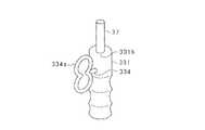
・上記レバー34,134に代えて、図6に示すように、所定の大きさのトリガ334(可動部材)を採用することもできる。トリガ334は、本体331の周方向に開口した環状部334aを有し、本体331の内部方向へ押し込まれることにより第1位置から第3位置まで移動する。そして、動作許可工程において、作業者は環状部334aに人差し指及び中指を通して、本体331の側方からトリガ334を人差し指及び中指で引いて維持する。このため、人差し指及び中指がトリガ334から外れることを抑制することができ、アーム11の操作性を向上させることができる。さらに、環状部334aによって人差し指及び中指が他の指から隔てられるため、本体331を把持してアーム11を操作する力とトリガ334を引く力とを、物理的にも意識的にも分離し易くなる。なお、環状部334aは、人差し指及び中指を1つの孔に通すことのできるものでもよいし、人差し指及び中指を個別の孔にそれぞれ通すことのできるものでもよい。また、挿入部37の一端部は、本体331においてトリガ334が設けられた側の一端部331bに固定されている。 Instead of the
・図7に示すように、本体431の長手方向においてレバー34を除く部分の両端部に、長手方向に直交(交差)するように本体431から突出する突出部431c,431dをそれぞれ設けてもよい。この場合、本体431において突出部431c,431d同士の間の部分が、作業者により把持される被把持部431eとなっている。 As shown in FIG. 7,
こうした構成によれば、作業者が被把持部431eを把持した場合に、手の薬指側部分及び小指側部分を突出部431c,431dにそれぞれ当てることができる。したがって、操作装置430を手の薬指側及び小指側のいずれに移動させる際にも、手の一部を突出部431c,431dに当てて力を加えることができる。その結果、本体431を強く把持する必要がなくなり、作業者の身体的負担を軽減することができるとともに、アーム11の操作性を向上させることができる。なお、突出部431c,431dの一方を省略することもできる。その場合であっても、操作工程において、作業者は、本体431に力を加えてアーム11を操作する際に、手の薬指側部分及び小指側部分の少なくとも一方を突出部431c又は突出部431dに当てることができる。 According to such a configuration, when the operator grips the gripped
また、操作装置430は、アーム11に取り付けられる吸盤437(被取付部)を備えている。そして、コード438により、イネーブルスイッチ40が制御装置20に接続されている。この場合に、イネーブルスイッチ40は、オン又はオフであることを示す信号を制御装置20へ送信してもよい。また、イネーブルスイッチ40は、オン又はオフであることを示す信号を、無線により制御装置20へ送信することもできる。すなわち、イネーブルスイッチ40と制御装置20とは、無線接続されていてもよい。 The operating
・図8に示すように、操作装置530は、アーム11に取り付けられるフランジ537(被取付部)を備えていてもよい。フランジ537には、ねじ孔537bが形成されており、このねじ孔537bにねじを挿通してフランジ537をアーム11に締結することができる。 As shown in FIG. 8, the operating
また、イネーブルスイッチ40に接続されたピン537a(出力部)が、フランジ537に設けられている。そして、アーム11にフランジ537に締結することにより、ピン537aが制御装置20に接続される。こうした構成によれば、操作装置530をより確実にアーム11に取り付けることができるとともに、イネーブルスイッチ40と制御装置20との接続を安定させることができる。 Also, a pin 537 a (output unit) connected to the enable switch 40 is provided on the
・上記実施形態では、ロボット10のダイレクトティーチングにおいて操作装置30を用いたが、ロボット10の作業中にアーム11のハンド部11bをガイドするハンドガイドにおいて操作装置30を用いることもできる。この場合、挿入部37等(被取付部)に作業者による操作力の大きさ及び方向を検知する操作力センサを取り付け、操作力センサの出力に基づいてアーム11を動作させるようにしてもよい。 In the embodiment described above, the operating
10…ロボット、11…アーム、20…制御装置、30…操作装置、31…本体、31b…一端部、32…ガード部(覆い部、突出部)、34…レバー(可動部材)、37…挿入部(被取付部)、37a…出力部、40…イネーブルスイッチ、134…レバー(可動部材)、234…ボタン(可動部材)、234a…凹部、234b…凹部、331…本体、331b…一端部、334…トリガ(可動部材)、334a…環状部、430…操作装置、431…本体、431c…突出部、431d…突出部、431e…被把持部、437…吸盤(被取付部)、530…操作装置、537…フランジ(被取付部)、537a…ピン(出力部)。 DESCRIPTION OF
Claims (15)
Translated fromJapanese前記操作装置は、
前記作業者の手で把持可能な棒状の本体と、
前記アームに取り付けられる被取付部と、
前記ロボットの制御装置に接続され、動かされていない状態の第1位置、中間位置まで動かされた状態の第2位置、及び前記中間位置を越えて動かされた状態の第3位置に移動可能な可動部材を有し、前記可動部材の位置が前記第1位置及び前記第3位置でオフとなり、前記第2位置でオンとなるイネーブルスイッチと、
を備え、
前記可動部材は、前記本体の長手方向の一端部において前記本体の側部に所定の大きさで設けられ、前記本体の内部方向へ押されることにより前記第1位置から前記第3位置まで移動するものであり、
前記被取付部及び前記可動部材は、前記本体の長手方向において同じ側の端部に設けられており、
前記アームに前記被取付部を取り付け、前記イネーブルスイッチを前記制御装置に接続する取付工程と、
前記取付工程の後に、前記作業者が前記本体を手の人差し指及び中指以外の3本の指で把持し、前記可動部材を人差し指及び中指で前記第2位置まで押して維持する動作許可工程と、
前記動作許可工程の後に、前記作業者が前記本体に力を加えて前記アームを操作する操作工程と、
を備えることを特徴とするアームの操作方法。A method in which an operator applies a force to an operating device to operate an arm of a robot,
The operating device is
A rod-like main body that can be gripped by the worker's hand,
A mounting portion attached to the arm;
It is connected to the control device of the robot and can be moved to a first position in a non-moving state, a second position in a moved state to an intermediate position, and a third position in a moved state beyond the intermediate position. An enable switch having a movable member, the position of the movable member being turned off at the first position and the third position, and turned on at the second position;
Equipped with
The movable member is provided in a predetermined size at a side portion of the main body at one end in the longitudinal direction of the main body, and moves from the first position to the third position by being pushed inward of the main body. And
The attached portion and the movable member are provided at the same end in the longitudinal direction of the main body,
Attaching the attached portion to the arm and connecting the enable switch to the control device;
An operation permitting step in which the operator holds the main body with three fingers other than the forefinger and the middle finger after the attaching step, and presses the movable member to the second position with the forefinger and the middle finger to maintain the movable member;
After the operation permitting step, an operation step in which the operator applies a force to the main body to operate the arm;
A method of operating an arm comprising:
前記動作許可工程は、前記作業者が前記本体の側方から、前記可動部材を人差し指及び中指で引いて維持する工程を含む請求項1に記載のアームの操作方法。The movable member protrudes from the main body so as to intersect the longitudinal direction of the main body, and is swingable around an end on the main body side,
The method for operating an arm according to claim 1, wherein the operation permitting step includes the step of the operator pulling and maintaining the movable member with a forefinger and a middle finger from the side of the main body.
前記動作許可工程は、前記作業者が前記凹部に人差し指及び中指の少なくとも一方を載せて、前記本体の側方から前記可動部材を人差し指及び中指で押し込んで維持する工程を含む請求項1に記載のアームの操作方法。The movable member has a recess formed at an intermediate portion, and is moved from the first position to the third position by being pushed toward the inside of the main body,
The operation permission step includes the step of placing the at least one of the forefinger and the middle finger in the recess and keeping the movable member pressed from the side of the main body with the forefinger and the middle finger. How to operate the arm.
前記動作許可工程は、前記作業者が手の人差し指及び中指を、前記可動部材と前記覆い部との間に通す工程を含む請求項1〜3のいずれか1項に記載のアームの操作方法。The main body is provided with a covering portion which extends from the outer side of the movable member to the side of the main body in the longitudinal direction of the main body and covers the lateral side of the movable member.
The method of operating an arm according to any one of claims 1 to 3, wherein the operation permitting step includes the step of the worker passing a forefinger and a middle finger of a hand between the movable member and the cover.
前記動作許可工程は、前記作業者が前記環状部に人差し指及び中指を通して、前記本体の側方から前記可動部材を人差し指及び中指で押し込んで維持する工程を含む請求項1に記載のアームの操作方法。The movable member has an annular portion opened in the circumferential direction of the main body, and is moved from the first position to the third position by being pushed in the inner direction of the main body,
The method according to claim 1, wherein the operation permission step includes the step of the operator passing the forefinger and the middle finger through the annular portion and pressing the movable member from the side of the main body with the forefinger and the middle finger and maintaining the arm. .
前記操作工程は、前記作業者が手の薬指側部分及び小指側部分の少なくとも一方を前記突出部に当てる工程を含む請求項1〜5のいずれか1項に記載のアームの操作方法。At least one end of the portion excluding the movable member in the longitudinal direction of the main body is provided with a protrusion which protrudes from the main body so as to intersect the longitudinal direction,
The method of operating an arm according to any one of claims 1 to 5, wherein the operation step includes the step of the operator applying at least one of the ring finger side portion and the little finger side portion of the hand to the projection.
前記本体に対して前記被取付部を揺動させて、前記アームと前記本体との角度を調節する工程を備える請求項1〜6のいずれか1項に記載のアームの操作方法。The attached portion is pivotable relative to the main body about a connecting portion with the main body,
The method of operating an arm according to any one of claims 1 to 6, further comprising: a step of swinging the attached portion with respect to the main body to adjust an angle between the arm and the main body.
ロボットのアームに取り付けられる被取付部と、
前記ロボットの制御装置に接続され、動かされていない状態の第1位置、中間位置まで動かされた状態の第2位置、及び前記中間位置を越えて動かされた状態の第3位置に移動可能な可動部材を有し、前記可動部材の位置が前記第1位置及び前記第3位置でオフとなり、前記第2位置でオンとなるイネーブルスイッチと、
を備え、
前記可動部材は、前記本体の長手方向の一端部において前記本体の側部に通常の作業者が人差し指及び中指で押すことのできる所定の大きさで設けられ、前記人差し指及び前記中指のみにより前記本体の内部方向へ押されることにより前記第1位置から前記第3位置まで移動するものであり、
前記被取付部及び前記可動部材は、前記本体の長手方向において同じ側の端部に設けられていることを特徴とするアームの操作装置。The rod-like main bodygripped by the three fingers other than the index finger and the middle finger of the worker's hand,
A mounting portion attached to a robot arm;
It is connected to the control device of the robot and can be moved to a first position in a non-moving state, a second position in a moved state to an intermediate position, and a third position in a moved state beyond the intermediate position. An enable switch having a movable member, the position of the movable member being turned off at the first position and the third position, and turned on at the second position;
Equipped with
The movable member is provided at a side portion of the main body at one end in the longitudinal direction of the main body in a predetermined size thatcan be pushed by anormal worker with the forefinger and the middlefinger, and the main body isonly by the forefinger and the middle finger Is moved from the first position to the third position by being pushed in the inward direction ofthe
The attached device and the movable member are provided at the same end in the longitudinal direction of the main body .
前記アームに前記被取付部が取り付けられることにより、前記出力部が前記制御装置に接続される請求項8〜14のいずれか1項に記載のアームの操作装置。The attached portion has an output portion connected to the enable switch,
The operating device for an arm according to any one of claims 8 to14 , wherein the output portion is connected to the control device by attaching the attached portion to the arm.
Priority Applications (1)
| Application Number | Priority Date | Filing Date | Title |
|---|---|---|---|
| JP2013062712AJP6527657B2 (en) | 2013-03-25 | 2013-03-25 | Arm operating method and operating device |
Applications Claiming Priority (1)
| Application Number | Priority Date | Filing Date | Title |
|---|---|---|---|
| JP2013062712AJP6527657B2 (en) | 2013-03-25 | 2013-03-25 | Arm operating method and operating device |
Publications (2)
| Publication Number | Publication Date |
|---|---|
| JP2014184540A JP2014184540A (en) | 2014-10-02 |
| JP6527657B2true JP6527657B2 (en) | 2019-06-05 |
Family
ID=51832604
Family Applications (1)
| Application Number | Title | Priority Date | Filing Date |
|---|---|---|---|
| JP2013062712AActiveJP6527657B2 (en) | 2013-03-25 | 2013-03-25 | Arm operating method and operating device |
Country Status (1)
| Country | Link |
|---|---|
| JP (1) | JP6527657B2 (en) |
Family Cites Families (14)
| Publication number | Priority date | Publication date | Assignee | Title |
|---|---|---|---|---|
| DE4024524A1 (en)* | 1990-08-02 | 1992-02-06 | Iveco Magirus | ONE-HAND OPERATING LEVER WITH DEAD MAN CONTROL TO CONTROL A RESCUE BASKET, ESPECIALLY A RESCUE VEHICLE |
| JP3961755B2 (en)* | 2000-09-18 | 2007-08-22 | Idec株式会社 | Grip-type switch device |
| JP2004303728A (en)* | 2003-03-17 | 2004-10-28 | Idec Izumi Corp | Single hand operation device |
| JP4562576B2 (en)* | 2004-07-01 | 2010-10-13 | 富士通コンポーネント株式会社 | Key switch device, keyboard and key switch assembly jig |
| US20060079879A1 (en)* | 2004-10-08 | 2006-04-13 | Faller Craig N | Actuation mechanism for use with an ultrasonic surgical instrument |
| EP1987406B1 (en)* | 2006-02-23 | 2010-08-04 | Abb Ab | A system for controlling the position and orientation of an object in dependence on received forces and torques from a user |
| JP2009077456A (en)* | 2007-08-31 | 2009-04-09 | Mk Seiko Co Ltd | Motor overheating prevention method and electric scissors using the same |
| JP5326589B2 (en)* | 2009-01-14 | 2013-10-30 | トヨタ自動車株式会社 | Robot apparatus and operation method thereof |
| JP5363850B2 (en)* | 2009-03-23 | 2013-12-11 | 株式会社タダノ | Operation machine control lever device |
| JP5547457B2 (en)* | 2009-11-20 | 2014-07-16 | 旭光電機株式会社 | Motion input device |
| US8606403B2 (en)* | 2010-12-14 | 2013-12-10 | Harris Corporation | Haptic interface handle with force-indicating trigger mechanism |
| JP2013062711A (en)* | 2011-09-14 | 2013-04-04 | Nec Casio Mobile Communications Ltd | Photographing device, photographed image processing method, and program |
| JP2013062713A (en)* | 2011-09-14 | 2013-04-04 | Olympus Corp | Imaging apparatus and imaging system |
| JP5507515B2 (en)* | 2011-09-14 | 2014-05-28 | 富士フイルム株式会社 | Non-reversible compression apparatus, operation control method thereof, and operation control program thereof |
- 2013
- 2013-03-25JPJP2013062712Apatent/JP6527657B2/enactiveActive
Also Published As
| Publication number | Publication date |
|---|---|
| JP2014184540A (en) | 2014-10-02 |
Similar Documents
| Publication | Publication Date | Title |
|---|---|---|
| CN103747759B (en) | manipulator system | |
| US20190224855A1 (en) | Robot operating apparatus provided with handles for operating robot | |
| JP2005511334A5 (en) | ||
| US20160090165A1 (en) | Marine propulsion device | |
| JPH07246578A (en) | Master hand device | |
| JP2019533267A5 (en) | ||
| JP6527658B2 (en) | Arm operating method and operating device | |
| JP2009119593A (en) | Hand-held power tool device | |
| JP2020005866A5 (en) | ||
| CN106998649A (en) | Garden Tool Gripping Device | |
| KR20180083404A (en) | Manipulators for manipulating or programming manipulators | |
| JP6527654B2 (en) | Arm operating method and operating device | |
| JP2017170586A5 (en) | ||
| BR102017011471B1 (en) | VEHICLE MAIN SWITCH AND VEHICLE EQUIPPED WITH THE SAME | |
| JP6527657B2 (en) | Arm operating method and operating device | |
| JP6527655B2 (en) | Arm operating method and operating device | |
| JP6527656B2 (en) | Arm operating method and operating device | |
| WO2008100870A3 (en) | Control inceptor systems and associated methods | |
| JP5446573B2 (en) | Robot control apparatus and robot operation device | |
| KR102059534B1 (en) | Robotic arm | |
| JP4454674B2 (en) | Screw tightening device | |
| WO2002061779A1 (en) | Enable switch | |
| EP2990163B1 (en) | Electric power tool | |
| JP5062424B2 (en) | Robot control system | |
| KR101091254B1 (en) | Operation handle |
Legal Events
| Date | Code | Title | Description |
|---|---|---|---|
| A621 | Written request for application examination | Free format text:JAPANESE INTERMEDIATE CODE: A621 Effective date:20160210 | |
| A977 | Report on retrieval | Free format text:JAPANESE INTERMEDIATE CODE: A971007 Effective date:20161124 | |
| A131 | Notification of reasons for refusal | Free format text:JAPANESE INTERMEDIATE CODE: A131 Effective date:20161206 | |
| A521 | Request for written amendment filed | Free format text:JAPANESE INTERMEDIATE CODE: A523 Effective date:20170201 | |
| A02 | Decision of refusal | Free format text:JAPANESE INTERMEDIATE CODE: A02 Effective date:20170425 | |
| A521 | Request for written amendment filed | Free format text:JAPANESE INTERMEDIATE CODE: A523 Effective date:20170719 | |
| A911 | Transfer to examiner for re-examination before appeal (zenchi) | Free format text:JAPANESE INTERMEDIATE CODE: A911 Effective date:20170727 | |
| A912 | Re-examination (zenchi) completed and case transferred to appeal board | Free format text:JAPANESE INTERMEDIATE CODE: A912 Effective date:20170818 | |
| A61 | First payment of annual fees (during grant procedure) | Free format text:JAPANESE INTERMEDIATE CODE: A61 Effective date:20190513 | |
| R150 | Certificate of patent or registration of utility model | Ref document number:6527657 Country of ref document:JP Free format text:JAPANESE INTERMEDIATE CODE: R150 | |
| R250 | Receipt of annual fees | Free format text:JAPANESE INTERMEDIATE CODE: R250 | |
| R250 | Receipt of annual fees | Free format text:JAPANESE INTERMEDIATE CODE: R250 | |
| R250 | Receipt of annual fees | Free format text:JAPANESE INTERMEDIATE CODE: R250 | |
| R250 | Receipt of annual fees | Free format text:JAPANESE INTERMEDIATE CODE: R250 |