JP6525222B2 - Floor vacuum cleaner - Google Patents
Floor vacuum cleanerDownload PDFInfo
- Publication number
- JP6525222B2 JP6525222B2JP2017563375AJP2017563375AJP6525222B2JP 6525222 B2JP6525222 B2JP 6525222B2JP 2017563375 AJP2017563375 AJP 2017563375AJP 2017563375 AJP2017563375 AJP 2017563375AJP 6525222 B2JP6525222 B2JP 6525222B2
- Authority
- JP
- Japan
- Prior art keywords
- water tank
- chamber
- water
- vent
- floor
- Prior art date
- Legal status (The legal status is an assumption and is not a legal conclusion. Google has not performed a legal analysis and makes no representation as to the accuracy of the status listed.)
- Active
Links
Images


Classifications
- A—HUMAN NECESSITIES
- A47—FURNITURE; DOMESTIC ARTICLES OR APPLIANCES; COFFEE MILLS; SPICE MILLS; SUCTION CLEANERS IN GENERAL
- A47L—DOMESTIC WASHING OR CLEANING; SUCTION CLEANERS IN GENERAL
- A47L11/00—Machines for cleaning floors, carpets, furniture, walls, or wall coverings
- A47L11/40—Parts or details of machines not provided for in groups A47L11/02 - A47L11/38, or not restricted to one of these groups, e.g. handles, arrangements of switches, skirts, buffers, levers
- A47L11/4013—Contaminants collecting devices, i.e. hoppers, tanks or the like
- A47L11/4016—Contaminants collecting devices, i.e. hoppers, tanks or the like specially adapted for collecting fluids
- A47L11/4019—Fill level sensors; Security means to prevent overflow, e.g. float valves
- A—HUMAN NECESSITIES
- A47—FURNITURE; DOMESTIC ARTICLES OR APPLIANCES; COFFEE MILLS; SPICE MILLS; SUCTION CLEANERS IN GENERAL
- A47L—DOMESTIC WASHING OR CLEANING; SUCTION CLEANERS IN GENERAL
- A47L11/00—Machines for cleaning floors, carpets, furniture, walls, or wall coverings
- A47L11/26—Floor-scrubbing machines, hand-driven
- A—HUMAN NECESSITIES
- A47—FURNITURE; DOMESTIC ARTICLES OR APPLIANCES; COFFEE MILLS; SPICE MILLS; SUCTION CLEANERS IN GENERAL
- A47L—DOMESTIC WASHING OR CLEANING; SUCTION CLEANERS IN GENERAL
- A47L11/00—Machines for cleaning floors, carpets, furniture, walls, or wall coverings
- A47L11/29—Floor-scrubbing machines characterised by means for taking-up dirty liquid
- A47L11/30—Floor-scrubbing machines characterised by means for taking-up dirty liquid by suction
- A47L11/302—Floor-scrubbing machines characterised by means for taking-up dirty liquid by suction having rotary tools
- A—HUMAN NECESSITIES
- A47—FURNITURE; DOMESTIC ARTICLES OR APPLIANCES; COFFEE MILLS; SPICE MILLS; SUCTION CLEANERS IN GENERAL
- A47L—DOMESTIC WASHING OR CLEANING; SUCTION CLEANERS IN GENERAL
- A47L11/00—Machines for cleaning floors, carpets, furniture, walls, or wall coverings
- A47L11/40—Parts or details of machines not provided for in groups A47L11/02 - A47L11/38, or not restricted to one of these groups, e.g. handles, arrangements of switches, skirts, buffers, levers
- A47L11/4013—Contaminants collecting devices, i.e. hoppers, tanks or the like
- A47L11/4016—Contaminants collecting devices, i.e. hoppers, tanks or the like specially adapted for collecting fluids
- A—HUMAN NECESSITIES
- A47—FURNITURE; DOMESTIC ARTICLES OR APPLIANCES; COFFEE MILLS; SPICE MILLS; SUCTION CLEANERS IN GENERAL
- A47L—DOMESTIC WASHING OR CLEANING; SUCTION CLEANERS IN GENERAL
- A47L11/00—Machines for cleaning floors, carpets, furniture, walls, or wall coverings
- A47L11/40—Parts or details of machines not provided for in groups A47L11/02 - A47L11/38, or not restricted to one of these groups, e.g. handles, arrangements of switches, skirts, buffers, levers
- A47L11/4063—Driving means; Transmission means therefor
- A47L11/4069—Driving or transmission means for the cleaning tools
- A—HUMAN NECESSITIES
- A47—FURNITURE; DOMESTIC ARTICLES OR APPLIANCES; COFFEE MILLS; SPICE MILLS; SUCTION CLEANERS IN GENERAL
- A47L—DOMESTIC WASHING OR CLEANING; SUCTION CLEANERS IN GENERAL
- A47L11/00—Machines for cleaning floors, carpets, furniture, walls, or wall coverings
- A47L11/40—Parts or details of machines not provided for in groups A47L11/02 - A47L11/38, or not restricted to one of these groups, e.g. handles, arrangements of switches, skirts, buffers, levers
- A47L11/4077—Skirts or splash guards
- A—HUMAN NECESSITIES
- A47—FURNITURE; DOMESTIC ARTICLES OR APPLIANCES; COFFEE MILLS; SPICE MILLS; SUCTION CLEANERS IN GENERAL
- A47L—DOMESTIC WASHING OR CLEANING; SUCTION CLEANERS IN GENERAL
- A47L11/00—Machines for cleaning floors, carpets, furniture, walls, or wall coverings
- A47L11/40—Parts or details of machines not provided for in groups A47L11/02 - A47L11/38, or not restricted to one of these groups, e.g. handles, arrangements of switches, skirts, buffers, levers
- A47L11/408—Means for supplying cleaning or surface treating agents
- A47L11/4083—Liquid supply reservoirs; Preparation of the agents, e.g. mixing devices
- A—HUMAN NECESSITIES
- A47—FURNITURE; DOMESTIC ARTICLES OR APPLIANCES; COFFEE MILLS; SPICE MILLS; SUCTION CLEANERS IN GENERAL
- A47L—DOMESTIC WASHING OR CLEANING; SUCTION CLEANERS IN GENERAL
- A47L11/00—Machines for cleaning floors, carpets, furniture, walls, or wall coverings
- A47L11/40—Parts or details of machines not provided for in groups A47L11/02 - A47L11/38, or not restricted to one of these groups, e.g. handles, arrangements of switches, skirts, buffers, levers
- A47L11/408—Means for supplying cleaning or surface treating agents
- A47L11/4088—Supply pumps; Spraying devices; Supply conduits
Landscapes
- Cleaning In General (AREA)
- Nozzles For Electric Vacuum Cleaners (AREA)
- Electric Vacuum Cleaner (AREA)
- Cleaning By Liquid Or Steam (AREA)
- Cleaning Implements For Floors, Carpets, Furniture, Walls, And The Like (AREA)
Description
Translated fromJapanese本願は、掃除装置に関し、特に床面掃除機の給水構造に関する。 The present application relates to a cleaning device, and more particularly to a water supply structure of a floor cleaner.
人間が初期に使用していた床面掃除用具は、主に人間の手動操作により掃除作業を行う箒、モップ、フロアワイパーなどである。科学技術の進歩に伴い、人々の床面掃除用具への要求も徐々に高くなり、最初には、電力によりエネルギーを供給し、負圧を生成することにより床面上のごみ、灰塵などを吸引する集塵機が現れている。しかし、集塵機は、その動作原理に制限されるため、床面に強固に付着しているごみと汚れを掃除できないので、新しい床面掃除機も現れている。該新しい床面掃除機は、モータの運転により掃除コラム(掃除ロール)を床面を拭くように駆動するとともに、該床面掃除機内に給水システムも配置されて、掃除コラムを洗浄することにより、床面に対する掃除を完璧に実現する。 The floor cleaning tools that humans initially used are mainly scissors, mops, floor wipers, and the like that perform cleaning operations manually operated by humans. With the advancement of science and technology, people's demand for floor cleaning tools gradually increases, and at first, energy is supplied by electric power and negative pressure is generated to suction dust, ash dust, etc. on the floor Dust collectors are appearing. However, since the dust collector is limited by its operating principle, new floor cleaners have also emerged because the dust and dirt firmly adhering to the floor can not be cleaned. The new floor cleaner drives the cleaning column (cleaning roll) to wipe the floor by the operation of a motor, and a water supply system is also disposed in the floor cleaner to clean the cleaning column, Completely clean the floor.
該給水システムは、掃除コラムの表面と密封的に連通する水槽内に清水を提供することにより、掃除コラムの表面を洗浄する。洗浄後の汚水は給水システムにより汚水タンクに吸引されて、相応の処理を行われる。しかし、従来の構造において、汚水の吸引は、主に集塵機の生成した動力に依存するが、このような動力は、主に集塵機能を満たし、汚水吸引が付加的な機能のみであるので、汚水タンクの汚水回収能力を柔軟に調節することができない。 The water supply system cleans the surface of the cleaning column by providing fresh water in a water tank in sealed communication with the surface of the cleaning column. The dirty water after washing is drawn into the dirty water tank by the water supply system and subjected to the appropriate treatment. However, in the conventional structure, the suction of the sewage mainly depends on the power generated by the dust collector, but such power mainly fulfills the dust collection function and the sewage suction is only an additional function, so the sewage It is not possible to flexibly adjust the sewage recovery capacity of the tank.
本願は新規な床面掃除機を提供する。
本願に係る床面掃除機は、
床面を掃除する掃除コラムと、
掃除コラムの表面に密封的にかけられた水槽と、
清潔な水源を貯蔵する清水タンクと、
前記清水タンクと水槽と互いに連通し、清水タンク内の清水を水槽内に流入させる清水供給装置と、
回収した汚水を貯蔵するチャンバーを有し、前記チャンバーに水槽と連通する汚水流入口と抽気口が開設される汚水タンクと、
吸気口が汚水タンクの抽気口と連通するエアポンプとを含む。The present application provides a novel floor cleaner.
The floor cleaner according to the present invention is
A cleaning column that cleans the floor,
A water tank sealed on the surface of the cleaning column,
Fresh water tank which stores clean water source,
A fresh water supply device which mutually communicates with the fresh water tank and the water tank and causes clean water in the fresh water tank to flow into the water tank;
A sewage tank having a chamber for storing collected sewage, wherein the chamber is provided with a sewage inlet communicating with the water tank and an extraction port;
And an air pump whose intake port communicates with the bleed port of the dirty water tank.
前記床面掃除機の更なる改良として、前記エアポンプの排気口は掃除コラムの表面又は水槽と連通する。 As a further improvement of the floor cleaner, the exhaust port of the air pump communicates with the surface of the cleaning column or a water tank.
前記床面掃除機の更なる改良として、前記汚水タンクのチャンバー内に少なくとも1つの水飛び防止部材が設置され、前記少なくとも1つの水飛び防止部材が汚水タンクのチャンバーを分割して収容チャンバーを形成し、前記収容チャンバーと抽気口が水飛び防止部材により隔てられ、前記水飛び防止部材に収容チャンバーと抽気口とを連通させる通気口が開設され、前記通気口が抽気口と位置ずれして設置される。 As a further improvement of the floor cleaner, at least one anti-flying member is installed in the chamber of the dirty water tank, and the at least one anti-flying member divides the chamber of the dirty water tank to form a storage chamber The storage chamber and the bleed port are separated by a water splash preventing member, and the water splash preventing member is provided with a vent for communicating the storage chamber with the bleed port, and the vent is disposed out of alignment with the bleed slot Be done.
前記床面掃除機の更なる改良として、前記汚水タンクのチャンバー内に水飛び防止部材が設置され、前記水飛び防止部材が第1の緩衝貯蔵チャンバーを有し、前記第1の緩衝貯蔵チャンバーには、上下に設置された第1の通気口と第2の通気口がそれぞれ開設され、前記水飛び防止部材がチャンバー内に取り付けられると、前記チャンバーを分割して第2の緩衝貯蔵チャンバーと収容チャンバーを形成し、前記収容チャンバーが第2の通気口を介して第1の緩衝貯蔵チャンバーと連通し、前記第2の緩衝貯蔵チャンバーが第1の通気口を介して第1の緩衝貯蔵チャンバーと連通し、前記抽気口が第2の緩衝貯蔵チャンバーと連通し、前記抽気口、第1の通気口及び第2の通気口のうちの少なくとも2つが互いに位置ずれして設置される。 As a further improvement of the floor cleaner, a water splash preventing member is installed in a chamber of the dirty water tank, the water splash preventing member has a first buffer storage chamber, and the first buffer storage chamber is The first vent and the second vent installed at the top and the bottom are opened respectively, and when the water splash preventing member is mounted in the chamber, the chamber is divided to accommodate the second buffer storage chamber and the second buffer storage chamber. A chamber is formed, the storage chamber is in communication with the first buffer storage chamber through the second vent, and the second buffer storage chamber is in communication with the first buffer storage chamber through the first vent. In communication, the bleed port communicates with the second buffer storage chamber, and at least two of the bleed port, the first vent and the second vent are offset from one another.
前記床面掃除機の更なる改良として、前記互いに位置ずれして設置されることは、互いに異なる方向に位置する場合と、同じ方向での異なる位置に位置する場合とを含む。
前記床面掃除機の更なる改良として、前記第2の通気口は、収容チャンバーの入口に向かって横方向に沿って設置される。
前記床面掃除機の更なる改良として、前記第1の通気口は縦方向に沿って設置される。As a further improvement of the floor cleaner, the mutually offset installation includes the case of being located in different directions and the case of being located in different positions in the same direction.
As a further refinement of the floor cleaner, the second vent is provided laterally along the inlet of the receiving chamber.
As a further improvement of the floor cleaner, the first vent is provided along the longitudinal direction.
前記床面掃除機の更なる改良として、前記抽気口は横方向に沿って設置される。
前記床面掃除機の更なる改良として、前記汚水タンク内に、さらに、汚水の液面の高さを検出する液位検出装置が取り付けられている。
前記床面掃除機の更なる改良として、前記清水供給装置は、入水口が清水タンクと連通し、出水口が水槽と連通する水ポンプである。As a further improvement of the floor cleaner, the bleed port is installed along the lateral direction.
As a further improvement of the floor cleaner, a liquid level detection device for detecting the level of the liquid surface of the sewage is further installed in the sewage tank.
As a further improvement of the floor cleaner, the fresh water supply device is a water pump whose water inlet communicates with the fresh water tank and whose water outlet communicates with the water tank.
本願は以下のような有益な効果を有する。
本願に係る床面掃除機は、掃除コラム、水槽、清水タンク、清水供給装置、汚水タンク及びエアポンプを含む。該水槽は、掃除コラムの表面に密封的にかけられ、清水タンク、清水供給装置及び水槽は互いに連通し、清水供給装置は、清水タンク内の清水を水槽内に流入させる。汚水タンクは、回収した汚水を貯蔵するチャンバーを有し、チャンバーに汚水流入口と抽気口が開設され、汚水流入口が水槽と連通し、エアポンプの吸気口が汚水タンクの抽気口と連通する。本願は、独立したエアポンプを汚水タンクの汚水吸引のための動力とし、実際の需要に応じて、汚水タンクの汚水回収能力を柔軟に調節することができる。The present application has the following beneficial effects.
The floor cleaner according to the present invention includes a cleaning column, a water tank, a fresh water tank, a fresh water supply device, a dirty water tank and an air pump. The water tank is sealingly placed on the surface of the cleaning column, and the fresh water tank, the fresh water supply device and the water tank communicate with each other, and the fresh water supply device allows the fresh water in the fresh water tank to flow into the water tank. The dirty water tank has a chamber for storing the collected dirty water, the dirty water inlet and the bleed port are opened in the chamber, the dirty water inlet communicates with the water tank, and the air pump inlet communicates with the bleed port of the dirty water tank. In the present application, the independent air pump is used as the power for suctioning the sewage in the sewage tank, and the sewage collection capacity of the sewage tank can be flexibly adjusted according to the actual demand.
以下、具体的な実施形態と図面を合わせて本発明をさらに詳細に説明する。本願は、本実施例に記載の実施形態に限られず、種々の異なる態様で実現することができる。以下の具体的な実施形態は、本願の開示の内容をより明晰かつ徹底的に理解しやすくするために提供したものであり、方向を指示する上、下、左、右などの用語は、示された構造の対応する図面での位置について言ったものにすぎない。 Hereinafter, the present invention will be described in more detail by combining specific embodiments and the drawings. The present application is not limited to the embodiments described in the present embodiment, and can be realized in various different modes. The following specific embodiments are provided to make the content of the present disclosure more clearly and completely understandable, and terms such as upper, lower, left, right, etc., which indicate the direction, are shown It only refers to the position in the corresponding drawing of the structure being constructed.
しかしながら、当業者であれば、そのうちの1つ又は複数の具体的な詳細の記載を省略してもよく、他の方法、アセンブリ又は材料を用いてもよいと意識するべきである。いくつかの例において、いくつかの実施形態は、記述されていないか又は詳細に記述されていない。
また、本明細書に記載の技術的特徴、技術的解決手段は、1つ以上の実施例において、任意の適切な態様で組み合わせてもよい。However, one skilled in the art should be aware that the description of one or more of the specific details may be omitted and that other methods, assemblies or materials may be used. In some instances, some embodiments have not been described or described in detail.
Also, the technical features and technical solutions described herein may be combined in any appropriate manner in one or more embodiments.
本実施例は、床面掃除機を提供する。
該床面掃除機は、ケースアセンブリ、掃除機構、給水機構、制御部及び接続機構を含む。
該ケースアセンブリは、床面掃除機の支持部であり、ベースとハンドルの2つの部分に分けられる。該ベースとハンドルは、接続機構により接続され、ユーザが本床面掃除機をうまく把持してより多くの角度での掃除を実現するために、このような接続は可動である。This embodiment provides a floor cleaner.
The floor cleaner includes a case assembly, a cleaning mechanism, a water supply mechanism, a controller, and a connection mechanism.
The case assembly is a support for a floor cleaner and is divided into two parts, a base and a handle. The base and handle are connected by a connection mechanism, such connection being movable in order for the user to successfully grasp the floor cleaner to achieve cleaning at more angles.
該掃除機構は、床面を掃除するための主な部材であり、一般的にベースに取り付けられている。該給水機構は、清水タンクと汚水タンクを提供し、該清水タンクは、清潔な水源を貯蔵し、掃除機構と連通して動力部材により清水を掃除機構に送って、掃除機構を洗浄する。汚水タンクは、汚水タンクと連通する掃除機構からの汚水を貯蔵する。掃除機構内の汚水は、別の動力部材の作用下で汚水タンクに回収されて、床面掃除機の外部に流出することを回避する。 The cleaning mechanism is a main member for cleaning the floor and is generally attached to the base. The water supply mechanism provides a fresh water tank and a dirty water tank, which stores a clean water source, communicates with the cleaning mechanism, sends clean water to the cleaning mechanism by the power member, and cleans the cleaning mechanism. The dirty water tank stores dirty water from the cleaning mechanism in communication with the dirty water tank. Wastewater in the cleaning mechanism is collected in the waste water tank under the action of another power member to avoid flowing out to the outside of the floor cleaner.
制御部は、主に制御回路と制御回路を支持する回路基板とを含み、他の部分の動作、例えば、掃除機構の運転と停止、給水機構の起動と停止、マンマシン・インタラクションの実現などに対して制御の役割を果たす。
理解しやすくするために、本実施例において、以下、いずれもベース側を前、ハンドル側を後として説明する。The control unit mainly includes a control circuit and a circuit board that supports the control circuit, and the operation of other parts, for example, operation and stop of the cleaning mechanism, start and stop of the water supply mechanism, realization of man-machine interaction, etc. Plays a role in control.
In order to make it easy to understand, in the present embodiment, in the following, the base side will be described as the front side and the handle side as the rear side.
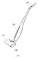
具体的には、図1〜図3を参照すると、該ベースは、折り畳みケース110、ベースケース120、サイドカバー130及びベースのリアケース140を含み、該折り畳みケース110は、ベースケース120の上方に取り付けられ、ベースケース120に対して回転して開くことができる。ベースのリアケース140は、ベースケース120の後下方に取り付けられ、サイドカバー130は、ベースケース120の両側にかけられる。
さらに図1〜図3を参照すると、ハンドルは、把持部と本体部を含む。該把持部は、把持部の上部ケース170と把持部のリアケース180を含み、本体部は、本体部の上部ケース150と本体部のリアケース160を含む。把持部が本体部に取り付けられ、本体部が接続機構500を介してベースと接続されることにより、ハンドルとベースとの接続が実現される。Specifically, referring to FIGS. 1 to 3, the base includes a
With further reference to FIGS. 1-3, the handle includes a grip and a body. The grip includes an
図3〜図6を参照すると、該掃除機構は、掃除コラムアセンブリ210と、掃除コラムにあるごみを清掃する清掃機構220と、掃除コラムアセンブリにあるごみを回収するごみ箱230とを含む。
掃除コラムアセンブリ210は、床面に直接接触して床面のごみを清掃し、可撓性材料で製造される掃除コラムを含み、本実施例において、スポンジコラム211を掃除コラムの例とする。Referring to FIGS. 3-6, the cleaning mechanism includes a
The
掃除コラムアセンブリ210は、さらに、スポンジコラム211を支持するスリーブ213と、スポンジコラム211及びスリーブ213の回転を駆動する掃除動力装置212とを含む。
掃除動力装置212は、ベースケース120の床面に垂直な方向の側壁に取り付けられ、ねじで締め付けることができる。スポンジコラム211のスリーブ213は、掃除動力装置212の外側に嵌着され、取り外して交換できる。スポンジコラム211はスリーブ213に嵌着され、掃除動力装置212はスリーブ213の中に取り付けられ、掃除動力装置212は、モータであり、制御部により掃除動力装置212のオンオフと回転方向などを制御する。The
The
図4を参照すると、該ごみ箱230は、スポンジコラム211の後下方に設置され、スポンジコラム211の回転に影響しない前提で、スポンジコラム211にできるだけ近接することにより、ごみがスポンジコラム211とごみ箱230との間の隙間から漏れることを回避する。
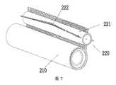
図7を参照すると、該清掃機構220は、回転体221と回転体221に設置された複数の清掃部材222とを含む。該回転体221は、清掃動力装置(清掃動力装置がモータあり、図示せず)によって駆動されて回転し、かつスポンジコラム211と同じ方向(時計回り又は逆時計回り)に回転する。該清掃部材222は、短冊状で、例えば、ブラッシ又は歯状物であり、回転体221と共に回転することができる。また、清掃部材222とスポンジコラム211は、ごみの体積よりも小さい隙間を有するか又は直接接触することにより、回転しながらスポンジコラム211にあるごみを清掃する。Referring to FIG. 4, the
Referring to FIG. 7, the
清掃機構220は、スポンジコラム211の後上方、即ちごみ箱230の上方に設置されて、スポンジコラム211から清掃されたごみをごみ箱230内に落下させる。
図7を参照すると、スポンジコラム211にあるごみをより効率的に清掃するために、清掃部材222は、少なくとも2組設置され、各組が複数の清掃部材222を含み、かつ回転体221の回転中心線に沿って配列され、配列の長さは、スポンジコラム211の回転中心線における長さより小さいか、大きいか又は等しい長さを選択することができる。The
Referring to FIG. 7, in order to clean the dust on the
また図7を参照すると、各組の清掃部材222の配列は、直線に沿って分布してもよく、また、各組の清掃部材222を波状に配列してもよいが、このような配列方式は、直線配列方式に比べて、清掃部材222がスポンジコラム211に与える抵抗を減少させ、エネルギー消費を減少させることができる。 Referring also to FIG. 7, the arrangement of cleaning
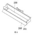
さらに、図4と図8を参照すると、掃除機構において、床面掃除機の掃除効果を向上させるために、スポンジコラム211の後方にスクレーパー240が設置され、該スクレーパー240は、例えばゴムで製造された柔軟な先端241を有し、該先端241が床面に密着されることにより、ごみが床面掃除機の下方から漏れることを回避する。図4と図10を参照すると、該スクレーパー240とスポンジコラム211との間に隙間が設置され、かつスクレーパー240のスポンジコラム211に向かっている外壁がスポンジコラム211に対応した円弧面に設計されることにより、該隙間は、ごみを入らせるようにガイドするガイドスロットとなる。 Further, referring to FIGS. 4 and 8, in the cleaning mechanism, a
図3、図4、図9、及び図11を参照すると、該給水機構は、洗浄チャンバー、清水タンク310、清水供給装置(本実施例では水ポンプ330)、汚水タンク320及び汚水回収装置(本実施例ではエアポンプ340)を含む。
洗浄チャンバーは、スポンジコラム211の回転軌跡に設置され、かつスポンジコラム211と密封的に組み合わせられ、洗浄チャンバー内に液体を収容して、スポンジコラム211を洗浄することができる。Referring to FIGS. 3, 4, 9 and 11, the water supply mechanism includes a washing chamber, a
The cleaning chamber is disposed on the rotational trajectory of the
本実施例において、図9、図10を参照すると、本実施例に係る洗浄チャンバーは水槽構造であり、その他の実施例においてその他の態様のチャンバーであってもよい。該水槽351は、ベースケース120(水槽ケースに相当)の一部が凹んだことで形成され、床面掃除機全体の構造を簡略化することができる。ただし、その他の実施例において、該水槽351は独立した水槽ケースで形成されてもよい。 In this embodiment, referring to FIGS. 9 and 10, the cleaning chamber according to this embodiment has a water tank structure, and in other embodiments, it may be a chamber of another aspect. The
該水槽351は、スポンジコラム211に反転してかけられ、水槽351のスポンジコラム211と接触する箇所は密封を維持する。密封を実現するために、本実施例の例示的構造では、水槽351の両側に密封部材352と絞り部材353がねじにより締め付けられ、密封部材352が絞り部材353の後方に位置し、即ち、スポンジコラム211は、まず密封部材352に移動し、次に絞り部材353に移動する。該絞り部材353と密封部材352は、それぞれ水槽351とスポンジコラム211の密封構造となり、また、絞り部材353はスポンジコラム211内の水分を絞り出す役割もはたす。スポンジコラム211から絞り出された汚水は水槽351内に直接的に入り、汚水タンク320により吸引される。 The
より高い絞り効果を達成するために、絞り部材353は硬質材料で製造され、そのスポンジコラム211の表面と接触する部分の外壁が円弧形であり、例えば硬質プラスチック、金属などで製造された押圧バー又は軸状物などである。密封部材352は密封効果のみをはたし、図11を参照すると、密封部材352のスポンジコラム211と接触する部分3521は、弾性材料で製造された突起状に設計され、その弾性は、スポンジコラム211内の汚水を水槽351の外に絞り出すことを回避することができる。
また、図9、図10を参照すると、スポンジコラム211にある大きなごみが給水機構に入って、流路を詰まることを回避するために、水槽351内に、さらに、両端が絞り部材353と密封部材352により水槽351内に圧着される濾過網354を設置してもよい。In order to achieve a higher throttling effect, the throttling
Further, referring to FIGS. 9 and 10, in order to prevent large debris in the
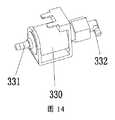
図3、図11、図12及び図14を参照すると、清水タンク310の清水流出口311、水槽351の清水流入口(図示せず)は、水ポンプ330と互いに連通し、該水ポンプ330の入水口331が清水流出口311と連通し、出水口332が清水流入口と連通し、水ポンプ330の作用下で清水が清水流入口から水槽351に入り、かつスポンジコラム211を洗浄した後に水槽351の汚水流出口1241から流出する。 Referring to FIGS. 3, 11, 12 and 14, the
また、図3、図11、図13、及び図15を参照すると、該汚水流出口1241、汚水タンク320の汚水流入口3211は、エアポンプ340と互いに連通する。具体的に、該エアポンプ340は汚水タンク320の抽気口3212と連通し、水槽351の汚水流出口1241は汚水タンク320の汚水流入口3211と連通する。該エアポンプ340は、汚水タンク320に対して抽気を行って、汚水タンク320内に負圧を生成することができ、該負圧により汚水タンク320は水槽351内から汚水を吸引することができる。エアポンプ340によって汚水を吸収する利点として、汚水タンク320の汚水吸引能力を容易に制御でき、実際の需要に応じて、柔軟に調節することができる。 Referring to FIGS. 3, 11, 13 and 15, the
当然のことながら、その他の実施例において、清水供給装置は、水ポンプ330に限定されず、その他の駆動装置である可能性もあり、例えば、該水ポンプ330のかわりにエアポンプを用いてもよく、該エアポンプは、水槽351と連通し、抽気して水槽351内の圧力を減少させることにより、清水タンク310から清水を吸引し、該原理は、上記汚水タンク320が汚水を回収する原理と類似している。
同様に、汚水回収装置は、エアポンプ340に限定されず、その他の駆動装置である可能性もあり、例えば、エアポンプ340のかわりに水ポンプを用いてもよく、該原理は、上記清水タンク310が清水を供給する原理と類似している。Of course, in other embodiments, the fresh water supply apparatus is not limited to the
Similarly, the sewage recovery apparatus is not limited to the
さらに、図3、図11、図13及び図15を参照すると、エアポンプ340の吸気口341が汚水タンク320と連通するので、エアポンプ340が吸気する場合、汚水タンク320が揺れれば、飛び散った水沫がエアポンプ340に吸引されやすい。
これに対して、汚水タンクのチャンバー内に少なくとも1つの水飛び防止部材が設置され、該少なくとも1つの水飛び防止部材が汚水タンクのチャンバーを分割して収容チャンバーを形成し、該収容チャンバーと抽気口が水飛び防止部材により隔てられ、該水飛び防止部材に収容チャンバーと抽気口とを連通させる通気口が開設され、通気口が抽気口と位置ずれして設置される。Furthermore, referring to FIG. 3, FIG. 11, FIG. 13 and FIG. 15, since the
On the other hand, at least one water splash preventing member is installed in the chamber of the dirty water tank, the at least one water splash preventing member divides the chamber of the dirty water tank to form a containing chamber, and the containing chamber and the bleed air A port is separated by a water splash preventing member, and a vent for communicating the storage chamber with the bleed port is opened in the water splash blocking member, and the air vent is disposed out of position with the bleed port.
本実施例の汚水タンク320への改良として、具体的に、汚水タンク320は、汚水を収容する収容チャンバーと少なくとも1つの水飛び防止部材とを有するように設計され、該水飛び防止部材が抽気口3212と収容チャンバーを隔て、水飛び防止部材に収容チャンバーと連通する通気口が開設され、汚水タンク320の抽気口3212が水飛び防止部材の通気口と連通することにより、飛び散った水沫の大部分は水飛び防止部材により遮断されるが、エアポンプ340の抽気に影響せず、水飛び防止部材の数が多ければ多いほど、その水飛び防止効果が高くなる。 As an improvement to the
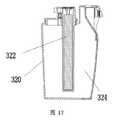
具体的に、図16、図17及び図18を参照すると、汚水タンク320は、汚水流入口3211及び抽気口3212が設置されたチャンバーと、液位検出装置322と、水飛び防止部材323とを含む。該液位検出装置322と水飛び防止部材323は、いずれもチャンバー内に取り付けられ、液位検出装置322は、汚水タンク320内の汚水の液量を検出し、制御部に接続され、一旦、汚水が最大値を超えると、スイッチがトリガーされて信号を制御部に送信する。 Specifically, referring to FIG. 16, FIG. 17 and FIG. 18, the
該水飛び防止部材323は、第1の緩衝貯蔵チャンバー3234を有し、その第1の緩衝貯蔵チャンバー3234にそれぞれ上下に設置された第1の通気口3231と第2の通気口3232が開設され、該第1の通気口3231と第2の通気口3232は異なる方向に設置され、第1の通気口3231が縦方向に沿って設置されるが、第2の通気口3232が収容チャンバー3235の流入口に向かって横方向に沿って設置される。このような位置ずれして設置されることは、第2の通気口3232から入った液体が第1の通気口3231に入ることを防止することができる。 The water
水飛び防止部材323がチャンバー内に取り付けられると、汚水タンク320のチャンバーを分割して1つの第2の緩衝貯蔵チャンバー3233と1つの収容チャンバー3235を形成し、収容チャンバー3235と第1の緩衝貯蔵チャンバー3234は第2の通気口3232を介して連通し、第2の緩衝貯蔵チャンバー3233と第1の緩衝貯蔵チャンバー3234は第1の通気口3231を介して連通し、抽気口3212は第2の緩衝貯蔵チャンバー3233と連通する。抽気口3212は横方向に沿って設置される。これにより、多重の水飛び防止により、エアポンプ340に吸引される水はほとんどない。
本願において、抽気口、第1の通気口及び第2の通気口のうちの少なくとも2つは、互いに位置ずれして設置される。上記互いに位置ずれして設置されることは、互いに異なる方向に位置する(例えば、抽気口3212と第1の通気口3231のうち、一方が横方向に沿って設置され、他方が縦方向に沿って設置される)場合、同じ方向での異なる位置に位置する(例えば、全部は縦方向に沿って設置されるが、互いに異なる直線に位置する)場合、及びその他の態様の位置ずれを含む。When the
In the present application, at least two of the bleed port, the first vent and the second vent are positioned out of alignment with one another. The above-mentioned mutually offset installation is located in different directions from each other (for example, one of the
また、汚水タンク320から飛び散った水沫がエアポンプ340に吸引されるという問題に対して、本実施例は、さらにその他の面で改良し、即ちエアポンプ340の排气口342とスポンジコラム211又は水槽351を連通させ、エアポンプ340の吸収した液体をスポンジコラム211又は水槽351に排出することができる。 In addition, the present embodiment is further improved in other respects to the problem of the water pump spouted from the
水槽351、清水タンク310、水ポンプ330、汚水タンク320及びエアポンプ340の間の流路チャンネルは、いずれも独立した管路で実現されてもよく、構造を簡略化するために、その他の部件と一体に設計してもよい。図3と図10を参照すると、ベースケース120の両側にそれぞれ清水槽、汚水槽124及び排水槽125が設置され、汚水槽124の一端が水槽351の汚水流出口1241であり、他端が汚水タンク320に接続された汚水伝送口1242であり、排水槽125の一端が排水流入口1251であり、他端が水槽351又はスポンジコラム211と連通する排水流出口1252である。清水槽は、ケースベース120の汚水槽124に対向している側に位置し、水ポンプ330と連通する接続口と水槽351の清水流入口とを含み、その構造は汚水槽124の構造とほぼ同じであるため、ここで、図面において詳細な説明をしていない。ベースケース120の両側のサイドカバー130がベースケース120にかけられると、該清水槽、汚水槽124及び排水槽125は、全部で密封された流路チャンネルを形成し、流路の連通を実現する。 The flow channel between the
さらに、清掃効果を向上させるために、スポンジコラム211を厚く製造する可能性があり、これで、スポンジを洗浄するときに、スポンジのより奥の部分にある水を絞り出すために、絞り部材353がスポンジコラム211に大きな力を与えることが必要になり、一旦、絞り力が大きすぎると、スポンジコラム211の回転を妨害し、スポンジコラム211の正常な回転を維持するために、エネルギーの入力を増大させることが必要になり、最終的に過大なエネルギー消費を招く。
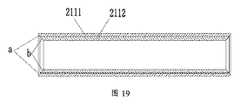
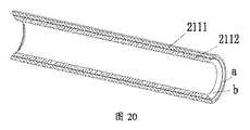
図19、図20を参照すると、本実施例は、スポンジコラム211を少なくとも2層、即ち外層に位置した吸水スポンジ層2111と内層の非吸水スポンジ層2112として設計し、該非吸水スポンジ層2112は非吸水性スポンジ材料で製造され、水分を吸収しない。吸水スポンジ層2111は、吸水性スポンジ材料で製造され、水分は主に外層の吸水スポンジ層2111に吸収されるので、水を絞る場合、外層の吸水スポンジ層2111にある水分を絞り出すだけでよく、外層の吸水スポンジの厚さが従来の全体的なスポンジ層より薄いので、大きな絞り力を必要とせずに水を絞ることができ、スポンジコラム211の回転を妨害することもない。Furthermore, in order to improve the cleaning effect, it is possible to make the
Referring to FIGS. 19 and 20, in this embodiment, the
さらに、一般的に、スポンジコラム211はベースケース120内に取り付けられ、従来の円柱形スポンジコラムの両端は床面に垂直な環状面であり、ベースケース120の左右の2つの側壁が一定の厚さを有し、該形状のため、スポンジコラム211は、ベースケース120の、スポンジコラム211と隣接している左右の側壁の下方まで延伸できず、それで、ベースケース120の、スポンジコラム211と隣接している左右の側壁の下方の領域が清掃のブラインドゾーンとなる。 Furthermore, generally, the
図5、図6、図19、及び図20を参照すると、本実施例に係るスポンジコラム211の両端は円錐面a、bであり、該円錐面a、bは、取り付けられると、ベースケース120の、スポンジコラム211と隣接している左右の側壁の床面に向かっている側の下方まで延伸でき、それにより該ブラインドゾーンの清掃を実現する。
該制御部は、制御回路が設置された回路基板とマンマシン・インタラクション・ユニットなどを含み、制御部が本願の改良の重点ではないため、ここで詳細な説明をしていない。図3にマンマシン・インタラクション・ユニットの1つとしての押しボタンのみを示す。Referring to FIGS. 5, 6, 19 and 20, both ends of the
The control unit includes a circuit board on which a control circuit is installed, a man-machine interaction unit, and the like, and the control unit is not the focus of the improvement of the present invention, so it is not described in detail here. FIG. 3 shows only the push button as one of the man-machine interaction units.
以上の内容は、具体的な実施形態と合わせて本発明をさらに詳細に説明したが、本発明の具体的な実施がこれらの説明に限定されるものではない。当業者にとって、本発明の構想から逸脱しない範囲で、複数の簡単な変形又は置き換えを行うことができる。 Although the foregoing has described the invention in further detail in conjunction with specific embodiments, specific implementations of the invention are not limited to these descriptions. Those skilled in the art can make several simple variations or replacements without departing from the concept of the present invention.
Claims (10)
Translated fromJapanese前記掃除コラムの表面に密封的にかけられた水槽と、
清潔な水源を貯蔵する清水タンクと、
前記清水タンクと前記水槽と互いに連通し、前記清水タンク内の清水を前記水槽内に流入させる清水供給装置と、
回収した汚水を貯蔵するチャンバーを有し、前記チャンバーに前記水槽と連通する汚水流入口と抽気口が開設される汚水タンクと、
吸気口が前記抽気口と連通し、排気口が前記掃除コラムの表面又は前記水槽と連通するエアポンプと、
を含むことを特徴とする床面掃除機。A cleaning column that cleans the floor,
And a water tank that has been subjected to sealingly on the surface ofthe cleaning column,
Fresh water tank which stores clean water source,
Communicate with each other and the fresh water tank andthe water tank, a fresh water supply device for flowing fresh water ofthe fresh water tank intothe water tank,
Has a chamber for storing the collected sewage, the sewage tank sewage inlet and extraction port tothe water tank and communicating with the chamber is opened,
And an air pump inlet issaidto extraction port and communicatingthe exhaust port communicates with the surface or the aquarium of the cleaning column,
A floor vacuum cleaner characterized by including.
前記水飛び防止部材に前記収容チャンバーと前記抽気口とを連通させる通気口が開設され、前記通気口が前記抽気口と互いに位置ずれして設置されることを特徴とする請求項1に記載の床面掃除機。At least one water skip preventing member is disposed within said chamber, separated by the at least one water skip preventing member forms a housing chamber dividingthe chamber, preventing member the accommodation chamber andthe extraction port is splashing And
Wherein the water jumpthe accommodating chamber prevention member extraction port and vent for communicating is opened, the vent according to claim 1, characterized in that it is placed at a position displacedfrom each other andthe extraction port Floor vacuum cleaner.
前記水飛び防止部材が前記チャンバー内に取り付けられると、前記チャンバーを分割して第2の緩衝貯蔵チャンバーと収容チャンバーを形成し、
前記収容チャンバーが前記第2の通気口を介して前記第1の緩衝貯蔵チャンバーと連通し、前記第2の緩衝貯蔵チャンバーが前記第1の通気口を介して前記第1の緩衝貯蔵チャンバーと連通し、前記抽気口が前記第2の緩衝貯蔵チャンバーと連通し、
前記抽気口、前記第1の通気口及び前記第2の通気口のうちの少なくとも2つが互いに位置ずれして設置されることを特徴とする請求項1に記載の床面掃除機。A splash prevention member is installed in the chamber, the splash prevention member has a first buffer storage chamber, and the first buffer storage chamber is provided with first vents installed vertically and the first buffer storage chamber. Two vents are opened,
When the water skip preventing member is attached tothe chamber to form a second buffer reservoir chamber and the housing chamber dividing the chamber,
The receiving chamber communicating withsaid first buffer storage chamber viasaid second vent,said first buffer storage chamber communicating with said second buffer storage chamber throughsaid first vent and, wherein the bleed port communicating withsaid second buffer storage chamber,
The bleed ports, floor cleaner according to claim1, wherein the first at least two of the vent andthe second vent, characterized in that it is placed at a position displaced from each other.
Applications Claiming Priority (1)
| Application Number | Priority Date | Filing Date | Title |
|---|---|---|---|
| PCT/CN2015/091682WO2017059600A1 (en) | 2015-10-10 | 2015-10-10 | Floor cleaner |
Related Child Applications (1)
| Application Number | Title | Priority Date | Filing Date |
|---|---|---|---|
| JP2019082833ADivisionJP2019115789A (en) | 2019-04-24 | 2019-04-24 | Floor cleaner |
Publications (2)
| Publication Number | Publication Date |
|---|---|
| JP2018511476A JP2018511476A (en) | 2018-04-26 |
| JP6525222B2true JP6525222B2 (en) | 2019-06-05 |
Family
ID=58487216
Family Applications (1)
| Application Number | Title | Priority Date | Filing Date |
|---|---|---|---|
| JP2017563375AActiveJP6525222B2 (en) | 2015-10-10 | 2015-10-10 | Floor vacuum cleaner |
Country Status (10)
| Country | Link |
|---|---|
| US (2) | US10039431B1 (en) |
| EP (2) | EP3520666B1 (en) |
| JP (1) | JP6525222B2 (en) |
| KR (1) | KR102072512B1 (en) |
| CN (1) | CN108348123A (en) |
| ES (1) | ES2736100T3 (en) |
| HU (1) | HUE044586T2 (en) |
| PL (2) | PL3238595T3 (en) |
| PT (1) | PT3238595T (en) |
| WO (1) | WO2017059600A1 (en) |
Families Citing this family (43)
| Publication number | Priority date | Publication date | Assignee | Title |
|---|---|---|---|---|
| CN107007213B (en)* | 2017-05-19 | 2022-06-07 | 深圳不惑科技有限公司 | A self-cleaning drum mop |
| US10575701B2 (en) | 2017-09-15 | 2020-03-03 | Omachron Intellectual Property Inc. | Surface cleaning apparatus |
| USD897059S1 (en)* | 2017-10-20 | 2020-09-22 | Shenzhen Hizero Technologies Co., Ltd. | Floor cleaner |
| WO2019157662A1 (en)* | 2018-02-13 | 2019-08-22 | 深圳市赫兹科技有限公司 | Robotic vacuum cleaner and drum-based cleaning device thereof |
| CN110785638A (en) | 2018-02-13 | 2020-02-11 | 深圳市赫兹科技有限公司 | Sewage collection and testing mechanism and cleaning device |
| EP3524121A1 (en)* | 2018-02-13 | 2019-08-14 | HiZero Technologies Co., Ltd | Sewage collection and detection mechanism and cleaning device |
| GB2570972B (en) | 2018-02-13 | 2020-07-01 | Hizero Tech Co Ltd | A ground cleaning device |
| WO2019157646A1 (en)* | 2018-02-13 | 2019-08-22 | 深圳市赫兹科技有限公司 | Robotic vacuum cleaner and two-purpose water tank thereof |
| CN110868900A (en)* | 2018-02-13 | 2020-03-06 | 深圳市赫兹科技有限公司 | Sweeping robot and cleaning mechanism thereof |
| AU2019331419B2 (en) | 2018-08-27 | 2022-08-04 | Techtronic Floor Care Technology Limited | Floor cleaner |
| AU2020100432A4 (en) | 2019-03-28 | 2020-04-23 | Bissell Inc. | Surface cleaning apparatus with two-stage collection |
| EP3952712A1 (en) | 2019-04-12 | 2022-02-16 | Alfred Kärcher SE & Co. KG | Surface cleaning machine having a boost mode, and method for operating a surface cleaning machine |
| CN211633137U (en)* | 2019-11-28 | 2020-10-09 | 深圳不惑科技有限公司 | Self-cleaning type roller cleaning equipment |
| CN113796790B (en) | 2020-06-12 | 2022-05-24 | 苏州爱普电器有限公司 | Surface cleaning machine |
| USD988624S1 (en)* | 2020-12-29 | 2023-06-06 | Wuhan Dishui Intelligent Technology Co., Ltd. | Hand-held scrubber |
| CN112998598A (en)* | 2021-03-27 | 2021-06-22 | 深圳市杰深科技有限公司 | Cleaning device |
| USD1035194S1 (en)* | 2021-06-04 | 2024-07-09 | Sharkninja Operating Llc | Vacuum cleaner |
| CN114617496B (en)* | 2021-07-20 | 2023-08-04 | 尚科宁家(中国)科技有限公司 | Low-noise surface cleaning machine |
| CN113647869B (en)* | 2021-08-23 | 2023-08-11 | 北京小狗吸尘器集团股份有限公司 | Hanging plate assembly and floor washing machine |
| DE102021134552A1 (en) | 2021-12-23 | 2023-06-29 | Alfred Kärcher SE & Co. KG | Articulated floor cleaning machine and method of operating a floor cleaning machine |
| DE102021134577A1 (en) | 2021-12-23 | 2023-06-29 | Alfred Kärcher SE & Co. KG | Floor cleaning machine with kick tab and method for removing a dirt fluid tank assembly from a cleaning head |
| DE102021134463A1 (en) | 2021-12-23 | 2023-07-13 | Alfred Kärcher SE & Co. KG | Surface cleaning machine with curved scraper element |
| DE102021134612A1 (en) | 2021-12-23 | 2023-06-29 | Alfred Kärcher SE & Co. KG | Floor cleaning machine with at least one supporting element |
| CN114587215A (en)* | 2021-12-31 | 2022-06-07 | 北京石头世纪科技股份有限公司 | Automatically cleaning collection dirt seat and dust collecting system |
| WO2023151833A1 (en) | 2022-02-08 | 2023-08-17 | Alfred Kärcher SE & Co. KG | Floor cleaning device with a sweeping device and method for operating a floor cleaning device |
| DE102022102937A1 (en) | 2022-02-08 | 2023-08-10 | Alfred Kärcher SE & Co. KG | Floor cleaning device with dirt fluid tank |
| WO2023152163A1 (en) | 2022-02-08 | 2023-08-17 | Alfred Kärcher SE & Co. KG | Floor cleaning device with a pivot bearing unit with an abutment |
| DE202022101314U1 (en) | 2022-02-08 | 2022-06-20 | Alfred Kärcher SE & Co. KG | Floor cleaning device with dirt fluid tank |
| DE202022101312U1 (en) | 2022-02-08 | 2022-06-20 | Alfred Kärcher SE & Co. KG | Floor cleaning device with cassette |
| DE202022101313U1 (en) | 2022-02-08 | 2022-06-20 | Alfred Kärcher SE & Co. KG | Floor cleaning device with movable scraper element |
| DE102022133009A1 (en) | 2022-02-08 | 2023-08-10 | Alfred Kärcher SE & Co. KG | Floor cleaning device with pivot bearing device with counter bearing |
| DE102022102918A1 (en) | 2022-02-08 | 2023-08-10 | Alfred Kärcher SE & Co. KG | Floor cleaning device with cassette |
| DE102022102924A1 (en) | 2022-02-08 | 2023-08-10 | Alfred Kärcher SE & Co. KG | Floor cleaning device with movable scraper element |
| CN114468900B (en)* | 2022-03-08 | 2025-02-07 | 湖北穿石智能电器有限公司 | A water tank cover, water tank and cleaning tool for mopping and sweeping |
| DE102022124120A1 (en) | 2022-09-20 | 2024-03-21 | Alfred Kärcher SE & Co. KG | Floor cleaning device with a basin and method for operating a floor cleaning device |
| DE102022133006A1 (en) | 2022-12-12 | 2024-06-13 | Alfred Kärcher SE & Co. KG | Floor cleaning device with dirt fluid tank with two areas |
| DE102022133004A1 (en) | 2022-12-12 | 2024-06-13 | Alfred Kärcher SE & Co. KG | Floor cleaning device with floor head with wall |
| AU2023424754A1 (en) | 2023-01-20 | 2025-07-31 | Sharkninja Operating Llc | Extraction cleaner |
| WO2024170089A1 (en) | 2023-02-16 | 2024-08-22 | Alfred Kärcher SE & Co. KG | Floor cleaning machine with base module and cleaning module |
| DE102023104615A1 (en) | 2023-02-24 | 2024-08-29 | Alfred Kärcher SE & Co. KG | Surface cleaning machine with hot fluid generating device and method for operating a surface cleaning machine |
| CN116327056A (en)* | 2023-04-20 | 2023-06-27 | 云鲸智能(深圳)有限公司 | Control method of cleaning device, cleaning device and computer readable storage medium |
| CN223350132U (en) | 2023-05-23 | 2025-09-19 | 尚科宁家运营有限公司 | Surface cleaning device and surface cleaning head |
| CN119112056A (en)* | 2023-06-06 | 2024-12-13 | 追觅创新科技(苏州)有限公司 | Liquid supply mechanism, surface cleaning device and liquid supply method |
Family Cites Families (43)
| Publication number | Priority date | Publication date | Assignee | Title |
|---|---|---|---|---|
| FR651101A (en) | 1927-03-29 | 1929-02-14 | Electrically operated scrubber | |
| US2881461A (en) | 1956-10-29 | 1959-04-14 | Wynton E Parker | Paint roller for curved surfaces |
| US3172138A (en) | 1963-09-16 | 1965-03-09 | William B Price | Surface treating apparatus |
| JPS5029975B2 (en) | 1972-04-24 | 1975-09-27 | ||
| US4959628A (en)* | 1988-07-22 | 1990-09-25 | Quad Research, Inc. | Rotating electric switch actuated by fixed magnetic means, usable for a surface cleaning device |
| JPH078418A (en)* | 1991-08-30 | 1995-01-13 | Tatsuo Okabe | Attachment for suction/collection vessel |
| JPH0731569A (en)* | 1993-07-20 | 1995-02-03 | Fujitsu General Ltd | Floor cleaner |
| CN2241510Y (en) | 1995-05-31 | 1996-12-04 | 谢嘉益 | A kind of swab |
| JP3497425B2 (en)* | 1999-09-30 | 2004-02-16 | アマノ株式会社 | Steam-water separator for floor washer |
| DE10001467B4 (en) | 2000-01-15 | 2004-04-08 | Düpro AG | vacuum cleaning tool |
| TW558430B (en) | 2000-11-01 | 2003-10-21 | Kao Corp | Cleaning device |
| JP2004147669A (en) | 2002-10-28 | 2004-05-27 | Toshiba Tec Corp | Suction port body and vacuum cleaner |
| US7279050B2 (en) | 2002-10-29 | 2007-10-09 | Xerox Corporation | One-piece bottom edge wipe sponge for cleaning a photoreceptor drum |
| AU2004202941B2 (en)* | 2004-03-09 | 2006-02-02 | Lg Electronics Inc | Complex type cleaner |
| US8079112B2 (en) | 2004-11-17 | 2011-12-20 | Butler Home Products, Llc | Disposable liquid absorbing cleaning pad for a hand held cleaning implement having an elongated handle |
| CN2794412Y (en)* | 2005-04-09 | 2006-07-12 | 袁仁华 | Wet type drum vacuum cleaner |
| CN100370941C (en)* | 2006-04-21 | 2008-02-27 | 泰怡凯电器(苏州)有限公司 | water filtration device |
| BRPI0720239B1 (en) | 2006-12-13 | 2018-09-25 | Electrolux Ab | dry floor cleaning device / wet |
| DE102007029258A1 (en)* | 2007-06-15 | 2008-12-18 | Alfred Kärcher Gmbh & Co. Kg | Floor cleaning device |
| WO2009018688A1 (en) | 2007-08-06 | 2009-02-12 | Ann Vee Ltd | Surface debris removal apparatus |
| DE102007052982A1 (en) | 2007-11-07 | 2009-05-14 | Vorwerk & Co. Interholding Gmbh | Cleaning device i.e. suction cleaning device, for use in handle-guided household-vacuum cleaner for floor cleaning i.e. wet floor cleaning, has cleaning cover fixedly attached to hollow body, and liquid barrier provided below cover |
| CN201533808U (en)* | 2009-06-21 | 2010-07-28 | 艾和金 | Sewage suction device |
| JP5589092B2 (en)* | 2010-01-08 | 2014-09-10 | ダイソン テクノロジー リミテッド | Vacuum cleaner head |
| KR101573742B1 (en) | 2010-10-25 | 2015-12-07 | 삼성전자주식회사 | Autonomous cleaning device |
| JP5230775B2 (en) | 2011-06-09 | 2013-07-10 | 惠司 細川 | Condensation remover |
| CN102293607A (en)* | 2011-09-06 | 2011-12-28 | 杜爵伟 | Automatic floor cleaning machine |
| AU2013205936B2 (en)* | 2012-05-29 | 2017-06-29 | Bissell Inc. | Extraction cleaner |
| EP2876937B1 (en) | 2012-07-20 | 2020-05-06 | Sony Corporation | Wireless communication apparatus, information processing apparatus, communication system, communication quality calculating method and program |
| JP5988849B2 (en)* | 2012-11-30 | 2016-09-07 | 株式会社マキタ | Dust collector |
| KR101452617B1 (en)* | 2013-03-08 | 2014-10-22 | 박미경 | Vacuum cleaner with damp roller |
| US9682399B2 (en) | 2013-03-15 | 2017-06-20 | Affordable Countertop Solutions, Inc. | Paint roller |
| TWM469037U (en) | 2013-05-07 | 2014-01-01 | qing-ji Lin | Electric sweep/wash device |
| CN203263303U (en)* | 2013-05-23 | 2013-11-06 | 林清吉 | Electric sweeping and washing device |
| JP5731575B2 (en)* | 2013-06-04 | 2015-06-10 | 登 井上 | Cleaning machine |
| CN203506629U (en) | 2013-06-20 | 2014-04-02 | 苏州经贸职业技术学院 | Multifunctional cleaner |
| JP3186168U (en)* | 2013-07-10 | 2013-09-19 | 清吉 林 | Electric cleaning and cleaning device |
| US9414733B2 (en)* | 2013-07-16 | 2016-08-16 | Techtronic Industries Co. Ltd. | Floor cleaning machine |
| CN203428324U (en) | 2013-09-06 | 2014-02-12 | 徐州万邦道路工程装备服务股份公司 | Sensing garbage can device |
| US20150082579A1 (en) | 2013-09-26 | 2015-03-26 | Ching-Chi Lin | Electric sweeping washing device |
| CN204105933U (en) | 2014-09-24 | 2015-01-21 | 周嘉顺 | Microscopy endoscopic mirror system under the balloon expandable device of a kind of synovium of joint chamber |
| US9713411B2 (en) | 2014-10-20 | 2017-07-25 | The Kirby Company / Scott Fetzer Company | Surface-treatment apparatus and head unit |
| CN204520539U (en)* | 2015-01-29 | 2015-08-05 | 梁胜昔 | Robot for cleaning floor and water circulation system thereof |
| CN205181250U (en)* | 2015-10-12 | 2016-04-27 | 深圳市赫兹科技有限公司 | Floor cleaner |
- 2015
- 2015-10-10WOPCT/CN2015/091682patent/WO2017059600A1/ennot_activeCeased
- 2015-10-10CNCN201580083989.XApatent/CN108348123A/enactivePending
- 2015-10-10USUS15/122,436patent/US10039431B1/enactiveActive
- 2015-10-10EPEP19166094.3Apatent/EP3520666B1/enactiveActive
- 2015-10-10PLPL15905698Tpatent/PL3238595T3/enunknown
- 2015-10-10PLPL19166094.3Tpatent/PL3520666T3/enunknown
- 2015-10-10EPEP15905698.5Apatent/EP3238595B1/enactiveActive
- 2015-10-10ESES15905698Tpatent/ES2736100T3/enactiveActive
- 2015-10-10HUHUE15905698patent/HUE044586T2/enunknown
- 2015-10-10PTPT15905698Tpatent/PT3238595T/enunknown
- 2015-10-10JPJP2017563375Apatent/JP6525222B2/enactiveActive
- 2015-10-10KRKR1020187013361Apatent/KR102072512B1/enactiveActive
- 2018
- 2018-08-06USUS16/055,486patent/US10729303B2/enactiveActive
Also Published As
| Publication number | Publication date |
|---|---|
| EP3520666A1 (en) | 2019-08-07 |
| US10729303B2 (en) | 2020-08-04 |
| PL3238595T3 (en) | 2019-12-31 |
| EP3238595A4 (en) | 2018-09-05 |
| EP3238595B1 (en) | 2019-05-08 |
| KR20180099632A (en) | 2018-09-05 |
| WO2017059600A1 (en) | 2017-04-13 |
| PL3520666T3 (en) | 2023-01-09 |
| US10039431B1 (en) | 2018-08-07 |
| HUE044586T2 (en) | 2019-11-28 |
| US20180338660A1 (en) | 2018-11-29 |
| CN108348123A (en) | 2018-07-31 |
| PT3238595T (en) | 2019-08-02 |
| KR102072512B1 (en) | 2020-02-03 |
| EP3238595A1 (en) | 2017-11-01 |
| EP3520666B1 (en) | 2022-08-17 |
| US20180206689A1 (en) | 2018-07-26 |
| JP2018511476A (en) | 2018-04-26 |
| ES2736100T3 (en) | 2019-12-26 |
Similar Documents
| Publication | Publication Date | Title |
|---|---|---|
| JP6525222B2 (en) | Floor vacuum cleaner | |
| JP6516391B2 (en) | Floor vacuum cleaner and its water tank structure | |
| JP2019115789A (en) | Floor cleaner | |
| JP6708820B2 (en) | Floor cleaner and its cleaning column cleaning mechanism | |
| JP2019107563A (en) | Floor cleaner and water tank structure thereof | |
| JP2018506413A (en) | Floor cleaner, cleaning column assembly and sponge column |
Legal Events
| Date | Code | Title | Description |
|---|---|---|---|
| A977 | Report on retrieval | Free format text:JAPANESE INTERMEDIATE CODE: A971007 Effective date:20180724 | |
| A131 | Notification of reasons for refusal | Free format text:JAPANESE INTERMEDIATE CODE: A131 Effective date:20180731 | |
| A521 | Request for written amendment filed | Free format text:JAPANESE INTERMEDIATE CODE: A523 Effective date:20181017 | |
| RD02 | Notification of acceptance of power of attorney | Free format text:JAPANESE INTERMEDIATE CODE: A7422 Effective date:20181017 | |
| A521 | Request for written amendment filed | Free format text:JAPANESE INTERMEDIATE CODE: A523 Effective date:20181127 | |
| RD04 | Notification of resignation of power of attorney | Free format text:JAPANESE INTERMEDIATE CODE: A7424 Effective date:20181109 | |
| TRDD | Decision of grant or rejection written | ||
| A01 | Written decision to grant a patent or to grant a registration (utility model) | Free format text:JAPANESE INTERMEDIATE CODE: A01 Effective date:20190405 | |
| RD02 | Notification of acceptance of power of attorney | Free format text:JAPANESE INTERMEDIATE CODE: A7422 Effective date:20190411 | |
| A61 | First payment of annual fees (during grant procedure) | Free format text:JAPANESE INTERMEDIATE CODE: A61 Effective date:20190424 | |
| R150 | Certificate of patent or registration of utility model | Ref document number:6525222 Country of ref document:JP Free format text:JAPANESE INTERMEDIATE CODE: R150 | |
| S111 | Request for change of ownership or part of ownership | Free format text:JAPANESE INTERMEDIATE CODE: R313113 | |
| S531 | Written request for registration of change of domicile | Free format text:JAPANESE INTERMEDIATE CODE: R313531 | |
| R360 | Written notification for declining of transfer of rights | Free format text:JAPANESE INTERMEDIATE CODE: R360 | |
| R360 | Written notification for declining of transfer of rights | Free format text:JAPANESE INTERMEDIATE CODE: R360 | |
| R371 | Transfer withdrawn | Free format text:JAPANESE INTERMEDIATE CODE: R371 | |
| R350 | Written notification of registration of transfer | Free format text:JAPANESE INTERMEDIATE CODE: R350 | |
| S111 | Request for change of ownership or part of ownership | Free format text:JAPANESE INTERMEDIATE CODE: R313113 | |
| R350 | Written notification of registration of transfer | Free format text:JAPANESE INTERMEDIATE CODE: R350 | |
| R250 | Receipt of annual fees | Free format text:JAPANESE INTERMEDIATE CODE: R250 | |
| R250 | Receipt of annual fees | Free format text:JAPANESE INTERMEDIATE CODE: R250 | |
| R250 | Receipt of annual fees | Free format text:JAPANESE INTERMEDIATE CODE: R250 | |
| R250 | Receipt of annual fees | Free format text:JAPANESE INTERMEDIATE CODE: R250 |