JP6523326B2 - In-Situ Estimation of Sound Level by Non-fundamental Analysis - Google Patents
In-Situ Estimation of Sound Level by Non-fundamental AnalysisDownload PDFInfo
- Publication number
- JP6523326B2 JP6523326B2JP2016561335AJP2016561335AJP6523326B2JP 6523326 B2JP6523326 B2JP 6523326B2JP 2016561335 AJP2016561335 AJP 2016561335AJP 2016561335 AJP2016561335 AJP 2016561335AJP 6523326 B2JP6523326 B2JP 6523326B2
- Authority
- JP
- Japan
- Prior art keywords
- measurement
- response
- calibration
- function
- power level
- Prior art date
- Legal status (The legal status is an assumption and is not a legal conclusion. Google has not performed a legal analysis and makes no representation as to the accuracy of the status listed.)
- Active
Links
Images


Classifications
- A—HUMAN NECESSITIES
- A61—MEDICAL OR VETERINARY SCIENCE; HYGIENE
- A61B—DIAGNOSIS; SURGERY; IDENTIFICATION
- A61B8/00—Diagnosis using ultrasonic, sonic or infrasonic waves
- A61B8/48—Diagnostic techniques
- A61B8/481—Diagnostic techniques involving the use of contrast agents, e.g. microbubbles introduced into the bloodstream
- A—HUMAN NECESSITIES
- A61—MEDICAL OR VETERINARY SCIENCE; HYGIENE
- A61B—DIAGNOSIS; SURGERY; IDENTIFICATION
- A61B8/00—Diagnosis using ultrasonic, sonic or infrasonic waves
- A61B8/06—Measuring blood flow
- A—HUMAN NECESSITIES
- A61—MEDICAL OR VETERINARY SCIENCE; HYGIENE
- A61B—DIAGNOSIS; SURGERY; IDENTIFICATION
- A61B8/00—Diagnosis using ultrasonic, sonic or infrasonic waves
- A61B8/52—Devices using data or image processing specially adapted for diagnosis using ultrasonic, sonic or infrasonic waves
- A61B8/5269—Devices using data or image processing specially adapted for diagnosis using ultrasonic, sonic or infrasonic waves involving detection or reduction of artifacts
- A—HUMAN NECESSITIES
- A61—MEDICAL OR VETERINARY SCIENCE; HYGIENE
- A61B—DIAGNOSIS; SURGERY; IDENTIFICATION
- A61B8/00—Diagnosis using ultrasonic, sonic or infrasonic waves
- A61B8/58—Testing, adjusting or calibrating the diagnostic device
- A—HUMAN NECESSITIES
- A61—MEDICAL OR VETERINARY SCIENCE; HYGIENE
- A61N—ELECTROTHERAPY; MAGNETOTHERAPY; RADIATION THERAPY; ULTRASOUND THERAPY
- A61N7/00—Ultrasound therapy
- A61N7/02—Localised ultrasound hyperthermia
- A—HUMAN NECESSITIES
- A61—MEDICAL OR VETERINARY SCIENCE; HYGIENE
- A61N—ELECTROTHERAPY; MAGNETOTHERAPY; RADIATION THERAPY; ULTRASOUND THERAPY
- A61N7/00—Ultrasound therapy
- A61N2007/0039—Ultrasound therapy using microbubbles
- A—HUMAN NECESSITIES
- A61—MEDICAL OR VETERINARY SCIENCE; HYGIENE
- A61N—ELECTROTHERAPY; MAGNETOTHERAPY; RADIATION THERAPY; ULTRASOUND THERAPY
- A61N7/00—Ultrasound therapy
- A61N2007/0052—Ultrasound therapy using the same transducer for therapy and imaging
Landscapes
- Health & Medical Sciences (AREA)
- Life Sciences & Earth Sciences (AREA)
- Engineering & Computer Science (AREA)
- Biomedical Technology (AREA)
- Nuclear Medicine, Radiotherapy & Molecular Imaging (AREA)
- Radiology & Medical Imaging (AREA)
- Animal Behavior & Ethology (AREA)
- General Health & Medical Sciences (AREA)
- Public Health (AREA)
- Veterinary Medicine (AREA)
- Medical Informatics (AREA)
- Physics & Mathematics (AREA)
- Biophysics (AREA)
- Pathology (AREA)
- Heart & Thoracic Surgery (AREA)
- Molecular Biology (AREA)
- Surgery (AREA)
- Hematology (AREA)
- Computer Vision & Pattern Recognition (AREA)
- Ultra Sonic Daignosis Equipment (AREA)
Description
Translated fromJapanese本開示によるソリューションは、医学的応用の分野に関する。より詳細には、本ソリューションは、超音波スキャナの使用に関する。 The solution according to the present disclosure relates to the field of medical applications. More particularly, the solution relates to the use of an ultrasound scanner.
超音波スキャナは、いくつかの医療適用において日常的に使用されている。一般的な例は、診断適用におけるものである。この事例において、分析されるべき患者の身体部分に超音波が印加され、それに応答して記録される、対応するエコー信号が、(その身体部分の形態学的表現を与える)解剖学的画像または(身体部分の特性パラメータの空間分布を与える)パラメトリック画像を作成するために使用され得る。最近では、超音波スキャナは、治療適用にも導入されるようになってきている。この事例において、超音波は、身体部分に対する生物学的効果を意図的に誘発するように、身体部分に印加され、特に、可逆的細胞効果(たとえば、音響(微小)流による)または細胞死(たとえば、(慣性)音響キャビテーションの間接的効果による)を得ることが可能である。これらの治療適用の一般的な例は、ソノポレーション、超音波血栓溶解および高密度焦点式超音波(HIFU)治療である。 Ultrasound scanners are routinely used in several medical applications. A common example is in diagnostic applications. In this case, ultrasound waves are applied to the body part of the patient to be analyzed and the corresponding echo signals recorded in response are anatomical images (providing a morphological representation of the body part) or It can be used to create parametric images (providing spatial distribution of characteristic parameters of body parts). Recently, ultrasound scanners have also been introduced for therapeutic applications. In this case, ultrasound is applied to the body part so as to deliberately induce a biological effect on the body part, in particular a reversible cell effect (for example by acoustic (micro) flow) or cell death ( For example, it is possible to obtain the indirect effect of (inertial) acoustic cavitation). Common examples of these therapeutic applications are sonoporation, ultrasound thrombolysis and high intensity focused ultrasound (HIFU) treatment.
超音波スキャナはまた、たとえば、リン脂質安定化気体充填微小気泡の懸濁液から作成される(超音波)造影剤(UCA)を使用することも含み得る。特に、診断適用において、この造影剤の粒子(たとえば、微小気泡)の反射特性が、その追跡を(たとえば、造影剤は、患者内の赤血球と同じ速度で流れるため、血液灌流情報を得ることを)容易にする。その上、治療適用では、造影剤粒子は、微小流促進剤またはキャビテーション核として作用し得る。 The ultrasound scanner may also include, for example, using (ultrasound) contrast agents (UCA) made from a suspension of phospholipid stabilized gas filled microbubbles. In particular, in diagnostic applications, the reflective properties of this contrast agent particle (e.g. microbubbles) cause its tracking (e.g. contrast agent flows at the same rate as red blood cells in the patient, so that blood perfusion information is obtained )make it easier. Moreover, in therapeutic applications, contrast agent particles can act as microflow promoters or cavitation nuclei.
超音波によって造影剤粒子に印加される音圧のレベルは、種々の医療適用に従って大きく変化する。たとえば、診断適用において、音圧は、熱的または非熱的機構によって誘発され得る身体部分のいかなる望ましくない生物学的効果も回避するために、相対的に低くあるべきである。逆に治療適用において、所望の効果を達成するために、相対的に高い音圧が必要とされる。たとえば、造影剤粒子が安定して可逆的に振動するときには音響流が存在することが知られており、一方で、音響キャビテーションの条件においては、造影剤粒子はより激しく振動し、最終的にはそれらの粒子が破壊されることになる。 The level of sound pressure applied to the contrast agent particles by ultrasound varies widely according to various medical applications. For example, in diagnostic applications, sound pressure should be relatively low to avoid any undesirable biological effects of body parts that may be induced by thermal or non-thermal mechanisms. Conversely, in therapeutic applications, relatively high sound pressure is required to achieve the desired effect. For example, it is known that an acoustic flow is present when the contrast agent particles are stably and reversibly vibrated, while in acoustic cavitation conditions the contrast agent particles vibrate more violently and eventually Those particles will be destroyed.
造影剤に対して実際にその場(in−situ)で印加される音圧の決定は、インビトロ(in−vitro)条件(音圧を直接的に測定することができる)においては相対的に単純である。しかしながら、インビボ(in−vivo)条件において、これは非常に困難(またはさらには不可能)である。事実、この事例において、音圧は、身体部分内で測定することはできず、超音波スキャナによって印加される超音波の音圧から推定することしかできない。しかしながら、超音波スキャナのトランスデューサと身体部分との間に介在する患者の解剖学的構造は、超音波の伝搬と強く干渉する。結果として、超音波は減衰を受け、解剖学的構造を通じて伝播する間に、それらの音圧、したがってエネルギーが、漸進的に低減する。超音波の減衰の主な原因は、(超音波のわずかな反射/散乱に加えて)、解剖学的構造による超音波の吸収であり、超音波のエネルギーが熱に変換されてしまう(その後、失われる)。その上、造影剤の存在も、超音波の減衰に劇的に影響し得る。特に(超音波のエネルギーが造影剤の濃度に従って線形的に減衰することに加えて)、造影剤は、超音波の減衰がそれらのエネルギーおよび周波数に強く依存することを含む、非線形的な特性を有する。 The determination of the sound pressure actually applied in-situ to the contrast agent is relatively simple in in-vitro conditions (sound pressure can be measured directly). It is. However, in in-vivo conditions this is very difficult (or even impossible). In fact, in this case, the sound pressure can not be measured in the body part but can only be estimated from the sound pressure of the ultrasound applied by the ultrasound scanner. However, the patient's anatomy interposed between the transducer of the ultrasound scanner and the body part strongly interferes with the ultrasound propagation. As a result, the ultrasound waves are attenuated and their sound pressure, and hence energy, progressively decrease while propagating through the anatomical structure. The main cause of ultrasound attenuation (in addition to slight reflection / scattering of ultrasound) is the absorption of ultrasound by anatomical structures, and the energy of ultrasound is converted to heat (then Lost). Moreover, the presence of contrast agents can also dramatically affect ultrasound attenuation. In particular (in addition to the fact that the energy of the ultrasound decays linearly according to the concentration of the contrast agent), the contrast agents have non-linear characteristics, including that the attenuation of the ultrasound is strongly dependent on their energy and frequency. Have.
結果として、造影剤粒子またはそれらの周囲に対して実際にin−situで印加される音圧を正確に制御することは可能でない。これは、超音波スキャナのいくつかの医療適用が実践されることを妨げるおそれがある。特に、音圧を制御することが困難であることは、いくつかの治療適用にとって(たとえば、超音波血栓溶解のように、造影剤粒子の安定した可逆的な振動が必要とされるときに)有害であり、事実、造影剤粒子に印加される音圧がそれらの振動を決定付けるため、音圧が正確に分かっていないことによって、(低すぎるときに)治療適用の効率が低減する場合があり、または、(高すぎるときに)超音波に過剰に晒されることに起因して望ましくない副次的影響が引き起こされる場合がある。 As a result, it is not possible to precisely control the sound pressure that is actually applied in-situ to the contrast agent particles or their surroundings. This can prevent some medical applications of ultrasound scanners from being practiced. In particular, it is difficult to control sound pressure for some therapeutic applications (e.g. when stable, reversible oscillation of contrast agent particles is required, as in ultrasonic thrombolysis) Harmful, in fact, because the sound pressure applied to the contrast agent particles determines their vibration, the efficiency of the treatment application may be reduced (when it is too low) by not knowing the sound pressure correctly Unwanted side effects may be caused by being overexposed (if too high) to ultrasound.
本明細書において、本開示の単純化された概要が、その基本的な理解を与えるために提示されるが、本概要の唯一の目的は、本開示のいくつかの概念を、その後続するより詳細な説明に対する前置きとして簡単な形式で紹介することであり、その主要な要素の特定として解釈されるようにも、その範囲の描写として解釈されるようにも意図されていない。 Although a simplified summary of the disclosure is presented herein to provide a basic understanding of it, the sole purpose of the summary is to highlight some of the concepts of the disclosure from the claims that follow. It is intended to be introduced in a simplified form as a prelude to the detailed description and is not intended to be interpreted as an identification of the key elements, nor as a depiction of the scope.
大まかに言えば、本開示は、非基本波エコー応答を利用するという着想に基づく。 Broadly speaking, the present disclosure is based on the idea of utilizing a non-fundamental echo response.
より詳細には、一態様は、超音波スキャナとともに使用するための方法を提供し、推定値(特に、所望の音圧レベルを身体部分に印加するために必要とされる超音波スキャナのパワーレベル、特定のパワーレベルが設定されているときに身体部分に実際に印加される音圧レベル、患者内で超音波スキャナのトランスデューサと身体部分との間で発生する音響減衰、および/または、患者内で異なる身体部分の間で発生する音響減衰)が、測定データ(測定励起信号に応答して受信される測定エコー信号の非基本波成分を含む測定応答に基づく)と、対応する参照データとの間の比較にしたがって決定される。 More particularly, one aspect provides a method for use with an ultrasound scanner, wherein the estimates (especially the power level of the ultrasound scanner required to apply the desired sound pressure level to the body part) The acoustic pressure level actually applied to the body part when a specific power level is set, the acoustic attenuation occurring between the transducer of the ultrasound scanner and the body part in the patient, and / or Acoustic attenuation generated between different body parts) is based on the measurement data (based on the measurement response including the non-fundamental component of the measurement echo signal received in response to the measurement excitation signal) and the corresponding reference data It is determined according to the comparison between
さらなる態様は、対応するコンピュータプログラムを提供する。 A further aspect provides a corresponding computer program.
さらなる態様は、対応するコンピュータプログラム製品を提供する。 A further aspect provides a corresponding computer program product.
さらなる態様は、対応するシステムを提供する。 Further aspects provide corresponding systems.
さらなる態様は、対応する治療方法を提供する。 Further embodiments provide corresponding methods of treatment.
さらなる態様は、対応する診断方法を提供する。 Further embodiments provide corresponding diagnostic methods.
またより詳細には、本開示の1つまたは複数の態様は、独立請求項において提示されており、その有利な特徴は従属請求項において提示されており、すべての請求項の文言は、参照により本明細書に逐語的に組み込まれている(特定の態様を参照して提供されている任意の有利な特徴は、変更すべきところは変更して、すべての他の態様に適用される)。 Also more particularly, one or more aspects of the present disclosure are presented in the independent claims, their advantageous features are presented in the dependent claims, and the wording of all the claims is by reference It is literally incorporated herein (any advantageous features provided with reference to particular aspects apply mutatis mutandis to all other aspects).
本開示のソリューションならびにそのさらなる特徴および利点は、添付の図面とともに読まれるべき、純粋に非限定的な指示として与えられている、以下の詳細な説明を参照して最良に理解される(単純にするために、対応する要素は等しいまたは同様の参照符号によって示されており、それらの説明は繰り返されず、各実体の名前は一般的に、値、内容および表現のような、そのタイプとその属性の両方を示すために使用される)。 The solution of the present disclosure and its further features and advantages are best understood by reference to the following detailed description, given purely as a non-limiting indication, to be read in conjunction with the accompanying drawings (simply, The corresponding elements are indicated by the same or similar reference symbols, their description is not repeated, and the name of each entity is generally its type and its attributes, such as value, content and representation Used to indicate both).
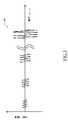
特に図1を参照すると、本開示の一実施形態によるソリューションを実践するために使用することができる超音波スキャナ100の図的記述が示されている。 With particular reference to FIG. 1, a pictorial description of an
超音波スキャナ100は、中央ユニット105、および、それに接続されているアレイタイプの手持ち式送受信イメージングプローブまたはトランスデューサ110を備える。トランスデューサ110は、(たとえば、4〜20Hzのレートで)解剖学的画像のフレームを生成するように意図されている一連の超音波を送信するための送信機と、選択される走査平面内の超音波の反射から(無線周波数、RF)エコー信号を受信するための受信機とを備え、この目的のために、トランスデューサ110には、上述したパルス−エコーモードにおいてトランスデューサ110を使用することを可能にする送受信マルチプレクサが設けられている。 The
中央ユニット105は、超音波スキャナ100の動作を制御する電子回路(たとえば、マイクロプロセッサ、作業メモリおよびハードディスクドライブ)が搭載されているマザーボード115を収容している。その上、1つまたは複数のドーターボード(全体として参照符号120で示す)がマザーボード115内でプラグ接続されており、ドーターボード120は、トランスデューサ110を駆動し、エコー信号を処理するためのさらなる電子回路を提供する。中央ユニット105にはまた、リムーバブルディスク130(CDまたはDVDなど)を読み出し/書き込みするためのドライブ125も設けられている。進行中の治療/診断プロセスに関係する情報を表示するためのモニタ135が中央ユニット105に接続されている。 The
超音波スキャナ100の動作はキーボード140(従来の様式で中央ユニット105に接続されている)を用いて制御され、好ましくは、キーボード140には、モニタ135上のポインタ(この図には示されていない)の位置を操作するために使用されるトラックボール145が設けられている。特に、キーボード140は、許容される周波数範囲(たとえば、1〜50MHz)内の超音波の所望の(中心)周波数、および、許容される範囲内の(たとえば、1mV〜10Vの送信電圧によって規定される振幅に対応する)超音波を生成する超音波システムの所望の送信パワーを設定することを可能にする。ほとんどの超音波スキャナにおいて、送信パワーを絶対的に設定することは可能ではなく、その無次元のパワーレベルとして相対的にしか設定することが可能でない。たとえば、パワーレベルは最大値のような基準値に対してdB単位で表現される(たとえば、−40dB〜0dB)。 The operation of the
超音波スキャナ100は、それぞれ患者155の身体部分150を処置および分析するために治療適用および診断適用において使用することができる。この目的のために、一般的に(超音波)造影剤が患者155に投与される。 The
造影剤は、超音波反射体として作用する粒子を含む。たとえば、造影剤は、液体キャリア中の気体充填気泡の懸濁液であり、気体充填気泡は、それらが患者155の血管系内で存続することを可能にするが、同時に、それらが毛細血管を通過することを可能にするように、約0.1〜5μmの直径を有する。気体充填気泡は一般的に、リン脂質、乳化剤、油、増粘剤、糖類、タンパク質またはポリマーを含む様々な系の中に気体またはその前駆体を混入または封入することによって安定化され、安定化された気体充填気泡は一般的に、マイクロベシクルと称される。特に、水媒体内で分散されており、界面活性剤(すなわち、両親媒性材料)を含む非常に薄いエンベロープによって気液界面において境界されているマイクロベシクルは、微小気泡としても知られている。代替的に、脂質または(天然もしくは合成)ポリマーによって形成される固体材料エンベロープによって包囲されているマイクロベシクルは、マイクロバルーンまたはマイクロカプセルとしても知られている。別の種類の造影剤は、ポリマーまたは他の固体の多孔質微小粒子の懸濁液を含み、これは、微小粒子の細孔内に封じ込められた又はそれらの表面に吸着された気体の気泡を担持する。マイクロベシクル、特に微小気泡およびマイクロバルーンの適切な水性懸濁液、およびその調製品の例は、欧州特許出願公開第0458745号明細書、国際公開第91/15244号パンフレット、欧州特許出願公開第0554213号明細書、国際公開第94/09829号パンフレットおよび国際公開第95/16467号パンフレット(それらの開示全体が参照により本明細書に組み込まれる)に記載されている。マイクロベシクルを含む商用の造影剤の一例が、Bracco International BVによるSonoVue(商標)である。 Contrast agents include particles that act as ultrasound reflectors. For example, the contrast agent is a suspension of gas-filled bubbles in a liquid carrier, which allows them to persist in the vasculature of the
たとえば、造影剤は、ボーラス、すなわち、短期間(2〜20秒程度)にわたって注射器によって手で与えられる単回投与として患者155の静脈内に投与される。造影剤は、身体部分150に灌流するように、患者155の血管系内を循環する。同時に、トランスデューサ110が身体部分150の領域内で患者155の皮膚と接触され、一連の超音波がそこに印加される。治療適用において、超音波は、身体部分150に対する生物学的効果(たとえば、音響流または音響キャビテーション)を意図的に誘発する。診断適用においては、代わりに、超音波に応答して記録されるエコー信号が身体部分150の表現を提供する。 For example, the contrast agent is administered to the
(以下に詳細に説明するような)本開示の一実施形態によるソリューションにおいては、推定値が決定され、推定値は、身体部分150に所望の音圧を印加するために必要とされるパワーレベル、特定の目標パワーレベルが設定されているときに身体部分150に実際に印加される音圧、患者155内でトランスデューサ110と身体部分150との間で発生する音響減衰、および/または、患者内で異なる身体部分150間(たとえば、異なる深さにおいて)で発生する音響減衰を示す。この目的のために、超音波に対する造影剤粒子の非基本波(たとえば、低調波)応答が利用され、実際、この非基本波応答内の一般的なパターンが、上述した推定にとって有益な情報を提示する。 In a solution according to an embodiment of the present disclosure (as described in detail below), an estimate is determined, which is the power level required to apply the desired sound pressure to the
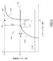
ここで図2を参照すると、造影剤粒子から超音波への低調波応答の種々の例が示されている。 Referring now to FIG. 2, various examples of subharmonic response from contrast agent particles to ultrasound are shown.
一般的に、低調波応答は、超音波によって造影剤粒子に印加される音圧の関数としてのエコー信号の低調波成分のレベル(たとえば、超音波の基本/送信周波数の2分の1(1/2)に等しい周波数を有する成分のパワー)によって定義される。低調波応答は、横軸上の音圧(対数スケールにおけるkPa単位)に対して縦軸上に低調波レベル(基準値に対するdB単位)をプロットしているグラフにおいて表すことができ、対応する一連の点が各々、対応する音圧が造影剤に印加されるときに記録される低調波レベルを示す。 In general, the subharmonic response is the level of the subharmonic component of the echo signal as a function of the sound pressure applied to the contrast agent particle by the ultrasound (for example, one half (1/2 of the fundamental / transmission frequency of ultrasound) Defined by the power of the component having a frequency equal to / 2). The subharmonic response can be represented in a graph plotting subharmonic levels (in dB relative to a reference value) on the vertical axis against sound pressure on the horizontal axis (in kPa in logarithmic scale) and the corresponding series Each point represents a subharmonic level that is recorded when the corresponding sound pressure is applied to the contrast agent.
特に、この図は、3つの低調波応答205a、205bおよび205cを示している。低調波応答205a〜205cの各点は、対応する音圧について記録されている低調波レベルの平均を表し(誤差バーはそれらの標準偏差を示す)、特に、低調波応答205a、205bおよび205cは、種々の(周囲)静水圧、特に、それぞれ3mmHg、60mmHgおよび120mmHgにおいて実施されている測定に関係する。 In particular, this figure shows three
低調波応答205a〜205cは、測定ノイズの主要な効果のために重要でない、ノイズ部分207n(たとえば、50kPaを下回る)として参照される初期部分を含む。低調波レベルは静水圧に強く依存することが知られているため、代わりにより高い音圧を考慮すると、これは、感受性部分207s(たとえば、50kPA〜350kPa)として参照される、低調波応答205a〜205cの中心部分の間の差によって確認される。たとえば、静水圧から低調波レベルの依存性は、Frinking PJA他「Subharmonic scattering of phospholipid−shell microbubbles at low acoustic pressure amplitude」(IEEE Trans.Ultrason.Ferroelectr.Freq.Control,Vol.57,No8,August 2010)(その開示全体が参照により本明細書に組み込まれる)において言及されているように、人体内の心臓腔または大きな血管における非侵襲的静水圧測定に利用することができる。しかしながら、驚くべきことに、遷移音圧(たとえば、約300〜400kPa)よりも高い音圧に関して、低調波レベルは、静水圧に対して実質的に無反応であることが分かっており、これは、図面において、破壊部分207d(350kPaのような、この遷移音圧を上回る)として参照される、低調波応答205a〜205cの最後の部分の良好な重なりによって示されている。 The
その上、理論的には、低調波応答は、超音波の送信と対応するエコー信号の受信の両方において、音響減衰(たとえば、dB単位で表現される)に依存する。事実、送信経路において、(超音波スキャナのトランスデューサから対象の深さまでの)音響減衰は、造影剤に印加される音圧を低減し、受信経路においては、代わりに、(対象の深さから超音波スキャナのトランスデューサまでの)音響減衰は、記録される低調波レベルを低減する。同様に、造影剤もまた音響を減衰させるように作用し得、伝播(すなわち、送信および/または受信)経路に沿って存在するときに、その濃度に比例する音響減衰を引き起こす。 Moreover, in theory, the subharmonic response relies on acoustic attenuation (e.g., expressed in dB), both at the transmission of the ultrasound and at the reception of the corresponding echo signal. In fact, in the transmit path, acoustic attenuation (from the transducer of the ultrasound scanner to the depth of interest) reduces the sound pressure applied to the contrast agent, and in the receive path, instead (over the depth of interest) Acoustic attenuation) down to the transducer of the acoustic scanner reduces the level of subharmonics recorded. Similarly, contrast agents can also act to attenuate the sound, causing an acoustic attenuation that is proportional to its concentration when present along the propagation (i.e., transmit and / or receive) path.
音圧が横軸内で対数スケールで表現されるとき、任意の低調波応答の破壊部分は、(静水圧、音響減衰および造影剤濃度にかかわりなく)一定のパターンを有し、音響減衰および造影剤濃度は、そのシフト、すなわち、送信経路上での減衰を反映する水平シフト、および、受信経路上での減衰を反映する垂直シフトを引き起こすのみである。 When sound pressure is expressed on a logarithmic scale in the horizontal axis, the disrupted part of any subharmonic response has a constant pattern (regardless of hydrostatic pressure, acoustic attenuation and contrast agent concentration), acoustic attenuation and contrast The agent concentration only causes that shift, a horizontal shift that reflects the attenuation on the transmit path, and a vertical shift that reflects the attenuation on the receive path.
同様の考慮事項が、低調波応答が超音波スキャナのパワーレベルの関数としての低調波レベルによって表現されるときに適用される。この事例において、低調波応答は、横軸上のパワーレベルに対して縦軸上に低調波レベルをプロットしている(それらは両方ともdB単位である)グラフ(この図には示されていない)において表現することができ、対応する一連の点が各々、超音波スキャナが対応するパワーレベルに設定されているときに記録される低調波レベルを示している。上記のように、種々の静水圧に関する低調波応答は、重要でないノイズ部分、静水圧に強く依存する中心部分、および、静水圧に実質的に無反応である破壊部分を含み、任意の低調波応答の破壊部分は(静水圧、音響減衰および造影剤濃度にかかわりなく)一定のパターンを有し、音響減衰および造影剤濃度は、その(水平および垂直)シフトを引き起こすのみである。 Similar considerations apply when subharmonic response is represented by subharmonic levels as a function of ultrasound scanner power levels. In this case, the subharmonic response plots subharmonic levels on the vertical axis against power levels on the horizontal axis (they are both in dB) graph (not shown in this figure) And the corresponding series of points each indicate the subharmonic level recorded when the ultrasound scanner is set to the corresponding power level. As noted above, the subharmonic response for various hydrostatic pressures includes any nonharmonic parts including noise portions that are not important, a central portion that is strongly dependent on hydrostatic pressure, and fracture portions that are substantially insensitive to hydrostatic pressure. The disrupted portion of the response has a constant pattern (regardless of hydrostatic pressure, acoustic attenuation and contrast agent concentration), and the acoustic attenuation and contrast agent concentration only cause its (horizontal and vertical) shifts.
結果として、測定(低調波)応答と基準(低調波)応答との間で比較を行うことができる。特に、以下に詳細に説明するように、測定応答は、超音波を身体部分に(in−vivoで)印加するために使用される超音波スキャナのパワーレベルの関数として測定される(測定)エコー信号の低調波レベルを表現し、一方で、基準応答は、音圧またはパワーレベルの関数として提供される(基準)エコー信号の低調波レベルを表現し、たとえば、基準応答は、造影剤を含むin−vitro較正構造において音圧および/またはパワーレベルの関数として測定される(較正)エコー信号の低調波レベルを表現する較正応答であり得、または、さらなる(測定)エコー信号(たとえば、異なる深さにおいて測定される)の低調波レベルを表現するさらなる測定応答であり得る。 As a result, a comparison can be made between the measured (subharmonic) response and the reference (subharmonic) response. In particular, as described in more detail below, the measurement response is measured as a function of the power level of the ultrasound scanner used to apply the ultrasound to the body part (in-vivo) (measurement) echo A sub-harmonic level of the signal is expressed, while the reference response represents a sub-harmonic level of the (reference) echo signal provided as a function of sound pressure or power level, eg, the reference response contains a contrast agent It may be a calibration response that represents the subharmonic level of the (calibration) echo signal measured as a function of sound pressure and / or power level in the in-vitro calibration structure, or may be a further (measurement) echo signal (eg different depths) Can be a further measurement response that represents subharmonic levels of
ここで、図3〜図6を参照すると、本開示の一実施形態によるソリューションの一適用例が示されている。 Referring now to FIGS. 3-6, one application of the solution according to one embodiment of the present disclosure is shown.
図3から開始して、較正/測定応答を記録するために使用することができる超音波が、較正/測定励起信号405によって規定され、これは、図面において、横軸の時間(μs単位)に対して縦軸上にその振幅(mV単位)をプロットすることによって表されている。較正/測定励起信号405は、相対的に狭い帯域を有する一連のトーンバーストパルス(たとえば、1〜10MHz、好ましくは2〜6MHzの周波数を有する)を含み、結果としてもたらされる超音波パルスの振幅は、超音波スキャナのパワーレベルを経時的に、較正/測定範囲(たとえば、20dB超、好ましくは30dB超)において変化させることによって変調される。 Starting from FIG. 3, an ultrasound wave that can be used to record a calibration / measurement response is defined by the calibration /
較正応答を決定するために、較正励起信号405がin−vitroで較正構造(図面には示されていない)に印加される。較正構造は、造影剤の(たとえば、水の中の)懸濁液であり、造影剤は、想定的に低い濃度を有し、任意の実質的な音響減衰も回避する(たとえば、5dB/cmを下回る、好ましくは、2dB/cmを下回る)。(超音波スキャナの対応するパワーレベルによって規定されるものとしての)較正励起信号405の各超音波パルスについて、それに応答して受信される較正エコー信号の低調波レベル、および、造影剤に印加される(たとえば、水中聴音器を用いて測定される)実際の音圧が記録される。他方、測定応答を決定するために、測定励起信号405がin−vivoで(造影剤を灌流されている)身体部分に印加され、(超音波スキャナの対応するパワーレベルによって規定されるものとしての)測定励起信号405の各超音波パルスについて、それに応答して受信される測定エコー信号の低調波レベルが記録される。 A
図4に移って、本開示の一実施形態において、測定データの、基準データとの比較は、測定応答および基準応答を適合させる同じモデル関数の対応するインスタンス(それぞれ測定関数および基準関数として参照され、基準関数は、較正応答を適合させるときは較正関数であり得、または、さらなる測定応答を適合させるときはさらなる測定関数であり得る)に基づく。一般的に、モデル関数は、低調波レベルを、対数スケール(たとえば、dB単位)でのパワーレベルまたは音圧の関数として表現する。特にパワーレベルに関して、モデル関数は、対応する曲線410によって表される(横軸上のパワーレベルに対して縦軸上に低調波レベルをプロットする図において、それらは両方ともdB単位で表される)。モデル関数(すなわち、その曲線410)は、対応する低調波応答のノイズ部分を表すノイズ区間410n、感受性部分を表す感受性区間410s、および、破壊部分を表す破壊区間410dを含む。モデル関数は、全体的にS字形状を有し得る。特に、モデル関数は、実質的に一定の第1の値(ノイズ区間410nを規定する)を有する(最初の)第1の一定の区画を含む。モデル関数はその後、第1の値よりも高い実質的に一定の第2の値を有する第2の一定の区画と、凹形状を有する、実質的に単調に増大する、第1の一定の区間と第2の一定の区間との間の第1の増大する区間(感受性区間410sを規定する)とを含む。最後に、モデル関数は、第2の値よりも高い実質的に一定の第3の値を有する(最後の)第3の一定の区画と、凹形状を有する、実質的に単調に増大する、第2の一定の区間と第3の一定の区間との間の第2の増大する区間(破壊区間410dを規定する)とを含む。より形式的には、モデル関数は、第1の/第2の/第3の一定の区間において実質的にゼロに等しい一次導関数を有し、第1の/第2の増大する区間においては実質的にゼロよりも高い(または等しい)一次導関数を有する(モデル関数はまた、第1の/第2の増大する区間において、負である二次導関数をも有し得る)。 Turning to FIG. 4, in one embodiment of the present disclosure, comparison of measured data to reference data is performed using corresponding responses of the same model function to which the measurement response and the reference response are fitted (referred to as the measurement function and the reference function, respectively) The reference function may be based on the calibration function when fitting the calibration response or may be based on the further measurement function when fitting the further measurement response. In general, the model function represents subharmonic levels as a function of power level or sound pressure on a logarithmic scale (e.g., in dB). Model functions are represented by the corresponding curve 410 (with respect to power levels on the horizontal axis plotted against subharmonic levels on the vertical axis, both of them in dB), in particular with respect to power levels ). The model function (i.e., its curve 410) includes a
たとえば、モデル関数は、以下の式によって定義することができる。
特に、モデル関数SH(PL)は、パワーレベルを表す独立変数PL、および、低調波レベルを表す従属変数SHを有する(それらは両方ともdB単位)。モデル関数SH(PL)は、そのノイズ区間410n、感受性区間410sおよび破壊区間410dを規定する3つの項の和から構成されている。第1の項(破壊区間410dを表す)において、パラメータKdは波形率(dB単位)であり、パラメータΓPLは破壊区間410dの(下降する)垂直漸近線415のパワーレベルであり、パラメータΓSHは破壊区間410dの(増大する)水平漸近線420の低調波レベルである(すなわち、それぞれ
dB単位)であり、パラメータΔPLは、パラメータΓPLと、低調波レベルが感受性区間410sの(増大する)水平漸近線425(すなわち、
0のパワーレベル(すなわち、パラメータΓSH)と水平漸近線425のパワーレベル(すなわちSHo)との間の差である。第3の項(ノイズ区間410nを表す)において、パラメータKnは、測定ノイズ(dB単位)を示す。各測定/基準関数はこのとき、モデル関数SH(PL)を測定/基準応答に最良に適合させるパラメータKd、ΓPL、ΓSH、Ks、ΔPL、ΔSHおよびKnの対応する値によって定義される。In particular, the model function SH (PL) has an independent variable PL, which represents the power level, and a dependent variable SH, which represents the subharmonic level (both in dB). The model function SH (PL) is composed of the sum of three terms that define its
(in dB), the parameter ΔPL is the parameter PLPL, and the subharmonic level is an (increased) horizontal asymptote 425 (ie,
It is the difference between a power level of 0 (i.e. parameter Γ SH) and a power level of horizontal asymptote 425 (i.e. SHo). In the third term (representing the
同様の考慮事項が、低調波レベルを音圧の関数として表現するモデル関数に適用され、この事例において、モデル関数SH(AP)は上記のように定義することができ、独立変数APは音圧を表し、パラメータΓAPは、破壊区間の垂直漸近線の音圧を表し、パラメータΔAPは、パラメータΓAPと、低調波レベルが感受性区間の水平漸近線を3dB下回る音圧との間の差を表す。 Similar considerations apply to model functions that represent subharmonic levels as a function of sound pressure, and in this case, the model function SH (AP) can be defined as above, and the independent variable AP is sound pressure. The parameter ΓAP represents the sound pressure of the vertical asymptote of the breakup interval, and the parameter ΔAP represents the difference between the parameter ΓAP and the sound pressure of the subharmonic level 3 dB below the horizontal asymptote of the sensitive interval.
上記に照らして、任意の測定/基準関数の破壊区間(モデル関数の破壊区間410dに対応する)は、(静水圧、音響減衰および造影剤濃度にかかわりなく)一定の形状を有し、破壊区間は、対応する音響減衰および造影剤濃度に従って(実質的に固定的に)シフトするのみである。それゆえ、本開示の一実施形態において、測定関数の、基準関数との比較は単純に、その破壊区間の特徴点(それぞれ測定関数および基準関数の測定点および基準点として参照され、基準点は、較正関数の較正点、または、さらなる測定関数のさらなる測定点であり得る)に基づく。各測定点/基準点は、対応する測定/基準関数の破壊区間の位置を一義的に識別する。たとえば、概してモデル関数SH(PL)の曲線410を参照すると、特徴点は、感受性区間410sと破壊区間410dとの間の交差点に対応して規定され得る。特に、特徴点は、破壊区間410dの垂直漸近線415と、水平漸近線420との交差点(図において十字430によって示されている)によって規定することができ、このとき、特徴点は座標(ΓPL,ΓSH)を有し、パラメータΓPLは特徴パワーレベルを規定する(同様の考慮事項が、特徴点が座標(ΓAP,ΓSH)を有するときに適用され、パラメータΓAPは特徴音圧を規定する)。 In light of the above, the failure interval of any measurement / reference function (corresponding to the
図5に移って、例示的な較正応答(この図には示されていない)は、(較正)曲線510cによって表される較正関数(SHc(PL)によって示されている)によって適合される。代わりに、例示的な測定応答(この図には示されていない)は、(測定)曲線510mによって表される測定関数(SHm(PL)によって示されている)によって適合される。一般的に、測定応答は、較正応答に関連して減衰する(超音波スキャナのトランスデューサと身体部分との間に介在する解剖学的構造によって引き起こされる患者内の減衰のため、および/または、造影剤の可能性として相対的に高い濃度のため)。それゆえ、曲線510mは、曲線510cに対して右向きに(ここで、送信経路における音響減衰のために同じ低調波レベルを得るためにより高いパワーレベルが必要とされるため)および下向きに(受信経路における音響減衰のために同じパワーレベルから得られる低調波レベルがより低くなるため)にシフトされる。 Turning to FIG. 5, an exemplary calibration response (not shown in this figure) is fitted by the calibration function (indicated by SHc (PL)) represented by the (calibration)
較正関数SHc(PL)は、(較正)十字530cによって表される較正点(ΓPLc,ΓSHc)を有する。較正点(ΓPLc,ΓSHc)は、特徴パワーレベルΓPLc(較正パワーレベルとして参照される)を識別し、これは、較正構造において測定されるものとして、造影剤に対する対応する特徴音圧ΓAPc(較正音圧として参照される)の印加を引き起こす。測定関数SHm(PL)は、(測定)十字530mによって表される測定点(ΓPLm,ΓSHm)を有する。測定点(ΓPLm,ΓSHm)は、特徴パワーレベルΓPLm(測定パワーレベルとして参照される)を識別し、これは、同じ較正音圧ΓPAcを身体部分に印加するために必要とされ、患者内で発生する音響減衰のために、較正パワーレベルΓPLcよりも高い(dB単位で表現したとき、Att=ΓPLm−ΓPLcに等しい)。 The calibration function SHc (PL) has calibration points (ΓPLc, ΓSHc) represented by the (calibration)
別の例示的な測定応答(この図には示されていない)は、(測定)曲線510m’によって表される測定関数(SHm’(PL)によって示されている)によって適合される。この測定応答は、上記の測定応答と比較してより大きく減衰されており(たとえば、より多くの解剖学的構造が間に介在しており、かつ/または、造影剤の濃度がより高いため)、それによって、曲線510m’は、曲線510mがそうであるよりも(曲線510cに対して)さらに右下にシフトされている。測定関数SHm’(PL)は、(測定)十字530m’によって表される測定点(ΓPLm’,ΓSHm’)を有し、これは、測定パワーレベルΓPLm’を識別する。この事例において、患者内の音響減衰がより大きくなっているため(dB単位で表現したとき、Att’=ΓPLm’−ΓPLcに等しく、減衰Attと比較してΔAtt=ΓPLm’−ΓPLmだけ増大している)、同じ較正音圧ΓPAcを身体部分に印加するために、より高い測定パワーレベルΓPLm’が必要とされる。 Another exemplary measurement response (not shown in this figure) is fitted by the measurement function (indicated by SHm '(PL)) represented by the (measurement)
図6に移って、超音波スキャナの初期化段階の間に、関連する較正パワーレベルΓPLcおよび較正音圧ΓAPcを決定することができ(たとえば、ΓPLc=23dBおよびΓAPc=200kPa)、この操作は、特定の環境条件(たとえば、超音波スキャナおよび造影剤のタイプの設定)に対して1度だけ必要とされる。 Turning to FIG. 6, during the initialization phase of the ultrasound scanner, the associated calibration power level Γ PLc and calibration sound pressure Γ APc can be determined (eg, Γ PLc = 23 dB and Γ AP c = 200 kPa), this operation being It is only required once for certain environmental conditions (e.g. ultrasound scanner and contrast agent type settings).
(造影剤を灌流されている)身体部分からの測定応答605が記録される。測定応答605は、対応する(測定)曲線610mによって表される測定関数によって適合される。測定関数は、(測定)十字630mによって表される測定点を有し、これは、対応する測定パワーレベルΓPLmを識別する(たとえば、ΓPLm=25dB)。 The measured
測定パワーレベルΓPLmおよび較正音圧ΓAPcは(問題の例においてはdB単位における、造影剤に印加される超音波の音圧とパワーとの間の既知の二次関係、および、超音波スキャナの送信パワーとパワーレベルとの間の既知の関係と組み合わせて)、超音波スキャナの任意のパワーレベルについて身体部分に実際に印加される音圧、または逆に、任意の音圧を身体部分に実際に印加するために必要とされる超音波スキャナのパワーレベルを推定するために使用することができる。特に、目標音圧APtが身体部分に適用されるべきであるとき、超音波スキャナは、以下によって得られる目標パワーレベルPLtに設定される。
たとえば、この事例において、超音波スキャナを目標パワーレベル
きる。For example, in this case, the ultrasound scanner
本開示の一実施形態による上述した技法は、in−situで印加される実際の音圧を高精度で決定することを可能にする。この結果は、さらにはin−vivo条件において、非侵襲的に、遠隔しても達成することができる。 The above described technique according to an embodiment of the present disclosure enables to determine with high accuracy the actual sound pressure applied in-situ. This result can also be achieved non-invasively and remotely in in-vivo conditions.
そのようにして得られた身体部分に印加される音圧の推定値は、治療適用においては、任意の所望の音圧を造影剤粒子に印加するように超音波スキャナを制御するために使用することができる。特に、造影剤粒子の安定した可逆的な振動が必要とされるとき(たとえば超音波血栓溶解において)、これは、超音波に過剰に晒されることに起因する一切の望ましくない副次的影響を同時に回避し、または、少なくとも実質的に制限しながら、治療適用(たとえば、細胞溶解)の効率を著しく増大させる。 The estimate of the sound pressure applied to the body part so obtained is used in therapeutic applications to control the ultrasound scanner to apply any desired sound pressure to the contrast agent particles be able to. In particular, when a stable, reversible oscillation of the contrast agent particles is required (e.g. in ultrasound thrombolysis), this has any undesirable side effects due to excessive exposure to ultrasound. At the same time, the efficiency of the therapeutic application (eg, cell lysis) is significantly increased, while at the same time avoiding or at least substantially limiting.
代わりに、測定パワーレベルΓPLmおよび較正パワーレベルΓPLcを、患者内でトランスデューサから身体部分までに発生する音響減衰(以下、総音響減衰として参照される)を推定するために使用することができる。特に、総音響減衰Attは単純に、測定パワーレベルΓPLmと較正パワーレベルΓPLcとの間の差によって与えられる(すなわち、Att=ΓPLm−ΓPLc)。たとえば、この事例において、総音響減衰はAtt=25−23=2dBに等しい。 Alternatively, the measured power level Γ PLm and the calibrated power level Γ PL c can be used to estimate the acoustic attenuation (hereinafter referred to as total acoustic attenuation) that occurs in the patient from the transducer to the body part. In particular, the total acoustic attenuation Att is simply given by the difference between the measured power level Γ PLm and the calibration power level Γ PL c (ie Att = Γ PL m-Γ PL c). For example, in this case, the total sound attenuation is equal to Att = 25-23 = 2 dB.
加えてまたは代替形態において、なお造影剤を灌流されているさらなる身体部分からの(たとえば、同じ臓器の異なる深さにおける)さらなる測定応答を記録し、これを、さらなる測定パワーレベルΓPLm’(たとえば、患者内で1cmだけより深い箇所におけるΓPLm’=25.3dB)を識別するさらなる測定点(この図には示されていない)を有するさらなる測定関数によって適合することも可能である。 In addition or in the alternative form, a further measurement response (eg at different depths of the same organ) from a further body part which is still perfused with contrast agent is recorded, this is further measured power level ΓPLm '(eg It is also possible to fit by means of a further measurement function with a further measurement point (not shown in this figure) which identifies ΓPLm '= 25.3 dB) at a point deeper than 1 cm in the patient.
これら2つの測定パワーレベルΓPLmおよびΓPLm’は、上述したように、患者内で対応する身体部分間で発生する音響減衰(以下、部分音響減衰として参照される)を推定するために使用することができる。特に、部分音響減衰ΔAttは単純に、測定パワーレベルΓPLmとΓPLm’との間の差によって与えられる(すなわち、ΔAtt=ΓPLm−ΓPLm’)。たとえば、この事例において、問題の臓器の1cmの部分音響減衰はΔAtt=25.3−25=0.3dBに等しい。 These two measured power levels ΓPLm and ΓPLm 'may be used to estimate the acoustical attenuation (hereinafter referred to as partial acoustical attenuation) generated between corresponding body parts in the patient, as described above it can. In particular, the partial acoustic attenuation ΔAtt is simply given by the difference between the measured power levels' PLm and 'PLm' (ie, ΔAtt = 'PLm-'PLm'). For example, in this case, the 1 cm partial acoustic attenuation of the organ in question is equal to ΔAtt = 25.3−25 = 0.3 dB.
本開示の一実施形態による上述した技法は、in−situで発生する実際(総/部分)音響減衰を高精度で決定することを可能にする。この結果は、さらにはin−vivo条件において、非侵襲的に、遠隔しても達成することができる。 The above described techniques according to an embodiment of the present disclosure allow to determine with precision the actual (total / partial) acoustic attenuation that occurs in situ. This result can also be achieved non-invasively and remotely in in-vivo conditions.
そのようにして得られた患者内で発生する音響減衰の推定値は、診断適用において(たとえば、身体部分をその音響減衰に従って特徴付けるために)使用することができる。 The estimate of the acoustic attenuation generated in the patient so obtained can be used in diagnostic applications (e.g. to characterize a body part according to its acoustic attenuation).
ここで、図7を参照すると、本開示のさらなる実施形態によるソリューションの一適用例が示されている。 Referring now to FIG. 7, one application of the solution according to a further embodiment of the present disclosure is shown.
この事例においては、超音波スキャナのパワーレベルを経時的に、測定応答の破壊部分に実質的に対応する制限された測定範囲内で変化させることによって、(測定応答を記録するために使用される)測定励起信号が生成され、この目的のために、超音波スキャナのパワーレベルは経時的に、対応する閾値よりも上(たとえば、20dBよりも上、好ましくは23dBよりも上)でのみ変化される。(その破壊部分に実質的に制限される)測定応答705が、この測定励起信号に応答して記録される。測定応答705は、(測定)十字730mによって表される測定点を有する対応する(測定)曲線710mによって表される測定関数(その破壊部分に実質的に制限される)によって適合される。しかしながら、この事例において、測定関数は、単純化されたモデル関数のインスタンスである。たとえば、モデル関数は、以下の式によって定義されるように、ノイズ区間および破壊区間を規定する項のみを含み得る。
これによって、適合の計算複雑度が低減し、超音波スキャナの制限された動的範囲によってさえ、同じ技法を適用することが可能である。いずれにせよ、測定応答の、基準応答とのその比較について最も重要な部分(すなわち、破壊部分)が常に考慮に入れられるため単純化されたモデル関数によって影響される精度の損失は大きなものではない。 This reduces the computational complexity of the fit and allows the same techniques to be applied even with the limited dynamic range of the ultrasound scanner. In any case, the loss of accuracy affected by the simplified model function is not significant, as the most important part of the measured response (that is, the broken part) is always taken into account for its comparison with the reference response .
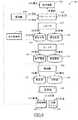
ここで図8を参照すると、本開示の一実施形態によるソリューションを実装するために使用することができる主な構成要素の役割を表す協調図が示されている。これらの(ソフトウェアおよび/またはハードウェア)構成要素は、全体として参照符号800で示されている。特に、ソフトウェア構成要素(プログラムおよびデータ)は一般的に、大容量記憶装置に記憶され、オペレーティングシステムおよび他のアプリケーションプログラム(この図には示されていない)とともに、プログラムが作動しているときに、超音波スキャナの作業メモリに(少なくとも部分的に)ロードされる。プログラムは最初に、たとえば取り外し可能記憶装置またはネットワークから大容量記憶装置にインストールされる。これに関連して、各ソフトウェア構成要素は、指定の論理機能を実施するための1つまたは複数の実行可能命令を含む、モジュール、セグメント、またはコードの一部分を表すことができる。特に、この図は、構成要素800の静的構造とそれらの動的挙動の両方を(記号「A」が前に置かれている通し番号によって示されている、各々が対応する動作を表す一連の交換されるメッセージによって)記述している。 Referring now to FIG. 8, a collaborative view is shown that represents the role of the main components that can be used to implement the solution in accordance with an embodiment of the present disclosure. These (software and / or hardware) components are indicated generally by the
TX/RXコントローラ803が、トランスデューサを制御する。たとえば、TX/RXコントローラ803は、各取得時点において超音波を生成するための送信ビーム形成器およびパルサを有するTXコントローラを備える。TX/RXコントローラ803は、(選択される走査平面内の対応する箇所の)各取得時点において対応する(アナログRF)エコー信号を受信するためのRXプロセッサをさらに備える。RXプロセッサは、アナログRFエコー信号を前置増幅し、予備時間−利得補正(TGC)を適用し、アナログRFエコー信号はその後、アナログ/デジタル変換器(ADC)によってデジタル値に変換され、受信ビーム形成器を通じて組み合わされて集束ビーム信号になる。そのようにして得られたデジタルRFエコー信号は、好ましくは、さらなるデジタルアルゴリズムおよび他の線形または非線形信号調整器(例えば、ビーム形成後のTGC)を通じて処理される。TX/RXコントローラ803は、各取得時点の解剖学的画像(対応する箇所のエコー信号に基づくピクセル値の行列を含む)を生成するようにデジタルRFエコー信号を復調、対数圧縮および走査変換してビデオフォーマットにするビデオ変換器をさらに備える。 A TX / RX controller 803 controls the transducer. For example, the TX / RX controller 803 comprises a TX controller with transmit beamformer and pulser for generating ultrasound at each acquisition time. The TX / RX controller 803 further comprises an RX processor for receiving a corresponding (analog RF) echo signal at each acquisition instant (of the corresponding location in the selected scan plane). An RX processor pre-amplifies the analog RF echo signal and applies spare time-gain correction (TGC), which is then converted to digital values by an analog-to-digital converter (ADC) and received beam Combine through the former into a focused beam signal. The digital RF echo signal so obtained is preferably processed through further digital algorithms and other linear or non-linear signal conditioners (e.g. TGC after beamforming). The TX / RX controller 803 demodulates, logarithmically compresses and scan converts the digital RF echo signal to generate an anatomic image at each acquisition time point (including a matrix of pixel values based on the echo signal at the corresponding location). It further comprises a video converter for converting to video format.
超音波スキャナは、(較正応答を使用する事例において)新たな造影剤が使用されなければならないときはいつでも初期化され、超音波スキャナの設定(たとえば、その周波数)が変更され、または、その動作に影響を与える超音波スキャナの任意の部分(たとえば、トランスデューサ)が交換される。この段階において、超音波スキャナの操作者は、造影剤のための較正構造を準備し、水中聴音器806(較正構造と関連づけられる)を超音波スキャナに接続する。操作者はその後、較正構造と接触させてトランスデューサを配置し、初期化コマンドを入力する。それに応答して、変調器809がTX/RXコントローラ803を、較正構造の各箇所に較正励起信号を印加するように駆動する(動作「A1.印加」)。各箇所に対する較正励起信号に応答して受信される(デジタルRF)較正エコー信号はレコーダ812に渡され、レコーダは、対応する低調波成分を得るように、この信号を(較正励起信号の)超音波の基本周波数の約半分にバンドパスフィルタリングする。一実施形態において、較正励起信号は、反対の符号を有する、超音波パルスの2つのバーストを含み、2つのバーストの各パルス対は迅速に連続して送信され、この事例において、2つの対応する較正エコー信号が(バンドパスフィルタリングの前に)受信および合計される。それゆえ、2つのバーストの各パルス対からもたらされる2つの較正エコー信号の合計において、それらの線形成分(組織に起因する)が打ち消し合い、一方で、それらの非線形成分(振幅の等しい正および負の音圧に別様に応答する造影剤に起因する)が増大する。これによって、低調波応答を汚染する可能性がある(また、単純なバンドパスフィルタリングによっては抑制されない場合がある)任意の線形成分が大幅に低減され、それによって、応答対雑音比、したがって、本技法の感受性が向上する。各取得時点について、レコーダ812は、(超音波スキャナの対応するパワーレベルについてのエコー信号の低調波レベルを規定する)すべての箇所の低調波成分のパワーの平均を計算する。レコーダ812はその後、各取得時点のレコードを保存し、対応するパワーレベルおよび低調波レベルを較正応答テーブル815に記憶する(動作「A2.記録」)。同時に、水中聴音器806が、各取得時点において造影剤に印加される音圧を測定し、この音圧が、較正応答テーブル815の対応するレコードに加えられる(動作「A3.測定」)。このように、較正応答テーブル815の各レコードは、対応する対になった音圧/低調波レベル(音圧を推定するためのもの)および/またはパワーレベル/低調波レベル(音響減衰を推定するためのもの)によって規定されるものとしての、較正応答の点を表す。フィッタ818が、較正応答テーブル815にアクセスする。フィッタ815は、対応する較正関数を得るように、(たとえば、周知の誤差最小化アルゴリズムを適用することによって)モデル関数のインスタンスによってその較正応答の点を適合させる。フィッタ818は、較正関数を定義するパラメータの値(すなわち、Kd、ΓAP/ΓPL、ΓSH、Knおよび場合によってKs、ΔAP/ΔPL、ΔSH)を較正関数テーブル821に保存する(動作「A4.適合」)。抽出器824が、較正関数テーブル821および較正応答テーブル815にアクセスして較正音圧ΓAPcおよび/または較正パワーレベルΓPLc(それぞれ較正関数テーブル821からの較正関数の、または、較正応答テーブル815からの対応するレコード内のパラメータΓPLまたはΓAPの値によって規定されるもの)を抽出し、抽出器824は、較正点を規定するこれらの値のうちの一方または両方を較正点変数827に保存する(動作「A5.抽出」)。上述した動作はどこでも(たとえば、実験室内で)実施することができること、および、スキャナの実際の動作の間に対応する構成要素は必要ないことが留意されるべきである。 The ultrasound scanner is initialized whenever a new contrast agent has to be used (in the case of using a calibration response), the ultrasound scanner settings (e.g. its frequency) are changed or its operation Any portion of the ultrasound scanner (eg, transducer) that affects At this stage, the operator of the ultrasound scanner prepares the calibration structure for the contrast agent and connects the hydrophone 806 (associated with the calibration structure) to the ultrasound scanner. The operator then places the transducer in contact with the calibration structure and inputs an initialization command. In response, modulator 809 drives TX / RX controller 803 to apply a calibration excitation signal to each location of the calibration structure (action "A1. Apply"). The (digital RF) calibration echo signal received in response to the calibration excitation signal for each location is passed to the
任意の処置/分析プロセスの開始時に、操作者は、トランスデューサを作動させて処置/分析されるべき身体部分の周囲で(任意の造影剤を投与する前に)動かし、選択コマンドを入力する。それに応答して、TX/RXコントローラ803が、身体部分に(相対的に低いパワーレベルで)超音波を印加し、対応する一連の解剖学的画像をリアルタイムで生成し、解剖学的画像は表示装置830に提供され、表示装置は、それらの画像を表示させるように、超音波スキャナのモニタを制御し、操作者は、処置されるべき既知の病変または分析されるべき疑わしい病変を含む身体部分の特定のスライス(および、可能性として、任意裁量で選択される解剖学的画像内で選択されるその関心領域)を表す走査平面を選択する(動作「A6.選択」)。ここで、操作者は、患者に造影剤を投与し、その後、処置コマンドまたは分析コマンドを入力する。処置コマンドの事例において、操作者はまた、身体部分に印加されるべき目標音圧APtを入力する。分析コマンドの事例において、操作者はまた、自身が総音響減衰(トランスデューサから、この走査平面内で操作者によって選択される所与の深さまでの音響減衰)または部分音響減衰(同じく操作者によって選択される、この走査平面内の2つの深さの間での音響減衰)を推定することを所望するかをも選択する。それに応答して、変調器809がTX/RXコントローラ803を、身体部分の各箇所に測定励起信号を印加するように駆動し、測定励起信号は、上記のように反対の符号を有する超音波パルスの2つのバーストを含み得る(動作「A7.印加」)。測定励起信号に応答して受信される(デジタルRF)(測定)エコー信号が、レコーダ812に渡され、レコーダは、上記のように対応する測定応答を生成し、レコーダ812はその後、測定応答の表現を測定応答テーブル833に保存し、測定応答テーブルは、超音波スキャナの対応するパワーレベルおよびエコー信号の低調波レベルを記憶している、各取得時点のレコードを含む(動作「A8.記録」)。フィッタ818が、測定応答テーブル833にアクセスし、上記のように対応する測定関数を計算し、フィッタ818は、測定関数を定義するパラメータの値(すなわち、Kd、ΓPL、ΓSH、Knおよび場合によってKs、ΔPL、ΔSH)を測定関数テーブル836に保存する(動作「A9.適合」)。抽出器824が、測定関数テーブル836にアクセスして測定パワーレベルΓPLm(測定関数のパラメータΓPLの値によって規定されるもの)を抽出し、測定点を規定するこの値を、測定点変数839に保存する(動作「A10.抽出」)。部分音響減衰を推定する事例においては、同じ操作(動作A8〜A10)が繰り返されて、さらなる測定パワーレベルΓPLm’(異なる深さに関する)が、(測定パワーレベルΓPLmに加えて)同じ測定点変数839に保存される。 At the beginning of any treatment / analysis process, the operator activates the transducer to move around the body part to be treated / analyzed (prior to administering any contrast agent) and to enter selection commands. In response, the TX / RX controller 803 applies ultrasound (at a relatively low power level) to the body part, generates a corresponding series of anatomical images in real time, and displays the anatomical images Provided to the
計算機842が、(それぞれ較正点および測定点を規定する必要とされるパラメータを抽出するために)較正点変数827および測定点変数839にアクセスし、特定の治療/診断適用のための対象の情報を計算する。 The
特に、処置コマンドの事例において、計算機842は、測定パワーレベルΓPLmを(測定点変数839から)取り出しおよび較正音圧APcを(較正点変数827から)取り出し、(先に操作者によって入力された)目標音圧APtに対応する目標パワーレベルPLtを計算する。計算機842は、目標パワーレベルPLtを目標パワー変数845に保存する(動作「A11.計算」)。その後、目標パワーレベルPLtは、TX/RXコントローラ803に、目標パワーレベルPLtにある超音波を身体部分に印加させるように、目標パワー変数845からTX/RXコントローラ803に渡される(「A12.印加」)。 In particular, in the case of the treatment command, the
代替的に、総音響減衰に基づく分析コマンドの事例において、計算機842は、測定パワーレベルΓPLmを(測定点変数839から)取り出しおよび較正パワーレベルΓPLcを(較正点変数827から)取り出し、対応する総音響減衰Attを計算する。計算機842は、総音響減衰Attを減衰変数848に保存する(動作「A13.計算」)。同様に、部分音響減衰に基づく分析コマンドの事例において、計算機842は、2つの測定パワーレベルΓPLmおよびΓPLm’を(測定点変数839から)取り出し、対応する部分音響減衰ΔAttを計算する。計算機842は、部分音響減衰ΔAttを同じ減衰変数848に保存する(動作「A14.計算」)。 Alternatively, in the case of an analysis command based on total sound attenuation, the
その後、(総/部分)音響減衰Att/ΔAttが減衰変数848から、当該減衰を表示するように超音波スキャナのモニタを制御する表示装置830に渡される(動作「A15.表示」)。たとえば、この情報は、身体部分を特性化する(すなわち、病変およびそのタイプを検出する)ために使用することができる。 The (total / partial) acoustic attenuation Att / ΔAtt is then passed from the
ここで、図9〜図13を参照すると本開示の一実施形態によるソリューションのin−vitro適用に関係する実験結果の種々の例が示されている。 Referring now to FIGS. 9-13, various examples of experimental results relating to in-vitro application of a solution according to an embodiment of the present disclosure are shown.
この目的のために、37cm×57cm×22cmのサイズを有する水槽が使用された。水槽は、BR38リン脂質微小気泡を含む造影剤の水中懸濁液を充填された。水槽には、特注の測定セルと、当該測定セルの内部にあるトランスデューサホルダ(送信機および受信機を備えるトランスデューサ用)とが設けられた。測定セルの空洞は直径80mmおよび深さ20mmであり、容積は130mLであった。測定セルの内部の小型かくはん器が、造影剤の懸濁液を連続的に混合することを可能にした。送信機は、直径1インチ、3インチにおいて合焦する、モデルV307、製造番号265437のPanametrics 5MHzトランスデューサ(Olympus NDT、ウォルサム、マサチューセッツ州)であり、受信機は、3MHzを中心とし、直径1インチ、3インチにおいて合焦する、Vermon M3 W1001(Vermon SA、ツール、フランス)であった。トランスデューサはそれらの長手方向軸に対して90°に配置され、両方のトランスデューサが、パルス−エコーモードにおいてビーズに対して焦点を共有して整列された。超音波は、波形生成器Lecroy ArbStudio(Teledyne LeCroy、チェストナット・リッジ、ニューヨーク州)によって与えられ、−15dB減衰器として作用する470Ωの直列抵抗を入力に配した55dBのRFパワー増幅器ENIモデル3200L(ENI、ロチェスター、ニューヨーク州)を通じて増幅された。対応するエコー信号が、Accutron +40dB RF増幅器によって増幅され、横河オシロスコープモデルDL1740(横河電機株式会社、東京、日本)を用いて記録された。圧縮空気ネットワークに接続されており、波形生成器からの電気設定点によって制御される比例弁(T2000、Marsh Bellofram、ニューウェル、ウエストバージニア州)が、測定セルをプログラム可能に加圧するために使用された。医療用圧力プローブCOBE 041−500−503(COBE、レークウッド、コロラド州)およびカスタム変換器/送信機デバイスが、静水圧信号をモニタリングし、オシロスコープに送信するために使用された。特注のLabviewアプリケーション(National Instrument、オースティン、テキサス州)が波形生成器およびオシロスコープを制御した。 For this purpose, a water bath having a size of 37 cm × 57 cm × 22 cm was used. The water bath was filled with a suspension of contrast agent in water containing BR38 phospholipid microbubbles. The water tank was provided with a custom-made measurement cell and a transducer holder (for the transducer with transmitter and receiver) inside the measurement cell. The cavity of the measuring cell was 80 mm in diameter and 20 mm deep, and the volume was 130 mL. A small stirrer inside the measuring cell made it possible to continuously mix the suspension of contrast agent. The transmitter is a
複数の異なる実験条件における実験結果が、収集された。各実験条件の実験結果が、実験パラメータの複数の異なる値について低調波応答を測定することによって得られ(同じ実験パラメータの各値について低調波応答の測定が5回反復された)、対応する特徴点の特徴音圧ΓAPを得るように、上述したモデル関数の対応するインスタンスによって、低調波応答が適合された。各実験条件の実験結果が、横軸上の対応する実験パラメータの値に対して縦軸上に特徴音圧ΓAPをプロットしているグラフにおいて示されている(誤差バーは、実験パラメータの各値についての特徴音圧ΓAPの標準偏差を示している)。 The experimental results in several different experimental conditions were collected. The experimental results for each experimental condition are obtained by measuring the subharmonic response for several different values of the experimental parameter (the measurement of the subharmonic response was repeated five times for each value of the same experimental parameter), and the corresponding features The subharmonic response was adapted by the corresponding instance of the model function described above to obtain a point feature sound pressure Γ AP. The experimental results of each experimental condition are shown in the graph plotting the characteristic sound pressure ΓAP on the vertical axis against the value of the corresponding experimental parameter on the horizontal axis (error bars indicate each value of the experimental parameter Shows the standard deviation of the characteristic sound pressure Γ AP).
図9から開始すると、実験結果は、5つの異なるバイアルに由来する同じタイプの造影剤に関係する(このとき、造影剤の固有の分散に起因する、造影剤粒子のサイズ分布のような、造影剤の特性に何らかの差がある)。 Starting from FIG. 9, the experimental results relate to the same type of contrast agent from five different vials (where the contrast distribution, such as the size distribution of contrast agent particles, due to the inherent dispersion of the contrast agent) There is some difference in the properties of the agent).
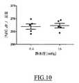
図10に移って、実験結果は、複数の異なる静水圧、すなわち、3mmHgおよび120mmHg(人体内で観察される一般的な範囲の体循環圧をカバーする)に関係する。 Turning to FIG. 10, the experimental results relate to a plurality of different hydrostatic pressures, namely 3 mmHg and 120 mmHg (covering the general range of systemic circulation pressures observed in the human body).
見てとれるように、種々の造影剤特性および静水圧について、特徴音圧ΓAPに有意な差はない。これは、本開示による技法が、造影剤特性のいずれの分散および患者内の実際の静水圧からも良好に独立していることを実証している。それゆえ、本技法は再現性、正確性およびロバスト性が高い。 As can be seen, there is no significant difference in feature sound pressure Γ AP for the various contrast agent properties and hydrostatic pressure. This demonstrates that the technique according to the present disclosure is well independent of any dispersion of contrast agent properties and the actual hydrostatic pressure in the patient. Therefore, the technique is highly reproducible, accurate and robust.
図11に移って、実験結果は、造影剤の複数の異なる濃度、すなわち、その標準値(0.3×106μm3/mL)、標準値の2分の1(0.15×106μm3/mL)、および標準値の2倍(0.6×106μm3/mL)に関係する。見てとれるように、特徴音圧ΓAPは、造影剤の濃度とともに増大する(造影剤が音響を減衰させるように作用し、その効果が造影剤の濃度とともに増大するため)。Turning to FIG. 11, the experimental results show that the contrast agent has a plurality of different concentrations, ie, its standard value (0.3 × 106 μm3 / mL), half of the standard value (0.15 × 10⁶). μm3 / mL), and related to twice the standard value(0.6 × 10 6 μm 3 / mL). As can be seen, the characteristic sound pressure Γ AP increases with the concentration of the contrast agent (because the contrast agent acts to attenuate the sound and its effect increases with the concentration of the contrast agent).
図12に移って、ここでは、同じ実験結果が、横軸上の造影剤の濃度に対して縦軸上に(相対)音響減衰(dB単位、造影剤の標準濃度についての特徴音圧ΓAPに対する)をプロットしているグラフにおいて示されている(誤差バーは、造影剤の各濃度値についての音響減衰の標準偏差を示す)。見てとれるように、音響減衰(dB単位)は、造影剤の濃度に比例し、特に、これらの実験結果の線形最適合は、決定係数R2=0.9996を有する。これによって、本開示による技法の、理論に対する非常に良好な一致が確認される。Turning to FIG. 12, here the same experimental results are shown relative to the concentration of contrast agent on the horizontal axis (relative) acoustic attenuation (in dB, for characteristic sound pressure Γ AP for standard concentrations of contrast agent) (The error bars show the standard deviation of the acoustic attenuation for each concentration value of the contrast agent). As can be seen, the acoustic attenuation (in dB) is proportional to the concentration of the contrast agent, in particular the linear optimum of these experimental results has a coefficient of determination R2 = 0.9996. This confirms a very good agreement with the theory of the techniques according to the present disclosure.
音響を減衰させるもの(上記で示したような)を一切なくして低調波応答を測定し、その後、音響を減衰させるように作用する2つのパッド(パッドP1およびパッドP2として参照される)を送信経路内に挿入することによってさらなる実験結果が収集された。特にパッドP1はPD442/1.6−ジイソシアネートヘキサン90.4/9.6%(質量)、50% アジピン酸ビス(2−エチルヘキシル)から構成され、9.5mmの厚さおよび38mmの直径を有しており、パッドP2はPD443/1.6−ジイソシアネートヘキサン90.5/9.5%(質量)、40% アジピン酸ビス(2−エチルヘキシル)から構成され、16mmの厚さおよび38mmの直径を有していた。低調波応答は、対応する特徴点の特徴音圧ΓAPを得るように、上述したモデル関数の対応するインスタンスによって適合された。 Measure the subharmonic response without any attenuating sound (as shown above) and then transmit two pads (referred to as pad P1 and pad P2) that act to attenuate the sound Further experimental results were collected by inserting into the pathway. In particular, the pad P1 is composed of 90.4 / 9.6% (by mass) PD442 / 1.6-diisocyanate hexane, 50% bis (2-ethylhexyl) adipate, and has a thickness of 9.5 mm and a diameter of 38 mm. The pad P2 is composed of PD 443 / 1.6-diisocyanate hexane 90.5 / 9.5% (by mass), 40% bis (2-ethylhexyl) adipate, and has a thickness of 16 mm and a diameter of 38 mm. I had it. The subharmonic response was adapted by the corresponding instance of the model function described above to obtain the feature sound pressure Γ AP of the corresponding feature point.
図13を参照すると、音響を減衰させるものが一切ない低調波応答(参照符号1305で示されている)、および、パッドP2を伴う低調波応答(参照符号1305pで示されている)が、横軸上の音圧(対数スケールでのkPa単位)に対して縦軸上に低調波レベル(dB単位)をプロットしているグラフにおいて示されている。見てとれるように、(送信経路において音響減衰が増大したため)低調波応答1305pの破壊部分が右向きにシフトしているが、低調波応答1305のパターンに対する大幅な歪みは一切ない(同様の考慮事項が、この図には示されていないパッドP1を伴う低調波応答に適用される)。これによって、低調波応答が音響減衰にかかわりなく実質的に一定のパターンを有することが確認される。 Referring to FIG. 13, the subharmonic response (indicated by reference numeral 1305) without any sound attenuation and the subharmonic response with pad P2 (indicated by reference numeral 1305p) are shown in the horizontal direction. Sub-harmonic levels (in dB) are plotted on the vertical axis against the on-axis sound pressure (in kPa in logarithmic scale) as shown in the graph. As can be seen, the breakdown portion of
対応する特徴音圧ΓAPと減衰させるものが一切ない特徴音圧ΓAPとの間の比(dB単位)として計算されるものとしての各パッドP1およびP2の音響減衰は、それぞれAtt1=2,42dBおよびAtt2=5.69dBであった。水中聴音器を使用した標準的な置換法によって測定される各パッドP1およびP2の実際の音響減衰は、Att1’=2.52dBおよびAtt2’=6.04dBであった。これによって、本開示による技法の精度が確認される。 The acoustic attenuation of each pad P1 and P2 as calculated as the ratio (in dB) between the corresponding feature sound pressure Γ AP and the feature sound pressure Γ AP without any attenuation is Att 1 = 2, 42 dB and Att2 = 5.69 dB. The actual acoustic attenuation of each pad P1 and P2 measured by the standard displacement method using hydrophones was Att1 '= 2.52 dB and Att2' = 6.04 dB. This confirms the accuracy of the techniques according to the present disclosure.
当然ながら、局所的なおよび特殊な要件を満たすために、当業者は、多くの論理的および/または物理的修正および改変を、本開示に適用してもよい。より詳細には、本開示はその1つまたは複数の実施形態に対する一定程度の特殊性をもって説明されているが、形態および詳細の様々な省略、置換および変更ならびに他の実施形態が可能であることが理解されるべきである。特に、本開示の異なる実施形態は、そのより完全な理解を提供するために先行する説明において記載されている特定の詳細(数値など)なしに実践することさえでき、反対に、不要な詳細で説明を曖昧にしないために、周知の特徴は省略または単純化されている場合がある。その上、本開示の任意の実施形態に関連して説明されている特定の要素および/または方法ステップは、一般的な設計選択の事項として任意の他の実施形態に組み込むことができることが明示的に意図されている。いずれにせよ、序数または他の修飾語句は、同じ名前を有する要素を区別するためのラベルとして使用されているに過ぎず、それ自体はいかなる優先度、先行性または順序を含意するものでもない。その上、含む(include)、備える(comprise)、有する(have)、包含する(contain)および伴う(involve)といった用語(ならびにそれらの任意の形態)は、オープンな、包括的でない意味(すなわち、列挙されている項目に限定されない)で意図されるべきであり、基づく(based on)、依存する(dependent on)、従う(according to)、応じる(function of)といった用語(ならびにそれらの任意の形態)は、非排他的な関係(すなわち、可能性のあるさらなる変化形が含まれる)として意図されるべきであり、(別段の指示がない限り)1つの(a/an)という用語は、1つまたは複数の項目として意図されるべきであり、手段(means for)という用語(または任意のミーンズプラスファンクション形式)は関連する機能を実行するのに適した任意の実体または構造として意図されるべきである。 Of course, many logical and / or physical modifications and alterations may be applied to the present disclosure to satisfy local and specific requirements. More particularly, although the present disclosure has been described with a degree of particularity to one or more of the embodiments, various omissions, substitutions and changes in the form and details, and other embodiments are possible. Should be understood. In particular, different embodiments of the present disclosure may even be practiced without the specific details (such as numerical values) set forth in the preceding description to provide a more thorough understanding thereof, and vice versa, with unnecessary details. Well-known features may be omitted or simplified in order not to obscure the description. Furthermore, it is explicitly stated that certain elements and / or method steps described in connection with any embodiment of the present disclosure may be incorporated into any other embodiment as a matter of general design choice. Intended for. In any case, ordinal numbers or other modifiers are only used as labels to distinguish elements having the same name, and as such do not imply any priority, precedence or order. Moreover, the terms include, comprise, comprise, have, contain and involve (as well as any form thereof) have an open, non-inclusive meaning (ie, The term should not be limited to the listed items) and should be based on, dependent on, according to, according to, function of, etc. (as well as any form thereof ) Should be intended as a non-exclusive relationship (ie including possible further variants), and (unless otherwise indicated) the term one (a / an) means 1 Should be intended as one or more items, means The term for) (or any means-plus-function form) should be intended as any entity or structure suitable to perform the associated function.
たとえば、一実施形態は、超音波スキャナとともに使用するための方法を提供する。方法は、以下のステップを含む。測定励起信号(超音波スキャナのパワーレベルを測定範囲内で変化させることによって生成される超音波を含む測定励起信号)が、超音波スキャナのトランスデューサによって患者の身体部分(方法を実施する前に患者に予め投与されている造影剤を含む患者)に印加される。測定応答(測定励起信号に応答して受信される測定エコー信号の非基本波成分のレベルを含む)が記録される。(測定応答に基づく)測定データと(基準応答に基づく)基準データとの間の比較に従って、推定値が決定される。推定値を決定する上記ステップは、以下の動作のうちの1つまたは複数を含む。基準応答が、較正エコー信号の上記非基本波成分のレベルを、造影剤を含むin−vitro較正構造内の音圧レベルの関数として表現する較正応答であるとき、(選択される目標音圧レベルを身体部分に印加するために必要とされる)目標パワーレベルおよび/または(選択されるさらなる目標音圧レベルが設定されているときに身体部分に印加される)さらなる目標音圧レベルが推定される。加えてまたは代替形態において、基準応答が、較正エコー信号の上記非基本波成分のレベルを、in−vitro較正構造内のパワーレベルの関数として表現するさらなる較正応答であるとき、(患者内でトランスデューサと身体部分との間で発生する)総音響減衰が推定される。加えてまたは代替形態において、基準応答が、さらなる測定エコー信号の上記非基本波成分のレベルを、さらなる身体部分内のパワーレベルの関数として表現するさらなる測定応答であるとき、(患者内で身体部分と患者のさらなる身体部分との間で発生する)部分音響減衰が推定される。 For example, one embodiment provides a method for use with an ultrasound scanner. The method comprises the following steps: The measurement excitation signal (measurement excitation signal including ultrasound generated by changing the power level of the ultrasound scanner within the measurement range) is transmitted to the patient's body part by the transducer of the ultrasound scanner (before performing the method) Applied to patients who have previously received a contrast agent. The measurement response (including the level of the non-fundamental component of the measurement echo signal received in response to the measurement excitation signal) is recorded. An estimate is determined according to the comparison between the measurement data (based on the measurement response) and the reference data (based on the reference response). The steps of determining an estimate include one or more of the following operations. When the reference response is a calibration response that represents the level of the non-fundamental component of the calibration echo signal as a function of the sound pressure level in the in-vitro calibration structure containing the contrast agent, The target power level required to apply the to the body part and / or the further target sound pressure level (applied to the body part when the additional target sound pressure level to be selected is set) is estimated Ru. In addition or in the alternative, when the reference response is a further calibration response representing the level of the non-fundamental component of the calibration echo signal as a function of the power level in the in-vitro calibration structure, Total acoustic attenuation that occurs between the and body parts is estimated. In addition or in the alternative, when the reference response is a further measurement response representing the level of the non-fundamental component of the further measurement echo signal as a function of the power level in the further body portion Partial acoustic attenuation is generated that occurs between the and the further body part of the patient.
しかしながら、本方法は、いずれの超音波スキャナとともに使用されてもよい(下記参照)。本方法は、いずれの身体部分に適用されてもよく、その全体のレベルにおいて適用されてもよく、その関心領域に適用されてもよく、または、身体部分の任意の位置(2Dまたは3D)または位置のグループについて個々に適用されてもよい。身体部分は、いずれの造影剤(たとえば、目標特異的なタイプの)を含んでもよい。測定励起信号は、いずれの様式で適用されてもよい(たとえば、各々が、一定のまたは増大/低減する任意の周波数、または、異なる周波数の混合を有する、任意の数の1つまたは複数のバーストから較正される、任意の形状および長さの超音波によって適用されてもよい)。超音波スキャナのパワーレベルはいずれの様式で規定されてもよい(たとえば、段階的なスケールの指標によって、または送信パワー又は送信電圧の実際の値によって、またはさらには、超音波スキャナによって生成される超音波の音圧の実際の値によって規定されてもよい)。その上、測定励起信号のパワーレベルは、いずれの非ゼロ範囲にわたっていずれの様式で変更されてもよい(たとえば、増大/低減する傾斜によって変更されてもよい)。測定応答は、いずれの様式で記録されてもよい(たとえば、エコー信号をアポダイズし、特に、矩形、余弦またはハニングタイプのような任意の種類の関数によってウィンドウイング/テーパリングすることによって記録されてもよい)。任意の非基本波成分のレベル(下記参照)は、いずれの様式で規定されてもよい(たとえば、エコー信号のパワーまたは振幅によって規定されてもよい)。基準応答はいずれのタイプのものであってもよく、測定データおよび基準データは、それぞれいずれの様式で測定応答および基準応答に基づいてもよく、推定値は、それらの間のいずれの比較に従って決定されてもよい(下記参照)。特に、基準応答は、音圧レベルの関数としてのみ規定されてもよく(いずれの様式で規定されてもよく、たとえば、任意の非ゼロ範囲にわたるそのエネルギーによって規定されてもよく)、パワーレベルの関数としてのみ規定されてもよく(いずれの非ゼロ範囲にわたって規定されてもよく、測定範囲と異なってさえいてもよい、いずれの様式で音圧レベルに対応してもよく、未知であってさえいてもよい)、または、それら両方の関数として規定されてもよい。較正構造およびさらなる身体部分は、いずれのタイプのものであってもよい(下記参照)。 However, the method may be used with any ultrasound scanner (see below). The method may be applied to any body part, may be applied at its whole level, may be applied to the area of interest, or any position (2D or 3D) or part of the body part It may be applied individually for groups of locations. The body part may contain any contrast agent (e.g. of target specific type). The measurement excitation signal may be applied in any manner (eg, any number of one or more bursts, each having any frequency that is constant or increasing / reducing, or a mixture of different frequencies) And may be applied by ultrasound of any shape and length). The power level of the ultrasound scanner may be defined in any manner (e.g. by means of a step scale indicator or by the actual value of the transmission power or the transmission voltage or even by the ultrasound scanner) It may be defined by the actual value of the sound pressure of the ultrasound). Moreover, the power level of the measurement excitation signal may be altered in any manner (eg, by increasing / decreasing slope) over any non-zero range. The measurement response may be recorded in any manner (e.g. by apodizing the echo signal, in particular by windowing / tapering with any kind of function such as rectangular, cosine or Hanning type) Also good). The level of any non-fundamental component (see below) may be defined in any manner (eg, by the power or amplitude of the echo signal). The reference response may be of any type, and the measurement data and the reference data may be based on the measurement response and the reference response, respectively, in any manner, and the estimates are determined according to any comparisons between them May be done (see below). In particular, the reference response may only be defined as a function of the sound pressure level (which may be defined in any manner, for example by its energy over any non-zero range), the power level of It may be defined only as a function (it may be defined over any non-zero range, may even differ from the measurement range, may correspond to the sound pressure level in any manner, or even unknown) Or as a function of both. The calibration structure and the further body part may be of any type (see below).
一実施形態において、推定値を判定する上記ステップは、超音波スキャナのパワーレベルと音圧レベルとの間の所定の関係にさらに従って目標パワーレベルおよび/またはさらなる目標音圧レベルを推定するステップを含む。 In one embodiment, the step of determining the estimate further comprises: estimating a target power level and / or a further target sound pressure level further according to a predetermined relationship between the power level and the sound pressure level of the ultrasound scanner. Including.
しかしながら、目標パワーレベルおよび/またはさらなる目標音圧レベルは、いずれの様式で推定されてもよい(下記参照)。 However, the target power level and / or the further target sound pressure level may be estimated in any manner (see below).
一実施形態において、本方法は、以下のステップをさらに含む。較正励起信号(超音波スキャナのパワーレベルを較正範囲内で変化させることによって生成される超音波を含む)が、トランスデューサによって較正構造に印加される。(較正励起信号に応答して受信される)較正エコー信号の上記非基本波成分のレベルが記録される。 In one embodiment, the method further comprises the following steps. A calibration excitation signal (including ultrasound generated by changing the power level of the ultrasound scanner within the calibration range) is applied by the transducer to the calibration structure. The level of the non-fundamental component of the calibration echo signal (received in response to the calibration excitation signal) is recorded.
しかしながら、いずれの較正構造(in−vitro)が(たとえば、既知の反射体によって)使用されてもよい。測定応答についてのものと同様の考慮事項が、較正励起信号の印加、および、較正応答の記録(ならびに、可能性として較正関数および較正点の決定)にも有効である。いずれにせよ、他の様式において較正データを提供するという可能性は除外されず、たとえば、一連の異なる動作条件(超音波スキャナの設定および/または造影剤のタイプなど)について較正データを(実験室内でまたはさらには分析的に)決定し、その後、この情報を超音波スキャナにロードすることが可能である。いずれにせよ、較正応答はまた、さらなる測定応答のみが使用されるときは省略されてもよい。 However, any calibration structure (in-vitro) may be used (e.g. by means of known reflectors). Similar considerations as for the measurement response apply to the application of the calibration excitation signal and to the recording of the calibration response (and possibly the determination of the calibration function and the calibration point). In any case, the possibility of providing calibration data in other ways is not excluded, for example, calibration data for a series of different operating conditions (such as ultrasound scanner settings and / or type of contrast agent) (in the laboratory) (Or even analytically) can be determined and then this information can be loaded into the ultrasound scanner. In any case, the calibration response may also be omitted when only the further measurement response is used.
一実施形態において、方法は、較正励起信号によって較正構造内の造影剤に印加される音圧レベルを測定するステップをさらに含む。 In one embodiment, the method further comprises the step of measuring the sound pressure level applied to the contrast agent in the calibration structure by the calibration excitation signal.
しかしながら、音圧レベルのみ、パワーレベルのみ、またはそれらの両方が測定されてもよい。 However, only sound pressure levels, only power levels, or both may be measured.
一実施形態において、較正構造内の造影剤は、較正励起信号および較正エコー信号の減衰を実質的にもたらさない閾値よりも低い濃度を有する。 In one embodiment, the contrast agent in the calibration structure has a concentration that is lower than a threshold value that results in substantially no attenuation of the calibration excitation signal and the calibration echo signal.
しかしながら、減衰は、最小値(たとえば、0.1〜1%)よりも低いときはゼロと考えられてもよい。いずれにせよ、較正応答はまた、異なる濃度の造影剤によって(及び減衰条件において)記録されてもよい。 However, the attenuation may be considered zero when below a minimum value (e.g. 0.1 to 1%). In any case, the calibration response may also be recorded by (and at attenuation conditions) different concentrations of contrast agent.
一実施形態において、本方法は、以下のステップをさらに含む。さらなる測定励起信号が、トランスデューサによってさらなる身体部分に印加される。(さらなる測定励起信号に応答して受信される)さらなる測定エコー信号の上記非基本波成分のレベルが記録される。 In one embodiment, the method further comprises the following steps. An additional measurement excitation signal is applied by the transducer to the further body part. The level of the non-fundamental component of the further measurement echo signal (received in response to the further measurement excitation signal) is recorded.
しかしながら、測定応答についてのものと同様の考慮事項が、さらなる測定励起信号の印加、および、さらなる測定応答の記録(ならびに、可能性としてさらなる測定関数およびさらなる測定点の決定)にも有効である。その上、さらなる測定応答は、いずれの数およびタイプのさらなる身体部分(たとえば、同じ臓器またはさらには異なる臓器内のいずれの深さにおける身体部分)からいずれの時点においても(同時にまたは測定応答とは別個に)記録することができる。いずれにせよ、さらなる測定応答はまた、較正応答のみが使用されるときは省略されてもよい。 However, considerations similar to those for the measurement response are also valid for the application of the further measurement excitation signal and for the recording of the further measurement response (and possibly the determination of the further measurement function and the further measurement point). Moreover, the additional measurement response may be from any number and type of additional body parts (e.g., body parts at any depth within the same organ or even different organs) at any time (simultaneously or with the measurement response). Can be recorded separately). In any case, the additional measurement response may also be omitted when only the calibration response is used.
一実施形態において、推定値を決定する上記ステップは、測定関数によって測定応答を適合させるステップと、測定関数と、基準応答を適合させる基準関数との間の比較に従って推定値を決定するステップとを含む。 In one embodiment, the step of determining the estimate comprises: fitting the measurement response with a measurement function; and determining the estimate according to a comparison between the measurement function and a reference function to which the reference response is fitted. Including.
しかしながら、測定応答は、いずれの既知の曲線適合アルゴリズムによる(たとえば、最小二乗、モーメントまたは最大尤度技法に基づく)測定関数によって適合されてもよい。測定関数は、いずれのタイプ(たとえば、シグモイドまたは累積対数正規関数)のものであってもよく、推測的に分かってさえいなくてもよい。測定関数および基準関数は、いずれの様式で比較されてもよい(下記参照)。いずれにせよ、測定応答を、基準関数または基準応答と直に(たとえいずれの測定関数も計算せずとも)比較するという可能性は原則的に(たとえば、測定応答の破壊部分と基準応答の破壊部分との間の差の平均に従って)除外されない。 However, the measurement response may be fitted by a measurement function (eg based on least squares, moments or maximum likelihood techniques) according to any known curve fitting algorithm. The measurement function may be of any type (eg, sigmoid or cumulative lognormal function), and may not even be known speculatively. The measurement function and the reference function may be compared in any manner (see below). In any case, the possibility of comparing the measured response directly with the reference function or the reference response (even without calculating any measured function) is in principle (for example, the destruction of the measured response and the destruction of the reference response) Not excluded) according to the average of the difference between parts.
一実施形態において、測定関数および基準関数は、全体的にS字形状を有するモデル関数のインスタンスであり、モデル関数は、実質的に一定の最後の値を有する最後の一定の区間と、実質的に一定のさらなる値を有するさらなる一定の区間と、さらなる一定の区間と最後の一定の区間との間の増大する区間とを含み、モデル関数はさらなる一定の値から最後の一定の値へと実質的に単調に増大する。 In one embodiment, the measurement function and the reference function are instances of a model function having a generally S-shaped shape, and the model function substantially corresponds to a last constant interval having a substantially constant last value. The model function includes a further constant interval with constant further values and an increasing interval between the further constant interval and the last constant interval, and the model function substantially reduces from the further constant value to the last constant value. Monotonously increases.
しかしながら、モデル関数の各区間は、いずれの非ゼロの長さを有してもよい。(最後の/さらなる)一定の区間は、いずれの一定の値を有してもよく、この値は、それらの変化が所定の閾値(たとえば、0.1〜1%)よりも低いときに実質的に一定であると考えることができ、その上、増大する区間は、いずれのタイプのものであってもよい(たとえば、いずれの数およびタイプの凹面を有して、厳密にまたは弱く増大してもよい)。いずれにせよ、異なる形状を有するモデル関数を使用することは除外されない。 However, each section of the model function may have any non-zero length. The (last / additional) constant interval may have any constant value, which value is substantially unchanged when their change is below a predetermined threshold (eg 0.1 to 1%). Can be considered to be constant, moreover, the increasing section may be of any type (eg, with any number and type of concaves, increasing strictly or weakly May). In any case, the use of model functions having different shapes is not excluded.
一実施形態において、モデル関数は、実質的に初期値を有する初期の一定の区間と、初期の一定の区間とさらなる一定の区間との間のさらなる増大する区間とをさらに含み、モデル関数が初期の一定の値からさらなる一定の値へと単調に増大する。 In one embodiment, the model function further includes an initial constant interval having a substantially initial value, and a further increasing interval between the initial constant interval and the further constant interval, and the model function is initial It monotonously increases from a constant value of to a further constant value.
しかしながら、上記と同様の考慮事項が、初期の一定の区間およびさらなる増大する区間にも適用される。いずれにせよ、モデル関数は、異なる、追加のまたは代替的な区間を含んでもよい。 However, the same considerations as above apply to the initial constant section and the further increasing section. In any case, the model function may include different, additional or alternative intervals.
より一般的に、モデル関数は、測定/基準応答の任意の他の部分(少なくとも、たとえば、遷移パワーレベルよりも上の、それらの破壊部分またはその相当部分を含む)に関係してもよく、たとえば、モデル関数は、上記で示したすべての区間から、増大する区間までのみに及んでもよい。 More generally, the model function may relate to any other part of the measurement / reference response (including at least, for example, their broken parts or their corresponding parts above the transition power level), For example, the model function may extend from all of the intervals shown above to only the increasing intervals.
一実施形態において、推定値を決定する上記ステップは、測定関数の増大する区間に特徴的である測定点を決定するステップと、測定点と、基準関数の増大する区間に特徴的である基準点との間の比較に従って推定値を決定するステップとを含む。 In one embodiment, the step of determining the estimated value comprises the steps of determining a measurement point that is characteristic of the increasing interval of the measurement function, a measurement point, and a reference point that is characteristic of the increasing interval of the reference function. Determining the estimated value according to the comparison between and.
しかしながら、測定点はいずれの様式で決定されてもよく(下記参照)、基準点は、基準音圧レベルのみによって、基準パワーレベルのみによって、または、それらの両方によって規定されてもよい。測定点および基準点は、いずれの様式で比較されてもよい(下記参照)。いずれにせよ、測定点を基準関数と、または、測定関数を基準関数と直に(たとえいずれの測定点も決定せずとも)比較するという可能性は原則的に(たとえば、測定関数および基準関数の増大する区間の間の差の平均に従って)除外されない。 However, the measurement points may be determined in any manner (see below) and the reference points may be defined by the reference sound pressure level only, by the reference power level only, or both. The measurement point and the reference point may be compared in any manner (see below). In any case, the possibility of comparing the measurement points directly with the reference function or the measurement function directly with the reference function (even without determining any measurement points) is in principle (for example, the measurement function and the reference function) Not according to the average of the differences between the increasing segments of
一実施形態において、推定値を決定する上記ステップは、測定関数のさらなる一定の区間と増大する区間との間の交差に対応する測定点を決定するステップと、測定点と、基準関数のさらなる一定の区間と増大する区間との間の交差に対応する基準点との間の比較に従って推定値を決定するステップとを含む。 In one embodiment, the step of determining the estimated value comprises the steps of determining a measuring point corresponding to the intersection between a further constant interval and an increasing interval of the measuring function, a measuring point and a further constant of the reference function. Determining the estimated value according to the comparison between the reference point corresponding to the intersection between the interval of and the increasing interval.
しかしながら、測定点/基準点は、いずれの他の様式において規定されてもよく、さらなる一定の区間と増大する区間との間の交差とは無関係でさえあってもよい(たとえば、増大する区間の一次導関数が1のような所定の値を有する点として規定されてもよい)。 However, the measurement point / reference point may be defined in any other manner, and may even be independent of the intersection between the further constant interval and the increasing interval (e.g. The first derivative may be defined as a point having a predetermined value such as 1).
一実施形態において、推定値を決定する上記ステップは、増大する区間の下降する垂直漸近線に対応する測定点を決定するステップと、測定点と、基準関数の増大する区間の下降する垂直漸近線に対応する基準点との間の比較に従って推定値を決定するステップとを含む。 In one embodiment, the step of determining the estimated value comprises the steps of determining a measurement point corresponding to the falling vertical asymptote of the increasing interval, the measuring point, and the falling vertical asymptote of the increasing interval of the reference function. Determining the estimated value according to the comparison between the reference point corresponding to.
しかしながら、測定点/基準点は、(たとえば、2つの区間が実際に交差する)さらなる一定の区間と増大する区間との間の交差に従った、いずれの他の様式において規定されてもよい。 However, measurement points / reference points may be defined in any other manner, according to the intersection between a further constant interval (e.g., where two intervals actually cross) and an increasing interval.
一実施形態において、基準点は、(較正応答を適合させる較正関数の増大する区間に特徴的である)較正点であり、目標パワーレベルおよび/またはさらなる目標音圧レベルを推定する上記ステップは、超音波スキャナのパワーレベルと音圧レベルとの間の所定の関係を、測定パワーレベル(測定点によって識別される)および較正音圧レベル(較正点によって識別される)に適用することによって、目標パワーレベルおよび/またはさらなる目標音圧レベルを推定するステップを含む。 In one embodiment, the reference point is a calibration point (characteristic of an increasing section of the calibration function to which the calibration response is fitted), and the above step of estimating the target power level and / or the further target sound pressure level is: The target by applying a predetermined relationship between the power level and the sound pressure level of the ultrasound scanner to the measured power level (identified by the measurement point) and the calibration sound pressure level (identified by the calibration point) Estimating the power level and / or the further target sound pressure level.
しかしながら、目標パワーレベルおよび/またはさらなる目標音圧レベルは、(分析的に知られるかまたは実験によって決定される、超音波スキャナの任意の関係に従って)任意の他の式によって計算されてもよい。 However, the target power level and / or the further target sound pressure level may be calculated by any other equation (according to any relationship of the ultrasonic scanner known analytically or determined by experiments).
一実施形態において、基準点は、さらなる較正応答を適合させるさらなる較正関数の増大する区間に特徴的であるさらなる較正点であり、総音響減衰を推定する上記ステップは、(測定点によって識別される)測定パワーレベルと(さらなる較正点によって識別される)較正パワーレベルとの間の比較に従って総音響減衰を推定するステップを含む。 In one embodiment, the reference point is a further calibration point that is characteristic of the increasing interval of the further calibration function to which the further calibration response is fitted, and the above step of estimating the total sound attenuation is identified by 2.) Estimating the total sound attenuation according to a comparison between the measured power level and the calibration power level (identified by the further calibration point).
しかしながら、総音響減衰は、測定パワーレベルと較正パワーレベルとの間のいずれの比較(たとえば、それらの差、比、さらには対数スケールにない)に従って計算されてもよく、いずれの様式において(たとえば、音圧の実際の損失を示すための絶対項において)表現されてもよい。 However, the total sound attenuation may be calculated according to any comparison between the measured power level and the calibration power level (e.g. not on their difference, ratio, or even logarithmic scale) and in any manner (e.g. , In absolute terms to indicate the actual loss of sound pressure).
一実施形態において、基準点は、さらなる測定応答を適合させるさらなる測定関数の増大する区間に特徴的であるさらなる測定点であり、部分音響減衰を推定する上記ステップは、(測定点によって識別される)測定パワーレベルと(さらなる測定点によって識別される)さらなる測定パワーレベルとの間の比較に従って部分音響減衰を推定するステップを含む。 In one embodiment, the reference point is a further measurement point that is characteristic of the increasing interval of the further measurement function to which the further measurement response is fitted, and the above step of estimating the partial acoustic attenuation is identified by 2.) Estimating the partial acoustic attenuation according to a comparison between the measured power level and the further measured power level (identified by the further measurement point).
しかしながら部分音響減衰は、2つの測定パワーレベル間のいずれの比較に従って計算されてもよく、上記のようにいずれの様式で表現されてもよい。 However, partial acoustic attenuation may be calculated according to any comparison between the two measured power levels and may be expressed in any manner as described above.
一実施形態において、身体部分およびさらなる身体部分は、患者内でその皮膚から異なる深さにある。 In one embodiment, the body part and the further body part are at different depths from the skin in the patient.
しかしながら、2つの身体部分はいずれの異なる深さにあってもよく、いずれにせよ、異なる臓器の間の(たとえ同じ深さにおいても)部分音響減衰の推定は除外されない。 However, the two body parts may be at any different depth, and in any case the estimation of partial acoustic attenuation between different organs (even at the same depth) is not ruled out.
一実施形態において、上記非基本波成分は、エコー信号の低調波成分である。 In one embodiment, the non-fundamental component is a subharmonic component of the echo signal.
しかしながら、異なる、代替的なまたは追加の非基本波成分(またはそれらの任意の組み合わせ)の使用は除外されず、たとえば、より高い高調波成分(2次または3次高調波など)または超高調波成分(基本周波数の1.5または2.5倍に等しい周波数を有するものなど)を使用することを妨げるものはない。 However, the use of different, alternative or additional non-fundamental components (or any combination thereof) is not excluded, for example, higher harmonic components (such as second or third harmonic) or hyperharmonics Nothing prevents the use of components (such as those having a frequency equal to 1.5 or 2.5 times the fundamental frequency).
一実施形態において、上記低調波成分は、エコー信号の基本周波数の1/2に等しい。 In one embodiment, the subharmonic component is equal to one half of the fundamental frequency of the echo signal.
しかしながら、任意の異なる、代替的なまたは追加の低調波成分(またはそれらの任意の組み合わせ)の使用は除外されない(たとえば、基本周波数の1/3または1/4に等しい低調波成分)。 However, the use of any different, alternative or additional subharmonic components (or any combination thereof) is not excluded (e.g. subharmonic components equal to 1/3 or 1/4 of the fundamental frequency).
一実施形態において、測定励起信号を印加する上記ステップは、第1の測定励起信号、および、第1の測定励起信号と反対の第2の測定励起信号を印加するステップを含み、測定応答を記録する上記ステップは、第1の測定励起信号に応答した第1の測定応答および第2の測定励起信号に応答した第2の測定応答を記録するステップと、第1の測定応答および第2の測定応答の組み合わせに従って測定応答を得るステップとを含む。 In one embodiment, applying the measurement excitation signal comprises applying a first measurement excitation signal and a second measurement excitation signal opposite to the first measurement excitation signal and recording the measurement response And recording the first measurement response in response to the first measurement excitation signal and the second measurement response in response to the second measurement excitation signal, the first measurement response and the second measurement. Obtaining a measurement response according to the combination of responses.
しかしながら、測定応答は、いずれのマルチパルス励起技法を用いて得られてもよい。特に、測定励起信号は、いずれのタイプ(たとえば、異なる振幅を有する)のものであってもよく、いずれの様式で(たとえば、連続的にまたは交互的に)印加されてもよく、その上、対応する測定応答は、いずれの様式で(たとえば、直接的にまたは対応する重みを付けて、それらを加算または減算することによって)組み合わされてもよい。いずれにせよ、単一パルス励起技法に基づく基本実施態様(すなわち、超音波パルスの単一バーストから構成される測定励起信号による)は除外されない。 However, the measurement response may be obtained using any multi-pulse excitation technique. In particular, the measurement excitation signal may be of any type (e.g. having a different amplitude) and may be applied in any manner (e.g. continuously or alternately), as well as The corresponding measurement responses may be combined in any manner (e.g., directly or with corresponding weights and adding or subtracting them). In any case, basic implementations based on single pulse excitation techniques (i.e. with a measurement excitation signal consisting of a single burst of ultrasound pulses) are not excluded.
一実施形態において、本方法は、目標パワーレベルに従って超音波スキャナを制御するステップをさらに含む。 In one embodiment, the method further comprises controlling the ultrasound scanner according to the target power level.
しかしながら、単純化された実施態様において、目標パワーレベルは単純に、それに従ってマニュアル式で超音波スキャナを設定する操作者に表示されてもよい。 However, in a simplified embodiment, the target power level may simply be displayed to an operator who manually configures the ultrasound scanner accordingly.
一般的に、均等な方法を用いて(より多くのステップもしくはその一部の同じ機能を有する同様のステップを使用すること、不必要であるいくつかのステップを除去すること、または、さらなる任意選択のステップを追加することによって)同じソリューションが実施される場合に、同様の考慮事項が適用され、その上、それらのステップは、(少なくとも部分的に)異なる順序で、同時にまたは交互的に実施されてもよい。 In general, using an equivalent method (using more steps or similar steps with the same function as part of it, removing some steps that are unnecessary, or further options The same considerations apply if the same solution is carried out by adding the steps of (a), moreover, those steps are carried out simultaneously or alternately in a different order (at least in part) May be
いずれにせよ、上述した方法は、患者(および、特に、本方法を実施する前に患者に予め投与され得る造影剤)との一切の相互作用から独立して実施することができるデータ処理(または計算)方法であることが強調される。その上、造影剤はまた、非侵襲的に(たとえば、消化管を撮像するために経口で、もしくは、気道へと噴霧器によって)患者に投与することもでき、または、いずれの事例においても、専門的な医学知識を必要とするか、もしくは、患者に対する何らかの健康危機を伴うことになる、患者に対する一切の実質的な物理的介入(例えば、筋肉注射)なしに投与することもできる。いずれにせよ、提案されている方法は医師の職務を容易にすることができるが、本方法は一般的に、(たとえ治療目的の処置および/または治療目的の診断の判断が厳密な意味で常に医師自身によって行われるとしても)医師が、治療適用において身体部分の処置を制御すること、および/または、診断適用において身体部分を分析することを助けることができる中間結果を提供するにすぎない。 In any case, the method described above can be performed data processing (or can be performed independently of any interaction with the patient (and, in particular, the contrast agent that can be pre-administered to the patient prior to performing the method) It is emphasized that it is a calculation method. Moreover, the contrast agent can also be administered to the patient non-invasively (e.g. orally to image the digestive tract or by means of a sprayer into the airway) or in any case specialized It may also be administered without any substantial physical intervention (e.g., intramuscular injection) on the patient, which may require significant medical knowledge or involve any health crisis on the patient. In any case, although the proposed method can facilitate the work of the physician, the method is generally (even if treatment decisions for therapeutic purposes and / or diagnostic decisions for therapeutic purposes are always strict) It only provides intermediate results that can help the physician control the treatment of the body part in a therapeutic application and / or analyze the body part in a diagnostic application, even if performed by the physician himself.
さらなる実施形態は、コンピュータプログラムを提供し、コンピュータプログラムは、コンピュータプログラムがコンピュータシステム上で実行されると、コンピュータシステムに、上述した方法を実施させるように構成されている。 A further embodiment provides a computer program, wherein the computer program is configured to cause the computer system to perform the method described above when the computer program is run on a computer system.
さらなる実施形態は、コンピュータプログラム製品を提供し、コンピュータプログラム製品は、コンピュータプログラムを具現化するコンピュータ読み取り可能記憶媒体を備え、コンピュータプログラムは、コンピュータシステムの作業メモリにロード可能であり、それによって、コンピュータシステムが、同方法を実施するように構成する。 A further embodiment provides a computer program product, the computer program product comprising a computer readable storage medium embodying a computer program, the computer program being loadable into a working memory of a computer system, whereby the computer is The system is configured to perform the same method.
しかしながら、同じソリューションが独立型モジュールとして、超音波スキャナの制御プログラムのためのプラグインとして、またはさらには、制御プログラム自体の中に直に実装されてもよく、同じソリューションを、ネットワーク(インターネットなど)を通じてアクセスされるサービスとして展開することも可能であることは容易に明らかにされる。いずれにせよ、(本開示の各実施形態を実装するために使用することができる)ソフトウェアプログラムが別様に構成される場合、または、追加のモジュールもしくは機能が提供される場合に、同様の考慮事項が適用され、同様に、メモリ構造は他のタイプのものであってもよく、もしくは、均等な実体(必ずしも物理的な記憶媒体から構成されるとは限らない)と置き換えられてもよい。プログラムは、(たとえば、仮想機械内で)任意のデータ処理もしくはコンピュータシステムによって、または、それらと接続して使用されるのに適したいずれの形態をとってもよく、それによって、所望の動作を実施するようにシステムを構成し、特に、プログラムは、外部または常駐ソフトウェア、ファームウェア、またはマイクロコード(たとえば、コンパイルまたは解釈されるべきオブジェクトコードまたはソースコードのマイクロコード)の形態であってもよい。その上、プログラムを任意のコンピュータ使用可能媒体上で(特に、非一時的媒体上の製造品として)提供することが可能であり、媒体は、プログラムを収容、記憶、通信、伝搬、または転送するのに適した任意の要素であってもよい。たとえば、媒体は、電子、磁気、光学、電磁、赤外線、または半導体のタイプのものであってもよく、そのような媒体の例は、(プログラムを予めロードすることができる)固定ディスク、リムーバブルディスク、テープ、カード、ワイヤ、ファイバ、ワイヤレス接続、ネットワーク、放送波などである。いずれにせよ、本発明の一実施形態によるソリューションは、ハードウェア構造(たとえば、半導体材料チップ内に集積されている)を用いてさえ、または、適切にプログラムもしくは他の様態で構成されているソフトウェアとハードウェアとの組み合わせを用いてそれ自体を実装されるようにする。 However, the same solution may be implemented directly as a stand-alone module, as a plug-in for the control program of the ultrasound scanner, or even directly in the control program itself, the same solution, network (such as the Internet) It is readily apparent that it is also possible to deploy as a service accessed through. In any case, similar considerations, if the software program (which can be used to implement each embodiment of the present disclosure) is otherwise configured, or if additional modules or functions are provided. The matter applies, and likewise, the memory structure may be of another type or be replaced by an equivalent entity (not necessarily consisting of a physical storage medium). The program may take any form suitable for being used by or in connection with any data processing or computer system (e.g. in a virtual machine), thereby performing the desired operation In particular, the program may be in the form of external or resident software, firmware or microcode (e.g. microcode of object code or source code to be compiled or interpreted). Moreover, the program can be provided on any computer usable medium (in particular as an article of manufacture on a non-transitory medium), which medium houses, stores, communicates, propagates or transfers the program. It may be any element suitable for For example, the medium may be of the electronic, magnetic, optical, electromagnetic, infrared, or semiconductor type, and examples of such a medium are fixed disks (which can be preloaded with programs) fixed disks, removable disks , Tapes, cards, wires, fibers, wireless connections, networks, broadcast waves, etc. In any case, the solution according to an embodiment of the present invention is software that is even configured using a hardware structure (e.g. integrated in a semiconductor material chip) or suitably programmed or otherwise Let itself be implemented using a combination of and hardware.
さらなる実施形態は、上述した方法のステップを実施するように構成されている手段を備えるシステムを提供する。 A further embodiment provides a system comprising means configured to perform the steps of the method described above.
しかしながら、超音波スキャナは、いずれのタイプ(たとえば、線形、凸状またはフェーズドタイプのトランスデューサを有する)のものであってもよい。その上、同じソリューションが、超音波スキャナおよび個別のコンピュータ(または任意の均等なシステム)を備えるシステムにおいて適用されてもよく、この事例において、記録されている情報は、その処理のために(たとえば、デジタル、アナログまたはネットワーク接続を通じて)超音波スキャナからコンピュータに転送される。 However, the ultrasound scanner may be of any type (e.g. with linear, convex or phased type transducers). Moreover, the same solution may be applied in a system comprising an ultrasound scanner and a separate computer (or any equivalent system), in this case the information being recorded for its processing (e.g. Transferred from the ultrasound scanner to the computer (via digital, analog or network connection).
一般的に、システムが異なる構造を有するかもしくは均等な構成要素を備える場合、または、システムが他の動作特性を有する場合に、同様の考慮事項が適用される。いずれにせよ、そのすべての構成要素は、より多くの要素に分離されてもよく、または、2つ以上の構成要素が単一の要素に組み合わされてもよく、その上、各構成要素は、対応する動作を並列して実行することをサポートするために、複製されてもよい。その上、別途指定されない限り、異なる構成要素間のいずれかの相互作用は連続的である必要はなく、直接的なものであってもよく、または、1つもしくは複数の媒介を通じた間接的なものであってもよい。 In general, similar considerations apply if the system has a different structure or has equal components, or if the system has other operating characteristics. In any case, all its components may be separated into more elements, or two or more components may be combined into a single element, moreover, each component may be It may be replicated to support parallel execution of the corresponding operations. Moreover, unless otherwise specified, any interaction between different components need not be continuous, and may be direct, or indirectly through one or more mediators It may be one.
さらなる実施形態は、以下のステップを含む治療方法を提供する。造影剤が患者の身体を灌流するようにするために、造影剤が患者に投与される。超音波スキャナのパワーレベルを測定範囲内で変化させることによって生成される超音波を含む測定励起信号が、超音波スキャナのトランスデューサによって身体部分に印加される。測定励起信号に応答して受信される測定エコー信号の非基本波成分のレベルを含む測定応答が記録される(測定応答は、選択される目標音圧レベルを身体部分に印加するために必要とされる上記目標パワーレベルを推定するために、上述した方法に従って処理される)。上記目標パワーレベルに従って超音波スキャナのパワーレベルを設定することによって生成されるさらなる超音波が、身体部分に印加される。 A further embodiment provides a method of treatment comprising the following steps. The contrast agent is administered to the patient in order to cause the contrast agent to perfuse the patient's body. A measurement excitation signal comprising ultrasound generated by changing the power level of the ultrasound scanner within the measurement range is applied to the body part by the transducer of the ultrasound scanner. A measurement response is recorded that includes the level of the non-fundamental component of the measurement echo signal received in response to the measurement excitation signal (the measurement response is necessary to apply the selected target sound pressure level to the body part Process according to the method described above to estimate the target power level being Additional ultrasound waves, generated by setting the power level of the ultrasound scanner according to the target power level, are applied to the body part.
しかしながら、得られた情報はいずれの様式で使用されてもよい。たとえば、造影剤を、身体部分を加熱するための熱蓄積の目標として使用することが可能であり、その上、薬剤で機能化されている造影剤を使用し、その粒子を破壊して薬剤がin−situで送達されるようにすることが可能である(測定応答が、機能化されていない同じ造影剤を使用して記録される)。同方法は、いずれの種類の治療適用(この用語の広範な意味における治療適用、たとえば、病的状態を治療すること、その進行を回避すること、病的状態の発生を防止すること、または、単純に患者の快適度を改善することを目的とするもの)、および、任意の(ヒトまたは動物の)患者のいずれの種類の身体部分(たとえば、肝臓、前立腺または心臓のような臓器、領域または組織)の処置にも適用することができる。 However, the information obtained may be used in any manner. For example, it is possible to use a contrast agent as a heat accumulation target to heat the body part, and additionally use a drug-functionalized contrast agent to destroy its particles and It is possible to be delivered in-situ (the measurement response is recorded using the same non-functionalized contrast agent). The method may be applied to any type of therapeutic application (therapeutic application in the broad sense of this term, eg treating a pathological condition, avoiding its progression, preventing the occurrence of a pathological condition, or Simply for the purpose of improving the comfort of the patient) and any type of body part of the patient (of human or animal) (for example organs such as liver, prostate or heart, area or Tissue treatment).
さらなる実施形態は、以下のステップを含む診断方法を提供する。造影剤が患者の身体部分を灌流するようにするために、造影剤が患者に投与される。超音波スキャナのパワーレベルを測定範囲内で変化させることによって生成される超音波を含む測定励起信号が、超音波スキャナのトランスデューサによって身体部分に印加される。測定励起信号に応答して受信される測定エコー信号の非基本波成分のレベルを含む測定応答が記録される(測定応答は、患者内でトランスデューサと身体部分との間で発生する上記総音響減衰、および/または、患者内で患者の身体部分とさらなる身体部分との間で発生する上記部分音響減衰を推定するために、上述した方法に従って処理される)。身体部分の健康状態が、総音響減衰および/または部分音響減衰に従って評価される。 A further embodiment provides a diagnostic method comprising the following steps. The contrast agent is administered to the patient in order to cause the contrast agent to perfuse the body part of the patient. A measurement excitation signal comprising ultrasound generated by changing the power level of the ultrasound scanner within the measurement range is applied to the body part by the transducer of the ultrasound scanner. A measurement response is recorded that includes the level of the non-fundamental component of the measurement echo signal received in response to the measurement excitation signal (the measurement response is the total acoustic attenuation generated between the transducer and the body part in the patient) And / or processed according to the method described above in order to estimate the above-mentioned partial acoustic attenuation occurring between the patient's body part and the further body part in the patient). The health status of the body part is assessed according to the total and / or partial acoustic attenuation.
しかしながら、得られた情報はいずれの様式で(たとえば、身体部分の各位置、または、隣接する位置のグループの(総/部分)音響減衰を推定し、その後、その各ピクセル値が、対応する位置の音響減衰を表すパラメトリック画像を生成することによって)使用されてもよい。同方法は、いずれの種類の診断適用(この用語の広範な意味における診断適用、たとえば、新たな病変を発見することまたは既知の病変をモニタリングすることを目的とするもの)、および、任意の患者のいずれの種類の身体部分(上記参照)の分析にも応用することができる。 However, the information obtained estimates the (total / partial) acoustic attenuation of each position of the body part or groups of adjacent positions in any manner, for example, after which each pixel value corresponds to the corresponding position. May be used by generating a parametric image that represents the acoustic attenuation of The method is applicable to any type of diagnostic application (diagnostic application in the broad sense of this term, eg, for the purpose of finding new lesions or monitoring known lesions), and any patient It can be applied to the analysis of any kind of body part (see above).
Claims (23)
Translated fromJapanese前記超音波スキャナのパワーレベルを測定範囲内で変化させることによって生成される超音波を含む測定励起信号を、前記超音波スキャナのトランスデューサによって前記方法を実施する前に患者に予め投与されている造影剤を含む前記患者の身体部分に印加するステップ(A7)と、
前記測定励起信号に応答して受信される測定エコー信号の非基本波成分のレベルを含む測定応答を記録するステップ(A8)と、
前記測定応答に基づく測定データと基準応答に基づく基準データとの間の比較に従って、推定値を決定するステップ(A9〜A14)と、
を含み、
前記推定値を決定するステップは、
a)前記基準応答が、較正エコー信号の前記非基本波成分のレベルを、前記造影剤を含むin−vitro較正構造内の音圧レベルの関数として表現する較正応答であるとき、選択される目標音圧レベルを前記身体部分に印加するために必要とされる目標パワーレベルおよび/または選択されるさらなる目標音圧レベルが設定されているときに前記身体部分に印加されるさらなる目標音圧レベルを推定するステップ(A11)と、
b)前記基準応答が、前記較正エコー信号の前記非基本波成分のレベルを、前記in−vitro較正構造内の前記パワーレベルの関数として表現するさらなる較正応答であるとき、前記患者内で前記トランスデューサと前記身体部分との間で発生する総音響減衰を推定するステップ(A13)と、
c)前記基準応答が、さらなる測定エコー信号の前記非基本波成分のレベルを、前記患者のさらなる身体部分内の前記パワーレベルの関数として表現するさらなる測定応答であるとき、前記患者内で前記身体部分と前記さらなる身体部分との間で発生する部分音響減衰を推定するステップ(A14)と、
を含む、方法(A1〜A15)。A method (A1-A15) for use with an ultrasound scanner, wherein
A measurement excitation signal comprising ultrasound generated by varying the power level of the ultrasound scanner within the measurement range is pre-administered to the patient prior to performing the method by the transducer of the ultrasound scanner Applying (A7) to the body part of said patient containing the agent;
Recording (A8) a measurement response including levels of non-fundamental components of the measurement echo signal received in response to the measurement excitation signal;
Determining an estimated value (A9 to A14) according to a comparison between measurement data based on said measurement response and reference data based on a reference response;
Including
The step of determining the estimated value comprises
a) The target selected when the reference response is a calibration response representing the level of the non-fundamental component of the calibration echo signal as a function of the sound pressure level in the in-vitro calibration structure comprising the contrast agent The target power level required to apply a sound pressure level to the body part and / or the additional target sound pressure level to be applied to the body part when a further target sound pressure level to be selected is set Estimating (A11),
b) the transducer in the patient when the reference response is a further calibration response that represents the level of the non-fundamental component of the calibration echo signal as a function of the power level in the in-vitro calibration structure Estimating the total sound attenuation occurring between the and the body part (A13),
c) the body in the patient when the reference response is a further measurement response representing the level of the non-fundamental component of the further measurement echo signal as a function of the power level in the further body part of the patient Estimating (A14) partial acoustic attenuation occurring between the part and the further body part;
A method (A1 to A15).
前記超音波スキャナの前記パワーレベルと前記音圧レベルとの間の所定の関係にさらに従って前記目標パワーレベルおよび/または前記さらなる目標音圧レベルを推定するステップ(A11)を含む、請求項1に記載の方法(A1〜A15)。The step of determining the estimated value (A9 to A14) includes
The method according to claim 1, further comprising the step (A11) of estimating the target power level and / or the further target sound pressure level further according to a predetermined relationship between the power level and the sound pressure level of the ultrasound scanner. The described method (A1 to A15).
前記較正励起信号に応答して受信される前記較正エコー信号の前記非基本波成分のレベルを記録するステップ(A2)と、
をさらに含む、請求項1または請求項2に記載の方法(A1〜A15)。Applying (A1) a calibration excitation signal comprising ultrasound generated by varying the power level of the ultrasound scanner within a calibration range to the calibration structure by the transducer;
Recording the level of the non-fundamental component of the calibration echo signal received in response to the calibration excitation signal (A2);
The method (A1 to A15) according to claim 1 or claim 2, further comprising
前記さらなる測定励起信号に応答して受信される前記さらなる測定エコー信号の前記非基本波成分のレベルを記録するステップ(A8)と、
をさらに含む、請求項1から請求項5のいずれか一項に記載の方法(A1〜A15)。Applying the further measured excitation signal to the further body part by the transducer (A7);
Recording the level of the non-fundamental component of the further measurement echo signal received in response to the further measurement excitation signal (A8);
The method (A1 to A15) according to any one of claims 1 to 5, further comprising
前記測定応答を測定関数によって適合させるステップ(A9)と、
前記測定関数と、前記基準応答を適合させる基準関数との間の比較に従って、前記推定値を決定するステップ(A10〜A14)と、
を含む、請求項1から請求項6のいずれか一項に記載の方法(A1〜A15)。The step of determining the estimated value (A9 to A14) includes
Fitting the measurement response according to a measurement function (A9)
Determining the estimated value according to a comparison between the measurement function and a reference function to which the reference response is fitted (A10 to A14);
The method (A1 to A15) according to any one of claims 1 to 6, comprising
前記測定関数の前記増大する区間に特徴的である測定点を決定するステップ(A10)と、
前記測定点と、前記基準関数の前記増大する区間に特徴的である基準点との間の比較に従って、前記推定値を決定するステップ(A11〜A14)と、
を含む、請求項8または請求項9に記載の方法(A1〜A15)。The step of determining the estimated value (A9 to A14) includes
Determining a measurement point that is characteristic of the increasing interval of the measurement function (A10);
Determining the estimated value according to a comparison between the measuring point and a reference point characteristic of the increasing section of the reference function (A11 to A14);
The method (A1 to A15) according to claim 8 or 9, comprising
前記測定関数の前記さらなる一定の区間と前記増大する区間との間の交差に対応する測定点を決定するステップ(A10)と、
前記測定点と、前記基準関数の前記さらなる一定の区間と前記増大する区間との間の交差に対応する前記基準点との間の比較に従って、前記推定値を決定するステップ(A11〜A14)と、
を含む、請求項10に記載の方法(A1〜A15)。The step of determining the estimated value (A9 to A14) includes
Determining (A10) a measurement point corresponding to the intersection between the further constant interval of the measurement function and the increasing interval;
Determining the estimated value according to a comparison between the measuring point and the reference point corresponding to the intersection between the further constant section of the reference function and the increasing section (A11 to A14) ,
The method according to claim 10, comprising (A1 to A15).
前記測定関数の前記増大する区間の下降する垂直漸近線に対応する測定点を決定するステップ(A10)と、
前記測定点と、前記基準関数の前記増大する区間の下降する垂直漸近線に対応する前記基準点との間の比較に従って前記推定値を決定するステップ(A11〜A14)と、
を含む、請求項11に記載の方法(A1〜A15)。The step of determining the estimated value (A9 to A14) includes
Determining (A10) a measurement point corresponding to the descending vertical asymptote of the increasing section of the measurement function;
Determining the estimated value according to a comparison between the measurement point and the reference point corresponding to the descending vertical asymptote of the increasing section of the reference function (A11 to A14);
The method according to claim 11, comprising (A1 to A15).
前記目標パワーレベルおよび/または前記さらなる目標音圧レベルを推定するステップ(A11)は、前記超音波スキャナの前記パワーレベルと前記音圧レベルとの間の所定の関係を、前記測定点によって識別される測定パワーレベルおよび前記較正点によって識別される較正音圧レベルに適用することによって、前記目標パワーレベルおよび/または前記さらなる目標音圧レベルを推定するステップ(A11)を含む、
請求項2に直接的または間接的に従属するときの、請求項10から請求項12のいずれか一項に記載の方法(A1〜A15)。The reference point is a calibration point that is characteristic of the increasing interval of a calibration function to which the calibration response is fitted;
The step (A11) of estimating the target power level and / or the further target sound pressure level identifies a predetermined relationship between the power level of the ultrasound scanner and the sound pressure level by the measurement point. Estimating (A11) the target power level and / or the further target sound pressure level by applying to the measured power level and the calibration sound pressure level identified by the calibration point
The method (A1 to A15) according to any one of claims 10 to 12, when directly or indirectly dependent on claim 2.
前記総音響減衰を推定するステップ(A13)は、前記測定点によって識別される測定パワーレベルと前記さらなる較正点によって識別される較正パワーレベルとの間の比較に従って前記総音響減衰を推定するステップ(A13)を含む、
請求項10から請求項12のいずれか一項に記載の方法(A1〜A15)。The reference point is a further calibration point that is characteristic of the increasing interval of a further calibration function to which a further calibration response is fitted,
The step of estimating the total sound attenuation (A13) estimates the total sound attenuation according to a comparison between the measured power level identified by the measurement point and the calibration power level identified by the further calibration point (A13). Including A13),
The method (A1 to A15) according to any one of claims 10 to 12.
前記部分音響減衰を推定するステップ(A14)は、前記測定点によって識別される測定パワーレベルと前記さらなる測定点によって識別されるさらなる測定パワーレベルとの間の比較に従って前記部分音響減衰を推定するステップ(A14)を含む、
請求項10から請求項14のいずれか一項に記載の方法(A1〜A15)。The reference point is a further measurement point that is characteristic of the increasing interval of a further measurement function to which the further measurement response is adapted,
The step of estimating the partial acoustic attenuation (A14) estimates the partial acoustic attenuation according to a comparison between a measured power level identified by the measurement point and a further measured power level identified by the further measurement point. Including (A14),
The method (A1-A15) as described in any one of Claims 10-14.
第1の測定励起信号、および、前記第1の測定励起信号に反対の第2の測定励起信号を印加するステップ(A7)を含み、
前記測定応答を記録するステップ(A8)は、
前記第1の測定励起信号に応答した第1の測定応答および前記第2の測定励起信号に応答した第2の測定応答を記録するステップ(A8)と、
前記第1の測定応答および前記第2の測定応答の組み合わせに従って前記測定応答を得るステップと、を含む、
請求項1から請求項18のいずれか一項に記載の方法(A1〜A15)。In the step (A7) of applying the measurement excitation signal,
Applying a first measured excitation signal and a second measured excitation signal opposite to the first measured excitation signal (A7),
In the step (A8) of recording the measurement response,
Recording a first measurement response in response to the first measurement excitation signal and a second measurement response in response to the second measurement excitation signal (A8);
Obtaining the measurement response according to a combination of the first measurement response and the second measurement response.
The method (A1 to A15) according to any one of claims 1 to 18.
前記方法は、
前記超音波スキャナのパワーレベルを測定範囲内で変化させることによって生成される超音波を含む測定励起信号を、前記超音波スキャナのトランスデューサによって前記方法を実施する前に患者に予め投与されている造影剤を含む前記患者の身体部分に印加するステップと、
前記測定励起信号に応答して受信される測定エコー信号の非基本波成分のレベルを含む測定応答を記録するステップと、
前記測定応答に基づく測定データと基準応答に基づく基準データとの間の比較に従って、推定値を決定するステップと、
を含み、
前記推定値を決定するステップは、
a)前記基準応答が、較正エコー信号の前記非基本波成分のレベルを、前記造影剤を含むin−vitro較正構造内の音圧レベルの関数として表現する較正応答であるとき、選択される目標音圧レベルを前記身体部分に印加するために必要とされる目標パワーレベルおよび/または選択されるさらなる目標音圧レベルが設定されているときに前記身体部分に印加されるさらなる目標音圧レベルを推定するステップと、
b)前記基準応答が、前記較正エコー信号の前記非基本波成分のレベルを、前記in−vitro較正構造内の前記パワーレベルの関数として表現するさらなる較正応答であるとき、前記患者内で前記トランスデューサと前記身体部分との間で発生する総音響減衰を推定するステップと、
c)前記基準応答が、さらなる測定エコー信号の前記非基本波成分のレベルを、前記患者のさらなる身体部分内の前記パワーレベルの関数として表現するさらなる測定応答であるとき、前記患者内で前記身体部分と前記さらなる身体部分との間で発生する部分音響減衰を推定するステップと、
を含む、コンピュータプログラム製品。A computer program product comprising a computer readable storage medium embodying a computer program, said computer program being loadable into a working memory of a computer system, whereby using said computer system with an ultrasound scanner To implement the method for
The method is
A measurement excitation signal comprising ultrasound generated by varying the power level of the ultrasound scanner within the measurement range is pre-administered to the patient prior to performing the method by the transducer of the ultrasound scanner Applying to the body part of the patient containing the agent;
Recording a measurement response including levels of non-fundamental components of the measurement echo signal received in response to the measurement excitation signal;
Determining an estimated value according to a comparison between measured data based on said measured response and reference data based on a reference response;
Including
The step of determining the estimated value comprises
a) The target selected when the reference response is a calibration response representing the level of the non-fundamental component of the calibration echo signal as a function of the sound pressure level in the in-vitro calibration structure comprising the contrast agent The target power level required to apply a sound pressure level to the body part and / or the additional target sound pressure level to be applied to the body part when a further target sound pressure level to be selected is set Estimating steps;
b) the transducer in the patient when the reference response is a further calibration response that represents the level of the non-fundamental component of the calibration echo signal as a function of the power level in the in-vitro calibration structure Estimating the total sound attenuation occurring between the and the body part;
c) the body in the patient when the reference response is a further measurement response representing the level of the non-fundamental component of the further measurement echo signal as a function of the power level in the further body part of the patient Estimating the partial acoustic attenuation occurring between the part and the further body part;
Computer program products, including:
Applications Claiming Priority (3)
| Application Number | Priority Date | Filing Date | Title |
|---|---|---|---|
| EP14163716.5 | 2014-04-07 | ||
| EP14163716 | 2014-04-07 | ||
| PCT/EP2015/097020WO2015155380A1 (en) | 2014-04-07 | 2015-04-03 | Estimation of acoustic level in-situ with non-fundamental analysis |
Publications (2)
| Publication Number | Publication Date |
|---|---|
| JP2017510374A JP2017510374A (en) | 2017-04-13 |
| JP6523326B2true JP6523326B2 (en) | 2019-05-29 |
Family
ID=50478721
Family Applications (1)
| Application Number | Title | Priority Date | Filing Date |
|---|---|---|---|
| JP2016561335AActiveJP6523326B2 (en) | 2014-04-07 | 2015-04-03 | In-Situ Estimation of Sound Level by Non-fundamental Analysis |
Country Status (7)
| Country | Link |
|---|---|
| US (1) | US10368842B2 (en) |
| EP (1) | EP3128921B1 (en) |
| JP (1) | JP6523326B2 (en) |
| CN (1) | CN106163412B (en) |
| BR (1) | BR112016022401B1 (en) |
| CA (1) | CA2937467C (en) |
| WO (1) | WO2015155380A1 (en) |
Families Citing this family (2)
| Publication number | Priority date | Publication date | Assignee | Title |
|---|---|---|---|---|
| US10130342B2 (en) | 2007-12-28 | 2018-11-20 | Bracco Suisse Sa | Initialization of fitting parameters for perfusion assessment based on bolus administration |
| JP6803909B2 (en) | 2015-12-10 | 2020-12-23 | ブラッコ・シュイス・ソシエテ・アノニムBracco Suisse SA | Detection of immobilized contrast media with dynamic threshold |
Family Cites Families (66)
| Publication number | Priority date | Publication date | Assignee | Title |
|---|---|---|---|---|
| US5287273A (en) | 1990-03-15 | 1994-02-15 | Mount Sinai School Of Medicine | Functional organ images |
| IN172208B (en) | 1990-04-02 | 1993-05-01 | Sint Sa | |
| US5445813A (en) | 1992-11-02 | 1995-08-29 | Bracco International B.V. | Stable microbubble suspensions as enhancement agents for ultrasound echography |
| AU636481B2 (en) | 1990-05-18 | 1993-04-29 | Bracco International B.V. | Polymeric gas or air filled microballoons usable as suspensions in liquid carriers for ultrasonic echography |
| US5203337A (en) | 1991-05-08 | 1993-04-20 | Brigham And Women's Hospital, Inc. | Coronary artery imaging system |
| IL104084A (en) | 1992-01-24 | 1996-09-12 | Bracco Int Bv | Long-lasting aqueous suspensions of pressure-resistant gas-filled microvesicles their preparation and contrast agents consisting of them |
| PL182223B1 (en) | 1993-12-15 | 2001-11-30 | Bracco Research Sa | Biocompatible dispersion phase for ultrasound contrast agent preparation, ultrasound contrast agent, dry contrast agent preparation and two-component ultrasound contrast agent kit PL EN EN |
| GB9503787D0 (en) | 1995-02-24 | 1995-04-12 | Monitoring Tech Ltd | A method of and apparatus for analysing a signal |
| JPH08336531A (en) | 1995-06-12 | 1996-12-24 | Hitachi Medical Corp | Ultrasonic diagnostic system |
| US5687208A (en) | 1995-10-06 | 1997-11-11 | Bhb General Partnership | Method of and apparatus for predicting computed tomography contrast enhancement with feedback |
| US5583902A (en) | 1995-10-06 | 1996-12-10 | Bhb General Partnership | Method of and apparatus for predicting computed tomography contrast enhancement |
| US5833613A (en) | 1996-09-27 | 1998-11-10 | Advanced Technology Laboratories, Inc. | Ultrasonic diagnostic imaging with contrast agents |
| JP2000511449A (en)* | 1996-06-03 | 2000-09-05 | マリンクロット・インコーポレイテッド | Ultrasonic apparatus and method for calibrating control reagents and apparatus therefor |
| US5924987A (en) | 1997-10-06 | 1999-07-20 | Meaney; James F. M. | Method and apparatus for magnetic resonance arteriography using contrast agents |
| JP3884151B2 (en)* | 1997-12-03 | 2007-02-21 | ジーイー横河メディカルシステム株式会社 | Ultrasonic imaging device |
| AU3103099A (en) | 1998-03-20 | 1999-10-11 | Thomas Jefferson University | Microbubble-based ultrasonic contrast agents for pressure measurements |
| US6708055B2 (en) | 1998-08-25 | 2004-03-16 | University Of Florida | Method for automated analysis of apical four-chamber images of the heart |
| US7069068B1 (en) | 1999-03-26 | 2006-06-27 | Oestergaard Leif | Method for determining haemodynamic indices by use of tomographic data |
| US6340348B1 (en)* | 1999-07-02 | 2002-01-22 | Acuson Corporation | Contrast agent imaging with destruction pulses in diagnostic medical ultrasound |
| US6740039B1 (en) | 1999-08-20 | 2004-05-25 | Koninklijke Philips Electronics N.V. | Methods and apparatus for displaying information relating to delivery and activation of a therapeutic agent using ultrasound energy |
| US6540680B1 (en) | 1999-10-15 | 2003-04-01 | Kabushiki Kaisha Toshiba | Ultrasonic diagnostic apparatus |
| JP2001178717A (en) | 1999-10-15 | 2001-07-03 | Toshiba Medical System Co Ltd | Ultrasound diagnostic equipment |
| US6445945B1 (en) | 2000-06-26 | 2002-09-03 | André Arsenault | Non-invasive detection of endothelial dysfunction by blood flow measurement in opposed limbs using tracer injection |
| AU2002253454A1 (en)* | 2001-04-06 | 2002-10-21 | Bracco Research S.A. | Method for improved measurement of local physical parameters in afluid-filled cavity |
| US6579239B1 (en) | 2002-04-05 | 2003-06-17 | Ge Medical Systems Global Technology Company, Llc | System and method for automatic adjustment of brightness and contrast in images |
| US6676606B2 (en) | 2002-06-11 | 2004-01-13 | Koninklijke Philips Electronics N.V. | Ultrasonic diagnostic micro-vascular imaging |
| JP2004195228A (en) | 2002-12-18 | 2004-07-15 | Koninkl Philips Electronics Nv | Adaptive filtering in ultrasonic imaging using optimized transmission sequence |
| GB0300922D0 (en) | 2003-01-15 | 2003-02-12 | Mirada Solutions Ltd | System for controlling medical data acquistion processes |
| EP1635709B1 (en) | 2003-06-12 | 2013-10-30 | Bracco Suisse SA | Blood flow estimates through replenishment curve fitting in ultrasound contrast imaging |
| EP1516896B1 (en) | 2003-09-22 | 2009-01-21 | FUJIFILM Corporation | Organic pigment fine-particle, and method of producing the same |
| JP4494744B2 (en) | 2003-09-25 | 2010-06-30 | ジーイー・メディカル・システムズ・グローバル・テクノロジー・カンパニー・エルエルシー | Ultrasonic diagnostic equipment |
| WO2005106517A2 (en) | 2004-05-04 | 2005-11-10 | Stiftelsen Universitetsforskning Bergen | Blind determination of the arterial input and tissue residue functions in perfusion mri |
| US8617072B2 (en) | 2004-05-28 | 2013-12-31 | Koninklijke Philips N.V. | System for the noninvasive determination of tracer concentration in blood |
| CN1977186A (en)* | 2004-06-30 | 2007-06-06 | 皇家飞利浦电子股份有限公司 | Nonlinear Ultrasonic Diagnostic Imaging Using Intermodulation Component Signals |
| CA2573217C (en) | 2004-08-09 | 2013-04-09 | Bracco Research Sa | An image registration method and apparatus for medical imaging based on mulptiple masks |
| AU2005273865B2 (en) | 2004-08-18 | 2011-02-24 | Bracco Suisse S.A. | Gas-filled microvesicles composition for contrast imaging |
| US8496591B2 (en) | 2004-12-23 | 2013-07-30 | Bracco Suisse S.A. | Perfusion assessment method and system based on bolus administration |
| CN101128154B (en) | 2005-02-23 | 2011-03-09 | 皇家飞利浦电子股份有限公司 | Ultrasonic diagnostic imaging system and method for detecting lesions of the liver |
| WO2006094951A1 (en) | 2005-03-03 | 2006-09-14 | Bracco Research Sa | Medical imaging system based on a targeted contrast agent |
| CN100584277C (en) | 2005-04-14 | 2010-01-27 | 伯拉考开发股份有限公司 | Perfusion assessment based on animated perfusion imaging |
| US20070016069A1 (en) | 2005-05-06 | 2007-01-18 | Sorin Grunwald | Ultrasound sensor |
| JP2006325746A (en) | 2005-05-24 | 2006-12-07 | Olympus Medical Systems Corp | Ultrasonic diagnostic equipment |
| US7998076B2 (en) | 2005-09-27 | 2011-08-16 | Siemens Medical Solutions Usa, Inc. | Advanced characterization of contrast agents with ultrasound |
| JP5443760B2 (en) | 2005-11-10 | 2014-03-19 | ブラッコ・シュイス・ソシエテ・アノニム | Detection of immobilized contrast agents in medical imaging applications based on rheological analysis |
| US20070232909A1 (en) | 2006-03-28 | 2007-10-04 | Washington University | Ultrasonic Characterization of Internal Body Conditions Using Information Theoretic Signal Receivers |
| US7881554B2 (en) | 2006-06-05 | 2011-02-01 | Stmicroelectronics S.R.L. | Method for correcting a digital image |
| JP3928978B1 (en) | 2006-09-22 | 2007-06-13 | 国立大学法人岐阜大学 | Medical image processing apparatus, medical image processing method, and program |
| US8512249B2 (en) | 2006-12-21 | 2013-08-20 | Bracco International Bv | Detection of the detachment of immobilized contrast agent in medical imaging applications |
| WO2008136201A1 (en) | 2007-04-27 | 2008-11-13 | Hitachi Medical Corporation | Ultrasonic diagnostic apparatus |
| JP2009028194A (en) | 2007-07-26 | 2009-02-12 | Ge Medical Systems Global Technology Co Llc | Ultrasonic imaging system |
| JP2009100971A (en) | 2007-10-24 | 2009-05-14 | Ge Medical Systems Global Technology Co Llc | Ultrasonic imaging apparatus |
| JP5095380B2 (en)* | 2007-12-26 | 2012-12-12 | ジーイー・メディカル・システムズ・グローバル・テクノロジー・カンパニー・エルエルシー | Ultrasonic imaging device |
| US10130342B2 (en) | 2007-12-28 | 2018-11-20 | Bracco Suisse Sa | Initialization of fitting parameters for perfusion assessment based on bolus administration |
| JP5524860B2 (en) | 2007-12-28 | 2014-06-18 | ブラッコ・シュイス・ソシエテ・アノニム | Quantitative analysis of immobilized contrast agents in medical imaging applications |
| WO2010014712A1 (en) | 2008-07-29 | 2010-02-04 | Board Of Trustees Of Michigan State University | System and method for differentiating benign from malignant contrast-enhanced lesions |
| EP2189112A1 (en) | 2008-11-24 | 2010-05-26 | Bracco Research S.A. | Real-time perfusion imaging and quantification |
| JP5455379B2 (en) | 2009-01-07 | 2014-03-26 | 株式会社東芝 | Medical image processing apparatus, ultrasonic diagnostic apparatus, and medical image processing program |
| CA2761596C (en) | 2009-06-08 | 2017-11-07 | Bracco Suisse S.A. | Auto-scaling of parametric images |
| US8929634B2 (en)* | 2009-09-01 | 2015-01-06 | Bracco Suisse Sa | Parametric images based on dynamic behavior over time |
| US20120165670A1 (en)* | 2009-09-03 | 2012-06-28 | Koninklijke Philips Electronics N.V. | Contralateral array based correction of transcranial ultrasound aberration |
| EP2544593B1 (en) | 2010-03-09 | 2014-12-31 | Bracco Suisse SA | Initialization of fitting parameters for perfusion assessment based on bolus administration |
| JP2011140527A (en)* | 2011-04-20 | 2011-07-21 | Acusphere Inc | Dosage formulation of ultrasound contrast agent |
| US10702244B2 (en)* | 2011-06-29 | 2020-07-07 | Sunnybrook Research Institute | System and method for controlling focused ultrasound treatment |
| KR102166648B1 (en) | 2012-12-21 | 2020-10-19 | 브라코 스위스 에스.에이. | Segmentation in diagnostic imaging applications based on statistical analysis over time |
| US9168027B2 (en)* | 2013-02-22 | 2015-10-27 | Siemens Medical Solutions Usa, Inc. | Adaptive acoustic pressure estimation in medical ultrasound |
| JP6803909B2 (en) | 2015-12-10 | 2020-12-23 | ブラッコ・シュイス・ソシエテ・アノニムBracco Suisse SA | Detection of immobilized contrast media with dynamic threshold |
- 2015
- 2015-04-03JPJP2016561335Apatent/JP6523326B2/enactiveActive
- 2015-04-03USUS15/302,467patent/US10368842B2/enactiveActive
- 2015-04-03EPEP15717521.7Apatent/EP3128921B1/enactiveActive
- 2015-04-03BRBR112016022401-9Apatent/BR112016022401B1/enactiveIP Right Grant
- 2015-04-03WOPCT/EP2015/097020patent/WO2015155380A1/enactiveApplication Filing
- 2015-04-03CNCN201580011243.8Apatent/CN106163412B/enactiveActive
- 2015-04-03CACA2937467Apatent/CA2937467C/enactiveActive
Also Published As
| Publication number | Publication date |
|---|---|
| CN106163412A (en) | 2016-11-23 |
| EP3128921A1 (en) | 2017-02-15 |
| JP2017510374A (en) | 2017-04-13 |
| BR112016022401A2 (en) | 2017-08-15 |
| WO2015155380A1 (en) | 2015-10-15 |
| CA2937467A1 (en) | 2015-10-15 |
| EP3128921B1 (en) | 2020-06-24 |
| BR112016022401B1 (en) | 2023-04-04 |
| US20170027545A1 (en) | 2017-02-02 |
| CN106163412B (en) | 2019-10-11 |
| CA2937467C (en) | 2022-05-03 |
| US10368842B2 (en) | 2019-08-06 |
| BR112016022401A8 (en) | 2021-06-15 |
Similar Documents
| Publication | Publication Date | Title |
|---|---|---|
| Arditi et al. | A new formalism for the quantification of tissue perfusion by the destruction-replenishment method in contrast ultrasound imaging | |
| Farny et al. | Temporal and spatial detection of HIFU-induced inertial and hot-vapor cavitation with a diagnostic ultrasound system | |
| Shi et al. | Ultrasonic characterization of the nonlinear properties of contrast microbubbles | |
| JP4706003B2 (en) | Blood flow evaluation method using supplemental curve fitting in ultrasound contrast images | |
| Lindsey et al. | Acoustic characterization of contrast-to-tissue ratio and axial resolution for dual-frequency contrast-specific acoustic angiography imaging | |
| Zhang et al. | Feasibility of using Nakagami distribution in evaluating the formation of ultrasound-induced thermal lesions | |
| Wang et al. | Imaging feedback of histotripsy treatments using ultrasound shear wave elastography | |
| Nio et al. | Optimal control of SonoVue microbubbles to estimate hydrostatic pressure | |
| Shih et al. | Development of an intravascular ultrasound elastography based on a dual-element transducer | |
| Tang et al. | Effects of nonlinear propagation in ultrasound contrast agent imaging | |
| Gupta et al. | On factors affecting subharmonic-aided pressure estimation (SHAPE) | |
| Gray et al. | Broadband ultrasonic attenuation estimation and compensation with passive acoustic mapping | |
| EP2052686B1 (en) | Ultrasonic diagnostic apparatus and control program thereof | |
| KR20180091025A (en) | Detection of Fixed Contrast Agent by Dynamic Thresholding | |
| Miller et al. | Bubble-induced color Doppler feedback for histotripsy tissue fractionation | |
| JP6523326B2 (en) | In-Situ Estimation of Sound Level by Non-fundamental Analysis | |
| Saharkhiz et al. | The impact of amplitude modulation frequency in harmonic motion imaging on inclusion characterization | |
| Kenwright et al. | Assessment of spectral Doppler for an array-based preclinical ultrasound scanner using a rotating phantom | |
| Casciaro et al. | Experimental investigation and theoretical modelling of the nonlinear acoustical behaviour of a liver tissue and comparison with a tissue mimicking hydrogel | |
| Wolfram et al. | Effects of HIFU induced cavitation on flooded lung parenchyma | |
| Spiekhout et al. | Dual-Frequency Subharmonic Ultrasound Contrast Imaging for Non-Invasive Blood Pressure Measurement | |
| Rosenzweig et al. | Advanced ultrasound: prostate elastography and photoacoustic imaging | |
| Konofagou | Harmonic motion imaging | |
| Rippy et al. | Quantitative Compression Elastography With an Uncalibrated Stress Sensor | |
| Demi̇rkiran | Bir Fantom Dokuda Ultrasonik Sinyal Karakterizasyonunun Sıcaklığa Bağlılığının Deneysel Olarak Incelenmesi |
Legal Events
| Date | Code | Title | Description |
|---|---|---|---|
| A621 | Written request for application examination | Free format text:JAPANESE INTERMEDIATE CODE: A621 Effective date:20180315 | |
| A977 | Report on retrieval | Free format text:JAPANESE INTERMEDIATE CODE: A971007 Effective date:20181031 | |
| A131 | Notification of reasons for refusal | Free format text:JAPANESE INTERMEDIATE CODE: A131 Effective date:20181113 | |
| A521 | Request for written amendment filed | Free format text:JAPANESE INTERMEDIATE CODE: A523 Effective date:20190207 | |
| TRDD | Decision of grant or rejection written | ||
| A01 | Written decision to grant a patent or to grant a registration (utility model) | Free format text:JAPANESE INTERMEDIATE CODE: A01 Effective date:20190402 | |
| A61 | First payment of annual fees (during grant procedure) | Free format text:JAPANESE INTERMEDIATE CODE: A61 Effective date:20190425 | |
| R150 | Certificate of patent or registration of utility model | Ref document number:6523326 Country of ref document:JP Free format text:JAPANESE INTERMEDIATE CODE: R150 | |
| R250 | Receipt of annual fees | Free format text:JAPANESE INTERMEDIATE CODE: R250 | |
| R250 | Receipt of annual fees | Free format text:JAPANESE INTERMEDIATE CODE: R250 | |
| R250 | Receipt of annual fees | Free format text:JAPANESE INTERMEDIATE CODE: R250 | |
| R250 | Receipt of annual fees | Free format text:JAPANESE INTERMEDIATE CODE: R250 |