JP6522577B2 - Mobile robot cleaner - Google Patents
Mobile robot cleanerDownload PDFInfo
- Publication number
- JP6522577B2 JP6522577B2JP2016249208AJP2016249208AJP6522577B2JP 6522577 B2JP6522577 B2JP 6522577B2JP 2016249208 AJP2016249208 AJP 2016249208AJP 2016249208 AJP2016249208 AJP 2016249208AJP 6522577 B2JP6522577 B2JP 6522577B2
- Authority
- JP
- Japan
- Prior art keywords
- robot
- sensor
- collision sensor
- drive
- collision
- Prior art date
- Legal status (The legal status is an assumption and is not a legal conclusion. Google has not performed a legal analysis and makes no representation as to the accuracy of the status listed.)
- Expired - Fee Related
Links
- 238000004140cleaningMethods0.000claimsdescription84
- 238000001514detection methodMethods0.000claimsdescription25
- 230000008859changeEffects0.000claimsdescription21
- 238000013459approachMethods0.000claimsdescription7
- 230000007246mechanismEffects0.000claimsdescription7
- 230000007704transitionEffects0.000claimsdescription7
- 238000012544monitoring processMethods0.000claimsdescription5
- 230000004044responseEffects0.000claimsdescription4
- 230000006399behaviorEffects0.000abstractdescription42
- 230000009471actionEffects0.000description63
- 230000033001locomotionEffects0.000description40
- 238000000034methodMethods0.000description21
- 238000004422calculation algorithmMethods0.000description20
- 238000012545processingMethods0.000description11
- 230000006870functionEffects0.000description8
- 206010012411DerailmentDiseases0.000description7
- 230000007423decreaseEffects0.000description6
- 238000013461designMethods0.000description6
- 230000008569processEffects0.000description6
- 238000010586diagramMethods0.000description5
- 239000007789gasSubstances0.000description4
- 230000002730additional effectEffects0.000description2
- 230000003542behavioural effectEffects0.000description2
- 230000008901benefitEffects0.000description2
- 210000000988bone and boneAnatomy0.000description2
- 238000012937correctionMethods0.000description2
- 238000009792diffusion processMethods0.000description2
- 230000000694effectsEffects0.000description2
- 238000005516engineering processMethods0.000description2
- 230000003993interactionEffects0.000description2
- 238000005259measurementMethods0.000description2
- 230000002441reversible effectEffects0.000description2
- 230000002123temporal effectEffects0.000description2
- 235000014676Phragmites communisNutrition0.000description1
- 230000035508accumulationEffects0.000description1
- 238000009825accumulationMethods0.000description1
- 238000004458analytical methodMethods0.000description1
- 230000009118appropriate responseEffects0.000description1
- 230000000903blocking effectEffects0.000description1
- 238000004364calculation methodMethods0.000description1
- 230000001186cumulative effectEffects0.000description1
- 230000003247decreasing effectEffects0.000description1
- 238000012217deletionMethods0.000description1
- 230000001419dependent effectEffects0.000description1
- 238000010410dustingMethods0.000description1
- 230000007274generation of a signal involved in cell-cell signalingEffects0.000description1
- 238000010348incorporationMethods0.000description1
- 239000002184metalSubstances0.000description1
- 230000003287optical effectEffects0.000description1
- 230000008447perceptionEffects0.000description1
- 238000005498polishingMethods0.000description1
- 238000005201scrubbingMethods0.000description1
- 239000007787solidSubstances0.000description1
- 238000007619statistical methodMethods0.000description1
- 238000010408sweepingMethods0.000description1
- 230000009897systematic effectEffects0.000description1
- 238000012360testing methodMethods0.000description1
- 238000012546transferMethods0.000description1
- 230000001960triggered effectEffects0.000description1
Images


Classifications
- G—PHYSICS
- G05—CONTROLLING; REGULATING
- G05D—SYSTEMS FOR CONTROLLING OR REGULATING NON-ELECTRIC VARIABLES
- G05D1/00—Control of position, course, altitude or attitude of land, water, air or space vehicles, e.g. using automatic pilots
- G05D1/02—Control of position or course in two dimensions
- G05D1/021—Control of position or course in two dimensions specially adapted to land vehicles
- G05D1/0268—Control of position or course in two dimensions specially adapted to land vehicles using internal positioning means
- G05D1/0272—Control of position or course in two dimensions specially adapted to land vehicles using internal positioning means comprising means for registering the travel distance, e.g. revolutions of wheels
- G—PHYSICS
- G05—CONTROLLING; REGULATING
- G05D—SYSTEMS FOR CONTROLLING OR REGULATING NON-ELECTRIC VARIABLES
- G05D1/00—Control of position, course, altitude or attitude of land, water, air or space vehicles, e.g. using automatic pilots
- G05D1/02—Control of position or course in two dimensions
- G05D1/021—Control of position or course in two dimensions specially adapted to land vehicles
- G05D1/0212—Control of position or course in two dimensions specially adapted to land vehicles with means for defining a desired trajectory
- G05D1/0219—Control of position or course in two dimensions specially adapted to land vehicles with means for defining a desired trajectory ensuring the processing of the whole working surface
- G—PHYSICS
- G05—CONTROLLING; REGULATING
- G05D—SYSTEMS FOR CONTROLLING OR REGULATING NON-ELECTRIC VARIABLES
- G05D1/00—Control of position, course, altitude or attitude of land, water, air or space vehicles, e.g. using automatic pilots
- G05D1/02—Control of position or course in two dimensions
- G05D1/021—Control of position or course in two dimensions specially adapted to land vehicles
- G05D1/0227—Control of position or course in two dimensions specially adapted to land vehicles using mechanical sensing means, e.g. for sensing treated area
- G—PHYSICS
- G05—CONTROLLING; REGULATING
- G05D—SYSTEMS FOR CONTROLLING OR REGULATING NON-ELECTRIC VARIABLES
- G05D1/00—Control of position, course, altitude or attitude of land, water, air or space vehicles, e.g. using automatic pilots
- G05D1/02—Control of position or course in two dimensions
- G05D1/021—Control of position or course in two dimensions specially adapted to land vehicles
- G05D1/0231—Control of position or course in two dimensions specially adapted to land vehicles using optical position detecting means
- G05D1/0238—Control of position or course in two dimensions specially adapted to land vehicles using optical position detecting means using obstacle or wall sensors
- G—PHYSICS
- G05—CONTROLLING; REGULATING
- G05D—SYSTEMS FOR CONTROLLING OR REGULATING NON-ELECTRIC VARIABLES
- G05D1/00—Control of position, course, altitude or attitude of land, water, air or space vehicles, e.g. using automatic pilots
- G05D1/02—Control of position or course in two dimensions
- G05D1/021—Control of position or course in two dimensions specially adapted to land vehicles
- G05D1/0231—Control of position or course in two dimensions specially adapted to land vehicles using optical position detecting means
- G05D1/0242—Control of position or course in two dimensions specially adapted to land vehicles using optical position detecting means using non-visible light signals, e.g. IR or UV signals
Landscapes
- Engineering & Computer Science (AREA)
- Automation & Control Theory (AREA)
- Radar, Positioning & Navigation (AREA)
- Remote Sensing (AREA)
- Physics & Mathematics (AREA)
- General Physics & Mathematics (AREA)
- Aviation & Aerospace Engineering (AREA)
- Control Of Position, Course, Altitude, Or Attitude Of Moving Bodies (AREA)
- Electric Vacuum Cleaner (AREA)
- Manipulator (AREA)
- Electric Suction Cleaners (AREA)
- Numerical Control (AREA)
- Cleaning In General (AREA)
Abstract
Description
Translated fromJapanese〔仮出願の引用〕
本PCT出願は、2001年6月12日出願の米国仮出願番号第60/297,718号の優先権を主張する。[Citation of provisional application]
This PCT application claims priority to US Provisional Application No. 60 / 297,718, filed June 12, 2001.
本発明は、自律型の走行装置やロボットに関し、さらに詳しくは、自動(robotic)清掃機や自動(robotic)芝刈り機に必要とされる、あるいは自動(robotic)清掃機や自動(robotic)芝刈り機として用いられる、特定の領域をカバーする方法及び可動性の(mobile)ロボット装置に関する。 The present invention relates to an autonomous traveling device or robot, and more particularly, a robotic cleaning machine or robotic lawn mower that is required, or an automatic cleaning machine or robotic turf The invention relates to a method and mobile robot apparatus for covering a specific area used as a mower.
以下の説明のために、例として、ロボット清掃(例えば、ほこり払い、磨き掃除、掃き掃除、擦り落とし、乾式モップ、又は吸引清掃)に関するものとしての従来技術が直面する問題に注目したものを挙げる。しかしながら、特許請求の範囲に記載された発明は、特許請求の範囲そのものによってのみ限定されるものであり、屋内の家庭用清掃以外にも本発明の多数の用途が、当業者には理解されるであろう。 For the purpose of the following description, mention is made as an example focusing on the problems faced by the prior art as it relates to robot cleaning (e.g. dusting, polishing, sweeping, scrubbing, dry mop, or suction cleaning). However, the claimed invention is limited only by the claims themselves, and numerous applications of the present invention other than indoor household cleaning will be understood by those skilled in the art Will.
ロボット技術者は、自律型清掃の効率的な方法の開発に、長らく取り組んできた。概説すると、清掃ロボットの性能は、3つの成果基準に集約される。すなわち、カバレッジ(coverage)、清掃レート、及び知覚効率である。カバレッジとは、一定の清掃時間内にロボットが巡回可能な空間の割合(%)のことであり、稼働時間を無限に取った場合、ロボット清掃機のカバレッジが100%になることが理想的である。残念ながら、従来技術の設計では、多くの場合、清掃機が仕事を完了するために費やすことのできる時間に拘わらず、カバーされない領域が残ってしまう。完全なカバレッジを達成できないのは、機械的な制限による場合がある。例えば、ロボットの大きさや形状のせいでロボットがある領域に到達できない、あるいは、ロボットが閉じ込められて(trapped)、脱出できるようにその制御を変更することができないといったことである。また、完全にカバレッジを達成できないのは、カバレッジ(coverage)アルゴリズムが不適当なものであるということもあり得る。カバレッジアルゴリズムとは、ロボットがその動作を制御するのに用いる命令の組のことである。本発明の目的に関しては、カバレッジは、有限の清掃時間内にロボットが巡回可能な領域の割合(%)として取り扱われる。機械的及び/又はアルゴリズム的制約により、使用可能な空間内のある領域が、体系上無視されることがある。このような体系的な無視は、従来技術における重大な制限となっている。 Robot engineers have long been working on developing efficient methods of autonomous cleaning. Generally speaking, the performance of the cleaning robot is consolidated into three performance criteria. Coverage, cleaning rate, and perceptual efficiency. The coverage is the percentage (%) of space where the robot can travel within a certain cleaning time, and it is ideal that the coverage of the robot cleaner will be 100% if the operation time is taken infinitely. is there. Unfortunately, prior art designs often leave uncovered areas regardless of the time that the cleaner can spend to complete the task. The inability to achieve full coverage may be due to mechanical limitations. For example, due to the size and shape of the robot, the robot can not reach a certain area, or its control can not be changed so that the robot can be trapped and escaped. Also, it is possible that the coverage algorithm can not achieve coverage completely because the coverage algorithm is inadequate. A coverage algorithm is a set of instructions that the robot uses to control its motion. For purposes of the present invention, coverage is treated as a percentage of the area within which the robot can travel within a finite cleaning time. Due to mechanical and / or algorithmic constraints, certain regions within the available space may be systematically ignored. Such systematic neglect is a serious limitation in the prior art.
清掃ロボットの性能の第2の基準は、単位時間あたりに清掃される領域の単位として与えられる清掃レート(rate)である。清掃レートとは、清掃済みの床が増加してゆくレートのことである。カバレッジ(coverage)レートとは、床がすでに清掃済みか汚い状態かにかかわらず、ロボットが床を処理(ここでは清掃)してゆくレートのことである。ロボットの速度がvであって、ロボットの清掃機構の幅(有効幅とも呼ばれる)がwであるとき、ロボットのカバレッジレートは、単にwvとなる。しかし、清掃レートは、かなり低くなることが多い。 A second criterion of cleaning robot performance is the cleaning rate, which is given as a unit of area cleaned per unit time. The cleaning rate is the rate at which the cleaned floor is increasing. The coverage rate is the rate at which the robot processes (here, cleaning) the floor, regardless of whether the floor is already cleaned or dirty. When the speed of the robot is v and the width (also called the effective width) of the cleaning mechanism of the robot is w, the coverage rate of the robot is simply wv. However, the cleaning rate is often quite low.
閉じた空間で完全にランダムに動くロボットにおいて、ロボットのカバレッジレートと比べて、清掃レートは時間の関数として減少してゆく。これは、ロボットが長時間稼動すると、それだけ、清掃済みの領域を巡回しがちとなるためである。カバレッジレートと清掃レートとが等しくなり、同じ地点の清掃を不必要に繰り返すのを最小化するのが、最良の設計である。すなわち、清掃レートのカバレッジレートに対する比が、効率の基準であり、最適な清掃レートとは、既に清掃済みの領域を累積して又は余分に通過する回数を最小化しながら、指定された領域の最も大きな割合を処理(ここでは清掃)することを意味する。 In a robot that moves completely randomly in a closed space, the cleaning rate decreases as a function of time as compared to the robot's coverage rate. This is because the longer the robot operates, the more likely it is to patrol the cleaned area. It is the best design to equalize the coverage rate and the cleaning rate and minimize unnecessary repeated cleaning of the same point. That is, the ratio of the cleaning rate to the coverage rate is a measure of efficiency, and the optimal cleaning rate is the most specific of the designated area while minimizing the number of passes or accumulations of already cleaned areas. It means processing a large percentage (here cleaning).
清掃ロボットの性能の第3の測定基準は、ロボットの知覚効率である。この基準は、従来技術においては無視されていた。計画的動作及び一定のパターンの動作は、利用者が計画的動作を含んだロボットをより効率的であると感じるので、好ましいものである。 A third metric of cleaning robot performance is the perceptual efficiency of the robot. This criterion has been ignored in the prior art. Planned motions and certain patterns of motion are preferred as the user feels that robots containing planned motions are more efficient.
カバレッジ、清掃レート、及び知覚効率は、ここで検討する性能の基準であるが、本発明の好適な実施形態では、さらに、様々な形状及び大きさの部屋(様々な未知の障害物を含む)での使用の容易さ並びにロボットの構成要素のコストが考慮されている。また、例えば衝突回避や、その他の障害に対する適切な反応等の、他の設計基準も設計に影響し得る。 Coverage, cleaning rate, and perceptual efficiency are the criteria of performance considered here, but in the preferred embodiment of the present invention, furthermore, rooms of various shapes and sizes (including various unknown obstacles) The ease of use on the as well as the cost of the components of the robot are taken into account. Also, other design criteria may also affect the design, such as, for example, collision avoidance and appropriate response to other obstacles.
Jones, Flynn & Seiger, Mobile Robots: Inspiration to Implementation second edition, 1999, A K Peters, Ltd.などで詳述されているように、真空吸引及び清掃ロボットを製作するための多くの試みがなされている。これらのロボットは、いずれも同様の課題に直面している。すなわち、限定された所与のエネルギー容量で、指定された領域を如何に効率的にカバーするかという課題である。 Many attempts have been made to fabricate vacuum suction and cleaning robots, as detailed in Jones, Flynn & Seiger, Mobile Robots: Inspiration to Implementation second edition, 1999, AK Peters, Ltd., and others. These robots all face similar challenges. That is, the problem is how to efficiently cover a designated area with a limited given energy capacity.
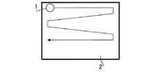
我々は、決定論的な清掃としての最大効率清掃に言及する。この最大効率清掃では、清掃レートがカバレッジレートに等しい。図1Aに示すように、決定論的な経路に追従するロボット1は、重複して清掃することなく、領域2を完全にカバーするように動く。決定論的な清掃では、ロボットが自身の現在位置及び過去の経路を認識していることが必要である。これは即ち、測位システムが必要ということである。このような測位システム(走査レーザー距離計(scanning laser ranger)、超音波変換器、搬送位相差GPS(carrier phase differential GPS)、又は他の方法を利用する、決定論的な清掃が可能とするほどに正確である測位システム)は、実現不能なほどに高価になり得るとともに、特定の部屋の幾何学的形状に個別に対応したユーザによる設定を伴う。また、全地球測位を利用する方法は、通例、測位システムのどの部分が故障しても機能しなくなる。 We refer to maximum efficiency cleaning as a deterministic cleaning. For this maximum efficiency cleaning, the cleaning rate is equal to the coverage rate. As shown in FIG. 1A, the
極めて精巧な(そして高価な)センサ技術を用いて決定論的な清掃を実現しているものの一例として、Denning Mobile Robotics and Windsor Industries製のRoboScrub装置がある。これは、ソナー(水中音波探知装置)、赤外線検出器、衝突センサ、及び高精度レーザーナビゲーションを用いたものである。RoboScrubのナビゲーションシステムでは、室内の様々な位置に大きなバーコードのターゲットを取り付けることが必要となる。また、RoboScrubが同時に少なくとも4つのターゲットを視認可能でなければならないという要件は、実用上の重大な問題である。従って、RoboScrubは、開放した広い領域の清掃用に限定されている。 The RoboScrub device from Denning Mobile Robotics and Windsor Industries is an example of one that achieves deterministic cleaning using extremely sophisticated (and expensive) sensor technology. It uses sonar (underwater sound wave detection device), infrared detector, collision sensor, and high precision laser navigation. RoboScrub's navigation system requires attaching large barcode targets at various locations in the room. Also, the requirement that RoboScrub must be able to view at least four targets simultaneously is a serious problem in practice. Therefore, RoboScrub is limited to cleaning large open areas.
他の例として、Kent Corporation製のロボットであるRoboKentも、RoboScrubと同様の全地球測位戦略に追従している。RoboKentは、RoboScrubの、より高価なレーザー測位システムを不要としているが、そうすることによって、RoboKentは、例えば長い廊下等の、単純な矩形状の領域にのみ制限される。このような、比較的制約された領域では、ソナー測距による位置補正で充分である。決定論的な清掃システムの他のものは、例えば、米国特許第4,119,900号(Kremnitz)、第4,700,427号(Knepper)、第5,353,224号(Lee et al.)、第5,537,017号(Feiten et al.)、第5,548,511号(Bancroft)、第5,650,702号(Azumi)に記述されている。 As another example, RoboKent, a robot manufactured by Kent Corporation, also follows the same global positioning strategy as RoboScrub. RoboKent eliminates the need for RoboScrub's more expensive laser positioning system, but by doing so RoboKent is limited only to simple rectangular areas, such as long corridors. In such a relatively restricted area, position correction by sonar ranging is sufficient. Other deterministic cleaning systems are described, for example, in U.S. Pat. Nos. 4,119,900 (Kremnitz), 4,700,427 (Knepper), 5,353,224 (Lee et al.), 5,537,017 (Feiten et al.), Nos. 5,548,511 (Bancroft), 5,650,702 (Azumi).
決定論的清掃の制約及び困難のため、ある種のロボットは、擬似決定論的方式に依拠している。擬似決定論的清掃を提供する一方法として、推測航法(Dead reckoning)として知られる自律型ナビゲーション方法がある。推測航法は、(例えば光学式軸エンコーダを用いて)ロボットの各駆動輪の回転を正確に計測することからなる。そして、ロボットは、既知の出発地点及び方向が与えられた状態で、推定位置を算出することができる。この技術に伴う問題として、車輪のすべりがある。すべりが生じると、車輪のエンコーダは、その車輪が地面に対してロボットを駆動していなくとも、車輪の回転を記録してしまう。図1Bに示すように、ロボット1が室内を進むにつれて、駆動輪のすべり誤差が累積するので、この種のシステムは、実用上の時間が経過した場合に信頼できないものとなってしまう。(その経路は、図1Aに示した決定論的な処理と比べると、もはや、しっかりと配列された列でできているというわけではない。)推測航法に依拠した結果、対処不能に系統的に無視されることが起こる。すなわち、床のある領域が清掃されないということである。 Some robots rely on pseudo-deterministic schemes because of the constraints and difficulties of deterministic cleaning. One way to provide pseudo-deterministic cleaning is the autonomous navigation method known as Dead reckoning. Dead reckoning consists of accurately measuring the rotation of each drive wheel of the robot (e.g. using an optical axis encoder). The robot can then calculate the estimated position given the known starting point and direction. One of the problems with this technology is wheel slippage. If slippage occurs, the wheel encoders will record the rotation of the wheel, even if the wheel is not driving the robot against the ground. As shown in FIG. 1B, as the
擬似決定論的システムの一例として、Probotics, Inc.のCyeロボットがある。Cyeは、推測航法のみに依存しているので、その推測航法システムの性能を最大化するために、大胆な基準を採用している。Cyeは、既知の場所において利用者が設けた物理的登録地点で開始しなければならない。なお、この地点において、ロボットは、その位置及び向きを決定する。そして、Cyeは、その地点から離れて移動しながら、位置を常時監視し続ける。Cyeが移動してゆくと、その位置及び方向における不確実性が増加してゆく。Cyeは、較正地点を発見不能な程にこの誤差が大きくなる前に、必ず較正地点に帰還することになっている。較正地点が移動したり、遮られたり、あるいは、車輪が過剰にすべったりした場合には、Cyeは道に迷ってしまう(迷ったことが分からないこともある)。このように、Cyeは、比較的狭くて良好な環境でのみ使用するのに適している。このアプローチの他の例が、米国特許第5,109,566号(Kobayashi et al.)及び第6,255,793号(Peless et al.)に開示されている。 An example of a pseudodeterministic system is Probotics, Inc.'s Cye robot. Since Cye relies solely on dead reckoning, it employs bold criteria to maximize the performance of its dead reckoning system. Cye must start at a physical registration point provided by the user at a known location. At this point, the robot determines its position and orientation. And Cye keeps monitoring the position constantly while moving away from the point. As Cye moves, the uncertainty in its position and orientation increases. Cye is supposed to return to the calibration point before this error becomes so large that the calibration point can not be found. If the calibration point moves, is blocked, or if the wheels slip too much, Cye may get lost (sometimes it may not be obvious). Thus, Cye is suitable for use only in a relatively narrow and good environment. Other examples of this approach are disclosed in US Pat. Nos. 5,109,566 (Kobayashi et al.) And 6,255,793 (Peless et al.).
ロボット清掃の他のアプローチとして、完全にランダムな動作のものがある。図1Cに示すように、障害物のない通常の部屋において、清掃時間がかなり長時間であれば、ランダムな動作のアルゴリズムにより、満足なカバレッジが得られる。決定論的アルゴリズムのロボットと比較して、ランダムな清掃ロボットは、満足なカバレッジを処理するのに長時間を要する。ランダムに動作するロボットは、障害物のない部屋の98%を清掃するという高い信頼度を得るのに、同じ清掃機能を有して同じ速度で動く決定論的ロボットの約5倍走行しなければならない。 Another approach to robot cleaning is that of completely random operation. As shown in FIG. 1C, in a normal room without obstacles, if the cleaning time is quite long, the random operation algorithm will provide satisfactory coverage. In comparison to deterministic algorithm robots, random cleaning robots take a long time to process satisfactory coverage. A robot operating at random must travel about five times faster than a deterministic robot with the same cleaning function and move at the same speed to get high confidence in cleaning 98% of the room without obstacles It does not.
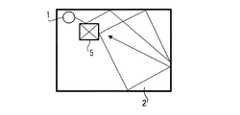
図1Dに、ランダムなアルゴリズムの処理の限界を示す。部屋の中に障害物5があると、その部屋を複数の小室の集合体として分割する効果が生じる。このような部屋におけるランダムなアルゴリズムのロボットのカバレッジの経時変化は、限定された容量の小室内で放出された気体の経時的密度に類似している。最初のうちは、気体密度は、気体が放出された小室内で最も高く、比較的離れた小室では最も低くなっている。同様に、初期段階にてロボットは、動作を開始したところの小室を、離れた小室よりも徹底的に清掃することになる。充分な時間が経過すると、気体は平衡に達して、全ての小室において密度が等しくなる。同様に、時間が経過すれば、ロボットは、全ての領域を徹底的に清掃することになる。しかしながら、実際の電源供給の制約により、通常保証されるのは、ロボットが障害物が散らかった状態の全領域を清掃するには不充分な時間にすぎない。我々は、この現象をロボット拡散問題と呼ぶ。 FIG. 1D illustrates the limits of the random algorithm process. If there is an obstacle 5 in the room, an effect of dividing the room into a group of a plurality of small rooms is produced. The temporal variation of the random algorithm robot's coverage in such rooms is similar to the temporal density of the gas released in the confined volume of the chamber. Initially, the gas density is highest in the chamber from which the gas was released and lowest in the relatively far chamber. Similarly, at an early stage, the robot will clean the compartment where it has started to move more thoroughly than the ones that are far away. After a sufficient time, the gases reach equilibrium and the density is equal in all the cells. Similarly, as time passes, the robot will thoroughly clean all areas. However, due to limitations of the actual power supply, it is usually only guaranteed that the robot has insufficient time to clean the entire area where the obstacles are scattered. We call this phenomenon the robot diffusion problem.
以上検討したように、市販されている従来例では、未知の形状の領域に対しては、効率的なカバレッジアルゴリズムが得られない。上述のように、従来技術は、マーカーやビーコンの複雑なシステムに依拠しているか、あるいは、ロボットの用途が、単純な矩形状の室内に限定されている。擬似決定論的制御アルゴリズムを用いる試みでは、体系上無視された空間領域が、残されてしまうことがある。 As discussed above, in the conventional example commercially available, an efficient coverage algorithm can not be obtained for an area of unknown shape. As mentioned above, the prior art relies on a complex system of markers and beacons, or the application of the robot is limited to a simple rectangular room. Attempts to use pseudo-deterministic control algorithms may leave a space region that is systematically ignored.
本発明の一つの目的は、様々なセンサを用いて、移動型ロボット清掃機の脱出状況を検出するとともに、脱出が不可能な状況であると決定された場合には、ロボットをオフにするよう設計される移動型ロボット清掃機を提供することである。 One object of the present invention is to detect the escape situation of the mobile robot cleaner using various sensors, and to turn off the robot when it is determined that escape is impossible. It is to provide a designed mobile robot cleaner.
本発明の目的は、効率的なカバレッジの処理ため、移動ロボットを複数のモードで動作させることが可能なシステム及び方法を提供することである。 An object of the present invention is to provide a system and method capable of operating a mobile robot in a plurality of modes for efficient coverage processing.
また、本発明の目的は、少なくとも1個のセンサを具備して、スポット処理、障害物追従、及び反跳(はね返り)等のいくつかのモードで動作する移動ロボットを提供することである。 It is also an object of the present invention to provide a mobile robot equipped with at least one sensor and operating in several modes, such as spot handling, obstacle tracking, and recoil.
本発明の更なる目的は、カバレッジを確実にするために、障害物追従モードと反跳モードとを交互に繰り返す移動ロボットを提供することである。 A further object of the present invention is to provide a mobile robot that alternates between an obstacle following mode and a recoil mode to ensure coverage.
本発明の一つの目的は、ロボットが所定の距離を移動した後に、スポット処理へと復帰させることである。 One object of the present invention is to return to spot processing after the robot has moved a predetermined distance.
本発明の一つの目的は、障害物間の平均距離を監視し、該平均距離を動作モードを入れ替えるための入力として用いることが可能な移動ロボットを提供することである。 One object of the present invention is to provide a mobile robot capable of monitoring an average distance between obstacles and using the average distance as an input for switching the operation mode.
本発明の別の目的は、ロボットが障害物追従モードで移動する距離を、障害物追従の頻度及びロボットの動作有効幅の関数として最適化し、障害物追従モードにて動作する最小距離および最大距離を提供することである。 Another object of the present invention is to optimize the distance traveled by the robot in obstacle tracking mode as a function of the frequency of obstacle tracking and the effective width of robot movement, and the minimum and maximum distances for operating in obstacle tracking mode To provide.
本発明の一つの目的は、複数の行動を実行可能なオペレーション・システムプログラムを有する移動ロボットのための制御システムを採用し、アービタ(arbiter)を用いて、ロボットにどの行動を取らせるかを選択させることである。 One object of the present invention is to adopt a control system for a mobile robot having an operation system program capable of executing a plurality of actions and select which action the robot should take using an arbiter. It is to
本発明の別の目的は、様々な脱出プログラムや行動を組み込んで、ロボットがスタックしないようにすることである。 Another object of the present invention is to incorporate various escape programs and actions so that the robots do not stack.
最後に、本発明の一つの目的は、ここに開示された様々な目的及び利点を活かすように移動ロボットを制御する1つ又はそれ以上の方法を提供することである。 Finally, it is an object of the present invention to provide one or more methods of controlling a mobile robot to take advantage of the various objects and advantages disclosed herein.
上記目的のため、本発明において、任意の大きさおよび形状を有する床面を清掃する移動型ロボット清掃機であって、移動型ロボット清掃機を床面上で移動させる移動手段と、移動型ロボット清掃機の移動中に移動型ロボット清掃機が接触または近接する障害物を検出する衝突センサと、絶壁を検出する絶壁センサと、衝突センサと絶壁センサからの出力信号に基づいて、移動手段を制御するコントローラと、を備える移動型ロボット清掃機が提供される。また、上記コントローラは、絶壁センサが所定時間を超えて絶壁を検出すると、移動手段による移動型ロボット清掃機の移動を停止することを特徴とする。 To the above object, in the present invention, a mobile robot cleaning device for cleaning a floor surface having any size and shape, which is a moving means for moving a mobile robot cleaning device on the floor surface, a mobile robot The moving means is controlled based on output signals from the collision sensor and the collision sensor and the collision sensor detecting the collision, which detects an obstacle that the mobile robot cleaner contacts or approaches while the cleaner is moving, and the cliff. And a controller. Further, the controller is characterized in that the movement of the mobile robot cleaner by the movement means is stopped when the cliff sensor detects a cliff exceeding a predetermined time.
従って、本発明によれば、各センサの出力信号に基づいて、移動型ロボット清掃機の状態を判断し、移動ロボット清掃機がスタックしないようにすることができるとともに、スタックしたと判断された場合には移動を停止することにより、バッテリ寿命を保つことが可能な移動型ロボット清掃機を提供することができる。 Therefore, according to the present invention, the state of the mobile robot cleaner can be determined based on the output signal of each sensor, and the mobile robot cleaner can be prevented from being stacked, and it is determined that the mobile robot cleaner is stacked. By stopping the movement, it is possible to provide a mobile robot cleaner capable of maintaining the battery life.
本発明のこれらの特徴及びさらなる特徴は、添付の図面を参照して明らかとなるであろう。 These and further features of the present invention will be apparent with reference to the attached drawings.
本発明では、移動ロボットが、未知の幾何学形状の部屋において有効な処理速度にて最大のカバレッジを提供するように、設計されている。また、パターン化された動作すなわち計画的動作が組み込まれているために、ロボットの知覚効率が向上している。さらに、好適な実施形態では、効率的に処理するためには、ロボットが未知の環境内で動作不能となることを防止できる制御システムが必要である。 In the present invention, the mobile robot is designed to provide maximum coverage at effective processing speeds in rooms of unknown geometry. Also, the perceptual efficiency of the robot is improved due to the incorporation of patterned or planned motion. Furthermore, in the preferred embodiment, to process efficiently, a control system is needed that can prevent the robot from becoming inoperable in an unknown environment.
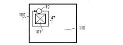
移動ロボットの物理的構成は、当該技術分野において既知であるので、ここでは、本発明の好適な、そして例示的な実施形態における構成要素について説明する。本発明の好適な一実施形態は、ある特徴を備えたほぼ円形状のロボット掃除機である。例えば図2に示すように、好適な実施形態の移動ロボット10は、シャーシ11を備え、このシャーシ11には、機械的及び電気的構成要素が支持されている。これらの構成要素として、種々のセンサが含まれており、その中には、ロボットの前側部分に配置された2つの衝突センサ12、13、ロボットのシエル(以下、ケースと記す)15に配置された4つの絶壁センサ14、及びロボットのケース15に搭載された壁面追従センサ16が含まれる。他の実施形態では、ロボットに1つだけのセンサが用いられてもよい。センサとしては、ソナー型、触覚型、電磁型、静電容量型等の様々な型のセンサが用いられてもよいことが、当業者には理解されるであろう。コスト上の制約により、本発明の好適な実施形態においては、衝突(触覚)センサ12、13と、絶壁センサ14及び壁面追従センサ16として反射型赤外線近接センサとが、用いられている。赤外線センサの詳細は、米国特許出願No. (U.S.S.N.)09/768,773に記載されている。この米国特許出願No. 09/768,773の開示は、ここに参照することにより本明細書に一体に組み入れられるものとする。 As the physical configuration of the mobile robot is known in the art, the components in the preferred and exemplary embodiments of the present invention will now be described. A preferred embodiment of the present invention is a generally circular robot cleaner with certain features. For example, as shown in FIG. 2, the
ロボットの好適な実施形態は、2つの車輪20、該車輪をそれぞれ独立して回転させるモータ21、安価なローエンド・マイクロコントローラ22、及び充電可能なバッテリ23又は当該技術に既知の他の電源を備えている。これらの構成要素は当該技術で周知であるため、ここで詳細には説明しない。さらに、ロボット清掃機10は、1つ又はそれ以上の清掃ヘッド30を備えている。この清掃ヘッドは、真空掃除機、様々なブラシ、スポンジ、モップ、静電布、又は様々な清掃要素を組み合わせたものを含む。また、図2に示す実施形態には、サイドブラシ(side brush)32も含まれている。 The preferred embodiment of the robot comprises two
上述のように、ロボット清掃機10の好適な実施形態は、外側ケース15を備えており、該外側ケース15において、そのロボット10における支配的な側、非支配的な側、及び前側部分が規定されている。ロボットの支配的な側とは、ロボットが物体(又は障害物)の近傍を清掃するとき、その物体(又は障害物)に対して近接又は当接した状態に保たれる側のことである。図2に示すように、好適な実施形態では、ロボット10の支配的な側は、主たる進行方向に対し右手側となっている。但し、他の実施形態では、支配的な側が左手側であってもよい。さらに別の実施形態では、ロボットは対称であってもよく、その場合、支配的な側は必要でない。しかしながら、好適な実施形態では、コストの理由から支配的な側が選択されている。主たる進行方向を図2において、矢印40で示す。 As mentioned above, the preferred embodiment of the
好適な実施形態では、2つの衝突センサ12、13が、矢印40で示した前進方向を基準として、車輪20の前方に配置されている。一方の衝突センサ13は、ロボット10の支配的な側に配置されており、他方の衝突センサ12は、ロボット10の非支配的な側に配置されている。これら両衝突センサ12、13が同時に作動したとき、ロボット10は、障害物が前方にあることを認識する。他の実施形態では、より多数又はより少数の衝突センサが用いられてもよい。同様に、任意の数の衝突センサが、清掃機を任意の数の放射状部分に区分するのに用いられてもよい。好適な実施形態では、衝突センサ12、13は、ロボット10と障害物とが接触すると作動する赤外線遮断センサであるが、機械スイッチや、ロボットに接触した物体の静電容量あるいは、接触時にバンパ内で圧縮される2枚の金属板間の静電容量を検出する静電容量型センサを含む他の型のセンサが用いられてもよい。非接触センサは、ロボットが物体に対して近接したことを、その物体に物理的に接触することなく検出可能であるが、非接触センサが用いられても良い。非接触センサとしては、静電容量センサや赤外光のカーテン(curtain of IR light)等がある。 In the preferred embodiment, two
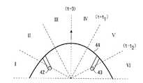
表面が接触(又は近接)したことだけでなく、接触したところのロボットに対する角度をも通知可能なセンサを備えていると、便利である。好適な実施形態では、ロボットは、左右の衝突スイッチ12、13が作動した場合に、両者の作動の時間差を算出することができる。そして、ロボットは、接触した角度を推定することができる。図4Aに示した好適な実施形態では、衝突センサは、ロボットの前側に、センサ42、43を有する単一の機械式バンパ44を備えている。センサ42、43は、バンパのほぼ両端にあり、該バンパの動作を検出する。バンパが圧縮されると、センサの事象同士の時間差が、ロボットが障害物に接触した角度を概算するのに用いられる。バンパが右側から圧縮された場合、バンパの追従及び衝突検出器の幾何学的形状により、右側の衝突センサが最初に衝突を検出し、引き続き、左側の衝突センサが衝突を検出する。このように、2つの衝突センサだけで、衝突角度を概算することができる。 It is convenient to have a sensor that can notify not only the contact (or proximity) of the surface, but also the angle to the robot at the contact. In a preferred embodiment, the robot can calculate the time difference between the left and right collision switches 12 and 13 when the two are activated. The robot can then estimate the angle of contact. In the preferred embodiment shown in FIG. 4A, the collision sensor comprises a single
例えば、図4Aでは、衝突センサ42,43は、ロボットの前側部分を6つの領域(I〜VI)に分割可能である。1つの衝突センサが作動すると、ロボットは、他のセンサが作動するまでの(仮に作動するとして)時間を算定する。例えば、右側の衝突センサ43が作動すると、ロボットは、左側の衝突センサ42が作動するまでの時間(t)を測定する。tがt1未満であれば、ロボットは、接触が領域IVで発生したものとみなす。tがt1以上かつt2未満であれば、ロボットは、接触が領域Vで発生したものとみなす。tがt2以上(監視時間内に左側の衝突センサ42が全く作動しない場合を含む)であれば、ロボットは、接触が領域VIで発生したものとみなす。衝突センサが同時に作動した場合には、ロボットは、接触がまっすぐ前で発生したものとみなす。この方法は、使用される時間測定及びバンパの幾何学的形状次第で、バンパを任意の多数の領域に(より高精度で)分割するのに用いられてもよい。機能拡張として、上記の例のように2次元だけとする代わりに、3次元で衝突角度を算出するのに、3つのセンサを用いてもよい。For example, in FIG. 4A, the
また、好適な実施形態においては、ロボット10の支配的な側、壁面追従すなわち壁面検出センサ16が取り付けられている。好適な実施形態では、壁面追従センサは、壁面がしかるべき位置にある時、有限の大きさで壁面と交差するようにコリメートされた、発光器及び検出器の対からなる赤外線センサである。この焦点は、ロボットの前進動作方向において、駆動車輪よりも約3インチ前方に位置している。壁面検出の半径範囲は、約0.75インチである。 Also, in the preferred embodiment, the dominant side of the
また、好適な実施形態は、任意の個数の赤外線絶壁センサ14を備えており、これによって、清掃機が階段や他の垂直の落ち込みで転落しないようになっている。これら絶壁センサは、壁面追従センサと同様の構成であるが、壁ではなく床を観測する向きに配設されている。さらなる安全性及び検出手段として、ロボット10は、1つ又はそれ以上の車輪が床に支持されなくなったときにそれを検出可能な脱輪センサを備えている。従って、この脱輪センサは、絶壁だけでなく、電気スタンドの基部、床が高くなっているところ、コードの束等のように、ロボットがその上を走行し得る様々な障害物をも検出可能である。 Also, the preferred embodiment includes any number of
他の実施形態では、他の既知のセンサあるいはセンサの組み合わせが用いられてもよい。 In other embodiments, other known sensors or combinations of sensors may be used.
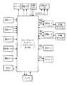
図3に、本発明の好適な実施形態のコントローラ及びロボットのハードウェアブロック図を示す。好適な実施形態では、Winbond W78XXXシリーズのプロセッサが用いられている。これは、36個の汎用I/Oポート、256バイトのRAM、及び16KのROMを有するMCS-51ファミリーと互換性のあるマイクロコントローラである。クロックは40MHzになっており、それが分割されて、プロセッサ速度が3.3MHzとなる。このプロセッサは、2つのタイマを備えている。これらのタイマは、ウォッチドッグタイマとしても使用され、また、センサを処理して出力信号を発生する、割り込み処理を起動するのにも使用される。また、第1のタイマの最下位ビットは、行動に必要となる擬似乱数として用いられる。また、2つの駆動輪からのエンコーダ入力を取り込むのに用いる2つの外部割込みがある。また、プロセッサは、ロボット制御プログラムのテスト及びデバッグに用いるUARTを有する。 FIG. 3 shows a hardware block diagram of the controller and robot of the preferred embodiment of the present invention. In the preferred embodiment, a Winbond W78XXX series processor is used. It is a microcontroller compatible with the MCS-51 family with 36 general purpose I / O ports, 256 bytes of RAM, and 16K of ROM. The clock is at 40 MHz and it is split to a processor speed of 3.3 MHz. This processor is equipped with two timers. These timers are also used as watchdog timers and are also used to trigger interrupt processing, which processes the sensor and generates an output signal. Also, the least significant bit of the first timer is used as a pseudo-random number required for action. There are also two external interrupts that are used to capture the encoder input from the two drive wheels. The processor also has a UART that is used to test and debug the robot control program.
マイクロプロセッサのI/Oポートは、ロボットのセンサ及びモータに接続されており、ロボットの内部状態及びその環境に接続するインタフェースとなっている。例えば、脱輪センサが入力ポートに接続され、ブラシモータPWM信号が出力ポートに発生する。マイクロプロセッサ上のROMは、カバレッジ及びロボットの制御プログラムを格納するのに用いられる。これには、行動(後述)、センサ処理アルゴリズム、及び信号発生が含まれている。RAMは、平均衝突距離、走行時間及び距離、並びに制御上の行動ID及びその現在のモータコマンド等のロボットの動的状態を格納するのに用いられる。 The microprocessor's I / O port is connected to the robot's sensors and motor and provides an interface to the robot's internal state and its environment. For example, a derailing sensor is connected to the input port and a brush motor PWM signal is generated at the output port. The ROM on the microprocessor is used to store the coverage and control program of the robot. This includes actions (described below), sensor processing algorithms, and signal generation. The RAM is used to store the robot's dynamic state such as average collision distance, travel time and distance, and control action ID and its current motor command.
ロボット清掃機の移動を理解するため、図4Bに、座標平面上のx軸及びy軸の中心を基準とするロボットの方位を示す。この座標システムは、ロボットにも採用されている。ロボット10の方向に関する動作は、ロボット10が移動する半径として理解することができる。敏速に回転して壁100から離反するためには、ロボット10は、正の小さい値r(図4Bではr3)を設定する。また、敏速に回転して壁へと向かうためには、ロボットは、負の小さな値r(図4Bではr1)を設定する。一方、わずかに回転するためには、ロボットは、比較的大きな絶対値rを設定する。左回転するには(すなわち壁から離反するには)、正の値r、(図4Bではr4)で、右回転するには(すなわち壁に向かってゆくには)、負の値r(図4Bではr2)を設定する。この座標を用いた体系(scheme)は、後述の制御の例で用いられる。マイクロコントローラ22は、速度差を制御して回転半径を決定する。その速度差とは、各モータ21が個別に稼動するそれぞれの速度の差である。To understand the movement of the robot cleaner, FIG. 4B shows the orientation of the robot with respect to the centers of the x and y axes on the coordinate plane. This coordinate system is also adopted for robots. The motion related to the direction of the
また、ある実施形態では、ロボットは、1つ又はそれ以上の利用者の入力手段が含まれる。例えば、図2に示すように、好適な実施形態には、3つの単純なボタン33が含まれている。これらのボタン33により、利用者はカバーされる表面の概略の広さを入力可能である。好適な実施形態では、これらのボタンには、「S」(小)、「M」(中)及び「L」(大)のラベルが付されており、それぞれ、11.1、20.8及び27.9平方メートルの部屋に対応している。 Also, in one embodiment, the robot includes one or more user input means. For example, as shown in FIG. 2, the preferred embodiment includes three
上述のように、例示したロボットは、本発明を実施するのに好適な実施形態であり、当業者は、当該分野で既知の構成要素を選択して、特定の目的用にロボットを設計することができる。好適な設計例としては、以下の米国特許に記述されているものを含む。すなわち、米国特許第4,306,329号 (Yokoi)、第5,109,566号(Kobayashi et al.)、第5,293,955号(Lee)、第5,369,347号(Yoo)、第5,440,216号(Kim)、第5,534,762号 (Kim)、第5,613,261号(Kawakami et al.)、第5,634,237号(Paranjpe)、第5,781,960号(Kilstrom et al.)、第5,787,545号(Colens)、第5,815,880号(Nakannishi)、第5,839,156号(Park et al.)、第5,926,909号(McGee)、第6,038,501号(Kawakami)、第6,076,226号(Reed)であり、これらは、ここに参照することにより、本明細書に一体に組み入れられるものとする。 As mentioned above, the illustrated robot is a preferred embodiment for practicing the present invention, and one of ordinary skill in the art would select components known in the art to design the robot for a specific purpose. Can. Examples of suitable designs include those described in the following US Patents. That is, U.S. Patent Nos. 4,306,329 (Yokoi), 5,109,566 (Kobayashi et al.), 5,293,955 (Lee), 5,369,347 (Yoo), 5,440,216 (Kim), 5,534,762 (Kim), 5,613,261 (Kawakami et al.), 5,634,237 (Paranjpe), 5,781,960 (Kilstrom et al.), 5,787,545 (Colens), 5,815,880 (Nakannishi), 5,839,156 (Park et al.), Nos. 5,926,909 (McGee), 6,038,501 (Kawakami), 6,076,226 (Reed), which are hereby incorporated by reference in their entirety.
図5は、清掃機の様々な動作モードの簡略ブロック図である。好適な実施形態では、そして単なる例としてであるが、動作モードには、スポット清掃(利用者又はロボットが清掃の特定の領域を指定する)、縁端清掃、及び室内清掃がある。各動作モードは、後述するように、命令及び/又は内部行動の複雑な組み合わせを含んでいる。但し、そのような複雑さは、利用者には通常わからないようになっている。一実施形態では、利用者は、例えばセレクタスイッチや押しボタンのような入力要素を用いて特定の動作モードを選択することができる。別の好適な実施形態では、以下に説明するように、ロボットは、複数の動作モード間を自律的に循環してゆく。 FIG. 5 is a simplified block diagram of various operating modes of the cleaner. In the preferred embodiment, and by way of example only, the modes of operation include spot cleaning (the user or robot specifies a particular area of cleaning), edge cleaning, and room cleaning. Each mode of operation includes complex combinations of instructions and / or internal actions, as described below. However, such complexity is usually not understood by the user. In one embodiment, the user can select a particular operating mode using input elements such as, for example, a selector switch or a push button. In another preferred embodiment, the robot autonomously circulates between a plurality of operating modes, as described below.
本発明のカバレッジロボットは、領域を効率的にカバーするのに、これらの様々な動作モードを用いる。当業者はこれらの様々な動作モードを様々なアーキテクチャーで構成できるが、好適な実施形態では、行動制御に依拠している。ここで行動とは、単に、相互に並列して実行される制御システムの複数の層のことである。そして、マイクロコントローラ22は、優先度が付された裁定スキームを実行して、所与のシナリオに対する支配的な行動を解決する。行動制御の説明は、Mobile Robots, supraに見られ、その本文は、ここに参照することにより本明細書に一体に組み入れられているものとする。 The coverage robot of the present invention uses these various operating modes to efficiently cover the area. Those skilled in the art can configure these different modes of operation in different architectures, but in the preferred embodiment relies on behavioral control. Here, action is simply the layers of the control system that are implemented in parallel with one another. The
すなわち、好適な実施形態では、ロボットのマイクロプロセッサ及び制御ソフトウェアは、多数の行動を同時に実行する。状況に応じて、ロボットの制御は、1つ又はそれ以上の様々な行動をもたらす。本発明の好適な動作を詳述する目的で、行動は、(1)カバー行動、(2)脱出行動、又は(3)利用者/安全行動として説明される。カバー行動は、主として、ロボットがカバー動作を効率的に実行できるように設計されている。脱出行動は、1つ又はそれ以上のセンサがロボットに自由な行動が許されていないことを示唆した場合に、優先的に実行される特別な行動である。本明細書の約束事として、以下に検討する行動は、全て大文字で記述される。 That is, in the preferred embodiment, the robot's microprocessor and control software execute multiple actions simultaneously. Depending on the situation, control of the robot results in one or more different actions. For the purpose of detailing the preferred behavior of the present invention, the behavior is described as (1) cover behavior, (2) escape behavior, or (3) user / safety behavior. The covering behavior is primarily designed to allow the robot to perform the covering action efficiently. The escape action is a special action that is preferentially performed when one or more sensors indicate that the robot is not allowed free action. As a convention of this specification, the actions discussed below are described in all capital letters.
1.カバレッジ行動(Coverage Behaviors)
図6乃至図14に、好適な各動作モード、すなわち、スポットカバレッジ、壁面追従(又は障害物追従)、及び室内カバレッジについての詳細を示す。1. Coverage Behavior
6 to 14 show details of the preferred operating modes: spot coverage, wall following (or obstacle following), and indoor coverage.
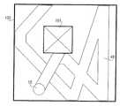
動作モード:スポットカバレッジ例えばスポット清掃により、利用者は孤立した状態の汚れた領域を清掃可能である。利用者は、ロボット10を、清掃が必要な領域の中央近傍の床面上に配置し、スポット清掃動作モードを選択する。すると、ロボットは、例えば規定の半径内の近接領域にロボットの清掃ヘッド30やサイドブラシ32が接するように動作する。 Mode of operation: Spot coverage, eg spot cleaning, allows the user to clean isolated soiled areas. The user places the
好適な実施形態では、スポット清掃を実現する方法は、図6Aに示すような外向きの螺旋運動すなわちSPIRAL行動を提供する制御アルゴリズムである。一般に、螺旋運動は、回転半径が時間の関数として増加させることにより実現させる。好適な実施形態では、支配的な側を、螺旋における外側、すなわち最前線側に維持するため、ロボット10の螺旋運動を反時計回りに開始する(図6Aに移動線45で示す)。図6Bに示す他の実施形態では、ロボット10の螺旋運動は、回転半径が減り続けるように、内方へと発生する。内向き螺旋を、図6Bに移動線45として示す。しかしながら、螺旋運動中に支配的な側を外側に保つことは、必須ではない。 In the preferred embodiment, the method of achieving spot cleaning is a control algorithm that provides outward spiral motion or SPIRAL behavior as shown in FIG. 6A. In general, helical motion is realized by increasing the turning radius as a function of time. In the preferred embodiment, the spiral movement of the
好適な実施形態で用いるスポット清掃方法(外向きスパイラル)を、図7で説明する。まず、螺旋運動が開始され(ステップ201)、rの値がその最小の正の値に設定される(可能な限り急な反時計方向の回転が生じる)と、螺旋行動は、θを螺旋行動開始時以降の角度変化を表すものとし、rの値をθの関数として再計算する(ステップ210)。式r=aθ(aは定数)を用いることにより、螺旋のきつさ、あるいは螺旋の所望の重複が制御可能である。(なお、θは、2πに規格化されていない。)aの値は、式a=d/(2π)で選択される。ここで、dは、螺旋の連続した2つの経路間の距離である。効率的な清掃のためには、dの値は、清掃機構30の幅未満とすべきである。好適な実施形態では、dの値は、清掃ヘッド30の幅の1/2乃至2/3に設定される。 The spot cleaning method (outward spiral) used in the preferred embodiment is described in FIG. First, when the helical motion is started (step 201) and the value of r is set to its smallest positive value (causing as fast as possible a counterclockwise rotation), the helical behavior is to θ the helical behavior The angle change after the start is assumed to be represented, and the value of r is recalculated as a function of θ (step 210). By using the equation r = aθ (a is a constant), the tightness of the helix or the desired overlap of the helix can be controlled. (Note that θ is not normalized to 2π.) The value of a is selected by the equation a = d / (2π). Here, d is the distance between two successive paths of the spiral. For efficient cleaning, the value of d should be less than the width of the
他の実施形態では、ロボットは、螺旋モードで移動した合計距離を記録している。それは、ある距離になると螺旋が崩れる、すなわち、表面に依存した車輪のすべり及び/又は螺旋概算アルゴリズムと計算精度の不正確さのため、時間が経過すると螺旋運動の中心点がずれる傾向にあるためである。ある実施形態では、ロボットは、6.3又は18.5メートルといった所定の距離(「最大螺旋距離」)を移動(ステップ240)した後に、螺旋モードから離脱する。好適な実施形態では、ロボットは、最初の螺旋を実行しているか又は後の螺旋を実行しているのかに依存する、複数の最大螺旋距離を用いる。衝突することなく最大螺旋距離に達した場合には、ロボットは、別の行動に制御を移し、例えば、主に直線に沿って移動を続ける。(好適な実施形態では、直線(STRAIGHT LINE)行動は、優先度の低いデフォルトの行動である。この行動は、他の行動がアクティブでないときに、ロボットをほぼ直線に沿って、約0.306m/sの予め設定された速度で進行させる。 In another embodiment, the robot records the total distance traveled in the spiral mode. That is because the spiral breaks down at a certain distance, that is, the center point of the spiral movement tends to shift over time due to surface-dependent wheel slip and / or inaccuracies in the helical approximation algorithm and calculation accuracy. It is. In one embodiment, the robot moves out of the spiral mode after moving (step 240) a predetermined distance ("maximum spiral distance") such as 6.3 or 18.5 meters. In a preferred embodiment, the robot uses a plurality of maximum spiral distances depending on whether it is executing the first spiral or the second spiral. If the maximum spiral distance is reached without collision, the robot transfers control to another action, for example, continues to move mainly along a straight line. (In the preferred embodiment, STRAIGHT LINE behavior is a low priority default behavior. This behavior is approximately 0.306 m / m along the robot's straight line when no other activity is active. Proceed at a preset speed of s.
螺旋モードでは、障害物に遭遇した場合に様々な動作がなされる。例えば、ロボットは、(a)障害物を回避して反時計回りの螺旋運動を続けようとするか、(b)障害物を回避して反対方向に螺旋運動を続けようとする(例えば、反時計回りから時計回りに変更する)か、又は(c)動作モードを変更する。螺旋運動を逆回りで継続するのは、反射螺旋(reflective spiral)として知られており、図6Cに示されている。ここでは、ロボット10は、障害物101に接触したときに、動作経路45を反転させている。好適な実施形態では、ステップ220に詳述するように、衝突センサ12又は13が最初の障害物に遭遇したときに、ロボット10はスポット清掃モードから離脱する(ステップ230)。 In the spiral mode, various actions are taken when an obstacle is encountered. For example, the robot may either (a) try to avoid the obstacle and try to continue the counterclockwise spiral movement, or (b) try to avoid the obstacle and keep the spiral movement in the opposite direction (e.g. Change from clockwise to clockwise) or (c) change the operating mode. Continuing the helical motion back is known as a reflective spiral and is shown in FIG. 6C. Here, when the
好適な実施形態は、スポットカバーについて、螺旋運動により説明しているが、自身により境界を設定する任意の領域が使用可能である。このような領域には、制限するものではないが、正方形や六角形等の通常の多角形状及び楕円形状等が含まれる。 Although the preferred embodiment describes the spot cover with a helical motion, any area bounded by itself can be used. Such regions include, but are not limited to, regular polygonal shapes such as squares and hexagons and elliptical shapes.
動作モード:壁面/障害物追従
壁面追従、すなわち清掃ロボットの場合には縁端清掃により、利用者は、部屋の縁端や室内の物体の縁端のみを清掃可能である。利用者は、清掃すべき縁端の近傍の床面上にロボット10を配置し、縁端清掃動作モードを選択する。すると、ロボット10は、縁端を辿りつつ、ロボットの清掃ヘッド30が当接した全ての領域を清掃する。Mode of Operation: Wall / Obstacle Follow Wall follow, or edge cleaning in the case of a cleaning robot, allows the user to clean only the edge of a room or the edge of an object within a room. The user places the
図8に、部屋110の中でのロボット10の動作を示す。図8Aにおいて、ロボット10は、その支配的な側が壁面に隣接するように、壁面100に沿って配置される。すると、ロボットは、壁面に沿って、無制限に移動経路46を辿って走行する。同様に、図8Bでは、ロボット10は、障害物101に近接して配置される。すると、ロボットは、障害物101の縁辺に沿って、無制限に移動経路47を辿る。 The operation of the
好適な実施形態における壁面追従モードでは、ロボットは、壁面追従センサ16を用いて、自身の位置を壁から所定の距離に位置させる。そして、ロボットは、壁の周囲に沿って移動する。図8A及び図8Bに示すように、好適な実施形態においては、ロボット10は、壁100と他の固体の障害物101とを区別できない。 In the wall follow mode in the preferred embodiment, the robot uses the
図9Aに、好適な実施形態において壁面追従に用いられている、1ビットのセンサでも、滑らかな壁面追従動作が得られる方法を示す。(ここで、1ビットのセンサは、壁とセンサとの間の距離ではなく、特定の体積内において壁が存在するかしないかのみを検出する。)衝突検出やソナーセンサ等の、壁や物体を検出する他の方法が用いられてもよい。 FIG. 9A shows how a smooth wall following operation can be obtained even with a 1-bit sensor used for wall following in the preferred embodiment. (Here, a 1-bit sensor detects only the presence or absence of a wall in a specific volume, not the distance between the wall and the sensor.) Walls or objects, such as collision detection or sonar sensors Other methods of detection may be used.
壁面追従動作モード、すなわち好適な実施形態の壁面追従(WALL FOLLOWING)行動、が開始されると(ステップ301)、最初にロボットは、操舵のための初期値をr0に設定する。そして、壁面追従(WALL FOLLOWING)行動は、壁面追従センサ16における発光−検出(emit-detect)ルーチンを開始する(ステップ310)。センサ16の赤外線発光部分に対する反射があると、それは、センサ16から所定の距離内に物体が存在しているものと解釈される。そして、壁面追従(WALL FOLLOWING)行動は、反射(物体が範囲内にある)から非反射(物体が範囲外となる)への遷移があったかどうかを判別する(ステップ320)。そのような遷移があった(すなわち、今や壁は範囲外にある)場合、rの値は最小値(絶対値が最大の負の値)に設定され、ロボットはわずかに右方へと向きを変える(ステップ325)。そして、ロボットは、発光−検出シーケンスを再開する(ステップ310)。反射から非反射への遷移がなかった場合、壁面追従(WALL FOLLOWING)行動は、非反射から反射への遷移があったかどうかを判別する(ステップ330)。そのような遷移があった場合には、rの値は、正の最大値に設定され、ロボットはわずかに左方へと向きを変える(ステップ335)。Wall-following mode, i.e. the wall following of a preferred embodiment (WALL FOLLOWING) behavior and is started (step 301), the first robot sets an initial value for the steering to r0. Then, the wall-following (WALL FOLLOWING) action starts an emission-detect (emit-detect) routine in the wall-following sensor 16 (step 310). The reflection on the infrared emitting part of the
いずれのタイプの遷移事象も発生していなければ、壁面追従(WALL FOLLOWING)行動は、rの絶対値を低減した上で(ステップ340)、発光−検出シーケンス(ステップ310)を再開する。rの絶対値が減少することにより、ロボット10は、現在向いている方向がどちらであるにせよ、より鋭く回転するようになる。好適な実施形態では、rの絶対値の減少率は、移動距離に依存した一定の率となっている。 If neither type of transition event has occurred, then the wall-following (WALL FOLLOWING) action resumes the light emission-detection sequence (step 310) after reducing the absolute value of r (step 340). As the absolute value of r decreases, the
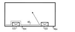
壁面追従モードは、所定時間又はランダムな時間、所定距離又はランダムな距離、あるいは、ある追加条件が満たされるまで(例えば衝突センサが作動すること等)、継続し得る。ある実施形態では、ロボットは、壁面追従をいつまでも継続する。好適な実施形態では、図8C及び図8Dに示すように、最小移動距離及(Min)び最大移動距離(Max)が定められ、ロボットは、最大移動距離に達する(図8D)か、あるいは少なくとも最小移動距離を移動した後に障害物に突き当たる(図8C)まで、壁面追従(WALL FOLLOWING)行動を続ける。このような壁面追従(WALL FOLLOWING)行動の実装により、ロボットは、他の動作モードに比べて、適切な時間、壁面追従行動をとることが保証され、これにより全領域について、カバレッジ(coverage)を、体系的に無視することなく分布させる。壁面追従を増やすことにより、ロボットはより広い空間を移動可能となるが、ある一部の空間の清掃に関しては効率が低下する。なお、障害物検出後に壁面追従(WALL FOLLOWING)行動から離脱する傾向にあると、知覚効率は向上する。 The wall-following mode may continue for a predetermined or random time, a predetermined or random distance, or until some additional condition is met (eg, the collision sensor is activated, etc.). In one embodiment, the robot continues to follow the wall indefinitely. In a preferred embodiment, as shown in FIGS. 8C and 8D, a minimum travel distance and a minimum travel distance (Max) are determined, and the robot reaches the maximum travel distance (FIG. 8D), or at least Continue to follow the WALL FOLLOWING behavior until you hit the obstacle after moving the minimum travel distance (Figure 8C). Implementation of such wall-following (WALL FOLLOWING) behavior ensures that the robot will follow the wall-following behavior for an appropriate time, as compared to other operating modes, thereby providing coverage for the entire area. , Systematically distributed without neglect. By increasing the wall following, the robot can move in a larger space, but the efficiency is reduced with regard to the cleaning of a part of the space. In addition, perceptual efficiency improves, when it exists in the tendency to remove | deviate from wall surface tracking (WALL FOLLOWING) action after an obstacle detection.
図9Bは、どのような場合に壁面追従(WALL FOLLOWING)行動から離脱するかを決定する本実施形態を示すフローチャートである。ロボットは、まず壁面追従の最小距離(dmin)及び壁面追従の最大距離(dmax)を、決定する。壁面(又は障害物)追従モードにあるとき、制御システムは、そのモードにてロボットが移動した距離(dWF)を監視している。もしもdWFがdmaxより大きくなった場合(ステップ350)、ロボットは、壁面追従モードから離脱する(ステップ380)。一方、dWFがdmax以下(ステップ350)であるとともに、dWFがdmin以下(ステップ360)である場合には、ロボットは、壁面追従モードに留まる(ステップ385)。もしもdWFがdminより大きく(ステップ360)、かつ障害物に遭遇した(ステップ370)場合には、ロボットは、壁面追従モードから離脱する(ステップ380)。FIG. 9B is a flow chart illustrating the present embodiment of determining when to exit from the wall-following (WALL FOLLOWING) behavior. The robot first determines the wall follow minimum distance (dmin ) and the wall follow maximum distance (dmax ). When in the wall (or obstacle) tracking mode, the control system is monitoring the distance the robot has moved in that mode (dWF ). If dWF is greater than dmax (step 350), the robot exits wall-following mode (step 380). On the other hand, if dWF is less than or equal to dmax (step 350) and if dWF is less than or equal to dmin (step 360), the robot remains in the wall following mode (step 385). If dWF is greater than dmin (step 360) and an obstacle is encountered (step 370), the robot exits the wall following mode (step 380).
理論的には、ロボットが壁面追従(WALL FOLLOWING)行動において移動する最適距離は、室内の広さと構成、並びにロボットの大きさの関数である。好適な実施形態では、壁面追従(WALL FOLLOWING)行動に留まるための最小距離及び最大距離は、室内のおおよその広さ、ロボットの幅、及びランダム要素に基づいて設定される。ここで、平均移動距離の最小値は、2w/pである。但し、wはロボットの作動要素の幅であり、pは障害物との所与の相互作用にてロボットが壁面追従(WALL FOLLOWING)行動に入る確率である。好適な実施形態においては、例えば、wは約15cmから約25cmの間であり、pは0.095である(障害物追従モードに入る前にロボットが6から15個の障害物に遭遇、すなわち平均で10.5個の障害物に遭遇の場合)。次に、最小距離が約115cmから約350cmの間でランダムに設定され、そして、最大距離が約170cmから約520cmの間でランダムに設定される。ある実施形態では、最大距離と最小距離との比は、2:3になっている。知覚効率のために、障害物追従モードにおけるロボットの初期の動作における距離は、障害物追従モードにおけるその後の動作よりも長く設定されていてもよい。また、利用者はロボットを始動させるときに、最も長い壁に沿ってそのロボットを配置してもよい。そうすることにより、知覚されるカバレッジ(coverage)も実際のカバレッジ(coverage)も広くなる。 In theory, the optimal distance traveled by the robot in WALL FOLLOWING behavior is a function of the room size and configuration as well as the size of the robot. In a preferred embodiment, the minimum and maximum distances for staying in wall follow behavior are set based on approximate room size, robot width, and random factors. Here, the minimum value of the average movement distance is 2 w / p. Where w is the width of the actuating element of the robot and p is the probability that the robot will enter WALL FOLLOWING behavior at a given interaction with an obstacle. In a preferred embodiment, for example, w is between about 15 cm and about 25 cm, and p is 0.095 (the robot encounters 6 to 15 obstacles before entering obstacle tracking mode, ie In the case of an average of 10.5 obstacles) Next, a minimum distance is randomly set between about 115 cm and about 350 cm, and a maximum distance is randomly set between about 170 cm and about 520 cm. In one embodiment, the ratio of maximum distance to minimum distance is 2: 3. For perceptual efficiency, the distance in the initial operation of the robot in the obstacle following mode may be set longer than the subsequent operation in the obstacle following mode. Also, when starting the robot, the user may place the robot along the longest wall. By doing so, the perceived coverage as well as the actual coverage is broadened.
また、壁面追従モードにてロボットが移動する距離は、室内の「雑然度」である、遭遇する物体の数及び頻度(他のセンサにより検出)に依存して、そのロボットにより設定されてもよい。遭遇する物体が多いほど、ロボットは、全ての床面領域に進出するように、より長距離に亘って壁面を追従することになる。反対に、遭遇する物体が少ないほど、ロボットは、中央の空間を通過するのを優先させて、空間の縁端を過度にカバーしないように、より短く壁面を追従することになる。また、壁面追従(WALL FOLLOWING)行動の制御下にある最初の期間内は、ロボットがより長い距離又はより短い距離だけ壁面を追従可能となるように、初期壁面追従距離が含まれていてもよい。 Also, the distance traveled by the robot in the wall-following mode may be set by the robot depending on the number and frequency of objects encountered (detected by other sensors), which is the "obscurity" in the room . The more objects encountered, the more the robot will follow the wall over a longer distance to advance to all floor areas. Conversely, the fewer objects encountered, the robot will follow the wall surface shorter so as not to overcover the edge of the space, giving priority to passing through the central space. Also, during the initial period under control of WALL FOLLOWING behavior, an initial wall following distance may be included so that the robot can follow the wall by a greater or lesser distance. .
好適な実施形態では、ロボットは、例えば270°を超えて回転して壁(又は物体)を特定できなくなった場合、あるいは、壁面追従モードに入ってから合計で360°回転した場合にも、壁面追従モードを離脱するようにしてもよい。 In a preferred embodiment, if the robot rotates, for example, beyond 270 ° and can not identify the wall (or object), or if it has rotated 360 ° in total after entering the wall-following mode, It is also possible to leave the following mode.
ある実施形態では、壁面追従(WALL FOLLOWING)行動がアクティブで、衝突があったとき、整列(ALIGN)行動がアクティブとなる。整列(ALIGN)行動により、ロボットは、反時計回りに回転して壁面に揃えられる。多数の小回転のサイクルに入らないように、ロボットは常に最小角度だけ回転する。最小角度の回転の後、ロボットは、壁面センサを監視する。壁面センサが壁面を検出し、その後に非検出となったなら、ロボットは回転をやめる。これは、壁面追従範囲の端部において、ロボットが壁面追従(WALL FOLLOWING)行動を開始するために良好に揃えられているためである。壁面センサがオンになってからオフになるのを、最大角度に達する時間内に検知しなかった場合、ロボットは、とにかく停止する。このことにより、ロボットは、壁が壁面センサの測定範囲外となったときに、回転し続けるのを防ぐことができる。直近の衝突が、支配的な側のバンパ側60°以内であった場合、最小角度が14°、最大角度が19°に設定される。それ以外の場合、衝突が支配的な側又は非支配的な側の前側30°以内であれば、最小角度が20°に設定され、最大角度が44°に設定される。整列(ALIGN)行動は、回転が完了すると、制御を壁面追従(WALL FOLLOWING)行動に渡す。 In one embodiment, WALL FOLLOWING behavior is active, and when there is a collision, ALIGN behavior becomes active. The ALIGN action causes the robot to rotate counterclockwise and align with the wall. The robot always rotates by the minimum angle so that it does not enter many small rotation cycles. After a minimum angle of rotation, the robot monitors the wall sensor. If the wall sensor detects the wall and then becomes undetected, the robot stops rotating. This is because at the end of the wall-following range, the robot is well aligned to initiate WALL FOLLOWING behavior. If it does not detect that the wall sensor is turned on and then turned off within the time to reach the maximum angle, the robot will stop anyway. This can prevent the robot from continuing to rotate when the wall is out of the measurement range of the wall sensor. If the closest collision is within 60 ° of the dominant side bumper side, the minimum angle is set to 14 ° and the maximum angle to 19 °. Otherwise, the minimum angle is set at 20 ° and the maximum angle is set at 44 °, provided that the collision is within 30 ° of the dominant or non-dominated side. The ALIGN action passes control to the WALL FOLLOWING action when rotation is complete.
動作モード:室内カバレッジ(coverage)
ここで、第3の動作モードを、室内カバレッジあるいは室内清掃モードと呼ぶ。ここの動作モードにより、利用者は、壁、階段、障害物、又は他の遮蔽物により区画された領域を清掃することが可能となる。このオプションを実行するためには、利用者は、ロボットを床に置いて、室内清掃モードを選択する。すると、ロボットは、到達可能な全領域を清掃しながら室内をあちこち移動する。Operating mode: indoor coverage (coverage)
Here, the third operation mode is referred to as indoor coverage or indoor cleaning mode. The mode of operation here allows the user to clean the area partitioned by walls, stairs, obstacles or other shields. To implement this option, the user places the robot on the floor and selects the room cleaning mode. Then, the robot moves around the room while cleaning the entire reachable area.
好適な実施形態では、室内清掃行動を実行する方法は、直線(STRAIGHT LINE)行動と組み合わされた反跳(はね返り)(BOUNCE)行動である。図11に示すように、ロボット10は、障害物101又は壁100に突き当たって衝突センサ12及び/又は13が作動するまで移動する。それから、ロボット10は、回転して、移動を続ける。動作経路の例を、図11に線48として示す。 In a preferred embodiment, the method of performing a room cleaning action is a BOUNCE action combined with a STRAIGHT LINE action. As shown in FIG. 11, the
図10に、ランダムな反跳行動のアルゴリズムを示す。ロボット10は、衝突センサ12及び/又は13が作動する(ステップ410)まで、前進動作を続ける(ステップ401)。そして、ロボット10は、1つ又は複数の衝突センサのどれが作動したかを検出したかに基づいて、新たな方向についての許容範囲を算出する(ステップ420)。そして、ロボットが遭遇した物体に対して90°乃至270°というような許容範囲内において、新たな進路を、ある種の乱数演算を行い、決定する。ロボットが突き当たった物体の角度は、上述のように、左右の衝突センサ間のタイミングを用いて決定される。そして、ロボットは、その新たな進路へと向きを変える。好適な実施形態においては、回転方向は、新たな進路へと向きを変えるのにどちらの方が動作が最小で済むかに応じて、時計回り又は反時計回りとなる。他の実施形態において、ロボットのカバレッジ(coverage)効率が増加するように、回転に、前進動作が伴う。 FIG. 10 shows an algorithm of random recoil action. The
ロボットによりなされる進路選択は、統計的に、許容範囲全体に均一に分散することができる。すなわち、許容範囲内のあらゆる進路に同等な機会があるようにすることができる。あるいは、我々は、ロボットを壁から垂直な方向に離れるように優先的に駆動するため、ガウス分布や、他の分布に基づいた統計手法を選択することができる。 The path choices made by the robot can be statistically distributed evenly throughout the tolerance. That is, it is possible to have equal opportunities for all paths within tolerance. Alternatively, we can choose a Gaussian or other distribution based statistical method to preferentially drive the robot away from the wall in a direction perpendicular to it.
他の実施形態において、ロボットは、外部的なセンサの作動に基づくのではなく、ランダムにあるいは所定の時間毎に進路変更できる。あるいは、ロボットは、ロングレンジ(long range)センサに基づいて小規模の角度補正を継続的に続けて、物体に接触するのを避けるようにしてもよい。こうすることにより、湾曲した経路を有する表面領域をカバーできる。 In other embodiments, the robot can turn around randomly or at predetermined times, rather than based on external sensor actuation. Alternatively, the robot may continuously continue small-scale angle correction based on long range sensors to avoid touching the object. This can cover surface areas with curved paths.
好適な実施形態では、ロボットは、反跳相互動作がある回数に達するまで、室内清掃モードに留まる。この回数は通常6から13の間である。 In a preferred embodiment, the robot remains in the room cleaning mode until the recoil interaction has reached a certain number of times. This number is usually between 6 and 13.
2.脱出行動(Escape Behaviors)
領域をカバーしようとする際に、ロボットが全領域を効率的にカバーすることを妨げる、ロボットが遭遇し得るいくつかの状況がある。一般的な水準(class)のセンサと、脱出行動と呼ばれる行動が、ロボットがこのような状況から出られるように、あるいは、極端な場合には、ロボットが脱出できないと決定されたならばロボットをオフにするように、設計されている。ロボットの様々な行動の中で、脱出行動を優先させるかどうかを決定するために、ロボットは、以下のことを決定する。(1)脱出行動が必要であるか、(2)そうであるならば、どのような脱出行動が認められるか。2. Escape Behaviors
When attempting to cover an area, there are several situations that the robot may encounter that prevent the robot from effectively covering the entire area. If it is determined that a sensor of a general class (class) and an action called escape behavior allow the robot to get out of such a situation or, in the extreme case, it is determined that the robot can not escape. Designed to be off. In order to decide whether to give priority to the escape action among various actions of the robot, the robot determines the following. (1) Do you need escape action? (2) If so, what kind of escape action is accepted?
例として、以下の状況により、室内清掃ロボットに必要とされる脱出行動、及び走行するのに適切な行動の状況を説明する。 As an example, the following situation explains the escape behavior required for the indoor cleaning robot and the situation of the action appropriate for traveling.
(i)状況1.ロボットは、スタックする可能性のある状況を検出する。例えば、ロボットにとって傾斜路のように作用する、敷物の高くなった所やスタンドの基部の近くを検出する。ロボットは、その状況から抜け出すために、小規模な「パニック」進路変更行動をとる。 (I)
(ii)状況2.ロボットが物理的にスタックする。例えば、ロボットがソファーの下や壁に食い込む、コードや敷物の房に絡まる、あるいは、電気コードの束の上にスタックして車輪が空転する。ロボットは、大規模なパニック進路変更行動をとり、適切なモータをオフにして障害物から脱出する。 (Ii)
(iii)状況3.ロボットが小さな限定された領域に入る。例えば、その領域は、ロボットが、椅子の脚やドレッサーの下に空いた領域、あるいはスタンドが部屋の隅に近接して置かれてできた小領域である。ロボットは、バンパを用いて縁端を辿り、及び/又は、その領域から脱出するためにパニック進路変更を実行する。 (Iii) Situation 3. Robots enter a small confined area. For example, the area is an area where the robot is open under the legs of the chair or the dresser, or a small area where the stand is placed close to the corner of the room. The robot follows the edge using a bumper and / or performs a panic diversion to exit the area.
(iv)状況4.ロボットがスタックして自由が奪われる。例えば、ロボットは、上記の分類(ii)の1つの事例になっていて、そのあらゆるパニック行動によっても自由になれない状況である。この場合、ロボットは動作を停止し、信号を発して利用者に救援を求める。これにより、バッテリ寿命が保たれ、床や家具の損傷が防げる。 (Iv) Situation 4. Robots get stuck and lose freedom. For example, a robot is one case of classification (ii) above and is a situation that can not be freed by any of its panic actions. In this case, the robot stops its operation and emits a signal to ask the user for relief. This preserves battery life and prevents floor and furniture damage.
各脱出状況の必要性を検出するために、様々なセンサが用いられる。例えば、
(i)状況1.(a)ブラシやサイドブラシの電流が閾値よりも上昇しているとき、関連するモータに印加される電圧は減少する。このことが起こっているときにはいつでも、失速率の変数が高くなっている。電流が閾値未満であるときには、失速率は減少している。失速率が低い方の閾値を越えており、その変化率(傾斜)が正であれば、ロボットは、小規模なパニック進路変更行動を実行する。失速率がゼロになってから再び閾値に達したときに、小規模なパニック進路変更行動のみを再度実行する。(b)同様に、脱輪レベル変数がある。この脱輪レベル変数は、脱輪事象が検出されたときに増加し、時間とともに徐々に減少してゆく。脱輪事象が検出されて脱輪レベルが閾値を超えていれば(何回か脱輪が起こったばかりであることを意味する)、ロボットは、脱輪レベルに基づいて小規模又は大規模なパニック進路変更行動を実行する。Various sensors are used to detect the need for each escape situation. For example,
(I)
(ii)状況2.(a)ブラシ失速率が高い方の閾値を超えていて、その変化率(傾斜)が正である場合、ロボットは、ブラシの回転を13秒間停止して、大規模なパニック進路変更行動を1、3、及び7秒間実行する。13秒が経過すると、ブラシは再び駆動される。(b)走行失速率が中間の閾値を超えていて、その変化率が正である場合、ロボットは、大規模なパニック進路変更行動を継続的に実行する。(c)走行失速率が高い方の閾値を超えた場合、ロボットは、全てのモータを15秒間停止する。15秒が経過すると、モータは再び駆動される。(d)ロボットのバンパが5秒間継続して押さえられた場合(側面食い込み状況の場合のように)、ロボットは、大規模なパニック進路変更行動を実行する。ロボットは、バンパが開放されるまで、5秒毎にパニック進路変更行動を繰り返す。(e)ロボットが20フィートに亘って何にも衝突しなければ、車輪が空転し、スタックしているものと推定される。スタック状態から抜け出すため、ロボットは、螺旋運動を実行する。螺旋運動終了後にも10フィートに亘って衝突がなければ、大規模なパニック進路変更行動を実行する。衝突するまで、これを10フィート毎に繰り返す。 (Ii)
(iii)状況3.(a)衝突と衝突との間の平均距離が、低い方の閾値未満である場合、ロボットは、バンパを用いて縁端を辿って、移動が制限された領域からの離脱を試みる。(b)衝突と衝突との間の平均距離が、非常に低い閾値未満となった場合、ロボットは、大規模なパニック進路変更行動を実行して、移動が制限された領域から脱出する可能性が高くなるように向きを変える。 (Iii) Situation 3. (A) If the average distance between the collision and the collision is less than the lower threshold, the robot uses the bumper to follow the edge and try to leave the area of limited movement. (B) If the average distance between collisions falls below a very low threshold, the robot may perform a large panic turnaround action and escape from the restricted movement area Turn to get higher.
(iv)状況4.(a)ブラシが失速して、何度かオフになったばかりで、ブラシ失速率が高く、しかも変化率が正である場合、ロボットは停止する。(b)走行が失速して、モータが何度かオフになったばかりで、しかも走行失速率が高くて変化率が正である場合、ロボットは停止する。(c)車輪のいずれかが2秒を超えて継続的に脱輪した場合、ロボットは停止する。(d)脱輪事象が短時間で何度も発生した場合、ロボットは停止する。(e)絶壁センサのいずれかが10秒間継続して絶壁を検出した場合、ロボットは停止する。(f)衝突センサが、ある時間(例えば10秒間)押下され続けた場合、ロボットがどこかに食い込んでいることが多いので、ロボットは停止する。 (Iv) Situation 4. (A) If the brush stalls and has just been turned off several times, and the brush stall rate is high and the rate of change is positive, the robot will stop. (B) When the traveling is stalled and the motor has just been turned off several times, and the traveling stall rate is high and the rate of change is positive, the robot is stopped. (C) If any of the wheels are continuously derailed for more than 2 seconds, the robot will stop. (D) The robot stops when a wheel-deletion event occurs repeatedly in a short time. (E) If any of the cliff sensors continuously detect a cliff for 10 seconds, the robot stops. (F) If the collision sensor continues to be pressed for a certain period of time (for example, 10 seconds), the robot stops because the robot often bites into somewhere.
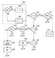
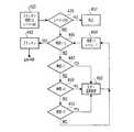
説明用の例として、図12A及び図12Bに、上記の状況1、状況2、及び状況4で述べたように、失速したブラシモータについて脱出行動が必要であることを識別する、好適な実施形態で用いられる、解析を示す。ブラシの電流がブラシモータの所与のリミット値を超える(ステップ402)度に、率レジスタが1づつインクリメントされる(ステップ404)。一方、リミット値に達しなければ、率レジスタは1づつデクリメントされる(ステップ406)。個々の変化率レジスタは、間近の期間、例えば120サイクル、での直近の値を格納する。失速率が600(600は、1秒間の一定の失速に対応する)を超えていて(ステップ414)、変化率が正である(ステップ416)場合、脱出行動の実行が許容(ステップ418)であれば、ロボットは脱出行動を実行する(ステップ420)。実行後、失速率が0に戻るまで(ステップ422)脱出行動は禁止され(ステップ428)、再び許容され(ステップ424)、そして再度600に上昇する。これは、失速率が600を超えていると常に脱出行動が起動されてしまうということを、防止するためになされる。 As an illustrative example, as described in
しかしながら、失速率が2400を超え(ステップ410)、変化率が正であると(ステップ412)、ロボットは、図12Bに示すように、脱出行動の特殊な組を実行することになる。好適な実施形態では、ブラシモータが停止され(ステップ430)、「レベル」が所定量(50〜90)だけインクリメントされ(ステップ430)、失速時間が設定され(ステップ430)、ブラシが停止されてから、パニック行動(ステップ452)は1秒(ステップ445)、4秒(ステップ450)、および7秒(ステップ455)経過時に実行される。そして、制御システムは、ブラシを13秒経過後に再起動する(ステップ440,442)。レベルは、毎秒1ずつデクリメントされてゆく(ステップ444)。レベルが最大の閾値に達すると(ステップ435)、ロボットは全ての動作を停止する(ステップ437)。また、ある種の失速が検出されると、ロボットは、モータの損傷を防ぐためにモータの電圧を制限する等の追加の動作を行う。 However, if the stall rate exceeds 2400 (step 410) and the rate of change is positive (step 412), the robot will execute a special set of escape behaviors, as shown in FIG. 12B. In the preferred embodiment, the brush motor is stopped (step 430), the "level" is incremented by a predetermined amount (50-90) (step 430), the stall time is set (step 430) and the brush is stopped Then, the panic action (step 452) is executed when one second (step 445), four seconds (step 450), and seven seconds (step 455) have elapsed. Then, the control system restarts the brush after 13 seconds (
ロボットの好適な実施形態は、4つの脱出行動を有する。すなわち、回転(TURN)、縁端(EDGE)、脱輪(WHEEL DROP)及び低速度(SLOW)である。 The preferred embodiment of the robot has four escape behaviors. Namely, TURN, EDGE, WHEEL DROP and SLOW.
〔回転(TURN)〕ロボットは、その場でランダムな方向へと回転する。なお、この回転は、高速(通常の回転速度の約2倍)で開始し、減速して、低速(通常の回転速度の約1/2)に達する。速度を変化させることにより、ロボットが様々な状況から脱出するのを助けられることがある。ロボットが回転すべき角度は、ランダムであってもよく、脱出の必要性の度合いの関数であってもよく、これらの双方であってもよい。好適な実施形態においては、パニック度の低い状況では、ロボットは45°〜90°のどこかまで回転し、パニック度の高い状況では、ロボットは90°〜270°のどこかまで回転する。 [TURN] The robot rotates in a random direction on the spot. Note that this rotation starts at a high speed (about twice the normal rotation speed) and decelerates to reach a low speed (about half the normal rotation speed). Varying the speed may help the robot escape from various situations. The angle at which the robot should rotate may be random, may be a function of the degree of need for escape, or both. In a preferred embodiment, in a low panic situation, the robot rotates somewhere between 45 ° and 90 °, and in a high panic situation, the robot rotates somewhere between 90 ° and 270 °.
〔縁端(EDGE)〕ロボットは、(a)衝突せずに60°回転するか、(b)縁端(EDGE)行動が開始されてから回転し、累積角度が170°を超えまで、衝突センサを用いて縁端を辿って行く。縁端(EDGE)行動は、平均の衝突距離が短い(但しパニック行動を起こす程には短くない)ときに有用になることがある。縁端(EDGE)行動により、ロボットは、該ロボットにとって物理的に可能な最も小さな開口をすり抜けることが可能となり、それで、ロボットは移動を制限された領域から脱出できる。 [EDGE] The robot either rotates (a) 60 degrees without collision, or (b) rotates after the EDGE action is initiated, until the cumulative angle exceeds 170 degrees. Follow the edge with the sensor. EDGE behavior may be useful when the average collision distance is short (but not so short as to cause panic behavior). Edge (EDGE) behavior allows the robot to slip through the smallest opening physically possible for the robot so that it can escape movement out of a restricted area.
〔脱輪(WHEEL DROP)〕ロボットは車輪を短時間逆方向に駆動してから、停止させる。車輪の逆方向の駆動は、車輪を反対側に少しだけ突き動かすことにより、本当は脱輪ではないのに誤って脱輪と判定される可能性を最小限とするのに役立つ。脱輪が2秒以内に解消すると、ロボットは通常の動作を継続する。 [WHEEL DROP] The robot drives the wheels in the reverse direction for a short time and then stops. Driving the wheels in the reverse direction helps to minimize the possibility of falsely derailed wheels, which are not really derailed, by pushing the wheels a little against the other side. The robot continues its normal operation when the derailing disappears within 2 seconds.
〔低速度(SLOW)〕脱輪又は絶壁検出器がオフになると、ロボットは、0.5mの距離に亘って速度を0.235m/s(すなわち通常速度の77%)まで落としてから、通常の速度に復帰する。 [SLOW] When the wheel removal or cliff detector is turned off, the robot reduces the speed to 0.235 m / s (ie 77% of the normal speed) over a distance of 0.5 m before To the speed of
カバー(coverage)行動及び脱出行動に加えて、ロボットは、安全性や有用性に関する追加の動作を含んでいてもよい。例えば、所定時間を超えて絶壁が検出され続けた場合、ロボットは停止する。絶壁が最初に検出されたとき、絶壁回避反応行動が、直ちに、あらゆる他の行動に対して優先し、ロボットが絶壁を検出しなくなるまで、該ロボットを絶壁から離れるように回転させる。好適な実施形態では、絶壁検出事象によっては、動作モードは変わらない。他の実施形態では、ロボットは、壁面追従行動に類似したアルゴリズムを用いて、絶壁の追従が可能であってもよい。 In addition to coverage and escape behavior, the robot may include additional actions regarding safety and usefulness. For example, if a cliff continues to be detected after a predetermined time, the robot stops. When a cliff is first detected, the cliff avoidance response action immediately takes precedence over any other actions, causing the robot to rotate away from the cliff until the robot no longer detects the cliff. In the preferred embodiment, the bluff detection event does not change the operating mode. In another embodiment, the robot may be able to follow the cliff using an algorithm similar to wall-following behavior.
以上、3つの動作モードにおける個々の動作を説明した。次に、我々は、様々なモード間の切替の好適なモードについて説明する。 The individual operations in the three operation modes have been described above. Next we describe the preferred modes of switching between the various modes.
最適なカバー(coverage)及び清掃効率を達成するために、好適な実施形態では、様々なカバー(coverage)動作に優先度を与える制御プログラムが用いられる。(必要であれば、脱出行動に常に高い優先度が与えられる。)例えば、ロボット10は、特定の時間又はランダムな時間、壁面追従モードを用い、その後、動作モードを室内清掃に切り替えてもよい。動作モードを切り替えることにより、本発明のロボット装置は、カバレッジ、清掃効率、及び知覚効率を向上させることができる。 In order to achieve optimal coverage and cleaning efficiency, in a preferred embodiment, a control program is used which gives priority to various coverage operations. (If necessary, the escape action is always given high priority.) For example, the
例として、図13A及び図13Bに、「犬用の骨(ドッグボーン)」形状の環境中の移動ロボット10を示す。この環境では、ほぼ同じ寸法の2つの部屋115,116が、狭い通路105でつながっている。(この例は、先に検討したロボット拡散問題を示している。)この配置は、典型的な室内環境を単純化したものである。ここで、「ドッグボーン」は、室内の障害物の配置により発生していてもよい。図13Aでは、ロボット10がランダムな反跳モードで動作する場合の、ロボット10の通り道が線54として描かれている。ロボット10は、限定された走行を行っている間には、部屋116から部屋115へと移動することができない。なぜなら、ロボットのランダムな行動が起こらず、そのロボットが通路105を通過するように導かれるということが起こらないためである。この方法では、カバレッジが最適なものよりもはるかに狭くなり、ロボット10が自身の経路に何度も交差することで、清掃レートが低下してしまう。 As an example, FIGS. 13A and 13B show the
図13Bに、ロボット10の好適な実施形態の動作を示す。ここで、ロボットは、反跳動作と壁面追従動作とを交互に繰り返す。ロボット10は、経路99を辿りながら、壁100に遭遇するたびに、ロボットの直径の2倍に等しい距離だけ壁面に追従している。経路99において、ロボットが壁面追従モードで動作している部分には、符号51が付されている。この方法により、カバレッジが非常に拡がり、それに伴って、清掃レート及び知覚効率も向上している。 The operation of the preferred embodiment of
最後に、本発明の好適な実施形態を図14に詳細に示す。この図では、全ての動作モードが使用されている。好適な実施形態では、清掃機10は、螺旋モードで始動する(移動線45)。反射螺旋パターンが用いられる場合、清掃機は、所定の回数又はランダムな回数だけ反射事象が起こるまで、螺旋モードを継続する。通常の螺旋が用いられる場合(図14に示すように)、清掃機は、衝突センサの事象が起こるまで継続することになる。好適な実施形態では、きっかけとなる事象が起こると、直ちに、清掃機は壁面追従モードに入る。 Finally, a preferred embodiment of the present invention is shown in detail in FIG. In this figure, all operating modes are used. In the preferred embodiment, the cleaner 10 starts in a spiral mode (moving line 45). If a reflective spiral pattern is used, the cleaner continues the spiral mode until a predetermined or random number of reflection events occur. If a normal spiral is used (as shown in FIG. 14), the cleaner will continue until a crash sensor event occurs. In the preferred embodiment, the cleaner enters wall follow mode as soon as the triggering event occurs.
そして、好適な実施形態では、清掃機は、衝突センサ事象に基づき、あるいは壁面追従アルゴリズムの完了に基づいて、壁面追従モード(移動線51)とランダムな反跳モード(動作線48)との間を切り替える。ある実施形態では、清掃機は、螺旋モードには回帰しない。一方、他の実施形態では、清掃機は、所定の事象又はランダムな事象に基づいて、螺旋モードに入ることがある。 And, in the preferred embodiment, the cleaner is between the wall following mode (moving line 51) and the random recoil mode (operating line 48) based on the crash sensor event or based on the completion of the wall following algorithm. Switch. In one embodiment, the cleaner does not revert to the helical mode. On the other hand, in other embodiments, the cleaner may enter a spiral mode based on predetermined or random events.
好適な実施形態では、ロボットは、衝突と衝突との間の平均移動距離を記録し続けている。そして、ロボットは、以下の式:((3/4)×ABD)+((1/4)×(最新の衝突間距離))を用いて、平均衝突距離(ABD)を算出する。ABDが所定の閾値を超えた場合、ロボットは、再び螺旋行動に優先権を与える。さらに別の実施形態では、ロボットは、螺旋駆動に再び優先権が与えられる前に、最低限の回数の衝突事象をもってもよい。他の実施形態では、ロボットは、例えば20フィートの最大距離を移動した場合に、衝突事象がなくとも、螺旋行動に入ってもよい。 In the preferred embodiment, the robot keeps track of the average distance traveled between collisions. Then, the robot calculates an average collision distance (ABD) using the following equation: ((3/4) × ABD) + ((1/4) × (latest collision distance)). If the ABD exceeds a predetermined threshold, the robot gives priority to the spiraling action again. In yet another embodiment, the robot may have a minimal number of collision events before priority is again given to the helical drive. In another embodiment, the robot may enter a spiraling motion without a collision event when traveling a maximum distance of, for example, 20 feet.
また、ロボットは、全ての動作を停止する状況を有していてもよい。例えば、マニュアルで選択可能な所望の室内の大きさで、最小及び最大走行時間が設定され、最小合計距離が選択される。最小時間及び最小距離に達すると、ロボットは停止する。同様に、最大時間に達するとロボットは停止する。 Also, the robot may have a situation that stops all operations. For example, minimum and maximum travel times are set, and a minimum total distance is selected, with the desired room size that can be manually selected. When the minimum time and distance are reached, the robot stops. Similarly, when the maximum time is reached, the robot stops.
無論、動作モード間の選択のためのマニュアル制御が、用いられてもよい。例えば、動作モードや行動を変更したりこれらに影響を与えたりするために、リモートコントロールが用いられてもよい。同様に、ケースに取付けられたスイッチ自体が、動作モードの設定やモード間の切替に用いられてもよい。例えば、室内の雑然度を設定するスイッチが用いられてもよい。これにより、ロボットにおいて、限定された検出能力で、より適切なカバレッジアルゴリズムが可能となる。 Of course, manual control for selection between operating modes may be used. For example, remote controls may be used to change or affect operational modes or behaviors. Similarly, the switch itself attached to the case may be used to set the operation mode or switch between the modes. For example, a switch for setting the degree of confusion in the room may be used. This enables more appropriate coverage algorithms with limited detection capabilities in the robot.
本発明そのものの一部が、清掃の他にも様々な目的のための自律型車両に用いられてもよいことが、当業者には理解されるであろう。本発明の範囲は、与えられた実施例によってではなく、特許請求の範囲に記載の請求項及びそれの法的に等価なものにより規定されるべきである。 It will be understood by those skilled in the art that parts of the invention itself may be used in autonomous vehicles for various purposes besides cleaning. The scope of the present invention should be defined not by the given embodiments, but by the claims and their legal equivalents.
Claims (15)
Translated fromJapanese前記ロボットを床面上で駆動方向に前進させ、且つ該駆動方向を変更するために該ロボットを回転させる駆動機構と、
前記駆動方向と直交する方向における前記ロボットの第一端側に配置された床清掃部と、
前記駆動方向に関して前記ロボットの前記第一端側に配置された第一衝突センサと、
前記駆動方向に関して前記第一端側の反対側である前記ロボットの第二端側に配置された第二衝突センサと、
前記第一衝突センサ、前記第二衝突センサ、又は該第一衝突センサ及び該第二衝突センサの両方から前記床面に対して鉛直方向に離して配置された第三衝突センサと、
前記ロボットを回転させるよう前記駆動機構を制御する駆動コントローラであって、
前記第一衝突センサ及び前記第二衝突センサの一方又は両方からの検出信号に基づいて、前記ロボットに対する前記床面上にある物体の前記床面に対して水平方向の概算位置を判断し、
前記第三衝突センサからの検出信号並びに前記第一衝突センサ及び前記第二衝突センサの一方又は両方からの検出信号に基づいて、前記ロボットに対する前記物体の前記鉛直方向の概算の接触位置を判断するよう構成され、該判断は、該第三衝突センサからの検出信号の受信と該第一衝突センサ及び該第二衝突センサの一方又は両方からの検出信号の受信との時間差に基づいている、
駆動コントローラと、
を備える移動型ロボット。A mobile robot,
A drive mechanism for advancing the robot in the drive direction on the floor surface and rotating the robot to change the drive direction;
A floor cleaning unit disposed on the first end side of the robot in a direction orthogonal to the driving direction;
A first collision sensor disposed on the first end of the robot with respect to the drive direction;
A second collision sensor disposed on the second end side of the robot opposite to the first end side with respect to the drive direction;
A third collision sensor disposed vertically away from the floor surface from the first collision sensor, the second collision sensor, or both the first collision sensor and the second collision sensor;
A drive controller for controlling the drive mechanism to rotate the robot;
Based on detection signals from one or both of the first collision sensor and the second collision sensor, an approximate horizontal position of the object on the floor surface relative to the floor surface with respect to the robot is determined;
Based on the detection signal from the third collision sensor and the detection signals from one or both of the first collision sensor and the second collision sensor, the approximate verticalcontact position of the object with respect to the robot is determined Configured such that the determination is based on a time difference between receiving a detection signal from the third crash sensor and receiving a detection signal from one or both of the first crash sensor and the second crash sensor.
Drive controller,
Mobile robot equipped with
前記ロボットを床面上で駆動方向に前進させ、且つ該駆動方向を変更するために該ロボットを回転させる駆動機構と、 A drive mechanism for advancing the robot in the drive direction on the floor surface and rotating the robot to change the drive direction;
前記駆動方向と直交する方向における前記ロボットの第一端側に配置された床清掃部と、 A floor cleaning unit disposed on the first end side of the robot in a direction orthogonal to the driving direction;
前記駆動方向に関して前記ロボットの前記第一端側に配置された第一衝突センサと、 A first collision sensor disposed on the first end of the robot with respect to the drive direction;
前記駆動方向に関して前記第一端側の反対側である前記ロボットの第二端側に配置された第二衝突センサと、 A second collision sensor disposed on the second end side of the robot opposite to the first end side with respect to the drive direction;
前記第一衝突センサ及び前記第二衝突センサの両方から前記床面に対して鉛直方向に離して配置された第三衝突センサと、 A third collision sensor disposed vertically away from the floor surface from both the first collision sensor and the second collision sensor;
前記ロボットを回転させるよう前記駆動機構を制御する駆動コントローラであって、前記第一衝突センサ、前記第二衝突センサ及び前記第三衝突センサからの検出信号に基づいて、前記ロボットに対する前記床面上にある物体の三次元における概算の接触角度を判断するよう構成され、該判断は、該第一衝突センサ、該第二衝突センサ及び該第三衝突センサのそれぞれからの検出信号の受信の時間差に基づいている、駆動コントローラと、 A drive controller for controlling the drive mechanism to rotate the robot, wherein the floor surface for the robot is detected based on detection signals from the first collision sensor, the second collision sensor, and the third collision sensor. The apparatus is configured to determine an approximate contact angle in three dimensions of the object at the point in time, wherein the determination is based on the time difference of reception of the detection signal from each of the first collision sensor, the second collision sensor and the third collision sensor. Based on the drive controller,
を備える移動型ロボット。Mobile robot equipped with
前記駆動コントローラは、前記第一端側における物体の接近を前記横側センサを用いて監視しながら該ロボットを回転させて前記床清掃部を該物体に実質隣接するよう配置し、次いで該ロボットを前記駆動方向に駆動させて該第一端側の近傍の該物体を該物体に実質隣接する該床清掃部で追従させるよう構成された、
請求項1又は2に記載の移動型ロボット。The robot further comprises a side sensor arranged to detect the approach of the object at the first end side,
The drive controller rotates the robot while monitoring the approach of the object on the first end side using the side sensor to position the floor cleaning unit substantially adjacent to the object and then the robot The apparatus is configured to be driven in the driving direction to cause the object near the first end to follow the floor cleaning unit substantially adjacent to the object.
Mobile robot according to claim 1or 2.
請求項1又は2に記載の移動型ロボット。One or more of the first collision sensor, the second collision sensor, and the third collision sensor may include a contact sensor configured to detect contact with an obstacle.
Mobile robot according to claim 1or 2.
請求項4に記載の移動型ロボット。The contact sensor comprises a capacitive sensor or a mechanical switch
The mobile robot according to claim4 .
前記第一衝突センサ、前記第二衝突センサ及び前記第三衝突センサのうちの一つ以上からの検出信号に基づいて、前記ロボットが障害物に接触している接触期間を判断し、
前記接触期間が所定時間より長い場合に前記ロボットの電源を落とすよう構成された、
請求項1又は2に記載の移動型ロボット。The drive controller further comprises:
The contact period in which the robot is in contact with an obstacle is determined based on detection signals from one or more of the first collision sensor, the second collision sensor, and the third collision sensor,
Configured to power off the robot if the contact period is longer than a predetermined time,
Mobile robot according to claim 1or 2.
前記駆動コントローラは、前記ロングレンジ障害物回避センサで障害物を検出したことに応答して、前記ロボットが該障害物との接触を回避するよう該ロボットの前記駆動機構を制御して曲線の軌道で表面領域をカバーさせる、
請求項1又は2に記載の移動型ロボット。Further equipped with a long range obstacle avoidance sensor,
The drive controller controls the drive mechanism of the robot such that the robot avoids contact with the obstacle in response to detection of the obstacle by the long range obstacle avoidance sensor, and the trajectory of the curve Cover the surface area with
Mobile robot according to claim 1or 2.
前記第一衝突センサ、前記第二衝突センサ及び前記横側センサは壁に応答するものであり、
前記駆動コントローラは、壁を検出したことに応答して、該壁が前記ロボットの前記第一端側で検出されるまで該ロボットを回転させ、次いで該壁を該ロボットの該第一端側に維持するよう該ロボットを駆動する、
請求項7に記載の移動型ロボット。The robot further comprises a side sensor arranged to detect the approach of the object at the first end side,
The first collision sensor, the second collision sensor and the side sensor are responsive to a wall,
The drive controller, in response to detecting a wall, causes the robot to rotate until the wall is detected at the first end of the robot, and then the wall to the first end of the robot Drive the robot to maintain,
The mobile robot according to claim7 .
請求項1又は2に記載の移動型ロボット。The floor cleaning unit includes a side brush,
Mobile robot according to claim 1or 2.
請求項1又は2に記載の移動型ロボット。The drive controller determines that a specific object is no longer in the vicinity of the first end of the robot when the lateral sensor transitions from a reflective state to a non-reflective state.
Mobile robot according to claim 1or 2.
請求項1又は2に記載の移動型ロボット。The drive controller is configured to drive the robot such that the robot rotates in a trajectory of a spiral of increasing radius so that the first end of the robot is located at the outer end of the spiral.
Mobile robot according to claim 1or 2.
前記駆動コントローラは、前記ロボットが該ロボットの前記第一端側の物体に追従している間に該ロボットが前記駆動方向にある物体に衝突したことに応答して、該ロボットが該衝突した物体に沿って移動するよう、該ロボットの該第一端側から離れる方向に該ロボットを第一角度回転させ、前記横側センサが該衝突した物体を検出したら回転を停止させ、次いで該ロボットを前記駆動方向に前進駆動させる、
請求項1又は2に記載の移動型ロボット。The robot further comprises a side sensor arranged to detect the approach of the object at the first end side,
The drive controller is responsive to the robot colliding with an object in the drive direction while the robot is following an object on the first end side of the robot. The robot is rotated by a first angle in a direction away from the first end of the robot to move along, the rotation is stopped when the side sensor detects the colliding object, and then the robot is Drive forward in drive direction,
Mobile robot according to claim 1or 2.
請求項12に記載の移動型ロボット。The drive controller stops rotation of the robot in response to rotating the robot by an angle larger than the first angle in a direction away from the first end of the robot, and then drives the robot. Drive forward in the direction.
A mobile robot according to claim12 .
前記第一衝突センサからの検出信号の受信と前記第二衝突センサからの検出信号の受信との間の時間が第一長さの場合は第一回転角度だけロボットを回転させ、該第一衝突センサからの検出信号の受信と該第二衝突センサからの検出信号の受信との間の時間が第二長さの場合、第二回転角度だけロボットを回転させるよう構成され、
前記第一長さは前記第二長さより短く、前記第一回転角度は前記第二回転角度より大きい、
請求項1又は2に記載の移動型ロボット。The drive controller is
If the time between the reception of the detection signal from the first collision sensor and the reception of the detection signal from the second collision sensor is a first length, the robot is rotated by a first rotation angle, and the first collision is generated. Configured to rotate the robot by a second rotation angle if the time between the reception of the detection signal from the sensor and the reception of the detection signal from the second collision sensor is a second length,
The first length is shorter than the second length, and the first rotation angle is larger than the second rotation angle.
Mobile robot according to claim 1or 2.
前記第一衝突センサ、前記第二衝突センサ及び前記第三衝突センサのうちの一つ以上からの検出信号に基づいて、前記ロボットが障害物に接触している接触期間を判断し、
前記接触期間が所定時間より長い場合に前記ロボットを回転させるよう構成された、
請求項1又は2に記載の移動型ロボット。The drive controller further comprises:
The contact period in which the robot is in contact with an obstacle is determined based on detection signals from one or more of the first collision sensor, the second collision sensor, and the third collision sensor,
Configured to rotate the robot if the contact period is longer than a predetermined time,
Mobile robot according to claim 1or 2.
Applications Claiming Priority (2)
| Application Number | Priority Date | Filing Date | Title |
|---|---|---|---|
| US29771801P | 2001-06-12 | 2001-06-12 | |
| US60/297,718 | 2001-06-12 |
Related Parent Applications (1)
| Application Number | Title | Priority Date | Filing Date |
|---|---|---|---|
| JP2015111823ADivisionJP6429728B2 (en) | 2001-06-12 | 2015-06-02 | Mobile robot |
Publications (3)
| Publication Number | Publication Date |
|---|---|
| JP2017054559A JP2017054559A (en) | 2017-03-16 |
| JP2017054559A5 JP2017054559A5 (en) | 2017-11-16 |
| JP6522577B2true JP6522577B2 (en) | 2019-05-29 |
Family
ID=23147452
Family Applications (13)
| Application Number | Title | Priority Date | Filing Date |
|---|---|---|---|
| JP2003504174APendingJP2004522231A (en) | 2001-06-12 | 2002-06-12 | Multi-mode processing method and system for autonomous robot |
| JP2006135862AWithdrawnJP2006318483A (en) | 2001-06-12 | 2006-05-15 | Multi-mode processing method and system for autonomous robot |
| JP2006165217AWithdrawnJP2006331434A (en) | 2001-06-12 | 2006-06-14 | Autonomous robot |
| JP2006336042AWithdrawnJP2007133891A (en) | 2001-06-12 | 2006-12-13 | Method and system for multi-mode coverage for autonomous robot |
| JP2008246310APendingJP2009099137A (en) | 2001-06-12 | 2008-09-25 | Multimode processing method and system for autonomous robot |
| JP2011050428APendingJP2011129155A (en) | 2001-06-12 | 2011-03-08 | Mobile robot cleaner |
| JP2011272048ACeasedJP2012064240A (en) | 2001-06-12 | 2011-12-13 | Mobile robot cleaner |
| JP2013107036AExpired - Fee RelatedJP5767275B2 (en) | 2001-06-12 | 2013-05-21 | Mobile robot cleaner |
| JP2013266238AExpired - LifetimeJP6373000B2 (en) | 2001-06-12 | 2013-12-25 | Mobile cleaning robot |
| JP2014100216APendingJP2014186742A (en) | 2001-06-12 | 2014-05-14 | Mobile robot cleaner |
| JP2015111823AExpired - Fee RelatedJP6429728B2 (en) | 2001-06-12 | 2015-06-02 | Mobile robot |
| JP2015245807AExpired - Fee RelatedJP6250018B2 (en) | 2001-06-12 | 2015-12-17 | Mobile robot cleaner |
| JP2016249208AExpired - Fee RelatedJP6522577B2 (en) | 2001-06-12 | 2016-12-22 | Mobile robot cleaner |
Family Applications Before (12)
| Application Number | Title | Priority Date | Filing Date |
|---|---|---|---|
| JP2003504174APendingJP2004522231A (en) | 2001-06-12 | 2002-06-12 | Multi-mode processing method and system for autonomous robot |
| JP2006135862AWithdrawnJP2006318483A (en) | 2001-06-12 | 2006-05-15 | Multi-mode processing method and system for autonomous robot |
| JP2006165217AWithdrawnJP2006331434A (en) | 2001-06-12 | 2006-06-14 | Autonomous robot |
| JP2006336042AWithdrawnJP2007133891A (en) | 2001-06-12 | 2006-12-13 | Method and system for multi-mode coverage for autonomous robot |
| JP2008246310APendingJP2009099137A (en) | 2001-06-12 | 2008-09-25 | Multimode processing method and system for autonomous robot |
| JP2011050428APendingJP2011129155A (en) | 2001-06-12 | 2011-03-08 | Mobile robot cleaner |
| JP2011272048ACeasedJP2012064240A (en) | 2001-06-12 | 2011-12-13 | Mobile robot cleaner |
| JP2013107036AExpired - Fee RelatedJP5767275B2 (en) | 2001-06-12 | 2013-05-21 | Mobile robot cleaner |
| JP2013266238AExpired - LifetimeJP6373000B2 (en) | 2001-06-12 | 2013-12-25 | Mobile cleaning robot |
| JP2014100216APendingJP2014186742A (en) | 2001-06-12 | 2014-05-14 | Mobile robot cleaner |
| JP2015111823AExpired - Fee RelatedJP6429728B2 (en) | 2001-06-12 | 2015-06-02 | Mobile robot |
| JP2015245807AExpired - Fee RelatedJP6250018B2 (en) | 2001-06-12 | 2015-12-17 | Mobile robot cleaner |
Country Status (8)
| Country | Link |
|---|---|
| US (2) | US6809490B2 (en) |
| EP (8) | EP1395888B1 (en) |
| JP (13) | JP2004522231A (en) |
| AT (1) | ATE510247T1 (en) |
| AU (1) | AU2002306142A1 (en) |
| CA (1) | CA2416621C (en) |
| ES (6) | ES2660836T3 (en) |
| WO (1) | WO2002101477A2 (en) |
Families Citing this family (359)
| Publication number | Priority date | Publication date | Assignee | Title |
|---|---|---|---|---|
| US7155308B2 (en) | 2000-01-24 | 2006-12-26 | Irobot Corporation | Robot obstacle detection system |
| US8412377B2 (en)* | 2000-01-24 | 2013-04-02 | Irobot Corporation | Obstacle following sensor scheme for a mobile robot |
| US8788092B2 (en)* | 2000-01-24 | 2014-07-22 | Irobot Corporation | Obstacle following sensor scheme for a mobile robot |
| US6956348B2 (en) | 2004-01-28 | 2005-10-18 | Irobot Corporation | Debris sensor for cleaning apparatus |
| AUPR154400A0 (en)* | 2000-11-17 | 2000-12-14 | Duplex Cleaning Machines Pty. Limited | Robot machine |
| US6883201B2 (en) | 2002-01-03 | 2005-04-26 | Irobot Corporation | Autonomous floor-cleaning robot |
| US7571511B2 (en) | 2002-01-03 | 2009-08-11 | Irobot Corporation | Autonomous floor-cleaning robot |
| US6690134B1 (en)* | 2001-01-24 | 2004-02-10 | Irobot Corporation | Method and system for robot localization and confinement |
| US20020138246A1 (en)* | 2001-03-08 | 2002-09-26 | Czora Gregory J. | System and method for simulating conciousness |
| US7429843B2 (en) | 2001-06-12 | 2008-09-30 | Irobot Corporation | Method and system for multi-mode coverage for an autonomous robot |
| US8396592B2 (en) | 2001-06-12 | 2013-03-12 | Irobot Corporation | Method and system for multi-mode coverage for an autonomous robot |
| KR100420171B1 (en)* | 2001-08-07 | 2004-03-02 | 삼성광주전자 주식회사 | Robot cleaner and system therewith and method of driving thereof |
| IL145680A0 (en) | 2001-09-26 | 2002-06-30 | Friendly Robotics Ltd | Robotic vacuum cleaner |
| EP1441632B1 (en)* | 2001-09-26 | 2013-05-01 | F. Robotics Acquisitions Ltd. | Robotic vacuum cleaner |
| DE10150423A1 (en)* | 2001-10-11 | 2003-04-30 | Siemens Ag | Method and arrangement as well as computer program with program code means and computer program product for assigning a partial area of a total area divided into several partial areas to one of several mobile units |
| US9128486B2 (en) | 2002-01-24 | 2015-09-08 | Irobot Corporation | Navigational control system for a robotic device |
| AU2003256435A1 (en)* | 2002-08-16 | 2004-03-03 | Evolution Robotics, Inc. | Systems and methods for the automated sensing of motion in a mobile robot using visual data |
| US8386081B2 (en) | 2002-09-13 | 2013-02-26 | Irobot Corporation | Navigational control system for a robotic device |
| ES2674568T3 (en)* | 2002-09-13 | 2018-07-02 | Irobot Corporation | Navigation control system for a robotic device |
| US8428778B2 (en) | 2002-09-13 | 2013-04-23 | Irobot Corporation | Navigational control system for a robotic device |
| US7162338B2 (en) | 2002-12-17 | 2007-01-09 | Evolution Robotics, Inc. | Systems and methods for computing a relative pose for global localization in a visual simultaneous localization and mapping system |
| KR100561855B1 (en) | 2002-12-30 | 2006-03-16 | 삼성전자주식회사 | Robot localization system |
| GB2398394B (en)* | 2003-02-14 | 2006-05-17 | Dyson Ltd | An autonomous machine |
| US7805220B2 (en) | 2003-03-14 | 2010-09-28 | Sharper Image Acquisition Llc | Robot vacuum with internal mapping system |
| US20040244138A1 (en)* | 2003-03-14 | 2004-12-09 | Taylor Charles E. | Robot vacuum |
| JP2004275468A (en)* | 2003-03-17 | 2004-10-07 | Hitachi Home & Life Solutions Inc | Self-propelled vacuum cleaner and operating method thereof |
| US7228214B2 (en)* | 2003-03-31 | 2007-06-05 | Deere & Company | Path planner and method for planning a path plan having a spiral component |
| KR100486737B1 (en)* | 2003-04-08 | 2005-05-03 | 삼성전자주식회사 | Method and apparatus for generating and tracing cleaning trajectory for home cleaning robot |
| US7170252B2 (en)* | 2003-07-23 | 2007-01-30 | Renesas Technology Corporation | Location aware automata |
| AU2004202834B2 (en)* | 2003-07-24 | 2006-02-23 | Samsung Gwangju Electronics Co., Ltd. | Robot Cleaner |
| US20050079113A1 (en)* | 2003-10-09 | 2005-04-14 | Selander Raymond K. | Fan-driven air freshener |
| US20050108504A1 (en)* | 2003-10-20 | 2005-05-19 | Cowin Gregory L. | Behavior agent based system and process for machine to machine applications and services |
| DE10357636B4 (en)* | 2003-12-10 | 2013-05-08 | Vorwerk & Co. Interholding Gmbh | Automatically movable floor dust collecting device |
| US7332890B2 (en)* | 2004-01-21 | 2008-02-19 | Irobot Corporation | Autonomous robot auto-docking and energy management systems and methods |
| DE102004004505B9 (en)* | 2004-01-22 | 2010-08-05 | Alfred Kärcher Gmbh & Co. Kg | Soil cultivation device and method for its control |
| JP2005211462A (en)* | 2004-01-30 | 2005-08-11 | Funai Electric Co Ltd | Self-propelled cleaner |
| EP1719031B1 (en)* | 2004-02-12 | 2016-12-07 | Arçelik Anonim Sirketi | A robot vacuum cleaner and a control method |
| US7689321B2 (en)* | 2004-02-13 | 2010-03-30 | Evolution Robotics, Inc. | Robust sensor fusion for mapping and localization in a simultaneous localization and mapping (SLAM) system |
| US20070023540A1 (en)* | 2004-03-03 | 2007-02-01 | Selander Raymond K | Fragrance Delivery for Multimedia Systems |
| US20060020369A1 (en)* | 2004-03-11 | 2006-01-26 | Taylor Charles E | Robot vacuum cleaner |
| WO2005098476A1 (en) | 2004-03-29 | 2005-10-20 | Evolution Robotics, Inc. | Method and apparatus for position estimation using reflected light sources |
| US7617557B2 (en)* | 2004-04-02 | 2009-11-17 | Royal Appliance Mfg. Co. | Powered cleaning appliance |
| SG174000A1 (en) | 2004-06-24 | 2011-09-29 | Irobot Corp | Remote control scheduler and method for autonomous robotic device |
| US8972052B2 (en) | 2004-07-07 | 2015-03-03 | Irobot Corporation | Celestial navigation system for an autonomous vehicle |
| US7706917B1 (en) | 2004-07-07 | 2010-04-27 | Irobot Corporation | Celestial navigation system for an autonomous robot |
| US11209833B2 (en) | 2004-07-07 | 2021-12-28 | Irobot Corporation | Celestial navigation system for an autonomous vehicle |
| KR100595571B1 (en)* | 2004-09-13 | 2006-07-03 | 엘지전자 주식회사 | robotic vacuum |
| US20060059880A1 (en)* | 2004-09-13 | 2006-03-23 | Angott Paul G | Unmanned utility vehicle |
| JP2006085369A (en)* | 2004-09-15 | 2006-03-30 | Sony Corp | Traveling object device and its control method |
| US8000837B2 (en)* | 2004-10-05 | 2011-08-16 | J&L Group International, Llc | Programmable load forming system, components thereof, and methods of use |
| AU2005309571A1 (en)* | 2004-11-23 | 2006-06-01 | S. C. Johnson & Son, Inc. | Device and methods of providing air purification in combination with cleaning of surfaces |
| KR20060059006A (en)* | 2004-11-26 | 2006-06-01 | 삼성전자주식회사 | METHOD AND APPARATUS FOR MOBILE APPLIANCES TO MOVE ACCIDENTS WITH HIDENTS |
| US7620476B2 (en) | 2005-02-18 | 2009-11-17 | Irobot Corporation | Autonomous surface cleaning robot for dry cleaning |
| KR101240732B1 (en) | 2005-02-18 | 2013-03-07 | 아이로보트 코퍼레이션 | Autonomous surface cleaning robot for wet and dry cleaning |
| US8392021B2 (en) | 2005-02-18 | 2013-03-05 | Irobot Corporation | Autonomous surface cleaning robot for wet cleaning |
| US7389156B2 (en)* | 2005-02-18 | 2008-06-17 | Irobot Corporation | Autonomous surface cleaning robot for wet and dry cleaning |
| KR100633444B1 (en)* | 2005-02-24 | 2006-10-13 | 삼성광주전자 주식회사 | Robot cleaner and its control method |
| KR100633446B1 (en)* | 2005-02-24 | 2006-10-13 | 삼성광주전자 주식회사 | Mobile robot with humidifier |
| KR100654676B1 (en)* | 2005-03-07 | 2006-12-08 | 삼성광주전자 주식회사 | robotic vacuum |
| US20060216193A1 (en)* | 2005-03-22 | 2006-09-28 | Johnson Kaj A | Cleaning tools with UV flash unit |
| US8930023B2 (en) | 2009-11-06 | 2015-01-06 | Irobot Corporation | Localization by learning of wave-signal distributions |
| JP2006271807A (en)* | 2005-03-30 | 2006-10-12 | Toshiba Tec Corp | Traveling work robot |
| KR100638219B1 (en)* | 2005-04-23 | 2006-10-27 | 엘지전자 주식회사 | Robot vacuum cleaner driving method |
| KR100635827B1 (en)* | 2005-04-25 | 2006-10-19 | 엘지전자 주식회사 | Cleaning Robot with Depression Detection Method and Method |
| KR100669892B1 (en)* | 2005-05-11 | 2007-01-19 | 엘지전자 주식회사 | Mobile robot with obstacle avoidance and method |
| US7877166B2 (en) | 2005-06-28 | 2011-01-25 | S.C. Johnson & Son, Inc. | RFID navigational system for robotic floor treater |
| US7389166B2 (en)* | 2005-06-28 | 2008-06-17 | S.C. Johnson & Son, Inc. | Methods to prevent wheel slip in an autonomous floor cleaner |
| US7578020B2 (en)* | 2005-06-28 | 2009-08-25 | S.C. Johnson & Son, Inc. | Surface treating device with top load cartridge-based cleaning system |
| CN101253299B (en)* | 2005-07-20 | 2013-03-06 | 欧普帝姆斯特许股份公司 | Re-design of hospital operating room |
| JP2007030060A (en)* | 2005-07-22 | 2007-02-08 | Honda Motor Co Ltd | Mobile robot controller |
| US7456596B2 (en) | 2005-08-19 | 2008-11-25 | Cisco Technology, Inc. | Automatic radio site survey using a robot |
| CN101297267B (en)* | 2005-09-02 | 2012-01-11 | Neato机器人技术公司 | Multi-function robotic device |
| KR100749579B1 (en)* | 2005-09-05 | 2007-08-16 | 삼성광주전자 주식회사 | Mobile robot system having a plurality of replaceable work modules and control method thereof |
| US9144360B2 (en) | 2005-12-02 | 2015-09-29 | Irobot Corporation | Autonomous coverage robot navigation system |
| EP2270619B1 (en) | 2005-12-02 | 2013-05-08 | iRobot Corporation | Modular robot |
| KR101290379B1 (en) | 2005-12-02 | 2013-07-26 | 아이로보트 코퍼레이션 | Autonomous coverage robot navigation system |
| JP4875102B2 (en) | 2005-12-02 | 2012-02-15 | アイロボット コーポレイション | Coverage robot mobility |
| EP2816434A3 (en) | 2005-12-02 | 2015-01-28 | iRobot Corporation | Autonomous coverage robot |
| KR101099808B1 (en) | 2005-12-02 | 2011-12-27 | 아이로보트 코퍼레이션 | Robotic systems |
| KR101300492B1 (en) | 2005-12-02 | 2013-09-02 | 아이로보트 코퍼레이션 | Coverage robot mobility |
| US7327112B1 (en)* | 2006-03-06 | 2008-02-05 | Adrian Gregory Hlynka | Multiple leg tumbling robot |
| EP3067771B1 (en) | 2006-03-17 | 2017-11-08 | iRobot Corporation | Robot confinement |
| KR100772907B1 (en)* | 2006-05-01 | 2007-11-05 | 삼성전자주식회사 | Robot with Obstacle Sensing Function and its Control Method |
| US8326469B2 (en)* | 2006-07-14 | 2012-12-04 | Irobot Corporation | Autonomous behaviors for a remote vehicle |
| US8108092B2 (en) | 2006-07-14 | 2012-01-31 | Irobot Corporation | Autonomous behaviors for a remote vehicle |
| KR100772912B1 (en)* | 2006-05-16 | 2007-11-05 | 삼성전자주식회사 | Robot using absolute azimuth and map creation method using same |
| US20090044370A1 (en) | 2006-05-19 | 2009-02-19 | Irobot Corporation | Removing debris from cleaning robots |
| US8417383B2 (en) | 2006-05-31 | 2013-04-09 | Irobot Corporation | Detecting robot stasis |
| WO2007143756A2 (en)* | 2006-06-09 | 2007-12-13 | Carnegie Mellon University | System and method for autonomously convoying vehicles |
| US8355818B2 (en)* | 2009-09-03 | 2013-01-15 | Battelle Energy Alliance, Llc | Robots, systems, and methods for hazard evaluation and visualization |
| US8271132B2 (en)* | 2008-03-13 | 2012-09-18 | Battelle Energy Alliance, Llc | System and method for seamless task-directed autonomy for robots |
| US7668621B2 (en)* | 2006-07-05 | 2010-02-23 | The United States Of America As Represented By The United States Department Of Energy | Robotic guarded motion system and method |
| US7587260B2 (en)* | 2006-07-05 | 2009-09-08 | Battelle Energy Alliance, Llc | Autonomous navigation system and method |
| US7620477B2 (en)* | 2006-07-05 | 2009-11-17 | Battelle Energy Alliance, Llc | Robotic intelligence kernel |
| US7974738B2 (en)* | 2006-07-05 | 2011-07-05 | Battelle Energy Alliance, Llc | Robotics virtual rail system and method |
| US8073564B2 (en)* | 2006-07-05 | 2011-12-06 | Battelle Energy Alliance, Llc | Multi-robot control interface |
| US7584020B2 (en)* | 2006-07-05 | 2009-09-01 | Battelle Energy Alliance, Llc | Occupancy change detection system and method |
| US7801644B2 (en)* | 2006-07-05 | 2010-09-21 | Battelle Energy Alliance, Llc | Generic robot architecture |
| US8965578B2 (en) | 2006-07-05 | 2015-02-24 | Battelle Energy Alliance, Llc | Real time explosive hazard information sensing, processing, and communication for autonomous operation |
| US8843244B2 (en)* | 2006-10-06 | 2014-09-23 | Irobot Corporation | Autonomous behaviors for a remove vehicle |
| KR100769909B1 (en)* | 2006-09-06 | 2007-10-24 | 엘지전자 주식회사 | Mobile Robot and Its Operation Method |
| US8196169B1 (en)* | 2006-09-18 | 2012-06-05 | Nvidia Corporation | Coordinate-based set top box policy enforcement system, method and computer program product |
| KR100759919B1 (en)* | 2006-11-28 | 2007-09-18 | 삼성광주전자 주식회사 | Robot cleaner and control method |
| TWI308487B (en)* | 2006-12-26 | 2009-04-11 | Ind Tech Res Inst | Position-detecting system and method |
| US8189107B1 (en) | 2007-03-12 | 2012-05-29 | Nvidia Corporation | System and method for performing visual data post-processing based on information related to frequency response pre-processing |
| JP4512200B2 (en)* | 2007-03-15 | 2010-07-28 | 株式会社日立製作所 | robot |
| US20080229885A1 (en)* | 2007-03-22 | 2008-09-25 | Mah Pat Y | Jar opener |
| KR101281512B1 (en)* | 2007-04-06 | 2013-07-03 | 삼성전자주식회사 | Robot cleaner and control method thereof |
| US8086551B2 (en) | 2007-04-16 | 2011-12-27 | Blue Oak Mountain Technologies, Inc. | Electronic system with simulated sense perception and method of providing simulated sense perception |
| ES2571739T3 (en) | 2007-05-09 | 2016-05-26 | Irobot Corp | Autonomous compact covering robot |
| US8255092B2 (en) | 2007-05-14 | 2012-08-28 | Irobot Corporation | Autonomous behaviors for a remote vehicle |
| KR101361562B1 (en)* | 2007-05-31 | 2014-02-13 | 삼성전자주식회사 | Cleanning robot |
| CN101320420A (en)* | 2007-06-08 | 2008-12-10 | 鹏智科技(深圳)有限公司 | Biology-like system and device, and its action execution method |
| DE102007053311A1 (en)* | 2007-06-21 | 2008-12-24 | Robert Bosch Gmbh | Drive system for a robotic vehicle |
| EP2219506B1 (en)* | 2007-10-30 | 2017-06-21 | LG Electronics Inc. | Detecting apparatus of robot cleaner and controlling method of robot cleaner |
| DE102007059118A1 (en)* | 2007-12-07 | 2009-06-10 | Robert Bosch Gmbh | Autonomous working device |
| KR20090077547A (en)* | 2008-01-11 | 2009-07-15 | 삼성전자주식회사 | Path planning method and device of mobile robot |
| US8838268B2 (en)* | 2008-01-28 | 2014-09-16 | Seegrid Corporation | Service robot and method of operating same |
| EP2249999B1 (en)* | 2008-01-28 | 2013-03-27 | Seegrid Corporation | Methods for repurposing temporal-spatial information collected by service robots |
| US8892256B2 (en)* | 2008-01-28 | 2014-11-18 | Seegrid Corporation | Methods for real-time and near real-time interactions with robots that service a facility |
| US8755936B2 (en)* | 2008-01-28 | 2014-06-17 | Seegrid Corporation | Distributed multi-robot system |
| CN104248395B (en) | 2008-04-24 | 2018-06-22 | 艾罗伯特公司 | The positioning of mobile product, position control and the application of navigation system enabled for robot |
| US8074320B2 (en)* | 2008-05-15 | 2011-12-13 | Rachael Anne Batchelder | Autonomous blower for debris herding |
| DE102008028931A1 (en)* | 2008-06-18 | 2009-12-24 | BSH Bosch und Siemens Hausgeräte GmbH | Robot i.e. dust collecting robot, drive movement controlling method, involves stopping drive movement of robot during determination of coordinate values based on comparison of coordinate values of virtual partial region and/or virtual wall |
| US20100125968A1 (en)* | 2008-11-26 | 2010-05-27 | Howard Ho | Automated apparatus and equipped trashcan |
| US7926598B2 (en) | 2008-12-09 | 2011-04-19 | Irobot Corporation | Mobile robotic vehicle |
| JP5158808B2 (en)* | 2009-02-23 | 2013-03-06 | 独立行政法人科学技術振興機構 | Robot control system and robot control method |
| KR101484940B1 (en)* | 2009-05-14 | 2015-01-22 | 삼성전자 주식회사 | Robot cleaner and its control method |
| TWI388956B (en) | 2009-05-20 | 2013-03-11 | Univ Nat Taiwan Science Tech | Mobile robot, method for planning paths of manipulating target objects thereof |
| US8774970B2 (en) | 2009-06-11 | 2014-07-08 | S.C. Johnson & Son, Inc. | Trainable multi-mode floor cleaning device |
| US9037294B2 (en) | 2009-06-12 | 2015-05-19 | Samsung Electronics Co., Ltd. | Robot cleaner and control method thereof |
| US8428776B2 (en) | 2009-06-18 | 2013-04-23 | Michael Todd Letsky | Method for establishing a desired area of confinement for an autonomous robot and autonomous robot implementing a control system for executing the same |
| IT1395844B1 (en)* | 2009-06-30 | 2012-10-26 | Bernini | LAWNMOWER |
| US8364309B1 (en) | 2009-07-14 | 2013-01-29 | Bailey Bendrix L | User-assisted robot navigation system |
| US8879426B1 (en)* | 2009-09-03 | 2014-11-04 | Lockheed Martin Corporation | Opportunistic connectivity edge detection |
| KR20110054472A (en)* | 2009-11-17 | 2011-05-25 | 엘지전자 주식회사 | Robot cleaner and his control method |
| KR101406186B1 (en)* | 2009-11-18 | 2014-06-13 | 삼성전자주식회사 | Control method of robot cleaner |
| TW201117760A (en)* | 2009-11-25 | 2011-06-01 | Ind Tech Res Inst | Puddle eliminating system and puddle eliminating method |
| WO2011103198A1 (en) | 2010-02-16 | 2011-08-25 | Irobot Corporation | Vacuum brush |
| US9807925B2 (en)* | 2010-07-28 | 2017-11-07 | Deere & Company | Robotic mower area coverage system |
| US20120029752A1 (en)* | 2010-07-28 | 2012-02-02 | Johnson David A | Robotic Mower Stuck Detection System |
| JP5745067B2 (en) | 2010-09-24 | 2015-07-08 | アイロボット・コーポレーション | System and method for VSLAM optimization |
| DE102011003064A1 (en)* | 2010-12-29 | 2012-07-05 | Robert Bosch Gmbh | Method for processing a surface by means of a robot vehicle |
| EP2659323B1 (en) | 2010-12-30 | 2018-06-13 | iRobot Corporation | Coverage robot navigation |
| EP2659260B1 (en) | 2010-12-30 | 2019-11-20 | iRobot Corporation | Debris monitoring |
| US20120167917A1 (en) | 2011-01-03 | 2012-07-05 | Gilbert Jr Duane L | Autonomous coverage robot |
| DE102011006062B4 (en) | 2011-03-24 | 2023-05-25 | RobArt GmbH | Procedure for autonomous inspection of an environment or processing of ground surfaces |
| US11471020B2 (en) | 2011-04-29 | 2022-10-18 | Irobot Corporation | Robotic vacuum cleaning system |
| EP2701570B1 (en) | 2011-04-29 | 2019-02-13 | iRobot Corporation | An autonomous mobile robot |
| US8549826B2 (en) | 2011-07-25 | 2013-10-08 | Deere & Company | Robotic mower launch point system |
| WO2013036284A1 (en) | 2011-09-07 | 2013-03-14 | Irobot Corporation | Sonar system for remote vehicle |
| US8798840B2 (en) | 2011-09-30 | 2014-08-05 | Irobot Corporation | Adaptive mapping with spatial summaries of sensor data |
| US8589013B2 (en) | 2011-10-25 | 2013-11-19 | Jaybridge Robotics, Inc. | Method and system for dynamically positioning a vehicle relative to another vehicle in motion |
| US10476130B2 (en) | 2011-12-05 | 2019-11-12 | Adasa Inc. | Aerial inventory antenna |
| US10050330B2 (en) | 2011-12-05 | 2018-08-14 | Adasa Inc. | Aerial inventory antenna |
| US11093722B2 (en) | 2011-12-05 | 2021-08-17 | Adasa Inc. | Holonomic RFID reader |
| US9780435B2 (en) | 2011-12-05 | 2017-10-03 | Adasa Inc. | Aerial inventory antenna |
| US9747480B2 (en) | 2011-12-05 | 2017-08-29 | Adasa Inc. | RFID and robots for multichannel shopping |
| US10846497B2 (en) | 2011-12-05 | 2020-11-24 | Adasa Inc. | Holonomic RFID reader |
| DE102012201870A1 (en) | 2012-02-08 | 2013-08-08 | RobArt GmbH | Method for automatically triggering a self-localization |
| US8983767B2 (en) | 2012-03-02 | 2015-03-17 | Jaybridge Robotics, Inc. | Computer-implemented method and system for generating swath coverage patterns for polygonal and pseudo-polygonal shaped fields |
| CN107024933B (en) | 2012-03-15 | 2021-07-06 | 艾罗伯特公司 | Buffer for robot including sensor array |
| CN103323002B (en)* | 2012-03-19 | 2016-04-27 | 联想(北京)有限公司 | Instant location and map constructing method and device |
| US9146560B2 (en) | 2012-03-30 | 2015-09-29 | Irobot Corporation | System and method for implementing force field deterrent for robot |
| CN103356122A (en)* | 2012-04-05 | 2013-10-23 | 科沃斯机器人科技(苏州)有限公司 | Glass cleaning device |
| CN103376801B (en)* | 2012-04-13 | 2016-08-03 | 科沃斯机器人有限公司 | From moving land disposal robot and the control method of cleaning thereof |
| US8965623B2 (en)* | 2012-05-11 | 2015-02-24 | International Business Machines Corporation | Automated cleaning in a sensor network |
| KR101954144B1 (en) | 2012-06-08 | 2019-03-05 | 엘지전자 주식회사 | Robot cleaner, controlling method of the same, and robot cleaning system |
| ES2610755T3 (en) | 2012-08-27 | 2017-05-03 | Aktiebolaget Electrolux | Robot positioning system |
| DE102012108802A1 (en)* | 2012-09-19 | 2014-03-20 | Vorwerk & Co. Interholding Gmbh | Automatically movable floor cleaning device and method for operating a floor cleaning device |
| AU2013317738B2 (en) | 2012-09-21 | 2015-05-07 | Irobot Corporation | Proximity sensing on mobile robots |
| DE102012109004A1 (en) | 2012-09-24 | 2014-03-27 | RobArt GmbH | Robots and methods for autonomous inspection or processing of floor surfaces |
| CN103778143B (en)* | 2012-10-22 | 2017-09-01 | 联想(北京)有限公司 | A kind of method, electronic equipment and system for building map |
| TWM451103U (en)* | 2012-10-30 | 2013-04-21 | Agait Technology Corp | Walking device |
| US8972061B2 (en) | 2012-11-02 | 2015-03-03 | Irobot Corporation | Autonomous coverage robot |
| US9020637B2 (en) | 2012-11-02 | 2015-04-28 | Irobot Corporation | Simultaneous localization and mapping for a mobile robot |
| TWI493211B (en)* | 2012-11-02 | 2015-07-21 | Ind Tech Res Inst | Proximity sensing method, proximity sensing apparatus and mobile platform using the same |
| US9282867B2 (en) | 2012-12-28 | 2016-03-15 | Irobot Corporation | Autonomous coverage robot |
| US9178370B2 (en) | 2012-12-28 | 2015-11-03 | Irobot Corporation | Coverage robot docking station |
| US9483055B2 (en) | 2012-12-28 | 2016-11-01 | Irobot Corporation | Autonomous coverage robot |
| EP2946567B1 (en) | 2013-01-18 | 2020-02-26 | iRobot Corporation | Environmental management systems including mobile robots and methods using same |
| US9233472B2 (en) | 2013-01-18 | 2016-01-12 | Irobot Corporation | Mobile robot providing environmental mapping for household environmental control |
| US9375847B2 (en) | 2013-01-18 | 2016-06-28 | Irobot Corporation | Environmental management systems including mobile robots and methods using same |
| US10149430B2 (en)* | 2013-02-20 | 2018-12-11 | Husqvarna Ab | Robotic work tool configured for improved turning in a slope, a robotic work tool system, and a method for use in the robot work tool |
| US9326654B2 (en) | 2013-03-15 | 2016-05-03 | Irobot Corporation | Roller brush for surface cleaning robots |
| US8849494B1 (en) | 2013-03-15 | 2014-09-30 | Google Inc. | Data selection by an autonomous vehicle for trajectory modification |
| US8996224B1 (en) | 2013-03-15 | 2015-03-31 | Google Inc. | Detecting that an autonomous vehicle is in a stuck condition |
| US9008890B1 (en) | 2013-03-15 | 2015-04-14 | Google Inc. | Augmented trajectories for autonomous vehicles |
| KR102020215B1 (en)* | 2013-03-23 | 2019-09-10 | 삼성전자주식회사 | Robot cleaner and method for controlling the same |
| WO2014169943A1 (en) | 2013-04-15 | 2014-10-23 | Aktiebolaget Electrolux | Robotic vacuum cleaner |
| KR102137923B1 (en) | 2013-04-15 | 2020-07-24 | 에이비 엘렉트로룩스 | Robotic vacuum cleaner with protruding sidebrush |
| US9037396B2 (en) | 2013-05-23 | 2015-05-19 | Irobot Corporation | Simultaneous localization and mapping for a mobile robot |
| CN104216404B (en)* | 2013-05-31 | 2017-02-15 | 科沃斯机器人股份有限公司 | Self-moving device and control method thereof |
| KR102083188B1 (en)* | 2013-07-29 | 2020-03-02 | 삼성전자주식회사 | Cleaning robot and method for controlling the same |
| US9188986B2 (en) | 2013-10-01 | 2015-11-17 | Jaybridge Robotics, Inc. | Computer-implemented method and system for dynamically positioning a vehicle relative to another vehicle in motion for on-the-fly offloading operations |
| US9615712B2 (en) | 2013-11-12 | 2017-04-11 | Irobot Corporation | Mobile floor cleaning robot |
| US9233468B2 (en) | 2013-11-12 | 2016-01-12 | Irobot Corporation | Commanding a mobile robot using glyphs |
| EP3069203B1 (en)* | 2013-11-12 | 2020-07-01 | Husqvarna AB | Improved navigation for a robotic working tool |
| US11272822B2 (en) | 2013-11-12 | 2022-03-15 | Irobot Corporation | Mobile floor cleaning robot with pad holder |
| US9427127B2 (en) | 2013-11-12 | 2016-08-30 | Irobot Corporation | Autonomous surface cleaning robot |
| WO2015073521A2 (en)* | 2013-11-18 | 2015-05-21 | New York Institute Of Technology | Motorized walker |
| JP2017503267A (en) | 2013-12-18 | 2017-01-26 | アイロボット コーポレイション | Autonomous mobile robot |
| US10433697B2 (en) | 2013-12-19 | 2019-10-08 | Aktiebolaget Electrolux | Adaptive speed control of rotating side brush |
| WO2015090405A1 (en) | 2013-12-19 | 2015-06-25 | Aktiebolaget Electrolux | Sensing climb of obstacle of a robotic cleaning device |
| CN105793790B (en) | 2013-12-19 | 2022-03-04 | 伊莱克斯公司 | Prioritize cleaning areas |
| US10209080B2 (en) | 2013-12-19 | 2019-02-19 | Aktiebolaget Electrolux | Robotic cleaning device |
| CN105829985B (en) | 2013-12-19 | 2020-04-07 | 伊莱克斯公司 | Robot cleaning device with peripheral recording function |
| KR102116596B1 (en) | 2013-12-19 | 2020-05-28 | 에이비 엘렉트로룩스 | Robotic vacuum cleaner with side brush moving in spiral pattern |
| US10617271B2 (en) | 2013-12-19 | 2020-04-14 | Aktiebolaget Electrolux | Robotic cleaning device and method for landmark recognition |
| WO2015090439A1 (en) | 2013-12-20 | 2015-06-25 | Aktiebolaget Electrolux | Dust container |
| WO2015105712A1 (en) | 2014-01-10 | 2015-07-16 | Irobot Corporation | Autonomous mobile robot |
| EP3126921B1 (en) | 2014-03-31 | 2021-02-24 | iRobot Corporation | Autonomous mobile robot |
| JP6345973B2 (en)* | 2014-04-22 | 2018-06-20 | 東芝ライフスタイル株式会社 | Autonomous vehicle |
| FI126982B (en) | 2014-04-29 | 2017-09-15 | John Deere Forestry Oy | Procedure and system for controlling the crane on a forwarder |
| EP2952300A1 (en)* | 2014-06-05 | 2015-12-09 | Aldebaran Robotics | Collision detection |
| US9168922B1 (en) | 2014-06-05 | 2015-10-27 | Jaybridge Robotics, Inc. | Computer-implemented methods and systems for predicting an area to be traversed by a moving vehicle |
| TW201545699A (en)* | 2014-06-12 | 2015-12-16 | Uni Ring Tech Co Ltd | Traveling method of autonomous cleaning device |
| AU2015285065B2 (en) | 2014-07-01 | 2018-07-05 | Samsung Electronics Co., Ltd. | Cleaning robot and controlling method thereof |
| KR102293615B1 (en)* | 2014-07-02 | 2021-08-26 | 삼성전자주식회사 | Cleaning robot and controlling method thereof |
| CN106415423B (en) | 2014-07-10 | 2021-01-01 | 伊莱克斯公司 | Method for detecting a measurement error of a robotic cleaning device |
| US9764472B1 (en) | 2014-07-18 | 2017-09-19 | Bobsweep Inc. | Methods and systems for automated robotic movement |
| JP6453583B2 (en)* | 2014-08-20 | 2019-01-16 | 東芝ライフスタイル株式会社 | Electric vacuum cleaner |
| JP6494952B2 (en)* | 2014-08-20 | 2019-04-03 | 東芝ライフスタイル株式会社 | Autonomous vehicle |
| JP6325946B2 (en)* | 2014-08-27 | 2018-05-16 | 東芝ライフスタイル株式会社 | Autonomous vehicle |
| JP6517482B2 (en)* | 2014-08-29 | 2019-05-22 | 東芝ライフスタイル株式会社 | Autonomous vehicle and vacuum cleaner |
| DE102014217843A1 (en) | 2014-09-05 | 2016-03-10 | Martin Cudzilo | Apparatus for facilitating the cleaning of surfaces and methods for detecting cleaning work done |
| EP3190938A1 (en) | 2014-09-08 | 2017-07-19 | Aktiebolaget Electrolux | Robotic vacuum cleaner |
| US10499778B2 (en) | 2014-09-08 | 2019-12-10 | Aktiebolaget Electrolux | Robotic vacuum cleaner |
| JP6942102B2 (en)* | 2014-09-09 | 2021-09-29 | シャープ株式会社 | Self-propelled vacuum cleaner |
| JP6397278B2 (en)* | 2014-09-09 | 2018-09-26 | シャープ株式会社 | Self-propelled vacuum cleaner |
| US9798328B2 (en) | 2014-10-10 | 2017-10-24 | Irobot Corporation | Mobile robot area cleaning |
| US9516806B2 (en) | 2014-10-10 | 2016-12-13 | Irobot Corporation | Robotic lawn mowing boundary determination |
| US9510505B2 (en) | 2014-10-10 | 2016-12-06 | Irobot Corporation | Autonomous robot localization |
| US9519289B2 (en) | 2014-11-26 | 2016-12-13 | Irobot Corporation | Systems and methods for performing simultaneous localization and mapping using machine vision systems |
| US9744670B2 (en) | 2014-11-26 | 2017-08-29 | Irobot Corporation | Systems and methods for use of optical odometry sensors in a mobile robot |
| US9751210B2 (en) | 2014-11-26 | 2017-09-05 | Irobot Corporation | Systems and methods for performing occlusion detection |
| US9788698B2 (en) | 2014-12-10 | 2017-10-17 | Irobot Corporation | Debris evacuation for cleaning robots |
| EP3230814B1 (en) | 2014-12-10 | 2021-02-17 | Aktiebolaget Electrolux | Using laser sensor for floor type detection |
| US10568483B2 (en) | 2014-12-12 | 2020-02-25 | Irobot Corporation | Cleaning system for autonomous robot |
| CN107072454A (en) | 2014-12-12 | 2017-08-18 | 伊莱克斯公司 | Side brushes and robot vacuums |
| US9420741B2 (en) | 2014-12-15 | 2016-08-23 | Irobot Corporation | Robot lawnmower mapping |
| US9704043B2 (en) | 2014-12-16 | 2017-07-11 | Irobot Corporation | Systems and methods for capturing images and annotating the captured images with information |
| CN107003669B (en) | 2014-12-16 | 2023-01-31 | 伊莱克斯公司 | Experience-Based Roadmap for Robotic Cleaning Equipment |
| EP3234713B1 (en) | 2014-12-16 | 2022-06-15 | Aktiebolaget Electrolux | Cleaning method for a robotic cleaning device |
| US9538702B2 (en) | 2014-12-22 | 2017-01-10 | Irobot Corporation | Robotic mowing of separated lawn areas |
| CA2972252C (en) | 2014-12-24 | 2023-02-28 | Irobot Corporation | Evacuation station |
| US9757004B2 (en) | 2015-02-12 | 2017-09-12 | Irobot Corporation | Liquid management for floor-traversing robots |
| KR102343100B1 (en) | 2015-02-13 | 2021-12-24 | 삼성전자주식회사 | Cleaning robot and method for controlling the same |
| US9993129B2 (en) | 2015-02-13 | 2018-06-12 | Irobot Corporation | Mobile floor-cleaning robot with floor-type detection |
| US9937628B2 (en)* | 2015-03-03 | 2018-04-10 | The Procter & Gamble Company | Safety device for a mechanical motion device |
| USD774263S1 (en) | 2015-03-03 | 2016-12-13 | Irobot Corporation | Floor cleaning roller core |
| US9907449B2 (en)* | 2015-03-16 | 2018-03-06 | Irobot Corporation | Autonomous floor cleaning with a removable pad |
| US9265396B1 (en) | 2015-03-16 | 2016-02-23 | Irobot Corporation | Autonomous floor cleaning with removable pad |
| JP6735066B2 (en)* | 2015-03-17 | 2020-08-05 | シャープ株式会社 | Self-propelled electronic device |
| US9630319B2 (en) | 2015-03-18 | 2017-04-25 | Irobot Corporation | Localization and mapping using physical features |
| US9868211B2 (en) | 2015-04-09 | 2018-01-16 | Irobot Corporation | Restricting movement of a mobile robot |
| US9918605B2 (en) | 2015-04-09 | 2018-03-20 | Irobot Corporation | Wall following robot |
| US11099554B2 (en) | 2015-04-17 | 2021-08-24 | Aktiebolaget Electrolux | Robotic cleaning device and a method of controlling the robotic cleaning device |
| JP6358393B2 (en)* | 2015-05-08 | 2018-07-18 | 三菱電機株式会社 | Bedding dryer, bedding dryer operation management system and home appliance operation management system |
| JP6525053B2 (en)* | 2015-05-08 | 2019-06-05 | 三菱電機株式会社 | Bedding vacuum cleaner |
| US9505140B1 (en) | 2015-06-02 | 2016-11-29 | Irobot Corporation | Contact sensors for a mobile robot |
| JP6634223B2 (en)* | 2015-06-15 | 2020-01-22 | シャープ株式会社 | Self-propelled electronic device and traveling method of the self-propelled electronic device |
| DE102015109775B3 (en) | 2015-06-18 | 2016-09-22 | RobArt GmbH | Optical triangulation sensor for distance measurement |
| US9462920B1 (en) | 2015-06-25 | 2016-10-11 | Irobot Corporation | Evacuation station |
| DE102015008188B3 (en)* | 2015-06-25 | 2016-06-16 | Kuka Roboter Gmbh | Departure of a predetermined path with a robot |
| US9919425B2 (en) | 2015-07-01 | 2018-03-20 | Irobot Corporation | Robot navigational sensor system |
| US11115798B2 (en) | 2015-07-23 | 2021-09-07 | Irobot Corporation | Pairing a beacon with a mobile robot |
| US10034421B2 (en) | 2015-07-24 | 2018-07-31 | Irobot Corporation | Controlling robotic lawnmowers |
| CN106393140A (en)* | 2015-07-30 | 2017-02-15 | 燕成祥 | Robot capable of automatically adjusting action path and method thereof |
| TWI617907B (en)* | 2015-07-30 | 2018-03-11 | Yan cheng xiang | Robot for automatically adjusting moving path and method thereof |
| EP3344104B1 (en) | 2015-09-03 | 2020-12-30 | Aktiebolaget Electrolux | System of robotic cleaning devices |
| DE102015114883A1 (en) | 2015-09-04 | 2017-03-09 | RobArt GmbH | Identification and localization of a base station of an autonomous mobile robot |
| DE102015119501A1 (en) | 2015-11-11 | 2017-05-11 | RobArt GmbH | Subdivision of maps for robot navigation |
| DE102015119865B4 (en) | 2015-11-17 | 2023-12-21 | RobArt GmbH | Robot-assisted processing of a surface using a robot |
| CN106814732A (en)* | 2015-11-27 | 2017-06-09 | 科沃斯机器人股份有限公司 | Self-movement robot and its walking mode conversion method and traveling method |
| CN105527869B (en)* | 2015-12-01 | 2019-03-01 | 纳恩博(北京)科技有限公司 | Smart machine and its intelligent control method |
| DE102015121666B3 (en) | 2015-12-11 | 2017-05-24 | RobArt GmbH | Remote control of a mobile, autonomous robot |
| JP7036531B2 (en)* | 2016-01-08 | 2022-03-15 | 東芝ライフスタイル株式会社 | Autonomous vehicle |
| US10471611B2 (en) | 2016-01-15 | 2019-11-12 | Irobot Corporation | Autonomous monitoring robot systems |
| US10021830B2 (en) | 2016-02-02 | 2018-07-17 | Irobot Corporation | Blade assembly for a grass cutting mobile robot |
| JP2017140350A (en)* | 2016-02-05 | 2017-08-17 | パナソニックIpマネジメント株式会社 | Autonomous travel-type vacuum cleaner, auxiliary brush for the same and vacuum cleaner system including autonomous travel-type vacuum cleaner |
| WO2017134705A1 (en)* | 2016-02-05 | 2017-08-10 | パナソニックIpマネジメント株式会社 | Autonomous cleaner, auxiliary brush therefor, and cleaner system equipped with autonomous cleaner |
| DE102016102644A1 (en) | 2016-02-15 | 2017-08-17 | RobArt GmbH | Method for controlling an autonomous mobile robot |
| US10459063B2 (en) | 2016-02-16 | 2019-10-29 | Irobot Corporation | Ranging and angle of arrival antenna system for a mobile robot |
| WO2017157421A1 (en) | 2016-03-15 | 2017-09-21 | Aktiebolaget Electrolux | Robotic cleaning device and a method at the robotic cleaning device of performing cliff detection |
| EP3223099B1 (en) | 2016-03-23 | 2021-09-15 | Advanced Digital Broadcast S.A. | System and method for an autonomous cleaning apparatus |
| JP6498627B2 (en)* | 2016-03-31 | 2019-04-10 | 本田技研工業株式会社 | Control device for autonomous vehicle |
| JP6709099B2 (en) | 2016-04-06 | 2020-06-10 | Kyb株式会社 | Shock absorber |
| US11122953B2 (en) | 2016-05-11 | 2021-09-21 | Aktiebolaget Electrolux | Robotic cleaning device |
| CN107398885B (en)* | 2016-05-19 | 2020-11-27 | 科沃斯机器人股份有限公司 | Combined robot |
| AU2017285019B2 (en) | 2016-06-15 | 2022-11-10 | Irobot Corporation | Systems and methods to control an autonomous mobile robot |
| US10575696B2 (en) | 2016-07-13 | 2020-03-03 | Irobot Corporation | Autonomous robot auto-docking and energy management systems and methods |
| JP7073336B2 (en) | 2016-08-05 | 2022-05-23 | ロブアート ゲーエムベーハー | How to control an autonomous mobile robot |
| US9807930B1 (en) | 2016-08-25 | 2017-11-07 | Irobot Corporation | Blade guard for a robot lawnmower |
| EP3512668B1 (en) | 2016-09-14 | 2021-07-21 | iRobot Corporation | Systems and methods for configurable operation of a robot based on area classification |
| EP3298874B1 (en)* | 2016-09-22 | 2020-07-01 | Honda Research Institute Europe GmbH | Robotic gardening device and method for controlling the same |
| US10732127B2 (en)* | 2016-10-26 | 2020-08-04 | Pixart Imaging Inc. | Dirtiness level determining system and surface cleaning machine |
| US10292554B2 (en) | 2016-10-28 | 2019-05-21 | Irobot Corporation | Mobile cleaning robot with a bin |
| EP3335610B1 (en) | 2016-12-14 | 2024-03-06 | Advanced Digital Broadcast S.A. | A surface processing device and a method for processing surface areas |
| US10512384B2 (en) | 2016-12-15 | 2019-12-24 | Irobot Corporation | Cleaning roller for cleaning robots |
| US10456002B2 (en) | 2016-12-22 | 2019-10-29 | Irobot Corporation | Cleaning bin for cleaning robot |
| JP6931994B2 (en)* | 2016-12-22 | 2021-09-08 | パナソニック インテレクチュアル プロパティ コーポレーション オブ アメリカPanasonic Intellectual Property Corporation of America | Autonomous mobile body, mobile control method and mobile control program |
| JP2018114067A (en)* | 2017-01-17 | 2018-07-26 | シャープ株式会社 | Self-propelled cleaner |
| TWI634403B (en)* | 2017-01-26 | 2018-09-01 | 好樣科技有限公司 | Automatic cleaning machine and control method thereof |
| EP3974934A1 (en) | 2017-03-02 | 2022-03-30 | Robart GmbH | Method for controlling an autonomous mobile robot |
| JP6725745B2 (en)* | 2017-03-15 | 2020-07-22 | 日立オートモティブシステムズ株式会社 | Vehicle control device and vehicle control method |
| DE102017109219A1 (en) | 2017-04-28 | 2018-10-31 | RobArt GmbH | Method for robot navigation |
| US11103113B2 (en) | 2017-05-25 | 2021-08-31 | Irobot Corporation | Brush for autonomous cleaning robot |
| EP3629869B1 (en) | 2017-06-02 | 2023-08-16 | Aktiebolaget Electrolux | Method of detecting a difference in level of a surface in front of a robotic cleaning device |
| US10595698B2 (en) | 2017-06-02 | 2020-03-24 | Irobot Corporation | Cleaning pad for cleaning robot |
| US10100968B1 (en) | 2017-06-12 | 2018-10-16 | Irobot Corporation | Mast systems for autonomous mobile robots |
| US10627828B2 (en)* | 2017-06-30 | 2020-04-21 | Casio Computer Co., Ltd. | Autonomous movement device, autonomous movement method and program recording medium |
| WO2019013989A1 (en) | 2017-07-14 | 2019-01-17 | Irobot Corporation | Blade assembly for a grass cutting mobile robot |
| US10595624B2 (en) | 2017-07-25 | 2020-03-24 | Irobot Corporation | Cleaning roller for cleaning robots |
| US10915114B2 (en)* | 2017-07-27 | 2021-02-09 | AI Incorporated | Method and apparatus for combining data to construct a floor plan |
| US11348269B1 (en)* | 2017-07-27 | 2022-05-31 | AI Incorporated | Method and apparatus for combining data to construct a floor plan |
| CN107368079B (en) | 2017-08-31 | 2019-09-06 | 珠海市一微半导体有限公司 | The planing method and chip in robot cleaning path |
| EP3678902B1 (en)* | 2017-09-07 | 2023-06-21 | SharkNinja Operating LLC | Robotic cleaner |
| JP2020533720A (en) | 2017-09-12 | 2020-11-19 | ロブアート ゲーエムベーハーROBART GmbH | Exploring an unknown environment with an autonomous mobile robot |
| DE102017121127A1 (en) | 2017-09-12 | 2019-03-14 | RobArt GmbH | Exploration of an unknown environment by an autonomous mobile robot |
| EP3687357B1 (en) | 2017-09-26 | 2024-07-10 | Aktiebolaget Electrolux | Controlling movement of a robotic cleaning device |
| US11586211B2 (en)* | 2017-10-25 | 2023-02-21 | Lg Electronics Inc. | AI mobile robot for learning obstacle and method of controlling the same |
| CN107831766A (en)* | 2017-10-30 | 2018-03-23 | 北京奇虎科技有限公司 | Collision processing method, device and the robot of robot |
| CN108160617B (en)* | 2017-12-12 | 2021-04-30 | 深圳市华星光电半导体显示技术有限公司 | Cleaning device |
| US10581038B2 (en) | 2017-12-18 | 2020-03-03 | Irobot Corporation | Battery assembly for autonomous mobile robot |
| CN108415421A (en)* | 2018-01-26 | 2018-08-17 | 广东宝乐机器人股份有限公司 | Method for improving corner coverage rate of mobile robot |
| KR102106100B1 (en)* | 2018-02-02 | 2020-05-06 | 엘지전자 주식회사 | Moving robot |
| CN108381550B (en)* | 2018-02-28 | 2021-06-22 | 江苏楚门机器人科技有限公司 | Template-based rapid robot grabbing posture planning method |
| US10800208B2 (en) | 2018-03-16 | 2020-10-13 | Ali Ebrahimi Afrouzi | Front suspension wheel for mobile robotic devices |
| JP7047594B2 (en)* | 2018-05-23 | 2022-04-05 | トヨタ自動車株式会社 | Autonomous mobiles, their collision position detection methods, and programs |
| CN110653810B (en)* | 2018-06-28 | 2021-03-02 | 深圳市优必选科技有限公司 | Robot distance measuring method and device and terminal equipment |
| JP2020006489A (en)* | 2018-07-11 | 2020-01-16 | 株式会社デンソー | Track formation device, track formation method and track formation program |
| JP7089452B2 (en)* | 2018-10-09 | 2022-06-22 | シャープ株式会社 | Self-propelled vacuum cleaner |
| CN111166237A (en)* | 2018-11-09 | 2020-05-19 | 北京奇虎科技有限公司 | Sweeping robot and its multidirectional collision detection device and method |
| KR102301758B1 (en)* | 2018-12-07 | 2021-09-14 | 주식회사 유진로봇 | Autonomous Mobile Robot and Method for Driving Control the same |
| WO2020116986A1 (en)* | 2018-12-07 | 2020-06-11 | 주식회사 유진로봇 | Autonomously traveling mobile robot and traveling control method therefor |
| US11110595B2 (en) | 2018-12-11 | 2021-09-07 | Irobot Corporation | Mast systems for autonomous mobile robots |
| DE102018133165B4 (en)* | 2018-12-20 | 2021-03-18 | Peter Beeken | Method and system for determining one or more game pieces |
| US11109727B2 (en) | 2019-02-28 | 2021-09-07 | Irobot Corporation | Cleaning rollers for cleaning robots |
| JP7231469B2 (en)* | 2019-04-19 | 2023-03-01 | 東芝ライフスタイル株式会社 | autonomous vacuum cleaner |
| CN116369775A (en)* | 2019-04-26 | 2023-07-04 | 科沃斯家用机器人有限公司 | Cleaning method, window cleaning robot and storage medium |
| TWI735889B (en)* | 2019-06-11 | 2021-08-11 | 萬潤科技股份有限公司 | Self-propelled device moving method and self-propelled device implementing the moving method |
| US11571100B2 (en)* | 2019-06-28 | 2023-02-07 | Lg Electronics Inc | Intelligent robot cleaner |
| CN112486157B (en)* | 2019-09-12 | 2024-02-23 | 苏州宝时得电动工具有限公司 | Automatic working system, steering method thereof and self-moving equipment |
| US11327483B2 (en)* | 2019-09-30 | 2022-05-10 | Irobot Corporation | Image capture devices for autonomous mobile robots and related systems and methods |
| KR102290612B1 (en)* | 2019-11-21 | 2021-08-20 | 한국생산기술연구원 | A lidar rotating device of robot cleaner and method for correcting rotation angle |
| SE545284C2 (en) | 2019-12-12 | 2023-06-20 | Husqvarna Ab | Exit path determination for a robotic work tool |
| KR20210080022A (en) | 2019-12-20 | 2021-06-30 | 엘지전자 주식회사 | Moving Robot and controlling method |
| US11586216B2 (en)* | 2020-03-27 | 2023-02-21 | Intel Corporation | Driving surface protrusion pattern detection for autonomous vehicles |
| KR20220000297A (en)* | 2020-06-25 | 2022-01-03 | 삼성전자주식회사 | Docking station, mobile robot and mobile robot management system for controlling the docking station and the mobile robot |
| KR102473746B1 (en)* | 2020-07-22 | 2022-12-02 | 삼성전자주식회사 | Cleaning robot and controlling method thereof |
| US11656628B2 (en) | 2020-09-15 | 2023-05-23 | Irobot Corporation | Learned escape behaviors of a mobile robot |
| CN113031608A (en)* | 2021-03-09 | 2021-06-25 | 金陵科技学院 | Travelling mechanism of movable disinfection trolley |
| US12296694B2 (en) | 2021-03-10 | 2025-05-13 | Techtronic Cordless Gp | Lawnmowers |
| WO2023053602A1 (en)* | 2021-09-29 | 2023-04-06 | 日本電産株式会社 | Autonomous travel device, and method for controlling autonomous travel device |
| EP4310621B1 (en) | 2022-07-19 | 2025-02-12 | Techtronic Cordless GP | Display for controlling robotic tool |
| EP4340296B1 (en) | 2022-07-29 | 2025-04-09 | Techtronic Cordless GP | Generation of a cryptography key for a robotic garden tool |
| CN116149337B (en)* | 2023-04-14 | 2023-07-07 | 未岚大陆(北京)科技有限公司 | Mowing control method, setting method, lawn mower, setting device and electronic device |
| KR102666112B1 (en)* | 2023-11-29 | 2024-05-16 | 주식회사 알지티 | Method, apparatus and program for collision detection braking control in serving robots |
Family Cites Families (127)
| Publication number | Priority date | Publication date | Assignee | Title |
|---|---|---|---|---|
| US47231A (en)* | 1865-04-11 | Improvement in fuse-hoods for explosive shells | ||
| US4119900A (en) | 1973-12-21 | 1978-10-10 | Ito Patent-Ag | Method and system for the automatic orientation and control of a robot |
| GB2038615B (en) | 1978-12-31 | 1983-04-13 | Nintendo Co Ltd | Self-moving type vacuum cleaner |
| DE3478824D1 (en) | 1983-10-26 | 1989-08-03 | Automax Kk | Control system for mobile robot |
| JPS60259895A (en) | 1984-06-04 | 1985-12-21 | Toshiba Corp | Multi-tube steam desuperheater |
| JPS61166606A (en)* | 1985-01-19 | 1986-07-28 | Sanyo Electric Co Ltd | Guide type motor car |
| US4679152A (en)* | 1985-02-20 | 1987-07-07 | Heath Company | Navigation system and method for a mobile robot |
| JPS6274018A (en) | 1985-09-27 | 1987-04-04 | Kawasaki Heavy Ind Ltd | How to operate converter exhaust gas treatment equipment |
| US4700427A (en) | 1985-10-17 | 1987-10-20 | Knepper Hans Reinhard | Method of automatically steering self-propelled floor-cleaning machines and floor-cleaning machine for practicing the method |
| JPS62263508A (en)* | 1986-05-12 | 1987-11-16 | Sanyo Electric Co Ltd | Autonomous type work track |
| FR2620070A2 (en)* | 1986-12-11 | 1989-03-10 | Jonas Andre | AUTOBULATED MOBILE UNIT AND CLEANING APPARATUS SUCH AS A VACUUM COMPRISING SUCH A UNIT |
| JPS63183032A (en) | 1987-01-26 | 1988-07-28 | 松下電器産業株式会社 | cleaning robot |
| JPH026312A (en) | 1988-03-12 | 1990-01-10 | Kao Corp | Metal sulfide carbon composite material and its manufacturing method |
| US4962453A (en)* | 1989-02-07 | 1990-10-09 | Transitions Research Corporation | Autonomous vehicle for working on a surface and method of controlling same |
| JP2745650B2 (en)* | 1989-03-15 | 1998-04-28 | 松下電器産業株式会社 | Ultrasonic obstacle sensor and autonomous mobile robot equipped with it |
| JPH02249522A (en)* | 1989-03-23 | 1990-10-05 | Mitsubishi Electric Corp | self-propelled vacuum cleaner |
| JP2815606B2 (en)* | 1989-04-25 | 1998-10-27 | 株式会社トキメック | Control method of concrete floor finishing robot |
| FR2648071B1 (en)* | 1989-06-07 | 1995-05-19 | Onet | SELF-CONTAINED METHOD AND APPARATUS FOR AUTOMATIC FLOOR CLEANING BY EXECUTING PROGRAMMED MISSIONS |
| US5109566A (en) | 1990-06-28 | 1992-05-05 | Matsushita Electric Industrial Co., Ltd. | Self-running cleaning apparatus |
| JP2847929B2 (en)* | 1990-08-10 | 1999-01-20 | 松下電器産業株式会社 | Moving device along wall of moving object and floor cleaner having the same |
| US5307273A (en)* | 1990-08-29 | 1994-04-26 | Goldstar Co., Ltd. | Apparatus and method for recognizing carpets and stairs by cleaning robot |
| US5086535A (en)* | 1990-10-22 | 1992-02-11 | Racine Industries, Inc. | Machine and method using graphic data for treating a surface |
| US5204814A (en)* | 1990-11-13 | 1993-04-20 | Mobot, Inc. | Autonomous lawn mower |
| KR930000081B1 (en) | 1990-12-07 | 1993-01-08 | 주식회사 금성사 | Cleansing method of electric vacuum cleaner |
| JP3135587B2 (en)* | 1991-01-28 | 2001-02-19 | 富士重工業株式会社 | Wall cleaning device |
| JP3198532B2 (en)* | 1991-05-14 | 2001-08-13 | 松下電器産業株式会社 | Self-propelled vacuum cleaner |
| US5321614A (en)* | 1991-06-06 | 1994-06-14 | Ashworth Guy T D | Navigational control apparatus and method for autonomus vehicles |
| JPH0561539A (en)* | 1991-08-30 | 1993-03-12 | Toshiba Corp | Mobile robot controller |
| JPH0546239A (en) | 1991-08-10 | 1993-02-26 | Nec Home Electron Ltd | Autonomously travelling robot |
| JPH0546246A (en) | 1991-08-10 | 1993-02-26 | Nec Home Electron Ltd | Cleaning robot and its travelling method |
| JP3079686B2 (en)* | 1991-10-07 | 2000-08-21 | 松下電器産業株式会社 | Mobile work robot |
| JP3189317B2 (en)* | 1991-10-09 | 2001-07-16 | 松下電器産業株式会社 | Mobile work robot |
| WO1993009018A1 (en)* | 1991-11-05 | 1993-05-13 | Seiko Epson Corporation | Micro-robot |
| KR940006561B1 (en)* | 1991-12-30 | 1994-07-22 | 주식회사 금성사 | Auto-drive sensor for vacuum cleaner |
| KR940004375B1 (en) | 1992-03-25 | 1994-05-23 | 삼성전자 주식회사 | Drive system for automatic vacuum cleaner |
| DE4217093C1 (en) | 1992-05-22 | 1993-07-01 | Siemens Ag, 8000 Muenchen, De | |
| JPH063251A (en) | 1992-06-18 | 1994-01-11 | Hitachi Ltd | Method for analyzing porosity in porous body |
| US5279672A (en)* | 1992-06-29 | 1994-01-18 | Windsor Industries, Inc. | Automatic controlled cleaning machine |
| US5548511A (en) | 1992-10-29 | 1996-08-20 | White Consolidated Industries, Inc. | Method for controlling self-running cleaning apparatus |
| JP2886750B2 (en)* | 1992-11-11 | 1999-04-26 | 株式会社クボタ | Tilting device lifting control device |
| JP3217891B2 (en)* | 1993-03-01 | 2001-10-15 | 神鋼電機株式会社 | Automatic cleaning car |
| JP2555263B2 (en) | 1993-06-03 | 1996-11-20 | 株式会社コクブ | nail |
| US5440216A (en) | 1993-06-08 | 1995-08-08 | Samsung Electronics Co., Ltd. | Robot cleaner |
| KR100197676B1 (en) | 1993-09-27 | 1999-06-15 | 윤종용 | Robot cleaner |
| JP3115174B2 (en)* | 1993-12-02 | 2000-12-04 | 日本輸送機株式会社 | Self-propelled vacuum cleaner |
| JPH07222705A (en) | 1994-02-10 | 1995-08-22 | Fujitsu General Ltd | Floor cleaning robot |
| JP3446286B2 (en)* | 1994-03-10 | 2003-09-16 | 松下電器産業株式会社 | Self-propelled vacuum cleaner |
| SE502834C2 (en)* | 1994-03-29 | 1996-01-29 | Electrolux Ab | Method and apparatus for detecting obstacles in self-propelled apparatus |
| KR970000582B1 (en)* | 1994-03-31 | 1997-01-14 | 삼성전자 주식회사 | Driving control method of robot cleaner |
| JP3293314B2 (en) | 1994-04-14 | 2002-06-17 | ミノルタ株式会社 | Cleaning robot |
| SE514791C2 (en)* | 1994-06-06 | 2001-04-23 | Electrolux Ab | Improved method for locating lighthouses in self-propelled equipment |
| JPH08393A (en) | 1994-06-16 | 1996-01-09 | Okamura Corp | Adjustment device for breadthwise space between chair armrests |
| JP3448752B2 (en)* | 1994-06-27 | 2003-09-22 | 松下電器産業株式会社 | Self-propelled vacuum cleaner |
| JPH0816776A (en) | 1994-06-30 | 1996-01-19 | Tokyo Koku Keiki Kk | Graphic display circuit having smoothing processing circuit |
| BE1008470A3 (en) | 1994-07-04 | 1996-05-07 | Colens Andre | Device and automatic system and equipment dedusting sol y adapted. |
| JPH0822322A (en) | 1994-07-07 | 1996-01-23 | Johnson Kk | Method and device for controlling floor surface cleaning car |
| JPH0884696A (en)* | 1994-09-16 | 1996-04-02 | Fuji Heavy Ind Ltd | Cleaning robot control method and device therefor |
| JP3396977B2 (en) | 1994-11-30 | 2003-04-14 | 松下電器産業株式会社 | Mobile work robot |
| JP3201208B2 (en)* | 1995-03-23 | 2001-08-20 | ミノルタ株式会社 | Autonomous vehicles |
| US5634237A (en) | 1995-03-29 | 1997-06-03 | Paranjpe; Ajit P. | Self-guided, self-propelled, convertible cleaning apparatus |
| JP3201216B2 (en)* | 1995-04-14 | 2001-08-20 | ミノルタ株式会社 | Autonomous vehicles |
| IL113913A (en) | 1995-05-30 | 2000-02-29 | Friendly Machines Ltd | Navigation method and system |
| JPH0943901A (en) | 1995-07-28 | 1997-02-14 | Dainippon Ink & Chem Inc | Manufacturing method of electrophotographic toner |
| JPH0947413A (en) | 1995-08-08 | 1997-02-18 | Minolta Co Ltd | Cleaning robot |
| JPH0962354A (en)* | 1995-08-21 | 1997-03-07 | Fujitsu General Ltd | Control method of traveling vehicle |
| SE9502916L (en) | 1995-08-23 | 1997-01-20 | Lars Folke Eriksson | Pipe replacement bracket |
| US5819008A (en)* | 1995-10-18 | 1998-10-06 | Rikagaku Kenkyusho | Mobile robot sensor system |
| JPH09160644A (en) | 1995-12-06 | 1997-06-20 | Fujitsu General Ltd | Control method of floor cleaning robot |
| KR970032722A (en) | 1995-12-19 | 1997-07-22 | 최진호 | Cordless cleaner |
| US6574536B1 (en)* | 1996-01-29 | 2003-06-03 | Minolta Co., Ltd. | Moving apparatus for efficiently moving on floor with obstacle |
| JP3660042B2 (en)* | 1996-02-01 | 2005-06-15 | 富士重工業株式会社 | Cleaning robot control method |
| JPH09251318A (en)* | 1996-03-18 | 1997-09-22 | Minolta Co Ltd | Level difference sensor |
| JPH09269810A (en)* | 1996-03-29 | 1997-10-14 | Minolta Co Ltd | Traveling object controller |
| SE509317C2 (en) | 1996-04-25 | 1999-01-11 | Electrolux Ab | Nozzle arrangement for a self-propelled vacuum cleaner |
| SE506372C2 (en) | 1996-04-30 | 1997-12-08 | Electrolux Ab | Self-propelled device |
| US5935179A (en) | 1996-04-30 | 1999-08-10 | Aktiebolaget Electrolux | System and device for a self orienting device |
| SE506907C2 (en) | 1996-04-30 | 1998-03-02 | Electrolux Ab | Self-orientating device system and device |
| JPH09319435A (en)* | 1996-06-03 | 1997-12-12 | Minolta Co Ltd | Movable robot |
| US5926909A (en) | 1996-08-28 | 1999-07-27 | Mcgee; Daniel | Remote control vacuum cleaner and charging system |
| US6076226A (en)* | 1997-01-27 | 2000-06-20 | Robert J. Schaap | Controlled self operated vacuum cleaning system |
| JP3375843B2 (en)* | 1997-01-29 | 2003-02-10 | 本田技研工業株式会社 | Robot autonomous traveling method and autonomous traveling robot control device |
| JP3323771B2 (en)* | 1997-02-13 | 2002-09-09 | 本田技研工業株式会社 | Autonomous mobile robot with hunting prevention device |
| JP3323772B2 (en)* | 1997-02-13 | 2002-09-09 | 本田技研工業株式会社 | Autonomous mobile robot with deadlock prevention device |
| US5942869A (en)* | 1997-02-13 | 1999-08-24 | Honda Giken Kogyo Kabushiki Kaisha | Mobile robot control device |
| JPH10240343A (en) | 1997-02-27 | 1998-09-11 | Minolta Co Ltd | Autonomously traveling vehicle |
| JPH10260727A (en)* | 1997-03-21 | 1998-09-29 | Minolta Co Ltd | Automatic traveling working vehicle |
| KR19990025888A (en) | 1997-09-19 | 1999-04-06 | 손욱 | Manufacturing Method of Anode Plate for Lithium-Based Secondary Battery |
| DE69821659T2 (en) | 1997-11-27 | 2004-12-16 | Solar And Robotics S.A. | cleaning robot |
| JP3426487B2 (en) | 1997-12-22 | 2003-07-14 | 本田技研工業株式会社 | Cleaning robot |
| JPH11178764A (en) | 1997-12-22 | 1999-07-06 | Honda Motor Co Ltd | Mobile robot |
| SE511254C2 (en) | 1998-01-08 | 1999-09-06 | Electrolux Ab | Electronic search system for work tools |
| JP3479212B2 (en)† | 1998-01-21 | 2003-12-15 | 本田技研工業株式会社 | Control method and device for self-propelled robot |
| DE19804195A1 (en)* | 1998-02-03 | 1999-08-05 | Siemens Ag | Path planning procedure for a mobile unit for surface processing |
| JP3479215B2 (en) | 1998-03-27 | 2003-12-15 | 本田技研工業株式会社 | Self-propelled robot control method and device by mark detection |
| JP2957545B1 (en)* | 1998-04-14 | 1999-10-04 | 山形日本電気株式会社 | Automatic transfer cart |
| AUPP299498A0 (en)* | 1998-04-15 | 1998-05-07 | Commonwealth Scientific And Industrial Research Organisation | Method of tracking and sensing position of objects |
| IL124413A (en)* | 1998-05-11 | 2001-05-20 | Friendly Robotics Ltd | System and method for area coverage with an autonomous robot |
| JP2000039918A (en)* | 1998-07-23 | 2000-02-08 | Sharp Corp | Mobile robot |
| WO2000007492A1 (en)* | 1998-07-31 | 2000-02-17 | Volker Sommer | Household robot for the automatic suction of dust from the floor surfaces |
| WO2000010062A2 (en)* | 1998-08-10 | 2000-02-24 | Siemens Aktiengesellschaft | Method and device for determining a path around a defined reference position |
| DE19849978C2 (en)* | 1998-10-29 | 2001-02-08 | Erwin Prasler | Self-propelled cleaning device |
| GB2344888A (en)* | 1998-12-18 | 2000-06-21 | Notetry Ltd | Obstacle detection system |
| GB9827779D0 (en)* | 1998-12-18 | 1999-02-10 | Notetry Ltd | Improvements in or relating to appliances |
| US6339735B1 (en)* | 1998-12-29 | 2002-01-15 | Friendly Robotics Ltd. | Method for operating a robot |
| US6338013B1 (en)* | 1999-03-19 | 2002-01-08 | Bryan John Ruffner | Multifunctional mobile appliance |
| JP2000330630A (en)* | 1999-05-17 | 2000-11-30 | Komatsu Ltd | Unmanned traveling system |
| JP4415422B2 (en)* | 1999-06-09 | 2010-02-17 | 株式会社豊田自動織機 | Cleaning robot |
| JP3598881B2 (en) | 1999-06-09 | 2004-12-08 | 株式会社豊田自動織機 | Cleaning robot |
| EP1191982B1 (en) | 1999-06-17 | 2004-06-02 | Solar & Robotics S.A. | Device for automatically picking up objects |
| JP4165965B2 (en)* | 1999-07-09 | 2008-10-15 | フィグラ株式会社 | Autonomous work vehicle |
| GB9917232D0 (en)* | 1999-07-23 | 1999-09-22 | Notetry Ltd | Method of operating a floor cleaning device |
| AU1775401A (en) | 1999-11-18 | 2001-05-30 | Procter & Gamble Company, The | Home cleaning robot |
| US6594844B2 (en)* | 2000-01-24 | 2003-07-22 | Irobot Corporation | Robot obstacle detection system |
| US6481515B1 (en) | 2000-05-30 | 2002-11-19 | The Procter & Gamble Company | Autonomous mobile surface treating apparatus |
| NO313533B1 (en) | 2000-10-30 | 2002-10-21 | Torbjoern Aasen | Mobile robot |
| JP2002204768A (en) | 2001-01-12 | 2002-07-23 | Matsushita Electric Ind Co Ltd | Self-propelled vacuum cleaner |
| US6810305B2 (en)* | 2001-02-16 | 2004-10-26 | The Procter & Gamble Company | Obstruction management system for robots |
| SE518483C2 (en) | 2001-02-28 | 2002-10-15 | Electrolux Ab | Wheel suspension for a self-cleaning cleaner |
| SE518683C2 (en) | 2001-03-15 | 2002-11-05 | Electrolux Ab | Method and apparatus for determining the position of an autonomous apparatus |
| SE0100924D0 (en) | 2001-03-15 | 2001-03-15 | Electrolux Ab | Energy-efficient navigation of an autonomous surface treatment apparatus |
| JP2002323925A (en) | 2001-04-26 | 2002-11-08 | Matsushita Electric Ind Co Ltd | Mobile work robot |
| JP2002355204A (en)* | 2001-05-31 | 2002-12-10 | Matsushita Electric Ind Co Ltd | Self-propelled vacuum cleaner |
| JP2003036116A (en) | 2001-07-25 | 2003-02-07 | Toshiba Tec Corp | Autonomous mobile robot |
| KR100420171B1 (en) | 2001-08-07 | 2004-03-02 | 삼성광주전자 주식회사 | Robot cleaner and system therewith and method of driving thereof |
| JP2003061882A (en) | 2001-08-28 | 2003-03-04 | Matsushita Electric Ind Co Ltd | Self-propelled vacuum cleaner |
| GB0126492D0 (en) | 2001-11-03 | 2002-01-02 | Dyson Ltd | An autonomous machine |
| GB0126497D0 (en) | 2001-11-03 | 2002-01-02 | Dyson Ltd | An autonomous machine |
- 2002
- 2002-06-12ESES10183321.8Tpatent/ES2660836T3/ennot_activeExpired - Lifetime
- 2002-06-12USUS10/167,851patent/US6809490B2/ennot_activeExpired - Lifetime
- 2002-06-12ESES02734767Tpatent/ES2366689T3/ennot_activeExpired - Lifetime
- 2002-06-12EPEP02734767Apatent/EP1395888B1/ennot_activeExpired - Lifetime
- 2002-06-12ATAT02734767Tpatent/ATE510247T1/enactive
- 2002-06-12ESES10184177.3Tpatent/ES2600519T3/ennot_activeExpired - Lifetime
- 2002-06-12WOPCT/US2002/018450patent/WO2002101477A2/enactiveApplication Filing
- 2002-06-12EPEP10184290.4Apatent/EP2330473B2/ennot_activeExpired - Lifetime
- 2002-06-12ESES10184290.4Tpatent/ES2600352T3/ennot_activeExpired - Lifetime
- 2002-06-12EPEP10183321.8Apatent/EP2287696B1/ennot_activeExpired - Lifetime
- 2002-06-12EPEP15190103.0Apatent/EP2998816B1/ennot_activeExpired - Lifetime
- 2002-06-12CACA002416621Apatent/CA2416621C/ennot_activeExpired - Fee Related
- 2002-06-12ESES10183299.6Tpatent/ES2520391T3/ennot_activeExpired - Lifetime
- 2002-06-12AUAU2002306142Apatent/AU2002306142A1/ennot_activeAbandoned
- 2002-06-12ESES15190103Tpatent/ES2712859T3/ennot_activeExpired - Lifetime
- 2002-06-12EPEP10183299.6Apatent/EP2287695B1/ennot_activeExpired - Lifetime
- 2002-06-12EPEP10184046.0Apatent/EP2386924B1/ennot_activeExpired - Lifetime
- 2002-06-12EPEP10184177.3Apatent/EP2345945B1/ennot_activeRevoked
- 2002-06-12JPJP2003504174Apatent/JP2004522231A/enactivePending
- 2002-06-12EPEP10183338.2Apatent/EP2287697B1/ennot_activeExpired - Lifetime
- 2004
- 2004-05-05USUS10/839,374patent/US7173391B2/ennot_activeExpired - Lifetime
- 2006
- 2006-05-15JPJP2006135862Apatent/JP2006318483A/ennot_activeWithdrawn
- 2006-06-14JPJP2006165217Apatent/JP2006331434A/ennot_activeWithdrawn
- 2006-12-13JPJP2006336042Apatent/JP2007133891A/ennot_activeWithdrawn
- 2008
- 2008-09-25JPJP2008246310Apatent/JP2009099137A/enactivePending
- 2011
- 2011-03-08JPJP2011050428Apatent/JP2011129155A/enactivePending
- 2011-12-13JPJP2011272048Apatent/JP2012064240A/ennot_activeCeased
- 2013
- 2013-05-21JPJP2013107036Apatent/JP5767275B2/ennot_activeExpired - Fee Related
- 2013-12-25JPJP2013266238Apatent/JP6373000B2/ennot_activeExpired - Lifetime
- 2014
- 2014-05-14JPJP2014100216Apatent/JP2014186742A/enactivePending
- 2015
- 2015-06-02JPJP2015111823Apatent/JP6429728B2/ennot_activeExpired - Fee Related
- 2015-12-17JPJP2015245807Apatent/JP6250018B2/ennot_activeExpired - Fee Related
- 2016
- 2016-12-22JPJP2016249208Apatent/JP6522577B2/ennot_activeExpired - Fee Related
Also Published As
Similar Documents
| Publication | Publication Date | Title |
|---|---|---|
| JP6522577B2 (en) | Mobile robot cleaner | |
| US9327407B2 (en) | Method and system for multi-mode coverage for an autonomous robot | |
| US8396592B2 (en) | Method and system for multi-mode coverage for an autonomous robot | |
| HK1061013B (en) | Method and system for multi-mode coverage for an autonomous robot |
Legal Events
| Date | Code | Title | Description |
|---|---|---|---|
| A621 | Written request for application examination | Free format text:JAPANESE INTERMEDIATE CODE: A621 Effective date:20161222 | |
| A521 | Request for written amendment filed | Free format text:JAPANESE INTERMEDIATE CODE: A523 Effective date:20170712 | |
| RD04 | Notification of resignation of power of attorney | Free format text:JAPANESE INTERMEDIATE CODE: A7424 Effective date:20170717 | |
| A521 | Request for written amendment filed | Free format text:JAPANESE INTERMEDIATE CODE: A523 Effective date:20171003 | |
| A131 | Notification of reasons for refusal | Free format text:JAPANESE INTERMEDIATE CODE: A131 Effective date:20171106 | |
| A601 | Written request for extension of time | Free format text:JAPANESE INTERMEDIATE CODE: A601 Effective date:20180124 | |
| A521 | Request for written amendment filed | Free format text:JAPANESE INTERMEDIATE CODE: A523 Effective date:20180404 | |
| A131 | Notification of reasons for refusal | Free format text:JAPANESE INTERMEDIATE CODE: A131 Effective date:20180913 | |
| A601 | Written request for extension of time | Free format text:JAPANESE INTERMEDIATE CODE: A601 Effective date:20181130 | |
| A521 | Request for written amendment filed | Free format text:JAPANESE INTERMEDIATE CODE: A523 Effective date:20190121 | |
| TRDD | Decision of grant or rejection written | ||
| A01 | Written decision to grant a patent or to grant a registration (utility model) | Free format text:JAPANESE INTERMEDIATE CODE: A01 Effective date:20190410 | |
| A61 | First payment of annual fees (during grant procedure) | Free format text:JAPANESE INTERMEDIATE CODE: A61 Effective date:20190424 | |
| R150 | Certificate of patent or registration of utility model | Ref document number:6522577 Country of ref document:JP Free format text:JAPANESE INTERMEDIATE CODE: R150 | |
| LAPS | Cancellation because of no payment of annual fees |