JP6522470B2 - Priming management device, priming system, control method for priming management device, and control program for priming management device - Google Patents
Priming management device, priming system, control method for priming management device, and control program for priming management deviceDownload PDFInfo
- Publication number
- JP6522470B2 JP6522470B2JP2015177693AJP2015177693AJP6522470B2JP 6522470 B2JP6522470 B2JP 6522470B2JP 2015177693 AJP2015177693 AJP 2015177693AJP 2015177693 AJP2015177693 AJP 2015177693AJP 6522470 B2JP6522470 B2JP 6522470B2
- Authority
- JP
- Japan
- Prior art keywords
- priming
- priming solution
- solution
- information
- storage unit
- Prior art date
- Legal status (The legal status is an assumption and is not a legal conclusion. Google has not performed a legal analysis and makes no representation as to the accuracy of the status listed.)
- Active
Links
Images


Landscapes
- External Artificial Organs (AREA)
Description
Translated fromJapanese本発明は、例えば、患者等の血液の体外循環を行う体外循環装置等の循環回路等内に液体を充填することでプライミング等を行うプライミング管理装置、プライミングシステム、プライミング管理装置の制御方法及びプライミング管理装置の制御プログラムに関するものである。 The present invention relates to a priming management device, a priming system, a priming management device control method, and a priming management device that performs priming by, for example, filling a liquid in a circulation circuit or the like that performs extracorporeal circulation of blood of a patient etc. The present invention relates to a control program of a management device.
従来から例えば、手術中等において、一時的に心臓と肺の機能を代行する人工肺とポンプ等を備える体外循環装置を使用している。
この体外循環装置は、患者と人工肺等をチューブ等の回路で接続し、この回路内で血液を循環させるため、回路に液体を充填するプライミング動作が、実際に患者に装着される前に実施される(例えば、特許文献1等)。
また、このプライミング動作中に液体の充填が不十分で回路内の空気が排出されずに残る場合があり、この空気が、体外循環装置の液中の気泡として、患者の体内に送液されると、空気塞栓などの悪影響を患者に与えるおそれがある。
そこで、回路中に気泡センサ等を配置し、空気を検知すると、除去のための動作を実施する構成となっている。Conventionally, for example, an extracorporeal circulation device provided with an artificial lung and a pump or the like that temporarily substitutes for the function of the heart and lung during surgery or the like is used.
In this extracorporeal circulatory system, a patient and an artificial lung are connected by a circuit such as a tube, and blood is circulated in this circuit, so that a priming operation for filling the circuit with liquid is performed before the patient is actually attached to the patient. (E.g.,
In addition, during this priming operation, the fluid may not be sufficiently filled and air in the circuit may remain undischarged, and this air may be delivered into the patient's body as air bubbles in the fluid of the extracorporeal circulation device. And, there is a risk of giving the patient an adverse effect such as air embolism.
Therefore, an air bubble sensor or the like is disposed in the circuit, and when air is detected, an operation for removal is performed.
しかしながら、このような回路内の空気が回路内を循環せずに滞留する場合もあり、このときは空気除去を十分に行うことができないという問題があった。 However, air in such a circuit may stay without being circulated in the circuit, and at this time there is a problem that air can not be removed sufficiently.
そこで、本発明は、回路内を循環せずに滞留している空気の存在を簡易且つ精度良く検知することができるプライミング管理装置、プライミングシステム、プライミング管理装置の制御方法及びプライミング管理装置の制御プログラムを提供することを目的とする。 Therefore, the present invention provides a priming management device, a priming system, a control method for the priming management device, and a control program for the priming management device capable of detecting the presence of air stagnating without circulating in the circuit simply and accurately. Intended to provide.
上記目的は、本発明にあっては、プライミング対象の機器と、前記機器内に導入されるプライミング液と、前記プライミング液を収容するプライミング液収容部と、前記プライミング液を前記機器内に向けて供給するために前記プライミング液を、前記プライミング液収容部から導入すると共に、導入した前記プライミング液を貯水するプライミング液貯水部と、を有し、前記プライミング液貯水部内の前記プライミング液の量は、前記機器内に導入された前記プライミング液の変化量によって変化する構成となっているプライミングシステムを管理するプライミング管理装置であって、少なくとも、前記プライミング液収容部から導入した前記プライミング液の総量情報であるプライミング液総量情報、前記機器における前記プライミング液の収容可能な許容量情報である機器許容量情報及び前記機器の前記プライミング液を供給した後の前記プライミング液貯水部内における前記プライミング液の収容量情報であるプライミング液残余情報に基づいて、前記プライミング液内の要排除現象の有無を判断する構成となっていることを特徴とするプライミング管理装置により達成される。 According to the present invention, in the present invention, a device to be primed, a priming solution introduced into the device, a priming solution storage unit for storing the priming solution, and the priming solution directed into the device In order to supply the priming solution from the priming solution storage unit, the priming solution storage unit stores the priming solution introduced, and the priming solution storage unit stores the amount of the priming solution in the priming solution storage unit. A priming management device for managing a priming system configured to change according to a change amount of the priming solution introduced into the device, wherein at least information on the total amount of the priming solution introduced from the priming solution storage unit Certain priming fluid total amount information, the priming in the device Device priming capacity information which can be accommodated and priming liquid residual information which is capacity information of the priming liquid in the priming liquid reservoir after supplying the priming liquid of the apparatus; This is achieved by the priming management device characterized in that it is configured to judge the presence or absence of the exclusion phenomenon required in the liquid.
前記構成によれば、少なくとも、例えば、プライミング液の注入量であるプライミング液総量情報と、チューブ、人工肺、遠心ポンプ等人工心肺回路等の容積データ等の機器許容量情報及び、リザーバ等のプライミング液貯水部内におけるプライミング液等の収容量情報であるプライミング液残余情報(例えば、残留プライミング液データ)に基づいて、プライミング液内の空気等の要排除現象の有無を判断する構成となっている。
したがって、例えば、空気等の要排除現象が、気泡センサ等の検知部では、検知できない部分、例えば、人工肺内部に存在し、空気等が回路内等を循環せずに滞留しているときも、プライミング液の量の変化情報に基づいて、その存在を簡易且つ精度良く検知することができる。According to the above configuration, at least, for example, priming solution total amount information, which is the injection amount of priming solution, equipment tolerance information such as volume data of artificial heart-lung circuits such as tubes, artificial lungs, centrifugal pumps, etc. Based on the priming fluid residual information (for example, residual priming fluid data) which is information on the capacity of the priming fluid etc. in the fluid storage portion, the presence or absence of the exclusion phenomenon such as air in the priming fluid is judged.
Therefore, for example, even when a phenomenon requiring exclusion of air or the like is present in a portion that can not be detected by a detection unit such as a bubble sensor, for example, inside an artificial lung, the air or the like remains without circulating in the circuit. The presence of the priming solution can be detected easily and accurately based on change information of the amount of priming solution.
好ましくは、前記機器許容量情報と前記プライミング液残余情報とを加えた情報が、前記プライミング液総量情報と同様のときに前記要排除現象が存在しないと判断することを特徴とする。 Preferably, when the information obtained by adding the device allowable amount information and the priming fluid residual information is the same as the priming fluid total amount information, it is determined that the exclusion required phenomenon does not exist.
前記構成によれば、機器許容量情報とプライミング液残余情報とを加えた情報が、プライミング液総量情報と同様のときに要排除現象が存在しないと判断するので、極めて簡易且つ確実に空気等の要排除現象の存否を判断することができる。 According to the above configuration, it is determined that the exclusion phenomenon does not exist when the information obtained by adding the device allowable amount information and the priming fluid residual information is the same as the priming fluid total amount information, so that air etc. is extremely simply and surely The presence or absence of the exclusion phenomenon can be determined.
上記目的は、本発明にあっては、プライミング対象の機器と、前記機器内に導入されるプライミング液と、前記プライミング液を収容するプライミング液収容部と、前記プライミング液を前記機器内に向けて供給するために前記プライミング液を、前記プライミング液収容部から導入すると共に、導入した前記プライミング液を貯水するプライミング液貯水部と、を有し、前記プライミング液貯水部内の前記プライミング液の量は、前記機器内に導入された前記プライミング液の変化量によって変化する構成となっており、少なくとも、前記プライミング液収容部から導入した前記プライミング液の総量情報であるプライミング液総量情報、前記機器における前記プライミング液の収容可能な許容量情報である機器許容量情報及び前記機器の前記プライミング液を供給した後の前記プライミング液貯水部内における前記プライミング液の収容量情報であるプライミング液残余情報に基づいて、前記プライミング液内の要排除現象の有無を判断するプライミング管理装置を有することを特徴とするプライミングシステムにより達成される。 According to the present invention, in the present invention, a device to be primed, a priming solution introduced into the device, a priming solution storage unit for storing the priming solution, and the priming solution directed into the device In order to supply the priming solution from the priming solution storage unit, the priming solution storage unit stores the priming solution introduced, and the priming solution storage unit stores the amount of the priming solution in the priming solution storage unit. Priming solution total amount information, which is configured to change according to the amount of change of the priming solution introduced into the device, and is at least total amount information of the priming solution introduced from the priming solution storage unit, the priming in the device Equipment capacity information, which is capacity capacity information of the liquid, and The apparatus further comprises a priming management device that determines the presence or absence of an exclusion phenomenon in the priming solution based on priming solution residual information which is information on the capacity of the priming solution in the priming solution reservoir after supplying the priming solution. And a priming system characterized by
上記目的は、本発明にあっては、プライミング対象の機器と、前記機器内に導入されるプライミング液と、前記プライミング液を収容するプライミング液収容部と、前記プライミング液を前記機器内に向けて供給するために前記プライミング液を、前記プライミング液収容部から導入すると共に、導入した前記プライミング液を貯水するプライミング液貯水部と、を有し、前記プライミング液貯水部内の前記プライミング液の量は、前記機器内に導入された前記プライミング液の変化量によって変化する構成となっているプライミング装置の制御方法であって、少なくとも、前記プライミング液収容部から導入した前記プライミング液の総量情報であるプライミング液総量情報、前記機器における前記プライミング液の収容可能な許容量情報である機器許容量情報及び前記機器の前記プライミング液を供給した後の前記プライミング液貯水部内における前記プライミング液の収容量情報であるプライミング液残余情報に基づいて、前記プライミング液内の要排除現象の有無を判断する構成となっていることを特徴とするプライミング管理装置の制御方法により達成される。 According to the present invention, in the present invention, a device to be primed, a priming solution introduced into the device, a priming solution storage unit for storing the priming solution, and the priming solution directed into the device In order to supply the priming solution from the priming solution storage unit, the priming solution storage unit stores the priming solution introduced, and the priming solution storage unit stores the amount of the priming solution in the priming solution storage unit. A control method of a priming device configured to change according to a change amount of the priming solution introduced into the device, wherein the priming solution is at least information on total amount of the priming solution introduced from the priming solution storage unit. Total amount information, acceptable capacity information of the priming solution in the device Whether or not an exclusion phenomenon is required in the priming solution based on certain equipment allowable amount information and priming solution residual information which is capacity information of the priming solution in the priming solution reservoir after supplying the priming solution of the device This is achieved by the control method of the priming management device characterized in that
上記目的は、本発明にあっては、プライミング対象の機器と、前記機器内に導入されるプライミング液と、前記プライミング液を収容するプライミング液収容部と、前記プライミング液を前記機器内に向けて供給するために前記プライミング液を、前記プライミング液収容部から導入すると共に、導入した前記プライミング液を貯水するプライミング液貯水部と、を有し、前記プライミング液貯水部内の前記プライミング液の量は、前記機器内に導入された前記プライミング液の変化量によって変化する構成となっているプライミング装置に、少なくとも、前記プライミング液収容部から導入した前記プライミング液の総量情報であるプライミング液総量情報、前記機器における前記プライミング液の収容可能な許容量情報である機器許容量情報及び前記機器の前記プライミング液を供給した後の前記プライミング液貯水部内における前記プライミング液の収容量情報であるプライミング液残余情報に基づいて、前記プライミング液内の要排除現象の有無を判断する工程を実行させることを特徴とするプライミング管理装置の制御プログラムにより達成される。 According to the present invention, in the present invention, a device to be primed, a priming solution introduced into the device, a priming solution storage unit for storing the priming solution, and the priming solution directed into the device In order to supply the priming solution from the priming solution storage unit, the priming solution storage unit stores the priming solution introduced, and the priming solution storage unit stores the amount of the priming solution in the priming solution storage unit. At least a priming fluid total amount information that is total information of the priming fluid introduced from the priming fluid storage unit to a priming device configured to change according to a change amount of the priming fluid introduced into the device, the device Equipment allowance which is the capacity information of the priming solution in Determining the presence or absence of the exclusion phenomenon in the priming solution based on the information and the priming solution residual information which is the capacity information of the priming solution in the priming solution reservoir after supplying the priming solution of the device And a control program of the priming management device which is characterized in that
以上説明したように、本発明によれば、回路内等を循環せずに滞留している空気等の存在を簡易且つ精度良く検知することができるプライミング管理装置、プライミングシステム、プライミング管理装置の制御方法及びプライミング管理装置の制御プログラムを提供することができる。 As described above, according to the present invention, the priming management device, the priming system, and the control of the priming management device can easily and accurately detect the presence of air or the like staying in the circuit or the like without circulating the same. A control program of a method and a priming management device can be provided.
以下、この発明の好適な実施の形態を、添付図面等を参照しながら、詳細に説明する。
尚、以下に述べる実施の形態は、本発明の好適な具体例であるから、技術的に好ましい種々の限定が付されているが、本発明の範囲は、以下の説明において特に本発明を限定する旨の記載がない限り、これらの態様に限られるものではない。Hereinafter, preferred embodiments of the present invention will be described in detail with reference to the accompanying drawings and the like.
The embodiment described below is a preferable specific example of the present invention, and therefore, various technically preferable limitations are given. However, the scope of the present invention particularly limits the present invention in the following description. As long as there is no statement of purport, it is not limited to these modes.
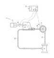
図1は、本発明の実施の形態に係るプライミングシステム1の主な構成を示す概略図である。
図1のプライミングシステム1は、例えば、手術中において、一時的に心臓と肺の機能を代行する人工肺等を備える体外循環装置を患者に装着する前に、体外循環装置の機器等に装着される構成となっている。
この体外循環装置は、患者と人工肺等をチューブ等の回路で接続し、この回路内に血液を循環させる。したがって、実際に患者の血液をチューブ等の回路に循環させる前に、この回路にプライミング液を充填するプライミング動作が実行される。
この回路には、図1に示すように、機器である例えば、チューブ2a、2b、2c、ドライブモータ9で駆動される遠心ポンプ3及び人工肺4等の人工心肺回路等が含まれる。FIG. 1 is a schematic view showing the main configuration of a
The
This extracorporeal circulation device connects a patient and an artificial lung with a circuit such as a tube, and circulates blood in this circuit. Therefore, prior to actually circulating the patient's blood into a circuit such as a tube, a priming operation is performed to fill the circuit with priming fluid.
This circuit includes, as shown in FIG. 1, devices such as
また、プライミングシステム1は、図1に示すように、プライミング液である例えば、生理食塩水から成るプライミング液を所定量、収容しているプライミング液収容部である例えば、プライミングバッグ5やプライミングバッグ5内のプライミング液をチューブ2a等に供給するために貯水するプライミング液貯水部である例えば、リザーバ6を有している。 Further, as shown in FIG. 1, the
このリザーバ6は、図1に示すように、プライミング液を遠心ポンプ3や人工肺4に向けて供給するためのチューブ2bと接続されていると共に、人工肺4を通過したプライミング液をリザーバ6へ戻すためのチューブ2aとも接続されている。
したがって、図1に示すように、リザーバ6から供給されたプライミング液は、チューブ2b、遠心ポンプ3、チューブ2c、人工肺4及びチューブ2aを介してリザーバ6へ循環する構成となっている。The
Therefore, as shown in FIG. 1, the priming solution supplied from the
また、リザーバ6は、人工肺4,遠心ポンプ3及びチューブ2a等から成る回路(人工心肺回路等)中に収容しきれないプライミング液を収容する機能も有する。
そして、リザーバ6は、リザーバ6内に収容されているプライミング液の量を計測する液面レベルセンサ7を有している。The
The
一方、プライミングバッグ5の開口部であるポートには、プライミングバッグ5内のプライミング液がリザーバ6に導入された量を計測すると共に気泡も検知可能な流量気泡センサ8が配置されている。
そして、これら流量気泡センサ8と液面レベルセンサ7は、プライミングシステム1を制御し管理するプライミング管理装置である例えば、コントローラ10と通信可能に接続されている。On the other hand, at a port which is an opening of the
The flow
図1のプライミングシステム1は、正確には、プライミングシステム1がプライミング動作を開始する前の状態を示す概略図となっている。 The
図1のコントローラ10には、図1に示すように、各種情報を入力すると共に表示する表示部である例えば、「タッチパネル13」が形成されている。
タッチパネル13は「位置入力装置付き表示装置」であって、液晶パネル等の表示装置とタッチパッド等の位置入力装置を組み合わせた電子部品である。したがって、画面上の表示を押すことで各種情報を入力することができると共に、各種情報を表示することができる構成となっている。
また、コントローラ10には、各種情報を入力する入力装置14(例えば、スイッチ等)も備えている。As shown in FIG. 1, the
The
The
図1に示すコントローラ10等は、コンピュータを有し、コンピュータは、図示しないCPU(Central Processing Unit)、RAM(Random Access Memory)、ROM(Read Only Memory)等を有し、これらは、バスを介して接続されている。 The
図2は、図1に示すコントローラ10の主な構成を示す概略ブロック図である。
図2に示すように、コントローラ10は、「制御部11」を有し、制御部11は、コントローラ10が「流量気泡センサ8」や「液面レベルセンサ7」等と通信するための「通信装置12」、タッチパネル13、入力装置14等を制御する。
また、制御部11は、図2に示す「第1の各種情報記憶部20」及び「第2の各種情報記憶部30」も制御する。FIG. 2 is a schematic block diagram showing a main configuration of
As shown in FIG. 2, the
The
図3及び図4は、それぞれ「第1の各種情報記憶部20」及び「第2の各種情報記憶部30」の主な構成を示す概略ブロック図である。これらの具体的な内容は後述する。 FIG.3 and FIG.4 is a schematic block diagram which shows the main structure of "1st various
図5乃至図7は、本実施の形態に係るプライミングシステム1の主な動作例等を示す概略フローチャートである。
本実施の形態では、上述の体外循環装置に使用する機器であるチューブ2a等、遠心ポンプ3及び人工肺4を手術前にプライミング等する例に基づいて以下、説明する。
先ず、図5のステップ(以下「ST」とする。)1では、図1のコントローラ10のタッチパネル13に、プライミング対象である図1に示す「チューブ2a、2b、2c」、「人工肺4」及び「遠心ポンプ3」の各パーツの容積データの入力を求める画面が表示される。5 to 7 are schematic flowcharts showing main operation examples and the like of the
In the present embodiment, the following description will be made based on an example in which the centrifugal pump 3 and the
First, in step 1 (hereinafter referred to as "ST") 1 of FIG. 5, the "
操作者が、例えば、チューブ2a等が「205ml」、人工肺4が「250ml」、「遠心ポンプ3が「45ml」と入力すると、ST2へ進む。
ST2では、入力された「チューブ(205ml)」、「人工肺(250ml)」、「遠心ポンプ(45ml)」の各パーツの容積データ(機器許容量情報の一例)を図3のコントローラ10の「部品容積データ記憶部21」に記憶する。
これにより、コントローラ10は、プライミング液でプライミングする機器である「チューブ2a等(205ml)」、「人工肺4(250ml)」、「遠心ポンプ3(45ml)」の容積データを取得することができる。When the operator inputs, for example, "205 ml" for the
In ST2, the volume data (an example of the equipment tolerance information) of each part of "tube (205 ml)", "artificial lung (250 ml)" and "centrifugal pump (45 ml)" input in ST2 of
Thereby, the
次いで、ST3で、コントローラ10のタッチパネル13に、プライミング液を注入する予定量である注入量(プライミング液総量情報の一例)の入力画面が表示される。 Next, in ST3, an input screen of an injection amount (an example of priming solution total amount information) which is a planned amount for injecting the priming solution is displayed on the
操作者が、例えば、プライミング液の注入量を「2000ml」と入力すると、ST4へ進む。
ST4では、入力された「プライミング液の注入量(2000ml)」を図3の「プライミング液注入量記憶部22」に記憶する。
これにより、コントローラ10は、プライミング対象である「チューブ2a等(205ml)」、「人工肺4(250ml)」、「遠心ポンプ3(45ml)」に注入するプライミング液の総注入量のデータを取得することができる。If the operator inputs, for example, the injection amount of priming solution as "2000 ml", the process proceeds to ST4.
At ST4, the input "priming solution injection amount (2000 ml)" is stored in the "priming solution injection
Thereby, the
次いで、ST5へ進む。ST5では、コントローラ10のタッチパネル13に、図1の液面レベルセンサ7をリザーバ6に装着すべき旨と装着されたか否かの入力画面が表示される。
操作者が液面レベルセンサ7をリザーバ6に装着し、装着した旨の入力を行うと、ST6で装着されたと判断され、ST7へ進む。Next, the process proceeds to ST5. In ST5, the
When the operator mounts the
ST7では、コントローラ10のタッチパネル13に、流量気泡センサ8をプライミングバッグ5につながれた「ポート」に装着すべき旨と装着されたか否かの入力画面が表示される。 In ST7, the
操作者が、流量気泡センサ8を、図1に示すようにプライミングバッグ5につながれた「ポート」に装着し、装着した旨の入力を行うと、ST8で、装着されたと判断され、ST9へ進む。
以上で、チューブ2a等の機器をプライミングするプライミングシステム1を動作させるための準備が完了したので、次に機器(チューブ2a等、人工肺4及び遠心ポンプ3で形成される回路)へのプライミング液の実際の注入(供給)が開始される。When the operator mounts the flow
With the above, preparation for operating the
先ず、ST9では、コントローラ10のタッチパネル13に、プライミングバッグ5の「開口部(ポート)」を開状態にすべき旨と開状態にしたか否かの入力画面が表示される。 First, in ST9, an input screen indicating whether the "opening (port)" of the priming
操作者がプライミングバッグ5の「開口部(ポート)」を開状態にし、開状態にした旨の入力を行うと、ST10で開状態と判断され、プライミングバッグ5内のプライミング液がリザーバ6へ導入された事実を確認する。また、リザーバ6へ導入されたプライミング液はチューブ2bへ供給される。 When the operator makes the "opening (port)" of priming
次いで、ST11へ進む。ST11では、図3の「通常プライミング操作処理部(プログラム)23」が動作し、遠心ポンプ3を動作させ、機器(回路)内のプライミングを行う「通常プライミング動作」が実行される。
図8は、プライミングバッグ5からプライミング液がリザーバ6に供給されながら遠心ポンプ3が動作し、プライミング動作を実行する状態を示す概略図である。
プライミング液は、遠心ポンプ3の動作により、チューブ2b、遠心ポンプ3、チューブ2c、人工肺4、チューブ2aを介して、リザーバ6に戻る循環を開始する。そして、これにより機器(回路)のプライミングが実行される。Next, the process proceeds to ST11. In ST11, the “normal priming operation processing unit (program) 23” in FIG. 3 operates, and the centrifugal pump 3 is operated to execute the “normal priming operation” for priming the device (circuit).
FIG. 8 is a schematic view showing a state in which the centrifugal pump 3 operates while the priming solution is supplied from the priming
The priming solution starts circulation back to the
次いで、ST12へ進む。ST12では、図3の「注水量制御処理部(プログラム)24」が動作し、流量気泡センサ8及びプライミング液注入量記憶部22を参照し、流量気泡センサ8の値が予定の注入量であるプライミング液注入量(例えば、2000ml)に達したか否かを判断する。 Next, the process proceeds to ST12. In ST12, the “water injection amount control processing unit (program) 24” in FIG. 3 operates, and the flow
ST13で、プライミング液注入量(例えば、2000ml)に達したと判断したときは、ST14へ進む。
ST14では、注水量制御処理部(プログラム)24が動作し、コントローラ10のタッチパネル13に、プライミングバッグ5の開口部を閉状態(注水停止)にすべき旨の表示と「注水停止」にしたか否かの入力画面が表示される。If it is determined at ST13 that the priming solution injection amount (for example, 2000 ml) has been reached, the process proceeds to ST14.
In ST14, the water injection amount control processing unit (program) 24 operates, and is displayed on the
操作者が、プライミングバッグ5の開口部を閉状態(注水停止)にし、「注水停止」にした旨の入力を行うと、ST15で、注水停止されたと判断される。
この段階で、プライミングバッグ5は、予定されたプライミング液の注入が終了する。When the operator enters the opening of the priming
At this stage, the priming
次いで、ST16へ進む。ST16では、コントローラ10のタッチパネル13に、流量気泡センサ8を血液回路(チューブ2a)に装着すべき旨の表示と装着したか否かの入力画面が表示される。
操作者が、プライミングバッグ5側に装着されていた流量気泡センサ8をチューブ2a側に装着し、装着した旨の入力を行うと、ST17で、流量気泡センサ8の装着があったと判断される。
図9は、流量気泡センサ8がチューブ2aに装着された状態を示す概略図である。Next, the process proceeds to ST16. In ST16, the
When the operator mounts the flow
FIG. 9 is a schematic view showing the flow
次いで、ST18に進む。ST18では、チューブ2aに装着された流量気泡センサ8が要排除現象である例えば、空気を検知したときは、コントローラ10がドライブモータ9を介して遠心ポンプ3に、チューブ2a等の回路内に滞留している空気の除去のための動作を実行させる。
すなわち、コントローラ10は、例えば、ドライブモータ9に間欠駆動等を実行させる。Next, the process proceeds to ST18. In ST18, when the flow
That is, the
以上で、回路内のプライミングが実行され、チューブ2a等内の気泡の除去が実行されるが、流量気泡センサ8では、検知できない人工肺4の内部に未だ空気が滞留しているおそれがある。
そこで、本実施の形態では、以下の工程が実行される。
先ず、ST19では、図3の「残留プライミング液データ生成処理部(プログラム)25」が動作し、図1の液面レベルセンサ7の計測値から、リザーバ6内のプライミング液残余情報である例えば、残留プライミング液の量を取得し、図3の「残留プライミング液データ記憶部26」に記憶する。
本実施の形態では、例えば、1600mlと記憶される。As described above, the priming in the circuit is performed, and the removal of the air bubbles in the
Therefore, in the present embodiment, the following steps are performed.
First, in ST19, the "remaining priming fluid data generation processing unit (program) 25" of FIG. 3 is operated, and based on the measurement value of the
In the present embodiment, for example, 1600 ml is stored.
次いで、ST20へ進む。ST20では、図4の「未充填量データ算出処理部(プログラム)31」が動作し、「部品容積データ記憶部21」、「残留プライミング液データ記憶部26」及び「プライミング液注入量記憶部22」を参照し、これらのデータを図4の「未充填量算出式記憶部32」の式に代入し演算する。 Next, the process proceeds to ST20. In ST20, “unfilled amount data calculation processing unit (program) 31” in FIG. 4 operates, and “component volume
この式は、例えば、(部品容積データ(チューブ2a等、人工肺4、遠心ポンプ3)+残留プライミング液データ)−プライミング液注入量=未充填量という内容となっている。
すなわち、プライミング対象の機器の全体の容積と残留プライミング液データを足した量は、プライミング液注入量と同じであるため、この量が同じでない場合は、何らかの気泡等が存在することが式により容易に判断可能な構成となっている。This equation is, for example, (part volume data (
That is, since the total volume of the device to be primed and the amount of residual priming fluid data are the same as the priming fluid injection amount, if this amount is not the same, it is easy for the equation to have some bubbles etc. It is a configuration that can be judged.
図10は、未充填量算出式の概略説明図である。図10に示すように、機器内に気泡が存在する場合は、その気泡の体積分だけ「未充填量」として明確になり、簡易な方法で流量気泡センサ8が検知できない気泡の存在を精度良く把握することができる。 FIG. 10 is a schematic explanatory view of the unfilled amount calculation formula. As shown in FIG. 10, when air bubbles are present in the device, only the volume of the air bubbles becomes clear as the "unfilled amount", and the presence of air bubbles which can not be detected by the flow rate
本実施の形態では、例えば、「(部品容積データとして「500ml」)+(残留プライミング液データとして「1600ml」)」−(プライミング液注入量として「2000ml」)=(未充填量データが「100ml」)なので、100mlを図4の「未充填量データ記憶部33」に記憶することとなる。 In the present embodiment, for example, “(500 ml as part volume data) + (1600 ml as residual priming fluid data)” − (2000 ml as priming fluid injection amount) = (100 ml as unfilled data) Therefore, 100 ml will be stored in the "unfilled amount
次いで、ST21へ進む。ST21では、図4の「未充填量有無判断処理部(プログラム)34」が動作し、「未充填量データ記憶部33」の未充填量データが「0」であるか否かを判断する。
ST22で「0」と判断されないときは、「未充填量」があり、気泡が存在すると判断し、ST23へ進む。Next, the process proceeds to ST21. In ST21, the "unfilled amount presence / absence determination processing unit (program) 34" of FIG. 4 operates to determine whether the unfilled amount data of the "unfilled amount
If it is not determined as "0" in ST22, it is determined that there is an "unfilled amount" and air bubbles are present, and the process proceeds to ST23.
ST23では、「未充填量有無判断処理部(プログラム)34」が動作し、遠心ポンプ3が動作し、気泡除去のための動作を一定時間実行する。
一方、ST22で「0」であるときは、「未充填量」がなく、気泡が存在しないと判断して、終了する。In ST23, the "unfilled amount presence / absence determination processing unit (program) 34" operates, the centrifugal pump 3 operates, and the operation for bubble removal is executed for a predetermined time.
On the other hand, when it is "0" in ST22, it is judged that there is no "unfilled amount" and there are no air bubbles, and the process is ended.
以上のように、本実施の形態では、プライミング動作中の滞留空気は、流量気泡センサ8等で検知されるのみならず、流量気泡センサ8では検知できない部分、例えば、人工肺4内に存在する場合でも、プライミング液の変化量に基づいて、簡易な方法で精度良く検知し、排除することができる。 As described above, in the present embodiment, the staying air during the priming operation is not only detected by the
なお、本実施の形態では、リザーバ6内のプライミング液の量を計測するために液面レベルセンサ7を使用したが、本発明は、これに限らず、リザーバ6に重量計を付けてリザーバ6内の液量を計測しても構わない。
また、液面レベルセンサ7の代わりに、リザーバ6下端の圧力値を計測して液量を計測しても構わない。Although the
Further, instead of the
また、本実施の形態では、ST22で、未充填量が「0」であるか否かで、滞留空気の有無を判断しているが、これに限らず、一定の幅の数値範囲内に含まれるか否かで判断しても構わない。 Further, in the present embodiment, the presence or absence of the staying air is determined in ST22 based on whether or not the unfilled amount is “0” in ST22. However, the present invention is not limited thereto. It does not matter if it is judged whether it is possible or not.
さらに、本実施の形態では、流量気泡センサ8をプライミングバッグ5側からチューブ2a側に付け替える構成となっているが、これに限らず、2つの流量気泡センサをそれぞれ、プライミングバッグ5側とチューブ2a側に配置しても構わない。 Furthermore, in the present embodiment, the flow amount
1・・・プライミングシステム、2a、2b、2c・・・チューブ、3・・・遠心ポンプ、4・・・人工肺、5・・・プライミングバッグ、6・・・リザーバ、7・・・液面レベルセンサ、8・・・流量気泡センサ、9・・・ドライブモータ、10・・・コントローラ、11・・・制御部、12・・・通信装置、13・・・タッチパネル、14・・・入力装置、20・・・第1の各種情報記憶部、21・・・部品容積データ記憶部、22・・・プライミング液注入量記憶部、23・・・通常プライミング操作処理部(プログラム)、24・・・注水量制御処理部(プログラム)、25・・・残留プライミング液データ生成処理部(プログラム)、26・・・残留プライミング液データ記憶部、30・・・第2の各種情報記憶部、31・・・未充填量データ算出処理部(プログラム)、32・・・未充填量算出式記憶部、33・・・未充填量データ記憶部、34・・・未充填量有無判断処理部(プログラム) DESCRIPTION OF
Claims (5)
Translated fromJapanese前記機器内に導入されるプライミング液と、
前記プライミング液を収容するプライミング液収容部と、
前記プライミング液を前記機器内に向けて供給するために前記プライミング液を、前記プライミング液収容部から導入すると共に、導入した前記プライミング液を貯水するプライミング液貯水部と、を有し、
前記プライミング液貯水部内の前記プライミング液の量は、前記機器内に導入された前記プライミング液の変化量によって変化する構成となっているプライミングシステムを管理するプライミング管理装置であって、
少なくとも、前記プライミング液収容部から導入した前記プライミング液の総量情報であるプライミング液総量情報、前記機器における前記プライミング液の収容可能な許容量情報である機器許容量情報及び前記機器の前記プライミング液を供給した後の前記プライミング液貯水部内における前記プライミング液の収容量情報であるプライミング液残余情報に基づいて、前記プライミング液内の要排除現象の有無を判断する構成となっていることを特徴とするプライミング管理装置。The device to be primed,
A priming solution introduced into the device;
A priming solution storage unit for storing the priming solution;
A priming solution storage unit for introducing the priming solution from the priming solution storage unit and supplying the priming solution into the device, and storing the introduced priming solution;
The priming management apparatus manages a priming system in which an amount of the priming solution in the priming solution reservoir is changed according to a change amount of the priming solution introduced into the device.
The priming fluid total amount information which is the total amount information of the priming fluid introduced from the priming fluid storage unit, the device tolerance information which is the capacity information of the priming fluid in the device, and the priming fluid of the device It is characterized in that the presence or absence of the exclusion phenomenon in the priming solution is judged based on the priming solution residual information which is the capacity information of the priming solution in the priming solution storage section after the supply. Priming management device.
前記機器内に導入されるプライミング液と、
前記プライミング液を収容するプライミング液収容部と、
前記プライミング液を前記機器内に向けて供給するために前記プライミング液を、前記プライミング液収容部から導入すると共に、導入した前記プライミング液を貯水するプライミング液貯水部と、を有し、
前記プライミング液貯水部内の前記プライミング液の量は、前記機器内に導入された前記プライミング液の変化量によって変化する構成となっており、
少なくとも、前記プライミング液収容部から導入した前記プライミング液の総量情報であるプライミング液総量情報、前記機器における前記プライミング液の収容可能な許容量情報である機器許容量情報及び前記機器の前記プライミング液を供給した後の前記プライミング液貯水部内における前記プライミング液の収容量情報であるプライミング液残余情報に基づいて、前記プライミング液内の要排除現象の有無を判断するプライミング管理装置を有することを特徴とするプライミングシステム。The device to be primed,
A priming solution introduced into the device;
A priming solution storage unit for storing the priming solution;
A priming solution storage unit for introducing the priming solution from the priming solution storage unit and supplying the priming solution into the device, and storing the introduced priming solution;
The amount of the priming solution in the priming solution reservoir is configured to change according to the amount of change of the priming solution introduced into the device,
The priming fluid total amount information which is the total amount information of the priming fluid introduced from the priming fluid storage unit, the device tolerance information which is the capacity information of the priming fluid in the device, and the priming fluid of the device The apparatus further comprises a priming management device that determines the presence or absence of an exclusion phenomenon in the priming solution based on priming solution residual information which is information on the capacity of the priming solution in the priming solution storage section after the supply. Priming system.
少なくとも、前記プライミング液収容部から導入した前記プライミング液の総量情報であるプライミング液総量情報、前記機器における前記プライミング液の収容可能な許容量情報である機器許容量情報及び前記機器の前記プライミング液を供給した後の前記プライミング液貯水部内における前記プライミング液の収容量情報であるプライミング液残余情報に基づいて、前記プライミング液内の要排除現象の有無を判断する構成となっていることを特徴とするプライミング管理装置の制御方法。A device to be primed, a priming solution introduced into the device, a priming solution storage unit for storing the priming solution, the priming solution for supplying the priming solution into the device, the priming solution And a priming solution storage section for storing the introduced priming solution while being introduced from the solution storage section, wherein the volume of the priming solution in the priming solution storage section is the volume of the priming solution introduced into the device. A control method of a priming device having a configuration that changes according to a change amount,
The priming fluid total amount information which is the total amount information of the priming fluid introduced from the priming fluid storage unit, the device tolerance information which is the capacity information of the priming fluid in the device, and the priming fluid of the device It is characterized in that the presence or absence of the exclusion phenomenon in the priming solution is judged based on the priming solution residual information which is the capacity information of the priming solution in the priming solution storage section after the supply. Control method of priming management device.
Priority Applications (1)
| Application Number | Priority Date | Filing Date | Title |
|---|---|---|---|
| JP2015177693AJP6522470B2 (en) | 2015-09-09 | 2015-09-09 | Priming management device, priming system, control method for priming management device, and control program for priming management device |
Applications Claiming Priority (1)
| Application Number | Priority Date | Filing Date | Title |
|---|---|---|---|
| JP2015177693AJP6522470B2 (en) | 2015-09-09 | 2015-09-09 | Priming management device, priming system, control method for priming management device, and control program for priming management device |
Publications (2)
| Publication Number | Publication Date |
|---|---|
| JP2017051423A JP2017051423A (en) | 2017-03-16 |
| JP6522470B2true JP6522470B2 (en) | 2019-05-29 |
Family
ID=58316073
Family Applications (1)
| Application Number | Title | Priority Date | Filing Date |
|---|---|---|---|
| JP2015177693AActiveJP6522470B2 (en) | 2015-09-09 | 2015-09-09 | Priming management device, priming system, control method for priming management device, and control program for priming management device |
Country Status (1)
| Country | Link |
|---|---|
| JP (1) | JP6522470B2 (en) |
Families Citing this family (1)
| Publication number | Priority date | Publication date | Assignee | Title |
|---|---|---|---|---|
| US11413386B2 (en)* | 2019-08-09 | 2022-08-16 | Fresenius Medical Care Holdings, Inc. | Volume-based priming of dialysis machines |
Family Cites Families (4)
| Publication number | Priority date | Publication date | Assignee | Title |
|---|---|---|---|---|
| JP5595930B2 (en)* | 2008-01-23 | 2014-09-24 | デカ・プロダクツ・リミテッド・パートナーシップ | Disposable components for fluid line automatic connection systems |
| JP2011136003A (en)* | 2009-12-28 | 2011-07-14 | Nikkiso Co Ltd | Blood purifying device and priming method thereof |
| DE102011018601B4 (en)* | 2011-04-21 | 2017-04-06 | Fresenius Medical Care Deutschland Gmbh | Apparatus for extracorporeal blood treatment and method for monitoring the fluid flow of an extracorporeal blood treatment device |
| JP5851616B2 (en)* | 2012-08-30 | 2016-02-03 | テルモ株式会社 | Control device, circulation device and control method |
- 2015
- 2015-09-09JPJP2015177693Apatent/JP6522470B2/enactiveActive
Also Published As
| Publication number | Publication date |
|---|---|
| JP2017051423A (en) | 2017-03-16 |
Similar Documents
| Publication | Publication Date | Title |
|---|---|---|
| TWI333852B (en) | Method of testing a surgical system | |
| US9814833B2 (en) | Pressure based refill status monitor for implantable pumps | |
| US7160259B2 (en) | Fluid manipulating system for therapy apparatus | |
| CN111107893B (en) | Systems and methods for intravascular fluid injection simulation | |
| BR112016006753B1 (en) | SENSOR SYSTEM FOR PHASE DETECTION AND / OR PHASE TRANSITIONS IN PERITONEAL DIALYSIS TREATMENTS | |
| JP6998444B2 (en) | Blood coagulation test system and control method of blood coagulation test system | |
| KR20130045277A (en) | Hemodialysis system | |
| AU2021248489A1 (en) | System for air volume correction based on fluid pressure and flow rate | |
| JP6522470B2 (en) | Priming management device, priming system, control method for priming management device, and control program for priming management device | |
| US10220130B2 (en) | Device and method for balancing between an inflow into and an outflow out of a medical treatment device | |
| JP5190456B2 (en) | Method for filling a metering device of a therapeutic instrument and therapeutic instrument | |
| CN109357738A (en) | The weighing method of peritoneal dialysis electronic scale | |
| CN109789280B (en) | Method and apparatus for intraoperative determination of drag coefficients of different medical instruments using a medical fluid pump | |
| US12263321B2 (en) | Method for ascertaining the vertical distance between a patient (level of surgical intervention) and a fluid delivery pump | |
| CN106659835B (en) | Method and apparatus for removing blood from an extracorporeal blood circuit under pressure control | |
| EP3785747A1 (en) | Systems and methods for providing zones of selective thermal therapy | |
| JPWO2019044767A1 (en) | Edema information management device, extracorporeal circulation management device having the same, edema information management device control method, and edema information management device control program | |
| US11654223B2 (en) | Extracorporeal circulation management device with blood level detection in a reservoir without a sensor | |
| JP2006043463A (en) | Fluid mixer and method according to a determined ratio of biological fluid to solution | |
| JP6266945B2 (en) | Medical liquid flow rate calculation device and medical liquid pump | |
| CN108051141A (en) | Pressure-adjustable ultrasonic imitation body | |
| JP2024178457A (en) | Injection system, control method, and control program | |
| JPH0420349A (en) | Thrombus dissolving medical treatment device | |
| CN102692330A (en) | Power test model of left ventricular assist device | |
| CN119524260A (en) | Cascade control method and infusion device for physiological saline and contrast agent |
Legal Events
| Date | Code | Title | Description |
|---|---|---|---|
| A621 | Written request for application examination | Free format text:JAPANESE INTERMEDIATE CODE: A621 Effective date:20180606 | |
| RD04 | Notification of resignation of power of attorney | Free format text:JAPANESE INTERMEDIATE CODE: A7424 Effective date:20181220 | |
| TRDD | Decision of grant or rejection written | ||
| A01 | Written decision to grant a patent or to grant a registration (utility model) | Free format text:JAPANESE INTERMEDIATE CODE: A01 Effective date:20190403 | |
| A977 | Report on retrieval | Free format text:JAPANESE INTERMEDIATE CODE: A971007 Effective date:20190329 | |
| A61 | First payment of annual fees (during grant procedure) | Free format text:JAPANESE INTERMEDIATE CODE: A61 Effective date:20190424 | |
| R150 | Certificate of patent or registration of utility model | Ref document number:6522470 Country of ref document:JP Free format text:JAPANESE INTERMEDIATE CODE: R150 | |
| R250 | Receipt of annual fees | Free format text:JAPANESE INTERMEDIATE CODE: R250 | |
| R250 | Receipt of annual fees | Free format text:JAPANESE INTERMEDIATE CODE: R250 | |
| R250 | Receipt of annual fees | Free format text:JAPANESE INTERMEDIATE CODE: R250 | |
| R250 | Receipt of annual fees | Free format text:JAPANESE INTERMEDIATE CODE: R250 |