JP6522071B2 - Decoupling of instrument shaft roll and end effector actuation in a surgical instrument - Google Patents
Decoupling of instrument shaft roll and end effector actuation in a surgical instrumentDownload PDFInfo
- Publication number
- JP6522071B2 JP6522071B2JP2017181392AJP2017181392AJP6522071B2JP 6522071 B2JP6522071 B2JP 6522071B2JP 2017181392 AJP2017181392 AJP 2017181392AJP 2017181392 AJP2017181392 AJP 2017181392AJP 6522071 B2JP6522071 B2JP 6522071B2
- Authority
- JP
- Japan
- Prior art keywords
- torque
- main shaft
- end effector
- rotation
- link
- Prior art date
- Legal status (The legal status is an assumption and is not a legal conclusion. Google has not performed a legal analysis and makes no representation as to the accuracy of the status listed.)
- Active
Links
Images


Classifications
- A—HUMAN NECESSITIES
- A61—MEDICAL OR VETERINARY SCIENCE; HYGIENE
- A61B—DIAGNOSIS; SURGERY; IDENTIFICATION
- A61B34/00—Computer-aided surgery; Manipulators or robots specially adapted for use in surgery
- A61B34/70—Manipulators specially adapted for use in surgery
- A—HUMAN NECESSITIES
- A61—MEDICAL OR VETERINARY SCIENCE; HYGIENE
- A61B—DIAGNOSIS; SURGERY; IDENTIFICATION
- A61B17/00—Surgical instruments, devices or methods
- A—HUMAN NECESSITIES
- A61—MEDICAL OR VETERINARY SCIENCE; HYGIENE
- A61B—DIAGNOSIS; SURGERY; IDENTIFICATION
- A61B17/00—Surgical instruments, devices or methods
- A61B17/00234—Surgical instruments, devices or methods for minimally invasive surgery
- A—HUMAN NECESSITIES
- A61—MEDICAL OR VETERINARY SCIENCE; HYGIENE
- A61B—DIAGNOSIS; SURGERY; IDENTIFICATION
- A61B17/00—Surgical instruments, devices or methods
- A61B17/28—Surgical forceps
- A61B17/29—Forceps for use in minimally invasive surgery
- A—HUMAN NECESSITIES
- A61—MEDICAL OR VETERINARY SCIENCE; HYGIENE
- A61B—DIAGNOSIS; SURGERY; IDENTIFICATION
- A61B34/00—Computer-aided surgery; Manipulators or robots specially adapted for use in surgery
- A61B34/30—Surgical robots
- A—HUMAN NECESSITIES
- A61—MEDICAL OR VETERINARY SCIENCE; HYGIENE
- A61B—DIAGNOSIS; SURGERY; IDENTIFICATION
- A61B34/00—Computer-aided surgery; Manipulators or robots specially adapted for use in surgery
- A61B34/70—Manipulators specially adapted for use in surgery
- A61B34/71—Manipulators operated by drive cable mechanisms
- A—HUMAN NECESSITIES
- A61—MEDICAL OR VETERINARY SCIENCE; HYGIENE
- A61B—DIAGNOSIS; SURGERY; IDENTIFICATION
- A61B90/00—Instruments, implements or accessories specially adapted for surgery or diagnosis and not covered by any of the groups A61B1/00 - A61B50/00, e.g. for luxation treatment or for protecting wound edges
- A61B90/03—Automatic limiting or abutting means, e.g. for safety
- A—HUMAN NECESSITIES
- A61—MEDICAL OR VETERINARY SCIENCE; HYGIENE
- A61B—DIAGNOSIS; SURGERY; IDENTIFICATION
- A61B17/00—Surgical instruments, devices or methods
- A61B17/28—Surgical forceps
- A—HUMAN NECESSITIES
- A61—MEDICAL OR VETERINARY SCIENCE; HYGIENE
- A61B—DIAGNOSIS; SURGERY; IDENTIFICATION
- A61B17/00—Surgical instruments, devices or methods
- A61B2017/00017—Electrical control of surgical instruments
- A—HUMAN NECESSITIES
- A61—MEDICAL OR VETERINARY SCIENCE; HYGIENE
- A61B—DIAGNOSIS; SURGERY; IDENTIFICATION
- A61B17/00—Surgical instruments, devices or methods
- A61B2017/00367—Details of actuation of instruments, e.g. relations between pushing buttons, or the like, and activation of the tool, working tip, or the like
- A61B2017/00398—Details of actuation of instruments, e.g. relations between pushing buttons, or the like, and activation of the tool, working tip, or the like using powered actuators, e.g. stepper motors, solenoids
- A—HUMAN NECESSITIES
- A61—MEDICAL OR VETERINARY SCIENCE; HYGIENE
- A61B—DIAGNOSIS; SURGERY; IDENTIFICATION
- A61B17/00—Surgical instruments, devices or methods
- A61B2017/00477—Coupling
- A—HUMAN NECESSITIES
- A61—MEDICAL OR VETERINARY SCIENCE; HYGIENE
- A61B—DIAGNOSIS; SURGERY; IDENTIFICATION
- A61B17/00—Surgical instruments, devices or methods
- A61B17/28—Surgical forceps
- A61B17/29—Forceps for use in minimally invasive surgery
- A61B2017/2901—Details of shaft
- A—HUMAN NECESSITIES
- A61—MEDICAL OR VETERINARY SCIENCE; HYGIENE
- A61B—DIAGNOSIS; SURGERY; IDENTIFICATION
- A61B17/00—Surgical instruments, devices or methods
- A61B17/28—Surgical forceps
- A61B17/29—Forceps for use in minimally invasive surgery
- A61B2017/2901—Details of shaft
- A61B2017/2902—Details of shaft characterized by features of the actuating rod
- A61B2017/2903—Details of shaft characterized by features of the actuating rod transferring rotary motion
- A—HUMAN NECESSITIES
- A61—MEDICAL OR VETERINARY SCIENCE; HYGIENE
- A61B—DIAGNOSIS; SURGERY; IDENTIFICATION
- A61B17/00—Surgical instruments, devices or methods
- A61B17/28—Surgical forceps
- A61B17/29—Forceps for use in minimally invasive surgery
- A61B2017/2926—Details of heads or jaws
- A61B2017/2927—Details of heads or jaws the angular position of the head being adjustable with respect to the shaft
- A61B2017/2929—Details of heads or jaws the angular position of the head being adjustable with respect to the shaft with a head rotatable about the longitudinal axis of the shaft
- A61B2017/293—Details of heads or jaws the angular position of the head being adjustable with respect to the shaft with a head rotatable about the longitudinal axis of the shaft with means preventing relative rotation between the shaft and the actuating rod
- A—HUMAN NECESSITIES
- A61—MEDICAL OR VETERINARY SCIENCE; HYGIENE
- A61B—DIAGNOSIS; SURGERY; IDENTIFICATION
- A61B17/00—Surgical instruments, devices or methods
- A61B17/28—Surgical forceps
- A61B17/29—Forceps for use in minimally invasive surgery
- A61B2017/2926—Details of heads or jaws
- A61B2017/2932—Transmission of forces to jaw members
- A61B2017/2933—Transmission of forces to jaw members camming or guiding means
- A61B2017/2936—Pins in guiding slots
- A—HUMAN NECESSITIES
- A61—MEDICAL OR VETERINARY SCIENCE; HYGIENE
- A61B—DIAGNOSIS; SURGERY; IDENTIFICATION
- A61B17/00—Surgical instruments, devices or methods
- A61B17/28—Surgical forceps
- A61B17/29—Forceps for use in minimally invasive surgery
- A61B2017/2926—Details of heads or jaws
- A61B2017/2932—Transmission of forces to jaw members
- A61B2017/2938—Independently actuatable jaw members, e.g. two actuating rods
- A—HUMAN NECESSITIES
- A61—MEDICAL OR VETERINARY SCIENCE; HYGIENE
- A61B—DIAGNOSIS; SURGERY; IDENTIFICATION
- A61B17/00—Surgical instruments, devices or methods
- A61B17/28—Surgical forceps
- A61B17/29—Forceps for use in minimally invasive surgery
- A61B2017/2926—Details of heads or jaws
- A61B2017/2932—Transmission of forces to jaw members
- A61B2017/2943—Toothed members, e.g. rack and pinion
- A—HUMAN NECESSITIES
- A61—MEDICAL OR VETERINARY SCIENCE; HYGIENE
- A61B—DIAGNOSIS; SURGERY; IDENTIFICATION
- A61B34/00—Computer-aided surgery; Manipulators or robots specially adapted for use in surgery
- A61B34/20—Surgical navigation systems; Devices for tracking or guiding surgical instruments, e.g. for frameless stereotaxis
- A61B2034/2046—Tracking techniques
- A61B2034/2059—Mechanical position encoders
- A—HUMAN NECESSITIES
- A61—MEDICAL OR VETERINARY SCIENCE; HYGIENE
- A61B—DIAGNOSIS; SURGERY; IDENTIFICATION
- A61B34/00—Computer-aided surgery; Manipulators or robots specially adapted for use in surgery
- A61B34/30—Surgical robots
- A61B2034/301—Surgical robots for introducing or steering flexible instruments inserted into the body, e.g. catheters or endoscopes
- A—HUMAN NECESSITIES
- A61—MEDICAL OR VETERINARY SCIENCE; HYGIENE
- A61B—DIAGNOSIS; SURGERY; IDENTIFICATION
- A61B34/00—Computer-aided surgery; Manipulators or robots specially adapted for use in surgery
- A61B34/30—Surgical robots
- A61B2034/302—Surgical robots specifically adapted for manipulations within body cavities, e.g. within abdominal or thoracic cavities
- A—HUMAN NECESSITIES
- A61—MEDICAL OR VETERINARY SCIENCE; HYGIENE
- A61B—DIAGNOSIS; SURGERY; IDENTIFICATION
- A61B34/00—Computer-aided surgery; Manipulators or robots specially adapted for use in surgery
- A61B34/30—Surgical robots
- A61B2034/303—Surgical robots specifically adapted for manipulations within body lumens, e.g. within lumen of gut, spine, or blood vessels
- A—HUMAN NECESSITIES
- A61—MEDICAL OR VETERINARY SCIENCE; HYGIENE
- A61B—DIAGNOSIS; SURGERY; IDENTIFICATION
- A61B34/00—Computer-aided surgery; Manipulators or robots specially adapted for use in surgery
- A61B34/70—Manipulators specially adapted for use in surgery
- A61B34/71—Manipulators operated by drive cable mechanisms
- A61B2034/715—Cable tensioning mechanisms for removing slack
- A—HUMAN NECESSITIES
- A61—MEDICAL OR VETERINARY SCIENCE; HYGIENE
- A61B—DIAGNOSIS; SURGERY; IDENTIFICATION
- A61B90/00—Instruments, implements or accessories specially adapted for surgery or diagnosis and not covered by any of the groups A61B1/00 - A61B50/00, e.g. for luxation treatment or for protecting wound edges
- A61B90/03—Automatic limiting or abutting means, e.g. for safety
- A61B2090/031—Automatic limiting or abutting means, e.g. for safety torque limiting
- A—HUMAN NECESSITIES
- A61—MEDICAL OR VETERINARY SCIENCE; HYGIENE
- A61B—DIAGNOSIS; SURGERY; IDENTIFICATION
- A61B90/00—Instruments, implements or accessories specially adapted for surgery or diagnosis and not covered by any of the groups A61B1/00 - A61B50/00, e.g. for luxation treatment or for protecting wound edges
- A61B90/06—Measuring instruments not otherwise provided for
- A61B2090/067—Measuring instruments not otherwise provided for for measuring angles
- A—HUMAN NECESSITIES
- A61—MEDICAL OR VETERINARY SCIENCE; HYGIENE
- A61B—DIAGNOSIS; SURGERY; IDENTIFICATION
- A61B34/00—Computer-aided surgery; Manipulators or robots specially adapted for use in surgery
- A61B34/30—Surgical robots
- A61B34/32—Surgical robots operating autonomously
- A—HUMAN NECESSITIES
- A61—MEDICAL OR VETERINARY SCIENCE; HYGIENE
- A61B—DIAGNOSIS; SURGERY; IDENTIFICATION
- A61B34/00—Computer-aided surgery; Manipulators or robots specially adapted for use in surgery
- A61B34/30—Surgical robots
- A61B34/37—Leader-follower robots
Landscapes
- Health & Medical Sciences (AREA)
- Life Sciences & Earth Sciences (AREA)
- Surgery (AREA)
- Engineering & Computer Science (AREA)
- Animal Behavior & Ethology (AREA)
- Veterinary Medicine (AREA)
- Biomedical Technology (AREA)
- Heart & Thoracic Surgery (AREA)
- Medical Informatics (AREA)
- Molecular Biology (AREA)
- Nuclear Medicine, Radiotherapy & Molecular Imaging (AREA)
- General Health & Medical Sciences (AREA)
- Public Health (AREA)
- Robotics (AREA)
- Ophthalmology & Optometry (AREA)
- Oral & Maxillofacial Surgery (AREA)
- Pathology (AREA)
- Manipulator (AREA)
- Surgical Instruments (AREA)
- Endoscopes (AREA)
- Transmission Devices (AREA)
Description
Translated fromJapanese(関連出願の相互参照)
本出願は、2010年11月15日に“METHOD FOR PASSIVELY DECOUPLING TORQUE APPLIED BY A REMOTE ACTUATOR INTO AN INDEPENDENTLY ROTATING MEMBER”の名称で出願された米国仮特許出願第61/413,885号(代理人整理番号ISRG 02930PROV/US)、及び2011年5月31日に“DECOUPLING INSTRUMENT SHAFT ROLL AND END EFFECTOR ACTUATION IN A SURGICAL INSTRUMENT”の名称で出願された米国仮特許出願第61/491,789号(代理人整理番号ISRG 03310/US)の利益を主張し、参照によりその全体が本明細書に援用される。(Cross-reference to related applications)
This application is based on US Provisional Patent Application No. 61 / 413,885, filed Nov. 15, 2010, entitled “METHOD FOR PASSIVELY DECOUPLING TORQUE APPLIED BY A REMOTE ACTUATOR INTO AN INDEPENDENTLY ROTATING MEMBER”. And US Provisional Patent Application No. 61 / 491,789, filed May 31, 2011, entitled "DECOUPLING INSTRUMENT SHAFT ROLL AND END EFFECTOR ACTUATION IN A SURGICAL INSTRUMENT". Claims the benefit of ISRG 03310 / US), which is hereby incorporated by reference in its entirety. It is use.
低侵襲手術技法は、診断又は外科手術中に傷つけられる無関係な組織の量を低減し、それによって患者の回復時間、不快感、及び有害な副作用を低減することを目的とする。結果として、標準的な手術の入院の平均的長さは、低侵襲手術技法を使用して、著しく短縮され得る。また、患者の回復時間、患者の不快感、手術の副作用、及び仕事を離れる時間も低侵襲性手術によって低減され得る。 Minimally invasive surgical techniques are aimed at reducing the amount of extraneous tissue that is damaged during diagnosis or surgery, thereby reducing patient recovery time, discomfort, and adverse side effects. As a result, the average length of a standard surgical hospital stay can be significantly shortened using minimally invasive surgical techniques. Also, patient recovery time, patient discomfort, side effects of surgery, and time to leave work can be reduced by minimally invasive surgery.
低侵襲性手術の一般的な形態は内視鏡検査であり、内視鏡検査の一般的な形態は、腹腔の内側の低侵襲性検査及び手術である、腹腔鏡検査である。標準的な腹腔鏡手術では、患者の腹部はガスを吹き込まれ、腹腔鏡器具用の進入ポートを提供するように、カニューレスリーブが小(約1/2インチ以下)切開部を通過させられる。 A common form of minimally invasive surgery is endoscopy and a common form of endoscopy is laparoscopy, which is a minimally invasive examination and surgery on the inside of the abdominal cavity. In standard laparoscopic surgery, the patient's abdomen is insufflated and a cannulated sleeve is passed through a small (about 1/2 inch or less) incision to provide an entry port for the laparoscopic instrument.
腹腔鏡手術器具は一般的に、手術野を視認するための内視鏡(腹腔鏡)、及び手術部位で作業するためのツールを含む。作業ツールは、各ツールの作業端又はエンドエフェクタが、延長チューブ(例えば、器具シャフト又はメインシャフトとしても知られる)によってそのハンドルから分離されることを除いて、従来の(観血)手術で使用されるものと一般的には同様である。エンドエフェクタは、例えば、クランプ、把持装置、鋏、吻合器、焼灼ツール、線形カッター、又は針ホルダを含むことができる。 Laparoscopic surgical instruments generally include an endoscope (laparoscope) for viewing the surgical field, and a tool for working at the surgical site. The working tools are used in conventional (open surgery) surgery except that the working end or end effector of each tool is separated from its handle by an extension tube (e.g. also known as an instrument shaft or main shaft) It is generally the same as The end effector can include, for example, a clamp, a grasper, a scissors, an anastomosis, a cautery tool, a linear cutter, or a needle holder.
外科手術を行うために、外科医は、作業ツールを、カニューレスリーブを通って内部手術部位まで通過させ、腹部の外側からそれらを操作する。外科医は、内視鏡から得られる手術部位の画像を表示するモニタから手術を視認する。同様の内視鏡技法が、例えば、関節鏡検査、後腹膜鏡検査、骨盤鏡検査、腎盂鏡検査、膀胱鏡検査、脳槽鏡検査、洞房鏡検査、子宮鏡検査、尿道鏡検査、及び同等のもので用いられる。 To perform a surgical procedure, the surgeon passes working tools through the cannula sleeve to the internal surgical site and manipulates them from outside the abdomen. The surgeon views the surgery from a monitor that displays an image of the surgical site obtained from the endoscope. Similar endoscopic techniques include, for example, arthroscopy, retroperitonoscopy, pelvicoscopy, nephroscopy, cystoscopy, alveolaroscopy, sinoasoscopy, hysteroscopy, hysteroscopy, urethroscopy, and the like Used in
低侵襲遠隔手術ロボットシステムは、内部手術部位で作業する時に外科医の器用さを増大させるように、及び外科医が遠隔地(滅菌野の外側)から患者に手術をすることを可能にするように、開発されている。遠隔手術システムでは、外科医はしばしば、制御コンソールにおいて手術部位の画像が提供される。適切なビューア又はディスプレイ上で手術部位の3次元画像を視認しながら、外科医は、制御コンソールのマスタ入力部又は制御デバイスを操作することによって、患者に外科手術を行う。マスタ入力デバイスのそれぞれは、サーボ機械的に作動/関節動作する手術器具の動きを制御する。外科手術中に、遠隔手術システムは、マスタ入力デバイスの操作に応じて、外科医のために様々な機能、例えば、針を保持又は押し込むこと、血管を把持すること、組織を解離すること、又は同様のこと等を果たす、エンドエフェクタを有する様々な手術器具又はツールの機械的作動及び制御を提供することができる。 A minimally invasive telesurgical robot system, to increase the dexterity of the surgeon when working at the internal surgical site, and to allow the surgeon to operate the patient from a remote location (outside the sterile field), It is being developed. In telesurgery systems, surgeons are often provided with images of the surgical site at the control console. While viewing a three-dimensional image of the surgical site on a suitable viewer or display, the surgeon performs surgery on the patient by manipulating the master input or control device of the control console. Each of the master input devices controls movement of servomechanically actuated / articulated surgical instruments. During surgery, the telesurgical system responds to the operation of the master input device to perform various functions, such as holding or pushing a needle, grasping a blood vessel, dissociating tissue, or the like for the surgeon Provide mechanical actuation and control of various surgical instruments or tools having end effectors.
多くの既存の低侵襲遠隔手術ロボットシステムでは、手術器具の操作は、幾つかのロボットアームを有する手術ロボットによって提供される。ロボットアームのそれぞれは、幾つかのロボットジョイント及び手術器具の取り付けのための装着具を有する。装着具の少なくとも1つに一体化されるのは、手術器具の対応する入力カプラに動力を伝えるように連結する幾つかの駆動カプラ(例えば、回転駆動カプラ)である。手術器具は、入力カプラを手術器具の対応する動き(例えば、メインシャフトの回転、エンドエフェクタのピッチ、エンドエフェクタのヨー、エンドエフェクタのあごのクランピング、ステープルの配置、組織の切断等)に動力を伝えるように結合する機構を含む。多くの既存の低侵襲遠隔手術ロボットシステムでは、それぞれの手術ロボットの駆動カプラは、例えば、ケーブル駆動作動システムにおいて可能であるように出力カプラの動きに対する正確な制御を提供するために、ケーブル駆動である。出力カプラの動きを正確に制御することによって、手術器具の対応する関連する動きに対する正確な制御が達成され得る。 In many existing minimally invasive telesurgical robot systems, manipulation of surgical instruments is provided by a surgical robot having several robotic arms. Each of the robotic arms has a number of robotic joints and mountings for attachment of surgical instruments. Integrated in at least one of the mountings is a number of drive couplers (e.g., rotational drive couplers) that couple power transfer to corresponding input couplers of the surgical instrument. The surgical tool powers the input coupler to the corresponding motion of the surgical tool (eg, rotation of the main shaft, pitch of the end effector, yaw of the end effector, clamping of the end effector jaws, placement of staples, cutting of tissue, etc.) Including mechanisms to combine to convey. In many existing minimally invasive telesurgical robot systems, the drive couplers of each surgical robot are cable driven, for example, to provide accurate control over the movement of the output coupler as possible in cable driven actuation systems. is there. By precisely controlling the movement of the output coupler, precise control over the corresponding associated movement of the surgical instrument can be achieved.
ケーブル駆動出力カプラは典型的には限られた可動域を有する。このような限られた可動域は、出力カプラがエンドエフェクタのその他の動きによって影響を及ぼされないエンドエフェクタの動きと関連する場合には、有害でない場合がある。しかし、このような限られた可動域は、出力カプラがエンドエフェクタのもう1つの動きによって影響を及ぼされるエンドエフェクタの動きと関連する場合には、有害になる場合がある。例えば、器具シャフトの回転は、エンドエフェクタ機構(例えば、クランピング機構、ステープルの配置のための機構、組織切断機構等)を駆動するために使用される駆動シャフトの回転に有害に結び付き得る。器具シャフトの回転及び駆動シャフトの回転に関連する出力カプラの補償動作が行われ得るが、このような補償動作は、主要目的のために使用され得る出力カプラの限られた可動域の一部を減少させる。 Cable drive output couplers typically have a limited range of motion. Such limited range of motion may not be harmful if the output coupler is associated with movement of the end effector not affected by other movements of the end effector. However, such limited range of motion may be detrimental if the output coupler is associated with the movement of the end effector affected by another movement of the end effector. For example, rotation of the instrument shaft can be detrimentally linked to rotation of a drive shaft used to drive an end effector mechanism (eg, a clamping mechanism, a mechanism for placement of staples, a tissue cutting mechanism, etc.). Although compensation operations of the output coupler related to the rotation of the instrument shaft and the rotation of the drive shaft may be performed, such compensation operations represent a portion of the limited range of motion of the output coupler that may be used for main purposes. Reduce.
したがって、手術器具の関連する動きを切り離す、特に手術器具の器具シャフトのロール及びエンドエフェクタの作動を切り離すための手術器具及び関連する方法に対する必要性があると考えられている。 Thus, it is believed that there is a need for a surgical instrument and associated method for decoupling the associated movement of the surgical instrument, in particular the actuation of the instrument shaft roll and the end effector of the surgical instrument.
これらのエンドエフェクタの操作及び制御はまた、ロボット手術システムの特に有益な態様である。この理由により、外科医の手首の自然な動作を模倣するように、エンドエフェクタの3自由度の回転動作を提供する機構を含む、手術ツールを提供することが望ましい。このような機構は、低侵襲手術に使用するために適切に寸法決定されるべきであるとともに、故障の可能性のあるポイントを低減するように比較的簡素な設計であるべきである。加えて、この様な機構は、エンドエフェクタが多種多様な位置で操作されることを可能にする、十分な運動範囲を提供するべきである。 The operation and control of these end effectors is also a particularly useful aspect of robotic surgery systems. For this reason, it is desirable to provide a surgical tool that includes a mechanism that provides three degrees of freedom of end effector rotational motion to mimic the natural motion of the surgeon's wrist. Such a mechanism should be properly sized for use in minimally invasive surgery and should be of relatively simple design to reduce potential points of failure. In addition, such a mechanism should provide a sufficient range of motion that allows the end effector to be manipulated in a wide variety of positions.
非ロボット式線形クランピング、切断、及びステープリングデバイスは、多くの異なる手術に採用されている。例えば、この様なデバイスは、胃腸管から癌性又は異常組織を切除するために使用されることができる。既知の線形クランピング、切断、及びステープリングデバイスを含む、多くの既知の手術デバイスはしばしば、患者の組織を操作するために使用される対向するあご部を有する。 Non-robotic linear clamping, cutting and stapling devices are employed in many different procedures. For example, such devices can be used to ablate cancerous or abnormal tissue from the gastrointestinal tract. Many known surgical devices, including known linear clamping, cutting and stapling devices, often have opposing jaws used to manipulate the patient's tissue.
対向するあご部を有する既知の装置に関して、著しい量の機械的パワーが、効果的に、例えば、組織をクランプする、組織を吻合する、組織を切断する、等を行うためにエンドエフェクタに供給されなければならない。ほとんどの場合、器具のメインシャフトは、張力に対抗するメインシャフトの圧縮によって又はメインシャフト内に配置された駆動シャフトを介して供給されるトルクに対抗するメインシャフトの張力によって、エンドエフェクタに供給される機械的な力及び/又はトルクの少なくとも一部に対抗しなければならない。メインシャフト又はメインシャフトを回転して位置決めするために使用される機構が十分な剛性がない場合、メインシャフトは反力又はトルクに応じて予想外に動き得る。 With known devices having opposing jaws, a significant amount of mechanical power is delivered to the end effector to effectively perform, for example, clamp tissue, anastomize tissue, cut tissue, etc. There must be. In most cases, the tool's main shaft is supplied to the end effector by the compression of the main shaft against tension or by the tension of the main shaft against torque supplied via the drive shaft arranged in the main shaft. Mechanical force and / or torque at least in part. If the main shaft or the mechanism used to rotate and position the main shaft is not rigid enough, the main shaft may move unexpectedly in response to reaction forces or torques.
したがって、伝達される駆動トルクに起因してエンドエフェクタを支持するために使用される独立して回転可能なメインシャフトの意図せぬ回転を経験しないエンドエフェクタに高駆動トルクを伝達する手術用組立体に対する必要性があると考えられている。 Accordingly, a surgical assembly that transmits high drive torque to the end effector that does not experience unintended rotation of the independently rotatable main shaft used to support the end effector due to the transmitted drive torque. It is believed that there is a need for
器具シャフトのロールとエンドエフェクタの作動の切り離しを提供する手術用組立体及び関連する方法が開示される。多くの実施形態において、差動装置が、器具シャフトの遠位端部によって支持されるエンドエフェクタの駆動機構に出力動作を発生させるように、器具シャフトの回転に関連する動作を入力動作と組み合わせるために使用される。駆動機構は、エンドエフェクタの一部(例えば、把持あご部、ステープルの配置のための機構、組織切断機構、等)を関節動作させる。差動装置は、器具シャフトの回転がエンドエフェクタ部分の実質的にゼロ関節動作をもたらし、したがって器具シャフトの回転とエンドエフェクタの作動との間の如何なる有害な結合の可能性も除外するように、構成されることができる。 SUMMARY OF THE INVENTION A surgical assembly and associated method is disclosed that provides for the release of actuation of an instrument shaft roll and an end effector. In many embodiments, to combine the motion associated with the rotation of the tool shaft with the input motion such that the differential causes the drive mechanism of the end effector supported by the distal end of the tool shaft to produce an output motion Used for The drive mechanism articulates a portion of the end effector (e.g., a gripping jaw, a mechanism for placement of staples, a tissue cutting mechanism, etc.). The differential is such that rotation of the instrument shaft results in substantially zero articulation of the end effector portion, thus excluding any possibility of any detrimental coupling between the rotation of the instrument shaft and the actuation of the end effector. Can be configured.
したがって、1つの態様において、手術用組立体が提供される。手術用組立体は、ベース、ベースに回転可能に取り付けられるとともに遠位端部と近位端部との間に延びる器具シャフト、器具シャフトの遠位端部において支持されるとともに回転運動によって駆動される作動機構を含むエンドエフェクタ、作動機構に回転可能に連結されるとともに作動機構に回転運動を提供するように構成される駆動シャフト、及び駆動シャフトに回転可能に連結されるとともに第1の入力運動及び第2の入力運動を受ける差動装置を含む。差動装置は、駆動シャフトを回転させる回転運動を発生させるために、第1及び第2の運動を結合するように構成される。第1の入力運動は、作動源に回転可能に連結できる。第2の入力運動は、ベースに対する器具シャフトの回転に結合される。多くの実施形態において、エンドエフェクタは、作動機構によって関節動作されるあご部を含む。 Thus, in one aspect, a surgical assembly is provided. The surgical assembly comprises a base, an instrument shaft rotatably mounted to the base and extending between the distal end and the proximal end, supported at the distal end of the instrument shaft and driven by rotational movement An end effector including an actuation mechanism, a drive shaft rotatably coupled to the actuation mechanism and configured to provide rotational motion to the actuation mechanism, and a first input motion rotatably coupled to the drive shaft And a differential that receives a second input motion. The differential is configured to combine the first and second motions to generate a rotational motion that causes the drive shaft to rotate. The first input motion can be rotatably coupled to the actuation source. The second input motion is coupled to the rotation of the instrument shaft relative to the base. In many embodiments, the end effector includes a jaw that is articulated by an actuation mechanism.
手術用組立体は、作動機構の作動を器具シャフトの回転から実質的に切り離すように構成され得る。例えば、差動装置は、第1の入力運動がゼロであるとき、ベースに対する器具シャフトの回転が、器具シャフトに対する駆動シャフトの実質的にゼロの回転をもたらすように構成され得る。 The surgical assembly may be configured to substantially decouple the actuation of the actuation mechanism from the rotation of the instrument shaft. For example, the differential may be configured such that rotation of the tool shaft relative to the base results in substantially zero rotation of the drive shaft relative to the tool shaft when the first input motion is zero.
差動装置は、ケーブル及びプーリを使用することによって実現され得る。例えば、差動装置は、ベースに対する駆動シャフトの回転をベースに対する器具シャフトの回転と駆動連結する第1のケーブル及び作動源に駆動連結される第2のケーブルを含み得る。多くの実施形態において、第2のケーブルは、第1及び第2のプーリを有する第1及び第2のプーリブロックにそれぞれ結合され、第1のケーブルは第1及び第2のプーリに掛けられる。他の例として、差動装置は、ベースに対する駆動シャフトの回転を作動源と駆動連結する第1のケーブル及びベースに対する器具シャフトの回転に駆動連結される第2のケーブルを含み得る。多くの実施形態において、第2のケーブルは、第1及び第2のプーリを有する第1及び第2のプーリブロックにそれぞれ掛けられ、第1のケーブルは第1及び第2のプーリに掛けられる。 The differential can be realized by using cables and pulleys. For example, the differential may include a first cable drivingly coupling rotation of the drive shaft relative to the base with rotation of the instrument shaft relative to the base and a second cable drivingly coupled to the actuation source. In many embodiments, a second cable is coupled to first and second pulley blocks having first and second pulleys, respectively, and the first cable is hung on the first and second pulleys. As another example, the differential may include a first cable drivingly coupling the rotation of the drive shaft relative to the base with the actuation source and a second cable drivingly coupled the rotation of the instrument shaft relative to the base. In many embodiments, the second cable is hooked to first and second pulley blocks having first and second pulleys, respectively, and the first cable is hooked to the first and second pulleys.
差動装置は、サンギヤ、キャリアに連結された遊星ギヤ、及びリングギヤを含む遊星ギヤボックスを含み得る。多くの実施形態では、第1の入力運動はキャリアを回転させ、第2の入力運動はサンギヤを回転させ、リングギヤの回転は駆動シャフトに伝達される。第1の入力運動はキャリアに入力シャフトを通して伝達され得る。そして、サンギヤは入力シャフトの周りを回転し得る。多くの実施形態では、入力シャフトは、器具シャフトを横切るように配向される。手術用組立体は、作動源とキャリアとの間の分離に際し器具シャフトに対する所定の回転位置に駆動シャフトを戻すために、ベースとキャリアとの間に連結されたトーションバネを含み得る。 The differential may include a planetary gear box including a sun gear, a planet gear coupled to the carrier, and a ring gear. In many embodiments, the first input motion rotates the carrier, the second input motion rotates the sun gear, and the rotation of the ring gear is transmitted to the drive shaft. The first input motion may be transmitted to the carrier through the input shaft. The sun gear can then rotate around the input shaft. In many embodiments, the input shaft is oriented transverse to the instrument shaft. The surgical assembly may include a torsion spring coupled between the base and the carrier to return the drive shaft to a predetermined rotational position relative to the instrument shaft upon separation between the actuation source and the carrier.
他の態様では、方法は、手術用器具シャフトの回転をエンドエフェクタの機構と駆動可能に連結された駆動シャフトの回転から切り離すことが提供する。方法は、所望のエンドエフェクタ配置に関連する第1の入力運動を発生させること;ベースに隣接する近位端部とエンドエフェクタを支持する遠位端部との間に延びる手術用器具シャフトをベースに対して回転させること;ベースに対する手術用器具シャフトの回転に応じて第2の入力運動を発生させること;第1及び第2の入力運動を、出力運動を発生させるように結合すること;及び出力運動に応じて駆動シャフトを回転させること、を含む。多くの実施形態では、第1及び第2の入力運動は、第1の入力運動がゼロであるとき、手術用器具シャフトに対する駆動シャフトの回転が実質的に発生しないように、結合される。 In another aspect, the method provides for decoupling the rotation of the surgical tool shaft from the rotation of a drive shaft drivably coupled with the end effector mechanism. The method comprises: generating a first input movement associated with a desired end effector placement; a surgical instrument shaft extending between a proximal end adjacent the base and a distal end supporting the end effector. Rotating relative to the base; generating a second input movement in response to rotation of the surgical instrument shaft relative to the base; coupling the first and second input movements to generate an output movement; Rotating the drive shaft in response to the output motion. In many embodiments, the first and second input motions are coupled such that substantially no rotation of the drive shaft relative to the surgical instrument shaft occurs when the first input motion is zero.
方法は、ケーブルを使用することによって実現され得る。例えば、方法は、ベースに対する手術用器具シャフトの回転に応じて第1のケーブルを動かすこと、第2のケーブルを動かすこと、第2のケーブルの動きに応じて第1のプーリ及び第2のプーリを動かすこと、第1及び第2のプーリそれぞれに第1のケーブルを掛けること、及び第1のケーブルの動きに応じて駆動シャフトを回転させること、を含み得る。多くの実施形態では、方法は、それぞれのプーリの約180度の扇形を越えて第1及び第2のプーリそれぞれに第1のケーブルを掛けることを含む。他の例として、方法は、第1のケーブルを動かすこと、ベースに対する手術用器具シャフトの回転に応じて第2のケーブルを動かすこと、第2のケーブルの動きに応じて第1のプーリ及び第2のプーリを動かすこと、第1及び第2のプーリそれぞれに第1のケーブルを掛けること、及び第1のケーブルの動きに応じて駆動シャフトを回転させること、を含み得る。多くの実施形態では、方法は、それぞれのプーリの約180度の扇形を越えて第1及び第2のプーリそれぞれに第1のケーブルを掛けることを含む。 The method can be realized by using a cable. For example, the method includes moving the first cable in response to rotation of the surgical instrument shaft relative to the base, moving the second cable, and moving the first cable and the second pulley in response to movement of the second cable. Moving the first and second pulleys, respectively, and rotating the drive shaft in response to movement of the first cable. In many embodiments, the method includes hooking a first cable to each of the first and second pulleys beyond the approximately 180 degree sector of each pulley. As another example, the method includes moving the first cable, moving the second cable in response to rotation of the surgical instrument shaft relative to the base, moving the first cable in response to movement of the second cable, and Moving the two pulleys, hanging the first cable on each of the first and second pulleys, and rotating the drive shaft in response to movement of the first cable. In many embodiments, the method includes hooking a first cable to each of the first and second pulleys beyond the approximately 180 degree sector of each pulley.
方法は、差動歯車組立体を使用することによって実現され得る。例えば、方法は、第1の入力運動に応じて差動歯車組立体の第1の入力リンクを回転させること、第2の入力運動に応じて差動歯車組立体の第2の入力リンクを回転させること、及び差動歯車組立体の出力リンクの回転に応じて駆動シャフトを回転させることを含み得る。多くの実施形態では、差動歯車組立体は、サンギヤ、キャリアに連結された遊星ギヤ、及びリングギヤを有する遊星ギヤ組立体を含む。第1及び第2の入力運動の差動歯車組立体への任意の連結が使用され得る。例えば、第1の入力運動はキャリアを回転させることができ、第2の入力運動はサンギヤを回転させることができ、出力運動はリングギヤの回転によって発生され得る。方法は、第1の入力運動をキャリアに入力シャフトを通して伝達すること、及びサンギヤを入力シャフト周りに回転させることを含み得る。多くの実施形態では、入力シャフトは、器具シャフトを横切るように配向される。方法は、第1の入力運動を発生させる作動源と差動歯車組立体の第1の入力リンクとの間の分離に際しエンドエフェクタ機構を所定の配置に戻すことを含み得る。 The method may be realized by using a differential gear assembly. For example, the method includes rotating a first input link of the differential gear assembly in response to a first input motion, and rotating a second input link of the differential gear assembly in response to a second input movement. And rotating the drive shaft in response to rotation of the output link of the differential gear assembly. In many embodiments, the differential gear assembly includes a planetary gear assembly having a sun gear, a planet gear coupled to a carrier, and a ring gear. Any connection of the first and second input motions to the differential gear assembly may be used. For example, a first input motion can rotate the carrier, a second input motion can rotate the sun gear, and an output motion can be generated by rotation of the ring gear. The method may include transmitting the first input motion to the carrier through the input shaft, and rotating the sun gear about the input shaft. In many embodiments, the input shaft is oriented transverse to the instrument shaft. The method may include returning the end effector mechanism to a predetermined configuration upon separation between the actuation source generating the first input motion and the first input link of the differential gear assembly.
手術用組立体及び関連する方法はまた、メインシャフトの望まない回転を起こさずに独立して回転可能なメインシャフトによって支持されるエンドエフェクタの回転機構への高レベルの作動トルクの伝達を提供することを開示する。入力駆動シャフトは、メインシャフトの意図されない回転(例えば、バックドライビング)を抑止するために、メインシャフトが回転機構に伝達される作動トルクの方向と反対の反作用トルクに受動的にさらされるように、変速及び回転カップリングを介して回転機構及びメインシャフトの両方に連結される。開示された組立体及び方法は、メインシャフトの意図されない回転を受動的に抑止しながら、高レベルの作動トルクをエンドエフェクタの2つ以上の回転機構に伝達することに、拡張され得る。開示された組立体及び方法は、低侵襲ロボット手術用組立体及び方法に用いられるとき特に有利になり得る。 The surgical assembly and related methods also provide for the transmission of high levels of actuation torque to the rotation mechanism of the end effector supported by the independently rotatable main shaft without causing unwanted rotation of the main shaft. Disclose that. The input drive shaft is passively exposed to a reaction torque opposite to the direction of the actuation torque transmitted to the rotation mechanism to inhibit unintended rotation of the main shaft (e.g. back driving). It is connected to both the rotation mechanism and the main shaft via a speed change and rotation coupling. The disclosed assembly and method can be extended to transfer high levels of actuation torque to two or more end effector rotation mechanisms while passively restraining unintended rotation of the main shaft. The disclosed assembly and method may be particularly advantageous when used in a minimally invasive robotic surgical assembly and method.
したがって、他の態様では、低侵襲ロボット手術用組立体が提供される。手術用組立体は、ベース;ベースに回転可能に取り付けられ、メインシャフト、メインシャフトによって支持されるエンドエフェクタ、及びエンドエフェクタに駆動可能に連結された第1のエンドエフェクタ駆動シャフトを含む、メインシャフト組立体;ベースに対してメインシャフトを回転可能に駆動するメインシャフト駆動装置;第1の入力トルクを伝達する第1の入力駆動シャフト;及び第1の駆動シャフト、第1のエンドエフェクタ駆動シャフトに回転可能に連結された第1の出力リンク、及び第1のベースリンクに回転可能に連結された第1の入力リンクを有する第1の変速装置、を含む。第1の変速装置は、第1の入力トルクに応じて第1の出力トルクをメインシャフト組立体に伝達するように、第1の入力リンクと第1の出力リンクとの間に第1のギヤ比を提供する。第1のエンドエフェクタトルクは、第1の出力トルクに応じて第1のエンドエフェクタ駆動シャフトによってエンドエフェクタに伝達される。第1のベースリンクは、第1のベースリンクが、第1の入力トルクに応じて、第1の出力トルクからの方向と反対である第1の反作用トルクをメインシャフトに伝達するように、第2のギヤ比でメインシャフトに回転可能に連結される。第1の反作用トルクは、第1の出力トルクによるメインシャフト組立体の回転駆動を抑止する。第1の出力リンクは、非単一ギヤ比を提供する回転カップリングを介して第1のエンドエフェクタ駆動シャフトと連結され得る。 Thus, in another aspect, a minimally invasive robotic surgical assembly is provided. The surgical assembly includes: a base; a main shaft rotatably mounted to the base and including a main shaft, an end effector supported by the main shaft, and a first end effector drive shaft driveably coupled to the end effector An assembly; a main shaft drive rotatably driving the main shaft relative to the base; a first input drive shaft transmitting a first input torque; and a first drive shaft, a first end effector drive shaft A first transmission having a first output link rotatably coupled and a first input link rotatably coupled to the first base link. The first transmission couples a first gear between the first input link and the first output link such that the first transmission transmits the first output torque to the main shaft assembly in response to the first input torque. Provide the ratio. The first end effector torque is transmitted to the end effector by the first end effector drive shaft in response to the first output torque. The first base link is configured such that the first base link transmits a first reaction torque to the main shaft in the opposite direction from the first output torque in response to the first input torque. It is rotatably connected to the main shaft with a gear ratio of 2. The first reaction torque inhibits rotational drive of the main shaft assembly by the first output torque. The first output link may be coupled to the first end effector drive shaft via a rotational coupling that provides a non-single gear ratio.
多くの実施形態では、第1の反作用トルクの大きさは、第1の出力トルクの大きさと少なくとも略等しい。好ましくは、第1の反作用トルクの大きさは、第1の出力トルクの大きさの10パーセント以内である。そして理想的には、第1の反作用トルクの大きさは、第1の出力トルクの大きさの2パーセント以内である。 In many embodiments, the magnitude of the first reaction torque is at least approximately equal to the magnitude of the first output torque. Preferably, the magnitude of the first reaction torque is within 10 percent of the magnitude of the first output torque. And, ideally, the magnitude of the first reaction torque is within 2 percent of the magnitude of the first output torque.
多くの実施形態では、メインシャフト組立体は、メインシャフトがバックドライビングトルク閾値を越えるネットトルクにさらされるときメインシャフトがメインシャフト駆動装置をバックドライブするとともにメインシャフトがバックドライビングトルク閾値未満のネットトルクにさらされるときメインシャフト駆動装置をバックドライブしないような、バックドライビングトルク閾値を有する。第1の反作用トルクの大きさは、バックドライビングトルク閾値より小さい第1のネットトルクだけ、第1の出力トルクの大きさと異なり得る。好ましくは、第1のネットトルクの大きさは、バックドライビングトルク閾値の50パーセント未満である。より好ましくは、第1のネットトルクの大きさは、バックドライビングトルク閾値の25パーセント未満である。さらにより好ましくは、第1のネットトルクの大きさは、バックドライビングトルク閾値の10パーセント未満である。そして、理想的には、第1のネットトルクの大きさは、バックドライビングトルク閾値の2パーセント未満である。 In many embodiments, when the main shaft assembly is exposed to net torque above the back driving torque threshold, the main shaft back drives the main shaft drive and the main shaft is net torque below the back driving torque threshold. Have a back driving torque threshold that does not back drive the main shaft drive when exposed to The magnitude of the first reaction torque may differ from the magnitude of the first output torque by a first net torque less than the back driving torque threshold. Preferably, the magnitude of the first net torque is less than 50 percent of the back driving torque threshold. More preferably, the magnitude of the first net torque is less than 25 percent of the back driving torque threshold. Even more preferably, the magnitude of the first net torque is less than 10 percent of the back driving torque threshold. And, ideally, the magnitude of the first net torque is less than 2 percent of the back driving torque threshold.
多くの実施形態では、第1の変速装置は、第1のサンギヤ、第1のリングギヤ、及び第1のキャリアに支持された第1の遊星ギヤを有する第1の遊星ギヤボックスを含む。多くの実施形態では、第1のサンギヤは第1の入力リンクに対応し、第1のキャリアは第1の出力リンクに対応し、第1のリングギヤは第1のベースリンクに対応する。多くの実施形態では、第1のキャリアは第1の入力リンクに対応し、第1のサンギヤは第1の出力リンクに対応し、第1のリングギヤは第1のベースリンクに対応する。多くの実施形態では、第1のサンギヤ又は第1のキャリアは第1のベースリンクに対応する。 In many embodiments, the first transmission includes a first planetary gear box having a first sun gear, a first ring gear, and a first planet gear supported by a first carrier. In many embodiments, the first sun gear corresponds to the first input link, the first carrier corresponds to the first output link, and the first ring gear corresponds to the first base link. In many embodiments, the first carrier corresponds to the first input link, the first sun gear corresponds to the first output link, and the first ring gear corresponds to the first base link. In many embodiments, the first sun gear or first carrier corresponds to the first base link.
多くの実施形態では、メインシャフトの回転は、メインシャフトに対する第1のエンドエフェクタ駆動シャフトの比較的小さい量の回転のみを引き起こす。例えば、多くの実施形態では、メインシャフトの回転は、メインシャフトの回転の10パーセント未満の第1のエンドエフェクタ駆動シャフトの回転を引き起こす。そして、多くの実施形態では、第1のエンドエフェクタ駆動シャフトの引き起こされた回転は、メインシャフトの回転の5パーセント未満である。 In many embodiments, rotation of the main shaft causes only a relatively small amount of rotation of the first end effector drive shaft relative to the main shaft. For example, in many embodiments, rotation of the main shaft causes rotation of the first end effector drive shaft less than 10 percent of the rotation of the main shaft. And, in many embodiments, the induced rotation of the first end effector drive shaft is less than 5 percent of the rotation of the main shaft.
多くの実施形態では、手術用組立体は、エンドエフェクタに駆動可能に連結されるとともにメインシャフト組立体に含まれる第2のエンドエフェクタ駆動シャフト;第2の入力トルクを伝達する第2の入力駆動シャフト;及び第2の入力駆動シャフト、第2のエンドエフェクタ駆動シャフトに回転可能に連結された第2の出力リンク、及び第2のベースリンクに回転可能に連結された第2の入力リンクを有する第2の変速装置、をさらに含む。第2の変速装置は、第2の入力トルクに応じて第2の出力トルクをメインシャフト組立体に伝達するように、第2の入力リンクと第2の出力リンクとの間に第3のギヤ比を提供する。第2のエンドエフェクタトルクは、第2の出力トルクに応じて第2のエンドエフェクタ駆動シャフトによってエンドエフェクタに伝達される。第2のベースリンクは、第2のベースリンクが、第2の入力トルクに応じて、第2の出力トルクからの方向と反対である第2の反作用トルクをメインシャフトに伝達するように、第4のギヤ比でメインシャフトに回転可能に連結される。第2の反作用トルクは、第2の出力トルクによるメインシャフト組立体の回転駆動を抑止する。第2の出力リンクは、非単一ギヤ比を提供する回転カップリングを介して第2のエンドエフェクタ駆動シャフトと連結され得る。そして、手術用組立体は、それを通して第1及び第2のベースリンクがメインシャフトに回転可能に連結される共通の駆動シャフトを含み得る。 In many embodiments, the surgical assembly is driveably coupled to the end effector and a second end effector drive shaft included in the main shaft assembly; a second input drive transmitting a second input torque And a second input drive shaft, a second output link rotatably coupled to the second end effector drive shaft, and a second input link rotatably coupled to the second base link And a second transmission. The second transmission has a third gear between the second input link and the second output link such that the second transmission transmits the second output torque to the main shaft assembly in response to the second input torque. Provide the ratio. The second end effector torque is transmitted to the end effector by the second end effector drive shaft in response to the second output torque. The second base link is configured such that the second base link transmits a second reaction torque to the main shaft in the opposite direction from the second output torque in response to the second input torque. It is rotatably connected to the main shaft with a gear ratio of four. The second reaction torque inhibits rotational drive of the main shaft assembly by the second output torque. The second output link may be coupled to the second end effector drive shaft via a rotational coupling that provides a non-single gear ratio. And, the surgical assembly may include a common drive shaft through which the first and second base links are rotatably coupled to the main shaft.
多くの実施形態では、第2の反作用トルクの大きさは、第2の出力トルクの大きさと少なくとも略等しい。好ましくは、第2の反作用トルクの大きさは、第2の出力トルクの大きさの10パーセント以内である。そして理想的には、第2の反作用トルクの大きさは、第2の出力トルクの大きさの2パーセント以内である。 In many embodiments, the magnitude of the second reaction torque is at least approximately equal to the magnitude of the second output torque. Preferably, the magnitude of the second reaction torque is within 10 percent of the magnitude of the second output torque. And, ideally, the magnitude of the second reaction torque is within 2 percent of the magnitude of the second output torque.
多くの実施形態では、メインシャフト組立体は、メインシャフトがバックドライビングトルク閾値を越えるネットトルクにさらされるときメインシャフトがメインシャフト駆動装置をバックドライブするとともにメインシャフトがバックドライビングトルク閾値未満のネットトルクにさらされるときメインシャフト駆動装置をバックドライブしないような、バックドライビングトルク閾値を有する。第2の反作用トルクの大きさは、バックドライビングトルク閾値より小さい第2のネットトルクだけ、第2の出力トルクの大きさと異なり得る。好ましくは、第2のネットトルクの大きさは、バックドライビングトルク閾値の50パーセント未満である。より好ましくは、第2のネットトルクの大きさは、バックドライビングトルク閾値の25パーセント未満である。そして、理想的には、第2のネットトルクの大きさは、バックドライビングトルク閾値の10パーセント未満である。 In many embodiments, when the main shaft assembly is exposed to net torque above the back driving torque threshold, the main shaft back drives the main shaft drive and the main shaft is net torque below the back driving torque threshold. Have a back driving torque threshold that does not back drive the main shaft drive when exposed to The magnitude of the second reaction torque may differ from the magnitude of the second output torque by a second net torque less than the back driving torque threshold. Preferably, the magnitude of the second net torque is less than 50 percent of the back driving torque threshold. More preferably, the magnitude of the second net torque is less than 25 percent of the back driving torque threshold. And, ideally, the magnitude of the second net torque is less than 10 percent of the back driving torque threshold.
多くの実施形態では、第2の変速装置は、第2のサンギヤ、第2のリングギヤ、及び第2のキャリアに支持された第2の遊星ギヤを有する第2の遊星ギヤボックスを含む。多くの実施形態では、第2のサンギヤは第2の入力リンクに対応し、第2のキャリアは第2の出力リンクに対応し、第2のリングギヤは第2のベースリンクに対応する。多くの実施形態では、第2のキャリアは第2の入力リンクに対応し、第2のサンギヤは第2の出力リンクに対応し、第2のリングギヤは第2のベースリンクに対応する。多くの実施形態では、第2のサンギヤ又は第2のキャリアは第2のベースリンクに対応する。 In many embodiments, the second transmission includes a second planetary gear box having a second sun gear, a second ring gear, and a second planet gear supported by a second carrier. In many embodiments, the second sun gear corresponds to the second input link, the second carrier corresponds to the second output link, and the second ring gear corresponds to the second base link. In many embodiments, the second carrier corresponds to the second input link, the second sun gear corresponds to the second output link, and the second ring gear corresponds to the second base link. In many embodiments, the second sun gear or second carrier corresponds to the second base link.
他の態様では、手術中にエンドエフェクタに伝達される作動トルクがバックドライブ可能なメインシャフトをバックドライブすることを防ぐための方法が提供される。方法は、第1の入力リンクと第1の変速装置の第1の出力リンクとの間に第1のギヤ比を提供する第1の変速装置の第1の入力リンクを回転させることを含む。第1の出力リンクは、ベースに回転可能に取り付けられたメインシャフト組立体に回転可能に連結されるとともに、メインシャフト及びメインシャフトによって支持されたエンドエフェクタを含んでいる。第1の出力トルクは、第1の出力リンクによってメインシャフト組立体に伝達され、第1のエンドエフェクタトルクは第1の出力トルクに応じてエンドエフェクタに伝達される。第1の出力トルクは、メインシャフト組立体のバックドライビングトルク閾値より大きい。方法はさらに、トルクを第1の変速装置の第1のベースリンクから第1のベースリンクとメインシャフトとの間の第1の回転カップリングを通して伝達することを含む。第1の回転カップリングは、第1の出力トルクからの方向と反対である第1の反作用トルクがメインシャフトに加えられるように、第1のベースリンクとメインシャフトとの間に第2のギヤ比を提供する。第1の反作用トルクは、第1の出力トルクによるメインシャフト組立体の回転駆動を抑止する。 In another aspect, a method is provided to prevent the actuation torque transmitted to the end effector during surgery from backdriving the backdriveable main shaft. The method includes rotating a first input link of a first transmission providing a first gear ratio between the first input link and a first output link of the first transmission. The first output link is rotatably coupled to the main shaft assembly rotatably mounted to the base and includes a main shaft and an end effector supported by the main shaft. The first output torque is transmitted to the main shaft assembly by the first output link, and the first end effector torque is transmitted to the end effector in response to the first output torque. The first output torque is greater than the back driving torque threshold of the main shaft assembly. The method further includes transmitting torque from a first base link of the first transmission through a first rotational coupling between the first base link and the main shaft. The first rotational coupling is a second gear between the first base link and the main shaft such that a first reaction torque is applied to the main shaft which is opposite to the direction from the first output torque Provide the ratio. The first reaction torque inhibits rotational drive of the main shaft assembly by the first output torque.
第1の反作用トルクの大きさは、バックドライビングトルク閾値より小さい第1のネットトルクだけ、第1の出力トルクの大きさと異なり得る。好ましくは、第1のネットトルクの大きさは、バックドライビングトルク閾値の50パーセント未満である。より好ましくは、第1のネットトルクの大きさは、バックドライビングトルク閾値の25パーセント未満である。そして、理想的には、第1のネットトルクの大きさは、バックドライビングトルク閾値の10パーセント未満である。 The magnitude of the first reaction torque may differ from the magnitude of the first output torque by a first net torque less than the back driving torque threshold. Preferably, the magnitude of the first net torque is less than 50 percent of the back driving torque threshold. More preferably, the magnitude of the first net torque is less than 25 percent of the back driving torque threshold. And, ideally, the magnitude of the first net torque is less than 10 percent of the back driving torque threshold.
多くの実施形態では、第1の反作用トルクの大きさは、第1の出力トルクの大きさと少なくとも略等しい。好ましくは、第1の反作用トルクの大きさは、第1の出力トルクの大きさの10パーセント以内である。そして理想的には、第1の反作用トルクの大きさは、第1の出力トルクの大きさの2パーセント以内である。 In many embodiments, the magnitude of the first reaction torque is at least approximately equal to the magnitude of the first output torque. Preferably, the magnitude of the first reaction torque is within 10 percent of the magnitude of the first output torque. And, ideally, the magnitude of the first reaction torque is within 2 percent of the magnitude of the first output torque.
多くの実施形態では、第1のエンドエフェクタ駆動シャフトは、第1のエンドエフェクタトルクをエンドエフェクタに伝達し、メインシャフトの回転は、第1のエンドエフェクタ駆動シャフトの比較的小さい量の回転のみを引き起こす。例えば、多くの実施形態では、メインシャフトの回転は、メインシャフトの回転の10パーセント未満の第1のエンドエフェクタ駆動シャフトの回転を引き起こす。そして、多くの実施形態では、第1のエンドエフェクタ駆動シャフトの引き起こされる回転は、メインシャフトの回転の5パーセント未満である。 In many embodiments, the first end effector drive shaft transmits the first end effector torque to the end effector, and rotation of the main shaft causes only a relatively small amount of rotation of the first end effector drive shaft. cause. For example, in many embodiments, rotation of the main shaft causes rotation of the first end effector drive shaft less than 10 percent of the rotation of the main shaft. And, in many embodiments, the induced rotation of the first end effector drive shaft is less than 5 percent of the rotation of the main shaft.
多くの実施形態では、方法は、第2の入力リンクと第2の変速装置の第2の出力リンクとの間に第3のギヤ比を提供する第2の変速装置の第2の入力リンクを回転させることをさらに含む。第2の出力リンクは、第2の出力トルクが第2の出力リンクによってメインシャフト組立体に伝達されるとともに、第2のエンドエフェクタトルクが第2の出力トルクに応じてエンドエフェクタに伝達されるように、メインシャフト組立体に回転可能に連結される。第2の出力トルクは、バックドライビングトルク閾値より大きい。多くの実施形態では、方法はさらに、トルクを第2の変速装置の第2のベースリンクから第2のベースリンクとメインシャフトとの間の第2の回転カップリングを通して伝達することを含む。第2の回転カップリングは、第2の出力トルクからの方向と反対である第2の反作用トルクがメインシャフトに加えられるように、第2のベースリンクとメインシャフトとの間に第4のギヤ比を提供する。第2の反作用トルクは、第2の出力トルクによるメインシャフト組立体の回転駆動を抑止する。そして、多くの実施形態では、第1及び第2の回転カップリングは、共通駆動シャフトを共有する。 In many embodiments, a method provides a second input link of a second transmission providing a third gear ratio between the second input link and a second output link of the second transmission. It further includes rotating. The second output link transmits the second output torque to the main shaft assembly by the second output link and transmits the second end effector torque to the end effector in response to the second output torque. As such, it is rotatably coupled to the main shaft assembly. The second output torque is greater than the back driving torque threshold. In many embodiments, the method further includes transmitting torque from a second base link of the second transmission through a second rotational coupling between the second base link and the main shaft. The second rotational coupling is a fourth gear between the second base link and the main shaft such that a second reaction torque is applied to the main shaft which is opposite to the direction from the second output torque Provide the ratio. The second reaction torque inhibits rotational drive of the main shaft assembly by the second output torque. And, in many embodiments, the first and second rotational couplings share a common drive shaft.
本発明の性質及び利点のより完全な理解のために、次の詳細な説明及び添付の図面が参照されるべきである。本発明の他の態様、目的、及び利点は、以下の図面及び詳細な説明から明らかになるであろう。 For a more complete understanding of the nature and advantages of the present invention, reference should be made to the following detailed description and the accompanying drawings. Other aspects, objects, and advantages of the present invention will be apparent from the following drawings and detailed description.
以下の説明では、本発明の様々な実施形態が記載される。説明のために、特定の形態及び詳細が実施形態の完全な理解を提供するために記載される。しかし、本発明が特定の詳細なしに実施され得ることはまた当業者には明らかであろう。さらに、良く知られた特徴は、記載される実施形態を不明瞭にしないために、省略又は簡略化され得る。 In the following description, various embodiments of the present invention are described. For purposes of explanation, specific forms and details are set forth in order to provide a thorough understanding of the embodiments. However, it will also be apparent to one skilled in the art that the present invention may be practiced without the specific details. Furthermore, well-known features may be omitted or simplified in order not to obscure the described embodiments.
(低侵襲性ロボット手術)
今図面を参照すると、図1は、典型的には手術台14に横たわっている患者12に低侵襲診断又は外科手術を行うために使用される、低侵襲ロボット手術(MIRS)システム10の平面図である。図面において、同様の参照番号は同様の部分を表す。システムは、手術中に外科医18による使用のための外科医用コンソール16を含む。1人又は複数の助手20も手術に参加し得る。MIRSシステム10は、患者側カート22(手術ロボット)及び電子装置カート24をさらに含み得る。患者側カート22は、外科医18がコンソール16を通して手術部位を視認している間、患者12の身体の低侵襲性切開部を通る少なくとも1つの取り外し可能に連結されたツール組立体26(以降、単に「ツール」と呼ばれる)を操作することができる。手術部位の画像は、内視鏡28を正しい方向に向けるために患者側カート22によって操作され得る、立体内視鏡等の内視鏡28によって取得することができる。電子装置カート24は、外科医用コンソール16を通じて続いて外科医18に表示するための手術部位の画像を処理するために、使用され得る。一度に使用される手術ツール26の数は、概して、診断又は外科手術及び他要因の中でも手術室内の空間的制約に依存する。手術中に使用されている1つ又は複数のツール26を交換することが必要な場合、助手20は、患者側カート22からツール26を取外し、それを手術室のトレイ30からの別のツール26に交換し得る。(Lowly invasive robotic surgery)
Referring now to the drawings, FIG. 1 is a plan view of a minimally invasive robotic surgery (MIRS)
図2は、外科医用コンソール16の斜視図である。外科医用コンソール16は、奥行き認識を可能にする手術部位の協調立体像を外科医18に提示するための左眼ディスプレイ32及び右眼ディスプレイ34を含む。コンソール16はさらに、1つ又は複数の入力制御デバイス36を含み、この入力制御デバイスは次に、患者側カート22(図1に示される)に1つ又は複数のツールを操作させる。入力制御デバイス36は、テレプレゼンス、又は外科医がツール26を直接制御している強い感覚を有するように制御デバイス36がツール26と一体であるという認識を、外科医に提供するために、関連するツール26(図1に示される)と同じ自由度を提供することができる。この目的を達成するために、位置、力、及び触覚フィードバックセンサ(図示せず)が、入力制御デバイス36を介して外科医の手にツール26からの位置、力、及び触感を返送するために用いられ得る。 FIG. 2 is a perspective view of the
外科医用コンソール16は通常、外科医が、手術を直接監視し得る、必要であれば物理的に存在し得る、及び電話又は他の通信媒体よりもむしろ直接助手に話し掛け得るように、患者と同じ部屋の中に配置される。しかし、外科医は、患者とは異なる部屋、全く異なる建物、又は遠隔手術を可能にする患者から離れた他の場所にいることができる。 The surgeon's
図3は、電子装置カート24の斜視図である。電子装置カート24は、内視鏡28と連結することができ、外科医用コンソールに、或いは局所的に及び/又は遠隔に位置する別の適切なディスプレイ上に、外科医等に続いて表示するために取り込まれた画像を処理するためのプロセッサを含み得る。例えば、立体内視鏡が使用される場合、電子装置カート24は、手術部位の協調立体画像を外科医に提示するために、捕り込まれた画像を処理し得る。このような協調は、対向画像間の整列を含み得るとともに、立体内視鏡の立体作業距離を調整することを含み得る。別の例として、画像処理は、光学収差等、画像取込装置の結像誤差を補償するために、以前に決定されたカメラ較正パラメータの使用を含み得る。 FIG. 3 is a perspective view of the
図4は、ロボット手術システム50(図1のMIRSシステム10等)を図式的に示す。上述のように、外科医用コンソール52(図1の外科医用コンソール16等)は、低侵襲手術中に患者側カート(手術ロボット)54(図1の患者側カート22等)を制御するために外科医によって使用され得る。患者側カート54は、手術部位の画像を取込み、取込まれた画像を電子装置カート56(図1の電子装置カート24等)に出力するために、立体内視鏡等の撮像デバイスを使用することができる。上述のように、電子装置カート56は、後に続く表示の前に、種々の方法で取込まれた画像を処理することができる。例えば、電子装置カート56は、外科医用コンソール52を介して組み合わされた画像を外科医に表示する前に、取込まれた画像を仮想制御インターフェースと重ね合わせることができる。患者側カート54は、電子装置カート56の外部で処理するために取込まれた画像を出力することができる。例えば、患者側カート54は、取込まれた画像を処理するために使用され得る、プロセッサ58に取込まれた画像を出力することができる。画像はまた、共同して、連続して、及び/又はそれらの組み合わせで、取込まれた画像を処理するために一緒に連結され得る、電子装置カート56及びプロセッサ58の組み合わせによって処理することもできる。1つ又は複数の別個のディスプレイ60も、手術部位の画像、又は他の関連画像等、画像の局所及び/又は遠隔表示のために、プロセッサ58及び/又は電子装置カート56と連結され得る。 FIG. 4 schematically illustrates a robotic surgery system 50 (such as the
図5A及び5Bは、それぞれ、患者側カート22及び手術ツール62を示す。手術ツール62は、手術ツール26の例である。図示された患者側カート22は、3つの手術ツール26、及び手術の部位の画像の取込に使用される立体内視鏡等の撮像デバイス28の操作を提供する。操作は、幾つかのロボット関節を有するロボット機構によって提供される。撮像デバイス28及び手術ツール26は、切開部のサイズを最小化するよう、運動学的遠隔中心が切開部において保持されるように、患者の切開部を通って位置決めされ得るとともに操作され得る。手術部位の画像は、手術ツール26の遠位端が撮像デバイス28の視野内に位置決めされるとき、手術ツール26の遠位端の画像を含み得る。
(組織把持エンドエフェクタ)
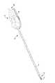
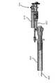
図6Aは、近位シャシ72、器具シャフト74、及び患者の組織を把持するように関節動作され得るあご部78を有する遠位エンドエフェクタ76を含む手術器具70を示す。近位シャシは、患者側カート22の出力カプラとインターフェースで接続するとともに患者側カート22の出力カプラによって駆動されるように構成された入力カプラを含む。入力カプラは、バネ組立体80の入力リンクに駆動可能に連結される。バネ組立体80は、近位シャシ72のフレーム82に取り付けられるとともに、器具シャフト74内に配置される駆動シャフトに駆動可能に連結される出力リンクを含む。駆動シャフトは、あご部78に駆動可能に連結される。図6Bは、エンドエフェクタ76のあご部78の拡大図を提供する。5A and 5B show the
(Tissue grasping end effector)
FIG. 6A shows a
図7は、図6Aのエンドエフェクタ76の分解斜視図であり、駆動シャフト84の回転運動をエンドエフェクタ76の対向するクランプあご部の関節動作に変換するために使われるクランプ機構を示す。エンドエフェクタは、上方あご部86、下方あご部88、フレーム90、上方あご部86及び下方あご部88をフレーム90に揺動可能に取り付けるためのピン92、及び駆動シャフト84に駆動可能に連結されている送りねじ機構94を含む。送りねじ機構94は、送りねじ96及び送りねじ96の回転を介してフレーム90のスロット100に沿って前進又は後退される嵌合並進移動ナット98を含む。並進移動ナット98は、上方あご部86のスロット102及び下方あご部88のスロット104と連結する逆に延びる突出部を含むので、並進移動ナット98がスロット100に沿って前進又は後退されるとき上方あご部86及び下方あご部88のピン92周りの関節動作を引き起こす。 FIG. 7 is an exploded perspective view of the
図8A及び図8Bは、図7のクランプ機構に類似するクランプ機構の動作を示す。図示された方向への駆動シャフト84の回転は、並進移動ナット98を、下方あご部88及び上方あご部86がエンドエフェクタのフレーム90に揺動可能に取り付けられるピボットピン92に向かって遠位に進ませる。図8Bに示されるように、並進移動ナット98の突出部は、上方あご部86のスロット102に係合する。ピボットピン92に向かう並進移動ナット98の遠位前進は、上方あご部を図示された方向に回転させるとともに、下方あご部88を反対方向に回転させ、したがってあご部を開かせる。同様に、ピボットピン92から離れる並進移動ナット98の近位前進は、あご部を閉じさせる。したがって、あご部は患者の組織を把持するように関節動作され得る。 8A and 8B illustrate the operation of a clamping mechanism similar to that of FIG. Rotation of the
図7、図8A、及び図8Bに示された送りねじタイプのクランプ機構は、駆動シャフトによって伝達される比較的低いトルクを比較的高いクランプ力に変換する相当な機械的利点を提供する。このような相当な機械的利点を有する機構を介して組織を過度なクランプ力にさらすことを避けるために、駆動シャフトによってクランプ機構に伝達されるトルクは制御され得る。 The feed screw type clamping mechanisms shown in FIGS. 7, 8A and 8B provide significant mechanical advantages in converting the relatively low torque transmitted by the drive shaft to a relatively high clamping force. The torque transmitted by the drive shaft to the clamping mechanism may be controlled to avoid exposing the tissue to excessive clamping forces through the mechanism having such significant mechanical advantages.
(代替エンドエフェクタ機構)
駆動シャフト84は、任意の適切なエンドエフェクタ機構を作動させるために使用され得る。例えば、駆動シャフト84は、組織吻合機構、組織切断機構、及び回転入力によって作動され得る一般的な任意の適切なエンドエフェクタ機構等、機構を作動させるために使用され得る。(Alternate end effector mechanism)
Drive
(器具シャフトのロールとエンドエフェクタの作動の切り離し)
図9は、手術器具における器具シャフトのロールとエンドエフェクタの作動の切り離しを論じるための適切な出発点を提供する。図9は、アイテム(例えば、患者の組織、縫合針等)を把持するように操作可能な関節動作されるあご部112を含むエンドエフェクタ110を示す。エンドエフェクタ110は、関節動作されるあご部112等、エンドエフェクタ110の機構を作動させるための作動機構を含む。作動機構は、駆動シャフト114と駆動可能に連結される。エンドエフェクタ110は、器具シャフト116の遠位端部に支持される。器具シャフト116は、器具シャフト116を支持する近位シャシベースに対してある回転の範囲で回転可能である。同様に、駆動シャフト114は、近位シャシベースに対してある回転の範囲で回転可能である。(Separation of tool shaft roll and end effector operation)
FIG. 9 provides a suitable starting point for discussing the decoupling of the actuation of the roll of the instrument shaft and the end effector in a surgical instrument. FIG. 9 shows an
駆動シャフト114が駆動シャフト116の回転との如何なるつながりからも独立している場合、エンドエフェクタあご部112を作動させるために使用され得る近位シャシベースに対する駆動シャフト114の回転の範囲の一部は、近位シャシベースに対する駆動シャフト116の回転の範囲によって減らされる。例えば、ベースに対する器具シャフト116の回転の範囲が2回転に等しく且つベースに対する駆動シャフト114の回転の範囲が10回転に等しい場合、エンドエフェクタ110に対する駆動シャフト114のネットの回転の範囲は8回転に等しい。言い換えると、これらの2つの独立した2回転は、組み合わされた場合、エンドエフェクタ110の作動機構に対する駆動シャフト114のゼロのネット回転を生み出すので、ベースに対する駆動シャフト114の2回転は、ベースに対する器具シャフト116の2回転によって事実上打ち消される。 If the
図10は、エンドエフェクタ作動機構を駆動させるための出力運動124を発生させるように第1の入力運動120と器具シャフトの回転122を組み合わせるための差動装置118の使用を概略的に示す。差動装置118は、近位シャシベースに対する駆動シャフト114の回転の量とエンドエフェクタ作動機構に対する駆動シャフト114の回転の対応する量との間の差を生じさせるときの器具シャフトの回転の上述の影響に対抗(相殺)するように構成され得る。例えば、差動装置118は、近位シャシベースに対する時計周りの3回転の出力運動124を生み出すように、近位シャシベースに対する時計回りの2回転の第1の入力運動120を近位シャシベースに対する時計回りの1回転の器具シャフトの運動122と組み合わせるように構成されることができ、事実上エンドエフェクタに対する時計回りの2回転の出力運動をもたらす。このような差動装置はまた、駆動シャフト114及び器具シャフト116が反対方向に回転する場合、器具シャフトの回転の上述の影響に対抗するように機能する。例えば、このような差動装置の構成を用いて、近位シャシベースに対する第1の入力運動120の時計回りの2回転は、ベースに対する器具シャフト122の反時計回りの1回転と組み合わせてベースに対する出力運動124の時計回りの1回転を生み出し、事実上エンドエフェクタに対する出力運動の時計回りの2回転の出力運動を作り出す。 FIG. 10 schematically illustrates the use of the differential 118 to combine the
差動装置が近位シャシベースに対する駆動シャフトの量とエンドエフェクタ作動機構に対する駆動シャフトの回転の対応する量との間の差を生み出す上述の器具シャフトの回転の影響の全てを実質的に相殺するように構成されることが好ましい一方、差動装置はまた、器具シャフトの回転の影響を任意の適切な程度に対抗(相殺)するように構成され得る。例えば、差動装置は、手術器具の所望の動作特性を達成するために適切であるように、上述の器具シャフトの回転の影響に、下回って対抗する、上回って対抗する、及び影響を拡大さえするように構成され得る。 A differential substantially cancels out all of the effects of the above-described tool shaft rotation to create a difference between the amount of drive shaft relative to the proximal chassis base and the corresponding amount of rotation of the drive shaft relative to the end effector actuation mechanism While preferably configured as such, the differential may also be configured to counteract the effects of instrument shaft rotation to any suitable degree. For example, the differential may counter, counter, over against, and even magnify the effects of instrument shaft rotation described above as appropriate to achieve the desired operating characteristics of the surgical instrument. Can be configured to
差動装置は、任意の適切な方法で実装され得る。例えば、差動装置は、ケーブル及びプーリを使用して実装され得る。他の例として、差動装置は、遊星ギヤボックス組立体等、伝動装置を使用して実装され得る。 The differential may be implemented in any suitable manner. For example, the differential may be implemented using cables and pulleys. As another example, the differential may be implemented using a transmission, such as a planetary gearbox assembly.
(ケーブル実装差動装置)
図11Aは、多くの実施形態による、ロボット手術器具における器具シャフトのロールとエンドエフェクタの作動を切り離すために使用されるケーブル実装差動装置130を示す。差動装置130は、近位シャシベースに対する器具シャフトの回転に回転可能に連結されるロールプーリ132、作動源に回転可能に連結されるエンドエフェクタ作動プーリ134、及びエンドエフェクタあご部作動機構に回転可能に連結される送りねじ駆動プーリ136を含む。ロールプーリ132及び送りねじ駆動プーリ136の両方に掛かる第1のケーブル138は、ロールプール132の回転に応じて送りねじ駆動プーリ136の回転を提供する。エンドエフェクタ作動プーリ134に掛かる第2のケーブル140は、第1のプーリブロック142及び第2のプーリブロック144に連結される。第1のプーリブロック142は、第1の可動プーリ146を含む。第2のプーリブロック144は、第2の可動プーリ148を含む。第1及び第2の可動プーリ146、148は第1のケーブル138が掛かる。(Cable mounting differential)
FIG. 11A illustrates a cable mounted differential 130 used to decouple actuation of the end effector and the roll of the instrument shaft in a robotic surgical instrument, in accordance with many embodiments. The differential 130 rotates to a
ロールプーリ132と送りねじ駆動プーリ136との間には、第1のケーブル138が4つの固定ガイドプーリに掛かる。これらの固定ガイドプーリは、第1のガイドプーリ150、第2のガイドプーリ152、第3のガイドプーリ154、及び第4のガイドプーリ156を含む。 Between the
図11Bは、ケーブル実装差動装置130の側面図である。ロールプーリ132は、ヘリカルギヤ158を通して器具シャフトの回転と回転可能に連結される。ロールプーリ132及びヘリカルギヤ158は、回転軸160周りに回転する。器具シャフトは、ヘリカルギヤの回転軸160に直角に配向される回転軸周りに回転する。ヘリカルギヤ158及び器具シャフトとともに回転するように取り付けられた噛み合いヘリカルギヤは、器具シャフトの回転をロールプーリ132の回転に伝達する。 FIG. 11B is a side view of cable mounted
4つの固定ガイドプーリ150、152、154、156は、第1のケーブル138の位置を水平及び垂直に拘束するように働く。第1及び第3のガイドプーリ150、154は、第1のケーブル138の重なる部分の間の垂直な分離を提供するように、第2及び第4のガイドプーリ152、156の間に配置される。第1及び第3のガイドプーリ150、154はまた、第1の可動プーリ146の移動範囲にわたって第1の可動プーリ146と第1のケーブル138との間の180度の掛かりを提供するように、水平に配置される。同様に、第2及び第4のガイドプーリ152、156もまた、第2の可動プーリ148の移動範囲にわたって第2の可動プーリ148と第1のケーブル138との間の180度の掛かりを提供するように、水平に配置される。 The four fixed guide pulleys 150, 152, 154, 156 serve to constrain the position of the
ケーブル実装差動装置130は、送りねじ駆動プーリ136の運動を生じさせるように、ロールプーリ132の運動とエンドエフェクタ作動プーリ134の運動を結合する。例えば、エンドエフェクタ作動プーリ134のどんな回転もない場合、ロールプーリ132の回転は、送りねじ駆動プーリ136の対応する回転を生じさせるので、エンドエフェクタあご部作動機構に対する送りねじ駆動プーリ136のネットの回転をもたらさない。ロールプーリ132のどんな回転もない場合、エンドエフェクタ作動プーリ134の回転は、第1及び第2の可動プーリ146、148の対応する運動を生じさせるので、送りねじ駆動プーリ136のネットの回転を生じさせる。そしてロールプーリ132及びエンドエフェクタ作動プーリ134両方の同時の回転に関しては、第1のケーブル138及び第2のケーブル140の対応する運動は、ロールプーリ132及びエンドエフェクタ作動プーリ134の回転の組み合わせである送りねじ駆動プーリ136の回転をもたらす。 The cable mounted differential 130 couples the motion of the
図12は、多くの実施形態による、ケーブル実装差動装置170を有するロボット手術器具の近位シャシの斜視図である。ケーブル実装差動装置170は、ケーブル実装差動装置130と同様に構成されるが、第1のケーブル184を水平及び垂直に拘束するために、6つの固定ガイドプーリ172、174、176、178、180、182を含む。 FIG. 12 is a perspective view of the proximal chassis of a robotic surgical instrument having a cable mounted
任意の適切なケーブル実装差動装置が使用され得る。例えば、ケーブル実装差動装置130の変形形態では、第1のケーブル138はエンドエフェクタ作動プーリ134によって駆動されるとともに第2のケーブル140はロールプーリ132によって駆動される。
(ギヤ実装差動装置)
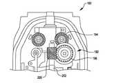
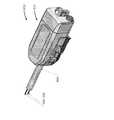
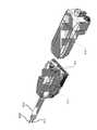
図13は、多くの実施形態による、ギヤ実装差動装置192を含むロボット手術器具の近位シャシ190の斜視図である。ギヤ実装差動装置192は、サンギヤ、キャリアに連結された遊星ギヤ、及びリングギヤを含む遊星ギヤ組立体を含む。キャリアは、入力シャフトを通して近位シャシの入力カプラと回転可能に連結される。入力シャフトは、入力カプラに一直線に並べられるとともに器具シャフトと直交する。サンギヤは、ヘリカルギヤ194、196を通して器具シャフト116の回転と回転可能に連結される。キャリア及びサンギヤの回転は、リングギヤの回転をもたらす。リングギヤは、ヘリカルギヤ198、200、出力シャフト202、及び器具シャフト116の内部に通された駆動シャフトを通して、エンドエフェクタ作動機構に回転可能に連結される。図14は、近位シャシ190及びギヤ実装差動装置192の平面図を示す。そして、図15は、近位シャシ190及びギヤ実装差動装置192の側面図を示す。Any suitable cable mounted differential may be used. For example, in a variation of cable mounted
(Gear mounted differential)
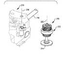
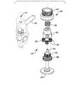
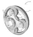
FIG. 13 is a perspective view of a
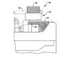
図16及び図17は、多くの実施形態による、ギヤ実装差動装置210の詳細を示す分解図である。ギヤ実装差動装置210は、遊星ギヤボックス組立体212を含む。図16は、入力シャフト116を有するロボット手術器具の近位シャシに設置される所から横に移動されたギヤ実装差動装置210並びに取付けられた入力シャフト及び入力カプラ214を示す。設置中心線218及びギヤ実装差動装置210の中心軸220は設置位置からのオフセットを示す。 Figures 16 and 17 are exploded views showing details of the gear mounted
図17は、ギヤ実装差動装置210、入力シャフト、及び入力カプラ214の分解斜視図である。差動装置210は、遊星ギヤ224に連結されたキャリア222、入力ギヤ228によって回転駆動されるサンギヤ226、内部リングギヤ及び外部ヘリカル出力ギヤ232を有するリングギヤ部材230、を含む。キャリア222は、入力シャフト234に回転可能に連結されるとともに入力シャフト234によって駆動され、入力シャフト234は、入力カプラ214に回転可能に連結されるとともに入力カプラ214によって駆動される。入力カプラ214は、近位シャシ216がロボットアームに取付けられる場合、手術ロボットのロボットアームの対応する出力カプラと接続するとともに出力カプラによって回転駆動される。キャリア222の回転は中心軸220周りの遊星ギヤ224の中心線の回転をもたらす。入力ギヤ228は、入力シャフト116の回転と回転連結される。中心軸220周りのサンギヤ226及び遊星ギヤ224の中心線の組み合わされた回転は、中心軸220周りのリングギヤ部材230の対応する回転をもたらす。リングギヤ部材230は、外部ヘリカル出力ギヤ232を通してエンドエフェクタ作動機構に駆動連結される。 FIG. 17 is an exploded perspective view of the gear mounted
ギヤ実装差動装置210は、キャリア222と近位シャシ216との間に連結されたトーションバネ236を含む。トーションバネは、ロボットアームの作動源とキャリアとの間の分離の後でキャリアを所定の位置に戻すので、エンドエフェクタ作動機構を所定の配置に戻す。 Gear mounted differential 210 includes a
動作において、ギヤ実装差動装置210は上述の差動装置118と同様に動作する。既知のアプローチを通じて追加的な伝動装置が器具シャフト116と外部ヘリカル出力ギヤ232との間の方向及び回転速度の差を相殺するために使用され得る。
(例示的な遊星ギヤボックスのパラメータ)
以下の式は、サンギヤ226、キャリア222、及びリングギヤ部材230の回転の間の関係を提供する。In operation, gear mounted differential 210 operates in the same manner as differential 118 described above. Additional transmissions may be used to offset the difference in direction and rotational speed between the
(Example planetary gearbox parameters)
The following equation provides the relationship between the rotation of
(2+n)ωa+nωs−2(1+n)ωC=0 式(1)
ここで、n=Ns/Np (遊星ギヤボックスに関する形状係数)
Ns=サンギヤの歯数
NP=遊星ギヤのギヤの歯数
ωa=リングギヤ部材(「環」としても知られる)の角速度
ωS=サンギヤの角速度
ωC=キャリアの角速度、である。(2 + n) ωa + nωs −2 (1 + n) ωC = 0 formula (1)
Where n = Ns / Np (shape factor related to the planetary gear box)
Ns = number of teeth of sun gear NP = number of teeth of planetary gear ωa = angular velocity of ring gear member (also known as "ring") ωS = angular velocity of sun gear ωC = angular velocity of carrier
式(1)に示されるように、リングギヤ部材230の角速度は、サンギヤ226の角速度及びキャリア222の角速度の線形結合である。したがって、(サンギヤ226が器具シャフト116の回転によって回転駆動され、キャリア222が入力カプラ214によって回転駆動され、リングギヤ部材230がエンドエフェクタ作動機構に回転連結される)ギヤ実装差動装置210では、器具シャフト116の回転は、リングギヤ部材230の対応する追加的な回転をもたらすので、エンドエフェクタ作動機構の作動から器具シャフトの回転を切り離す。 As shown in equation (1), the angular velocity of the
以下のパラメータは、ギヤ実装差動装置210の遊星ギヤボックスの例示的な構成を提供する。 The following parameters provide an exemplary configuration of the planetary gearbox of gear mounted
Ns=24 NP=12 n=Ns/NP=2
Na=Ns+2NP=48 リングギヤの歯数
DP=64 ギヤの歯数/ピッチ円直径(歯/インチ)
PDs=Ns/DP=0.375 インチ−サンギヤのピッチ円直径
PDP=NP/DP=0.1875 インチ−遊星ギヤのピッチ円直径
PDa=Na/DP=0.75 インチ−リングギヤ部材のリングギヤのピッチ円直径
Ns = 24 NP = 12 n = Ns / NP = 2
Na = Ns +2 NP = 48 Number of teeth of ring gear DP = 64 Number of teeth of gear / pitch circle diameter (tooth / inch)
PDs = Ns / DP = 0.375 inch-sun gear pitch circle diameter PDP = NP / DP = 0.1875 inch-planetary gear pitch circle diameter PDa = Na / DP = 0.75 inch- Pitch circle diameter of ring gear of ring gear member
ゼロのキャリア角速度(入力カプラ214を通した回転入力が無いものに対応する)のために、式(1)は、次のように変えられる。 For a zero carrier angular velocity (corresponding to one without rotational input through input coupler 214), equation (1) is changed as follows.
(2+n)ωa+nωs=0 式(1)でωC=0
上述の例示的な遊星ギヤボックスのパラメータに関して、n=2であり、
リングギヤ部材の角速度(ωa)とサンギヤの角速度(ωS)との間の以下の関係を作り出す。
(2 + n) ωa + n ωs = 0 In the equation (1), ωC = 0
For the parameters of the exemplary planetary gearbox described above, n = 2,
It produces the following relationships between the ring gear member of the angular velocity (omegaa) and the sun gear of the angular velocity (ωS).

サンギヤ226とリングギヤ部材230との間の回転方向の差を相殺するために及びエンドエフェクタ作動機構に回転連結された駆動シャフトの回転の器具シャフト116のものと等しい回転量を実現するために、既知のアプローチを使用する追加的な伝動装置が、器具シャフト116とサンギヤ226との間に、及び/又はリングギヤ部材230とエンドエフェクタ作動機構に回転連結された駆動シャフトとの間に使用され得る。
It is known to offset the difference in rotational direction between the
(手術用組立体への適用)
本願に開示された手術用組立体は、任意の適切な応用に用いられ得る。例えば、本願に開示された手術用組立体は、他の手術器具で、手動式又は動力式で、携帯式又はロボット式で、直接制御式又は遠隔操作式で、観血式又は低侵襲(単一又は複数ポート)手術のために、用いられ得る。このような器具の例は、(例えば、グリップ制御機能、構成要素配向制御機能、構成要素位置決め機能等のための)トルク作動入力を受ける遠位構成要素を持つものを含む。図解の非限定的な例は、吻合、切断、組織溶融、撮像装置の向き及び位置の制御、高い力での把持、生検、エンドエフェクタ及び向きの制御を含む遠隔操作式又は携帯式器具を含む。(Application to surgical assembly)
The surgical assembly disclosed herein may be used in any suitable application. For example, the surgical assembly disclosed herein may be other surgical instruments, manual or powered, portable or robotic, direct control or remote control, invasive or minimally invasive One or more ports) can be used for surgery. Examples of such instruments include those with distal components that receive torque actuated input (eg, for grip control functions, component orientation control functions, component positioning functions, etc.). Non-limiting examples of illustrations include teleoperated or portable instruments including anastomosis, cutting, tissue melting, control of imaging device orientation and position, high force grip, biopsy, end effector and orientation control. Including.
(器具シャフトのロールとエンドエフェクタの作動を切り離す方法)
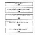
図18は、多くの実施形態による、器具シャフトの回転を手術器具シャフトによって支持されたエンドエフェクタの機構に駆動連結された駆動シャフトの回転から切り離すための方法250の動作を示す。方法250は、例えば、上述の差動装置118、ケーブル実装差動装置130、ケーブル実装差動170、及びギヤ実装差動装置192のいずれか等、任意の適切な差動装置を使用して、実施され得る。方法250は、所望のエンドエフェクタ配置に関連する第1の入力運動を発生させるステップ(動作252)、ベースに隣接する近位端部とエンドエフェクタを支持する遠位端部との間に延びる手術器具シャフトをベースに対して回転させるステップ(動作254)、ベースに対する器具シャフトの回転に応じて第2の入力運動を発生させるステップ(動作256)、出力運動を発生させるために第1及び第2の入力運動を結合させるステップ(258)、及び出力運動に応じて駆動シャフトを回転させる(動作260)を含む。多くの実施形態において、第1及び第2の入力運動は、第1の入力運動がゼロである場合、手術器具に対する駆動シャフトの回転が実質的に生じないように結合される。(How to decouple the operation of the instrument shaft roll and the end effector)
FIG. 18 illustrates the operation of the
図19は、本願に記載されたもののいずれかのような、ケーブル実装差動装置を使用することによって方法250を実施するために使用され得る動作を示す。動作は、ベースに対する手術器具シャフトの回転に応じて第1のケーブルを動かすステップ(動作262)、第2のケーブルを動かすステップ(動作264)、第2のケーブルの動きに応じて第1のプーリ及び第2のプーリを動かすステップ(動作266)、第1のケーブルを第1及び第2のプーリのそれぞれに掛けるステップ(動作268)、及び第1のケーブルの動きに応じて駆動シャフトを回転させるステップ(動作270)を含む。多くの実施形態において、第1のケーブルは、第1及び第2のプーリに、それぞれのプーリの約180度の扇形に渡って掛けられる。 FIG. 19 illustrates operations that may be used to implement the
図20は、本願に記載されたもののいずれかのような、ケーブル実装差動装置を使用することによって方法250を実施するために使用され得る動作を示す。動作は、第1のケーブルを動かすステップ(動作272)、ベースに対する手術器具シャフトの回転に応じて第2のケーブルを動かすステップ(動作274)、第2のケーブルの動きに応じて第1のプーリ及び第2のプーリを動かすステップ(動作276)、第1のケーブルを第1及び第2のプーリのそれぞれに掛けるステップ(動作278)、及び第1のケーブルの動きに応じて駆動シャフトを回転させるステップ(動作280)を含む。多くの実施形態において、第1のケーブルは、第1及び第2のプーリに、それぞれのプーリの約180度の扇形に渡って掛けられる。 FIG. 20 illustrates operations that may be used to implement
図21は、本願に記載されたもののいずれかのような、ギヤ実装差動装置を使用することによって方法250を実施するために使用され得る動作を示す。動作は、第1の入力運動に応じて差動ギヤ組立体の第1の入力リンクを回転させるステップ(動作282)、第2の入力運動に応じて差動ギヤ組立体の第2の入力リンクを回転させるステップ(動作284)、及び差動ギヤ組立体の出力リンクの回転に応じて駆動シャフトを回転させるステップ(動作286)を含む。 FIG. 21 illustrates operations that may be used to implement
(方法の適用)
本願に開示された手術用組立体は、任意の適切な応用に用いられ得る。例えば、本願に開示された手術用組立体は、他の手術器具で、手動式又は動力式で、携帯式又はロボット式で、直接制御式又は遠隔操作式で、観血式又は低侵襲(単一又は複数ポート)手術のために、用いられ得る。このような器具の例は、(例えば、グリップ制御機能、構成要素配向制御機能、構成要素位置決め機能等のための)トルク作動入力を受ける遠位構成要素を持つものを含む。図解の非限定的な例は、吻合、切断、組織溶融、撮像装置の向き及び位置の制御、高い力での把持、生検、エンドエフェクタ及び向きの制御を含む遠隔操作式又は携帯式器具を含む。(Apply the method)
The surgical assembly disclosed herein may be used in any suitable application. For example, the surgical assembly disclosed herein may be other surgical instruments, manual or powered, portable or robotic, direct control or remote control, invasive or minimally invasive One or more ports) can be used for surgery. Examples of such instruments include those with distal components that receive torque actuated input (eg, for grip control functions, component orientation control functions, component positioning functions, etc.). Non-limiting examples of illustrations include teleoperated or portable instruments including anastomosis, cutting, tissue melting, control of imaging device orientation and position, high force grip, biopsy, end effector and orientation control. Including.
(回転可能なシャフト内の駆動シャフト)
図22は、回転可能なメインシャフト内に2つのオフセット駆動シャフトを有するロボット組立体370を図式的に示す。ロボット組立体370は、回転可能なメインシャフト374の遠位端部に連結されるエンドエフェクタ372、並びにメインシャフト74及びエンドエフェクタ372の両方に連結された作動組立体376を含む。(Drive shaft in rotatable shaft)
FIG. 22 schematically illustrates a
エンドエフェクタ372は、エンドエフェクタベース、第1の作動機構378、第2の作動機構380、及び制御ケーブル機構382を含む。エンドエフェクタベースは、回転可能なメインシャフト374に旋回可能に連結される。第1の作動機構378及び第2の作動機構380は、シャフト駆動型であり、さまざまなエンドエフェクタ特徴及び/又はデバイス、例えば、クランピング機能、可動式切断機能、切断及び吻合機能、又はシャフト駆動型機構で作動及び/又は関節動作することができる別の好適なエンドエフェクタ機能及び/又は装置を、作動及び/又は関節動作させるために使用することができる。制御ケーブル機構382もまた、さまざまなエンドエフェクタ機能及び/又は装置、特に、迅速な反応が望ましいもの、例えば、把持機能、エンドエフェクタベースをメインシャフトに対して関節動作させるために使用されるエンドエフェクタベースリストに対するメインシャフト、又は1つ以上の制御ケーブルを介して作動及び/又は関節動作することができる別の好適な機能及び/又は装置を、作動及び/又は関節動作させるために使用することができる。 The
エンドエフェクタベースは、メインシャフト回転軸周りのメインシャフト374の回転がエンドエフェクタベースの対応する回転を生じさせるように、回転可能なメインシャフト374と連結される。上述のように、メインシャフト374を独立して回転させる能力は、非回転メインシャフトに対するエンドエフェクタの操作性の増大を提供し、それは、ある特定の手術中、例えば、ある特定の低侵襲手術に有益になり得る。エンドエフェクタベースはまた、追加的なエンドエフェクタの操作性を提供する適切なリスト機構384を用いて、回転可能なメインシャフト374に連結することができる。 The end effector base is coupled to the rotatable
2つの駆動シャフトがエンドエフェクタシャフト駆動型作動機構を駆動するために使用される。第1の駆動シャフト386は、メインシャフト回転軸からオフセットされる第1の駆動シャフト回転軸周りの回転のために取付けられる。第1の駆動シャフト386は第1の作動機構378と動作可能に連結される。同様に、第2の駆動シャフト388は、メインシャフト回転軸からオフセットされる第2の駆動シャフト回転軸周り回転のために取付けられる。第2の駆動シャフト388は第2の作動機構380と動作可能に連結される。 Two drive shafts are used to drive the end effector shaft driven actuation mechanism. The
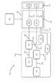
作動組立体376は、回転可能なメインシャフト374、第1の駆動シャフト386、第2の駆動シャフト388、及び制御ケーブル382と連結される。回転可能なメインシャフト374は、作動組立体376のベースに対する回転のために装着される。作動組立体376は、ベースに対する回転可能なメインシャフト374の回転を生じるように動作可能である。作動組立体376はまた、ベースに対する回転可能なメインシャフト374の回転、回転可能なメインシャフト374に対する第1の駆動シャフト386の回転、及び回転可能なメインシャフト374に対する第2の駆動シャフト388の回転の任意の組み合わせを発生させるように動作可能である。そのため、第1の作動機構378及び/又は第2の作動機構380は、回転可能なメインシャフト374の回転と独立して及び/又は同時に、作動され得る。 The actuation assembly 376 is coupled to the rotatable
作動組立体376は、ベースに対する回転可能なメインシャフト374の回転中でさえ、第1の駆動シャフト386及び第2の駆動シャフト388が、回転可能なメインシャフト374に対して、独立して回転することができる、上述の機能性を提供するように構成される。作動組立体376は、メインシャフトエンコーダ392及びメインシャフトインターフェース394と連結されたメインシャフトモータ390、第1のエンコーダ398及び第1のインターフェース400と連結された第1のモータ396、第2のエンコーダ404及び第2のインターフェース406と連結された第2のモータ402、並びに制御ケーブルエンコーダ410及び制御ケーブルインターフェース412に連結された制御ケーブルモータ408を含む。メインシャフトインターフェース394は、回転運動をメインシャフトモータ390から回転可能なメインシャフト374に伝達するように、回転可能なメインシャフト374と連結される。メインシャフトモータ390は、伝達された回転運動が、ベースに対する回転可能なメインシャフト374の回転をもたらすように、ベースと固定して連結され得る。メインシャフトエンコーダ392は、メインシャフトモータ390、メインシャフトインターフェース394、及び/又は回転可能なメインシャフト374の向きを測定し、測定された向きコントローラに提供するようにコントローラ(図22に図示せず)と連結され得る。第1のインターフェース400は、回転可能なメインシャフト374の任意の向き及び/又は回転運動中に、回転運動を第1のモータ396から第1の駆動シャフト386に伝達するために動作可能になるように、第1の駆動シャフト386に連結される。第1のエンコーダ398は、第1のモータ396、第1のインターフェース400、及び/又は第1の駆動シャフト386の向きを測定し、測定された向きをコントローラに提供するように、コントローラと連結され得る。第2のインターフェース406は、回転可能なメインシャフト374の任意の向き及び/又は回転運動中に、回転運動を、第2のモータ402から第2の駆動シャフト388に伝達するために動作可能になるように、第2の駆動シャフト388と連結される。第2のエンコーダ404は、第2のモータ402、第2のインターフェース406、及び/又は第2の駆動シャフト388の向きを測定し、測定された向きをコントローラに提供するように、コントローラと連結され得る。制御ケーブルインターフェース412は、制御ケーブル機構382と動作可能に連結される制御ケーブル414と連結される。制御ケーブル414は、例えば、回転可能なメインシャフト374の回転に依る制御ケーブルの長さの変化を最小化するようにメインシャフト回転軸の近傍にルーティングされることによって、及び(例えば、ケーブルとケーブルのこすれることに耐える構成を有することによって)メインシャフト374のいくつかの回転配向をもたらし得る制御ケーブルの任意のねじれ及び/又は制御ケーブル間のねじれに耐えるように構成されることによって、回転可能なメインシャフト374の回転配向範囲を許容するようにルーティングされ得る。制御ケーブルエンコーダ410は、制御ケーブルモータ408及び/又は制御ケーブルインターフェース412の向きを測定し、測定された向きをコントローラに提供するようにコントローラに連結され得る。 The actuation assembly 376 rotates independently of the
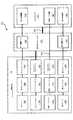
図23は、多くの実施形態による、コントローラ416を持つロボットアセンブリ370の構成要素の統合を図示する簡略化されたブロック図である。コントローラ416は、バスサブシステム420を介して、多くの周辺デバイスと通信する少なくとも1つのプロセッサ418を含む。これらの周辺デバイスは、典型的には、記憶サブシステム422を含む。 FIG. 23 is a simplified block diagram illustrating the integration of the components of a
記憶サブシステム422は、コントローラ416の機能性を提供する基本的プログラミング及びデータ構造を保持する。上述のロボット組立体の機能性を実装するためのソフトウエアモジュールは、典型的には、記憶サブシステム422内に記憶される。記憶サブシステム422は、典型的には、メモリサブシステム424及びファイル記憶サブシステム426を含む。
メモリサブシステム424は、典型的には、プログラム実行中に命令及びデータを記憶するためのメインランダムアクセスメモリ(RAM)428及び固定命令が記憶される読み出し専用メモリ(ROM)430を含む、幾つかのメモリを含む。 The
ファイル記憶サブシステム426は、プログラム及びデータファイルのための永続性(不揮発性)記憶装置を提供し、ハードドライブ、ディスクドライブ、又はフラッシュメモリ等他の不揮発性メモリを含み得る。入力デバイス、例えば、ディスクドライブを使用して、上述のソフトウエアモジュールを入力するために使用され得る。或いは、他の既知の構成、例えば、USBポートが、ソフトウエアモジュールを入力するために使用され得る。
この文脈では、「バスサブシステム」という用語は、種々の構成要素及びサブシステムが意図されるように互いに通信させるための任意の機構を含むように包括的に使用される。バスサブシステム420を、単一のバスとして概略的に示されるが、典型的なシステムは、ローカルバス及び1つ又は複数の拡張バス(例えば、ADB、SCSI、ISA、EISA、MCA、NuBus、又はPCI)等の多くのバス、並びにシリアルおよびパラレルポートを有する。 In this context, the term "bus subsystem" is used generically to include any mechanism for causing the various components and subsystems to communicate with one another as intended. Although
コントローラ416は、入力制御デバイス36(図2に示す)からの信号、並びにメインシャフトエンコーダ392、第1のエンコーダ398、第2のエンコーダ404、及び制御ケーブルエンコーダ410からの信号を含む、様々な受信信号に応じて、ロボットアセンブリ370の構成要素を制御する。制御される構成要素は、メインシャフトモータ390、第1のモータ396、第2のモータ402、及び制御ケーブルモータ408を含む。デジタル/アナログ変換器等の追加的な構成要素(図示せず)は、構成要素をコントローラ416とインターフェースするために使用され得る。
図24は、多くの実施形態による、ロボット手術システム内のロボット手術ツール432の統合を示す簡略されたブロック図である。ツール432は、近位ツールシャシ434とインターフェースするように構成されたツールインターフェースを有するマニピュレータ436上に解放可能に取り付け可能になるように構成された近位ツールシャシ434を含む。ツール432はさらに、上述のように、メインシャフトモータによって回転させられるとき、近位ツールシャシ434に対して回転するように取付けられる細長いメインシャフト374を含む。エンドエフェクタ440は、メインシャフトとともに回転するように、メインシャフト374の遠位端と連結される。主制御システム442は、マニピュレータ436と動作可能に連結される。補助制御システム444はまた、マニピュレータ436と動作可能に連結され得る。主制御システム442及び補助制御システム444の組み合わせは、マニピュレータ436を介するツール432の全ての可能な関節運動を制御するために使用され得る。例えば、補助制御システム444は、第1の駆動シャフトの回転及び第2の駆動シャフトの回転のために駆動モータを制御し得る。主制御システム442は、メインシャフトの回転のための駆動モータ、及び1つ又は複数の制御ケーブル駆動モータを制御し得る。この様な補助コントローラは、独立して回転するメインシャフト内にルーティングされた1つ又は複数のオフセット駆動シャフトを有する現在開示されるロボットツールの使用を可能にするように、既存のロボット手術システム構造を補完するために使用され得る。
(意図されたにメインシャフトの回転を避けるためにエンドエフェクタ及びエンドエフェクタを支持するメインシャフトに駆動モータを連結すること)
図25は、多くの実施形態による、エンドエフェクタ回転機構の作動中、メインシャフト/エンドエフェクタ組立体の意図されない回転を避けるために、エンドエフェクタ回転機構を作動するために使用される駆動モータがメインシャフト/エンドエフェクタ組立体に連結される手術用組立体500を図式的に示す。手術用組立体500は、ベース(例えば、図24に示されたマニピュレータ436)に回転可能に取り付けられるメインシャフト/エンドエフェクタ組立体502、ベースに対してメインシャフト/エンドエフェクタ組立体502を回転駆動するメインシャフト駆動装置504、並びに作動トルクをエンドエフェクタ回転機構に及び相殺トルク507をメインシャフト/エンドエフェクタ組立体502に提供するようにメインシャフト/エンドエフェクタ組立体502に回転可能に連結される反作用作動組立体506を含む。FIG. 24 is a simplified block diagram illustrating the integration of
(Connecting the drive motor to the end effector and the main shaft supporting the end effector to avoid intended rotation of the main shaft)
FIG. 25 illustrates that, according to many embodiments, the drive motor used to actuate the end effector rotation mechanism is main to avoid unintended rotation of the main shaft / end effector assembly during actuation of the end effector rotation mechanism. 7 schematically illustrates a
メインシャフト/エンドエフェクタ組立体502は、ベースに回転可能に取り付けられるとともにメインシャフト駆動装置504によって回転駆動されるメインシャフト508、及びメインシャフト508によって支持されるエンドエフェクタ510を含む。エンドエフェクタ510は、第1の回転機構512及び第2の回転機構514を含む。第1及び第2の回転機構512、514は、例えば、クランプあご部、吻合装置、切断装置、及び同様のもの等、エンドエフェクタ構成要素を関節動作させるために使用され得る。 The main shaft /
低侵襲手術ツールに課される寸法の制約のために、作動トルクを第1及び第2の回転機構512、514にメインシャフト/エンドエフェクタ組立体502の外側にあるソースから供給することが望ましい。しかし、このような構成では、第1及び第2の回転機構512、514が、メインシャフト/エンドエフェクタ組立体502によって支持される、エンドエフェクタ510の一部であるので、作動トルクが外側ソースから第1及び第2の回転機構512、514に伝達されるとき、伝達された作動トルクの一部又はすべてがメインシャフト508によって縮小され得る。メインシャフト/エンドエフェクタ組立体502によって縮小される作動トルクはまた、メインシャフト508によって縮小され得る。結果として、メインシャフト駆動装置504は、メインシャフト/エンドエフェクタ組立体502によって縮小される十分な量のトルクを介してバックドライブ可能であり得る。言い換えると、メインシャフト駆動装置504は、メインシャフト/エンドエフェクタ組立体502がバックドライビング閾値を超えるネットトルク(引き起こされた摩擦に打ち勝つのに必要な任意のトルクを含む)を受けるときメインシャフト/エンドエフェクタ組立体502がメインシャフト駆動装置をバックドライブさせるように且つメインシャフト/エンドエフェクタ組立体502がバックドライビング閾値より下のネットトルクを受けるときメインシャフト駆動装置をバックドライブさせないような、バックドライビングトルク閾値を有し得る。そして、例えば、付随するコスト、サイズ、重量、付随する有害な特性、及び/又は費用を避けるために、トルクブレーキ、逆転できない伝動装置、その他同様のもの等、メインシャフト508によるメインシャフト駆動装置504の回転駆動(バックドライビングとしても知られる)を防ぐある機構の使用を避けることも望ましい。 Due to the dimensional constraints imposed on minimally invasive surgical tools, it may be desirable to supply actuation torque to the first and
手術用組立体500では、反作用作動組立体506は、第1及び第2の回転機構512、514に伝達される作動トルクを発生させる外部ソースである。反作用作動組立体506はまた、メインシャフト504のバックドライビングを防ぐようにメインシャフト508に伝達されるバランストルクを発生させる。反作用作動組立体506は、第1の駆動モータ516、第2の駆動モータ518、第1の変速装置520、第1の回転カップリング522、第2の変速装置524、及び第2の回転カップリング526を含む。 In the
第1の駆動モータ516は、第1の変速装置520及び第1の回転カップリング522を介して第1の駆動機構512及びメインシャフト508に回転可能に連結される。第1の駆動モータ516は、第1の変速装置の第1の入力リンク528に回転可能に連結されるとともに第1の入力トルクを第1の入力リンク528に伝達する。第1の変速装置520は、第1の入力リンク528と第1の変速装置520の第1の出力リンク530との間に第1のギヤ比を提供する。第1の出力リンク530は、第1の回転機構512に回転可能に連結される。第1の回転カップリング522は、第1の変速装置520の第1のベースリンク532とメインシャフト508との間に接続される。第1の回転カップリング522は、第1のベースリンク532とメインシャフト508との間に第2のギヤ比を提供する。第1のベースリンク532は、回転接地されていない(例えば、メインシャフト508が回転可能に取り付けられるベースに回転接地されていない)。 The
第1の変速装置520によって与えられる第1のギヤ比は、第1の出力リンク530が第1の入力トルクを超えるトルクを伝達するようなものより十分大きい。第1の変速装置520の第1のベースリンク532は回転接地されていないので、第1の出力リンク530によって伝達されるトルクと第1の入力トルクとの間の差は、第1のベースリンク532から第1の回転カップリング522に伝達される反対方向のトルクによってバランスされる。多くの実施形態では、第1のギヤ比は、第1の出力リンク530によって伝達されるトルク及び第1のベースリンク532から第1の回転カップリング522に伝達される反対方向のトルクが略等しい大きさを有するようなものより著しく大きい。例えば、第1のギヤ比が9対1である実施形態では、第1の出力リンク530によって伝達されるトルクは、第1の入力トルクの9倍である。そして、第1のベースリンク532から第1の回転カップリング522に伝達される反対方向のトルクは、第1の入力トルクの大きさの8倍の大きさを有する。 The first gear ratio provided by the
第1の回転カップリング522によって提供される第2のギヤ比は、第1の回転カップリング522によるメインシャフト508に伝達されるトルクが、メインシャフト/エンドエフェクタ組立体502によってメインシャフト駆動装置504の回転駆動を抑止するように第1の出力リンク530によってメインシャフト/エンドエフェクタ組立体502に伝達されるトルクを十分バランスさせるように、選択される。メインシャフト駆動装置504が非ゼロバックドライビングトルク閾値を有する場合、第2のギヤ比は、ある範囲のギヤ比から選択され得るとともに、メインシャフト/エンドエフェクタ組立体502によるメイン駆動装置の回転駆動の抑止を依然としてもたらすことができる。理想的には、第2のギヤ比は、第1の回転カップリングによってメインシャフトに伝達されるトルクが第1の出力リンク530によってメインシャフト/エンドエフェクタ組立体502に伝達されるトルクをバランスさせるように選択される。図9には示されていないが、第1の変速装置520の第1の出力リンク530は、メインシャフト/エンドエフェクタ組立体502に直接回転連結される必要はないが、代わりに第1の出力リンク530とメインシャフト/エンドエフェクタ組立体502との間に非単一ギヤ比を提供するような方法で連結され得る。このような非単一ギヤ比が存在する場合、第1の回転カップリング522によって提供される第2のギヤ比は、追加的な非単一ギヤ比を相殺するように構成され得る。 The second gear ratio provided by the first
同様な方法で、第2の駆動モータ518は、第2の変速装置524及び第2の回転カップリング526を介して第2の駆動機構514及びメインシャフト508に回転可能に連結される。第2の駆動モータ518は、第2の変速装置の第2の入力リンク534に回転可能に連結されるとともに第2の入力トルクを第2の入力リンク534に伝達する。第2の変速装置524は、第2の入力リンク534と第2の変速装置524の第2の出力リンク536との間に第3のギヤ比を提供する。第2の出力リンク536は、第2の回転機構514に回転可能に連結される。第2の回転カップリング536は、第2の変速装置524の第2のベースリンク538とメインシャフト508との間に接続される。第2の回転カップリング526は、第2のベースリンク538とメインシャフト508との間に第4のギヤ比を提供する。第2のベースリンク538は、回転接地されていない(例えば、メインシャフト508が回転可能に取り付けられるベースに回転接地されていない)。 In a similar manner, the
第2の変速装置524によって与えられる第3のギヤ比は、第2の出力リンク536が第2の入力トルクを超えるトルクを伝達するようなものより十分大きい。第2の変速装置524の第2のベースリンク538は回転接地されていないので、第2の出力リンク536によって伝達されるトルクと第2の入力トルクとの間の差は、21のベースリンク538から第2の回転カップリング526に伝達される反対方向のトルクによってバランスされる。多くの実施形態では、第3のギヤ比は、第2の出力リンク538によって伝達されるトルク及び第2のベースリンク538から第2の回転カップリング526に伝達される反対方向のトルクが略等しい大きさを有するようなものより著しく大きい。例えば、第3のギヤ比が9対1である実施形態では、第2の出力リンク536によって伝達されるトルクは、第2の入力トルクの9倍である。そして、第2のベースリンク538から第2の回転カップリング526に伝達される反対方向のトルクは、第2の入力トルクの大きさの8倍の大きさを有する。 The third gear ratio provided by the
第2の回転カップリング526によって提供される第4のギヤ比は、第2の回転カップリング526によってメインシャフト508に伝達されるトルクが、メインシャフト/エンドエフェクタ組立体502によるメインシャフト駆動装置504の回転駆動を抑止するように第2の出力リンク536によってメインシャフト/エンドエフェクタ組立体502に伝達されるトルクを十分バランスさせるように、選択される。メインシャフト駆動装置504が非ゼロバックドライビングトルク閾値を有する場合、第4のギヤ比は、ある範囲のギヤ比から選択され得るとともに、メインシャフト/エンドエフェクタ組立体502によるメイン駆動装置の回転駆動の抑止を依然としてもたらすことができる。理想的には、第4のギヤ比は、第2の回転カップリングによってメインシャフトに伝達されるトルクが第2の出力リンク536によってメインシャフト/エンドエフェクタ組立体502に伝達されるトルクをバランスさせるように選択される。図25には示されていないが、第2の変速装置524の第2の出力リンク536は、メインシャフト/エンドエフェクタ組立体502に直接回転連結される必要はないが、代わりに第2の出力リンク536とメインシャフト/エンドエフェクタ組立体502との間に非単一ギヤ比を提供するような方法で連結され得る。このような非単一ギヤ比が存在する場合、第2の回転カップリング524によって提供される第4のギヤ比は、追加的な非単一ギヤ比を相殺するように構成され得る。 The fourth gear ratio provided by the second
第1及び第2の出力リンクは第1及び第2の回転機構512、514にそれぞれ直接回転連結され得る一方、メインシャフト/エンドエフェクタ組立体502は、第1の出力リンク530と第1の回転機構512に回転連結される第1の駆動シャフト542との間にギヤ比を提供する第1のギヤ組立体540、及び第2の出力リンク536と第2の回転機構514に回転連結される第2の駆動シャフト546との間にギヤ比を提供する第2のギヤ組立体544を含む。第1及び第2のギヤ組立体540、544の両方に関して、それらの入力と出力との間のトルク差はメインシャフト508に反応され得る。第1及び第2のギヤ組立体540、544によって提供されるギヤ比にかかわらず、第1及び第2のギヤ組立体540、544はメインシャフト/エンドエフェクタ組立体502の一部であるため、第1及び第2のギヤ組立体540、544の非単一ギヤ比によって発生する如何なるトルク差も、第1及び第2の回転機構512、514に伝達されるトルクであるように、メインシャフト508によって反応される。結果として、第1及び第2のギヤ組立体540、544のギヤ比は、第1及び第2の出力リンク530、536によってメインシャフト/エンドエフェクタ組立体502に伝達される作動トルクを相殺するように使用される反作用トルク507の大きさに対して反作用作動組立体506の構成(例えば、ギヤ比)に影響を与えない。 The first and second output links may be rotationally coupled directly to the first and
反作用作動組立体506を介してメインシャフト508に伝達される反作用トルクは、メインシャフト504の回転駆動を抑止する間、第1及び第2の出力リンク530、536を介してメインシャフト/エンドエフェクタ組立体502に伝達されるトルクは、メインシャフト駆動装置504のバックドライビングトルク閾値を越え得る。反作用トルクの大きさが、第1及び第2の出力リンク530、536によってメインシャフト/エンドエフェクタ組立体502に伝達されるトルクがバックドライビングトルク閾値を越えるときでさえメインシャフト駆動装置504のバックドライビングトルク閾値より小さいネットトルクの大きさだけ、第1及び第2の出力リンク530、536によってメインシャフト/エンドエフェクタ組立体502に伝達されるトルクの大きさと異なるように、反作用作動組立体506は構成される。好ましくは、第1及び第2の出力リンク530、536によってメインシャフト/エンドエフェクタ組立体502に伝達されるトルクがバックドライビングトルク閾値を越えるときでさえ、ネットトルクの大きさは、バックドライビングトルク閾値の50パーセントより小さい。より好ましくは、第1及び第2の出力リンク530、536によってメインシャフト/エンドエフェクタ組立体502に伝達されるトルクがバックドライビングトルク閾値を越えるときでさえ、ネットトルクの大きさは、バックドライビングトルク閾値の25パーセントより小さい。さらにより好ましくは、第1及び第2の出力リンク530、536によってメインシャフト/エンドエフェクタ組立体502に伝達されるトルクがバックドライビングトルク閾値を越えるときでさえ、ネットトルクの大きさは、バックドライビングトルク閾値の10パーセントより小さい。そして理想的には、第1及び第2の出力リンク530、536によってメインシャフト/エンドエフェクタ組立体502に伝達されるトルクがバックドライビングトルク閾値を越えるときでさえ、ネットトルクの大きさは、バックドライビングトルク閾値の2パーセントより小さい。例えば、メインシャフト/エンドエフェクタ組立体502がメインシャフト駆動装置504と回転連結されない場合では(例えば、故障の場合又は手術用組立体500と手術ロボットとの間のカップリングが適切に確立されていない場合)、ベースに対するメインシャフト/エンドエフェクタ組立体502の回転を抑制して機能する手術用組立体500の摩擦は、ネットトルクの大きさがバックドライビングトルク閾値の2パーセントより小さい場合のメインシャフト/エンドエフェクタ組立体502の回転を防ぐのに十分であり得る。 The reaction torque transmitted to the
第1の回転カップリング502及び第2の回転カップリング536は、メインシャフト508に回転連結される1つ又は複数の共通構成要素を共有し得る。例えば、共通駆動シャフトが、ベースリンク532、538の1つ又は両方からメインシャフト508に反作用トルクを伝達するように、メインシャフトに回転連結され得る。 The first
任意の適切なタイプの変速装置が第1及び第2の変速装置に対して使用され得るが、遊星ギヤボックスが使用され得るとともに適切なギヤ比を提供するように構成され得る。このような遊星ギヤボックスは、反作用作動組立体506での使用を可能にする適切な小さいサイズを有するように構成され得る。図26は、例示的な遊星ギヤセット550を示す。遊星ギヤセット550は、入力リンク554に取り付けられたサンギヤ552、リングギヤ556、サンギヤ552の周りに分配されるとともにサンギヤ552をリングギヤ556に回転連結する4つの遊星ギヤ558、及び遊星ギヤ558のそれぞれに回転可能に連結するとともに遊星ギヤ558のそれぞれを支持するキャリア560を含む。 While any suitable type of transmission may be used for the first and second transmissions, a planetary gearbox may be used and configured to provide an appropriate gear ratio. Such a planetary gear box may be configured to have a suitable small size to allow for use in the
さらに、遊星ギヤボックスは、第1及び第2の変速装置520、524の、第1及び第2の入力リンク528、534、第1及び第2の出力リンク530、536、並びに第1及び第2のベースリンク532、538のような、任意の可能な組合せで使用され得る適切な特徴を提供する。例えば、サンギヤは、第1及び第2の入力リンク、第1及び第2の出力リンク、並びに第1及び第2のベースリンクの何れか1つに対応し得る。同様に、キャリアは、第1及び第2の入力リンク、第1及び第2の出力リンク、並びに第1及び第2のベースリンクの何れか1つに対応し得る。そして、リングギヤは、第1及び第2の入力リンク、第1及び第2の出力リンク、並びに第1及び第2のベースリンクの何れか1つに対応し得る。適切な組合せの特定の例として、サンギヤは第1/第2の入力リンクに対応することができ、キャリアは第1/第2の出力リンクに対応することができ、リングギヤは第1/第2のベースリンクに対応することができる。他の例として、サンギヤは第1/第2の出力リンクに対応することができ、キャリアは第1/第2の入力リンクに対応することができ、リングギヤは第1/第2のベースリンクに対応することができる。そして、更なる例証に関して、キャリア又はサンギヤは第1/第2のベースリンクに対応することができる。 In addition, the planetary gear box includes first and second input links 528, 534, first and
図27a乃至図29cは図9の手術用組立体500による低侵襲ロボット手術器具組立体600の実施形態を示す。したがって、手術用組立体500に関する上記の詳解は、手術器具組立体600に適用され、したがって上記の詳解の部分はここでは省略され得る。器具組立体600は、器具組立体の近位端部に配置された作動組立体602を含む。メインシャフト604は、作動組立体602に回転可能に取り付けられる。第1の駆動シャフト606及び第2の駆動シャフト608は、メインシャフト604内の回転のために取り付けられ、器具組立体の遠位端部に支持されるエンドエフェクタ(図示せず)の、第1の回転機構及び第2の回転機構にそれぞれトルクを伝達する。図27aは作動組立体の斜視外観図である。図27bは、それを通して第1及び第2の駆動モータがメインシャフト604並びに第1及び第2の駆動シャフト606、608に回転連結される駆動カップリング612から切り離されたモータパック610を示す器具組立体600の分解斜視図である。 27a-29c show an embodiment of a minimally invasive robotic
図28aは作動組立体600の内部構成要素の斜視図である。図28bは、図27bに対応する切り離された状態の図28aの内部構成要素を示す分解斜視図である。図29aは、残りの構成要素の図を不明瞭にしないように第2の駆動モータ、第2の遊星ギヤ変速装置、及び第2のカップリングシャフトが取り望まれた状態の器具組立体600の内部構成要素を示す斜視図である。図29bは、図29aの内部構成要素の端面図である。図29cは、図29bのA−A断面図を示す。器具組立体600は、第1の駆動モータ614、第1の遊星ギヤ変速装置616、第2の駆動モータ618、第2の遊星ギヤ変速装置620、第1のカップリングシャフト622、第2のカップリングシャフト624、及び共通フィードバックシャフト626を含む。第1及び第2の遊星ギヤ変速装置616、620はメインシャフトに回転接地されるので、第1及び第2の遊星ギヤ変速装置616、620は、メインシャフト604の回転に応じて、第1及び第2の駆動モータ614、618それぞれに対して、回転する。 FIG. 28 a is a perspective view of the internal components of
第1のカップリングシャフト622は、第1の遊星変速装置616のキャリアと第1の駆動シャフト606との間のトルク経路の一部を形成する。第1の駆動モータ614は、第1の入力トルクを第1の遊星変速装置616のサンギヤに伝達する。第1の遊星変速装置616のキャリアは、第1の駆動シャフト606に互いにかみ合うピニオンギヤを介して回転連結される。そして、第1のカップリングシャフト622は、図29a及び図29cに示されるように並びに参照により本願に全ての開示が援用される、2009年11月13日に出願された、“MOTOR INTERFACE FOR PARALLEL DRIVE SHAFTS WITHIN AN INDEPENDENTLY ROTATING MEMBER”という名称の米国特許仮出願番号第61/260,919号(代理人整理番号ISRG02360PROV)に記載されるように、一対のピニオンギヤ及びリングギヤを介して、第1の駆動シャフト606に、回転可能に連結される。 The
同様に、第2のカップリングシャフト624は、第2の遊星変速装置620のキャリアと第2の駆動シャフト608との間のトルク経路の一部を形成する。第2の駆動モータ618は、第2の入力トルクを第2の遊星変速装置620のサンギヤに伝達する。第2の遊星変速装置620のキャリアは、第2の駆動シャフト624に互いにかみ合うピニオンギヤを介して回転連結される。そして、第2のカップリングシャフト624は、参照により本願に全ての開示が援用される、2009年11月13日に出願された、“MOTOR INTERFACE FOR PARALLEL DRIVE SHAFTS WITHIN AN INDEPENDENTLY ROTATING MEMBER”という名称の米国特許仮出願番号第61/260,919号(代理人整理番号ISRG02360PROV)に記載されるように、一対のピニオンギヤ及びリングギヤを介して、第2の駆動シャフト608に、回転可能に連結される。 Similarly, the
共通フィードバックシャフト626は、第1の遊星変速装置616のベースリンクとメインシャフト604との間のトルク経路の一部及び第2の遊星変速装置620のベースリンクとメインシャフト604との間のトルク経路の一部を形成する。第1の遊星変速装置616のベースリンクは、一対のピニオンギヤを介して共通フィードバックシャフト626に回転可能に連結され、この一対のピニオンギヤの1つは第1の遊星変速装置616のベースリンクの一部を形成する。同様に、第2の遊星変速装置620のベースリンクは、一対のピニオンギヤを介して共通フィードバックシャフト626に回転可能に連結され、この一対のピニオンギヤの1つは第2の遊星変速装置620のベースリンクの一部を形成する。共通フィードバックシャフト626は、一対のピニオンギヤを介してメインシャフト604に回転可能に連結され、この一対のピニオンギヤの1つはメインシャフトに直接回転連結される。メインシャフト604は、一対のヘリカルギヤ628、630を介してメイン駆動モータ(図示せず)に回転連結される。 The
動作では、メインシャフトが回転されないとき、共通フィードバックシャフト626並びに第1及び第2の変速装置のベースリンクもまた、メインシャフトに回転連結されているため回転しない。第1及び第2の遊星変速装置のベースリンクが作動組立体のベースに回転接地されていないため、ベースリンクは、駆動モータからの入力トルクに応じて反作用トルクをメインシャフトに伝達するように、要求に応じて自由に回転をそらせることができ、ベースリンクは、メイン駆動モータによるメインシャフトの任意の回転によって決定されるときに共通駆動シャフトの回転によって決定されるように自由に回転する。 In operation, when the main shaft is not rotated, the
器具組立体600は、エンドエフェクタの回転機構への作動トルクの伝達に起因する望ましくないメインシャフトの回転を防ぐように検討された代替のアプローチに対して多数の利点を提供する。例えば、器具組立体600は、独立して回転可能なメインシャフトによって支持されるエンドエフェクタの第1及び第2の回転機構の一方又は両方への高レベルのトルクの伝達を提供する一方、同時にメインシャフトへの反作用トルクの伝達を提供し、したがって、メインシャフトを回転させるために使用されるメイン駆動モータをバックドライブさせ得るメインシャフトに加えられるネットルクが実質的にないことをもたらし得る。反作用トルクの伝達は、受動的に実現されるので、能動的アプローチで必要となり得る構成要素の使用を避ける。器具組立体600は、エネルギの突然の解放の可能性無しにいずれの回転方向においても連続的なリニアな性能を提供する。器具組立体600は、メインシャフトのサイズに対する比較的大きいサイズのモータ及びギヤボックスを考慮する現実的なパッキングの解決法に対応する。器具組立体600はまた、摩擦、磨耗、バックラッシュ、加工精度、及び機構に使用される構成要素の剛性に対する実質的な不変性も示す。伝動装置が変速装置とメインシャフトとの間の運動学的な閉じた系を作るため、如何なるバックラッシュもこの閉じた系において吸収され、したがって、機構の計算された残りのトルクを超えるネットトルクはメインシャフト/エンドエフェクタ組立体に決して加えられない。そして、前述の利点全てが、エンドエフェクタの第1及び第2の回転機構の一方又は両方へのトルクの伝達中、メイン駆動モータによるメインシャフトの自由な回転を提供する器具に提供される。 The
検討された代替アプローチは、前述の利点の1つ又は複数を提供しない。検討された代替アプローチは、一方向平歯車、バックドライブできないウォームギヤ、摩擦ブレーキ、メインシャフト回転ロック、メイン駆動モータを介して加えられる余分なパワー、メイン駆動モータを介したメインシャフトの回転の能動的補償、与えられるトルクを補償するための補助モータの使用、及びメインシャフトへのモータ及びギヤボックスの取り付けを含んだ。特にセルフロッキングギヤのコンセプトは、特に、ギヤセットがロックされた状態からロック解除された状態になるので、負荷をかけられる間の回転方向の変化が突然且つ素早い機械的エネルギの解放を生じさせ得るという問題に悩まされる。ブレーキは、ブレーキの解放が突然エネルギを解放し得るという同様な欠陥を有する。
(例示のギヤ比に対するトルクバランス計算)
図30は、上述の手術用組立体500に使用され得る例示的なギヤ比に関する以下の詳解のための参照符号の識別を提供する。反作用作動組立体506は、第1及び第2の駆動モータ516、518をメインシャフト/エンドエフェクタ組立体502と連結するために同様の構成を使用するので、以下の詳解は、詳解がまた第2の駆動モータ518をメインシャフト/エンドエフェクタ組立体502と連結することに関しても適用可能であるという理解とともに、第1の駆動モータ516をメインシャフト/エンドエフェクタ組立体502と連結することに関して述べられる。The alternative approaches considered do not provide one or more of the above mentioned advantages. Alternative approaches considered are: one-way spur gear, worm gear not backdriveable, friction brake, main shaft rotation lock, extra power applied via main drive motor, active rotation of main shaft via main drive motor Compensation, the use of an auxiliary motor to compensate for the torque given, and the mounting of the motor and gearbox on the main shaft. In particular, the concept of a self-locking gear, in particular, is that the gearset is in the locked or unlocked state, so that changes in the direction of rotation during loading can cause sudden and quick release of mechanical energy. I am troubled by the problem. Brakes have a similar defect that release of the brake can release energy suddenly.
(Calculation of torque balance for the illustrated gear ratio)
FIG. 30 provides identification of reference numerals for the following detailed description of exemplary gear ratios that may be used in the
第1の出力リンク530によってメインシャフト/エンドエフェクタ組立体502(Tc)に伝達されるトルクは式(1)によって計算され得る。 The torque transmitted by the
Tc=Tm×P×(N1B/N1A)×(N1D/N1C) 式(1)
ここで、 Tm=モータ1の駆動トルク
P=遊星ギヤボックスP1のギヤ比
N1A=ギヤ1Aのギヤの歯数
N1B=ギヤ1Bのギヤの歯数
N1C=ギヤ1Cのギヤの歯数
N1D=ギヤ1Dのギヤの歯数、である。Tc = Tm × P × (N1B / N1A ) × (N1D / N1C ) Formula (1)
Here, Tm = driving torque of
P = gear ratio of planetary gearbox P1
N1A = number of gear teeth of gear 1A
N1 B = number of gear teeth of gear 1 B
N1C = number of gear teeth of gear 1C
N1D = number of gear teeth of gear 1D.
第1のベースリンク532及び第1の回転カップリング532を介してメインシャフト508(Tr)に伝達される反作用トルクは式(2)によって計算され得る。 The reaction torque transmitted to the main shaft 508 (Tr) via the
Tr=−Tm×(P−1)×(N3B/N3A)×(N3D/N3C) 式(2)
ここで、 N3A=ギヤ3Aのギヤの歯数
N3B=ギヤ3Bのギヤの歯数
N3C=ギヤ3Cのギヤの歯数
N3D=ギヤ3Dのギヤの歯数、である。
(メインシャフトの位置からエンドエフェクタ駆動シャフトの位置の切り離し)
上述のように反作用トルクを提供することに加えて、手術用組立体500は及び器具組立体600は、エンドエフェクタ駆動シャフトの位置をメインシャフトの位置から実質的に切り離すことを実装され得る。例えば、手術用組立体500の構成は、第1及び第2の入力リンク528、534が回転しないとき(すなわち、第1及び第2の駆動モータ516、518が回転しない)、メインシャフト駆動装置504によるメインシャフト508の回転がメインシャフト508に対する第1及び第2の駆動シャフト542、546の回転の著しい量を生じさせないように、選択され得る。第1及び第2の駆動シャフト542、546の引き起こされる回転は、メインシャフト508の回転の10パーセント未満であり得る。そして、幾つかの実施形態では、第1及び第2の駆動シャフト542、546の引き起こされる回転は、メインシャフトの回転の5パーセント未満であり得る。この特質は非常に有益である。例えば、幾つかの実施形態では、第1及び第2の駆動モータ516、518は、限られた動作範囲を有する。第1及び第2の駆動モータ516、518の位置をメインシャフト508の位置から実質的に切り離すことによって、メインシャフトの動作範囲は、第1及び第2の駆動モータ516、518の限られた動作範囲によって制限されない。さらに、このような切り離しがメインシャフトのわずかな回転に応じた第1及び第2の回転機構512、514の実質的な作動を防ぐので、このような切り離しは、第1及び第2の回転機構512、514に関するエンドエフェクタの操作特性に関して有益である。例えば、第1及び第2の回転機構512、514の一方が吻合器機構を作動させるために使用される場合、切り離しはメインシャフト508の回転によって引き起こされる第1及び第2の回転機構512、514の回転に起因するステープルの不注意な発射を防ぐのに役立つ。さらに、このような切り離しがない場合、メインシャフト508の位置を観測すること及び第1及び第2の駆動シャフト542、546の引き起こされた運動を修正するように第1及び第2の駆動モータ516、518の反作用回転を発生するために観測された位置を使用することが必要になり得る。Tr = -Tm × (P-1 ) × (N 3B / N 3A) × (N 3D / N 3C) formula (2)
Where N3A = number of gear teeth of gear 3A
N3 B = number of gear teeth of gear 3 B
N3C = number of gear teeth of gear 3C
N3D = number of gear teeth of gear 3D.
(Separating the position of the end effector drive shaft from the position of the main shaft)
In addition to providing a reaction torque as described above, the
メインシャフト508の回転によって引き起こされる第1の駆動シャフト542の回転の量は、式(3)によって計算され得る。理解され得るように、第2の駆動シャフト546に対応するパラメータは、メインシャフト508の回転によって引き起こされた第2の駆動シャフト546の回転の量を計算するために、式(3)において第1の駆動シャフト542に対応するパラメータに代入され得る。
式(3)The amount of rotation of the
Formula (3)
ここで、N1E=ギヤ1Eのギヤの歯数
N1F=ギヤ1Fのギヤの歯数、である。
Where
N1 F = the number of gear teeth of gear 1 F
表1乃至3は、例示の実施形態のエンドエフェクタ駆動シャフトに関する、伝導装置パラメータ、結果として得られる単位トルク計算、及び引き起こされる回転のレベルを記載する。
Tables 1-3 describe the conduction device parameters, the resulting unit torque calculations, and the level of rotation induced for the end effector drive shaft of the example embodiment.
(表1. 第1の例示の実施形態)
(Table 1. First Exemplary Embodiment)
(表2 第2の例示の実施形態)
(表3 第3の例示の実施形態)
(関連する方法)
図31は、多くの実施形態による、エンドエフェクタに伝達される作動トルクが手術中にバックドライブ可能なメインシャフトをバックドライブさせることを防ぐための方法700を示す。上述の手術用組立体500及び器具組立体600は、方法700を実施するために使用され得る。そして、1つ又は複数の以下の動作は省略され得る。(Related method)
FIG. 31 illustrates a
動作702において、第1の変速装置の入力リンクは、第1の変速装置の出力リンクが第1の出力トルクをメインシャフト及びメインシャフトに支持されたエンドエフェクタを含むとともに第1のエンドエフェクタトルクをエンドエフェクタに伝達するメインシャフト組立体に伝達するように、回転される。第1の変速装置は、第1の入力リンクと第1の出力リンクとの間に第1のギヤ比を提供する。第1の出力トルクは、メインシャフト組立体を回転駆動するように動作可能なメインシャフトのバックドライビングトルク閾値より大きい。 In
動作704では、トルクは、第1の変速装置のベースリンクからメインシャフトに第1の回転カップリングを介して伝達される。第1の回転カップリングは、第1の出力トルクと反対方向である第1の反作用トルクがメインシャフトに加えられるように、第1のベースリンクとメインシャフトとの間に第2のギヤ比を提供する。第1の反作用トルクは、第1の出力トルクによるメインシャフト組立体の回転駆動を抑止する。 In
メインシャフト駆動装置は、メインシャフト組立体がバックドライビングトルク閾値を越えるネットトルクにさらされるときメインシャフトがメインシャフト駆動装置をバックドライブするとともにメインシャフト組立体がバックドライビングトルク閾値未満のネットトルクにさらされるときメインシャフト駆動装置をバックドライブしないような、バックドライビングトルク閾値を有し得る。好ましくは、第1の反作用トルクの大きさは、バックドライビングトルク閾値の50パーセント未満である第1のネットトルクだけ、第1の出力トルクの大きさと異なる。より好ましくは、第1のネットトルクの大きさは、第1の出力トルクがバックドライビングトルク閾値を越えるときでさえ、バックドライビングトルク閾値の25パーセント未満である。さらにより好ましくは、第1のネットトルクの大きさは、第1のエンドエフェクタトルクがバックドライビングトルク閾値を越えるときでさえ、バックドライビングトルク閾値の10パーセント未満である。そして、理想的には、第1のネットトルクの大きさは、第1のエンドエフェクタトルクがバックドライビングトルク閾値を越えるときでさえ、バックドライビングトルク閾値の2パーセント未満である。 The main shaft drive back-drives the main shaft drive and the main shaft assembly is exposed to net torque below the back driving torque threshold when the main shaft assembly is exposed to net torque exceeding the back driving torque threshold. It may have a back driving torque threshold that does not back drive the main shaft drive when being driven. Preferably, the magnitude of the first reaction torque differs from the magnitude of the first output torque by a first net torque that is less than fifty percent of the back driving torque threshold. More preferably, the magnitude of the first net torque is less than 25 percent of the back driving torque threshold, even when the first output torque exceeds the back driving torque threshold. Even more preferably, the magnitude of the first net torque is less than 10 percent of the back driving torque threshold, even when the first end effector torque exceeds the back driving torque threshold. And, ideally, the magnitude of the first net torque is less than 2 percent of the back driving torque threshold, even when the first end effector torque exceeds the back driving torque threshold.
動作706では、第2の変速装置の第2の入力リンクは、第2の変速装置の出力リンクが第2の出力トルクをメインシャフト組立体に伝達するとともに第2のエンドエフェクタトルクをエンドエフェクタに伝達するように、回転される。第2の変速装置は、第2の入力リンクと第2の出力リンクとの間に第3のギヤ比を提供する。第2の出力トルクは、メインシャフト駆動装置のバックドライビングトルク閾値より大きい。 In
動作708では、トルクは、第2の変速装置の第2のベースリンクからメインシャフトに第2の回転カップリングを介して伝達される。第2の回転カップリングは、第2の出力トルクと反対方向である第2の反作用トルクがメインシャフトに加えられるように、第2のベースリンクとメインシャフトとの間に第4のギヤ比を提供する。第2の反作用トルクは、第2の出力トルクによるメインシャフト組立体の回転駆動を抑止する。 In
第1及び第2の回転カップリングは、1つ又は複数の共通構成要素を共有し得る。例えば、第1及び第2の回転カップリングは共通駆動シャフトを共有し得る。 The first and second rotational couplings may share one or more common components. For example, the first and second rotational couplings may share a common drive shaft.
他の変形形態は本発明の精神の中にある。したがって、本発明は、様々な変更形態及び代替構造が可能であり、特定の説明された実施形態は図面に示されるとともに詳細に記載されている。しかし、本発明を特定の形態又は開示された形態に限定する意図はなく、それどころか、全ての修正、代替構造、及び添付の特許請求の範囲に定義されるように、本発明の精神及び範囲内に属する均等物をカバーすることを意図していることが理解されるべきである。 Other variations are within the spirit of the invention. Accordingly, the present invention is capable of various modifications and alternative constructions, and the specific described embodiments are shown in the drawings and described in detail. However, there is no intention to limit the invention to the specific form or form disclosed, but rather to the spirit and scope of the invention as defined in all modifications, alternative structures, and appended claims. It should be understood that it is intended to cover equivalents belonging to
本発明を記載する文脈における用語「a」、「an」、「the」(1つの、ある)、及び同様の指示物(特に以下の特許請求の範囲の文脈において)の使用は、本願に示されない限り又は文脈によって明らかに否定されない限り、単数形及び複数形の両方を包含するように解釈されるべきである。用語「有する、含む、備える(“comprising”、“having”、“including”、及び“containing”)」は、記載されない限りオープンエンドタームとして(すなわち、「含んでいるが限定されない」ことを意味する)解釈されるべきである。用語「接続される」は、たとえ何かが介在していても、部分的に又は完全に中に含まれる、取り付けられる、又は一緒に結合されるとして解釈されるべきである。本願における値の範囲の列挙は、ここに示されない限り、範囲に入るそれぞれの独立した値を個別に参照する省略表現方法として機能することが単に意図され、それぞれの独立した値は、それが本願に個別に参照されるように、明細書に組み込まれる。本願に記載された全ての方法は、本願に示されない限り又は文脈によって明らかに否定されない限り、任意の適切な順番で実行され得る。任意の及び全ての例、又は本願に用いられる例示的な言語(例えば、「等」)の使用は、本発明の実施形態をより良く明らかにすることを単に意図し、特許請求の範囲に記載されない限り、本発明の範囲の限定をもたらさない。明細書の言語は、本発明の実施に必須であるような任意のクレームされていない要素を示すものとして解釈されるべきではない。 The use of the terms "a", "an", "the", and the like in the context of describing the present invention (especially in the context of the claims that follow) is indicated herein. Unless otherwise stated or explicitly denied by context, it should be construed to include both singular and plural forms. The terms "having, including, including" ("comprising", "having", "including" and "containing") are meant as open end terms (ie, including but not limited to) unless stated otherwise Should be interpreted. The term "connected" should be interpreted as partially attached or completely contained within, attached or coupled together, even though something is intervening. The recitation of ranges of values herein is merely intended to serve as a shorthand method of referring individually to each independent value falling within the range unless otherwise indicated herein; each independent value is , Incorporated by reference, as individually referenced. All methods described herein may be practiced in any suitable order, unless otherwise indicated in the present application or specifically denied by context. The use of any and all examples, or exemplary languages (e.g., "etc") as used herein is merely intended to better illustrate the embodiments of the present invention and is described in the claims. Unless it does, it does not lead to a limitation of the scope of the present invention. The language of the specification should not be construed as indicating any non-claimed element as essential to the practice of the invention.
本発明を実施するために発明者に知られているベストモードを含む、本発明の好適な実施形態がここに記載されている。これらの好適な実施形態の変形形態は、前述の記載を読むことで当業者に明らかになり得る。発明者は、熟練した職人がこのような変形形態を適切に用いることを予期し、発明者は発明が特に本願に記載されるより他の方法で実施されることを意図する。したがって、本発明は、全ての修正形態及び適用される法律によって許されるように添付された特許請求の範囲に記載された主題の均等物を含む。さらに、それらの全ての可能な変形形態の上述の構成要素の任意の組み合わせが、本願に示されない限り又は文脈によって明らかに否定されない限り、本発明によって包含される。 Preferred embodiments of the invention are described herein, including the best mode known to the inventors for carrying out the invention. Variations of these preferred embodiments may become apparent to those skilled in the art upon reading the foregoing description. The inventors anticipate that skilled artisans will employ such variations properly, and the inventors intend that the invention be practiced otherwise than as specifically described herein. Accordingly, this invention includes all modifications and equivalents of the subject matter recited in the claims appended hereto as permitted by applicable law. Furthermore, any combination of the above-described components of all possible variations thereof is encompassed by the present invention unless otherwise indicated in the present application or clearly excluded by context.
本願に引用された、出版物、特許出願、特許を含む全ての参考文献は、各参考文献が参照により組み込まれることが個々に且つ明確に示されるような、並びに且つ完全に本願に述べられているような、同じ程度まで、参照により本願に組み込まれる。 All references cited in this application, including publications, patent applications, and patents, are individually and clearly indicated that each reference is incorporated by reference, and are fully described in the present application. To the same extent, as incorporated herein by reference.
Claims (10)
Translated fromJapanese前記コントローラが、前記第1の入力駆動部に、前記第1の入力リンクを回転させるステップであって、前記第1の出力リンクは、前記メインシャフト組立体に回転可能に連結され、第1の出力トルクは、前記第1の出力リンクによって前記メインシャフト組立体に伝達され、第1のエンドエフェクタトルクは、前記第1の出力トルクに応じて前記エンドエフェクタに伝達され、前記第1の出力トルクは、前記メインシャフト組立体のバックドライビングトルク閾値より大きい、ステップ;を含み、
前記第1の変速装置の第1のベースリンクは、前記第1のベースリンクと前記メインシャフトとの間の第1の回転カップリングを通して前記メインシャフトにトルクを伝達し、前記第1の回転カップリングは、前記第1の出力トルクからの方向と反対である第1の反作用トルクが前記メインシャフトに加えられるように、前記第1のベースリンクと前記メインシャフトとの間に第2のギヤ比を提供し、前記第1の反作用トルクは、前記第1の出力トルクによる前記メインシャフト組立体の回転駆動を抑止する、
方法。A methodof operating asurgical instrument assembly to prevent back actuation of an actuation torque transmitted to an end effector backdriveable main shaft, thesurgical instrument assemblyrotatably mounted on a base and the base A main shaft assembly including the main shaft and the end effector supported by the main shaft; a first input link of a first transmission and a first output link of the first transmission Controlling a first input driver transmitting a first input torque to the first input link of the first transmission providing a first gear ratio therebetween, and controlling the first input driver And a controller, the method comprising :
Said controller, in said first input drive unit, a step of rotatingthe first inputlink, the first output linkis rotatably connected tothe main shaftassembly, the 1 of the output torque, the by the first output linkis transmitted to the main shaftassembly, the first end effector torqueis transmitted to the end effector in response to the first output torque, the first the output torque, the greater back-driving torque threshold of the main shaft assembly, thestep; wherein,
Said first base link of the firsttransmission, the first base link andto transmittorque to the main shaft through a first rotary coupling between said main shaft, said first rotary cup A ring is provided between the first base link and the main shaft such that a first reaction torque, opposite to the direction from the first output torque, is applied to the main shaft. And the first reaction torque inhibits rotational driving of the main shaft assembly by the first output torque,
METHODS.
請求項1に記載の方法。The first reaction torque has a magnitude different from the magnitude of the first output torque by a first net torque that is less than the back driving torque threshold, and the magnitude of the first net torque is the magnitude of the first net torque Less than 50 percent of the back driving torque threshold,
The method of claim 1.
請求項2に記載の方法。The magnitude of the first net torque is less than 25 percent of the back driving torque threshold.
The method of claim 2.
請求項3に記載の方法。The magnitude of the first net torque is less than 10 percent of the back driving torque threshold.
The method of claim 3.
請求項1に記載の方法。The magnitude of the first reaction torque is within 10 percent of the magnitude of the first output torque,
The method of claim 1.
請求項5に記載の方法。The magnitude of the first reaction torque is within 2 percent of the magnitude of the first output torque,
The method of claim 5.
請求項1乃至6のいずれか1項に記載の方法。A first end effector drive shaft transmits the first end effector torque to the end effector, and the rotation of the main shaft is less than 10 percent of the rotation of the main shaft. Cause a rotation of
A method according toany one of thepreceding claims.
請求項7に記載の方法。The induced rotation of the first end effector drive shaft is less than 5 percent of the rotation of the main shaft,
The method of claim 7.
前記コントローラが、前記第2の入力駆動部に、前記第2の入力リンクを回転させるステップであって、前記第2の出力リンクは、第2の出力トルクが前記第2の出力リンクによって前記メインシャフト組立体に伝達され、第2のエンドエフェクタトルクが前記第2の出力トルクに応じて前記エンドエフェクタに伝達されるように、前記メインシャフト組立体に回転可能に連結され、前記第2の出力トルクは前記バックドライビングトルク閾値より大きい、ステップ;をさらに含み、
前記第2の変速装置の第2のベースリンクは、前記第2のベースリンクと前記メインシャフトとの間の第2の回転カップリングを通して前記メインシャフトにトルクを伝達し、前記第2の回転カップリングは、前記第2の出力トルクからの方向と反対である第2の反作用トルクが前記メインシャフトに加えられるように、前記第2のベースリンクと前記メインシャフトとの間に第4のギヤ比を提供し、前記第2の反作用トルクは前記第2の出力トルクによる前記メインシャフト組立体の回転駆動を抑止する、
請求項1乃至8のいずれか1項に記載の方法。The surgical instrument assembly is configured to provide a third gear ratio between a second input link of a second transmission and a second output link of the second transmission. The controller further comprises a second input driver for transmitting a second input torque to a second input link, the controller further controlling the second input driver, the method further comprising:
The controller causingthe second input driver to rotate the second input link, wherein the second output link has the second output torque transmitted by the second output linkis transmitted to the shaftassembly, such that the second end effector torque is transmitted to the end effector in response to said second output torque, the rotatably connected to the main shaft assembly, the second The output torque is greater than the back driving torque threshold.
Said second base link of the second transmissiondevice, the secondtransmittorque to the main shaft through a second rotary coupling between the base link and the main shaft, the second rotary cup A ring is provided between the second base link and the main shaft such that a second reaction torque, opposite to the direction from the second output torque, is applied to the main shaft. And the second reaction torque inhibits rotational driving of the main shaft assembly by the second output torque,
The methodaccording toany one of請 Motomeko 1to 8.
請求項9に記載の方法。The first and second rotational couplings share a common drive shaft,
10. The method of claim 9.
Applications Claiming Priority (4)
| Application Number | Priority Date | Filing Date | Title |
|---|---|---|---|
| US41388510P | 2010-11-15 | 2010-11-15 | |
| US61/413,885 | 2010-11-15 | ||
| US201161491798P | 2011-05-31 | 2011-05-31 | |
| US61/491,798 | 2011-05-31 |
Related Parent Applications (1)
| Application Number | Title | Priority Date | Filing Date |
|---|---|---|---|
| JP2016211705ADivisionJP6216019B2 (en) | 2010-11-15 | 2016-10-28 | Separation of instrument shaft roll and end effector actuation in surgical instruments |
Related Child Applications (1)
| Application Number | Title | Priority Date | Filing Date |
|---|---|---|---|
| JP2019081909ADivisionJP2019141674A (en) | 2010-11-15 | 2019-04-23 | Separation of actuation of roll of instrument shaft and end effector in surgical instrument |
Publications (2)
| Publication Number | Publication Date |
|---|---|
| JP2018020145A JP2018020145A (en) | 2018-02-08 |
| JP6522071B2true JP6522071B2 (en) | 2019-05-29 |
Family
ID=45094783
Family Applications (4)
| Application Number | Title | Priority Date | Filing Date |
|---|---|---|---|
| JP2013539002AActiveJP6063387B2 (en) | 2010-11-15 | 2011-11-15 | Separation of instrument shaft roll and end effector actuation in surgical instruments |
| JP2016211705AActiveJP6216019B2 (en) | 2010-11-15 | 2016-10-28 | Separation of instrument shaft roll and end effector actuation in surgical instruments |
| JP2017181392AActiveJP6522071B2 (en) | 2010-11-15 | 2017-09-21 | Decoupling of instrument shaft roll and end effector actuation in a surgical instrument |
| JP2019081909APendingJP2019141674A (en) | 2010-11-15 | 2019-04-23 | Separation of actuation of roll of instrument shaft and end effector in surgical instrument |
Family Applications Before (2)
| Application Number | Title | Priority Date | Filing Date |
|---|---|---|---|
| JP2013539002AActiveJP6063387B2 (en) | 2010-11-15 | 2011-11-15 | Separation of instrument shaft roll and end effector actuation in surgical instruments |
| JP2016211705AActiveJP6216019B2 (en) | 2010-11-15 | 2016-10-28 | Separation of instrument shaft roll and end effector actuation in surgical instruments |
Family Applications After (1)
| Application Number | Title | Priority Date | Filing Date |
|---|---|---|---|
| JP2019081909APendingJP2019141674A (en) | 2010-11-15 | 2019-04-23 | Separation of actuation of roll of instrument shaft and end effector in surgical instrument |
Country Status (6)
| Country | Link |
|---|---|
| US (4) | US9095362B2 (en) |
| EP (3) | EP2640301B1 (en) |
| JP (4) | JP6063387B2 (en) |
| KR (4) | KR101894093B1 (en) |
| CN (2) | CN103209657B (en) |
| WO (1) | WO2012068156A2 (en) |
Cited By (1)
| Publication number | Priority date | Publication date | Assignee | Title |
|---|---|---|---|---|
| JP2019141674A (en)* | 2010-11-15 | 2019-08-29 | インテュイティブ サージカル オペレーションズ, インコーポレイテッド | Separation of actuation of roll of instrument shaft and end effector in surgical instrument |
Families Citing this family (1040)
| Publication number | Priority date | Publication date | Assignee | Title |
|---|---|---|---|---|
| US8414505B1 (en) | 2001-02-15 | 2013-04-09 | Hansen Medical, Inc. | Catheter driver system |
| US11229472B2 (en) | 2001-06-12 | 2022-01-25 | Cilag Gmbh International | Modular battery powered handheld surgical instrument with multiple magnetic position sensors |
| US20070084897A1 (en) | 2003-05-20 | 2007-04-19 | Shelton Frederick E Iv | Articulating surgical stapling instrument incorporating a two-piece e-beam firing mechanism |
| US9060770B2 (en) | 2003-05-20 | 2015-06-23 | Ethicon Endo-Surgery, Inc. | Robotically-driven surgical instrument with E-beam driver |
| US8182501B2 (en) | 2004-02-27 | 2012-05-22 | Ethicon Endo-Surgery, Inc. | Ultrasonic surgical shears and method for sealing a blood vessel using same |
| US9072535B2 (en) | 2011-05-27 | 2015-07-07 | Ethicon Endo-Surgery, Inc. | Surgical stapling instruments with rotatable staple deployment arrangements |
| US11998198B2 (en) | 2004-07-28 | 2024-06-04 | Cilag Gmbh International | Surgical stapling instrument incorporating a two-piece E-beam firing mechanism |
| US8215531B2 (en) | 2004-07-28 | 2012-07-10 | Ethicon Endo-Surgery, Inc. | Surgical stapling instrument having a medical substance dispenser |
| US11890012B2 (en) | 2004-07-28 | 2024-02-06 | Cilag Gmbh International | Staple cartridge comprising cartridge body and attached support |
| US20060079879A1 (en) | 2004-10-08 | 2006-04-13 | Faller Craig N | Actuation mechanism for use with an ultrasonic surgical instrument |
| US7673781B2 (en) | 2005-08-31 | 2010-03-09 | Ethicon Endo-Surgery, Inc. | Surgical stapling device with staple driver that supports multiple wire diameter staples |
| US11484312B2 (en) | 2005-08-31 | 2022-11-01 | Cilag Gmbh International | Staple cartridge comprising a staple driver arrangement |
| US11246590B2 (en) | 2005-08-31 | 2022-02-15 | Cilag Gmbh International | Staple cartridge including staple drivers having different unfired heights |
| US10159482B2 (en) | 2005-08-31 | 2018-12-25 | Ethicon Llc | Fastener cartridge assembly comprising a fixed anvil and different staple heights |
| US7934630B2 (en) | 2005-08-31 | 2011-05-03 | Ethicon Endo-Surgery, Inc. | Staple cartridges for forming staples having differing formed staple heights |
| US9237891B2 (en) | 2005-08-31 | 2016-01-19 | Ethicon Endo-Surgery, Inc. | Robotically-controlled surgical stapling devices that produce formed staples having different lengths |
| US7669746B2 (en) | 2005-08-31 | 2010-03-02 | Ethicon Endo-Surgery, Inc. | Staple cartridges for forming staples having differing formed staple heights |
| US8800838B2 (en) | 2005-08-31 | 2014-08-12 | Ethicon Endo-Surgery, Inc. | Robotically-controlled cable-based surgical end effectors |
| US20070191713A1 (en) | 2005-10-14 | 2007-08-16 | Eichmann Stephen E | Ultrasonic device for cutting and coagulating |
| US20070106317A1 (en) | 2005-11-09 | 2007-05-10 | Shelton Frederick E Iv | Hydraulically and electrically actuated articulation joints for surgical instruments |
| US7621930B2 (en) | 2006-01-20 | 2009-11-24 | Ethicon Endo-Surgery, Inc. | Ultrasound medical instrument having a medical ultrasonic blade |
| US7753904B2 (en) | 2006-01-31 | 2010-07-13 | Ethicon Endo-Surgery, Inc. | Endoscopic surgical instrument with a handle that can articulate with respect to the shaft |
| US20110024477A1 (en) | 2009-02-06 | 2011-02-03 | Hall Steven G | Driven Surgical Stapler Improvements |
| US8161977B2 (en) | 2006-01-31 | 2012-04-24 | Ethicon Endo-Surgery, Inc. | Accessing data stored in a memory of a surgical instrument |
| US9861359B2 (en) | 2006-01-31 | 2018-01-09 | Ethicon Llc | Powered surgical instruments with firing system lockout arrangements |
| US8820603B2 (en) | 2006-01-31 | 2014-09-02 | Ethicon Endo-Surgery, Inc. | Accessing data stored in a memory of a surgical instrument |
| US8708213B2 (en) | 2006-01-31 | 2014-04-29 | Ethicon Endo-Surgery, Inc. | Surgical instrument having a feedback system |
| US8763879B2 (en) | 2006-01-31 | 2014-07-01 | Ethicon Endo-Surgery, Inc. | Accessing data stored in a memory of surgical instrument |
| US11278279B2 (en) | 2006-01-31 | 2022-03-22 | Cilag Gmbh International | Surgical instrument assembly |
| US20110295295A1 (en) | 2006-01-31 | 2011-12-01 | Ethicon Endo-Surgery, Inc. | Robotically-controlled surgical instrument having recording capabilities |
| US7845537B2 (en) | 2006-01-31 | 2010-12-07 | Ethicon Endo-Surgery, Inc. | Surgical instrument having recording capabilities |
| US11793518B2 (en) | 2006-01-31 | 2023-10-24 | Cilag Gmbh International | Powered surgical instruments with firing system lockout arrangements |
| US11224427B2 (en) | 2006-01-31 | 2022-01-18 | Cilag Gmbh International | Surgical stapling system including a console and retraction assembly |
| US20120292367A1 (en) | 2006-01-31 | 2012-11-22 | Ethicon Endo-Surgery, Inc. | Robotically-controlled end effector |
| US8186555B2 (en) | 2006-01-31 | 2012-05-29 | Ethicon Endo-Surgery, Inc. | Motor-driven surgical cutting and fastening instrument with mechanical closure system |
| US8236010B2 (en) | 2006-03-23 | 2012-08-07 | Ethicon Endo-Surgery, Inc. | Surgical fastener and cutter with mimicking end effector |
| US8992422B2 (en) | 2006-03-23 | 2015-03-31 | Ethicon Endo-Surgery, Inc. | Robotically-controlled endoscopic accessory channel |
| US8322455B2 (en) | 2006-06-27 | 2012-12-04 | Ethicon Endo-Surgery, Inc. | Manually driven surgical cutting and fastening instrument |
| US7506791B2 (en) | 2006-09-29 | 2009-03-24 | Ethicon Endo-Surgery, Inc. | Surgical stapling instrument with mechanical mechanism for limiting maximum tissue compression |
| US10130359B2 (en) | 2006-09-29 | 2018-11-20 | Ethicon Llc | Method for forming a staple |
| US10568652B2 (en) | 2006-09-29 | 2020-02-25 | Ethicon Llc | Surgical staples having attached drivers of different heights and stapling instruments for deploying the same |
| US11980366B2 (en) | 2006-10-03 | 2024-05-14 | Cilag Gmbh International | Surgical instrument |
| US8684253B2 (en) | 2007-01-10 | 2014-04-01 | Ethicon Endo-Surgery, Inc. | Surgical instrument with wireless communication between a control unit of a robotic system and remote sensor |
| US11291441B2 (en) | 2007-01-10 | 2022-04-05 | Cilag Gmbh International | Surgical instrument with wireless communication between control unit and remote sensor |
| US8652120B2 (en) | 2007-01-10 | 2014-02-18 | Ethicon Endo-Surgery, Inc. | Surgical instrument with wireless communication between control unit and sensor transponders |
| US8459520B2 (en) | 2007-01-10 | 2013-06-11 | Ethicon Endo-Surgery, Inc. | Surgical instrument with wireless communication between control unit and remote sensor |
| US8632535B2 (en) | 2007-01-10 | 2014-01-21 | Ethicon Endo-Surgery, Inc. | Interlock and surgical instrument including same |
| US20080169333A1 (en) | 2007-01-11 | 2008-07-17 | Shelton Frederick E | Surgical stapler end effector with tapered distal end |
| US11039836B2 (en) | 2007-01-11 | 2021-06-22 | Cilag Gmbh International | Staple cartridge for use with a surgical stapling instrument |
| US7673782B2 (en) | 2007-03-15 | 2010-03-09 | Ethicon Endo-Surgery, Inc. | Surgical stapling instrument having a releasable buttress material |
| US8142461B2 (en) | 2007-03-22 | 2012-03-27 | Ethicon Endo-Surgery, Inc. | Surgical instruments |
| US8057498B2 (en) | 2007-11-30 | 2011-11-15 | Ethicon Endo-Surgery, Inc. | Ultrasonic surgical instrument blades |
| US8911460B2 (en) | 2007-03-22 | 2014-12-16 | Ethicon Endo-Surgery, Inc. | Ultrasonic surgical instruments |
| US8893946B2 (en) | 2007-03-28 | 2014-11-25 | Ethicon Endo-Surgery, Inc. | Laparoscopic tissue thickness and clamp load measuring devices |
| US8931682B2 (en) | 2007-06-04 | 2015-01-13 | Ethicon Endo-Surgery, Inc. | Robotically-controlled shaft based rotary drive systems for surgical instruments |
| US11564682B2 (en) | 2007-06-04 | 2023-01-31 | Cilag Gmbh International | Surgical stapler device |
| US7753245B2 (en) | 2007-06-22 | 2010-07-13 | Ethicon Endo-Surgery, Inc. | Surgical stapling instruments |
| US8408439B2 (en) | 2007-06-22 | 2013-04-02 | Ethicon Endo-Surgery, Inc. | Surgical stapling instrument with an articulatable end effector |
| US11849941B2 (en) | 2007-06-29 | 2023-12-26 | Cilag Gmbh International | Staple cartridge having staple cavities extending at a transverse angle relative to a longitudinal cartridge axis |
| US8808319B2 (en) | 2007-07-27 | 2014-08-19 | Ethicon Endo-Surgery, Inc. | Surgical instruments |
| US8523889B2 (en) | 2007-07-27 | 2013-09-03 | Ethicon Endo-Surgery, Inc. | Ultrasonic end effectors with increased active length |
| US8430898B2 (en) | 2007-07-31 | 2013-04-30 | Ethicon Endo-Surgery, Inc. | Ultrasonic surgical instruments |
| US8512365B2 (en) | 2007-07-31 | 2013-08-20 | Ethicon Endo-Surgery, Inc. | Surgical instruments |
| US9044261B2 (en) | 2007-07-31 | 2015-06-02 | Ethicon Endo-Surgery, Inc. | Temperature controlled ultrasonic surgical instruments |
| EP2217157A2 (en) | 2007-10-05 | 2010-08-18 | Ethicon Endo-Surgery, Inc. | Ergonomic surgical instruments |
| US10010339B2 (en) | 2007-11-30 | 2018-07-03 | Ethicon Llc | Ultrasonic surgical blades |
| US8561870B2 (en) | 2008-02-13 | 2013-10-22 | Ethicon Endo-Surgery, Inc. | Surgical stapling instrument |
| US8584919B2 (en) | 2008-02-14 | 2013-11-19 | Ethicon Endo-Sugery, Inc. | Surgical stapling apparatus with load-sensitive firing mechanism |
| US8573465B2 (en) | 2008-02-14 | 2013-11-05 | Ethicon Endo-Surgery, Inc. | Robotically-controlled surgical end effector system with rotary actuated closure systems |
| US8758391B2 (en) | 2008-02-14 | 2014-06-24 | Ethicon Endo-Surgery, Inc. | Interchangeable tools for surgical instruments |
| US8657174B2 (en) | 2008-02-14 | 2014-02-25 | Ethicon Endo-Surgery, Inc. | Motorized surgical cutting and fastening instrument having handle based power source |
| US8752749B2 (en) | 2008-02-14 | 2014-06-17 | Ethicon Endo-Surgery, Inc. | Robotically-controlled disposable motor-driven loading unit |
| US7819298B2 (en) | 2008-02-14 | 2010-10-26 | Ethicon Endo-Surgery, Inc. | Surgical stapling apparatus with control features operable with one hand |
| US7866527B2 (en) | 2008-02-14 | 2011-01-11 | Ethicon Endo-Surgery, Inc. | Surgical stapling apparatus with interlockable firing system |
| JP5410110B2 (en) | 2008-02-14 | 2014-02-05 | エシコン・エンド−サージェリィ・インコーポレイテッド | Surgical cutting / fixing instrument with RF electrode |
| US11986183B2 (en) | 2008-02-14 | 2024-05-21 | Cilag Gmbh International | Surgical cutting and fastening instrument comprising a plurality of sensors to measure an electrical parameter |
| US8636736B2 (en) | 2008-02-14 | 2014-01-28 | Ethicon Endo-Surgery, Inc. | Motorized surgical cutting and fastening instrument |
| US9179912B2 (en) | 2008-02-14 | 2015-11-10 | Ethicon Endo-Surgery, Inc. | Robotically-controlled motorized surgical cutting and fastening instrument |
| US9585657B2 (en) | 2008-02-15 | 2017-03-07 | Ethicon Endo-Surgery, Llc | Actuator for releasing a layer of material from a surgical end effector |
| US20090206131A1 (en) | 2008-02-15 | 2009-08-20 | Ethicon Endo-Surgery, Inc. | End effector coupling arrangements for a surgical cutting and stapling instrument |
| US11272927B2 (en) | 2008-02-15 | 2022-03-15 | Cilag Gmbh International | Layer arrangements for surgical staple cartridges |
| US9089360B2 (en) | 2008-08-06 | 2015-07-28 | Ethicon Endo-Surgery, Inc. | Devices and techniques for cutting and coagulating tissue |
| PL3476312T3 (en) | 2008-09-19 | 2024-03-11 | Ethicon Llc | Surgical stapler with apparatus for adjusting staple height |
| US7954686B2 (en) | 2008-09-19 | 2011-06-07 | Ethicon Endo-Surgery, Inc. | Surgical stapler with apparatus for adjusting staple height |
| US9005230B2 (en) | 2008-09-23 | 2015-04-14 | Ethicon Endo-Surgery, Inc. | Motorized surgical instrument |
| US8210411B2 (en) | 2008-09-23 | 2012-07-03 | Ethicon Endo-Surgery, Inc. | Motor-driven surgical cutting instrument |
| US9386983B2 (en) | 2008-09-23 | 2016-07-12 | Ethicon Endo-Surgery, Llc | Robotically-controlled motorized surgical instrument |
| US9050083B2 (en) | 2008-09-23 | 2015-06-09 | Ethicon Endo-Surgery, Inc. | Motorized surgical instrument |
| US11648005B2 (en) | 2008-09-23 | 2023-05-16 | Cilag Gmbh International | Robotically-controlled motorized surgical instrument with an end effector |
| US8608045B2 (en) | 2008-10-10 | 2013-12-17 | Ethicon Endo-Sugery, Inc. | Powered surgical cutting and stapling apparatus with manually retractable firing system |
| US8517239B2 (en) | 2009-02-05 | 2013-08-27 | Ethicon Endo-Surgery, Inc. | Surgical stapling instrument comprising a magnetic element driver |
| RU2525225C2 (en) | 2009-02-06 | 2014-08-10 | Этикон Эндо-Серджери, Инк. | Improvement of drive surgical suturing instrument |
| US8444036B2 (en) | 2009-02-06 | 2013-05-21 | Ethicon Endo-Surgery, Inc. | Motor driven surgical fastener device with mechanisms for adjusting a tissue gap within the end effector |
| US8453907B2 (en) | 2009-02-06 | 2013-06-04 | Ethicon Endo-Surgery, Inc. | Motor driven surgical fastener device with cutting member reversing mechanism |
| US9700339B2 (en) | 2009-05-20 | 2017-07-11 | Ethicon Endo-Surgery, Inc. | Coupling arrangements and methods for attaching tools to ultrasonic surgical instruments |
| US8663220B2 (en) | 2009-07-15 | 2014-03-04 | Ethicon Endo-Surgery, Inc. | Ultrasonic surgical instruments |
| US9050093B2 (en) | 2009-10-09 | 2015-06-09 | Ethicon Endo-Surgery, Inc. | Surgical generator for ultrasonic and electrosurgical devices |
| US11090104B2 (en) | 2009-10-09 | 2021-08-17 | Cilag Gmbh International | Surgical generator for ultrasonic and electrosurgical devices |
| US10441345B2 (en) | 2009-10-09 | 2019-10-15 | Ethicon Llc | Surgical generator for ultrasonic and electrosurgical devices |
| US10172669B2 (en) | 2009-10-09 | 2019-01-08 | Ethicon Llc | Surgical instrument comprising an energy trigger lockout |
| US8220688B2 (en) | 2009-12-24 | 2012-07-17 | Ethicon Endo-Surgery, Inc. | Motor-driven surgical cutting instrument with electric actuator directional control assembly |
| US8851354B2 (en) | 2009-12-24 | 2014-10-07 | Ethicon Endo-Surgery, Inc. | Surgical cutting instrument that analyzes tissue thickness |
| US8608046B2 (en) | 2010-01-07 | 2013-12-17 | Ethicon Endo-Surgery, Inc. | Test device for a surgical tool |
| US8951272B2 (en) | 2010-02-11 | 2015-02-10 | Ethicon Endo-Surgery, Inc. | Seal arrangements for ultrasonically powered surgical instruments |
| US8486096B2 (en) | 2010-02-11 | 2013-07-16 | Ethicon Endo-Surgery, Inc. | Dual purpose surgical instrument for cutting and coagulating tissue |
| US8469981B2 (en) | 2010-02-11 | 2013-06-25 | Ethicon Endo-Surgery, Inc. | Rotatable cutting implement arrangements for ultrasonic surgical instruments |
| US8834518B2 (en) | 2010-04-12 | 2014-09-16 | Ethicon Endo-Surgery, Inc. | Electrosurgical cutting and sealing instruments with cam-actuated jaws |
| US8685020B2 (en) | 2010-05-17 | 2014-04-01 | Ethicon Endo-Surgery, Inc. | Surgical instruments and end effectors therefor |
| GB2480498A (en) | 2010-05-21 | 2011-11-23 | Ethicon Endo Surgery Inc | Medical device comprising RF circuitry |
| US8795327B2 (en) | 2010-07-22 | 2014-08-05 | Ethicon Endo-Surgery, Inc. | Electrosurgical instrument with separate closure and cutting members |
| US9192431B2 (en) | 2010-07-23 | 2015-11-24 | Ethicon Endo-Surgery, Inc. | Electrosurgical cutting and sealing instrument |
| US8783543B2 (en) | 2010-07-30 | 2014-07-22 | Ethicon Endo-Surgery, Inc. | Tissue acquisition arrangements and methods for surgical stapling devices |
| JP5827500B2 (en)* | 2010-09-01 | 2015-12-02 | デルタ工業株式会社 | Seat lifter and seat |
| US8360296B2 (en) | 2010-09-09 | 2013-01-29 | Ethicon Endo-Surgery, Inc. | Surgical stapling head assembly with firing lockout for a surgical stapler |
| US8632525B2 (en) | 2010-09-17 | 2014-01-21 | Ethicon Endo-Surgery, Inc. | Power control arrangements for surgical instruments and batteries |
| US9289212B2 (en) | 2010-09-17 | 2016-03-22 | Ethicon Endo-Surgery, Inc. | Surgical instruments and batteries for surgical instruments |
| US20120078244A1 (en) | 2010-09-24 | 2012-03-29 | Worrell Barry C | Control features for articulating surgical device |
| US8733613B2 (en) | 2010-09-29 | 2014-05-27 | Ethicon Endo-Surgery, Inc. | Staple cartridge |
| US9307989B2 (en) | 2012-03-28 | 2016-04-12 | Ethicon Endo-Surgery, Llc | Tissue stapler having a thickness compensator incorportating a hydrophobic agent |
| US9277919B2 (en) | 2010-09-30 | 2016-03-08 | Ethicon Endo-Surgery, Llc | Tissue thickness compensator comprising fibers to produce a resilient load |
| US9788834B2 (en) | 2010-09-30 | 2017-10-17 | Ethicon Llc | Layer comprising deployable attachment members |
| US12213666B2 (en) | 2010-09-30 | 2025-02-04 | Cilag Gmbh International | Tissue thickness compensator comprising layers |
| US8893949B2 (en) | 2010-09-30 | 2014-11-25 | Ethicon Endo-Surgery, Inc. | Surgical stapler with floating anvil |
| US10945731B2 (en) | 2010-09-30 | 2021-03-16 | Ethicon Llc | Tissue thickness compensator comprising controlled release and expansion |
| US11812965B2 (en) | 2010-09-30 | 2023-11-14 | Cilag Gmbh International | Layer of material for a surgical end effector |
| US9220501B2 (en) | 2010-09-30 | 2015-12-29 | Ethicon Endo-Surgery, Inc. | Tissue thickness compensators |
| US11925354B2 (en) | 2010-09-30 | 2024-03-12 | Cilag Gmbh International | Staple cartridge comprising staples positioned within a compressible portion thereof |
| US9351730B2 (en) | 2011-04-29 | 2016-05-31 | Ethicon Endo-Surgery, Llc | Tissue thickness compensator comprising channels |
| US9232941B2 (en) | 2010-09-30 | 2016-01-12 | Ethicon Endo-Surgery, Inc. | Tissue thickness compensator comprising a reservoir |
| US9629814B2 (en) | 2010-09-30 | 2017-04-25 | Ethicon Endo-Surgery, Llc | Tissue thickness compensator configured to redistribute compressive forces |
| US9386988B2 (en) | 2010-09-30 | 2016-07-12 | Ethicon End-Surgery, LLC | Retainer assembly including a tissue thickness compensator |
| RU2013119928A (en) | 2010-09-30 | 2014-11-10 | Этикон Эндо-Серджери, Инк. | A STAPLING SYSTEM CONTAINING A RETAINING MATRIX AND A LEVELING MATRIX |
| US9364233B2 (en) | 2010-09-30 | 2016-06-14 | Ethicon Endo-Surgery, Llc | Tissue thickness compensators for circular surgical staplers |
| US11298125B2 (en) | 2010-09-30 | 2022-04-12 | Cilag Gmbh International | Tissue stapler having a thickness compensator |
| US9301753B2 (en) | 2010-09-30 | 2016-04-05 | Ethicon Endo-Surgery, Llc | Expandable tissue thickness compensator |
| US9332974B2 (en) | 2010-09-30 | 2016-05-10 | Ethicon Endo-Surgery, Llc | Layered tissue thickness compensator |
| US9314246B2 (en) | 2010-09-30 | 2016-04-19 | Ethicon Endo-Surgery, Llc | Tissue stapler having a thickness compensator incorporating an anti-inflammatory agent |
| US9301752B2 (en) | 2010-09-30 | 2016-04-05 | Ethicon Endo-Surgery, Llc | Tissue thickness compensator comprising a plurality of capsules |
| US9055941B2 (en) | 2011-09-23 | 2015-06-16 | Ethicon Endo-Surgery, Inc. | Staple cartridge including collapsible deck |
| US9016542B2 (en) | 2010-09-30 | 2015-04-28 | Ethicon Endo-Surgery, Inc. | Staple cartridge comprising compressible distortion resistant components |
| US8979890B2 (en) | 2010-10-01 | 2015-03-17 | Ethicon Endo-Surgery, Inc. | Surgical instrument with jaw member |
| US8695866B2 (en) | 2010-10-01 | 2014-04-15 | Ethicon Endo-Surgery, Inc. | Surgical instrument having a power control circuit |
| US9241766B2 (en)* | 2010-12-22 | 2016-01-26 | Intuitive Surgical Operations, Inc. | Alternate instrument removal |
| US9211122B2 (en) | 2011-03-14 | 2015-12-15 | Ethicon Endo-Surgery, Inc. | Surgical access devices with anvil introduction and specimen retrieval structures |
| AU2012250197B2 (en) | 2011-04-29 | 2017-08-10 | Ethicon Endo-Surgery, Inc. | Staple cartridge comprising staples positioned within a compressible portion thereof |
| US11207064B2 (en) | 2011-05-27 | 2021-12-28 | Cilag Gmbh International | Automated end effector component reloading system for use with a robotic system |
| KR102109615B1 (en) | 2011-05-31 | 2020-05-12 | 인튜어티브 서지컬 오퍼레이션즈 인코포레이티드 | Positive control of robotic surgical instrument end effector |
| US9259265B2 (en) | 2011-07-22 | 2016-02-16 | Ethicon Endo-Surgery, Llc | Surgical instruments for tensioning tissue |
| US9044243B2 (en) | 2011-08-30 | 2015-06-02 | Ethcon Endo-Surgery, Inc. | Surgical cutting and fastening device with descendible second trigger arrangement |
| US9050084B2 (en) | 2011-09-23 | 2015-06-09 | Ethicon Endo-Surgery, Inc. | Staple cartridge including collapsible deck arrangement |
| WO2013059643A1 (en) | 2011-10-21 | 2013-04-25 | Intuitive Surgical Operations, Inc. | Grip force control for robotic surgical instrument end effector |
| US9333025B2 (en) | 2011-10-24 | 2016-05-10 | Ethicon Endo-Surgery, Llc | Battery initialization clip |
| WO2013063674A1 (en) | 2011-11-04 | 2013-05-10 | Titan Medical Inc. | Apparatus and method for controlling an end-effector assembly |
| WO2013119545A1 (en) | 2012-02-10 | 2013-08-15 | Ethicon-Endo Surgery, Inc. | Robotically controlled surgical instrument |
| US9044230B2 (en) | 2012-02-13 | 2015-06-02 | Ethicon Endo-Surgery, Inc. | Surgical cutting and fastening instrument with apparatus for determining cartridge and firing motion status |
| US9078653B2 (en) | 2012-03-26 | 2015-07-14 | Ethicon Endo-Surgery, Inc. | Surgical stapling device with lockout system for preventing actuation in the absence of an installed staple cartridge |
| BR112014024098B1 (en) | 2012-03-28 | 2021-05-25 | Ethicon Endo-Surgery, Inc. | staple cartridge |
| US9198662B2 (en) | 2012-03-28 | 2015-12-01 | Ethicon Endo-Surgery, Inc. | Tissue thickness compensator having improved visibility |
| JP6224070B2 (en) | 2012-03-28 | 2017-11-01 | エシコン・エンド−サージェリィ・インコーポレイテッドEthicon Endo−Surgery,Inc. | Retainer assembly including tissue thickness compensator |
| MX358135B (en) | 2012-03-28 | 2018-08-06 | Ethicon Endo Surgery Inc | Tissue thickness compensator comprising a plurality of layers. |
| US9439668B2 (en) | 2012-04-09 | 2016-09-13 | Ethicon Endo-Surgery, Llc | Switch arrangements for ultrasonic surgical instruments |
| US11871901B2 (en) | 2012-05-20 | 2024-01-16 | Cilag Gmbh International | Method for situational awareness for surgical network or surgical network connected device capable of adjusting function based on a sensed situation or usage |
| US20130317519A1 (en) | 2012-05-25 | 2013-11-28 | Hansen Medical, Inc. | Low friction instrument driver interface for robotic systems |
| EP3623120A1 (en) | 2012-06-01 | 2020-03-18 | Intuitive Surgical Operations Inc. | Instrument carriage assembly for surgical system |
| US9101358B2 (en) | 2012-06-15 | 2015-08-11 | Ethicon Endo-Surgery, Inc. | Articulatable surgical instrument comprising a firing drive |
| US9289256B2 (en) | 2012-06-28 | 2016-03-22 | Ethicon Endo-Surgery, Llc | Surgical end effectors having angled tissue-contacting surfaces |
| US20140005640A1 (en) | 2012-06-28 | 2014-01-02 | Ethicon Endo-Surgery, Inc. | Surgical end effector jaw and electrode configurations |
| US9028494B2 (en) | 2012-06-28 | 2015-05-12 | Ethicon Endo-Surgery, Inc. | Interchangeable end effector coupling arrangement |
| US9282974B2 (en) | 2012-06-28 | 2016-03-15 | Ethicon Endo-Surgery, Llc | Empty clip cartridge lockout |
| US9125662B2 (en) | 2012-06-28 | 2015-09-08 | Ethicon Endo-Surgery, Inc. | Multi-axis articulating and rotating surgical tools |
| US9101385B2 (en) | 2012-06-28 | 2015-08-11 | Ethicon Endo-Surgery, Inc. | Electrode connections for rotary driven surgical tools |
| JP6290201B2 (en) | 2012-06-28 | 2018-03-07 | エシコン・エンド−サージェリィ・インコーポレイテッドEthicon Endo−Surgery,Inc. | Lockout for empty clip cartridge |
| US8747238B2 (en) | 2012-06-28 | 2014-06-10 | Ethicon Endo-Surgery, Inc. | Rotary drive shaft assemblies for surgical instruments with articulatable end effectors |
| US9408606B2 (en) | 2012-06-28 | 2016-08-09 | Ethicon Endo-Surgery, Llc | Robotically powered surgical device with manually-actuatable reversing system |
| US9072536B2 (en) | 2012-06-28 | 2015-07-07 | Ethicon Endo-Surgery, Inc. | Differential locking arrangements for rotary powered surgical instruments |
| BR112014032776B1 (en) | 2012-06-28 | 2021-09-08 | Ethicon Endo-Surgery, Inc | SURGICAL INSTRUMENT SYSTEM AND SURGICAL KIT FOR USE WITH A SURGICAL INSTRUMENT SYSTEM |
| US20140005705A1 (en) | 2012-06-29 | 2014-01-02 | Ethicon Endo-Surgery, Inc. | Surgical instruments with articulating shafts |
| US20140001231A1 (en) | 2012-06-28 | 2014-01-02 | Ethicon Endo-Surgery, Inc. | Firing system lockout arrangements for surgical instruments |
| US11278284B2 (en) | 2012-06-28 | 2022-03-22 | Cilag Gmbh International | Rotary drive arrangements for surgical instruments |
| US9561038B2 (en) | 2012-06-28 | 2017-02-07 | Ethicon Endo-Surgery, Llc | Interchangeable clip applier |
| US20140005718A1 (en)* | 2012-06-28 | 2014-01-02 | Ethicon Endo-Surgery, Inc. | Multi-functional powered surgical device with external dissection features |
| US12383267B2 (en) | 2012-06-28 | 2025-08-12 | Cilag Gmbh International | Robotically powered surgical device with manually-actuatable reversing system |
| US9119657B2 (en)* | 2012-06-28 | 2015-09-01 | Ethicon Endo-Surgery, Inc. | Rotary actuatable closure arrangement for surgical end effector |
| US9393037B2 (en) | 2012-06-29 | 2016-07-19 | Ethicon Endo-Surgery, Llc | Surgical instruments with articulating shafts |
| US20140005702A1 (en) | 2012-06-29 | 2014-01-02 | Ethicon Endo-Surgery, Inc. | Ultrasonic surgical instruments with distally positioned transducers |
| US9820768B2 (en) | 2012-06-29 | 2017-11-21 | Ethicon Llc | Ultrasonic surgical instruments with control mechanisms |
| US9326788B2 (en) | 2012-06-29 | 2016-05-03 | Ethicon Endo-Surgery, Llc | Lockout mechanism for use with robotic electrosurgical device |
| US9408622B2 (en) | 2012-06-29 | 2016-08-09 | Ethicon Endo-Surgery, Llc | Surgical instruments with articulating shafts |
| US9198714B2 (en) | 2012-06-29 | 2015-12-01 | Ethicon Endo-Surgery, Inc. | Haptic feedback devices for surgical robot |
| US9226767B2 (en) | 2012-06-29 | 2016-01-05 | Ethicon Endo-Surgery, Inc. | Closed feedback control for electrosurgical device |
| US9351754B2 (en) | 2012-06-29 | 2016-05-31 | Ethicon Endo-Surgery, Llc | Ultrasonic surgical instruments with distally positioned jaw assemblies |
| EP2900158B1 (en) | 2012-09-28 | 2020-04-15 | Ethicon LLC | Multi-function bi-polar forceps |
| US9386985B2 (en) | 2012-10-15 | 2016-07-12 | Ethicon Endo-Surgery, Llc | Surgical cutting instrument |
| US9095367B2 (en) | 2012-10-22 | 2015-08-04 | Ethicon Endo-Surgery, Inc. | Flexible harmonic waveguides/blades for surgical instruments |
| US10018256B1 (en)* | 2012-10-29 | 2018-07-10 | X Development Llc | Low cost block and tackle robot transmission |
| US20140135804A1 (en) | 2012-11-15 | 2014-05-15 | Ethicon Endo-Surgery, Inc. | Ultrasonic and electrosurgical devices |
| US9522003B2 (en)* | 2013-01-14 | 2016-12-20 | Intuitive Surgical Operations, Inc. | Clamping instrument |
| US9386984B2 (en) | 2013-02-08 | 2016-07-12 | Ethicon Endo-Surgery, Llc | Staple cartridge comprising a releasable cover |
| US9468438B2 (en) | 2013-03-01 | 2016-10-18 | Eticon Endo-Surgery, LLC | Sensor straightened end effector during removal through trocar |
| BR112015021082B1 (en) | 2013-03-01 | 2022-05-10 | Ethicon Endo-Surgery, Inc | surgical instrument |
| RU2672520C2 (en) | 2013-03-01 | 2018-11-15 | Этикон Эндо-Серджери, Инк. | Hingedly turnable surgical instruments with conducting ways for signal transfer |
| US9668814B2 (en) | 2013-03-07 | 2017-06-06 | Hansen Medical, Inc. | Infinitely rotatable tool with finite rotating drive shafts |
| US9254170B2 (en)* | 2013-03-13 | 2016-02-09 | Ethicon Endo-Surgery, Inc. | Electrosurgical device with disposable shaft having modular subassembly |
| US9345481B2 (en) | 2013-03-13 | 2016-05-24 | Ethicon Endo-Surgery, Llc | Staple cartridge tissue thickness sensor system |
| US9498601B2 (en) | 2013-03-14 | 2016-11-22 | Hansen Medical, Inc. | Catheter tension sensing |
| US9629629B2 (en) | 2013-03-14 | 2017-04-25 | Ethicon Endo-Surgey, LLC | Control systems for surgical instruments |
| US9173713B2 (en) | 2013-03-14 | 2015-11-03 | Hansen Medical, Inc. | Torque-based catheter articulation |
| US10226273B2 (en) | 2013-03-14 | 2019-03-12 | Ethicon Llc | Mechanical fasteners for use with surgical energy devices |
| US9808244B2 (en) | 2013-03-14 | 2017-11-07 | Ethicon Llc | Sensor arrangements for absolute positioning system for surgical instruments |
| US9326822B2 (en) | 2013-03-14 | 2016-05-03 | Hansen Medical, Inc. | Active drives for robotic catheter manipulators |
| US20140277334A1 (en) | 2013-03-14 | 2014-09-18 | Hansen Medical, Inc. | Active drives for robotic catheter manipulators |
| US11213363B2 (en) | 2013-03-14 | 2022-01-04 | Auris Health, Inc. | Catheter tension sensing |
| EP2969409B1 (en) | 2013-03-15 | 2024-05-01 | Intuitive Surgical Operations, Inc. | Inter-operative switching of tools in a robotic surgical system |
| US20140276936A1 (en) | 2013-03-15 | 2014-09-18 | Hansen Medical, Inc. | Active drive mechanism for simultaneous rotation and translation |
| US9408669B2 (en) | 2013-03-15 | 2016-08-09 | Hansen Medical, Inc. | Active drive mechanism with finite range of motion |
| US10561470B2 (en) | 2013-03-15 | 2020-02-18 | Intuitive Surgical Operations, Inc. | Software configurable manipulator degrees of freedom |
| KR102214811B1 (en) | 2013-03-15 | 2021-02-10 | 인튜어티브 서지컬 오퍼레이션즈 인코포레이티드 | Systems and methods for using the null space to emphasize manipulator joint motion anisotropically |
| US20140276647A1 (en) | 2013-03-15 | 2014-09-18 | Hansen Medical, Inc. | Vascular remote catheter manipulator |
| US9452018B2 (en)* | 2013-03-15 | 2016-09-27 | Hansen Medical, Inc. | Rotational support for an elongate member |
| US9332984B2 (en) | 2013-03-27 | 2016-05-10 | Ethicon Endo-Surgery, Llc | Fastener cartridge assemblies |
| US9572577B2 (en) | 2013-03-27 | 2017-02-21 | Ethicon Endo-Surgery, Llc | Fastener cartridge comprising a tissue thickness compensator including openings therein |
| US9795384B2 (en) | 2013-03-27 | 2017-10-24 | Ethicon Llc | Fastener cartridge comprising a tissue thickness compensator and a gap setting element |
| BR112015026109B1 (en) | 2013-04-16 | 2022-02-22 | Ethicon Endo-Surgery, Inc | surgical instrument |
| US9826976B2 (en) | 2013-04-16 | 2017-11-28 | Ethicon Llc | Motor driven surgical instruments with lockable dual drive shafts |
| US9574644B2 (en) | 2013-05-30 | 2017-02-21 | Ethicon Endo-Surgery, Llc | Power module for use with a surgical instrument |
| US10016244B2 (en)* | 2013-08-15 | 2018-07-10 | Intuitive Surgical Operations, Inc. | Robotic instrument driven element |
| US10550918B2 (en) | 2013-08-15 | 2020-02-04 | Intuitive Surgical Operations, Inc. | Lever actuated gimbal plate |
| US10076348B2 (en) | 2013-08-15 | 2018-09-18 | Intuitive Surgical Operations, Inc. | Rotary input for lever actuation |
| US9775609B2 (en) | 2013-08-23 | 2017-10-03 | Ethicon Llc | Tamper proof circuit for surgical instrument battery pack |
| MX369362B (en) | 2013-08-23 | 2019-11-06 | Ethicon Endo Surgery Llc | Firing member retraction devices for powered surgical instruments. |
| US9814514B2 (en) | 2013-09-13 | 2017-11-14 | Ethicon Llc | Electrosurgical (RF) medical instruments for cutting and coagulating tissue |
| EP3060157B1 (en) | 2013-10-24 | 2019-12-11 | Auris Health, Inc. | System for robotic-assisted endolumenal surgery |
| US9265926B2 (en) | 2013-11-08 | 2016-02-23 | Ethicon Endo-Surgery, Llc | Electrosurgical devices |
| CN105813582B (en) | 2013-12-11 | 2019-05-28 | 柯惠Lp公司 | Wrist and jaw assemblies for robotic surgical systems |
| GB2521229A (en) | 2013-12-16 | 2015-06-17 | Ethicon Endo Surgery Inc | Medical device |
| GB2521228A (en) | 2013-12-16 | 2015-06-17 | Ethicon Endo Surgery Inc | Medical device |
| US9839428B2 (en) | 2013-12-23 | 2017-12-12 | Ethicon Llc | Surgical cutting and stapling instruments with independent jaw control features |
| US20150173756A1 (en) | 2013-12-23 | 2015-06-25 | Ethicon Endo-Surgery, Inc. | Surgical cutting and stapling methods |
| US9642620B2 (en) | 2013-12-23 | 2017-05-09 | Ethicon Endo-Surgery, Llc | Surgical cutting and stapling instruments with articulatable end effectors |
| US9724092B2 (en) | 2013-12-23 | 2017-08-08 | Ethicon Llc | Modular surgical instruments |
| US20150173749A1 (en) | 2013-12-23 | 2015-06-25 | Ethicon Endo-Surgery, Inc. | Surgical staples and staple cartridges |
| US9681870B2 (en) | 2013-12-23 | 2017-06-20 | Ethicon Llc | Articulatable surgical instruments with separate and distinct closing and firing systems |
| US9795436B2 (en) | 2014-01-07 | 2017-10-24 | Ethicon Llc | Harvesting energy from a surgical generator |
| US9962161B2 (en) | 2014-02-12 | 2018-05-08 | Ethicon Llc | Deliverable surgical instrument |
| JP6462004B2 (en) | 2014-02-24 | 2019-01-30 | エシコン エルエルシー | Fastening system with launcher lockout |
| US20140166724A1 (en) | 2014-02-24 | 2014-06-19 | Ethicon Endo-Surgery, Inc. | Staple cartridge including a barbed staple |
| EP4248901A3 (en) | 2014-03-17 | 2023-11-29 | Intuitive Surgical Operations, Inc. | System and method for breakaway clutching in an articulated arm |
| US10595836B2 (en)* | 2014-03-17 | 2020-03-24 | Intuitive Surgical Operations, Inc. | Systems and methods for confirming disc engagement |
| KR102395425B1 (en) | 2014-03-17 | 2022-05-09 | 인튜어티브 서지컬 오퍼레이션즈 인코포레이티드 | Alignment and engagement for teleoperated actuated surgical instruments |
| KR102300251B1 (en)* | 2014-03-17 | 2021-09-09 | 인튜어티브 서지컬 오퍼레이션즈 인코포레이티드 | Automatic push-out to avoid range of motion limits |
| US9554854B2 (en) | 2014-03-18 | 2017-01-31 | Ethicon Endo-Surgery, Llc | Detecting short circuits in electrosurgical medical devices |
| BR112016021943B1 (en) | 2014-03-26 | 2022-06-14 | Ethicon Endo-Surgery, Llc | SURGICAL INSTRUMENT FOR USE BY AN OPERATOR IN A SURGICAL PROCEDURE |
| US20150272580A1 (en) | 2014-03-26 | 2015-10-01 | Ethicon Endo-Surgery, Inc. | Verification of number of battery exchanges/procedure count |
| US9913642B2 (en) | 2014-03-26 | 2018-03-13 | Ethicon Llc | Surgical instrument comprising a sensor system |
| US10013049B2 (en) | 2014-03-26 | 2018-07-03 | Ethicon Llc | Power management through sleep options of segmented circuit and wake up control |
| US10004497B2 (en) | 2014-03-26 | 2018-06-26 | Ethicon Llc | Interface systems for use with surgical instruments |
| US12232723B2 (en) | 2014-03-26 | 2025-02-25 | Cilag Gmbh International | Systems and methods for controlling a segmented circuit |
| US10092310B2 (en) | 2014-03-27 | 2018-10-09 | Ethicon Llc | Electrosurgical devices |
| US10463421B2 (en) | 2014-03-27 | 2019-11-05 | Ethicon Llc | Two stage trigger, clamp and cut bipolar vessel sealer |
| US10524852B1 (en) | 2014-03-28 | 2020-01-07 | Ethicon Llc | Distal sealing end effector with spacers |
| CN106163445B (en)* | 2014-03-31 | 2019-11-29 | 直观外科手术操作公司 | Surgical instruments with switchable drives |
| US9737355B2 (en) | 2014-03-31 | 2017-08-22 | Ethicon Llc | Controlling impedance rise in electrosurgical medical devices |
| CN106163444B (en)* | 2014-04-01 | 2019-06-28 | 直观外科手术操作公司 | Control Input Accuracy of Teleoperated Surgical Instruments |
| US9913680B2 (en) | 2014-04-15 | 2018-03-13 | Ethicon Llc | Software algorithms for electrosurgical instruments |
| US20150297225A1 (en) | 2014-04-16 | 2015-10-22 | Ethicon Endo-Surgery, Inc. | Fastener cartridges including extensions having different configurations |
| BR112016023825B1 (en) | 2014-04-16 | 2022-08-02 | Ethicon Endo-Surgery, Llc | STAPLE CARTRIDGE FOR USE WITH A SURGICAL STAPLER AND STAPLE CARTRIDGE FOR USE WITH A SURGICAL INSTRUMENT |
| CN106456159B (en) | 2014-04-16 | 2019-03-08 | 伊西康内外科有限责任公司 | Fastener Cartridge Assembly and Nail Retainer Cover Arrangement |
| US10470768B2 (en) | 2014-04-16 | 2019-11-12 | Ethicon Llc | Fastener cartridge including a layer attached thereto |
| US10327764B2 (en) | 2014-09-26 | 2019-06-25 | Ethicon Llc | Method for creating a flexible staple line |
| CN106456176B (en) | 2014-04-16 | 2019-06-28 | 伊西康内外科有限责任公司 | Fastener Cartridge Including Extensions With Different Configurations |
| US9757186B2 (en) | 2014-04-17 | 2017-09-12 | Ethicon Llc | Device status feedback for bipolar tissue spacer |
| US10046140B2 (en) | 2014-04-21 | 2018-08-14 | Hansen Medical, Inc. | Devices, systems, and methods for controlling active drive systems |
| JP2017514608A (en) | 2014-05-05 | 2017-06-08 | バイカリアス サージカル インク. | Virtual reality surgical device |
| US10569052B2 (en) | 2014-05-15 | 2020-02-25 | Auris Health, Inc. | Anti-buckling mechanisms for catheters |
| US10045781B2 (en) | 2014-06-13 | 2018-08-14 | Ethicon Llc | Closure lockout systems for surgical instruments |
| US9700333B2 (en) | 2014-06-30 | 2017-07-11 | Ethicon Llc | Surgical instrument with variable tissue compression |
| US9561083B2 (en) | 2014-07-01 | 2017-02-07 | Auris Surgical Robotics, Inc. | Articulating flexible endoscopic tool with roll capabilities |
| US10285724B2 (en) | 2014-07-31 | 2019-05-14 | Ethicon Llc | Actuation mechanisms and load adjustment assemblies for surgical instruments |
| CN106659538B (en) | 2014-08-13 | 2019-05-10 | 柯惠Lp公司 | Robot-controlled gripping with mechanical advantages |
| EP3179953B1 (en)* | 2014-08-15 | 2020-03-04 | Intuitive Surgical Operations, Inc. | Force transmission mechanism for surgical instrument |
| WO2016025544A1 (en) | 2014-08-15 | 2016-02-18 | Intuitive Surgical Operations, Inc. | A surgical system with variable entry guide configurations |
| US10194976B2 (en) | 2014-08-25 | 2019-02-05 | Ethicon Llc | Lockout disabling mechanism |
| US9877776B2 (en) | 2014-08-25 | 2018-01-30 | Ethicon Llc | Simultaneous I-beam and spring driven cam jaw closure mechanism |
| US10194972B2 (en) | 2014-08-26 | 2019-02-05 | Ethicon Llc | Managing tissue treatment |
| US11311294B2 (en) | 2014-09-05 | 2022-04-26 | Cilag Gmbh International | Powered medical device including measurement of closure state of jaws |
| BR112017004361B1 (en) | 2014-09-05 | 2023-04-11 | Ethicon Llc | ELECTRONIC SYSTEM FOR A SURGICAL INSTRUMENT |
| US10135242B2 (en) | 2014-09-05 | 2018-11-20 | Ethicon Llc | Smart cartridge wake up operation and data retention |
| US10105142B2 (en) | 2014-09-18 | 2018-10-23 | Ethicon Llc | Surgical stapler with plurality of cutting elements |
| US11523821B2 (en) | 2014-09-26 | 2022-12-13 | Cilag Gmbh International | Method for creating a flexible staple line |
| CN107427300B (en) | 2014-09-26 | 2020-12-04 | 伊西康有限责任公司 | Surgical suture buttresses and auxiliary materials |
| US10076325B2 (en) | 2014-10-13 | 2018-09-18 | Ethicon Llc | Surgical stapling apparatus comprising a tissue stop |
| US9924944B2 (en) | 2014-10-16 | 2018-03-27 | Ethicon Llc | Staple cartridge comprising an adjunct material |
| EP3209238A4 (en) | 2014-10-23 | 2018-06-20 | Covidien LP | Drive unit and rack drape for robotic surgical instruments |
| US11141153B2 (en) | 2014-10-29 | 2021-10-12 | Cilag Gmbh International | Staple cartridges comprising driver arrangements |
| US10517594B2 (en) | 2014-10-29 | 2019-12-31 | Ethicon Llc | Cartridge assemblies for surgical staplers |
| US11504192B2 (en) | 2014-10-30 | 2022-11-22 | Cilag Gmbh International | Method of hub communication with surgical instrument systems |
| US9844376B2 (en) | 2014-11-06 | 2017-12-19 | Ethicon Llc | Staple cartridge comprising a releasable adjunct material |
| US10639092B2 (en) | 2014-12-08 | 2020-05-05 | Ethicon Llc | Electrode configurations for surgical instruments |
| US10736636B2 (en) | 2014-12-10 | 2020-08-11 | Ethicon Llc | Articulatable surgical instrument system |
| MX389118B (en) | 2014-12-18 | 2025-03-20 | Ethicon Llc | SURGICAL INSTRUMENT WITH AN ANVIL THAT CAN BE SELECTIVELY MOVED ON A DISCRETE, NON-MOBILE AXIS RELATIVE TO A STAPLE CARTRIDGE. |
| US10188385B2 (en) | 2014-12-18 | 2019-01-29 | Ethicon Llc | Surgical instrument system comprising lockable systems |
| US10117649B2 (en) | 2014-12-18 | 2018-11-06 | Ethicon Llc | Surgical instrument assembly comprising a lockable articulation system |
| US9844374B2 (en) | 2014-12-18 | 2017-12-19 | Ethicon Llc | Surgical instrument systems comprising an articulatable end effector and means for adjusting the firing stroke of a firing member |
| US10085748B2 (en) | 2014-12-18 | 2018-10-02 | Ethicon Llc | Locking arrangements for detachable shaft assemblies with articulatable surgical end effectors |
| US9987000B2 (en) | 2014-12-18 | 2018-06-05 | Ethicon Llc | Surgical instrument assembly comprising a flexible articulation system |
| US9844375B2 (en) | 2014-12-18 | 2017-12-19 | Ethicon Llc | Drive arrangements for articulatable surgical instruments |
| US9943309B2 (en) | 2014-12-18 | 2018-04-17 | Ethicon Llc | Surgical instruments with articulatable end effectors and movable firing beam support arrangements |
| US9848937B2 (en) | 2014-12-22 | 2017-12-26 | Ethicon Llc | End effector with detectable configurations |
| US10159524B2 (en) | 2014-12-22 | 2018-12-25 | Ethicon Llc | High power battery powered RF amplifier topology |
| US10092348B2 (en) | 2014-12-22 | 2018-10-09 | Ethicon Llc | RF tissue sealer, shear grip, trigger lock mechanism and energy activation |
| US10111699B2 (en) | 2014-12-22 | 2018-10-30 | Ethicon Llc | RF tissue sealer, shear grip, trigger lock mechanism and energy activation |
| US10245095B2 (en) | 2015-02-06 | 2019-04-02 | Ethicon Llc | Electrosurgical instrument with rotation and articulation mechanisms |
| WO2016133633A1 (en) | 2015-02-19 | 2016-08-25 | Covidien Lp | Repositioning method of input device for robotic surgical system |
| US9993258B2 (en) | 2015-02-27 | 2018-06-12 | Ethicon Llc | Adaptable surgical instrument handle |
| US10159483B2 (en) | 2015-02-27 | 2018-12-25 | Ethicon Llc | Surgical apparatus configured to track an end-of-life parameter |
| US10180463B2 (en) | 2015-02-27 | 2019-01-15 | Ethicon Llc | Surgical apparatus configured to assess whether a performance parameter of the surgical apparatus is within an acceptable performance band |
| US11154301B2 (en) | 2015-02-27 | 2021-10-26 | Cilag Gmbh International | Modular stapling assembly |
| US10245033B2 (en) | 2015-03-06 | 2019-04-02 | Ethicon Llc | Surgical instrument comprising a lockable battery housing |
| US10617412B2 (en) | 2015-03-06 | 2020-04-14 | Ethicon Llc | System for detecting the mis-insertion of a staple cartridge into a surgical stapler |
| US10687806B2 (en) | 2015-03-06 | 2020-06-23 | Ethicon Llc | Adaptive tissue compression techniques to adjust closure rates for multiple tissue types |
| US9895148B2 (en) | 2015-03-06 | 2018-02-20 | Ethicon Endo-Surgery, Llc | Monitoring speed control and precision incrementing of motor for powered surgical instruments |
| US9901342B2 (en) | 2015-03-06 | 2018-02-27 | Ethicon Endo-Surgery, Llc | Signal and power communication system positioned on a rotatable shaft |
| US10441279B2 (en) | 2015-03-06 | 2019-10-15 | Ethicon Llc | Multiple level thresholds to modify operation of powered surgical instruments |
| US9808246B2 (en) | 2015-03-06 | 2017-11-07 | Ethicon Endo-Surgery, Llc | Method of operating a powered surgical instrument |
| US9993248B2 (en) | 2015-03-06 | 2018-06-12 | Ethicon Endo-Surgery, Llc | Smart sensors with local signal processing |
| JP2020121162A (en) | 2015-03-06 | 2020-08-13 | エシコン エルエルシーEthicon LLC | Time dependent evaluation of sensor data to determine stability element, creep element and viscoelastic element of measurement |
| US9924961B2 (en) | 2015-03-06 | 2018-03-27 | Ethicon Endo-Surgery, Llc | Interactive feedback system for powered surgical instruments |
| US10045776B2 (en) | 2015-03-06 | 2018-08-14 | Ethicon Llc | Control techniques and sub-processor contained within modular shaft with select control processing from handle |
| US10548504B2 (en) | 2015-03-06 | 2020-02-04 | Ethicon Llc | Overlaid multi sensor radio frequency (RF) electrode system to measure tissue compression |
| WO2016144937A1 (en) | 2015-03-10 | 2016-09-15 | Covidien Lp | Measuring health of a connector member of a robotic surgical system |
| US10342602B2 (en) | 2015-03-17 | 2019-07-09 | Ethicon Llc | Managing tissue treatment |
| US10321950B2 (en) | 2015-03-17 | 2019-06-18 | Ethicon Llc | Managing tissue treatment |
| US10595929B2 (en) | 2015-03-24 | 2020-03-24 | Ethicon Llc | Surgical instruments with firing system overload protection mechanisms |
| US10433844B2 (en) | 2015-03-31 | 2019-10-08 | Ethicon Llc | Surgical instrument with selectively disengageable threaded drive systems |
| US10314638B2 (en) | 2015-04-07 | 2019-06-11 | Ethicon Llc | Articulating radio frequency (RF) tissue seal with articulating state sensing |
| US10117702B2 (en) | 2015-04-10 | 2018-11-06 | Ethicon Llc | Surgical generator systems and related methods |
| US10130410B2 (en) | 2015-04-17 | 2018-11-20 | Ethicon Llc | Electrosurgical instrument including a cutting member decouplable from a cutting member trigger |
| US9872725B2 (en) | 2015-04-29 | 2018-01-23 | Ethicon Llc | RF tissue sealer with mode selection |
| US10959788B2 (en) | 2015-06-03 | 2021-03-30 | Covidien Lp | Offset instrument drive unit |
| CA2987637C (en) | 2015-06-16 | 2023-10-03 | Covidien Lp | Robotic surgical system torque transduction sensing |
| US11020140B2 (en) | 2015-06-17 | 2021-06-01 | Cilag Gmbh International | Ultrasonic surgical blade for use with ultrasonic surgical instruments |
| US10154841B2 (en) | 2015-06-18 | 2018-12-18 | Ethicon Llc | Surgical stapling instruments with lockout arrangements for preventing firing system actuation when a cartridge is spent or missing |
| EP3313315B1 (en) | 2015-06-23 | 2024-04-10 | Covidien LP | Robotic surgical assemblies |
| US10357303B2 (en) | 2015-06-30 | 2019-07-23 | Ethicon Llc | Translatable outer tube for sealing using shielded lap chole dissector |
| US10898256B2 (en) | 2015-06-30 | 2021-01-26 | Ethicon Llc | Surgical system with user adaptable techniques based on tissue impedance |
| US11141213B2 (en) | 2015-06-30 | 2021-10-12 | Cilag Gmbh International | Surgical instrument with user adaptable techniques |
| US11129669B2 (en) | 2015-06-30 | 2021-09-28 | Cilag Gmbh International | Surgical system with user adaptable techniques based on tissue type |
| US11051873B2 (en) | 2015-06-30 | 2021-07-06 | Cilag Gmbh International | Surgical system with user adaptable techniques employing multiple energy modalities based on tissue parameters |
| US10034704B2 (en) | 2015-06-30 | 2018-07-31 | Ethicon Llc | Surgical instrument with user adaptable algorithms |
| US10154852B2 (en) | 2015-07-01 | 2018-12-18 | Ethicon Llc | Ultrasonic surgical blade with improved cutting and coagulation features |
| WO2017006376A1 (en) | 2015-07-09 | 2017-01-12 | 川崎重工業株式会社 | Surgical robot |
| US20170014135A1 (en)* | 2015-07-14 | 2017-01-19 | Keith Edward Martin | Surgical tool |
| US10835249B2 (en) | 2015-08-17 | 2020-11-17 | Ethicon Llc | Implantable layers for a surgical instrument |
| CN105012022B (en)* | 2015-08-19 | 2017-05-24 | 哈尔滨工业大学 | Integrated surgical instrument drive device with decoupling function |
| CN105012024B (en)* | 2015-08-19 | 2017-05-24 | 哈尔滨工业大学 | Endoscope clamping driving device |
| MX2022009705A (en) | 2015-08-26 | 2022-11-07 | Ethicon Llc | Surgical staples comprising hardness variations for improved fastening of tissue. |
| MX2018002392A (en) | 2015-08-26 | 2018-08-01 | Ethicon Llc | Staple cartridge assembly comprising various tissue compression gaps and staple forming gaps. |
| US10980538B2 (en) | 2015-08-26 | 2021-04-20 | Ethicon Llc | Surgical stapling configurations for curved and circular stapling instruments |
| RU2725081C2 (en) | 2015-08-26 | 2020-06-29 | ЭТИКОН ЭлЭлСи | Strips with surgical staples allowing the presence of staples with variable properties and providing simple loading of the cartridge |
| MX2022006189A (en) | 2015-09-02 | 2022-06-16 | Ethicon Llc | Surgical staple configurations with camming surfaces located between portions supporting surgical staples. |
| US10238390B2 (en) | 2015-09-02 | 2019-03-26 | Ethicon Llc | Surgical staple cartridges with driver arrangements for establishing herringbone staple patterns |
| CN108348133B (en) | 2015-09-09 | 2020-11-13 | 奥瑞斯健康公司 | Instrument Manipulators for Surgical Robotic Systems |
| US10238386B2 (en) | 2015-09-23 | 2019-03-26 | Ethicon Llc | Surgical stapler having motor control based on an electrical parameter related to a motor current |
| US10085751B2 (en) | 2015-09-23 | 2018-10-02 | Ethicon Llc | Surgical stapler having temperature-based motor control |
| US10076326B2 (en) | 2015-09-23 | 2018-09-18 | Ethicon Llc | Surgical stapler having current mirror-based motor control |
| US10327769B2 (en) | 2015-09-23 | 2019-06-25 | Ethicon Llc | Surgical stapler having motor control based on a drive system component |
| US10105139B2 (en) | 2015-09-23 | 2018-10-23 | Ethicon Llc | Surgical stapler having downstream current-based motor control |
| US10363036B2 (en) | 2015-09-23 | 2019-07-30 | Ethicon Llc | Surgical stapler having force-based motor control |
| AU2016326371B2 (en) | 2015-09-25 | 2020-07-23 | Covidien Lp | Robotic surgical assemblies and instrument drive connectors thereof |
| US10299878B2 (en) | 2015-09-25 | 2019-05-28 | Ethicon Llc | Implantable adjunct systems for determining adjunct skew |
| US10433846B2 (en) | 2015-09-30 | 2019-10-08 | Ethicon Llc | Compressible adjunct with crossing spacer fibers |
| US10194973B2 (en) | 2015-09-30 | 2019-02-05 | Ethicon Llc | Generator for digitally generating electrical signal waveforms for electrosurgical and ultrasonic surgical instruments |
| US10980539B2 (en) | 2015-09-30 | 2021-04-20 | Ethicon Llc | Implantable adjunct comprising bonded layers |
| US11890015B2 (en) | 2015-09-30 | 2024-02-06 | Cilag Gmbh International | Compressible adjunct with crossing spacer fibers |
| US10478188B2 (en) | 2015-09-30 | 2019-11-19 | Ethicon Llc | Implantable layer comprising a constricted configuration |
| ITUB20154977A1 (en) | 2015-10-16 | 2017-04-16 | Medical Microinstruments S R L | Medical instrument and method of manufacture of said medical instrument |
| US10959771B2 (en) | 2015-10-16 | 2021-03-30 | Ethicon Llc | Suction and irrigation sealing grasper |
| US10595930B2 (en) | 2015-10-16 | 2020-03-24 | Ethicon Llc | Electrode wiping surgical device |
| EP3878396A1 (en) | 2015-10-23 | 2021-09-15 | Covidien LP | Surgical system for detecting gradual changes in perfusion |
| US9949749B2 (en) | 2015-10-30 | 2018-04-24 | Auris Surgical Robotics, Inc. | Object capture with a basket |
| US9955986B2 (en) | 2015-10-30 | 2018-05-01 | Auris Surgical Robotics, Inc. | Basket apparatus |
| US10231793B2 (en) | 2015-10-30 | 2019-03-19 | Auris Health, Inc. | Object removal through a percutaneous suction tube |
| EP3376988B1 (en) | 2015-11-19 | 2023-08-23 | Covidien LP | Optical force sensor for robotic surgical system |
| US10179022B2 (en) | 2015-12-30 | 2019-01-15 | Ethicon Llc | Jaw position impedance limiter for electrosurgical instrument |
| US10265068B2 (en) | 2015-12-30 | 2019-04-23 | Ethicon Llc | Surgical instruments with separable motors and motor control circuits |
| US10959806B2 (en) | 2015-12-30 | 2021-03-30 | Ethicon Llc | Energized medical device with reusable handle |
| US10368865B2 (en) | 2015-12-30 | 2019-08-06 | Ethicon Llc | Mechanisms for compensating for drivetrain failure in powered surgical instruments |
| US10292704B2 (en) | 2015-12-30 | 2019-05-21 | Ethicon Llc | Mechanisms for compensating for battery pack failure in powered surgical instruments |
| US10575892B2 (en) | 2015-12-31 | 2020-03-03 | Ethicon Llc | Adapter for electrical surgical instruments |
| US11129670B2 (en) | 2016-01-15 | 2021-09-28 | Cilag Gmbh International | Modular battery powered handheld surgical instrument with selective application of energy based on button displacement, intensity, or local tissue characterization |
| US12193698B2 (en) | 2016-01-15 | 2025-01-14 | Cilag Gmbh International | Method for self-diagnosing operation of a control switch in a surgical instrument system |
| US10716615B2 (en) | 2016-01-15 | 2020-07-21 | Ethicon Llc | Modular battery powered handheld surgical instrument with curved end effectors having asymmetric engagement between jaw and blade |
| US11229471B2 (en) | 2016-01-15 | 2022-01-25 | Cilag Gmbh International | Modular battery powered handheld surgical instrument with selective application of energy based on tissue characterization |
| US11051840B2 (en) | 2016-01-15 | 2021-07-06 | Ethicon Llc | Modular battery powered handheld surgical instrument with reusable asymmetric handle housing |
| US10508720B2 (en) | 2016-01-21 | 2019-12-17 | Covidien Lp | Adapter assembly with planetary gear drive for interconnecting electromechanical surgical devices and surgical loading units, and surgical systems thereof |
| KR102760033B1 (en) | 2016-01-29 | 2025-02-03 | 인튜어티브 서지컬 오퍼레이션즈 인코포레이티드 | Systems and methods for variable speed surgical devices |
| US11213293B2 (en) | 2016-02-09 | 2022-01-04 | Cilag Gmbh International | Articulatable surgical instruments with single articulation link arrangements |
| BR112018016098B1 (en) | 2016-02-09 | 2023-02-23 | Ethicon Llc | SURGICAL INSTRUMENT |
| US10413291B2 (en) | 2016-02-09 | 2019-09-17 | Ethicon Llc | Surgical instrument articulation mechanism with slotted secondary constraint |
| US10448948B2 (en) | 2016-02-12 | 2019-10-22 | Ethicon Llc | Mechanisms for compensating for drivetrain failure in powered surgical instruments |
| US10258331B2 (en) | 2016-02-12 | 2019-04-16 | Ethicon Llc | Mechanisms for compensating for drivetrain failure in powered surgical instruments |
| US11224426B2 (en) | 2016-02-12 | 2022-01-18 | Cilag Gmbh International | Mechanisms for compensating for drivetrain failure in powered surgical instruments |
| US10555769B2 (en) | 2016-02-22 | 2020-02-11 | Ethicon Llc | Flexible circuits for electrosurgical instrument |
| EP3422990A4 (en) | 2016-03-04 | 2019-11-13 | Covidien LP | REVERSE KINEMATIC CONTROL SYSTEMS FOR SURGICAL ROBOTIC SYSTEM |
| US10350016B2 (en) | 2016-03-17 | 2019-07-16 | Intuitive Surgical Operations, Inc. | Stapler with cable-driven advanceable clamping element and dual distal pulleys |
| US10413297B2 (en) | 2016-04-01 | 2019-09-17 | Ethicon Llc | Surgical stapling system configured to apply annular rows of staples having different heights |
| JP7010838B2 (en) | 2016-04-01 | 2022-01-26 | エシコン エルエルシー | Surgical staple fasteners |
| US10531874B2 (en) | 2016-04-01 | 2020-01-14 | Ethicon Llc | Surgical cutting and stapling end effector with anvil concentric drive member |
| US11284890B2 (en) | 2016-04-01 | 2022-03-29 | Cilag Gmbh International | Circular stapling system comprising an incisable tissue support |
| US10617413B2 (en) | 2016-04-01 | 2020-04-14 | Ethicon Llc | Closure system arrangements for surgical cutting and stapling devices with separate and distinct firing shafts |
| US10420552B2 (en) | 2016-04-01 | 2019-09-24 | Ethicon Llc | Surgical stapling system configured to provide selective cutting of tissue |
| US11576562B2 (en) | 2016-04-07 | 2023-02-14 | Titan Medical Inc. | Camera positioning method and apparatus for capturing images during a medical procedure |
| WO2017181153A1 (en)* | 2016-04-14 | 2017-10-19 | Transenterix Surgical, Inc. | Electromechanical surgical system inlcuding linearly driven instrument roll |
| US11179150B2 (en) | 2016-04-15 | 2021-11-23 | Cilag Gmbh International | Systems and methods for controlling a surgical stapling and cutting instrument |
| US10405859B2 (en) | 2016-04-15 | 2019-09-10 | Ethicon Llc | Surgical instrument with adjustable stop/start control during a firing motion |
| US10492783B2 (en) | 2016-04-15 | 2019-12-03 | Ethicon, Llc | Surgical instrument with improved stop/start control during a firing motion |
| US11607239B2 (en) | 2016-04-15 | 2023-03-21 | Cilag Gmbh International | Systems and methods for controlling a surgical stapling and cutting instrument |
| US10357247B2 (en) | 2016-04-15 | 2019-07-23 | Ethicon Llc | Surgical instrument with multiple program responses during a firing motion |
| US10456137B2 (en) | 2016-04-15 | 2019-10-29 | Ethicon Llc | Staple formation detection mechanisms |
| US10426467B2 (en) | 2016-04-15 | 2019-10-01 | Ethicon Llc | Surgical instrument with detection sensors |
| US10335145B2 (en) | 2016-04-15 | 2019-07-02 | Ethicon Llc | Modular surgical instrument with configurable operating mode |
| US10828028B2 (en) | 2016-04-15 | 2020-11-10 | Ethicon Llc | Surgical instrument with multiple program responses during a firing motion |
| US10363037B2 (en) | 2016-04-18 | 2019-07-30 | Ethicon Llc | Surgical instrument system comprising a magnetic lockout |
| US20170296173A1 (en) | 2016-04-18 | 2017-10-19 | Ethicon Endo-Surgery, Llc | Method for operating a surgical instrument |
| US11317917B2 (en) | 2016-04-18 | 2022-05-03 | Cilag Gmbh International | Surgical stapling system comprising a lockable firing assembly |
| US10702329B2 (en) | 2016-04-29 | 2020-07-07 | Ethicon Llc | Jaw structure with distal post for electrosurgical instruments |
| US10987156B2 (en) | 2016-04-29 | 2021-04-27 | Ethicon Llc | Electrosurgical instrument with electrically conductive gap setting member and electrically insulative tissue engaging members |
| US10856934B2 (en) | 2016-04-29 | 2020-12-08 | Ethicon Llc | Electrosurgical instrument with electrically conductive gap setting and tissue engaging members |
| US10485607B2 (en) | 2016-04-29 | 2019-11-26 | Ethicon Llc | Jaw structure with distal closure for electrosurgical instruments |
| US10454347B2 (en) | 2016-04-29 | 2019-10-22 | Auris Health, Inc. | Compact height torque sensing articulation axis assembly |
| US10646269B2 (en) | 2016-04-29 | 2020-05-12 | Ethicon Llc | Non-linear jaw gap for electrosurgical instruments |
| US10456193B2 (en) | 2016-05-03 | 2019-10-29 | Ethicon Llc | Medical device with a bilateral jaw configuration for nerve stimulation |
| EP3463159B1 (en) | 2016-05-26 | 2024-01-03 | Covidien LP | Instrument drive units |
| EP3463143A4 (en) | 2016-05-26 | 2020-01-22 | Covidien LP | ROBOTIC SURGICAL ARRANGEMENTS |
| WO2017210497A1 (en) | 2016-06-03 | 2017-12-07 | Covidien Lp | Systems, methods, and computer-readable program products for controlling a robotically delivered manipulator |
| WO2017210500A1 (en) | 2016-06-03 | 2017-12-07 | Covidien Lp | Robotic surgical system with an embedded imager |
| CN109195543A (en) | 2016-06-03 | 2019-01-11 | 柯惠Lp公司 | Passive Shaft Systems for Robotic Surgical Systems |
| CN107735040B (en) | 2016-06-03 | 2021-06-18 | 柯惠Lp公司 | Control Arms for Robotic Surgical Systems |
| USD826405S1 (en) | 2016-06-24 | 2018-08-21 | Ethicon Llc | Surgical fastener |
| US10893863B2 (en) | 2016-06-24 | 2021-01-19 | Ethicon Llc | Staple cartridge comprising offset longitudinal staple rows |
| JP6957532B2 (en) | 2016-06-24 | 2021-11-02 | エシコン エルエルシーEthicon LLC | Staple cartridges including wire staples and punched staples |
| USD850617S1 (en) | 2016-06-24 | 2019-06-04 | Ethicon Llc | Surgical fastener cartridge |
| USD847989S1 (en) | 2016-06-24 | 2019-05-07 | Ethicon Llc | Surgical fastener cartridge |
| JP6980705B2 (en) | 2016-06-24 | 2021-12-15 | エシコン エルエルシーEthicon LLC | Stapling system for use with wire staples and punched staples |
| US10245064B2 (en) | 2016-07-12 | 2019-04-02 | Ethicon Llc | Ultrasonic surgical instrument with piezoelectric central lumen transducer |
| US10893883B2 (en) | 2016-07-13 | 2021-01-19 | Ethicon Llc | Ultrasonic assembly for use with ultrasonic surgical instruments |
| CN109414300B (en) | 2016-07-14 | 2021-11-09 | 直观外科手术操作公司 | Instrument flushing system |
| EP3484397B1 (en)* | 2016-07-14 | 2024-07-24 | Intuitive Surgical Operations, Inc. | Multi-cable medical instrument |
| WO2018013298A1 (en) | 2016-07-14 | 2018-01-18 | Intuitive Surgical Operations, Inc. | Geared grip actuation for medical instruments |
| WO2018013316A1 (en) | 2016-07-14 | 2018-01-18 | Intuitive Surgical Operations, Inc. | Geared roll drive for medical instrument |
| US10842522B2 (en) | 2016-07-15 | 2020-11-24 | Ethicon Llc | Ultrasonic surgical instruments having offset blades |
| US10376305B2 (en) | 2016-08-05 | 2019-08-13 | Ethicon Llc | Methods and systems for advanced harmonic energy |
| US10285723B2 (en) | 2016-08-09 | 2019-05-14 | Ethicon Llc | Ultrasonic surgical blade with improved heel portion |
| US10500000B2 (en) | 2016-08-16 | 2019-12-10 | Ethicon Llc | Surgical tool with manual control of end effector jaws |
| USD847990S1 (en) | 2016-08-16 | 2019-05-07 | Ethicon Llc | Surgical instrument |
| US10045827B2 (en) | 2016-08-16 | 2018-08-14 | Ethicon Llc | Methods, systems, and devices for limiting torque in robotic surgical tools |
| US10952759B2 (en) | 2016-08-25 | 2021-03-23 | Ethicon Llc | Tissue loading of a surgical instrument |
| US10736649B2 (en) | 2016-08-25 | 2020-08-11 | Ethicon Llc | Electrical and thermal connections for ultrasonic transducer |
| US11241559B2 (en) | 2016-08-29 | 2022-02-08 | Auris Health, Inc. | Active drive for guidewire manipulation |
| KR20230096148A (en)* | 2016-08-31 | 2023-06-29 | 아우리스 헬스, 인코포레이티드 | Length conservative surgical instrument |
| US10751117B2 (en) | 2016-09-23 | 2020-08-25 | Ethicon Llc | Electrosurgical instrument with fluid diverter |
| EP3534819B1 (en) | 2016-11-02 | 2024-01-03 | Intuitive Surgical Operations, Inc. | Robotic surgical stapler assembly configured to use stapler reload |
| WO2018094191A1 (en) | 2016-11-21 | 2018-05-24 | Intuitive Surgical Operations, Inc. | Cable length conserving medical instrument |
| US10603064B2 (en) | 2016-11-28 | 2020-03-31 | Ethicon Llc | Ultrasonic transducer |
| US11266430B2 (en) | 2016-11-29 | 2022-03-08 | Cilag Gmbh International | End effector control and calibration |
| US11090048B2 (en) | 2016-12-21 | 2021-08-17 | Cilag Gmbh International | Method for resetting a fuse of a surgical instrument shaft |
| US10568625B2 (en) | 2016-12-21 | 2020-02-25 | Ethicon Llc | Staple cartridges and arrangements of staples and staple cavities therein |
| US10426471B2 (en) | 2016-12-21 | 2019-10-01 | Ethicon Llc | Surgical instrument with multiple failure response modes |
| US10980536B2 (en) | 2016-12-21 | 2021-04-20 | Ethicon Llc | No-cartridge and spent cartridge lockout arrangements for surgical staplers |
| US10898186B2 (en) | 2016-12-21 | 2021-01-26 | Ethicon Llc | Staple forming pocket arrangements comprising primary sidewalls and pocket sidewalls |
| US20180168625A1 (en) | 2016-12-21 | 2018-06-21 | Ethicon Endo-Surgery, Llc | Surgical stapling instruments with smart staple cartridges |
| US10993715B2 (en) | 2016-12-21 | 2021-05-04 | Ethicon Llc | Staple cartridge comprising staples with different clamping breadths |
| US10758229B2 (en) | 2016-12-21 | 2020-09-01 | Ethicon Llc | Surgical instrument comprising improved jaw control |
| US20180168615A1 (en) | 2016-12-21 | 2018-06-21 | Ethicon Endo-Surgery, Llc | Method of deforming staples from two different types of staple cartridges with the same surgical stapling instrument |
| US10813638B2 (en) | 2016-12-21 | 2020-10-27 | Ethicon Llc | Surgical end effectors with expandable tissue stop arrangements |
| MX2019007295A (en) | 2016-12-21 | 2019-10-15 | Ethicon Llc | Surgical instrument system comprising an end effector lockout and a firing assembly lockout. |
| US11684367B2 (en) | 2016-12-21 | 2023-06-27 | Cilag Gmbh International | Stepped assembly having and end-of-life indicator |
| US10695055B2 (en) | 2016-12-21 | 2020-06-30 | Ethicon Llc | Firing assembly comprising a lockout |
| US10945727B2 (en) | 2016-12-21 | 2021-03-16 | Ethicon Llc | Staple cartridge with deformable driver retention features |
| US10485543B2 (en) | 2016-12-21 | 2019-11-26 | Ethicon Llc | Anvil having a knife slot width |
| JP2020501815A (en) | 2016-12-21 | 2020-01-23 | エシコン エルエルシーEthicon LLC | Surgical stapling system |
| JP7010956B2 (en) | 2016-12-21 | 2022-01-26 | エシコン エルエルシー | How to staple tissue |
| US10582928B2 (en) | 2016-12-21 | 2020-03-10 | Ethicon Llc | Articulation lock arrangements for locking an end effector in an articulated position in response to actuation of a jaw closure system |
| US10973516B2 (en) | 2016-12-21 | 2021-04-13 | Ethicon Llc | Surgical end effectors and adaptable firing members therefor |
| US10542982B2 (en) | 2016-12-21 | 2020-01-28 | Ethicon Llc | Shaft assembly comprising first and second articulation lockouts |
| US10687810B2 (en) | 2016-12-21 | 2020-06-23 | Ethicon Llc | Stepped staple cartridge with tissue retention and gap setting features |
| JP6983893B2 (en) | 2016-12-21 | 2021-12-17 | エシコン エルエルシーEthicon LLC | Lockout configuration for surgical end effectors and replaceable tool assemblies |
| JP7010957B2 (en) | 2016-12-21 | 2022-01-26 | エシコン エルエルシー | Shaft assembly with lockout |
| US20180168648A1 (en) | 2016-12-21 | 2018-06-21 | Ethicon Endo-Surgery, Llc | Durability features for end effectors and firing assemblies of surgical stapling instruments |
| CN110087565A (en) | 2016-12-21 | 2019-08-02 | 爱惜康有限责任公司 | Surgical stapling system |
| US11419606B2 (en) | 2016-12-21 | 2022-08-23 | Cilag Gmbh International | Shaft assembly comprising a clutch configured to adapt the output of a rotary firing member to two different systems |
| US11134942B2 (en) | 2016-12-21 | 2021-10-05 | Cilag Gmbh International | Surgical stapling instruments and staple-forming anvils |
| US10244926B2 (en) | 2016-12-28 | 2019-04-02 | Auris Health, Inc. | Detecting endolumenal buckling of flexible instruments |
| US10543048B2 (en) | 2016-12-28 | 2020-01-28 | Auris Health, Inc. | Flexible instrument insertion using an adaptive insertion force threshold |
| US11173003B2 (en)* | 2017-01-10 | 2021-11-16 | Intuitive Surgical Operations, Inc. | Systems and methods for using a robotic medical system |
| US10799308B2 (en) | 2017-02-09 | 2020-10-13 | Vicarious Surgical Inc. | Virtual reality surgical tools system |
| US11633249B2 (en)* | 2017-02-10 | 2023-04-25 | Intuitive Surgical Operations, Inc. | Assembly process for tensioning elements and related systems |
| CN110139619A (en) | 2017-02-15 | 2019-08-16 | 柯惠Lp公司 | Anti-Crush Systems and Devices for Medical Robotics Applications |
| US11033325B2 (en) | 2017-02-16 | 2021-06-15 | Cilag Gmbh International | Electrosurgical instrument with telescoping suction port and debris cleaner |
| US10357321B2 (en) | 2017-02-24 | 2019-07-23 | Intuitive Surgical Operations, Inc. | Splayed cable guide for a medical instrument |
| US10799284B2 (en) | 2017-03-15 | 2020-10-13 | Ethicon Llc | Electrosurgical instrument with textured jaws |
| US11076926B2 (en) | 2017-03-21 | 2021-08-03 | Intuitive Surgical Operations, Inc. | Manual release for medical device drive system |
| US11497546B2 (en) | 2017-03-31 | 2022-11-15 | Cilag Gmbh International | Area ratios of patterned coatings on RF electrodes to reduce sticking |
| IT201700042116A1 (en) | 2017-04-14 | 2018-10-14 | Medical Microinstruments Spa | ROBOTIC ASSEMBLY FOR SURGERY |
| US9905398B1 (en)* | 2017-04-17 | 2018-02-27 | Varian Semiconductor Equipment Associates, Inc. | System and tool for manipulating insert |
| EP3629979A4 (en) | 2017-05-24 | 2021-02-17 | Covidien LP | PRESENCE DETECTION FOR ELECTROSURGICAL TOOLS IN A ROBOTIC SYSTEM |
| JP7130003B2 (en) | 2017-05-25 | 2022-09-02 | コヴィディエン リミテッド パートナーシップ | Systems and methods for detection of objects within the field of view of an image capture device |
| US11510747B2 (en) | 2017-05-25 | 2022-11-29 | Covidien Lp | Robotic surgical systems and drapes for covering components of robotic surgical systems |
| WO2018217431A1 (en) | 2017-05-25 | 2018-11-29 | Covidien Lp | Robotic surgical system with automated guidance |
| GB2563234B (en)* | 2017-06-06 | 2021-12-08 | Cmr Surgical Ltd | Securing an interface element rail of a robotic surgical instrument interface |
| US11382638B2 (en) | 2017-06-20 | 2022-07-12 | Cilag Gmbh International | Closed loop feedback control of motor velocity of a surgical stapling and cutting instrument based on measured time over a specified displacement distance |
| US10368864B2 (en) | 2017-06-20 | 2019-08-06 | Ethicon Llc | Systems and methods for controlling displaying motor velocity for a surgical instrument |
| USD890784S1 (en) | 2017-06-20 | 2020-07-21 | Ethicon Llc | Display panel with changeable graphical user interface |
| US11653914B2 (en) | 2017-06-20 | 2023-05-23 | Cilag Gmbh International | Systems and methods for controlling motor velocity of a surgical stapling and cutting instrument according to articulation angle of end effector |
| US10779820B2 (en) | 2017-06-20 | 2020-09-22 | Ethicon Llc | Systems and methods for controlling motor speed according to user input for a surgical instrument |
| US10980537B2 (en) | 2017-06-20 | 2021-04-20 | Ethicon Llc | Closed loop feedback control of motor velocity of a surgical stapling and cutting instrument based on measured time over a specified number of shaft rotations |
| US10881396B2 (en) | 2017-06-20 | 2021-01-05 | Ethicon Llc | Surgical instrument with variable duration trigger arrangement |
| US10390841B2 (en) | 2017-06-20 | 2019-08-27 | Ethicon Llc | Control of motor velocity of a surgical stapling and cutting instrument based on angle of articulation |
| US11517325B2 (en) | 2017-06-20 | 2022-12-06 | Cilag Gmbh International | Closed loop feedback control of motor velocity of a surgical stapling and cutting instrument based on measured displacement distance traveled over a specified time interval |
| US10813639B2 (en) | 2017-06-20 | 2020-10-27 | Ethicon Llc | Closed loop feedback control of motor velocity of a surgical stapling and cutting instrument based on system conditions |
| USD879809S1 (en) | 2017-06-20 | 2020-03-31 | Ethicon Llc | Display panel with changeable graphical user interface |
| USD879808S1 (en) | 2017-06-20 | 2020-03-31 | Ethicon Llc | Display panel with graphical user interface |
| US11090046B2 (en) | 2017-06-20 | 2021-08-17 | Cilag Gmbh International | Systems and methods for controlling displacement member motion of a surgical stapling and cutting instrument |
| US10646220B2 (en) | 2017-06-20 | 2020-05-12 | Ethicon Llc | Systems and methods for controlling displacement member velocity for a surgical instrument |
| US10881399B2 (en) | 2017-06-20 | 2021-01-05 | Ethicon Llc | Techniques for adaptive control of motor velocity of a surgical stapling and cutting instrument |
| US10307170B2 (en) | 2017-06-20 | 2019-06-04 | Ethicon Llc | Method for closed loop control of motor velocity of a surgical stapling and cutting instrument |
| US10888321B2 (en) | 2017-06-20 | 2021-01-12 | Ethicon Llc | Systems and methods for controlling velocity of a displacement member of a surgical stapling and cutting instrument |
| US10327767B2 (en) | 2017-06-20 | 2019-06-25 | Ethicon Llc | Control of motor velocity of a surgical stapling and cutting instrument based on angle of articulation |
| US10624633B2 (en) | 2017-06-20 | 2020-04-21 | Ethicon Llc | Systems and methods for controlling motor velocity of a surgical stapling and cutting instrument |
| US11071554B2 (en) | 2017-06-20 | 2021-07-27 | Cilag Gmbh International | Closed loop feedback control of motor velocity of a surgical stapling and cutting instrument based on magnitude of velocity error measurements |
| US11324503B2 (en) | 2017-06-27 | 2022-05-10 | Cilag Gmbh International | Surgical firing member arrangements |
| US10856869B2 (en) | 2017-06-27 | 2020-12-08 | Ethicon Llc | Surgical anvil arrangements |
| US10772629B2 (en) | 2017-06-27 | 2020-09-15 | Ethicon Llc | Surgical anvil arrangements |
| US11090049B2 (en) | 2017-06-27 | 2021-08-17 | Cilag Gmbh International | Staple forming pocket arrangements |
| US10993716B2 (en) | 2017-06-27 | 2021-05-04 | Ethicon Llc | Surgical anvil arrangements |
| US11266405B2 (en) | 2017-06-27 | 2022-03-08 | Cilag Gmbh International | Surgical anvil manufacturing methods |
| US11246592B2 (en) | 2017-06-28 | 2022-02-15 | Cilag Gmbh International | Surgical instrument comprising an articulation system lockable to a frame |
| US11564686B2 (en) | 2017-06-28 | 2023-01-31 | Cilag Gmbh International | Surgical shaft assemblies with flexible interfaces |
| US10211586B2 (en) | 2017-06-28 | 2019-02-19 | Ethicon Llc | Surgical shaft assemblies with watertight housings |
| US10903685B2 (en) | 2017-06-28 | 2021-01-26 | Ethicon Llc | Surgical shaft assemblies with slip ring assemblies forming capacitive channels |
| US10603117B2 (en) | 2017-06-28 | 2020-03-31 | Ethicon Llc | Articulation state detection mechanisms |
| US10758232B2 (en) | 2017-06-28 | 2020-09-01 | Ethicon Llc | Surgical instrument with positive jaw opening features |
| US11026758B2 (en) | 2017-06-28 | 2021-06-08 | Auris Health, Inc. | Medical robotics systems implementing axis constraints during actuation of one or more motorized joints |
| US10716614B2 (en) | 2017-06-28 | 2020-07-21 | Ethicon Llc | Surgical shaft assemblies with slip ring assemblies with increased contact pressure |
| US11259805B2 (en) | 2017-06-28 | 2022-03-01 | Cilag Gmbh International | Surgical instrument comprising firing member supports |
| US11484310B2 (en) | 2017-06-28 | 2022-11-01 | Cilag Gmbh International | Surgical instrument comprising a shaft including a closure tube profile |
| EP3420947B1 (en) | 2017-06-28 | 2022-05-25 | Cilag GmbH International | Surgical instrument comprising selectively actuatable rotatable couplers |
| US10765427B2 (en) | 2017-06-28 | 2020-09-08 | Ethicon Llc | Method for articulating a surgical instrument |
| USD869655S1 (en) | 2017-06-28 | 2019-12-10 | Ethicon Llc | Surgical fastener cartridge |
| USD854151S1 (en) | 2017-06-28 | 2019-07-16 | Ethicon Llc | Surgical instrument shaft |
| USD906355S1 (en) | 2017-06-28 | 2020-12-29 | Ethicon Llc | Display screen or portion thereof with a graphical user interface for a surgical instrument |
| USD851762S1 (en) | 2017-06-28 | 2019-06-18 | Ethicon Llc | Anvil |
| US10258418B2 (en)* | 2017-06-29 | 2019-04-16 | Ethicon Llc | System for controlling articulation forces |
| US10398434B2 (en) | 2017-06-29 | 2019-09-03 | Ethicon Llc | Closed loop velocity control of closure member for robotic surgical instrument |
| US10898183B2 (en) | 2017-06-29 | 2021-01-26 | Ethicon Llc | Robotic surgical instrument with closed loop feedback techniques for advancement of closure member during firing |
| US10932772B2 (en) | 2017-06-29 | 2021-03-02 | Ethicon Llc | Methods for closed loop velocity control for robotic surgical instrument |
| US11007022B2 (en) | 2017-06-29 | 2021-05-18 | Ethicon Llc | Closed loop velocity control techniques based on sensed tissue parameters for robotic surgical instrument |
| US10820920B2 (en) | 2017-07-05 | 2020-11-03 | Ethicon Llc | Reusable ultrasonic medical devices and methods of their use |
| CN107260310B (en)* | 2017-07-31 | 2021-04-13 | 成都博恩思医学机器人有限公司 | Surgical instrument of surgical robot and surgical robot |
| US11471155B2 (en) | 2017-08-03 | 2022-10-18 | Cilag Gmbh International | Surgical system bailout |
| US11304695B2 (en) | 2017-08-03 | 2022-04-19 | Cilag Gmbh International | Surgical system shaft interconnection |
| US11944300B2 (en) | 2017-08-03 | 2024-04-02 | Cilag Gmbh International | Method for operating a surgical system bailout |
| US11974742B2 (en) | 2017-08-03 | 2024-05-07 | Cilag Gmbh International | Surgical system comprising an articulation bailout |
| WO2019036418A1 (en) | 2017-08-16 | 2019-02-21 | Covidien Lp | End effector including wrist assembly and monopolar tool for robotic surgical systems |
| CN107551387B (en)* | 2017-08-17 | 2020-05-15 | 济南优科医疗技术有限公司 | Multifunctional auxiliary treatment robot |
| CN111132630B (en) | 2017-09-05 | 2023-11-07 | 柯惠Lp公司 | Robotic surgical system control arm including dual encoders |
| WO2019050829A1 (en) | 2017-09-05 | 2019-03-14 | Covidien Lp | Collision handling algorithms for robotic surgical systems |
| US11583358B2 (en) | 2017-09-06 | 2023-02-21 | Covidien Lp | Boundary scaling of surgical robots |
| EP3678579A4 (en) | 2017-09-08 | 2021-06-16 | Covidien LP | Energy disconnect for robotic surgical assemblies |
| WO2019055681A1 (en) | 2017-09-14 | 2019-03-21 | Vicarious Surgical Inc. | Virtual reality surgical camera system |
| US10765429B2 (en) | 2017-09-29 | 2020-09-08 | Ethicon Llc | Systems and methods for providing alerts according to the operational state of a surgical instrument |
| USD907648S1 (en) | 2017-09-29 | 2021-01-12 | Ethicon Llc | Display screen or portion thereof with animated graphical user interface |
| USD907647S1 (en) | 2017-09-29 | 2021-01-12 | Ethicon Llc | Display screen or portion thereof with animated graphical user interface |
| US11484358B2 (en) | 2017-09-29 | 2022-11-01 | Cilag Gmbh International | Flexible electrosurgical instrument |
| US10743872B2 (en) | 2017-09-29 | 2020-08-18 | Ethicon Llc | System and methods for controlling a display of a surgical instrument |
| US10729501B2 (en) | 2017-09-29 | 2020-08-04 | Ethicon Llc | Systems and methods for language selection of a surgical instrument |
| US10796471B2 (en) | 2017-09-29 | 2020-10-06 | Ethicon Llc | Systems and methods of displaying a knife position for a surgical instrument |
| USD917500S1 (en) | 2017-09-29 | 2021-04-27 | Ethicon Llc | Display screen or portion thereof with graphical user interface |
| US11033323B2 (en) | 2017-09-29 | 2021-06-15 | Cilag Gmbh International | Systems and methods for managing fluid and suction in electrosurgical systems |
| US11490951B2 (en) | 2017-09-29 | 2022-11-08 | Cilag Gmbh International | Saline contact with electrodes |
| US11399829B2 (en) | 2017-09-29 | 2022-08-02 | Cilag Gmbh International | Systems and methods of initiating a power shutdown mode for a surgical instrument |
| CN111386085B (en) | 2017-10-02 | 2023-12-26 | 直观外科手术操作公司 | End effector force feedback to master controller |
| US10624709B2 (en)* | 2017-10-26 | 2020-04-21 | Ethicon Llc | Robotic surgical tool with manual release lever |
| EP3476306A3 (en) | 2017-10-30 | 2019-11-20 | Ethicon LLC | Surgical instrument systems comprising handle arrangements |
| US11564756B2 (en) | 2017-10-30 | 2023-01-31 | Cilag Gmbh International | Method of hub communication with surgical instrument systems |
| EP3488801B1 (en) | 2017-10-30 | 2021-07-14 | Ethicon LLC | Surgical instruments comprising a lockable end effector socket |
| WO2019089305A1 (en) | 2017-10-30 | 2019-05-09 | Ethicon Llc | Surgical suturing instrument configured to manipulate tissue using mechanical and electrical power |
| EP3476325A1 (en) | 2017-10-30 | 2019-05-01 | Ethicon LLC | Surgical suturing instrument configured to manipulate tissue using mechanical and electrical power |
| US11229436B2 (en) | 2017-10-30 | 2022-01-25 | Cilag Gmbh International | Surgical system comprising a surgical tool and a surgical hub |
| US11925373B2 (en) | 2017-10-30 | 2024-03-12 | Cilag Gmbh International | Surgical suturing instrument comprising a non-circular needle |
| EP3476333B1 (en) | 2017-10-30 | 2023-10-11 | Ethicon LLC | Surgical instrument systems comprising battery arrangements |
| EP3476303A3 (en) | 2017-10-30 | 2019-06-26 | Ethicon LLC | Reactive algorithm for surgical system |
| US11134944B2 (en) | 2017-10-30 | 2021-10-05 | Cilag Gmbh International | Surgical stapler knife motion controls |
| US11090075B2 (en) | 2017-10-30 | 2021-08-17 | Cilag Gmbh International | Articulation features for surgical end effector |
| EP3476307B1 (en) | 2017-10-30 | 2024-04-24 | Ethicon LLC | Surgical instruments comprising a biased shifting mechanism |
| US11129634B2 (en) | 2017-10-30 | 2021-09-28 | Cilag Gmbh International | Surgical instrument with rotary drive selectively actuating multiple end effector functions |
| EP3476348B1 (en) | 2017-10-30 | 2024-07-03 | Ethicon LLC | Surgical dissectors configured to apply mechanical and electrical energy |
| US11911045B2 (en) | 2017-10-30 | 2024-02-27 | Cllag GmbH International | Method for operating a powered articulating multi-clip applier |
| US11291510B2 (en) | 2017-10-30 | 2022-04-05 | Cilag Gmbh International | Method of hub communication with surgical instrument systems |
| US11311342B2 (en) | 2017-10-30 | 2022-04-26 | Cilag Gmbh International | Method for communicating with surgical instrument systems |
| US10736616B2 (en) | 2017-10-30 | 2020-08-11 | Ethicon Llc | Surgical instrument with remote release |
| US11510741B2 (en) | 2017-10-30 | 2022-11-29 | Cilag Gmbh International | Method for producing a surgical instrument comprising a smart electrical system |
| EP3476302B1 (en) | 2017-10-30 | 2025-03-19 | Ethicon LLC | Surgical suturing instrument comprising a non-circular needle |
| EP3476305B1 (en) | 2017-10-30 | 2022-09-21 | Ethicon LLC | Adaptive control programs for a surgical system comprising more than one type of cartridge |
| WO2019089296A1 (en) | 2017-10-30 | 2019-05-09 | Ethicon Llc | Surgical instrument systems comprising feedback mechanisms |
| US11026687B2 (en) | 2017-10-30 | 2021-06-08 | Cilag Gmbh International | Clip applier comprising clip advancing systems |
| EP3476331B1 (en) | 2017-10-30 | 2021-05-26 | Ethicon LLC | Surgical instrument comprising an adaptive electrical system |
| EP3476326A1 (en) | 2017-10-30 | 2019-05-01 | Ethicon LLC | Control system arrangements for a modular surgical instrument |
| EP3477654B1 (en) | 2017-10-30 | 2025-06-25 | Ethicon LLC | Electrical power output control based on mechanical forces |
| EP3476332B1 (en) | 2017-10-30 | 2024-11-13 | Ethicon LLC | Surgical dissectors and manufacturing techniques |
| EP3476301A1 (en) | 2017-10-30 | 2019-05-01 | Ethicon LLC | Surgical suturing instrument |
| US11317919B2 (en) | 2017-10-30 | 2022-05-03 | Cilag Gmbh International | Clip applier comprising a clip crimping system |
| US10932804B2 (en) | 2017-10-30 | 2021-03-02 | Ethicon Llc | Surgical instrument with sensor and/or control systems |
| EP3476339A3 (en) | 2017-10-30 | 2019-07-31 | Ethicon LLC | Surgical clip applier comprising an empty clip cartridge lockout |
| US11801098B2 (en) | 2017-10-30 | 2023-10-31 | Cilag Gmbh International | Method of hub communication with surgical instrument systems |
| US10842490B2 (en) | 2017-10-31 | 2020-11-24 | Ethicon Llc | Cartridge body design with force reduction based on firing completion |
| US10779903B2 (en) | 2017-10-31 | 2020-09-22 | Ethicon Llc | Positive shaft rotation lock activated by jaw closure |
| EP3709908B1 (en) | 2017-11-13 | 2025-06-25 | Vicarious Surgical Inc. | Virtual reality wrist assembly |
| US12029523B2 (en) | 2017-12-01 | 2024-07-09 | Covidien Lp | Drape management assembly for robotic surgical systems |
| CN111770736A (en) | 2017-12-11 | 2020-10-13 | 奥瑞斯健康公司 | Systems and methods for instrument-based insertion architectures |
| US11510736B2 (en) | 2017-12-14 | 2022-11-29 | Auris Health, Inc. | System and method for estimating instrument location |
| US10779826B2 (en) | 2017-12-15 | 2020-09-22 | Ethicon Llc | Methods of operating surgical end effectors |
| US10687813B2 (en) | 2017-12-15 | 2020-06-23 | Ethicon Llc | Adapters with firing stroke sensing arrangements for use in connection with electromechanical surgical instruments |
| US10779825B2 (en) | 2017-12-15 | 2020-09-22 | Ethicon Llc | Adapters with end effector position sensing and control arrangements for use in connection with electromechanical surgical instruments |
| US10828033B2 (en) | 2017-12-15 | 2020-11-10 | Ethicon Llc | Handheld electromechanical surgical instruments with improved motor control arrangements for positioning components of an adapter coupled thereto |
| US10743874B2 (en) | 2017-12-15 | 2020-08-18 | Ethicon Llc | Sealed adapters for use with electromechanical surgical instruments |
| US10966718B2 (en) | 2017-12-15 | 2021-04-06 | Ethicon Llc | Dynamic clamping assemblies with improved wear characteristics for use in connection with electromechanical surgical instruments |
| US10743875B2 (en) | 2017-12-15 | 2020-08-18 | Ethicon Llc | Surgical end effectors with jaw stiffener arrangements configured to permit monitoring of firing member |
| US11071543B2 (en) | 2017-12-15 | 2021-07-27 | Cilag Gmbh International | Surgical end effectors with clamping assemblies configured to increase jaw aperture ranges |
| US11197670B2 (en) | 2017-12-15 | 2021-12-14 | Cilag Gmbh International | Surgical end effectors with pivotal jaws configured to touch at their respective distal ends when fully closed |
| US10869666B2 (en) | 2017-12-15 | 2020-12-22 | Ethicon Llc | Adapters with control systems for controlling multiple motors of an electromechanical surgical instrument |
| US11033267B2 (en) | 2017-12-15 | 2021-06-15 | Ethicon Llc | Systems and methods of controlling a clamping member firing rate of a surgical instrument |
| US11006955B2 (en) | 2017-12-15 | 2021-05-18 | Ethicon Llc | End effectors with positive jaw opening features for use with adapters for electromechanical surgical instruments |
| US11020112B2 (en) | 2017-12-19 | 2021-06-01 | Ethicon Llc | Surgical tools configured for interchangeable use with different controller interfaces |
| US10835330B2 (en) | 2017-12-19 | 2020-11-17 | Ethicon Llc | Method for determining the position of a rotatable jaw of a surgical instrument attachment assembly |
| USD910847S1 (en) | 2017-12-19 | 2021-02-16 | Ethicon Llc | Surgical instrument assembly |
| US10716565B2 (en) | 2017-12-19 | 2020-07-21 | Ethicon Llc | Surgical instruments with dual articulation drivers |
| US10729509B2 (en) | 2017-12-19 | 2020-08-04 | Ethicon Llc | Surgical instrument comprising closure and firing locking mechanism |
| US11045270B2 (en) | 2017-12-19 | 2021-06-29 | Cilag Gmbh International | Robotic attachment comprising exterior drive actuator |
| US11179151B2 (en) | 2017-12-21 | 2021-11-23 | Cilag Gmbh International | Surgical instrument comprising a display |
| US11311290B2 (en) | 2017-12-21 | 2022-04-26 | Cilag Gmbh International | Surgical instrument comprising an end effector dampener |
| US11129680B2 (en) | 2017-12-21 | 2021-09-28 | Cilag Gmbh International | Surgical instrument comprising a projector |
| US12336705B2 (en) | 2017-12-21 | 2025-06-24 | Cilag Gmbh International | Continuous use self-propelled stapling instrument |
| US11076853B2 (en) | 2017-12-21 | 2021-08-03 | Cilag Gmbh International | Systems and methods of displaying a knife position during transection for a surgical instrument |
| US10898622B2 (en) | 2017-12-28 | 2021-01-26 | Ethicon Llc | Surgical evacuation system with a communication circuit for communication between a filter and a smoke evacuation device |
| US11069012B2 (en) | 2017-12-28 | 2021-07-20 | Cilag Gmbh International | Interactive surgical systems with condition handling of devices and data capabilities |
| US11179175B2 (en) | 2017-12-28 | 2021-11-23 | Cilag Gmbh International | Controlling an ultrasonic surgical instrument according to tissue location |
| US11317937B2 (en) | 2018-03-08 | 2022-05-03 | Cilag Gmbh International | Determining the state of an ultrasonic end effector |
| US11576677B2 (en) | 2017-12-28 | 2023-02-14 | Cilag Gmbh International | Method of hub communication, processing, display, and cloud analytics |
| US11096693B2 (en) | 2017-12-28 | 2021-08-24 | Cilag Gmbh International | Adjustment of staple height of at least one row of staples based on the sensed tissue thickness or force in closing |
| US11857152B2 (en) | 2017-12-28 | 2024-01-02 | Cilag Gmbh International | Surgical hub spatial awareness to determine devices in operating theater |
| US10943454B2 (en) | 2017-12-28 | 2021-03-09 | Ethicon Llc | Detection and escalation of security responses of surgical instruments to increasing severity threats |
| US20190201039A1 (en) | 2017-12-28 | 2019-07-04 | Ethicon Llc | Situational awareness of electrosurgical systems |
| CN111787865B (en) | 2017-12-28 | 2024-12-03 | 爱惜康有限责任公司 | Surgical instrument including push button circuit |
| US12062442B2 (en) | 2017-12-28 | 2024-08-13 | Cilag Gmbh International | Method for operating surgical instrument systems |
| US11291495B2 (en) | 2017-12-28 | 2022-04-05 | Cilag Gmbh International | Interruption of energy due to inadvertent capacitive coupling |
| US11786251B2 (en) | 2017-12-28 | 2023-10-17 | Cilag Gmbh International | Method for adaptive control schemes for surgical network control and interaction |
| US11166772B2 (en) | 2017-12-28 | 2021-11-09 | Cilag Gmbh International | Surgical hub coordination of control and communication of operating room devices |
| US11419667B2 (en) | 2017-12-28 | 2022-08-23 | Cilag Gmbh International | Ultrasonic energy device which varies pressure applied by clamp arm to provide threshold control pressure at a cut progression location |
| US11571234B2 (en) | 2017-12-28 | 2023-02-07 | Cilag Gmbh International | Temperature control of ultrasonic end effector and control system therefor |
| US11100631B2 (en) | 2017-12-28 | 2021-08-24 | Cilag Gmbh International | Use of laser light and red-green-blue coloration to determine properties of back scattered light |
| US11969216B2 (en) | 2017-12-28 | 2024-04-30 | Cilag Gmbh International | Surgical network recommendations from real time analysis of procedure variables against a baseline highlighting differences from the optimal solution |
| US11132462B2 (en) | 2017-12-28 | 2021-09-28 | Cilag Gmbh International | Data stripping method to interrogate patient records and create anonymized record |
| US11896322B2 (en) | 2017-12-28 | 2024-02-13 | Cilag Gmbh International | Sensing the patient position and contact utilizing the mono-polar return pad electrode to provide situational awareness to the hub |
| US11896443B2 (en) | 2017-12-28 | 2024-02-13 | Cilag Gmbh International | Control of a surgical system through a surgical barrier |
| US11364075B2 (en) | 2017-12-28 | 2022-06-21 | Cilag Gmbh International | Radio frequency energy device for delivering combined electrical signals |
| US11304699B2 (en) | 2017-12-28 | 2022-04-19 | Cilag Gmbh International | Method for adaptive control schemes for surgical network control and interaction |
| US11937769B2 (en) | 2017-12-28 | 2024-03-26 | Cilag Gmbh International | Method of hub communication, processing, storage and display |
| US11423007B2 (en) | 2017-12-28 | 2022-08-23 | Cilag Gmbh International | Adjustment of device control programs based on stratified contextual data in addition to the data |
| US10987178B2 (en) | 2017-12-28 | 2021-04-27 | Ethicon Llc | Surgical hub control arrangements |
| US11424027B2 (en) | 2017-12-28 | 2022-08-23 | Cilag Gmbh International | Method for operating surgical instrument systems |
| US10695081B2 (en) | 2017-12-28 | 2020-06-30 | Ethicon Llc | Controlling a surgical instrument according to sensed closure parameters |
| US11410259B2 (en) | 2017-12-28 | 2022-08-09 | Cilag Gmbh International | Adaptive control program updates for surgical devices |
| US11179208B2 (en) | 2017-12-28 | 2021-11-23 | Cilag Gmbh International | Cloud-based medical analytics for security and authentication trends and reactive measures |
| US12096916B2 (en) | 2017-12-28 | 2024-09-24 | Cilag Gmbh International | Method of sensing particulate from smoke evacuated from a patient, adjusting the pump speed based on the sensed information, and communicating the functional parameters of the system to the hub |
| US10944728B2 (en) | 2017-12-28 | 2021-03-09 | Ethicon Llc | Interactive surgical systems with encrypted communication capabilities |
| US11589888B2 (en) | 2017-12-28 | 2023-02-28 | Cilag Gmbh International | Method for controlling smart energy devices |
| US12376855B2 (en) | 2017-12-28 | 2025-08-05 | Cilag Gmbh International | Safety systems for smart powered surgical stapling |
| US20190201027A1 (en) | 2017-12-28 | 2019-07-04 | Ethicon Llc | Surgical instrument with acoustic-based motor control |
| US11666331B2 (en) | 2017-12-28 | 2023-06-06 | Cilag Gmbh International | Systems for detecting proximity of surgical end effector to cancerous tissue |
| US11234756B2 (en) | 2017-12-28 | 2022-02-01 | Cilag Gmbh International | Powered surgical tool with predefined adjustable control algorithm for controlling end effector parameter |
| US11273001B2 (en) | 2017-12-28 | 2022-03-15 | Cilag Gmbh International | Surgical hub and modular device response adjustment based on situational awareness |
| US10892899B2 (en) | 2017-12-28 | 2021-01-12 | Ethicon Llc | Self describing data packets generated at an issuing instrument |
| US20190201090A1 (en) | 2017-12-28 | 2019-07-04 | Ethicon Llc | Capacitive coupled return path pad with separable array elements |
| US10932872B2 (en) | 2017-12-28 | 2021-03-02 | Ethicon Llc | Cloud-based medical analytics for linking of local usage trends with the resource acquisition behaviors of larger data set |
| US11678881B2 (en) | 2017-12-28 | 2023-06-20 | Cilag Gmbh International | Spatial awareness of surgical hubs in operating rooms |
| US11308075B2 (en) | 2017-12-28 | 2022-04-19 | Cilag Gmbh International | Surgical network, instrument, and cloud responses based on validation of received dataset and authentication of its source and integrity |
| US11013563B2 (en) | 2017-12-28 | 2021-05-25 | Ethicon Llc | Drive arrangements for robot-assisted surgical platforms |
| US10755813B2 (en) | 2017-12-28 | 2020-08-25 | Ethicon Llc | Communication of smoke evacuation system parameters to hub or cloud in smoke evacuation module for interactive surgical platform |
| US11304763B2 (en) | 2017-12-28 | 2022-04-19 | Cilag Gmbh International | Image capturing of the areas outside the abdomen to improve placement and control of a surgical device in use |
| US11786245B2 (en) | 2017-12-28 | 2023-10-17 | Cilag Gmbh International | Surgical systems with prioritized data transmission capabilities |
| US11864728B2 (en) | 2017-12-28 | 2024-01-09 | Cilag Gmbh International | Characterization of tissue irregularities through the use of mono-chromatic light refractivity |
| US11051876B2 (en) | 2017-12-28 | 2021-07-06 | Cilag Gmbh International | Surgical evacuation flow paths |
| US11376002B2 (en) | 2017-12-28 | 2022-07-05 | Cilag Gmbh International | Surgical instrument cartridge sensor assemblies |
| US20190201142A1 (en) | 2017-12-28 | 2019-07-04 | Ethicon Llc | Automatic tool adjustments for robot-assisted surgical platforms |
| US11026751B2 (en) | 2017-12-28 | 2021-06-08 | Cilag Gmbh International | Display of alignment of staple cartridge to prior linear staple line |
| US11446052B2 (en) | 2017-12-28 | 2022-09-20 | Cilag Gmbh International | Variation of radio frequency and ultrasonic power level in cooperation with varying clamp arm pressure to achieve predefined heat flux or power applied to tissue |
| US20190201112A1 (en) | 2017-12-28 | 2019-07-04 | Ethicon Llc | Computer implemented interactive surgical systems |
| US11464559B2 (en) | 2017-12-28 | 2022-10-11 | Cilag Gmbh International | Estimating state of ultrasonic end effector and control system therefor |
| US11257589B2 (en) | 2017-12-28 | 2022-02-22 | Cilag Gmbh International | Real-time analysis of comprehensive cost of all instrumentation used in surgery utilizing data fluidity to track instruments through stocking and in-house processes |
| US11419630B2 (en) | 2017-12-28 | 2022-08-23 | Cilag Gmbh International | Surgical system distributed processing |
| US11147607B2 (en) | 2017-12-28 | 2021-10-19 | Cilag Gmbh International | Bipolar combination device that automatically adjusts pressure based on energy modality |
| US20190206569A1 (en) | 2017-12-28 | 2019-07-04 | Ethicon Llc | Method of cloud based data analytics for use with the hub |
| US11659023B2 (en) | 2017-12-28 | 2023-05-23 | Cilag Gmbh International | Method of hub communication |
| US11160605B2 (en) | 2017-12-28 | 2021-11-02 | Cilag Gmbh International | Surgical evacuation sensing and motor control |
| US11903601B2 (en) | 2017-12-28 | 2024-02-20 | Cilag Gmbh International | Surgical instrument comprising a plurality of drive systems |
| US10758310B2 (en) | 2017-12-28 | 2020-09-01 | Ethicon Llc | Wireless pairing of a surgical device with another device within a sterile surgical field based on the usage and situational awareness of devices |
| US10849697B2 (en) | 2017-12-28 | 2020-12-01 | Ethicon Llc | Cloud interface for coupled surgical devices |
| US11998193B2 (en) | 2017-12-28 | 2024-06-04 | Cilag Gmbh International | Method for usage of the shroud as an aspect of sensing or controlling a powered surgical device, and a control algorithm to adjust its default operation |
| US11633237B2 (en) | 2017-12-28 | 2023-04-25 | Cilag Gmbh International | Usage and technique analysis of surgeon / staff performance against a baseline to optimize device utilization and performance for both current and future procedures |
| US10918310B2 (en) | 2018-01-03 | 2021-02-16 | Biosense Webster (Israel) Ltd. | Fast anatomical mapping (FAM) using volume filling |
| US11832840B2 (en) | 2017-12-28 | 2023-12-05 | Cilag Gmbh International | Surgical instrument having a flexible circuit |
| US11464535B2 (en) | 2017-12-28 | 2022-10-11 | Cilag Gmbh International | Detection of end effector emersion in liquid |
| US11818052B2 (en) | 2017-12-28 | 2023-11-14 | Cilag Gmbh International | Surgical network determination of prioritization of communication, interaction, or processing based on system or device needs |
| US11304720B2 (en) | 2017-12-28 | 2022-04-19 | Cilag Gmbh International | Activation of energy devices |
| US11540855B2 (en) | 2017-12-28 | 2023-01-03 | Cilag Gmbh International | Controlling activation of an ultrasonic surgical instrument according to the presence of tissue |
| US11696760B2 (en) | 2017-12-28 | 2023-07-11 | Cilag Gmbh International | Safety systems for smart powered surgical stapling |
| US11278281B2 (en) | 2017-12-28 | 2022-03-22 | Cilag Gmbh International | Interactive surgical system |
| US11612444B2 (en) | 2017-12-28 | 2023-03-28 | Cilag Gmbh International | Adjustment of a surgical device function based on situational awareness |
| US10966791B2 (en) | 2017-12-28 | 2021-04-06 | Ethicon Llc | Cloud-based medical analytics for medical facility segmented individualization of instrument function |
| US11559308B2 (en) | 2017-12-28 | 2023-01-24 | Cilag Gmbh International | Method for smart energy device infrastructure |
| US11324557B2 (en) | 2017-12-28 | 2022-05-10 | Cilag Gmbh International | Surgical instrument with a sensing array |
| US11076921B2 (en) | 2017-12-28 | 2021-08-03 | Cilag Gmbh International | Adaptive control program updates for surgical hubs |
| US11529187B2 (en) | 2017-12-28 | 2022-12-20 | Cilag Gmbh International | Surgical evacuation sensor arrangements |
| US11389164B2 (en) | 2017-12-28 | 2022-07-19 | Cilag Gmbh International | Method of using reinforced flexible circuits with multiple sensors to optimize performance of radio frequency devices |
| US11056244B2 (en) | 2017-12-28 | 2021-07-06 | Cilag Gmbh International | Automated data scaling, alignment, and organizing based on predefined parameters within surgical networks |
| US12396806B2 (en) | 2017-12-28 | 2025-08-26 | Cilag Gmbh International | Adjustment of a surgical device function based on situational awareness |
| US10892995B2 (en) | 2017-12-28 | 2021-01-12 | Ethicon Llc | Surgical network determination of prioritization of communication, interaction, or processing based on system or device needs |
| US11559307B2 (en) | 2017-12-28 | 2023-01-24 | Cilag Gmbh International | Method of robotic hub communication, detection, and control |
| US11311306B2 (en) | 2017-12-28 | 2022-04-26 | Cilag Gmbh International | Surgical systems for detecting end effector tissue distribution irregularities |
| US11253315B2 (en) | 2017-12-28 | 2022-02-22 | Cilag Gmbh International | Increasing radio frequency to create pad-less monopolar loop |
| US11744604B2 (en) | 2017-12-28 | 2023-09-05 | Cilag Gmbh International | Surgical instrument with a hardware-only control circuit |
| US11832899B2 (en) | 2017-12-28 | 2023-12-05 | Cilag Gmbh International | Surgical systems with autonomously adjustable control programs |
| US12127729B2 (en) | 2017-12-28 | 2024-10-29 | Cilag Gmbh International | Method for smoke evacuation for surgical hub |
| US11266468B2 (en) | 2017-12-28 | 2022-03-08 | Cilag Gmbh International | Cooperative utilization of data derived from secondary sources by intelligent surgical hubs |
| US11109866B2 (en) | 2017-12-28 | 2021-09-07 | Cilag Gmbh International | Method for circular stapler control algorithm adjustment based on situational awareness |
| US11284936B2 (en) | 2017-12-28 | 2022-03-29 | Cilag Gmbh International | Surgical instrument having a flexible electrode |
| US11202570B2 (en) | 2017-12-28 | 2021-12-21 | Cilag Gmbh International | Communication hub and storage device for storing parameters and status of a surgical device to be shared with cloud based analytics systems |
| US11432885B2 (en) | 2017-12-28 | 2022-09-06 | Cilag Gmbh International | Sensing arrangements for robot-assisted surgical platforms |
| US11602393B2 (en) | 2017-12-28 | 2023-03-14 | Cilag Gmbh International | Surgical evacuation sensing and generator control |
| WO2019133144A1 (en) | 2017-12-28 | 2019-07-04 | Ethicon Llc | Detection and escalation of security responses of surgical instruments to increasing severity threats |
| US11304745B2 (en) | 2017-12-28 | 2022-04-19 | Cilag Gmbh International | Surgical evacuation sensing and display |
| US11969142B2 (en) | 2017-12-28 | 2024-04-30 | Cilag Gmbh International | Method of compressing tissue within a stapling device and simultaneously displaying the location of the tissue within the jaws |
| CN111556735A (en) | 2018-01-04 | 2020-08-18 | 柯惠Lp公司 | Systems and assemblies for mounting surgical accessories to robotic surgical systems and providing access therethrough |
| JP6972357B2 (en) | 2018-01-04 | 2021-11-24 | コヴィディエン リミテッド パートナーシップ | Robotic surgery system and instrument drive assembly |
| WO2019139944A1 (en)* | 2018-01-10 | 2019-07-18 | Covidien Lp | Surgical robotic arms and pulley assemblies thereof |
| CN111587095A (en) | 2018-01-10 | 2020-08-25 | 柯惠Lp公司 | Robotic surgical system and method of controlling a robotic surgical system |
| EP3740150A4 (en) | 2018-01-17 | 2021-11-03 | Auris Health, Inc. | SURGICAL ROBOTIC SYSTEMS WITH IMPROVED ROBOTIC ARMS |
| KR102048749B1 (en)* | 2018-01-24 | 2020-01-08 | 한국기계연구원 | Wire driving device, Surgical instrument and Remote surgical operating system using the same |
| US12102403B2 (en) | 2018-02-02 | 2024-10-01 | Coviden Lp | Robotic surgical systems with user engagement monitoring |
| US11497567B2 (en) | 2018-02-08 | 2022-11-15 | Intuitive Surgical Operations, Inc. | Jointed control platform |
| US11118661B2 (en) | 2018-02-12 | 2021-09-14 | Intuitive Surgical Operations, Inc. | Instrument transmission converting roll to linear actuation |
| US11189379B2 (en) | 2018-03-06 | 2021-11-30 | Digital Surgery Limited | Methods and systems for using multiple data structures to process surgical data |
| US11986233B2 (en) | 2018-03-08 | 2024-05-21 | Cilag Gmbh International | Adjustment of complex impedance to compensate for lost power in an articulating ultrasonic device |
| CN111787880A (en) | 2018-03-08 | 2020-10-16 | 柯惠Lp公司 | Surgical robot system |
| US11534196B2 (en) | 2018-03-08 | 2022-12-27 | Cilag Gmbh International | Using spectroscopy to determine device use state in combo instrument |
| US12303159B2 (en) | 2018-03-08 | 2025-05-20 | Cilag Gmbh International | Methods for estimating and controlling state of ultrasonic end effector |
| US11259830B2 (en) | 2018-03-08 | 2022-03-01 | Cilag Gmbh International | Methods for controlling temperature in ultrasonic device |
| US11471156B2 (en) | 2018-03-28 | 2022-10-18 | Cilag Gmbh International | Surgical stapling devices with improved rotary driven closure systems |
| US11219453B2 (en) | 2018-03-28 | 2022-01-11 | Cilag Gmbh International | Surgical stapling devices with cartridge compatible closure and firing lockout arrangements |
| US11589865B2 (en) | 2018-03-28 | 2023-02-28 | Cilag Gmbh International | Methods for controlling a powered surgical stapler that has separate rotary closure and firing systems |
| US11278280B2 (en) | 2018-03-28 | 2022-03-22 | Cilag Gmbh International | Surgical instrument comprising a jaw closure lockout |
| US11096688B2 (en) | 2018-03-28 | 2021-08-24 | Cilag Gmbh International | Rotary driven firing members with different anvil and channel engagement features |
| US10973520B2 (en) | 2018-03-28 | 2021-04-13 | Ethicon Llc | Surgical staple cartridge with firing member driven camming assembly that has an onboard tissue cutting feature |
| US11090047B2 (en) | 2018-03-28 | 2021-08-17 | Cilag Gmbh International | Surgical instrument comprising an adaptive control system |
| US11207067B2 (en) | 2018-03-28 | 2021-12-28 | Cilag Gmbh International | Surgical stapling device with separate rotary driven closure and firing systems and firing member that engages both jaws while firing |
| US11213294B2 (en) | 2018-03-28 | 2022-01-04 | Cilag Gmbh International | Surgical instrument comprising co-operating lockout features |
| WO2019191015A1 (en)* | 2018-03-29 | 2019-10-03 | Covidien Lp | Robotic surgical systems and instrument drive assemblies |
| US11185376B2 (en)* | 2018-04-09 | 2021-11-30 | Rowan University | Robot for placement of spinal instrumentation |
| EP3781367B1 (en) | 2018-04-20 | 2025-03-05 | Covidien LP | Methods for surgical robotic cart placement |
| US11647888B2 (en) | 2018-04-20 | 2023-05-16 | Covidien Lp | Compensation for observer movement in robotic surgical systems having stereoscopic displays |
| EP3790490A4 (en)* | 2018-05-09 | 2022-06-22 | Covidien LP | Surgical robotic systems |
| EP3830447A1 (en)* | 2018-06-01 | 2021-06-09 | Steerable Instruments NV | Tool with torque-actuated end effector |
| KR102712920B1 (en) | 2018-06-27 | 2024-10-07 | 아우리스 헬스, 인코포레이티드 | Alignment and attachment systems for medical devices |
| WO2020009830A1 (en) | 2018-07-03 | 2020-01-09 | Covidien Lp | Systems, methods, and computer-readable media for detecting image degradation during surgical procedures |
| US11259798B2 (en) | 2018-07-16 | 2022-03-01 | Intuitive Surgical Operations, Inc. | Medical devices having tissue grasping surfaces and features for manipulating surgical needles |
| US11612447B2 (en) | 2018-07-19 | 2023-03-28 | Intuitive Surgical Operations, Inc. | Medical devices having three tool members |
| US10912559B2 (en) | 2018-08-20 | 2021-02-09 | Ethicon Llc | Reinforced deformable anvil tip for surgical stapler anvil |
| US11207065B2 (en) | 2018-08-20 | 2021-12-28 | Cilag Gmbh International | Method for fabricating surgical stapler anvils |
| US11253256B2 (en) | 2018-08-20 | 2022-02-22 | Cilag Gmbh International | Articulatable motor powered surgical instruments with dedicated articulation motor arrangements |
| US11045192B2 (en) | 2018-08-20 | 2021-06-29 | Cilag Gmbh International | Fabricating techniques for surgical stapler anvils |
| US10779821B2 (en) | 2018-08-20 | 2020-09-22 | Ethicon Llc | Surgical stapler anvils with tissue stop features configured to avoid tissue pinch |
| US11291440B2 (en) | 2018-08-20 | 2022-04-05 | Cilag Gmbh International | Method for operating a powered articulatable surgical instrument |
| US20200054321A1 (en) | 2018-08-20 | 2020-02-20 | Ethicon Llc | Surgical instruments with progressive jaw closure arrangements |
| USD914878S1 (en) | 2018-08-20 | 2021-03-30 | Ethicon Llc | Surgical instrument anvil |
| US11039834B2 (en) | 2018-08-20 | 2021-06-22 | Cilag Gmbh International | Surgical stapler anvils with staple directing protrusions and tissue stability features |
| US11083458B2 (en) | 2018-08-20 | 2021-08-10 | Cilag Gmbh International | Powered surgical instruments with clutching arrangements to convert linear drive motions to rotary drive motions |
| US10842492B2 (en) | 2018-08-20 | 2020-11-24 | Ethicon Llc | Powered articulatable surgical instruments with clutching and locking arrangements for linking an articulation drive system to a firing drive system |
| US10856870B2 (en) | 2018-08-20 | 2020-12-08 | Ethicon Llc | Switching arrangements for motor powered articulatable surgical instruments |
| US11324501B2 (en) | 2018-08-20 | 2022-05-10 | Cilag Gmbh International | Surgical stapling devices with improved closure members |
| US12178528B2 (en) | 2018-09-14 | 2024-12-31 | Covidien Lp | Surgical robotic systems and methods of tracking usage of surgical instruments thereof |
| WO2020060790A1 (en)* | 2018-09-17 | 2020-03-26 | Covidien Lp | Surgical robotic systems |
| US12186040B2 (en) | 2018-09-17 | 2025-01-07 | Covidien Lp | Surgical robotic systems |
| JP7208752B2 (en)* | 2018-09-26 | 2023-01-19 | ソニー・オリンパスメディカルソリューションズ株式会社 | Medical observation system, medical observation device, and control method |
| WO2020069080A1 (en) | 2018-09-28 | 2020-04-02 | Auris Health, Inc. | Devices, systems, and methods for manually and robotically driving medical instruments |
| US11109746B2 (en) | 2018-10-10 | 2021-09-07 | Titan Medical Inc. | Instrument insertion system, method, and apparatus for performing medical procedures |
| WO2020102776A1 (en) | 2018-11-15 | 2020-05-22 | Intuitive Surgical Operations, Inc. | Surgical instrument with sensor aligned cable guide |
| US11291514B2 (en) | 2018-11-15 | 2022-04-05 | Intuitive Surgical Operations, Inc. | Medical devices having multiple blades and methods of use |
| US12048504B2 (en) | 2018-11-15 | 2024-07-30 | Intuitive Surgical Operations, Inc. | Cable drive limited slip capstan and shaft |
| US11586106B2 (en) | 2018-12-28 | 2023-02-21 | Titan Medical Inc. | Imaging apparatus having configurable stereoscopic perspective |
| JP6954937B2 (en)* | 2019-01-25 | 2021-10-27 | 株式会社メディカロイド | Surgical instruments |
| US11717355B2 (en) | 2019-01-29 | 2023-08-08 | Covidien Lp | Drive mechanisms for surgical instruments such as for use in robotic surgical systems |
| US11576733B2 (en) | 2019-02-06 | 2023-02-14 | Covidien Lp | Robotic surgical assemblies including electrosurgical instruments having articulatable wrist assemblies |
| US10898285B2 (en)* | 2019-02-15 | 2021-01-26 | Covidien Lp | Articulation mechanisms for surgical instruments such as for use in robotic surgical systems |
| EP3924151B1 (en)* | 2019-02-15 | 2023-07-12 | Covidien LP | Surgical robotic systems |
| US11484372B2 (en) | 2019-02-15 | 2022-11-01 | Covidien Lp | Articulation mechanisms for surgical instruments such as for use in robotic surgical systems |
| US11317915B2 (en) | 2019-02-19 | 2022-05-03 | Cilag Gmbh International | Universal cartridge based key feature that unlocks multiple lockout arrangements in different surgical staplers |
| US11369377B2 (en) | 2019-02-19 | 2022-06-28 | Cilag Gmbh International | Surgical stapling assembly with cartridge based retainer configured to unlock a firing lockout |
| US11464511B2 (en) | 2019-02-19 | 2022-10-11 | Cilag Gmbh International | Surgical staple cartridges with movable authentication key arrangements |
| US11331100B2 (en) | 2019-02-19 | 2022-05-17 | Cilag Gmbh International | Staple cartridge retainer system with authentication keys |
| US11357503B2 (en) | 2019-02-19 | 2022-06-14 | Cilag Gmbh International | Staple cartridge retainers with frangible retention features and methods of using same |
| WO2020197671A1 (en) | 2019-03-22 | 2020-10-01 | Auris Health, Inc. | Systems and methods for aligning inputs on medical instruments |
| US11696761B2 (en) | 2019-03-25 | 2023-07-11 | Cilag Gmbh International | Firing drive arrangements for surgical systems |
| US11147553B2 (en) | 2019-03-25 | 2021-10-19 | Cilag Gmbh International | Firing drive arrangements for surgical systems |
| US11147551B2 (en) | 2019-03-25 | 2021-10-19 | Cilag Gmbh International | Firing drive arrangements for surgical systems |
| US11172929B2 (en) | 2019-03-25 | 2021-11-16 | Cilag Gmbh International | Articulation drive arrangements for surgical systems |
| KR102281120B1 (en)* | 2019-04-10 | 2021-07-26 | 주식회사 이지엔도서지컬 | Endoscope module and modular endoscope device comprising thereof |
| US11432816B2 (en) | 2019-04-30 | 2022-09-06 | Cilag Gmbh International | Articulation pin for a surgical instrument |
| US11452528B2 (en) | 2019-04-30 | 2022-09-27 | Cilag Gmbh International | Articulation actuators for a surgical instrument |
| US11648009B2 (en) | 2019-04-30 | 2023-05-16 | Cilag Gmbh International | Rotatable jaw tip for a surgical instrument |
| US11253254B2 (en) | 2019-04-30 | 2022-02-22 | Cilag Gmbh International | Shaft rotation actuator on a surgical instrument |
| US11903581B2 (en) | 2019-04-30 | 2024-02-20 | Cilag Gmbh International | Methods for stapling tissue using a surgical instrument |
| US11426251B2 (en) | 2019-04-30 | 2022-08-30 | Cilag Gmbh International | Articulation directional lights on a surgical instrument |
| US11471157B2 (en) | 2019-04-30 | 2022-10-18 | Cilag Gmbh International | Articulation control mapping for a surgical instrument |
| US12376934B2 (en) | 2019-05-22 | 2025-08-05 | Covidien Lp | Surgical robotic arm storage assemblies and methods of replacing surgical robotic arms using the storage assemblies |
| CN113811257B (en) | 2019-06-13 | 2025-09-30 | 直观外科手术操作公司 | Medical tool with length conservation mechanism for actuating a tension band |
| USD950728S1 (en) | 2019-06-25 | 2022-05-03 | Cilag Gmbh International | Surgical staple cartridge |
| USD964564S1 (en) | 2019-06-25 | 2022-09-20 | Cilag Gmbh International | Surgical staple cartridge retainer with a closure system authentication key |
| USD952144S1 (en) | 2019-06-25 | 2022-05-17 | Cilag Gmbh International | Surgical staple cartridge retainer with firing system authentication key |
| US11612445B2 (en) | 2019-06-27 | 2023-03-28 | Cilag Gmbh International | Cooperative operation of robotic arms |
| US11547468B2 (en) | 2019-06-27 | 2023-01-10 | Cilag Gmbh International | Robotic surgical system with safety and cooperative sensing control |
| US11376082B2 (en) | 2019-06-27 | 2022-07-05 | Cilag Gmbh International | Robotic surgical system with local sensing of functional parameters based on measurements of multiple physical inputs |
| US11413102B2 (en) | 2019-06-27 | 2022-08-16 | Cilag Gmbh International | Multi-access port for surgical robotic systems |
| US11723729B2 (en) | 2019-06-27 | 2023-08-15 | Cilag Gmbh International | Robotic surgical assembly coupling safety mechanisms |
| US11607278B2 (en) | 2019-06-27 | 2023-03-21 | Cilag Gmbh International | Cooperative robotic surgical systems |
| US11219455B2 (en) | 2019-06-28 | 2022-01-11 | Cilag Gmbh International | Surgical instrument including a lockout key |
| US11291451B2 (en) | 2019-06-28 | 2022-04-05 | Cilag Gmbh International | Surgical instrument with battery compatibility verification functionality |
| US11464601B2 (en) | 2019-06-28 | 2022-10-11 | Cilag Gmbh International | Surgical instrument comprising an RFID system for tracking a movable component |
| US11627959B2 (en) | 2019-06-28 | 2023-04-18 | Cilag Gmbh International | Surgical instruments including manual and powered system lockouts |
| US11224497B2 (en) | 2019-06-28 | 2022-01-18 | Cilag Gmbh International | Surgical systems with multiple RFID tags |
| US11298127B2 (en) | 2019-06-28 | 2022-04-12 | Cilag GmbH Interational | Surgical stapling system having a lockout mechanism for an incompatible cartridge |
| US11426167B2 (en) | 2019-06-28 | 2022-08-30 | Cilag Gmbh International | Mechanisms for proper anvil attachment surgical stapling head assembly |
| US11638587B2 (en) | 2019-06-28 | 2023-05-02 | Cilag Gmbh International | RFID identification systems for surgical instruments |
| US11298132B2 (en) | 2019-06-28 | 2022-04-12 | Cilag GmbH Inlernational | Staple cartridge including a honeycomb extension |
| US11684434B2 (en) | 2019-06-28 | 2023-06-27 | Cilag Gmbh International | Surgical RFID assemblies for instrument operational setting control |
| US11051807B2 (en) | 2019-06-28 | 2021-07-06 | Cilag Gmbh International | Packaging assembly including a particulate trap |
| US11399837B2 (en) | 2019-06-28 | 2022-08-02 | Cilag Gmbh International | Mechanisms for motor control adjustments of a motorized surgical instrument |
| US11246678B2 (en) | 2019-06-28 | 2022-02-15 | Cilag Gmbh International | Surgical stapling system having a frangible RFID tag |
| US11771419B2 (en) | 2019-06-28 | 2023-10-03 | Cilag Gmbh International | Packaging for a replaceable component of a surgical stapling system |
| US11497492B2 (en) | 2019-06-28 | 2022-11-15 | Cilag Gmbh International | Surgical instrument including an articulation lock |
| US12004740B2 (en) | 2019-06-28 | 2024-06-11 | Cilag Gmbh International | Surgical stapling system having an information decryption protocol |
| US11241235B2 (en) | 2019-06-28 | 2022-02-08 | Cilag Gmbh International | Method of using multiple RFID chips with a surgical assembly |
| US11660163B2 (en) | 2019-06-28 | 2023-05-30 | Cilag Gmbh International | Surgical system with RFID tags for updating motor assembly parameters |
| US11376098B2 (en) | 2019-06-28 | 2022-07-05 | Cilag Gmbh International | Surgical instrument system comprising an RFID system |
| US11553971B2 (en) | 2019-06-28 | 2023-01-17 | Cilag Gmbh International | Surgical RFID assemblies for display and communication |
| US11478241B2 (en) | 2019-06-28 | 2022-10-25 | Cilag Gmbh International | Staple cartridge including projections |
| US11523822B2 (en) | 2019-06-28 | 2022-12-13 | Cilag Gmbh International | Battery pack including a circuit interrupter |
| US11259803B2 (en) | 2019-06-28 | 2022-03-01 | Cilag Gmbh International | Surgical stapling system having an information encryption protocol |
| US11896330B2 (en) | 2019-08-15 | 2024-02-13 | Auris Health, Inc. | Robotic medical system having multiple medical instruments |
| US12223629B2 (en) | 2019-09-11 | 2025-02-11 | Covidien Lp | Systems and methods for smoke-reduction in images |
| WO2021046752A1 (en) | 2019-09-11 | 2021-03-18 | Covidien Lp | Systems and methods for neural-network based color restoration |
| CN114423373B (en) | 2019-09-17 | 2025-03-14 | 直观外科手术操作公司 | Compact Differential Coaxial Inductive Force Sensor |
| US11737845B2 (en) | 2019-09-30 | 2023-08-29 | Auris Inc. | Medical instrument with a capstan |
| GB2588176B (en)* | 2019-10-11 | 2023-07-26 | Cmr Surgical Ltd | Controlling a surgical instrument |
| WO2021076765A1 (en) | 2019-10-17 | 2021-04-22 | Intuitive Surgical Operations, Inc. | Surgical tool with nested shaft tubes |
| US12350828B2 (en) | 2019-12-16 | 2025-07-08 | Covidien Lp | Surgical robotic systems including surgical instruments with articulation |
| US11844520B2 (en) | 2019-12-19 | 2023-12-19 | Cilag Gmbh International | Staple cartridge comprising driver retention members |
| US11529137B2 (en) | 2019-12-19 | 2022-12-20 | Cilag Gmbh International | Staple cartridge comprising driver retention members |
| US11529139B2 (en) | 2019-12-19 | 2022-12-20 | Cilag Gmbh International | Motor driven surgical instrument |
| US11911032B2 (en) | 2019-12-19 | 2024-02-27 | Cilag Gmbh International | Staple cartridge comprising a seating cam |
| US11464512B2 (en) | 2019-12-19 | 2022-10-11 | Cilag Gmbh International | Staple cartridge comprising a curved deck surface |
| US11701111B2 (en) | 2019-12-19 | 2023-07-18 | Cilag Gmbh International | Method for operating a surgical stapling instrument |
| US11931033B2 (en) | 2019-12-19 | 2024-03-19 | Cilag Gmbh International | Staple cartridge comprising a latch lockout |
| US12035913B2 (en) | 2019-12-19 | 2024-07-16 | Cilag Gmbh International | Staple cartridge comprising a deployable knife |
| US11446029B2 (en) | 2019-12-19 | 2022-09-20 | Cilag Gmbh International | Staple cartridge comprising projections extending from a curved deck surface |
| US11576672B2 (en) | 2019-12-19 | 2023-02-14 | Cilag Gmbh International | Surgical instrument comprising a closure system including a closure member and an opening member driven by a drive screw |
| US11607219B2 (en) | 2019-12-19 | 2023-03-21 | Cilag Gmbh International | Staple cartridge comprising a detachable tissue cutting knife |
| US11559304B2 (en) | 2019-12-19 | 2023-01-24 | Cilag Gmbh International | Surgical instrument comprising a rapid closure mechanism |
| US11291447B2 (en) | 2019-12-19 | 2022-04-05 | Cilag Gmbh International | Stapling instrument comprising independent jaw closing and staple firing systems |
| US11504122B2 (en) | 2019-12-19 | 2022-11-22 | Cilag Gmbh International | Surgical instrument comprising a nested firing member |
| US11304696B2 (en) | 2019-12-19 | 2022-04-19 | Cilag Gmbh International | Surgical instrument comprising a powered articulation system |
| US11234698B2 (en) | 2019-12-19 | 2022-02-01 | Cilag Gmbh International | Stapling system comprising a clamp lockout and a firing lockout |
| EP4081152A1 (en) | 2019-12-23 | 2022-11-02 | Covidien LP | System for guiding surgical procedures |
| CN110840563A (en)* | 2019-12-24 | 2020-02-28 | 锐志微创医疗科技(常州)有限公司 | An opening and closing mechanism and surgical robot |
| CN110840562A (en)* | 2019-12-24 | 2020-02-28 | 锐志微创医疗科技(常州)有限公司 | Surgical robot system |
| CN110897721A (en)* | 2019-12-24 | 2020-03-24 | 锐志微创医疗科技(常州)有限公司 | Rotation mechanism and surgical robot |
| US11452525B2 (en) | 2019-12-30 | 2022-09-27 | Cilag Gmbh International | Surgical instrument comprising an adjustment system |
| US12082808B2 (en) | 2019-12-30 | 2024-09-10 | Cilag Gmbh International | Surgical instrument comprising a control system responsive to software configurations |
| US12076006B2 (en) | 2019-12-30 | 2024-09-03 | Cilag Gmbh International | Surgical instrument comprising an orientation detection system |
| US12114912B2 (en) | 2019-12-30 | 2024-10-15 | Cilag Gmbh International | Non-biased deflectable electrode to minimize contact between ultrasonic blade and electrode |
| US11937863B2 (en) | 2019-12-30 | 2024-03-26 | Cilag Gmbh International | Deflectable electrode with variable compression bias along the length of the deflectable electrode |
| US12053224B2 (en) | 2019-12-30 | 2024-08-06 | Cilag Gmbh International | Variation in electrode parameters and deflectable electrode to modify energy density and tissue interaction |
| US12336747B2 (en) | 2019-12-30 | 2025-06-24 | Cilag Gmbh International | Method of operating a combination ultrasonic / bipolar RF surgical device with a combination energy modality end-effector |
| US12023086B2 (en) | 2019-12-30 | 2024-07-02 | Cilag Gmbh International | Electrosurgical instrument for delivering blended energy modalities to tissue |
| US11937866B2 (en) | 2019-12-30 | 2024-03-26 | Cilag Gmbh International | Method for an electrosurgical procedure |
| US11812957B2 (en) | 2019-12-30 | 2023-11-14 | Cilag Gmbh International | Surgical instrument comprising a signal interference resolution system |
| US20210196357A1 (en) | 2019-12-30 | 2021-07-01 | Ethicon Llc | Electrosurgical instrument with asynchronous energizing electrodes |
| US11779387B2 (en) | 2019-12-30 | 2023-10-10 | Cilag Gmbh International | Clamp arm jaw to minimize tissue sticking and improve tissue control |
| US11786294B2 (en) | 2019-12-30 | 2023-10-17 | Cilag Gmbh International | Control program for modular combination energy device |
| US12343063B2 (en) | 2019-12-30 | 2025-07-01 | Cilag Gmbh International | Multi-layer clamp arm pad for enhanced versatility and performance of a surgical device |
| US20210196362A1 (en) | 2019-12-30 | 2021-07-01 | Ethicon Llc | Electrosurgical end effectors with thermally insulative and thermally conductive portions |
| US11944366B2 (en) | 2019-12-30 | 2024-04-02 | Cilag Gmbh International | Asymmetric segmented ultrasonic support pad for cooperative engagement with a movable RF electrode |
| US12064109B2 (en) | 2019-12-30 | 2024-08-20 | Cilag Gmbh International | Surgical instrument comprising a feedback control circuit |
| US11986201B2 (en) | 2019-12-30 | 2024-05-21 | Cilag Gmbh International | Method for operating a surgical instrument |
| US11696776B2 (en) | 2019-12-30 | 2023-07-11 | Cilag Gmbh International | Articulatable surgical instrument |
| US11911063B2 (en) | 2019-12-30 | 2024-02-27 | Cilag Gmbh International | Techniques for detecting ultrasonic blade to electrode contact and reducing power to ultrasonic blade |
| US11786291B2 (en) | 2019-12-30 | 2023-10-17 | Cilag Gmbh International | Deflectable support of RF energy electrode with respect to opposing ultrasonic blade |
| US11684412B2 (en) | 2019-12-30 | 2023-06-27 | Cilag Gmbh International | Surgical instrument with rotatable and articulatable surgical end effector |
| US11950797B2 (en) | 2019-12-30 | 2024-04-09 | Cilag Gmbh International | Deflectable electrode with higher distal bias relative to proximal bias |
| US11660089B2 (en) | 2019-12-30 | 2023-05-30 | Cilag Gmbh International | Surgical instrument comprising a sensing system |
| US12262937B2 (en) | 2019-12-30 | 2025-04-01 | Cilag Gmbh International | User interface for surgical instrument with combination energy modality end-effector |
| US11779329B2 (en) | 2019-12-30 | 2023-10-10 | Cilag Gmbh International | Surgical instrument comprising a flex circuit including a sensor system |
| CN114901188A (en) | 2019-12-31 | 2022-08-12 | 奥瑞斯健康公司 | Dynamic pulley system |
| EP4084724A4 (en) | 2019-12-31 | 2023-12-27 | Auris Health, Inc. | ADVANCED BASKET DRIVE MODE |
| EP4110221A1 (en) | 2020-02-26 | 2023-01-04 | Covidien LP | Robotic surgical instrument including linear encoders for measuring cable displacement |
| WO2021231508A1 (en) | 2020-05-12 | 2021-11-18 | Covidien Lp | Systems and methods for image mapping and fusion during surgical procedures |
| US12030195B2 (en) | 2020-05-27 | 2024-07-09 | Covidien Lp | Tensioning mechanisms and methods for articulating surgical instruments such as for use in robotic surgical systems |
| USD966512S1 (en) | 2020-06-02 | 2022-10-11 | Cilag Gmbh International | Staple cartridge |
| USD975851S1 (en) | 2020-06-02 | 2023-01-17 | Cilag Gmbh International | Staple cartridge |
| USD967421S1 (en) | 2020-06-02 | 2022-10-18 | Cilag Gmbh International | Staple cartridge |
| USD976401S1 (en) | 2020-06-02 | 2023-01-24 | Cilag Gmbh International | Staple cartridge |
| USD975850S1 (en) | 2020-06-02 | 2023-01-17 | Cilag Gmbh International | Staple cartridge |
| USD974560S1 (en) | 2020-06-02 | 2023-01-03 | Cilag Gmbh International | Staple cartridge |
| USD975278S1 (en) | 2020-06-02 | 2023-01-10 | Cilag Gmbh International | Staple cartridge |
| USD963851S1 (en) | 2020-07-10 | 2022-09-13 | Covidien Lp | Port apparatus |
| US11871925B2 (en) | 2020-07-28 | 2024-01-16 | Cilag Gmbh International | Surgical instruments with dual spherical articulation joint arrangements |
| US11701117B2 (en)* | 2020-09-29 | 2023-07-18 | Cilag Gmbh International | Manual drive functions for surgical tool |
| US20230380918A1 (en)* | 2020-09-30 | 2023-11-30 | Shenzhen Jingfeng Medical Technology Co., Ltd. | Surgical instrument, slave operating equipment, and surgical robot |
| CN112043392B (en)* | 2020-09-30 | 2025-03-25 | 深圳市精锋医疗科技股份有限公司 | Surgical instruments, operating equipment and surgical robots |
| CN112155740A (en)* | 2020-10-16 | 2021-01-01 | 福建医科大学附属协和医院 | Abdominal surgery auxiliary robot |
| US11617577B2 (en) | 2020-10-29 | 2023-04-04 | Cilag Gmbh International | Surgical instrument comprising a sensor configured to sense whether an articulation drive of the surgical instrument is actuatable |
| USD980425S1 (en) | 2020-10-29 | 2023-03-07 | Cilag Gmbh International | Surgical instrument assembly |
| US11452526B2 (en) | 2020-10-29 | 2022-09-27 | Cilag Gmbh International | Surgical instrument comprising a staged voltage regulation start-up system |
| US11896217B2 (en) | 2020-10-29 | 2024-02-13 | Cilag Gmbh International | Surgical instrument comprising an articulation lock |
| US11779330B2 (en) | 2020-10-29 | 2023-10-10 | Cilag Gmbh International | Surgical instrument comprising a jaw alignment system |
| US11931025B2 (en) | 2020-10-29 | 2024-03-19 | Cilag Gmbh International | Surgical instrument comprising a releasable closure drive lock |
| US11844518B2 (en) | 2020-10-29 | 2023-12-19 | Cilag Gmbh International | Method for operating a surgical instrument |
| USD1013170S1 (en) | 2020-10-29 | 2024-01-30 | Cilag Gmbh International | Surgical instrument assembly |
| US12053175B2 (en) | 2020-10-29 | 2024-08-06 | Cilag Gmbh International | Surgical instrument comprising a stowed closure actuator stop |
| US11717289B2 (en) | 2020-10-29 | 2023-08-08 | Cilag Gmbh International | Surgical instrument comprising an indicator which indicates that an articulation drive is actuatable |
| US11517390B2 (en) | 2020-10-29 | 2022-12-06 | Cilag Gmbh International | Surgical instrument comprising a limited travel switch |
| US11534259B2 (en) | 2020-10-29 | 2022-12-27 | Cilag Gmbh International | Surgical instrument comprising an articulation indicator |
| CN112402016B (en)* | 2020-11-19 | 2024-04-05 | 锐志微创医疗科技(常州)有限公司 | Surgical robot terminal autorotation device and surgical robot terminal |
| USD1039143S1 (en) | 2020-11-19 | 2024-08-13 | Auris Health, Inc. | Surgical instrument handle |
| CN112294440A (en)* | 2020-11-19 | 2021-02-02 | 锐志微创医疗科技(常州)有限公司 | Surgical robot tail end opening and closing device and surgical robot tail end |
| US11744581B2 (en) | 2020-12-02 | 2023-09-05 | Cilag Gmbh International | Powered surgical instruments with multi-phase tissue treatment |
| US11653920B2 (en) | 2020-12-02 | 2023-05-23 | Cilag Gmbh International | Powered surgical instruments with communication interfaces through sterile barrier |
| US11627960B2 (en) | 2020-12-02 | 2023-04-18 | Cilag Gmbh International | Powered surgical instruments with smart reload with separately attachable exteriorly mounted wiring connections |
| US11678882B2 (en) | 2020-12-02 | 2023-06-20 | Cilag Gmbh International | Surgical instruments with interactive features to remedy incidental sled movements |
| US11944296B2 (en) | 2020-12-02 | 2024-04-02 | Cilag Gmbh International | Powered surgical instruments with external connectors |
| US11653915B2 (en) | 2020-12-02 | 2023-05-23 | Cilag Gmbh International | Surgical instruments with sled location detection and adjustment features |
| US11849943B2 (en) | 2020-12-02 | 2023-12-26 | Cilag Gmbh International | Surgical instrument with cartridge release mechanisms |
| US11737751B2 (en) | 2020-12-02 | 2023-08-29 | Cilag Gmbh International | Devices and methods of managing energy dissipated within sterile barriers of surgical instrument housings |
| US11890010B2 (en) | 2020-12-02 | 2024-02-06 | Cllag GmbH International | Dual-sided reinforced reload for surgical instruments |
| CN112587238A (en)* | 2020-12-29 | 2021-04-02 | 锐志微创医疗科技(常州)有限公司 | Surgical robot terminal |
| CN116847802A (en) | 2021-02-17 | 2023-10-03 | 奥瑞斯健康公司 | Instrument roll control |
| US11950777B2 (en) | 2021-02-26 | 2024-04-09 | Cilag Gmbh International | Staple cartridge comprising an information access control system |
| US11751869B2 (en) | 2021-02-26 | 2023-09-12 | Cilag Gmbh International | Monitoring of multiple sensors over time to detect moving characteristics of tissue |
| US11749877B2 (en) | 2021-02-26 | 2023-09-05 | Cilag Gmbh International | Stapling instrument comprising a signal antenna |
| US12324580B2 (en) | 2021-02-26 | 2025-06-10 | Cilag Gmbh International | Method of powering and communicating with a staple cartridge |
| US11950779B2 (en) | 2021-02-26 | 2024-04-09 | Cilag Gmbh International | Method of powering and communicating with a staple cartridge |
| US11701113B2 (en) | 2021-02-26 | 2023-07-18 | Cilag Gmbh International | Stapling instrument comprising a separate power antenna and a data transfer antenna |
| US11696757B2 (en) | 2021-02-26 | 2023-07-11 | Cilag Gmbh International | Monitoring of internal systems to detect and track cartridge motion status |
| US11925349B2 (en) | 2021-02-26 | 2024-03-12 | Cilag Gmbh International | Adjustment to transfer parameters to improve available power |
| US11744583B2 (en) | 2021-02-26 | 2023-09-05 | Cilag Gmbh International | Distal communication array to tune frequency of RF systems |
| US11980362B2 (en) | 2021-02-26 | 2024-05-14 | Cilag Gmbh International | Surgical instrument system comprising a power transfer coil |
| US11730473B2 (en) | 2021-02-26 | 2023-08-22 | Cilag Gmbh International | Monitoring of manufacturing life-cycle |
| US11723657B2 (en) | 2021-02-26 | 2023-08-15 | Cilag Gmbh International | Adjustable communication based on available bandwidth and power capacity |
| US11793514B2 (en) | 2021-02-26 | 2023-10-24 | Cilag Gmbh International | Staple cartridge comprising sensor array which may be embedded in cartridge body |
| US12108951B2 (en) | 2021-02-26 | 2024-10-08 | Cilag Gmbh International | Staple cartridge comprising a sensing array and a temperature control system |
| US11812964B2 (en) | 2021-02-26 | 2023-11-14 | Cilag Gmbh International | Staple cartridge comprising a power management circuit |
| CN112826594A (en)* | 2021-03-01 | 2021-05-25 | 锐志微创医疗科技(常州)有限公司 | A surgical robot end rotation device and surgical robot end mechanism |
| CN112826595A (en)* | 2021-03-01 | 2021-05-25 | 锐志微创医疗科技(常州)有限公司 | A surgical robot end pushing device and surgical robot end mechanism |
| CN112773510A (en)* | 2021-03-01 | 2021-05-11 | 锐志微创医疗科技(常州)有限公司 | Surgical robot tail end opening and closing device and surgical robot tail end mechanism |
| US11759202B2 (en) | 2021-03-22 | 2023-09-19 | Cilag Gmbh International | Staple cartridge comprising an implantable layer |
| US11723658B2 (en) | 2021-03-22 | 2023-08-15 | Cilag Gmbh International | Staple cartridge comprising a firing lockout |
| US11806011B2 (en) | 2021-03-22 | 2023-11-07 | Cilag Gmbh International | Stapling instrument comprising tissue compression systems |
| US11717291B2 (en) | 2021-03-22 | 2023-08-08 | Cilag Gmbh International | Staple cartridge comprising staples configured to apply different tissue compression |
| US11737749B2 (en) | 2021-03-22 | 2023-08-29 | Cilag Gmbh International | Surgical stapling instrument comprising a retraction system |
| US11826042B2 (en) | 2021-03-22 | 2023-11-28 | Cilag Gmbh International | Surgical instrument comprising a firing drive including a selectable leverage mechanism |
| US11826012B2 (en) | 2021-03-22 | 2023-11-28 | Cilag Gmbh International | Stapling instrument comprising a pulsed motor-driven firing rack |
| US11896218B2 (en) | 2021-03-24 | 2024-02-13 | Cilag Gmbh International | Method of using a powered stapling device |
| US11857183B2 (en) | 2021-03-24 | 2024-01-02 | Cilag Gmbh International | Stapling assembly components having metal substrates and plastic bodies |
| US11849944B2 (en) | 2021-03-24 | 2023-12-26 | Cilag Gmbh International | Drivers for fastener cartridge assemblies having rotary drive screws |
| US11944336B2 (en) | 2021-03-24 | 2024-04-02 | Cilag Gmbh International | Joint arrangements for multi-planar alignment and support of operational drive shafts in articulatable surgical instruments |
| US11849945B2 (en) | 2021-03-24 | 2023-12-26 | Cilag Gmbh International | Rotary-driven surgical stapling assembly comprising eccentrically driven firing member |
| US11786243B2 (en) | 2021-03-24 | 2023-10-17 | Cilag Gmbh International | Firing members having flexible portions for adapting to a load during a surgical firing stroke |
| US12102323B2 (en) | 2021-03-24 | 2024-10-01 | Cilag Gmbh International | Rotary-driven surgical stapling assembly comprising a floatable component |
| US11793516B2 (en) | 2021-03-24 | 2023-10-24 | Cilag Gmbh International | Surgical staple cartridge comprising longitudinal support beam |
| US11744603B2 (en) | 2021-03-24 | 2023-09-05 | Cilag Gmbh International | Multi-axis pivot joints for surgical instruments and methods for manufacturing same |
| US11832816B2 (en) | 2021-03-24 | 2023-12-05 | Cilag Gmbh International | Surgical stapling assembly comprising nonplanar staples and planar staples |
| US11786239B2 (en) | 2021-03-24 | 2023-10-17 | Cilag Gmbh International | Surgical instrument articulation joint arrangements comprising multiple moving linkage features |
| US11896219B2 (en) | 2021-03-24 | 2024-02-13 | Cilag Gmbh International | Mating features between drivers and underside of a cartridge deck |
| US11903582B2 (en) | 2021-03-24 | 2024-02-20 | Cilag Gmbh International | Leveraging surfaces for cartridge installation |
| KR102754144B1 (en)* | 2021-04-28 | 2025-01-15 | 주식회사 리브스메드 | multi-joint type surgical device |
| US12409003B2 (en) | 2021-05-14 | 2025-09-09 | Covidien Lp | Instrument cassette assemblies for robotic surgical instruments |
| US11948226B2 (en) | 2021-05-28 | 2024-04-02 | Covidien Lp | Systems and methods for clinical workspace simulation |
| US11826047B2 (en) | 2021-05-28 | 2023-11-28 | Cilag Gmbh International | Stapling instrument comprising jaw mounts |
| US12369998B2 (en) | 2021-05-28 | 2025-07-29 | Covidien Lp | Real time monitoring of a robotic drive module |
| US12358136B2 (en) | 2021-06-30 | 2025-07-15 | Cilag Gmbh International | Grasping work determination and indications thereof |
| US11974829B2 (en) | 2021-06-30 | 2024-05-07 | Cilag Gmbh International | Link-driven articulation device for a surgical device |
| US11931026B2 (en) | 2021-06-30 | 2024-03-19 | Cilag Gmbh International | Staple cartridge replacement |
| US12290319B2 (en) | 2021-09-29 | 2025-05-06 | Cilag Gmbh International | Methods for controlling cooperative surgical instruments |
| US12376910B2 (en) | 2021-09-29 | 2025-08-05 | Cilag Gmbh International | Methods for controlling cooperative surgical instruments |
| US12364545B2 (en) | 2021-09-29 | 2025-07-22 | Cilag Gmbh International | Surgical devices, systems, and methods using fiducial identification and tracking |
| US20230098670A1 (en) | 2021-09-29 | 2023-03-30 | Cilag Gmbh International | Surgical devices, systems, and methods using multi-source imaging |
| US12295667B2 (en) | 2021-09-29 | 2025-05-13 | Cilag Gmbh International | Surgical devices, systems, and methods using multi-source imaging |
| US12137986B2 (en) | 2021-09-29 | 2024-11-12 | Cilag Gmbh International | Methods for controlling cooperative surgical instruments |
| US20230102358A1 (en) | 2021-09-29 | 2023-03-30 | Cilag Gmbh International | Surgical devices, systems, and methods using fiducial identification and tracking |
| US12239317B2 (en) | 2021-10-18 | 2025-03-04 | Cilag Gmbh International | Anvil comprising an arrangement of forming pockets proximal to tissue stop |
| US11980363B2 (en) | 2021-10-18 | 2024-05-14 | Cilag Gmbh International | Row-to-row staple array variations |
| US11957337B2 (en) | 2021-10-18 | 2024-04-16 | Cilag Gmbh International | Surgical stapling assembly with offset ramped drive surfaces |
| US11877745B2 (en) | 2021-10-18 | 2024-01-23 | Cilag Gmbh International | Surgical stapling assembly having longitudinally-repeating staple leg clusters |
| US12279845B2 (en) | 2021-10-18 | 2025-04-22 | Cilag Gmbh International | Cable-driven actuation system for robotic surgical tool attachment |
| US12251105B2 (en) | 2021-10-20 | 2025-03-18 | Cilag Gmbh International | Lockout arrangements for surgical instruments |
| US12432790B2 (en) | 2021-10-28 | 2025-09-30 | Cilag Gmbh International | Method and device for transmitting UART communications over a security short range wireless communication |
| US12089841B2 (en) | 2021-10-28 | 2024-09-17 | Cilag CmbH International | Staple cartridge identification systems |
| US11937816B2 (en) | 2021-10-28 | 2024-03-26 | Cilag Gmbh International | Electrical lead arrangements for surgical instruments |
| US11957342B2 (en) | 2021-11-01 | 2024-04-16 | Cilag Gmbh International | Devices, systems, and methods for detecting tissue and foreign objects during a surgical operation |
| WO2023101948A1 (en) | 2021-11-30 | 2023-06-08 | Endoquest, Inc. | Master control systems for robotic surgical systems |
| WO2023101974A1 (en) | 2021-11-30 | 2023-06-08 | Endoquest Robotics, Inc. | Force transmission systems for robotically controlled medical devices |
| TWI850880B (en) | 2021-11-30 | 2024-08-01 | 美商安督奎斯特機器人公司 | Disposable end effectors, medical device, and operating method thereof |
| TWI838986B (en) | 2021-11-30 | 2024-04-11 | 美商安督奎斯特機器人公司 | Patient console, robotic surgical system having the same, and method for performing the same |
| EP4440481A1 (en) | 2021-11-30 | 2024-10-09 | Endoquest Robotics, Inc. | Barrier drape adapters for robotic surgical systems |
| TWI835436B (en) | 2021-11-30 | 2024-03-11 | 美商安督奎斯特機器人公司 | Steerable overtube assemblies for robotic surgical systems, control assemblies and method thereof |
| US12390294B2 (en) | 2021-12-14 | 2025-08-19 | Covidien Lp | Robotic surgical assemblies including surgical instruments having articulatable wrist assemblies |
| CN118973495A (en)* | 2022-02-08 | 2024-11-15 | 波士顿科学国际有限公司 | Medical devices, apparatus and related methods |
| US12433699B2 (en) | 2022-02-10 | 2025-10-07 | Covidien Lp | Surgical robotic systems and robotic arm carts thereof |
| USD1066379S1 (en) | 2023-01-13 | 2025-03-11 | Covidien Lp | Display screen with graphical user interface |
| USD1066378S1 (en) | 2023-01-13 | 2025-03-11 | Covidien Lp | Display screen with graphical user interface |
| USD1066380S1 (en) | 2023-01-13 | 2025-03-11 | Covidien Lp | Display screen with graphical user interface |
| USD1066405S1 (en) | 2023-01-13 | 2025-03-11 | Covidien Lp | Display screen with graphical user interface |
| USD1066381S1 (en) | 2023-01-13 | 2025-03-11 | Covidien Lp | Display screen with graphical user interface |
| USD1066383S1 (en) | 2023-01-13 | 2025-03-11 | Covidien Lp | Display screen with graphical user interface |
| USD1066404S1 (en) | 2023-01-13 | 2025-03-11 | Covidien Lp | Display screen with graphical user interface |
| USD1066382S1 (en) | 2023-01-13 | 2025-03-11 | Covidien Lp | Display screen with graphical user interface |
| USD1087135S1 (en) | 2023-08-02 | 2025-08-05 | Covidien Lp | Surgeon display screen with a graphical user interface having spent staple icon |
| USD1087995S1 (en) | 2023-08-02 | 2025-08-12 | Covidien Lp | Surgeon display screen with a transitional graphical user interface having staple firing icon |
| WO2025085388A1 (en)* | 2023-10-16 | 2025-04-24 | Intuitive Surgical Operations, Inc. | Rotary to linear force articulation members for surgical instruments |
| WO2025085389A1 (en)* | 2023-10-16 | 2025-04-24 | Intuitive Surgical Operations, Inc. | Miniature capstan actuators for surgical instruments |
Family Cites Families (42)
| Publication number | Priority date | Publication date | Assignee | Title |
|---|---|---|---|---|
| JPS5025234B1 (en)* | 1970-02-20 | 1975-08-21 | ||
| JPS4921672Y1 (en) | 1970-08-21 | 1974-06-10 | ||
| US4306570A (en) | 1980-08-20 | 1981-12-22 | Matthews Larry S | Counter rotating biopsy needle |
| US4579380A (en)* | 1983-12-06 | 1986-04-01 | Carnegie-Mellon University | Servo robot gripper |
| JPS6357189A (en)* | 1986-08-27 | 1988-03-11 | ダイキン工業株式会社 | Power transmission device in industrial robots |
| US4903536A (en) | 1988-04-21 | 1990-02-27 | Massachusetts Institute Of Technology | Compact cable transmission with cable differential |
| US5312023A (en)* | 1991-10-18 | 1994-05-17 | United States Surgical Corporation | Self contained gas powered surgical apparatus |
| US5332275A (en)* | 1991-11-27 | 1994-07-26 | Microscience Group, Inc. | Microgripper |
| US5814038A (en)* | 1995-06-07 | 1998-09-29 | Sri International | Surgical manipulator for a telerobotic system |
| US5895084A (en)* | 1997-02-19 | 1999-04-20 | Mauro; George | Cam operated microgripper |
| US20020087048A1 (en)* | 1998-02-24 | 2002-07-04 | Brock David L. | Flexible instrument |
| US6594552B1 (en) | 1999-04-07 | 2003-07-15 | Intuitive Surgical, Inc. | Grip strength with tactile feedback for robotic surgery |
| JP3680050B2 (en) | 2002-09-18 | 2005-08-10 | 株式会社東芝 | Medical manipulator and control method thereof |
| US7386365B2 (en) | 2004-05-04 | 2008-06-10 | Intuitive Surgical, Inc. | Tool grip calibration for robotic surgery |
| US7083615B2 (en) | 2003-02-24 | 2006-08-01 | Intuitive Surgical Inc | Surgical tool having electrocautery energy supply conductor with inhibited current leakage |
| DE10314827B3 (en)* | 2003-04-01 | 2004-04-22 | Tuebingen Scientific Surgical Products Gmbh | Surgical instrument used in minimal invasive surgery comprises an effector-operating gear train having a push bar displaceably arranged in a tubular shaft and lying in contact with a push bolt interacting with an engaging element |
| KR100494938B1 (en)* | 2003-07-07 | 2005-06-13 | 현대자동차주식회사 | A clamping apparatus |
| US8528565B2 (en)* | 2004-05-28 | 2013-09-10 | St. Jude Medical, Atrial Fibrillation Division, Inc. | Robotic surgical system and method for automated therapy delivery |
| US7763015B2 (en)* | 2005-01-24 | 2010-07-27 | Intuitive Surgical Operations, Inc. | Modular manipulator support for robotic surgery |
| JP2007252467A (en)* | 2006-03-22 | 2007-10-04 | Olympus Medical Systems Corp | Endoscope system and manual rotation device |
| KR101477133B1 (en)* | 2006-06-13 | 2014-12-29 | 인튜어티브 서지컬 인코포레이티드 | Minimally invasive surgical system |
| US7391173B2 (en) | 2006-06-30 | 2008-06-24 | Intuitive Surgical, Inc | Mechanically decoupled capstan drive |
| ATE440549T1 (en)* | 2006-09-08 | 2009-09-15 | Ethicon Endo Surgery Inc | SURGICAL INSTRUMENT AND ACTUATING DEVICE FOR TRANSMITTING MOTION THEREFOR |
| US7954682B2 (en)* | 2007-01-10 | 2011-06-07 | Ethicon Endo-Surgery, Inc. | Surgical instrument with elements to communicate between control unit and end effector |
| JP5090045B2 (en)* | 2007-04-03 | 2012-12-05 | テルモ株式会社 | Manipulator and control method thereof |
| US7708182B2 (en) | 2007-04-17 | 2010-05-04 | Tyco Healthcare Group Lp | Flexible endoluminal surgical instrument |
| US8409234B2 (en)* | 2007-05-25 | 2013-04-02 | Hansen Medical, Inc. | Rotational apparatus system and method for a robotic instrument system |
| CN102793571B (en) | 2007-09-21 | 2014-12-17 | 柯惠Lp公司 | Surgical device |
| AU2008302043B2 (en) | 2007-09-21 | 2013-06-27 | Covidien Lp | Surgical device |
| EP2240083B8 (en)* | 2008-01-10 | 2015-08-19 | Covidien LP | Imaging system for a surgical device |
| US20100049099A1 (en) | 2008-07-18 | 2010-02-25 | Vytronus, Inc. | Method and system for positioning an energy source |
| JP5475262B2 (en)* | 2008-10-01 | 2014-04-16 | テルモ株式会社 | Medical manipulator |
| KR101075363B1 (en)* | 2008-10-31 | 2011-10-19 | 정창욱 | Surgical Robot System Having Tool for Minimally Invasive Surgery |
| JP5431749B2 (en)* | 2009-03-04 | 2014-03-05 | テルモ株式会社 | Medical manipulator |
| US20100228250A1 (en) | 2009-03-05 | 2010-09-09 | Intuitive Surgical Operations, Inc. | Cut and seal instrument |
| US8142463B2 (en)* | 2009-03-13 | 2012-03-27 | Kyphon Sarl | Battery operated nucleus disruptor device for intervertebral disc |
| CN101920499B (en)* | 2009-06-12 | 2014-08-13 | 鸿富锦精密工业(深圳)有限公司 | Clamping device |
| KR100997196B1 (en) | 2009-08-13 | 2010-11-30 | 주식회사 이턴 | Handling device of surgical robot |
| EP2498710B1 (en)* | 2009-11-13 | 2018-05-16 | Intuitive Surgical Operations, Inc. | Motor interface for parallel drive shafts within an independently rotating member |
| EP2640301B1 (en)* | 2010-11-15 | 2016-03-30 | Intuitive Surgical Operations, Inc. | Decoupling instrument shaft roll and end effector actuation in a surgical instrument |
| US8534729B2 (en)* | 2011-08-04 | 2013-09-17 | Harris Corporation | High-force robotic gripper |
| JP5336568B2 (en) | 2011-10-28 | 2013-11-06 | テルモ株式会社 | manipulator |
- 2011
- 2011-11-15EPEP11791375.6Apatent/EP2640301B1/enactiveActive
- 2011-11-15JPJP2013539002Apatent/JP6063387B2/enactiveActive
- 2011-11-15CNCN201180053854.0Apatent/CN103209657B/enactiveActive
- 2011-11-15CNCN201610093241.4Apatent/CN105748152B/enactiveActive
- 2011-11-15EPEP15157886.1Apatent/EP2901960B1/enactiveActive
- 2011-11-15WOPCT/US2011/060849patent/WO2012068156A2/enactiveApplication Filing
- 2011-11-15USUS13/297,158patent/US9095362B2/enactiveActive
- 2011-11-15KRKR1020187012060Apatent/KR101894093B1/enactiveActive
- 2011-11-15KRKR1020197017907Apatent/KR102102708B1/enactiveActive
- 2011-11-15KRKR1020187024608Apatent/KR101993815B1/enactiveActive
- 2011-11-15KRKR1020137008318Apatent/KR101854707B1/enactiveActive
- 2011-11-15EPEP17150467.3Apatent/EP3175814A1/ennot_activeCeased
- 2011-11-15USUS13/297,168patent/US8992565B2/enactiveActive
- 2015
- 2015-02-25USUS14/631,810patent/US10368954B2/enactiveActive
- 2016
- 2016-10-28JPJP2016211705Apatent/JP6216019B2/enactiveActive
- 2017
- 2017-09-21JPJP2017181392Apatent/JP6522071B2/enactiveActive
- 2019
- 2019-04-23JPJP2019081909Apatent/JP2019141674A/enactivePending
- 2019-06-24USUS16/450,654patent/US11351002B2/enactiveActive
Cited By (1)
| Publication number | Priority date | Publication date | Assignee | Title |
|---|---|---|---|---|
| JP2019141674A (en)* | 2010-11-15 | 2019-08-29 | インテュイティブ サージカル オペレーションズ, インコーポレイテッド | Separation of actuation of roll of instrument shaft and end effector in surgical instrument |
Also Published As
| Publication number | Publication date |
|---|---|
| KR20190075179A (en) | 2019-06-28 |
| EP3175814A1 (en) | 2017-06-07 |
| JP2018020145A (en) | 2018-02-08 |
| EP2901960B1 (en) | 2017-01-25 |
| WO2012068156A3 (en) | 2012-11-01 |
| KR101854707B1 (en) | 2018-05-04 |
| JP2017047244A (en) | 2017-03-09 |
| KR101894093B1 (en) | 2018-08-31 |
| KR20180050424A (en) | 2018-05-14 |
| JP2014512845A (en) | 2014-05-29 |
| EP2640301A2 (en) | 2013-09-25 |
| JP6216019B2 (en) | 2017-10-18 |
| EP2901960A1 (en) | 2015-08-05 |
| US8992565B2 (en) | 2015-03-31 |
| CN105748152A (en) | 2016-07-13 |
| KR102102708B1 (en) | 2020-04-21 |
| US20150173732A1 (en) | 2015-06-25 |
| US10368954B2 (en) | 2019-08-06 |
| KR101993815B1 (en) | 2019-06-27 |
| CN103209657A (en) | 2013-07-17 |
| US9095362B2 (en) | 2015-08-04 |
| JP6063387B2 (en) | 2017-01-18 |
| WO2012068156A2 (en) | 2012-05-24 |
| JP2019141674A (en) | 2019-08-29 |
| CN105748152B (en) | 2018-06-26 |
| KR20130094823A (en) | 2013-08-26 |
| US20190357989A1 (en) | 2019-11-28 |
| KR20180099917A (en) | 2018-09-05 |
| US20120150192A1 (en) | 2012-06-14 |
| US11351002B2 (en) | 2022-06-07 |
| US20120150154A1 (en) | 2012-06-14 |
| EP2640301B1 (en) | 2016-03-30 |
| CN103209657B (en) | 2016-03-23 |
Similar Documents
| Publication | Publication Date | Title |
|---|---|---|
| JP6522071B2 (en) | Decoupling of instrument shaft roll and end effector actuation in a surgical instrument | |
| US20250041003A1 (en) | Motor Interface for Parallel Drive Shafts Within an Independently Rotating Member |
Legal Events
| Date | Code | Title | Description |
|---|---|---|---|
| A131 | Notification of reasons for refusal | Free format text:JAPANESE INTERMEDIATE CODE: A131 Effective date:20181002 | |
| A601 | Written request for extension of time | Free format text:JAPANESE INTERMEDIATE CODE: A601 Effective date:20181228 | |
| A521 | Request for written amendment filed | Free format text:JAPANESE INTERMEDIATE CODE: A523 Effective date:20190227 | |
| TRDD | Decision of grant or rejection written | ||
| A01 | Written decision to grant a patent or to grant a registration (utility model) | Free format text:JAPANESE INTERMEDIATE CODE: A01 Effective date:20190326 | |
| A61 | First payment of annual fees (during grant procedure) | Free format text:JAPANESE INTERMEDIATE CODE: A61 Effective date:20190423 | |
| R150 | Certificate of patent or registration of utility model | Ref document number:6522071 Country of ref document:JP Free format text:JAPANESE INTERMEDIATE CODE: R150 | |
| R250 | Receipt of annual fees | Free format text:JAPANESE INTERMEDIATE CODE: R250 | |
| R250 | Receipt of annual fees | Free format text:JAPANESE INTERMEDIATE CODE: R250 | |
| R250 | Receipt of annual fees | Free format text:JAPANESE INTERMEDIATE CODE: R250 | |
| R250 | Receipt of annual fees | Free format text:JAPANESE INTERMEDIATE CODE: R250 |