JP6521575B2 - X-ray computed tomography apparatus - Google Patents
X-ray computed tomography apparatusDownload PDFInfo
- Publication number
- JP6521575B2 JP6521575B2JP2014120038AJP2014120038AJP6521575B2JP 6521575 B2JP6521575 B2JP 6521575B2JP 2014120038 AJP2014120038 AJP 2014120038AJP 2014120038 AJP2014120038 AJP 2014120038AJP 6521575 B2JP6521575 B2JP 6521575B2
- Authority
- JP
- Japan
- Prior art keywords
- scan
- projection data
- unit
- ray
- value
- Prior art date
- Legal status (The legal status is an assumption and is not a legal conclusion. Google has not performed a legal analysis and makes no representation as to the accuracy of the status listed.)
- Active
Links
Images


Classifications
- A—HUMAN NECESSITIES
- A61—MEDICAL OR VETERINARY SCIENCE; HYGIENE
- A61B—DIAGNOSIS; SURGERY; IDENTIFICATION
- A61B6/00—Apparatus or devices for radiation diagnosis; Apparatus or devices for radiation diagnosis combined with radiation therapy equipment
- A61B6/54—Control of apparatus or devices for radiation diagnosis
- A61B6/542—Control of apparatus or devices for radiation diagnosis involving control of exposure
- A—HUMAN NECESSITIES
- A61—MEDICAL OR VETERINARY SCIENCE; HYGIENE
- A61B—DIAGNOSIS; SURGERY; IDENTIFICATION
- A61B6/00—Apparatus or devices for radiation diagnosis; Apparatus or devices for radiation diagnosis combined with radiation therapy equipment
- A61B6/02—Arrangements for diagnosis sequentially in different planes; Stereoscopic radiation diagnosis
- A61B6/03—Computed tomography [CT]
- A61B6/032—Transmission computed tomography [CT]
- A—HUMAN NECESSITIES
- A61—MEDICAL OR VETERINARY SCIENCE; HYGIENE
- A61B—DIAGNOSIS; SURGERY; IDENTIFICATION
- A61B6/00—Apparatus or devices for radiation diagnosis; Apparatus or devices for radiation diagnosis combined with radiation therapy equipment
- A61B6/46—Arrangements for interfacing with the operator or the patient
- A61B6/467—Arrangements for interfacing with the operator or the patient characterised by special input means
- A61B6/469—Arrangements for interfacing with the operator or the patient characterised by special input means for selecting a region of interest [ROI]
- A—HUMAN NECESSITIES
- A61—MEDICAL OR VETERINARY SCIENCE; HYGIENE
- A61B—DIAGNOSIS; SURGERY; IDENTIFICATION
- A61B6/00—Apparatus or devices for radiation diagnosis; Apparatus or devices for radiation diagnosis combined with radiation therapy equipment
- A61B6/48—Diagnostic techniques
- A61B6/481—Diagnostic techniques involving the use of contrast agents
- A—HUMAN NECESSITIES
- A61—MEDICAL OR VETERINARY SCIENCE; HYGIENE
- A61B—DIAGNOSIS; SURGERY; IDENTIFICATION
- A61B6/00—Apparatus or devices for radiation diagnosis; Apparatus or devices for radiation diagnosis combined with radiation therapy equipment
- A61B6/54—Control of apparatus or devices for radiation diagnosis
- A—HUMAN NECESSITIES
- A61—MEDICAL OR VETERINARY SCIENCE; HYGIENE
- A61B—DIAGNOSIS; SURGERY; IDENTIFICATION
- A61B6/00—Apparatus or devices for radiation diagnosis; Apparatus or devices for radiation diagnosis combined with radiation therapy equipment
- A61B6/56—Details of data transmission or power supply, e.g. use of slip rings
- A61B6/563—Details of data transmission or power supply, e.g. use of slip rings involving image data transmission via a network
- A—HUMAN NECESSITIES
- A61—MEDICAL OR VETERINARY SCIENCE; HYGIENE
- A61B—DIAGNOSIS; SURGERY; IDENTIFICATION
- A61B6/00—Apparatus or devices for radiation diagnosis; Apparatus or devices for radiation diagnosis combined with radiation therapy equipment
- A61B6/46—Arrangements for interfacing with the operator or the patient
- A61B6/461—Displaying means of special interest
- A61B6/463—Displaying means of special interest characterised by displaying multiple images or images and diagnostic data on one display
- A—HUMAN NECESSITIES
- A61—MEDICAL OR VETERINARY SCIENCE; HYGIENE
- A61B—DIAGNOSIS; SURGERY; IDENTIFICATION
- A61B6/00—Apparatus or devices for radiation diagnosis; Apparatus or devices for radiation diagnosis combined with radiation therapy equipment
- A61B6/48—Diagnostic techniques
- A61B6/488—Diagnostic techniques involving pre-scan acquisition
- A—HUMAN NECESSITIES
- A61—MEDICAL OR VETERINARY SCIENCE; HYGIENE
- A61B—DIAGNOSIS; SURGERY; IDENTIFICATION
- A61B6/00—Apparatus or devices for radiation diagnosis; Apparatus or devices for radiation diagnosis combined with radiation therapy equipment
- A61B6/52—Devices using data or image processing specially adapted for radiation diagnosis
- A61B6/5205—Devices using data or image processing specially adapted for radiation diagnosis involving processing of raw data to produce diagnostic data
Landscapes
- Health & Medical Sciences (AREA)
- Life Sciences & Earth Sciences (AREA)
- Engineering & Computer Science (AREA)
- Medical Informatics (AREA)
- Radiology & Medical Imaging (AREA)
- Biomedical Technology (AREA)
- Biophysics (AREA)
- High Energy & Nuclear Physics (AREA)
- Veterinary Medicine (AREA)
- Nuclear Medicine, Radiotherapy & Molecular Imaging (AREA)
- Optics & Photonics (AREA)
- Pathology (AREA)
- Public Health (AREA)
- Physics & Mathematics (AREA)
- Heart & Thoracic Surgery (AREA)
- Molecular Biology (AREA)
- Surgery (AREA)
- Animal Behavior & Ethology (AREA)
- General Health & Medical Sciences (AREA)
- Computer Networks & Wireless Communication (AREA)
- Pulmonology (AREA)
- Theoretical Computer Science (AREA)
- Human Computer Interaction (AREA)
- Apparatus For Radiation Diagnosis (AREA)
Description
Translated fromJapanese本発明の実施形態は、造影剤注入モニタリング機構を有するX線コンピュータ断層撮影装置に関する。Embodiments of the present invention relatesto X-ray computer tomographyequipment having a contrast injection monitoring mechanism.
従来、造影剤注入モニタリング機構を有するX線コンピュータ断層撮影(Computed Tomography:以下、CTと呼ぶ)装置は、表示された断面画像上に任意に指定されたエリア内のCT値を監視する。次いで、上記X線コンピュータ断層撮影装置は、監視しているCT値が一定の閾値を超えたとき、次のスキャン(以下、本スキャンと呼ぶ)を開始する。これにより、指定されたエリア内への造影剤の流入に合わせて、本スキャンを実行することができる。 Conventionally, an X-ray computed tomography (hereinafter referred to as CT) apparatus having a contrast medium injection monitoring mechanism monitors a CT value in an area arbitrarily designated on a displayed cross-sectional image. Next, the X-ray computed tomography apparatus starts a next scan (hereinafter referred to as a main scan) when the CT value being monitored exceeds a certain threshold. Thereby, the main scan can be performed according to the inflow of the contrast agent into the designated area.
しかしながら、上記造影剤注入モニタリング機構に関する技術において、以下の問題がある。X線管を被検体周りに1回転させて投影データを収集する収集時間と、収集された投影データに基づいて画像を再構成する再構成時間とがかかるため、エリア内への造影剤流入の判定に、遅延が生じてしまう問題がある。加えて、造影剤注入モニタリング機構における造影剤の流入の判定は、再構成画像におけるノイズおよびアーチファクトの影響を受けやすい問題がある。 However, there are the following problems in the technology related to the above-mentioned contrast medium injection monitoring mechanism. Because of the time required for collecting the projection data by rotating the X-ray tube once around the subject and collecting the projection data, and the reconstruction time for reconstructing the image based on the acquired projection data, the contrast agent inflow into the area There is a problem that a delay occurs in the determination. In addition, the determination of contrast agent inflow in the contrast agent injection monitoring mechanism is a problem that is susceptible to noise and artifacts in the reconstructed image.
目的は、造影剤注入モニタリングの精度を向上させることが可能なX線コンピュータ断層撮影装置を提供することにある。
The purpose is to providean X-ray computer tomographyequipment capable of improving the accuracy of the contrast injection monitoring.
本実施形態に係るX線コンピュータ断層撮影装置は、X線を発生するX線発生部と、前記X線発生部から発生され、被検体を透過したX線を検出するX線検出部と、前記X線検出部からの出力に基づいて、前記X線検出部における複数のチャンネルにそれぞれ対応する複数の投影データ値を発生する投影データ発生部と、前記被検体に対する第1スキャンにより発生された断面画像上に関心領域を設定する設定部と、前記第1スキャンより低線量の第2スキャンにおいて発生された前記投影データ値のうち前記関心領域に対応する複数の関心投影データ値を用いて、前記関心投影データ値の発生後の前記第2スキャンにおいて発生された前記関心投影データ値を規格化した値を、複数のビュー各々について計算する計算部と、前記規格化した値が所定の閾値を所定のビュー数に亘って超え続けたことに応答して、前記第2スキャンを終了して前記第2スキャンより高線量の第3スキャンを開始するタイミングを決定するスキャン開始タイミング決定部と、を具備する。The X-ray computed tomography apparatus according to the present embodiment includes an X-ray generation unit that generates X-rays, an X-ray detection unit that detects X-rays generated from the X-ray generation unit and transmitted through a subject, A projection data generation unit for generating a plurality of projection data values respectively corresponding to a plurality of channels in the X-ray detection unit based on an output from the X-ray detection unit; and a cross section generated by a first scan on the object Using a setting unit for setting a region of interest on the image,and using a plurality of projection data values of interest corresponding to the region of interest among the projection data values generated in the second scan with a lower dose than the first scan; Calculating a normalized value of the projection data value of interest generated in the second scan after generation of the projection data value of interest for each of a plurality of views; There in response to continued beyond over a predetermined threshold value to a predetermined number of views, the scan start timing second exit the scan to determine the timing for starting the third scan high-dose than the second scan And a determination unit.
以下、本X線コンピュータ断層撮影(Computed tomography)装置(X線CT装置ともいう)の実施形態について、図面を参照しながら説明する。なお、X線コンピュータ断層撮影装置には、X線発生部とX線検出部とが一体として被検体の周囲を回転するRotate/Rotate−Type、リング状にアレイされた多数のX線検出素子が固定され、X線発生部のみが被検体の周囲を回転するStationary/Rotate−Type等様々なタイプがあり、いずれのタイプでも本実施形態へ適用可能である。また、画像を再構成するには被検体の周囲一周、360°分の投影データが、またハーフスキャン法でも180°+ファン角度分の投影データが必要とされる。いずれの再構成方式に対しても本実施形態へ適用可能である。 Hereinafter, an embodiment of the present X-ray computed tomography apparatus (also referred to as an X-ray CT apparatus) will be described with reference to the drawings. In the X-ray computed tomography apparatus, Rotate / Rotate-Type in which the X-ray generation unit and the X-ray detection unit integrally rotate around the subject, and a large number of X-ray detection elements arrayed in a ring shape. There are various types such as stationary / rotate-type in which only the X-ray generation unit is fixed and rotated around the subject, and any type can be applied to this embodiment. Also, in order to reconstruct an image, projection data of 360 ° around the subject is required, and in the half scan method, projection data of 180 ° + fan angle is required. The present embodiment is applicable to any reconstruction method.
また、入射X線を電荷に変化するメカニズムは、シンチレータ等の蛍光体でX線を光に変換し更にその光をフォトダイオード等の光電変換素子で電荷に変換する間接変換形と、X線によるセレン等の半導体内での電子正孔対の生成及びその電極への移動すなわち光導電現象を利用した直接変換形とが主流である。X線検出素子としては、それらのいずれの方式を採用してもよい。 Further, the mechanism for converting incident X-rays into charge includes an indirect conversion type in which X-rays are converted into light by a phosphor such as a scintillator and then converted into charges by a photoelectric conversion element such as a photodiode and The generation of electron-hole pairs in semiconductors such as selenium and their movement to the electrode, ie, the direct conversion type utilizing the photoconductivity phenomenon, is the mainstream. Any of these methods may be adopted as the X-ray detection element.
さらに、近年では、X線発生部とX線検出部との複数のペアを回転リングに搭載したいわゆる多管球型のX線コンピュータ断層撮影装置の製品化が進み、その周辺技術の開発が進んでいる。本実施形態においては、従来からの一管球型のX線コンピュータ断層撮影装置であっても、多管球型のX線コンピュータ断層撮影装置であってもいずれも適用可能である。多管球型である場合、複数の管球にそれぞれ印加される複数の管電圧は、それぞれ異なる(多管球方式)。ここでは、一管球型として説明する。また、X線検出素子は、低エネルギーX線を検出する前面検出部分と、前面検出器の背面に設けられ、高エネルギーX線を検出する背面検出部分とを有する2層検出素子であってもよい。ここでは、説明を簡単にするため、X線検出部は、1層のX線検出素子であるものとする。 Furthermore, in recent years, so-called multi-tube type X-ray computed tomography apparatus equipped with a plurality of pairs of an X-ray generation unit and an X-ray detection unit on a rotating ring has been commercialized, and development of peripheral technologies is advanced. It is. In the present embodiment, either a conventional single-tube type X-ray computed tomography apparatus or a multi-tube type X-ray computed tomography apparatus is applicable. In the case of the multi-tube type, a plurality of tube voltages respectively applied to the plurality of tubes are different (multi-tube system). Here, it demonstrates as a single-tube type | mold. Furthermore, even if the X-ray detection element is a two-layer detection element having a front surface detection portion for detecting low energy X-rays and a back surface detection portion provided on the back surface of the front surface detector for detecting high energy X-rays Good. Here, in order to simplify the description, the X-ray detection unit is assumed to be a single-layer X-ray detection element.
なお、以下の説明において、略同一の機能及び構成を有する構成要素については、同一符号を付し、重複説明は必要な場合にのみ行う。 In the following description, components having substantially the same function and configuration are given the same reference numerals, and redundant description will be made only when necessary.
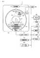
図1は、本実施形態に係るX線コンピュータ断層撮影装置1の構成を示している。本X線コンピュータ断層撮影装置1は、架台部100、投影データ発生部200、再構成部300、入力部400、表示部500、特定部600、代表値計算部700、スキャン開始タイミング決定部800、制御部900、記憶部1000を有する。なお、X線コンピュータ断層撮影装置1は、図示していないインターフェース(以下、I/Fと呼ぶ)を有していてもよい。I/Fは、本X線コンピュータ断層撮影装置1を電子的通信回線(以下、ネットワークと呼ぶ)と接続する。ネットワークには、図示していない放射線部門情報管理システムおよび図示していない病院情報システムなどが接続される。 FIG. 1 shows the configuration of an X-ray computed tomography apparatus 1 according to the present embodiment. The present X-ray computed tomography apparatus 1 includes a
架台部100には、図示していない回転支持機構が収容される。回転支持機構は、回転リング101と、回転軸Zを中心として回転自在に回転リング101を支持するリング支持機構と回転リング101の回転を駆動する回転駆動部(電動機)103とを有する。回転リング101には、X線発生部105と、図示していないコリメーターユニット、2次元アレイ型または多列型とも称されるエリア検出器(以下、X線検出部と呼ぶ)107、データ収集回路(Data Acquisition System:以下、DASと呼ぶ)109、非接触データ伝送部111、図示していない冷却装置及びガントリ制御装置などが搭載される。 The
X線発生部105は、高電圧発生部1051と、X線管1053とを有する。高電圧発生部1051は、後述する制御部900による制御の下で、スリップリング113を介して供給された電力を用いて、X線管1053に印加する管電圧と、X線管1053に供給する管電流とを発生する。 The
X線管1053は、高電圧発生部1051からの管電圧の印加および管電流の供給を受けて、X線の焦点からX線を放射する。高電圧発生部1051により供給される管電流が異なる場合、X線管1053は、複数の管電流にそれぞれ対応する複数のエネルギースペクトルを有するX線を発生する。以下、説明を簡単にするために、管電流は2種類であるとし、それぞれ本スキャン用管電流(以下、本スキャン管電流と呼ぶ)、プリスキャン用管電流(以下、プリスキャン管電流と呼ぶ)であるとする。プリスキャン管電流は、本スキャン管電流より小さい。これにより、プリスキャン管電流により発生されるX線の線量は、本スキャン管電流により発生される線量より低くなる。本スキャン及びプリスキャンについては、後の入力部400で詳述する。 The
X線の焦点から放射されたX線は、X線管1053のX線放射窓に取り付けられたコリメーターユニットにより、例えばコーンビーム形(角錐形)に整形される。X線の放射範囲は、点線115で示されている。X軸は、回転軸Zと直交し、放射されるX線の焦点を通る直線である。Y軸は、X軸および回転軸Zと直交する直線である。なお、説明の便宜上このXYZ座標系は、回転軸Zを中心として回転する回転座標系として説明する。 The X-ray emitted from the focal point of the X-ray is shaped into, for example, a cone beam shape (pyramid shape) by a collimator unit attached to the X-ray radiation window of the
X線検出部107は、回転軸Zを挟んでX線管1053に対向する位置およびアングルで、回転リング101に搭載される。X線検出部107は、複数のX線検出素子を有する。ここでは、単一のX線検出素子が単一のチャンネルを構成しているものとして説明する。複数のチャンネルは、回転軸Zに直交し、かつ放射されるX線の焦点を中心として、この中心から1チャンネル分のX線検出素子の受光部中心までの距離を半径とする円弧方向(チャンネル方向)とZ方向(スライス方向)との2方向に関して2次元状に配列される。 The
なお、X線検出部107は、複数のX線検出素子を1列に配列した複数のモジュールで構成されてもよい。このとき、モジュール各々は、上記チャンネル方向に沿って略円弧方向に1次元状に配列される。また、複数のX線検出素子は、チャンネル方向とスライス方向との2方向に関して2次元状に配列させてもよい。すなわち、2次元状の配列は、上記チャンネル方向に沿って一次元状に配列された複数のチャンネルを、スライス方向に関して複数列並べて構成される。このような2次元状のX線検出素子配列を有するX線検出部107は、略円弧方向に1次元状に配列される複数の上記モジュールをスライス方向に関して複数列並べて構成してもよい。 The
撮影又はスキャンに際しては、X線管1053とX線検出部107との間の円筒形の撮影領域117内に、被検体Pが天板119に載置されて挿入される。X線検出部107の出力側には、DAS109が接続される。 At the time of imaging or scanning, the subject P is placed on the
DAS109には、X線検出部107における複数のチャンネル各々の電流信号を電圧に変換するI−V変換器と、この電圧信号をX線の曝射周期に同期して周期的に積分する積分器と、この積分器の出力信号を増幅するアンプと、このアンプの出力信号をディジタル信号変換するアナログ・デジタル・コンバータとが、チャンネルごとに取り付けられている。DAS109から出力されるデータ(純生データ(pure raw data))は、磁気送受信又は光送受信を用いた非接触データ伝送部111を経由して、後述する投影データ発生部200に伝送される。 The
投影データ発生部200は、X線検出部107からの出力に基づいて、X線検出部107における複数のチャンネルにそれぞれ対応する複数の投影データ値を発生する。具体的には、投影データ発生部200は、DAS109から出力される純生データに対して前処理を施す。前処理には、例えばチャンネル間の感度不均一補正処理、X線強吸収体、主に金属部による極端な信号強度の低下または、信号脱落を補正する処理等が含まれる。投影データ発生部200から出力される再構成処理直前のデータ(生データ(raw data)または、投影データと称される、ここでは投影データという)は、データ収集したときにビュー角、チャンネルナンバーなどを表すデータと関連付けられて、後述する代表値計算部700に出力される。なお、投影データは、磁気ディスク、光磁気ディスク、又は半導体メモリを備えた記憶部1000に記憶されてもよい。 The projection
なお、投影データとは、被検体を透過したX線の強度に応じたデータ値(以下、投影データ値と呼ぶ)の集合である。ここでは説明の便宜上、ワンショットで略同時に収集したビュー角が同一である全チャンネルにわたる一揃いの投影データ値を、投影データセットと称する。また、ビュー角は、X線管1053が回転軸Zを中心として周回する円軌道の各位置を、回転軸Zから鉛直上向きにおける円軌道の最上部を0°として360°の範囲の角度で表したものである。なお、投影データセットの各チャンネルに対する投影データ値は、ビュー角、コーン角、チャンネル番号によって識別される。 The projection data is a set of data values (hereinafter referred to as projection data values) according to the intensity of X-rays transmitted through the object. Here, for convenience of explanation, a set of projection data values across all channels having the same view angle acquired substantially simultaneously in one shot is referred to as a projection data set. In addition, the view angles are shown at an angle of 360 ° with each position of the circular orbit around which the
再構成部300は、ビュー角が360°又は180°+ファン角の範囲内の投影データセットに基づいて、フェルドカンプ法またはコーンビーム再構成法により、略円柱形の3次元画像を再構成する機能を有する。再構成部300は、例えばファンビーム再構成法(ファンビーム・コンボリューション・バックプロジェクション法ともいう)またはフィルタード・バックプロジェクション法により2次元画像(断層画像)を再構成する機能を有する。フェルドカンプ法は、コーンビームのように再構成面に対して投影レイが交差する場合の再構成法であり、コーン角が小さいことを前提として畳み込みの際にはファン投影ビームとみなして処理し、逆投影はスキャンの際のレイに沿って処理する近似的画像再構成法である。コーンビーム再構成法は、フェルドカンプ法よりもコーン角のエラーが抑えられる方法として、再構成面に対するレイの角度に応じて投影データを補正する再構成法である。再構成部300は、投影データセットに基づいて、被検体Pに関する断面画像を再構成する。再構成された画像(断面画像、3次元画像など)は、記憶部1000に記憶される。 The
入力部400は、操作者からの各種指示・命令・情報・選択・設定を本X線コンピュータ断層撮影装置1に取り込む。取り込まれた各種指示・命令・情報・選択・設定は、後述する制御部900などに出力される。入力部(設定部)400は、図示しないが、関心領域(Region Of Interest:以下、ROIと呼ぶ)の設定などを行うためのトラックボール、スイッチボタン、マウス、キーボード等を有する。 The
入力部400は、被検体に対するスキャンの開始位置および撮影条件等を決めるための撮影(以下、スキャノ(scano)撮影と呼ぶ)により発生され、表示されたスキャノ像に対して、後述する関心領域設定スキャン(以下、ROI設定スキャン(第1スキャン)と呼ぶ)のスキャン位置を入力する。なお、入力部400は、プリスキャン(第2スキャン)および本スキャン(第3スキャン)のスキャン位置を入力してもよい。また、入力部400は、スキャン開始タイミング決定部800で用いられる閾値を入力することも可能である。入力される閾値は、例えば、プリスキャンにおいて、代表値計算部700で計算される比の上昇率(%)であってもよい。 The
ROI設定スキャンとは、造影剤の検出に関する血管またはROIを設定するために再構成された断面画像(以下、ROI設定画像と呼ぶ)を再構成するためのスキャンである。プリスキャンとは、ROI設定スキャン後でかつ本スキャンの前であって、造影剤が注入された被検体に対して実行されるスキャンである。プリスキャンは、ROI設定スキャンおよび本スキャンにおける線量より低い線量のX線を発生する。以下、説明を簡単にするために、プリスキャンは、0°のビュー角から実行されるものとする。 The ROI setting scan is a scan for reconstructing a cross-sectional image (hereinafter referred to as an ROI setting image) reconstructed to set a blood vessel or an ROI for detection of a contrast agent. The pre-scan is a scan that is performed on a subject injected with a contrast agent after the ROI setting scan and before the main scan. The prescan generates a lower dose of X-rays than the dose in the ROI setting scan and the main scan. In the following, for the sake of simplicity, it is assumed that prescan is performed from a view angle of 0 °.
本スキャンとは、スキャン開始タイミング決定部800により決定されたタイミングに従って、被検体に対して実行されるスキャンである。以下、説明を簡単にするために、ROI設定スキャン、プリスキャン、本スキャンは、同じスキャン位置で実行されるものとする。なお、本スキャンにおけるスキャン位置は、ROI設定スキャンにおけるスキャン位置およびプリスキャンにおけるスキャン位置と異なっていてもよい。 The main scan is a scan performed on the subject according to the timing determined by the scan start timing
入力部(設定部)400は、ROI設定スキャンにより再構成されたROI設定画像、すなわち被検体の断面画像に対して、操作者の指示に従ってROIを入力(設定)する。入力されたROIは、後述する特定部600に出力される。図2は、表示部500に表示されたROI設定画像と、ROI設定画像に設定されたROIとの一例を示す図である。 The input unit (setting unit) 400 inputs (sets) an ROI in accordance with an instruction from the operator on an ROI setting image reconstructed by the ROI setting scan, that is, a cross-sectional image of the subject. The input ROI is output to the identifying
入力部400は、表示画面上に表示されるカーソルの座標を検出し、検出した座標を制御部900に出力する。なお、入力部400は、表示画面を覆うように設けられたタッチパネルでもよい。この場合、入力部400は、電磁誘導式、電磁歪式、感圧式等の座標読み取り原理でタッチ指示された座標を検出し、検出した座標を制御部900に出力する。 The
表示部500は、ROI設定画像、本スキャンにより再構成された再構成画像(以下、本スキャン画像と呼ぶ)を表示する。表示部500は、X線コンピュータ断層撮影のために設定される条件などを表示する。表示部500は、ROI設定画像上に、後述する入力部400を介して入力されたROIを表示する。 The
なお、表示部500は、プリスキャンにおいて収集された投影データ値に基づいて再構成された再構成画像(以下、プリスキャン画像と呼ぶ)を表示してもよい。このとき、表示部500は、例えば、プリスキャン開始前または被検体への造影剤の注入前においてROI設定画像を表示する。次いで、表示部500は、プリスキャン開始後または被検体への造影剤の注入後においてプリスキャン画像を、ROI設定画像に替えて表示してもよい。なお、上記プリスキャン画像とROI設定画像とは、同一断面であってもよい。 The
特定部600は、ROI設定画像上に設定されたROIに基づいて、ROIに対応する被検体内の部分領域を透過した複数のX線のレイ(以下、部分レイと呼ぶ)にそれぞれ対応する複数のチャンネル(以下、チャンネル群と呼ぶ)を、複数のビュー(具体的には、ビュー角)各々に対して特定する。チャンネル群における複数のチャンネルは、ビュー角ごとに部分領域を透過した複数の部分レイがそれぞれ到達した複数のチャンネルに対応する。 A plurality of
図3は、あるビュー角において、ROIに対応する被検体内の部分領域を透過する複数の部分レイを含む範囲を、特定された複数のチャンネル(チャンネル群)を含む範囲(以下、特定チャンネル範囲と呼ぶ)とともに示す図である。図3に示すように、特定部600は、ROIとビュー角とに基づいて、特定チャンネル範囲に含まれる複数のチャンネル(チャンネル群)を特定する。 FIG. 3 shows a range including a plurality of partial rays transmitting a partial region in the subject corresponding to the ROI at a certain view angle, a range including a plurality of specified channels (channel groups) (hereinafter referred to as a specific channel range ) And is shown. As shown in FIG. 3, the identifying
以下、説明を簡単にするために、回転軸周りにX線管1053が1回転する間に収集されるビュー数は、1200であるとする。このとき、複数のビューにおいて隣接するビューの間の角度は、360°/1200=0.3°となる。 Hereinafter, in order to simplify the description, it is assumed that the number of views collected during one rotation of the
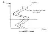
図4は、ビュー数とチャンネル番号とにより規定される投影データ値を斜線で表したサイノグラムにおいて、1200ビューに亘る特定チャンネル範囲の分布(以下、サイノグラムROIと呼ぶ)の一例を示す図である。図4は、サイノグラムROI上においてビューiに対応する特定チャンネル範囲を示している。 FIG. 4 is a diagram showing an example of distribution of a specific channel range (hereinafter called sinogram ROI) across 1200 views in a sinogram in which projection data values defined by the number of views and channel numbers are indicated by oblique lines. FIG. 4 shows a specific channel range corresponding to view i on sinogram ROI.
なお、特定部600は、ROI設定画像に設定されたROIとビュー角とに基づいて、サイノグラムROIに含まれる複数の特定チャンネル範囲を、サイノグラムに対して特定してもよい。特定部600は、複数のビュー各々における特定チャンネル範囲に含まれる複数のチャンネル番号を、代表値計算部700に出力する。 The identifying
代表値計算部700は、プリスキャンに関する投影データ値のうち、プリスキャンにおけるビューごとの特定チャンネル範囲に関する複数の投影データ値(関心投影データ値)に基づいて、プリスキャンにおけるビュー各々に関する基準値を計算する。関心投影データ値は、ビュー各々において、特定されたチャンネル(チャンネル範囲)に対応する。次いで、代表値計算部700は、基準値に関する関心投影データ値の発生後の第2スキャンにおいて発生された関心投影データ値と基準値とに基づいて代表値をビューごとに計算する。代表値とは、特定チャンネル範囲における複数の関心投影データ値を代表する値である。 The representative
代表値計算部700は、プリスキャンにおいてX線発生部105(または回転リング101)の所定の回転数に関するビュー各々における関心投影データ値の平均を、基準値として計算する。なお、代表値計算部700は、プリスキャンにおけるX線発生部105の回転回数の更新に応じて、回転回数の更新前のビュー各々における関心投影データ値の平均を、基準値として計算してもよい。代表値計算部700は、基準値に対する関心投影データ値の平均値の比を、代表値として計算する。なお、代表値計算部700は、基準値と関心投影データ値の平均値との差を、代表値として計算してもよい。以下、基準値および代表値の計算について詳述する。 The representative
代表値計算部700は、プリスキャンの実行中において、特定チャンネル範囲に含まれる複数のチャンネルにそれぞれ対応する複数の投影データ値に基づいて、代表値を計算する。具体的には、代表値計算部700は、プリスキャンにおけるビューごとの特定チャンネル範囲に関する複数の投影データ値(関心投影データ値)の平均値を計算する。すなわち、代表値計算部700は、複数のビューにそれぞれ対応する複数の平均値を、ビュー各々の特定チャンネル範囲に含まれる複数のチャンネルにそれぞれ対応する複数の投影データ値を用いて計算する。代表値計算部700は、プリスキャンにおいて、回転リング101の1回転目における複数のビューにそれぞれ対応する複数の平均値(以下、基準平均値(基準値)と呼ぶ)を、記憶部1000に記憶させる。 The representative
プリスキャンにおける回転リング101の2回転目以降において、例えば、0°のビュー角で投影データ値が収集されると、代表値計算部700は、特定チャンネル範囲における複数の投影データ値の平均値を計算する。また、代表値計算部700は、0°のビュー角に対応する基準平均値を、記憶部1000から読み出す。代表値計算部700は、読み出した基準平均値に対する計算された平均値の比を計算する。代表値計算部700は、計算した比を、代表値として、スキャン開始タイミング決定部800へ出力する。 For example, when projection data values are collected at a view angle of 0 ° after the second rotation of the
次いで、0°のビュー角におけるビューの次のビュー(0.3°のビュー角)に関する投影データ値が収集されると、代表値計算部700は、特定チャンネル範囲における複数の投影データ値の平均値を計算する。また、代表値計算部700は、0.3°のビュー角に対応する基準平均値を、記憶部1000から読み出す。代表値計算部700は、読み出した基準平均値に対する計算された平均値の比を計算する。代表値計算部700は、計算した比を、代表値としてスキャン開始タイミング決定部800へ出力する。 Then, when projection data values for the next view of the view at a view angle of 0 ° (view angle of 0.3 °) are collected, the representative
代表値計算部700は、ビューごとに投影データ値が収集されると、上記処理を繰り返す。代表値計算部700は、プリスキャンの終了に同期して、上記処理を停止する。なお、代表値計算部700は、DAS109から出力された純生データに対して、代表値を同様にして計算してもよい。 The representative
なお、代表値計算部700は、基準平均値と計算された平均値との差分値を、ビューごとの代表値として、計算してもよい。差分値は、計算された平均値から基準平均値を差分した値であってもよいし、基準平均値から計算された平均値を差分した値であってもよい。また、代表値計算部700は、ビューごとの代表値として、差分値に絶対値を計算してもよい。 The representative
なお、基準値は、上述したように、プリスキャンの回転回数に応じて逐次更新されてもよい。例えば、代表値計算部700は、プリスキャンにおいてX線発生部105を搭載した回転リング101の回転回数の更新に応じて、回転回数の更新前の複数のビュー各々における関心投影データ値の平均を基準値として計算する。次いで、代表値計算部700は、基準値に関する関心投影データ値の発生後のプリスキャンにおいて発生された前記関心投影データ値と基準値とに基づいて、関心投影データ値を代表する代表値を、関心投影データ値の発生に応じて、ビューごとに計算する。 The reference value may be sequentially updated according to the number of rotations of the pre-scan, as described above. For example, the representative
スキャン開始タイミング決定部800は、ROI設定スキャンより低線量のプリスキャンにおいて発生された投影データ値のうち関心領域に対応する複数の関心投影データ値に基づいて、プリスキャンを終了し、プリスキャンより高線量の本スキャンを開始するタイミングを決定する。例えば、スキャン開始タイミング決定部800は、所定のビュー数に亘って、代表値が所定の閾値を超え続けたことに応答して、本スキャンを開始するタイミングを決定する。以下、本スキャンを開始するタイミングの決定について詳述する。 The scan start timing
スキャン開始タイミング決定部800は、所定の閾値、所定のビュー数を記憶する。なお、所定の閾値と所定のビュー数とは、後述する記憶部1000に記憶されてもよい。スキャン開始タイミング決定部800は、代表値計算部700から出力された代表値を所定の閾値と比較する。スキャン開始タイミング決定部800は、ビューごとに計算された代表値が所定のビュー数に亘って超過した時点を、本スキャン開始のタイミングとして決定する。スキャン開始タイミング決定部800は、決定した本スキャン開始のタイミングを、後述する制御部900に出力する。なお、スキャン開始タイミング決定部800は、ビュー数の代わりにビュー角を用いて、本スキャン開始のタイミングを決定してもよい。このとき、スキャン開始タイミング決定部800は、所定のビュー数の代わりに所定のビュー角を記憶する。 The scan start timing
具体的には、スキャン開始タイミング決定部800は、所定の閾値を超えた代表値に対応するビュー数を記憶する。スキャン開始タイミング決定部800は、記憶したビュー数に所定のビュー数を加算した加算ビュー数を計算する。スキャン開始タイミング決定部800は、ビューごとに計算された代表値が、記憶したビュー数から加算ビュー数まで連続して所定の閾値を超過したか否かを判定する。すなわち、スキャン開始タイミング決定部800は、加算ビュー数まで代表値が所定の閾値を超え続けた場合、加算ビュー数に対応した時点を、本スキャン開始のタイミングとして決定する。所定のビュー数とは、例えば、100ビューである。 Specifically, the scan start timing
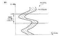
図5は、ある回転数におけるサイノグラムデータにおいて、スキャン開始のタイミングを説明するための説明図である。図5に示すように、あるビュー数iで、代表値が所定の閾値を超えたとする。所定のビュー数が例えば100である場合、スキャン開始タイミング決定部800は、(i+100)ビューまで連続して代表値が所定の閾値を超過した時点を、本スキャン開始のタイミングとして決定する。 FIG. 5 is an explanatory diagram for explaining the timing for starting scanning in sinogram data at a certain rotation number. As shown in FIG. 5, it is assumed that the representative value exceeds a predetermined threshold with a certain view number i. When the predetermined number of views is, for example, 100, the scan start timing
プリスキャンにおいて、基準値が回転リング101の回転回数に応じて逐次更新される場合、スキャン開始タイミング決定部800は、関心投影データ値を代表する代表値が所定の閾値を超えた後、所定のビュー数に亘って、代表値が所定の符号(例えば、プラス)を維持し続けたことに応答して、本スキャン開始のタイミングを決定する。 In the pre-scan, when the reference value is sequentially updated according to the number of rotations of the
制御部900は、本X線コンピュータ断層撮影装置1の中枢として機能する。制御部900は、図示しないCPUとメモリとを備える。制御部900は、図示していないメモリに記憶された検査スケジュールデータと制御プログラムとに基づいて、X線コンピュータ断層撮影のために高電圧発生部1051、および架台部100などを制御する。具体的には、制御部900は、入力部400および図示していない放射線部門情報管理システムおよび図示していない病院情報システムなどから送られてくる操作者の指示などを、一時的に図示していないメモリに記憶する。制御部900は、メモリに一時的に記憶されたこれらの情報に基づいて、高電圧発生部1051、および架台部100などを制御する。制御部900は、所定の画像発生・表示等を実行するための制御プログラムを、記憶部1000から読み出して自身が有するメモリ上に展開し、各種処理に関する演算・処理等を実行する。 The control unit 900 functions as a center of the present X-ray computed tomography apparatus 1. The control unit 900 includes a CPU and a memory (not shown). The control unit 900 controls the high
制御部900は、スキャノ(scano)撮影を、被検体に対して実行するために、高電圧発生部1051、投影データ発生部200、再構成部300などを制御する。制御部900は、スキャノ撮影により発生された被検体に対するスキャノ像を表示させるために、表示部500を制御する。制御部900は、ROI設定スキャンを実行するために、高電圧発生部1051、投影データ発生部200、再構成部300を制御する。ROI設定スキャンにおける管電流は、本スキャン管電流と同様である。制御部900は、ROI設定スキャンにより発生された複数の投影データ値に基づいて、ROI設定画像を再構成させるために再構成部300を制御する。制御部900は、再構成されたROI設定画像を表示部500に表示させるために、表示部500を制御する。 The control unit 900 controls the high
制御部900は、プリスキャンを実行するために、高電圧発生部1051、投影データ発生部200、再構成部300などを制御する。具体的には、制御部900は、プリスキャンにおいて、ROI設定スキャン及び本スキャンに比べて低い線量に対応するX線を発生させるために、高電圧発生部1051を制御する。プリスキャンにおいて高電圧発生部1051から供給される管電流は、ROI設定スキャンおよび本スキャンにおいて高電圧発生部1051から供給される管電流より小さい。制御部900は、プリスキャンによる投影データ値の収集に応じて代表値を計算させるために、代表値計算部700を制御する。制御部900は、代表値の計算に応じて、本スキャン開始のタイミングを決定させるために、スキャン開始タイミング決定部800を制御する。 The control unit 900 controls the high
制御部900は、プリスキャンにより発生された複数の投影データ値に基づいて、ROI設定画像と同一断面のプリスキャン画像を再構成させるために再構成部300を制御する。制御部900は、プリスキャン画像を表示部500に表示させるために、表示部500を制御する。制御部900は、表示部500に表示されたROI設定画像を、プリスキャン画像に替えて表示させるために、表示部500を制御する。 The control unit 900 controls the
スキャン開始タイミング決定部800から本スキャン開始のタイミングが入力されると、制御部900は、プリスキャンを停止させるために、X線管1053、高電圧発生部1051、回転駆動部103などを制御する。また、制御部900は、本スキャン開始のタイミングの入力契機として、本スキャンを実行するために、高電圧発生部1051、X線管1053、回転駆動部103などを制御する。制御部900は、本スキャンにより収集された複数の投影データ値に基づいて、本スキャン画像を再構成させるために、再構成部300を制御する。制御部900は、本スキャン画像を表示部500に表示させるために、表示部を制御する。 When the main scan start timing is input from the scan start timing
記憶部1000は、本X線コンピュータ断層撮影装置1の各種制御に関するプログラムを記憶する。なお、記憶部1000は、本スキャン開始のタイミングを決定するプログラムを記憶してもよい。また、記憶部1000は、本スキャン管電流、プリスキャン管電流に関する値を記憶する。記憶部1000は、投影データ発生部200により発生された複数の投影データ値を記憶する。記憶部1000は、スキャノ像、プリスキャンにおけるサイノグラム、ROI設定画像、プリスキャン画像、本スキャン画像、基準平均値などを記憶する。なお、記憶部1000は、所定の閾値、所定のビュー数などを記憶してもよい。 The
(スキャン開始タイミング決定機能)
スキャン開始タイミング決定機能とは、プリスキャンにおいて、ビューごとに計算された代表値と所定の閾値と所定のビュー数とに基づいて、本スキャン開始のタイミングを決定する機能である。以下、スキャン開始タイミング決定機能に従う処理(以下、スキャン開始タイミング決定処理と呼ぶ)を説明する。(Scan start timing determination function)
The scan start timing determination function is a function to determine the main scan start timing based on the representative value calculated for each view, a predetermined threshold, and a predetermined number of views in the pre-scan. Hereinafter, processing according to the scan start timing determination function (hereinafter, referred to as scan start timing determination processing) will be described.
図6は、スキャン開始タイミング決定処理の手順の一例を示すフローチャートである。
被検体に対してスキャノ撮影が実行される。スキャノ撮影により発生されたスキャノ像に基づいて、ROI設定スキャンおよび本スキャンの開始位置、撮影条件等が、入力部400を介して入力される。入力された位置において、ROI設定スキャンが実行される。ROI設定スキャンにより発生された複数の投影データ値に基づいて、ROI設定画像が再構成される(ステップSa1)。ROI設定画像に対して、ROIが設定される(ステップSa2)。設定されたROIに基づいて、部分領域を透過した部分レイに対応するチャンネル群が、複数のビュー各々に対して特定される(ステップSa3)。被検体への造影剤注入を契機として、プリスキャンが開始される(ステップSa4)。FIG. 6 is a flowchart showing an example of the procedure of scan start timing determination processing.
Scanography is performed on the subject. Based on the scanogram generated by scanography, the ROI setting scan, the start position of the main scan, the imaging condition, and the like are input through the
X線検出部107からの出力に基づいて、複数の投影データ値が発生される(ステップSa5)。特定されたチャンネル群に関する複数の投影データ値の平均(平均値)が計算される(ステップSa6)。回転リング101の回転数が1未満であれば(ステップSa7)、計算された平均値は、基準平均値として、記憶部1000に記憶される(ステップSa8)。回転リング101の回転数が1以上であれば(ステップSa7)、基準平均値に対する計算された平均値の比(代表値)が計算される(ステップSa9)。計算された代表値が所定の閾値以下であれば(ステップSa10)、ステップSa5、ステップSa6、ステップSa9が繰り返される。 A plurality of projection data values are generated based on the output from the X-ray detection unit 107 (step Sa5). An average (average value) of a plurality of projection data values regarding the identified channel group is calculated (step Sa6). If the rotation speed of the
計算された代表値が所定の閾値を超えていれば(ステップSa10)、以下のステップSa11の処理が実行される。すなわち、所定のビュー数に亘って代表値が連続して所定の閾値を超過していなければ(ステップSa11)、ステップSa5、ステップSa6、ステップSa9が繰り返される。所定のビュー数に亘って代表値が連続して所定の閾値を超過していれば(ステップSa11)、本スキャン開始のタイミングが決定され、本スキャンが実行される(ステップSa12)。 If the calculated representative value exceeds the predetermined threshold (step Sa10), the process of step Sa11 below is performed. That is, if the representative value does not continuously exceed the predetermined threshold over the predetermined number of views (step Sa11), steps Sa5, Sa6, and Sa9 are repeated. If the representative value continuously exceeds the predetermined threshold value over the predetermined number of views (step Sa11), the timing of the main scan start is determined, and the main scan is performed (step Sa12).
なお、プリスキャンにおいて、基準値が回転リング101の回転回数に応じて逐次更新される場合、ステップSa9は、一つ前の回転数における同一ビューにおける平均値を基準平均値として、代表値を計算する処理となる。また、ステップSa11は、代表値が所定の閾値を超えた後、所定のビュー数に亘って、代表値が所定の符号を維持し続けたか否かを判定する処理となる。 When the reference value is successively updated according to the number of rotations of the
(変形例)
本実施形態との相違は、基準平均値として、ROI設定スキャンにより発生された投影データ値を用いることにある。本変形例におけるX線コンピュータ断層撮影装置の構成要素は、図1に示す本実施形態と同様である。以下、本実施形態と異なる機能を有する構成要素について説明する。(Modification)
The difference from the present embodiment is that the projection data values generated by the ROI setting scan are used as the reference average value. The components of the X-ray computed tomography apparatus in the present modification are the same as those of the present embodiment shown in FIG. Hereinafter, components having functions different from those of the present embodiment will be described.
代表値計算部700は、ROI設定スキャンにおける複数のビュー各々において、特定されたチャンネル群に関する複数の投影データ値の平均を、基準平均値として計算する。代表値計算部700は、基準平均値をスキャン開始タイミング決定部800に出力する。 The representative
(スキャン開始タイミング決定機能)
本変形例に係るスキャン開始タイミング決定機能は、基準平均値としてROI設定スキャンにより発生された投影データ値を用いて基準平均値を計算し、ビューごとに計算された代表値と所定の閾値と所定のビュー数とに基づいて、本スキャン開始のタイミングを決定する機能である。(Scan start timing determination function)
The scan start timing determination function according to this modification calculates a reference average value using projection data values generated by the ROI setting scan as a reference average value, and calculates a representative value calculated for each view, a predetermined threshold, and a predetermined value. It is a function to determine the timing of the start of the main scan based on the number of views.
図7は、本変形例に係るスキャン開始タイミング決定処理の手順の一例を示すフローチャートである。
ROI設定スキャンにより発生された複数の投影データ値に基づいて、ROI設定画像が再構成される。ROI設定画像に対して、ROIが設定される。設定されたROIに基づいて、部分領域を透過した部分レイに対応するチャンネル群が、複数のビュー各々に対して特定される。ROI設定スキャンにおいて、特定チャンネル群に関する複数の投影データ値の平均(基準平均値)が計算される(ステップSb1)。FIG. 7 is a flowchart illustrating an example of the procedure of scan start timing determination processing according to the present modification.
An ROI setting image is reconstructed based on the plurality of projection data values generated by the ROI setting scan. An ROI is set for the ROI setting image. Based on the set ROI, a group of channels corresponding to the partial ray transmitted through the partial region is identified for each of the plurality of views. In the ROI setting scan, an average (reference average value) of a plurality of projection data values regarding a specific channel group is calculated (step Sb1).
被検体への造影剤注入を契機として、プリスキャンが開始される(ステップSb2)。X線検出部107からの出力に基づいて、複数の投影データ値が発生される(ステップSb3)。特定されたチャンネル群に関する複数の投影データ値の平均(平均値)が計算される(ステップSb4)。基準平均値に対する計算された平均値の比(代表値)が計算される(ステップSb5)。計算された代表値が所定の閾値以下であれば(ステップSb6)、ステップSb3乃至ステップSb5が繰り返される。 Prescan is started in response to the injection of the contrast agent into the subject (step Sb2). A plurality of projection data values are generated based on the output from the X-ray detection unit 107 (step Sb3). An average (average value) of a plurality of projection data values regarding the identified channel group is calculated (step Sb4). A ratio (representative value) of the calculated average value to the reference average value is calculated (step Sb5). If the calculated representative value is less than or equal to the predetermined threshold (step Sb6), steps Sb3 to Sb5 are repeated.
計算された代表値が所定の閾値を超えていれば(ステップSb6)、以下のステップSb7の処理が実行される。すなわち、所定のビュー数に亘って代表値が連続して所定の閾値を超過していなければ(ステップSb7)、ステップSb3乃至ステップSb6が繰り返される。所定のビュー数に亘って代表値が連続して所定の閾値を超過していれば(ステップSb7)、本スキャン開始のタイミングが決定され、本スキャンが実行される(ステップSb8)。 If the calculated representative value exceeds the predetermined threshold (step Sb6), the process of step Sb7 below is performed. That is, if the representative value does not continuously exceed the predetermined threshold over the predetermined number of views (step Sb7), steps Sb3 to Sb6 are repeated. If the representative value continuously exceeds the predetermined threshold value over the predetermined number of views (step Sb7), the timing of the main scan start is determined, and the main scan is executed (step Sb8).
なお、プリスキャンにおいて、基準値が回転リング101の回転回数に応じて逐次更新される場合、ステップSb5における基準値は、プリスキャンの回転数が1の場合、ROI設定スキャンにより計算された同一ビューの基準平均値となる。一方、プリスキャンの回転数が2以上の場合、ステップSb5における基準値は、プリスキャンにおける一つ前の回転数における同一ビューにおける平均値を基準平均値として、代表値を計算する処理となる。また、ステップSb7は、代表値が所定の閾値を超えた後、所定のビュー数に亘って、代表値が所定の符号を維持し続けたか否かを判定する処理となる。 When the reference value is sequentially updated according to the number of rotations of the
以上に述べた構成によれば、以下の効果を得ることができる。
本実施形態におけるX線コンピュータ断層撮影装置1によれば、ROIへの造影剤の到達の有無を判定するプリスキャンにおいて、ビューごとに計算された代表値と所定の閾値と所定のビュー数とに基づいて、本スキャン開始のタイミングを決定することができる。具体的には、本実施形態によれば、予め設定されたROIに対応するチャンネル群を、ビューごとに特定することができる。すなわち、本実施形態によれば、サイノグラム上に、ROIに対応する領域(サイノグラムROI)を特定することができる。次いで、本実施形態によれば、特定チャンネル群に関する複数の投影データ値に基づいて、ビューごとに計算された代表値と、所定の閾値と、所定のビュー数とに基づいて、本スキャン開始のタイミングを決定することができる。また、本実施形態の変形例によれば、プリスキャン前のROI設定スキャンにおける複数の投影データ値と特定されたチャンネル群とに基づいて、代表値の計算に用いられる基準平均値を計算することができる。According to the configuration described above, the following effects can be obtained.
According to the X-ray computed tomography apparatus 1 in the present embodiment, the representative value calculated for each view, the predetermined threshold value, and the predetermined number of views in the prescan for determining the presence or absence of the contrast agent reaching the ROI. Based on the timing of the main scan start can be determined. Specifically, according to the present embodiment, a channel group corresponding to a preset ROI can be identified for each view. That is, according to the present embodiment, a region (sinogram ROI) corresponding to the ROI can be identified on the sinogram. Next, according to the present embodiment, the main scan is started based on the representative value calculated for each view, the predetermined threshold, and the predetermined number of views based on the plurality of projection data values regarding the specific channel group. The timing can be determined. Further, according to the modification of the present embodiment, the reference average value used for calculation of the representative value is calculated based on the plurality of projection data values in the ROI setting scan before the prescan and the specified channel group. Can.
これらのことから、本実施形態に係る本X線コンピュータ断層撮影装置1によれば、ビューごとに収集された投影データ値に基づいて、ROI内への造影剤の流入を判定することができる。これにより、X線管1053を被検体周りに1回転させて投影データを収集する収集時間と、収集された投影データに基づいて画像を再構成する再構成時間とが不要となるため、造影剤注入モニタリングの精度が向上する。また、ROI内への造影剤の流入の判定において、ノイズおよびアーチファクトの影響を無効にすることができる。 From the above, according to the present X-ray computed tomography apparatus 1 according to the present embodiment, the inflow of the contrast agent into the ROI can be determined based on the projection data values collected for each view. As a result, it is not necessary to collect the projection data by rotating the
すなわち、本実施形態に係るX線コンピュータ断層撮影装置1によれば、基準値を用いて規格化(比または差分)した代表値を本スキャン開始のタイミングの判定対象として用いることにより、設定された関心領域周辺の臓器による関心投影データ値への影響を低減させることができる。加えて、所定のビュー数に亘って代表値が所定の閾値を超え続けたことに応答して本スキャンを開始することは、ROI外の血管への造影剤の流入による代表値への影響を、除外することができる。 That is, according to the X-ray computed tomography apparatus 1 according to the present embodiment, the representative value normalized (ratio or difference) using the reference value is set by using it as the determination target of the main scan start timing. The influence on the projection data value of interest by the organ around the region of interest can be reduced. In addition, starting the main scan in response to the representative value continuing to exceed the predetermined threshold for the predetermined number of views has an effect on the representative value due to the inflow of the contrast agent into the blood vessel outside the ROI. , Can be excluded.
図8は、プリスキャン中におけるスキャン開始タイミング決定処理において、代表値の時間変化を、所定の閾値及び所定のビュー数とともに示している。図8に示すように、ROI外における造影血管の影響により、代表値が所定の閾値を超えた状態の持続期間は、所定のビュー数より少ない。このため、本実施形態に係るX線コンピュータ断層撮影装置1によれば、ROI外における造影血管の影響を、スキャン開始タイミング決定処理において、除外することが可能となる。これにより、本実施形態に係るX線コンピュータ断層撮影装置1によれば、図8に示すように、代表値が所定の閾値を超え続ける期間が所定のビュー数に達したとき、本スキャンを開始することができる。 FIG. 8 shows temporal change of the representative value together with a predetermined threshold value and a predetermined number of views in the scan start timing determination process during prescanning. As shown in FIG. 8, the duration of the state in which the representative value exceeds the predetermined threshold is less than the predetermined number of views due to the influence of the contrasted blood vessel outside the ROI. Therefore, according to the X-ray computed tomography apparatus 1 according to the present embodiment, the influence of the contrasted blood vessel outside the ROI can be excluded in the scan start timing determination process. Thereby, according to the X-ray computed tomography apparatus 1 according to the present embodiment, as shown in FIG. 8, the main scan is started when the period in which the representative value continues to exceed the predetermined threshold reaches the predetermined number of views. can do.
以上のことから、本実施形態に係る本X線コンピュータ断層撮影装置1によれば、造影剤注入モニタリング機構において、ROIへの造影剤のり流入の判定の精度を向上させることができる。また、被検体への被曝線量を低減させることができる。 From the above, according to the present X-ray computed tomography apparatus 1 according to the present embodiment, it is possible to improve the accuracy of the determination of the inflow of the contrast agent into the ROI in the contrast agent injection monitoring mechanism. In addition, the exposure dose to the subject can be reduced.
加えて、実施形態に係る各機能は、当該処理を実行する医用画像処理プログラムをワークステーション等のコンピュータにインストールし、これらをメモリ上で展開することによっても実現することができる。このとき、コンピュータに当該手法を実行させることのできるプログラムは、磁気ディスク(フロッピー(登録商標)ディスク、ハードディスクなど)、光ディスク(CD−ROM、DVDなど)、半導体メモリなどの記憶媒体に格納して頒布することも可能である。 In addition, each function according to the embodiment can also be realized by installing a medical image processing program for executing the processing in a computer such as a workstation and expanding the program on a memory. At this time, the program that can cause the computer to execute the method is stored in a storage medium such as a magnetic disk (floppy (registered trademark) disk, hard disk, etc.), optical disk (CD-ROM, DVD, etc.), semiconductor memory, etc. It is also possible to distribute it.
なお、本発明は上記実施形態そのままに限定されるものではなく、実施段階ではその要旨を逸脱しない範囲で構成要素を変形して具体化できる。また、上記実施形態に開示されている複数の構成要素の適宜な組み合わせにより、種々の発明を形成できる。例えば、実施形態に示される全構成要素から幾つかの構成要素を削除してもよい。さらに、異なる実施形態にわたる構成要素を適宜組み合わせてもよい。 The present invention is not limited to the above embodiment as it is, and at the implementation stage, the constituent elements can be modified and embodied without departing from the scope of the invention. In addition, various inventions can be formed by appropriate combinations of a plurality of constituent elements disclosed in the above embodiment. For example, some components may be deleted from all the components shown in the embodiment. Furthermore, components in different embodiments may be combined as appropriate.
1…X線コンピュータ断層撮影装置、100…架台部、101…回転リング、103…回転駆動部、105…X線発生部、107…X線検出部、109…データ収集回路(DAS)、111…非接触データ伝送部、113…スリップリング、115…X線の放射範囲、117…撮影領域、119…天板、200…投影データ発生部、300…再構成部、400…入力部(設定部)、500…表示部、600…特定部、700…代表値計算部、800…スキャン開始タイミング決定部、900…制御部、1000…記憶部、1051…高電圧発生部、1053…X線管。 DESCRIPTION OF SYMBOLS 1 X-ray computed
Claims (7)
Translated fromJapanese前記X線発生部から発生され、被検体を透過したX線を検出するX線検出部と、
前記X線検出部からの出力に基づいて、前記X線検出部における複数のチャンネルにそれぞれ対応する複数の投影データ値を発生する投影データ発生部と、
前記被検体に対する第1スキャンにより発生された断面画像上に関心領域を設定する設定部と、
前記第1スキャンより低線量の第2スキャンにおいて発生された前記投影データ値のうち前記関心領域に対応する複数の関心投影データ値を用いて、前記関心投影データ値の発生後の前記第2スキャンにおいて発生された前記関心投影データ値を規格化した値を、複数のビュー各々について計算する計算部と、
前記規格化した値が所定の閾値を所定のビュー数に亘って超え続けたことに応答して、前記第2スキャンを終了して前記第2スキャンより高線量の第3スキャンを開始するタイミングを決定するスキャン開始タイミング決定部と、
を具備するX線コンピュータ断層撮影装置。An X-ray generator that generates X-rays;
An X-ray detection unit for detecting X-rays generated from the X-ray generation unit and transmitted through the subject;
A projection data generation unit that generates a plurality of projection data values respectively corresponding to a plurality of channels in the X-ray detection unit based on an output from the X-ray detection unit;
A setting unit configured to set a region of interest on the cross-sectional image generated by the first scan on the subject;
The second scan after generation of the projection data value using a plurality of projection data values corresponding to the region of interest among the projection data values generated in the second scan of lower dose than the first scan Calculating, for each of a plurality of views, a normalized value of the projection data value of interest generated at
In response to the normalized value continuing to exceed the predetermined threshold for the predetermined number of views, the timing at which the second scan is ended and the third scan of a higher dose than the second scan is started A scan start timing determination unit to determine
X-ray computed tomography apparatus equipped with
前記スキャン開始タイミング決定部は、前記規格化した値が前記所定の閾値を超えた後、前記所定のビュー数に亘って、前記規格化した値が所定の符号を維持し続けたことに応答して、前記タイミングを決定する請求項1に記載のX線コンピュータ断層撮影装置。The calculation unit uses the average value of the projection data values of interest in each of the plurality of views before the update of the number of rotations as a reference according to the update of the number of rotations of the X-ray generation unit in the second scan. Calculate the normalized value,
The scan start timing determination unit responds to the fact that the standardized value continues to maintain a predetermined code over the predetermined number of views after the normalized value exceeds the predetermined threshold. The X-ray computed tomography apparatus according to claim 1, wherein the timing is determined.
前記平均値に対する前記関心投影データ値の発生後の前記第2スキャンにおいて発生された前記関心投影データ値の平均値の比を、前記規格化した値として計算する請求項2に記載のX線コンピュータ断層撮影装置。The calculation unit
The X-ray computer according to claim 2, wherein a ratio of an average value of the projection data values generated in the second scan after the generation of the projection data value of interest to the average value is calculated as the normalized value. Tomography device.
前記平均値と前記関心投影データ値の発生後の前記第2スキャンにおいて発生された前記関心投影データ値の平均値との差を、前記規格化した値として計算する請求項2に記載のX線コンピュータ断層撮影装置。The calculation unit
The X-ray according to claim 2, wherein a difference between the average value and the average value of the projection data values of interest generated in the second scan after the generation of the projection data value of interest is calculated as the normalized value. Computed tomography apparatus.
前記造影剤の注入前において前記断面画像を表示し、前記造影剤の注入後において前記再構成画像を前記断面画像に替えて表示する表示部と、
をさらに具備する請求項1乃至6のうちいずれか一項に記載のX線コンピュータ断層撮影装置。The cross-sectional image is reconstructed based on the projection data values for the first scan performed before injection of the contrast agent to the subject, and the projection data for the second scan performed after the injection of the contrast agent A reconstruction unit configured to reconstruct a reconstructed image of the same cross section as the cross-sectional image based on the values;
A display unit that displays the cross-sectional image before injection of the contrast agent and displays the reconstructed image in place of the cross-sectional image after injection of the contrast agent;
The X-ray computed tomography apparatus according to any one of claims 1 to 6, further comprising:
Priority Applications (1)
| Application Number | Priority Date | Filing Date | Title |
|---|---|---|---|
| JP2014120038AJP6521575B2 (en) | 2013-06-11 | 2014-06-10 | X-ray computed tomography apparatus |
Applications Claiming Priority (3)
| Application Number | Priority Date | Filing Date | Title |
|---|---|---|---|
| JP2013123095 | 2013-06-11 | ||
| JP2013123095 | 2013-06-11 | ||
| JP2014120038AJP6521575B2 (en) | 2013-06-11 | 2014-06-10 | X-ray computed tomography apparatus |
Publications (2)
| Publication Number | Publication Date |
|---|---|
| JP2015016310A JP2015016310A (en) | 2015-01-29 |
| JP6521575B2true JP6521575B2 (en) | 2019-05-29 |
Family
ID=52022287
Family Applications (1)
| Application Number | Title | Priority Date | Filing Date |
|---|---|---|---|
| JP2014120038AActiveJP6521575B2 (en) | 2013-06-11 | 2014-06-10 | X-ray computed tomography apparatus |
Country Status (3)
| Country | Link |
|---|---|
| US (1) | US10327728B2 (en) |
| JP (1) | JP6521575B2 (en) |
| WO (1) | WO2014199995A1 (en) |
Families Citing this family (3)
| Publication number | Priority date | Publication date | Assignee | Title |
|---|---|---|---|---|
| JP7353965B2 (en)* | 2018-12-26 | 2023-10-02 | キヤノンメディカルシステムズ株式会社 | Medical image diagnosis system and trained model generation method |
| CN111214252B (en)* | 2020-01-07 | 2023-05-02 | 东软医疗系统股份有限公司 | CT data acquisition method and device, image reconstruction method and system |
| CN111814859B (en)* | 2020-06-30 | 2021-09-14 | 南京航空航天大学 | Three-dimensional space class correction method for XCT slice classification |
Family Cites Families (55)
| Publication number | Priority date | Publication date | Assignee | Title |
|---|---|---|---|---|
| US5594772A (en)* | 1993-11-26 | 1997-01-14 | Kabushiki Kaisha Toshiba | Computer tomography apparatus |
| JP3678382B2 (en)* | 1997-01-30 | 2005-08-03 | 株式会社東芝 | X-ray CT system |
| US6188744B1 (en)* | 1998-03-30 | 2001-02-13 | Kabushiki Kaisha Toshiba | X-ray CT apparatus |
| JP4744662B2 (en)* | 1999-04-09 | 2011-08-10 | 株式会社東芝 | X-ray CT system |
| JP2001054519A (en) | 1999-08-17 | 2001-02-27 | Ge Yokogawa Medical Systems Ltd | Method and device for deciding scanning timing, and radiation tomograph |
| DE60212917T2 (en)* | 2001-10-16 | 2007-03-01 | Kabushiki Kaisha Toshiba | Device for calculating an index of local blood flows |
| US7085343B2 (en)* | 2001-10-18 | 2006-08-01 | Kabushiki Kaisha Toshiba | X-ray computed tomography apparatus |
| JP4230724B2 (en)* | 2001-12-20 | 2009-02-25 | 株式会社東芝 | X-ray computed tomography system |
| US6763082B2 (en)* | 2002-02-27 | 2004-07-13 | Kabushiki Kaisha Toshiba | X-ray computer tomography apparatus |
| US7054406B2 (en)* | 2002-09-05 | 2006-05-30 | Kabushiki Kaisha Toshiba | X-ray CT apparatus and method of measuring CT values |
| JP4601931B2 (en) | 2002-09-05 | 2010-12-22 | 株式会社東芝 | X-ray CT system |
| JP2004180715A (en)* | 2002-11-29 | 2004-07-02 | Toshiba Corp | X-ray computed tomography equipment |
| US6765983B2 (en)* | 2002-12-13 | 2004-07-20 | General Electric Company | Method and apparatus for imaging a region of dynamic tissue |
| WO2005077278A1 (en)* | 2004-02-16 | 2005-08-25 | Hitachi Medical Corporation | Tomogram reconstruction method and tomograph |
| JP2005253841A (en)* | 2004-03-15 | 2005-09-22 | Hitachi Medical Corp | X-ray ct apparatus |
| JP2006255241A (en) | 2005-03-18 | 2006-09-28 | Ge Medical Systems Global Technology Co Llc | Radiography method and radiography equipment |
| DE102005018066B4 (en)* | 2005-04-19 | 2014-11-13 | Siemens Aktiengesellschaft | Method and system for computer tomographic representation of the movement of a heart |
| US7400755B2 (en)* | 2005-06-02 | 2008-07-15 | Accuray Incorporated | Inverse planning using optimization constraints derived from image intensity |
| JP4777007B2 (en)* | 2005-08-03 | 2011-09-21 | 東芝メディカルシステムズ株式会社 | X-ray computed tomography system |
| EP2238906B1 (en)* | 2005-09-07 | 2015-04-08 | Kabushiki Kaisha Toshiba | X-ray computed tomography apparatus |
| CN1977770B (en)* | 2005-12-01 | 2011-08-10 | Ge医疗系统环球技术有限公司 | Method and device for computing cerebral hemorrhage 3D volume |
| DE102006002896A1 (en)* | 2006-01-20 | 2007-08-09 | Siemens Ag | Imaging apparatus and method for operating an imaging device |
| US7907772B2 (en)* | 2006-03-30 | 2011-03-15 | Accuray Incorporated | Delineation on three-dimensional medical image |
| WO2007138979A1 (en)* | 2006-05-25 | 2007-12-06 | Hitachi Medical Corporation | X-ray ct apparatus |
| JP5091644B2 (en)* | 2006-12-04 | 2012-12-05 | 株式会社東芝 | X-ray computed tomography apparatus and medical image processing apparatus |
| JP4823050B2 (en)* | 2006-12-18 | 2011-11-24 | ジーイー・メディカル・システムズ・グローバル・テクノロジー・カンパニー・エルエルシー | X-ray CT system |
| US8428694B2 (en)* | 2007-07-17 | 2013-04-23 | Medrad, Inc. | Methods for determination of parameters for a procedure, for estimation of cardiopulmonary function and for fluid delivery |
| JP5794752B2 (en)* | 2007-07-24 | 2015-10-14 | 株式会社東芝 | X-ray computed tomography apparatus and image processing apparatus |
| JP2009119111A (en) | 2007-11-16 | 2009-06-04 | Ge Medical Systems Global Technology Co Llc | Imaging apparatus and system using contrast medium |
| DE102008005923B4 (en)* | 2008-01-24 | 2022-07-07 | Siemens Healthcare Gmbh | Method and device for automatic contrast agent phase classification of image data |
| JP5562553B2 (en)* | 2008-02-07 | 2014-07-30 | 株式会社東芝 | X-ray CT apparatus and control program for X-ray CT apparatus |
| JP5558672B2 (en)* | 2008-03-19 | 2014-07-23 | 株式会社東芝 | Image processing apparatus and X-ray computed tomography apparatus |
| US8315449B2 (en)* | 2008-06-24 | 2012-11-20 | Medrad, Inc. | Identification of regions of interest and extraction of time value curves in imaging procedures |
| JP5322548B2 (en)* | 2008-09-17 | 2013-10-23 | 株式会社東芝 | X-ray CT apparatus, medical image processing apparatus, and medical image processing program |
| US8634622B2 (en)* | 2008-10-16 | 2014-01-21 | Icad, Inc. | Computer-aided detection of regions of interest in tomographic breast imagery |
| JP5677723B2 (en)* | 2009-02-05 | 2015-02-25 | 株式会社東芝 | X-ray computed tomography apparatus and imaging control program |
| JP5433299B2 (en)* | 2009-05-18 | 2014-03-05 | 株式会社東芝 | Medical diagnostic imaging equipment |
| US8254656B2 (en)* | 2009-10-13 | 2012-08-28 | Morpho Detection, Inc. | Methods and system for selective resolution improvement in computed tomography |
| US8699768B2 (en)* | 2009-11-16 | 2014-04-15 | Koninklijke Philips N.V. | Scan plan field of view adjustor, determiner, and/or quality assessor |
| JP5653049B2 (en)* | 2010-01-26 | 2015-01-14 | 株式会社日立メディコ | X-ray CT system |
| JP5710290B2 (en)* | 2010-01-29 | 2015-04-30 | 株式会社東芝 | Diagnostic imaging apparatus and control program for diagnostic imaging apparatus |
| JP5670065B2 (en)* | 2010-02-25 | 2015-02-18 | 株式会社東芝 | X-ray computed tomography system |
| JP5833637B2 (en)* | 2010-05-06 | 2015-12-16 | コーニンクレッカ フィリップス エヌ ヴェKoninklijke Philips N.V. | Dynamic perfusion CT image data alignment |
| AU2011270772C1 (en)* | 2010-06-24 | 2017-04-20 | Bayer Healthcare Llc | Modeling of pharmaceutical propagation and parameter generation for injection protocols |
| US8798227B2 (en)* | 2010-10-15 | 2014-08-05 | Kabushiki Kaisha Toshiba | Medical image processing apparatus and X-ray computed tomography apparatus |
| JP5761972B2 (en)* | 2010-11-29 | 2015-08-12 | 株式会社東芝 | X-ray CT system |
| WO2012077694A1 (en)* | 2010-12-10 | 2012-06-14 | 株式会社 日立メディコ | X-ray ct device and image reconstitution method |
| US9047702B2 (en)* | 2011-01-06 | 2015-06-02 | Koninklijke Philips N.V. | Computed tomography system and method for tracking a bolus |
| RU2595476C2 (en)* | 2011-01-14 | 2016-08-27 | Конинклейке Филипс Н.В. | 4d computer tomography with contrast enchancement (ct) |
| JP6042123B2 (en)* | 2011-07-13 | 2016-12-14 | 東芝メディカルシステムズ株式会社 | X-ray computed tomography system |
| WO2013094483A1 (en)* | 2011-12-21 | 2013-06-27 | 株式会社 日立メディコ | Medical diagnostic imaging apparatus and phase determination method using medical diagnostic imaging apparatus |
| US9757075B2 (en)* | 2012-02-02 | 2017-09-12 | Toshiba Medical Systems Corporation | X-ray CT system |
| DE102012209410B4 (en)* | 2012-06-04 | 2020-08-13 | Siemens Healthcare Gmbh | Determination of a patient-specific contrast agent impulse response function as well as prediction of an expected contrast agent curve based on it and control of a medical imaging system |
| US9715745B2 (en)* | 2013-02-05 | 2017-07-25 | Hitachi, Ltd. | X-ray CT apparatus and image reconstruction method |
| CN105283132B (en)* | 2013-05-27 | 2018-10-12 | 东芝医疗系统株式会社 | X ray CT device and image diagnosing system |
- 2014
- 2014-06-10JPJP2014120038Apatent/JP6521575B2/enactiveActive
- 2014-06-10WOPCT/JP2014/065380patent/WO2014199995A1/ennot_activeCeased
- 2015
- 2015-11-23USUS14/949,119patent/US10327728B2/enactiveActive
Also Published As
| Publication number | Publication date |
|---|---|
| US10327728B2 (en) | 2019-06-25 |
| WO2014199995A1 (en) | 2014-12-18 |
| JP2015016310A (en) | 2015-01-29 |
| US20160073997A1 (en) | 2016-03-17 |
Similar Documents
| Publication | Publication Date | Title |
|---|---|---|
| US8057098B2 (en) | X-ray CT apparatus and method of creating correction data for X-ray CT | |
| JP5675257B2 (en) | Medical image processing apparatus, X-ray computed tomography apparatus, medical image processing method, and medical image processing program | |
| US10342503B2 (en) | Medical image processing apparatus, X-ray diagnostic apparatus, and X-ray computed tomography apparatus | |
| US11200709B2 (en) | Radiation image diagnostic apparatus and medical image processing apparatus | |
| US8792610B2 (en) | Method and apparatus for X-ray CT imaging | |
| JP6294008B2 (en) | X-ray computed tomography apparatus, reconstruction processing method, and reconstruction processing program | |
| WO2014065337A1 (en) | Bed for medical image diagnostic device and medical image diagnostic device | |
| JP6521575B2 (en) | X-ray computed tomography apparatus | |
| JP4828839B2 (en) | X-ray computed tomography apparatus, image processing apparatus and image processing method | |
| JP5897262B2 (en) | X-ray computed tomography system | |
| JP6359278B2 (en) | X-ray computed tomography apparatus and medical image processing apparatus | |
| US8705688B2 (en) | Medical image processing apparatus, X-ray computed tomography apparatus, and medical image processing method | |
| JP2015080719A (en) | X-ray computed tomography apparatus, medical image processing apparatus, and medical image processing method | |
| JP6425917B2 (en) | X-ray computed tomography apparatus, top control apparatus, and top control method | |
| JP5981273B2 (en) | X-ray computed tomography system | |
| JP6449383B2 (en) | Medical image processing apparatus and X-ray diagnostic apparatus | |
| JP5917106B2 (en) | X-ray computed tomography apparatus and brush replacement timing output method | |
| JP4467970B2 (en) | X-ray computed tomography system | |
| JP2017064288A (en) | Radiation medical image diagnostic apparatus | |
| US9784694B2 (en) | X-ray computed tomography apparatus and reconstruction processing method | |
| JP2013106902A (en) | Suspension device for top board support mechanism, x-ray computerized tomography apparatus and method for reducing deflection | |
| JP7321798B2 (en) | Reconstruction device and radiological diagnosis device | |
| JP2024124758A (en) | Nuclear medicine diagnosis device, control method and program | |
| JP2016172008A (en) | X-ray computed tomography system | |
| JP6162446B2 (en) | X-ray computed tomography apparatus and dose attenuation apparatus |
Legal Events
| Date | Code | Title | Description |
|---|---|---|---|
| A711 | Notification of change in applicant | Free format text:JAPANESE INTERMEDIATE CODE: A711 Effective date:20160512 | |
| A621 | Written request for application examination | Free format text:JAPANESE INTERMEDIATE CODE: A621 Effective date:20170522 | |
| A131 | Notification of reasons for refusal | Free format text:JAPANESE INTERMEDIATE CODE: A131 Effective date:20180515 | |
| A131 | Notification of reasons for refusal | Free format text:JAPANESE INTERMEDIATE CODE: A131 Effective date:20181106 | |
| A521 | Request for written amendment filed | Free format text:JAPANESE INTERMEDIATE CODE: A523 Effective date:20181217 | |
| TRDD | Decision of grant or rejection written | ||
| A01 | Written decision to grant a patent or to grant a registration (utility model) | Free format text:JAPANESE INTERMEDIATE CODE: A01 Effective date:20190326 | |
| A61 | First payment of annual fees (during grant procedure) | Free format text:JAPANESE INTERMEDIATE CODE: A61 Effective date:20190423 | |
| R150 | Certificate of patent or registration of utility model | Ref document number:6521575 Country of ref document:JP Free format text:JAPANESE INTERMEDIATE CODE: R150 |