JP6520760B2 - Automatic unlocking device for vehicles - Google Patents
Automatic unlocking device for vehiclesDownload PDFInfo
- Publication number
- JP6520760B2 JP6520760B2JP2016037332AJP2016037332AJP6520760B2JP 6520760 B2JP6520760 B2JP 6520760B2JP 2016037332 AJP2016037332 AJP 2016037332AJP 2016037332 AJP2016037332 AJP 2016037332AJP 6520760 B2JP6520760 B2JP 6520760B2
- Authority
- JP
- Japan
- Prior art keywords
- vehicle
- door
- unit
- suspicious person
- automatic unlocking
- Prior art date
- Legal status (The legal status is an assumption and is not a legal conclusion. Google has not performed a legal analysis and makes no representation as to the accuracy of the status listed.)
- Active
Links
Images


Classifications
- B—PERFORMING OPERATIONS; TRANSPORTING
- B60—VEHICLES IN GENERAL
- B60R—VEHICLES, VEHICLE FITTINGS, OR VEHICLE PARTS, NOT OTHERWISE PROVIDED FOR
- B60R25/00—Fittings or systems for preventing or indicating unauthorised use or theft of vehicles
- B60R25/30—Detection related to theft or to other events relevant to anti-theft systems
- B60R25/31—Detection related to theft or to other events relevant to anti-theft systems of human presence inside or outside the vehicle
- B—PERFORMING OPERATIONS; TRANSPORTING
- B60—VEHICLES IN GENERAL
- B60R—VEHICLES, VEHICLE FITTINGS, OR VEHICLE PARTS, NOT OTHERWISE PROVIDED FOR
- B60R21/00—Arrangements or fittings on vehicles for protecting or preventing injuries to occupants or pedestrians in case of accidents or other traffic risks
- B60R21/02—Occupant safety arrangements or fittings, e.g. crash pads
- B60R21/12—Occupant safety arrangements or fittings, e.g. crash pads which protect the occupants against personal attack from the inside or the outside of the vehicle
- G—PHYSICS
- G06—COMPUTING OR CALCULATING; COUNTING
- G06V—IMAGE OR VIDEO RECOGNITION OR UNDERSTANDING
- G06V20/00—Scenes; Scene-specific elements
- G06V20/50—Context or environment of the image
- G06V20/52—Surveillance or monitoring of activities, e.g. for recognising suspicious objects
- G—PHYSICS
- G06—COMPUTING OR CALCULATING; COUNTING
- G06V—IMAGE OR VIDEO RECOGNITION OR UNDERSTANDING
- G06V20/00—Scenes; Scene-specific elements
- G06V20/50—Context or environment of the image
- G06V20/56—Context or environment of the image exterior to a vehicle by using sensors mounted on the vehicle
- G06V20/58—Recognition of moving objects or obstacles, e.g. vehicles or pedestrians; Recognition of traffic objects, e.g. traffic signs, traffic lights or roads
- G—PHYSICS
- G06—COMPUTING OR CALCULATING; COUNTING
- G06V—IMAGE OR VIDEO RECOGNITION OR UNDERSTANDING
- G06V40/00—Recognition of biometric, human-related or animal-related patterns in image or video data
- G06V40/10—Human or animal bodies, e.g. vehicle occupants or pedestrians; Body parts, e.g. hands
- G—PHYSICS
- G07—CHECKING-DEVICES
- G07C—TIME OR ATTENDANCE REGISTERS; REGISTERING OR INDICATING THE WORKING OF MACHINES; GENERATING RANDOM NUMBERS; VOTING OR LOTTERY APPARATUS; ARRANGEMENTS, SYSTEMS OR APPARATUS FOR CHECKING NOT PROVIDED FOR ELSEWHERE
- G07C9/00—Individual registration on entry or exit
- G07C9/00174—Electronically operated locks; Circuits therefor; Nonmechanical keys therefor, e.g. passive or active electrical keys or other data carriers without mechanical keys
- G07C9/00182—Electronically operated locks; Circuits therefor; Nonmechanical keys therefor, e.g. passive or active electrical keys or other data carriers without mechanical keys operated with unidirectional data transmission between data carrier and locks
- G—PHYSICS
- G07—CHECKING-DEVICES
- G07C—TIME OR ATTENDANCE REGISTERS; REGISTERING OR INDICATING THE WORKING OF MACHINES; GENERATING RANDOM NUMBERS; VOTING OR LOTTERY APPARATUS; ARRANGEMENTS, SYSTEMS OR APPARATUS FOR CHECKING NOT PROVIDED FOR ELSEWHERE
- G07C9/00—Individual registration on entry or exit
- G07C9/00174—Electronically operated locks; Circuits therefor; Nonmechanical keys therefor, e.g. passive or active electrical keys or other data carriers without mechanical keys
- G07C9/00309—Electronically operated locks; Circuits therefor; Nonmechanical keys therefor, e.g. passive or active electrical keys or other data carriers without mechanical keys operated with bidirectional data transmission between data carrier and locks
- B—PERFORMING OPERATIONS; TRANSPORTING
- B60—VEHICLES IN GENERAL
- B60R—VEHICLES, VEHICLE FITTINGS, OR VEHICLE PARTS, NOT OTHERWISE PROVIDED FOR
- B60R25/00—Fittings or systems for preventing or indicating unauthorised use or theft of vehicles
- B60R25/10—Fittings or systems for preventing or indicating unauthorised use or theft of vehicles actuating a signalling device
- B60R2025/1013—Alarm systems characterised by the type of warning signal, e.g. visual, audible
- B—PERFORMING OPERATIONS; TRANSPORTING
- B60—VEHICLES IN GENERAL
- B60W—CONJOINT CONTROL OF VEHICLE SUB-UNITS OF DIFFERENT TYPE OR DIFFERENT FUNCTION; CONTROL SYSTEMS SPECIALLY ADAPTED FOR HYBRID VEHICLES; ROAD VEHICLE DRIVE CONTROL SYSTEMS FOR PURPOSES NOT RELATED TO THE CONTROL OF A PARTICULAR SUB-UNIT
- B60W40/00—Estimation or calculation of non-directly measurable driving parameters for road vehicle drive control systems not related to the control of a particular sub unit, e.g. by using mathematical models
- B60W40/10—Estimation or calculation of non-directly measurable driving parameters for road vehicle drive control systems not related to the control of a particular sub unit, e.g. by using mathematical models related to vehicle motion
- B60W40/105—Speed
- B—PERFORMING OPERATIONS; TRANSPORTING
- B60—VEHICLES IN GENERAL
- B60W—CONJOINT CONTROL OF VEHICLE SUB-UNITS OF DIFFERENT TYPE OR DIFFERENT FUNCTION; CONTROL SYSTEMS SPECIALLY ADAPTED FOR HYBRID VEHICLES; ROAD VEHICLE DRIVE CONTROL SYSTEMS FOR PURPOSES NOT RELATED TO THE CONTROL OF A PARTICULAR SUB-UNIT
- B60W50/00—Details of control systems for road vehicle drive control not related to the control of a particular sub-unit, e.g. process diagnostic or vehicle driver interfaces
- B60W50/08—Interaction between the driver and the control system
- B60W50/14—Means for informing the driver, warning the driver or prompting a driver intervention
Landscapes
- Engineering & Computer Science (AREA)
- Physics & Mathematics (AREA)
- General Physics & Mathematics (AREA)
- Multimedia (AREA)
- Theoretical Computer Science (AREA)
- Mechanical Engineering (AREA)
- Computer Networks & Wireless Communication (AREA)
- Human Computer Interaction (AREA)
- Lock And Its Accessories (AREA)
Description
Translated fromJapanese本発明は、車両が所定の走行停止状態になった場合、施錠された車両のドアを自動解錠する車両用自動解錠装置に関する。 The present invention relates to an automatic unlocking device for a vehicle that automatically unlocks a door of a locked vehicle when the vehicle is in a predetermined traveling stop state.
車両が走行を開始し、一定時間が経過すると車両のドアを自動的に施錠する車両用自動施錠装置が知られている。また、使用者が降車する状況を判定し、ドアを自動的に解錠する車両用自動解錠装置が知られている(例えば、特許文献1)。車両用自動解錠装置は、例えば、自動変速機付き車両のシフトレバーがパーキングポジションにシフトした場合、使用者が降車する可能性があるとして、ドアを自動的に解錠する。かかる車両用自動施錠装置、車両用自動解錠装置によれば、乗車及び降車時における利便性を向上させることができる。 2. Description of the Related Art There is known a vehicle automatic locking device which automatically locks a door of a vehicle when the vehicle starts traveling and a predetermined time passes. There is also known an automatic unlocking device for a vehicle, which determines a situation in which the user gets off and automatically unlocks the door (for example, Patent Document 1). For example, when the shift lever of a vehicle with an automatic transmission shifts to the parking position, the automatic unlocking device for vehicles automatically unlocks the door on the assumption that the user may get off the vehicle. According to the automatic locking device for vehicles and the automatic unlocking device for vehicles, the convenience at the time of getting on and off can be improved.
ところで、車両を駐車する際、解錠されたドアから不意に不審者が侵入し、犯罪に遭うことがある。従来の車両用自動解錠装置によれば、不審者の有無に拘わらず自動的にドアの解錠が行われるため、保安上の問題があった。 By the way, when parking a vehicle, a suspicious person may intrude from a door that has been unlocked unexpectedly and get into a crime. According to the conventional automatic unlocking device for a vehicle, the door is automatically unlocked regardless of the presence or absence of a suspicious person, so there is a security problem.
本願の目的は、使用者が降車する可能性がある所定の走行停止状態になった際に車両周辺の不審者を監視し、不審者が存在しないことを確認した上で車両のドアを自動的に解錠することができる車両用自動解錠装置を提供することにある。 The object of the present application is to monitor a suspicious person in the vicinity of the vehicle when a predetermined traveling stop state where the user may get off, and to check that there is no suspicious person, and then automatically open the door of the vehicle It is an object of the present invention to provide an automatic unlocking device for a vehicle that can be unlocked.
本態様に係る車両用自動解錠装置は、車両が所定の走行停止状態になった場合、施錠された前記車両のドアを自動解錠する車両用自動解錠装置であって、前記所定の走行停止状態になった場合、車両周辺の不審者を監視する監視部と、該監視部にて不審者が検知された場合、前記ドアの施錠状態を保持し、前記監視部にて不審者が検知されなかった場合、前記ドアを解錠する駆動部とを備える。 The automatic unlocking device for a vehicle according to this aspect is an automatic unlocking device for a vehicle that automatically unlocks the door of the locked vehicle when the vehicle is in a predetermined traveling stop state, and the predetermined traveling is In the stopped state, a monitoring unit monitoring a suspicious person around the vehicle and a suspicious person detected by the monitoring unit, the locked state of the door is maintained, and the suspicious person is detected in the monitoring unit And a drive unit for unlocking the door if not.
なお、本願は、このような特徴的な処理部を備える車両用自動解錠装置として実現することができるだけでなく、かかる特徴的な処理をステップとする自動解錠方法として実現したり、かかるステップをコンピュータに実行させるためのプログラムとして実現したりすることができる。また、車両用自動解錠装置の一部又は全部を実現する半導体集積回路として実現したり、車両用自動解錠装置を含むその他のシステムとして実現したりすることができる。 The present application can not only be realized as an automatic unlocking device for a vehicle provided with such a characteristic processing unit, but also realized as an automatic unlocking method in which such characteristic processing is taken as a step. May be implemented as a program for causing a computer to execute the program. In addition, the present invention can be realized as a semiconductor integrated circuit that realizes a part or all of the automatic unlocking device for a vehicle, or can be realized as another system including the automatic unlocking device for a vehicle.
上記によれば、使用者が降車する可能性がある所定の走行停止状態になった際に車両周辺の不審者を監視し、不審者が存在しないことを確認した上で車両のドアを自動的に解錠することができる車両用自動解錠装置を提供することが可能となる。 According to the above, when a predetermined traveling stop state where the user may get off is reached, a suspicious person around the vehicle is monitored, and after confirming that there is no suspicious person, the door of the vehicle is automatically determined. It is possible to provide an automatic unlocking device for a vehicle that can be unlocked.
[本発明の実施形態の説明]
最初に本発明の実施態様を列記して説明する。また、以下に記載する実施形態の少なくとも一部を任意に組み合わせてもよい。Description of the embodiment of the present invention
First, the embodiments of the present invention will be listed and described. In addition, at least part of the embodiments described below may be arbitrarily combined.
(1)本態様に係る車両用自動解錠装置は、車両が所定の走行停止状態になった場合、施錠された前記車両のドアを自動解錠する車両用自動解錠装置であって、前記所定の走行停止状態になった場合、車両周辺の不審者を監視する監視部と、該監視部にて不審者が検知された場合、前記ドアの施錠状態を保持し、前記監視部にて不審者が検知されなかった場合、前記ドアを解錠する駆動部とを備える。(1) The automatic unlocking apparatus for a vehicle according to the present aspect is an automatic unlocking apparatus for a vehicle which automatically unlocks the door of the locked vehicle when the vehicle is in a predetermined traveling stop state, The monitoring unit monitors a suspicious person in the vicinity of the vehicle when the vehicle is in a predetermined traveling stop state, and when the suspicious person is detected by the monitoring unit, the locked state of the door is maintained, and the suspiciousness is detected by the monitoring unit And a drive unit for unlocking the door when a person is not detected.
本態様によれば、使用者が降車する可能性がある所定の走行停止状態になった場合、監視部は車両周辺を監視する。駆動部は、車両周辺の不審者が検知された場合、ドアが施錠された状態を保持し、不審者が検知されなかった場合、ドアを解錠する。従って、車両用自動解錠装置は、車両周辺に不審者がいないことを確認した上で、車両のドアを自動的に解錠することができる。 According to this aspect, the monitoring unit monitors the periphery of the vehicle when a predetermined traveling stop state in which the user may get off is reached. The drive unit holds the door in a locked state when a suspicious person around the vehicle is detected, and unlocks the door when a suspicious person is not detected. Therefore, the automatic unlocking device for a vehicle can automatically unlock the door of the vehicle after confirming that there is no suspicious person around the vehicle.
(2)前記監視部にて不審者が検知され、前記ドアの施錠状態が保持されている場合、危険を報知する危険状態報知部を備える構成が好ましい。(2) It is preferable that the monitoring unit detects a suspicious person, and when the locked state of the door is held, the configuration includes a danger state notification unit that notifies a danger.
本態様によれば、危険状態報知部は、所定の走行停止状態において不審者が検知され、ドアの施錠状態が保持された場合、危険を報知する。従って、使用者は、自動解錠機能の故障では無く、車外に何らかの危険があるためにドアの自動解錠が行われていないことを認識することができる。 According to this aspect, the danger state notification unit notifies a danger when a suspicious person is detected in a predetermined traveling stop state and the locked state of the door is held. Therefore, the user can recognize that the automatic unlocking of the door is not performed because there is a risk outside the vehicle, not a failure of the automatic unlocking function.
(3)前記監視部は、前記車両周辺の不審者及び障害物を監視しており、前記危険状態報知部は、少なくとも前記監視部にて検知された不審者及び障害物の種別を報知する構成が好ましい。(3) The monitoring unit monitors a suspicious person and an obstacle around the vehicle, and the dangerous state notifying unit notifies at least the types of the suspicious person and the obstacle detected by the monitoring unit. Is preferred.
本態様によれば、危険状態報知部は、不審者及び障害物の種別を報知する。従って、使用者は、車外にどのような危険があるためにドアの自動解錠が行われていないかを認識することができる。障害物は、例えば、車両のドアを開けた際に、ドアがぶつかりそうな塀、ブロック等である。 According to this aspect, the danger state notification unit notifies the type of the suspicious person and the obstacle. Therefore, the user can recognize what kind of danger outside the vehicle does not automatically unlock the door. The obstacle is, for example, a weir, a block, or the like that the door may collide with when the door of the vehicle is opened.
(4)前記ドアの解錠操作を検知する解錠操作検知部を備え、前記駆動部は、前記所定の走行停止状態で前記ドアの施錠状態が保持されており、前記解錠操作検知部にて解錠操作を検知した場合、前記ドアを解錠する構成が好ましい。(4) The unlocking operation detection unit detects the unlocking operation of the door, and the drive unit holds the locked state of the door in the predetermined traveling stop state, and the unlocking operation detection unit It is preferable that the door be unlocked when the unlocking operation is detected.
本態様によれば、不審者が検知され、ドアの施錠状態が保持されている状況にあっても、解錠操作検知部が解錠操作を検知した場合、駆動部は車両のドアを解錠する。従って、使用者が車外の安全を確認できた場合、使用者の意思でドアを解錠することができる。
なお、解錠操作検知部は、例えば運転席のロックスイッチ、各ドアのメカロックスイッチである。According to this aspect, the driver unlocks the door of the vehicle when the unlocking operation detection unit detects the unlocking operation even when the suspicious person is detected and the locked state of the door is maintained. Do. Therefore, when the user can confirm the safety outside the vehicle, the door can be unlocked by the user's intention.
The unlocking operation detection unit is, for example, a lock switch on the driver's seat and a mechanical lock switch on each door.
(5)前記監視部にて不審者が検知されていない場合、安全である旨を報知する安全状態報知部を備える構成が好ましい。(5) It is preferable that the safety state notification unit is provided to notify that it is safe when a suspicious person is not detected by the monitoring unit.
本態様によれば、安全状態報知部は、不審者が検知されなかった場合、安全である旨を報知する。従って、使用者は、車外が安全な状態にあり、ドアの自動解錠が行われていることを認識することができる。 According to this aspect, when the suspicious person is not detected, the safety state notification unit notifies that it is safe. Therefore, the user can recognize that the outside of the vehicle is in a safe state and the door is automatically unlocked.
[本発明の実施形態の詳細]
本発明の実施形態に係る車両用自動解錠装置1の具体例を、以下に図面を参照しつつ説明する。なお、本発明はこれらの例示に限定されるものではなく、請求の範囲によって示され、請求の範囲と均等の意味及び範囲内でのすべての変更が含まれることが意図される。Details of the Embodiment of the Present Invention
A specific example of the vehicle
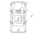
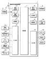
図1は、車両用ドア自動解錠システムの一構成例を示す模式図、図2は、車両用自動解錠装置1の一構成例を示すブロック図である。本実施形態に係る車両用ドア自動解錠システムは、車両Cに設けられた複数のLF送信アンテナ3及びRF受信アンテナ1aを用いて各種信号を送受信する車両用自動解錠装置1と、車両周辺の不審者を監視する監視装置2と、該車両用自動解錠装置1との間で該信号を送受信する携帯機4とを備える。 FIG. 1 is a schematic view showing one configuration example of a vehicle door automatic unlocking system, and FIG. 2 is a block diagram showing one configuration example of a vehicle
車両用自動解錠装置1は、該車両用自動解錠装置1の各構成部の動作を制御する制御部11を備える。制御部11は、例えば一又は複数のCPU(Central Processing Unit)、マルチコアCPU等を有するマイコンである。制御部11には、車載送信部12、車載受信部13、記憶部14、入力部15、車内通信部16、計時部17、駆動部18及び出力部19が設けられている。 The vehicle
制御部11は、記憶部14に記憶されている後述の制御プログラムを実行することにより、各構成部の動作を制御し、不審者の監視及びドアの自動解錠に係る処理を実行する。 The
車載送信部12は複数のLF送信アンテナ3に接続されており、制御部11の制御に従って、携帯機4の位置検出を行うための検出用信号をLF帯の電波を用いて送信する。複数のLF送信アンテナ3は、例えば、車両Cに設けられた各ドア付近に設けられている。 The on-
携帯機4は、車載送信部12から送信された信号を受信するためのLF受信アンテナと、UHF帯の電波を用いて車両用自動解錠装置1へ信号を送信するためのRF送信アンテナと、施錠スイッチと、解錠スイッチとを備える。携帯機4は、検出用信号を受信した場合、当該検出用信号の受信信号強度を測定する。そして、携帯機4は、測定して得た受信信号強度を含む応答信号を、UHF帯の電波を用いて車両用自動解錠装置1へ送信する。また、携帯機4は、施錠スイッチが操作された場合、施錠操作に係る情報を含む施錠操作信号を車両用自動解錠装置1へ送信する。同様に、携帯機4は、解錠スイッチが操作されえた場合、解錠操作に係る情報を含む解錠操作信号を車両用自動解錠装置1へ送信する。 The portable device 4 includes an LF receiving antenna for receiving a signal transmitted from the in-vehicle transmitting
車載受信部13はRF受信アンテナ1aに接続されており、携帯機4からUHF帯の電波を用いて送信された応答信号、解錠操作信号、施錠操作信号等の各種信号を受信する。受信した信号を制御部11へ出力する。制御部11は、車載送信部12及び車載受信部13を用いて携帯機4と無線通信を行い、解錠操作信号、施錠操作信号等の受信処理、携帯機4の認証処理、位置検出処理等を実行する。なお、携帯機4の認証及び位置検出等の処理は、専用ECUにて実行するように構成しても良い。 The on-vehicle receiving
記憶部14は、EEPROM(Electrically Erasable Programmable ROM)、フラッシュメモリ等の不揮発性メモリである。記憶部14は、制御部11が車両用自動解錠装置1の各構成部の動作を制御することにより、不審者の監視及びドアの自動解錠に係る処理を実行するための制御プログラムを記憶している。 The
入力部15には、車速センサ15a、変速段検出スイッチ15b、イグニッション(IG)スイッチ15c、運転席ドアノブスイッチ15d、集中ロックスイッチ15eが接続されている。 Connected to the
車速センサ15aは、例えば車両Cに備えられた車軸の回転数に比例した信号を発信する磁気ピックアップ、ホール素子等を備えた非接触センサ、及び該非接触センサからのパルス数を計測する計数回路を備え、パルス数を計測することによって車両Cの速度を検出する。車速センサ15aにて検出された車速を示す信号は制御部11に入力されるように構成されており、制御部11は、入力部15に入力される当該信号によって、車速を検知する。なお、非接触センサは車速センサ15aの一例であり、かかる構造に限定されるものでは無い。例えば、GPSが検出した車両Cの位置の情報を取得し、車両Cの位置の変化に基づいて、車両Cの速度を検出するように車速センサ15aを構成しても良い。 The
変速段検出スイッチ15bは、車両Cに設けられた変速機の変速段を切り替えるシフトレバーのシフトポジションに応じて状態が切り替わるスイッチであり、スイッチの切替状態に応じた信号が制御部11に入力するように構成されている。制御部11は、入力部15に入力された当該信号によって、シフトポジションの位置を検知する。 The gear
イグニッションスイッチ15cは、車両Cの原動機を始動させるためのスイッチであり、イグニッションスイッチ15cの操作位置に応じた信号が制御部11に入力するように構成されている。制御部11は、イグニッションスイッチ15cの操作位置に応じた信号により、原動機の始動、動作中であるか否かを認識することができる。また、スマートスタート(登録商標)システムが搭載されている車両Cの場合、スマートスタート(登録商標)ボタンの操作による原動機の動作状態に係る信号を受信し、原動機の動作状態を認識するように構成しても良い。 The
運転席ドアノブスイッチ15dは、運転席の車室内側のドアノブの操作状態に応じた信号が制御部11に入力される。制御部11は、当該信号に基づいて、ドアノブの操作状態を認識することができる。 In the driver's seat
集中ロックスイッチ15eは、運転席の車室内側に設けられており、車両Cの全ドアの施錠及び解錠を集中的に操作するためのスイッチであり、当該スイッチの操作状態に応じた信号が制御部11に入力される。制御部11は、当該信号に基づいて、集中ロックスイッチ15eの操作状態を認識することができる。 The
車内通信部16は、CAN(Controller Area Network)又はLIN(Local Interconnect Network)等の通信プロトコルに従って通信を行う通信回路であり、監視装置2に接続されている。車内通信部16は、制御部11の制御に従って、監視装置2の起動を指示する起動信号、監視装置2の停止を指示する停止信号等を送信する。また、車内通信部16は、監視装置2から送信された監視結果を受信し、制御部11は車内通信部16を介して監視結果を取得する。 The in-
計時部17は制御部11の制御に従って計時を開始し、計時結果を制御部11に与える。 The clocking
駆動部18は、ドアロック装置18aに接続されている。ドアロック装置18aは、各ドアの施錠及び解錠を行う施錠機構と、該施錠機構を駆動するアクチュエータとを備える。制御部11は、集中ロックスイッチ15eが操作された場合、各ドアのアクチュエータへ施錠駆動信号又は解錠駆動信号を出力し、各ドアを施錠し又は解錠する。 The
出力部19には、スピーカ19a、室内灯19b及び表示部19cが接続されている。
室内灯19bは、ドアハンドル又はドアの車室内壁の所定部位に設けられた発光素子、車室内の天井部に設けられたルームランプ等である。また、室内灯19bは、赤色、青色等、発光色を切り替えることができる発光素子を備えると良い。制御部11は、オン信号及びオフ信号を出力することによって、室内灯19bの点灯及び消灯、並びに灯色を制御する。
スピーカ19a及び表示部19cは、例えばオーディオ及びナビゲーションシステムを構成している。表示部は、液晶ディスプレイ等である。スピーカ19a及び表示部19cは、制御部11の制御に従って、車両周辺が安全な状況にあること、危険な状況にあることを、音声及び映像にて出力する。また、スピーカ19a及び表示部19cは、危険な状況にある場合、その原因として車両周辺に存在する不審者及び障害物の種別を報知する。A
The
The
なお、図2においては各種スイッチ及び機器が車両用自動解錠装置1の入力部15及び出力部19に直接的に接続されている様に図示しているが、各種スイッチ及び装置は、信号線により直接接続されていても良いし、CAN又はLIN等の車載通信網を介して接続されていても良いし、他のECUを介して接続されていても良い。 In FIG. 2, various switches and devices are illustrated as being directly connected to the
図3は、監視装置2の一構成例を示すブロック図である。監視装置2は、監視制御部21、車内通信部22及び入出力部23を備え、図示しない電源装置から給電されて動作している。監視制御部21は、例えば一又は複数のCPU(Central Processing Unit)、マルチコアCPU等を有するマイコンであり、監視装置2全体の動作を制御している。車内通信部22の構成は、車内通信部16と同様であり、監視制御部21は、車内通信部22を介して車両用自動解錠装置1と各種信号を送受信する。車両用自動解錠装置1から送信された停止信号を車内通信部22が受信した場合、監視装置2はスタンバイ状態へ移行し、その主な動作を停止させる。また、車両用自動解錠装置1から送信された起動信号を車内通信部22が受信した場合、監視装置2はスタンバイ状態から起動し、停止していた動作を再開する。なお、スタンバイ状態は、起動状態に比べて監視装置2の消費電力が低い状態であり、車両用自動解錠装置1から送信される信号を監視する等、車内通信部22の一部の機能のみが動作している状態である。 FIG. 3 is a block diagram showing one configuration example of the
入出力部23には、車載カメラ23a、近接センサ23b、レーダ23c及び音センサ23dが接続されており、各機器の動作は監視制御部21によって制御される。 The in-
車載カメラ23aは、車両周辺を撮像し、撮像して得た画像データを監視制御部21へ出力する。車載カメラ23aは、単眼カメラ、ステレオカメラのいずれも利用することができる。また、車載カメラ23aは、可視光にて不審者を撮像するものであっても良いし、赤外線にて不審者を撮像するものであっても良い。監視制御部21は、入出力部23を介して、車載カメラ23aから画像データを取得する。 The on-
近接センサ23bは、例えば、超音波又は赤外線等によって、車両周辺の不審者及び障害物を検出するセンサであり、検出結果を監視制御部21へ出力する。近接センサ23bは、車両Cの前部若しくは後部の車幅方向両側、又は車両Cの前部若しくは後部の車幅方向略中央部に設けられている。なお、クリアランスソナーを、不審者及び障害物を検出する近接センサ23bとして利用すると良い。 The
レーダ23cは、例えば、ミリ波レーダ、レーザレーダ、超音波レーダ等であり、比較的遠方に存在する不審者及び障害物を検出し、検出結果を監視制御部21へ出力する。 The
監視制御部21は、取得した画像データ、近接センサ23b、レーダ23c、音センサ23dの検出結果を解析することによって、車両周辺に存在する不審者、障害物等を識別ないし検出する。不審者及び障害物の識別は、例えばディープラーニングによって行う。ディープラーニングは、機械学習の一種であり、画像及び各センサの検出結果を所定のクラスに分類するものである。監視制御部21は、車両ドア付近に存在する壁、ブロック等の障害物のオブジェクト画像、不審者のオブジェクト画像、車両周辺に存在する建物、車両等の物体のオブジェクト画像、並びに各オブジェクト画像の移動パターン等を大量に学習し、不審者及び障害物の特徴と、各特徴に対応するクラスとを学習結果として記憶している。監視制御部21は、取得した画像データ及び各センサの検出結果と、学習結果とに基づいて、検出対象が属するクラスを特定する。クラスの特定によって、検出対象が不審者であるか否か、不審者及び障害物の種別等が特定される。監視制御部21は、不審者及び障害物の有無、不審者及び障害物の種別等、不審者等に係る検出結果を車内通信部22にて車両用自動解錠装置1へ送信する。 The
図4は、自動解錠に係る制御部11の処理手順を示すフローチャートである。制御部11は、変速段検出スイッチ15b、イグニッションスイッチ15c等から入力部15に入力される信号に基づいて、所定のアンロック条件を充足するか否かを判定する(ステップS11)。所定のアンロック条件は、本態様(1)に係る所定の走行停止状態に対応する。アンロック条件は、例えば、車速がゼロ、イグニッションスイッチ15cがオフ状態にあって、シフトレバーのシフトポジションがパーキングにある状態である。
また、制御部11は、車載受信部13にて携帯機4から送信された解錠操作信号を受信し、携帯機4の認証に成功し、無線通信により携帯機4が車内にあることを検知した場合、所定のアンロック条件を充足すると判定しても良い。
更に、制御部11は、イグニッションスイッチ15cがオフ状態にあって、運転席ドアノブスイッチ15dにて、運転席のドアノブが操作されたことを検知した場合、所定のアンロック条件を充足すると判定しても良い。FIG. 4 is a flowchart showing the processing procedure of the
Further, the
Furthermore, when the
アンロック条件を充足しないと判定した場合(ステップS11:NO)、制御部11は、処理をステップS11へ戻す。アンロック条件を充足すると判定した場合(ステップS11:YES)、制御部11は、車内通信部16にて起動信号を監視装置2へ送信することによって、監視装置2を起動させ、車両周辺の監視を開始させる(ステップS12)。 When it is determined that the unlock condition is not satisfied (step S11: NO), the
次いで、制御部11は、監視装置2から送信される不審者等に係る検出結果を車内通信部16にて受信し、該検出結果に基づいて、不審者又は障害物が存在しないか否かを判定する(ステップS13)。なお、ステップS12及びステップS13の処理を実行する制御部11は、上記態様(1)の監視部に対応する。
不審者及び障害物が存在しないと判定した場合(ステップS13:YES)、制御部11は、スピーカ19a、室内灯19b及び表示部19c等を用いて、車外が安全である旨を報知する(ステップS14)。例えば、スピーカ19aにて「ドアを開けてください」の音声を出力する。また、室内灯19bを青色で発光させる。なお、ステップS14の処理を実行する制御部11は、安全状態報知部に対応する。
そして、制御部11は、駆動部18からドアロック装置18aへ解錠駆動信号を出力し、車両Cの全ドアを解錠させ(ステップS15)、処理を終える。Next, the
When it is determined that the suspicious person and the obstacle do not exist (step S13: YES), the
Then, the
ステップS13において不審者又は障害物が存在すると判定した場合(ステップS13:NO)、制御部11は、スピーカ19a、室内灯19b及び表示部19c等を用いて、車外が危険である旨を報知する(ステップS16)。例えば、スピーカ19aにて「危険があるため待機してください」の音声を出力する。また、室内灯19bを赤色で発光させる。また、制御部11は、スピーカ19a、室内灯19b及び表示部19c等を用いて、不審者及び障害物の種別を報知する(ステップS17)。例えば、車両周辺の不審者を検知した場合、スピーカ19aにて「不審者が存在します」の音声を出力し、障害物を検知した場合、スピーカ19aにて「障害物が存在します」等の音声を出力する。
なお、ステップS16及びステップS17の処理を実行する制御部11は、上記態様(2)及び態様(3)の危険状態報知部に対応する。If it is determined in step S13 that a suspicious individual or an obstacle is present (step S13: NO), the
In addition, the
次いで、制御部11は、集中ロックスイッチ15eを用いた手動解錠操作が行われたか否かを判定する(ステップS18)。なお、ステップS18の処理を実行する制御部11は、態様(4)の解錠操作検知部に対応する。手動解錠操作が行われていないと判定した場合(ステップS18:NO)、制御部11は処理をステップS13へ戻す。手動解錠操作が行われたと判定した場合(ステップS18:YES)、制御部11は、ドアロック装置18aにて車両Cの全ドアを解錠させ(ステップS15)、処理を終える。
なお、ここでは、集中ロックスイッチ15eにて、ドアの解錠を行う例を説明したが、各ドアに設けられたドアロックメカスイッチが操作された場合、各ドアを解錠するように構成しても良い。Next, the
Although the example in which the doors are unlocked by the
このように構成された、車両用自動解錠装置1によれば、使用者が降車する可能性がある所定の走行停止状態になった際に車両周辺の不審者を監視し、不審者が存在しないことを確認した上で車両のドアを自動的に解錠することができる。従って、車両周辺に注意すること無く、使用者がドアを開けることによって起こる犯罪又は事故を防止することができ、使用者の安全性を向上させることができる。 According to the automatic unlocking
また、車両用自動解錠装置1は、不審者が検知された場合、ドアの施錠状態を保持すると共に、危険を報知することができる。従って、使用者は、自動解錠機能の故障では無く、車外に何らかの危険があるためにドアの自動解錠が行われていないことを認識することができる。 In addition, when a suspicious person is detected, the automatic unlocking
更に、車両用自動解錠装置1は、不審者及び障害物の種別を報知することができる。従って、使用者は、車外にどのような危険があるためにドアの自動解錠が行われていないかを認識することができる。例えば、使用者は、車両のドアを開けた際にぶつかりそうな障害物が存在するのか、それとも不審な人物が存在するのか、危険の原因を認識することができる。 Furthermore, the automatic unlocking
更にまた、車両用自動解錠装置1は不審者が検知され、ドアの施錠状態が保持されている状況にあっても、集中ロックスイッチ15eの操作によって、ドアを解錠することができる。従って、車両用自動解錠装置1が危険と判断している状況にあっても、使用者が車外の安全を確認できた場合、使用者の意思でドアを解錠することができる。 Furthermore, in the automatic unlocking
更にまた、車両用自動解錠装置1は不審者が検知されなかった場合、安全である旨を報知することができる。従って、使用者は、車外が安全な状態にあることを認識することができる。 Furthermore, the automatic unlocking
1 車両用自動解錠装置
1a RF受信アンテナ
2 監視装置
3 LF送信アンテナ
4 携帯機
11 制御部
12 車載送信部
13 車載受信部
14 記憶部
15 入力部
15a 車速センサ
15b 変速段検出スイッチ
15c イグニッションスイッチ
15d 運転席ドアノブスイッチ
15e 集中ロックスイッチ
16 車内通信部
17 計時部
18 駆動部
18a ドアロック装置
19 出力部
19a スピーカ
19b 室内灯
19c 表示部
21 監視制御部
22 車内通信部
23 入出力部
23a 車載カメラ
23b 近接センサ
23c レーダ
23d 音センサ
C 車両1 Automatic
Claims (3)
Translated fromJapanese前記所定の走行停止状態になった場合、車両周辺の不審者を監視する監視部と、
該監視部にて不審者が検知された場合、前記ドアの施錠状態を保持し、前記監視部にて不審者が検知されなかった場合、前記ドアを解錠する駆動部と、
前記監視部にて不審者が検知され、前記ドアの施錠状態が保持されている場合、危険を報知する危険状態報知部と
を備え、
前記監視部は、
前記車両周辺の不審者及び障害物を監視しており、
前記危険状態報知部は、
少なくとも前記監視部にて検知された不審者及び障害物の種別を報知する
車両用自動解錠装置。An automatic unlocking device for a vehicle, which automatically unlocks a locked door of the vehicle when the vehicle is in a predetermined traveling stop state,
A monitoring unit that monitors a suspicious person around the vehicle when the predetermined traveling stop state is reached;
A driving unit that holds a locked state of the door when a suspicious person is detected by the monitoring unit, and unlocks the door when the suspicious person is not detected by the monitoring unit;
The monitoring unit includesa dangerous state notification unit that detects a suspicious person and detects a danger when the locked state of the door is held.
The monitoring unit
Monitors suspicious persons and obstacles around the vehicle,
The dangerous condition notification unit
The automatic unlocking device for vehicles which reportsthe kind of the suspicious person and the obstacle which were detected by the monitoring part at least .
前記駆動部は、
前記所定の走行停止状態で前記ドアの施錠状態が保持されており、前記解錠操作検知部にて解錠操作を検知した場合、前記ドアを解錠する
請求項1に記載の車両用自動解錠装置。And an unlocking operation detection unit configured to detect an unlocking operation of the door;
The drive unit is
The locked state of the door is held in the predetermined traveling stop state, and when the unlocking operation is detected by the unlocking operation detection unit, the door is unlocked.
The automatic unlocking device for a vehicle according toclaim 1 .
請求項1又は請求項2に記載の車両用自動解錠装置。The automatic unlocking device for a vehicle according toclaim 1or 2 , further comprising a safety state notification unit that notifies that it is safe when a suspicious person is not detected by the monitoring unit.
Priority Applications (4)
| Application Number | Priority Date | Filing Date | Title |
|---|---|---|---|
| JP2016037332AJP6520760B2 (en) | 2016-02-29 | 2016-02-29 | Automatic unlocking device for vehicles |
| PCT/JP2017/004575WO2017150113A1 (en) | 2016-02-29 | 2017-02-08 | Automatic unlocking device for vehicles |
| CN201780010649.3ACN108884692A (en) | 2016-02-29 | 2017-02-08 | Automatic unlocking device for vehicles |
| US16/075,214US20190176737A1 (en) | 2016-02-29 | 2017-02-08 | Automatic unlocking device for vehicles |
Applications Claiming Priority (1)
| Application Number | Priority Date | Filing Date | Title |
|---|---|---|---|
| JP2016037332AJP6520760B2 (en) | 2016-02-29 | 2016-02-29 | Automatic unlocking device for vehicles |
Publications (3)
| Publication Number | Publication Date |
|---|---|
| JP2017155422A JP2017155422A (en) | 2017-09-07 |
| JP2017155422A5 JP2017155422A5 (en) | 2018-08-09 |
| JP6520760B2true JP6520760B2 (en) | 2019-05-29 |
Family
ID=59742882
Family Applications (1)
| Application Number | Title | Priority Date | Filing Date |
|---|---|---|---|
| JP2016037332AActiveJP6520760B2 (en) | 2016-02-29 | 2016-02-29 | Automatic unlocking device for vehicles |
Country Status (4)
| Country | Link |
|---|---|
| US (1) | US20190176737A1 (en) |
| JP (1) | JP6520760B2 (en) |
| CN (1) | CN108884692A (en) |
| WO (1) | WO2017150113A1 (en) |
Cited By (1)
| Publication number | Priority date | Publication date | Assignee | Title |
|---|---|---|---|---|
| WO2023007515A1 (en)* | 2021-07-27 | 2023-02-02 | Ola Electric Mobility Private Limited | Automatic locking and unlocking of vehicles |
Families Citing this family (16)
| Publication number | Priority date | Publication date | Assignee | Title |
|---|---|---|---|---|
| US10233679B1 (en) | 2016-04-11 | 2019-03-19 | State Farm Mutual Automobile Insurance Company | Systems and methods for control systems to facilitate situational awareness of a vehicle |
| US10872379B1 (en) | 2016-04-11 | 2020-12-22 | State Farm Mutual Automobile Insurance Company | Collision risk-based engagement and disengagement of autonomous control of a vehicle |
| US10222228B1 (en) | 2016-04-11 | 2019-03-05 | State Farm Mutual Automobile Insurance Company | System for driver's education |
| US10486708B1 (en) | 2016-04-11 | 2019-11-26 | State Farm Mutual Automobile Insurance Company | System for adjusting autonomous vehicle driving behavior to mimic that of neighboring/surrounding vehicles |
| US11851041B1 (en) | 2016-04-11 | 2023-12-26 | State Farm Mutual Automobile Insurance Company | System for determining road slipperiness in bad weather conditions |
| US10247565B2 (en) | 2016-04-11 | 2019-04-02 | State Farm Mutual Automobile Insurance Company | Traffic risk avoidance for a route selection system |
| US10026309B1 (en) | 2016-04-11 | 2018-07-17 | State Farm Mutual Automobile Insurance Company | Networked vehicle control systems to facilitate situational awareness of vehicles |
| US10019904B1 (en) | 2016-04-11 | 2018-07-10 | State Farm Mutual Automobile Insurance Company | System for identifying high risk parking lots |
| US10613537B2 (en)* | 2016-12-31 | 2020-04-07 | Lyft Inc. | Autonomous vehicle pickup and drop-off management |
| KR102586445B1 (en)* | 2018-08-08 | 2023-10-06 | 현대자동차주식회사 | System for sensing height of obstacle for parking assistance |
| KR102113344B1 (en)* | 2018-08-17 | 2020-05-20 | 주식회사 한국모바일택시복지사업단 | Auto open and shut system for door of vehicle |
| CN110232828A (en)* | 2019-07-29 | 2019-09-13 | 深圳市万泊科技有限公司 | A kind of a variety of aiding sensors fusion detection methods based on geomagnetic sensor |
| JP7517025B2 (en)* | 2020-09-24 | 2024-07-17 | 株式会社Jvcケンウッド | Vehicle control device and vehicle control method |
| CN113353089B (en)* | 2021-06-10 | 2022-10-25 | 东风华神汽车有限公司 | Vehicle safe driving control method, device and equipment and readable storage medium |
| US12351129B2 (en) | 2022-04-25 | 2025-07-08 | Toyota Research Institute, Inc. | Systems and methods to utilize user trajectory analysis for automatic vehicle controls |
| JP2025088409A (en)* | 2023-11-30 | 2025-06-11 | 本田技研工業株式会社 | Control device, program and vehicle |
Family Cites Families (8)
| Publication number | Priority date | Publication date | Assignee | Title |
|---|---|---|---|---|
| CN2056136U (en)* | 1989-10-19 | 1990-04-18 | 朱华锷 | Multi-azimuth burglar alarm for vehicle |
| JP5016499B2 (en)* | 2008-01-17 | 2012-09-05 | フジ電機工業株式会社 | Door unlocking device |
| US8378800B2 (en)* | 2009-09-30 | 2013-02-19 | Dei Headquarters, Inc. | Security system and method for operating the same |
| DE102010029780A1 (en)* | 2010-06-08 | 2011-12-22 | Robert Bosch Gmbh | Device for lateral environment monitoring of a vehicle |
| US20130234844A1 (en)* | 2012-03-12 | 2013-09-12 | Ford Global Technologies, Llc | Door opening warning based on approaching objects |
| JP2013216251A (en)* | 2012-04-11 | 2013-10-24 | Mitsubishi Motors Corp | Surrounding condition monitoring device |
| US8979160B1 (en)* | 2013-08-23 | 2015-03-17 | Ford Global Technologies, Llc | System and apparatus for providing a secure storage compartment |
| CN104442660A (en)* | 2014-11-10 | 2015-03-25 | 无锡悟莘科技有限公司 | Door control method for vehicle parking |
- 2016
- 2016-02-29JPJP2016037332Apatent/JP6520760B2/enactiveActive
- 2017
- 2017-02-08CNCN201780010649.3Apatent/CN108884692A/enactivePending
- 2017-02-08WOPCT/JP2017/004575patent/WO2017150113A1/ennot_activeCeased
- 2017-02-08USUS16/075,214patent/US20190176737A1/ennot_activeAbandoned
Cited By (1)
| Publication number | Priority date | Publication date | Assignee | Title |
|---|---|---|---|---|
| WO2023007515A1 (en)* | 2021-07-27 | 2023-02-02 | Ola Electric Mobility Private Limited | Automatic locking and unlocking of vehicles |
Also Published As
| Publication number | Publication date |
|---|---|
| WO2017150113A1 (en) | 2017-09-08 |
| CN108884692A (en) | 2018-11-23 |
| US20190176737A1 (en) | 2019-06-13 |
| JP2017155422A (en) | 2017-09-07 |
Similar Documents
| Publication | Publication Date | Title |
|---|---|---|
| JP6520760B2 (en) | Automatic unlocking device for vehicles | |
| US10388091B2 (en) | Vehicle remote control system and vehicle-mounted apparatus incorporated in the same | |
| US10308223B2 (en) | In-vehicle device and vehicle security system | |
| US10625734B2 (en) | Automatic driving system for automatically driven vehicle | |
| US9452732B1 (en) | Vehicle key off load reduction via off-board sensor | |
| US10586226B2 (en) | Integration of vehicle boundary alert system with external transaction equipment | |
| US9783160B2 (en) | Door unlocking system | |
| US8237544B2 (en) | Automatic door control system and method | |
| CN105894810B (en) | Method and device for monitoring a vehicle travelling in a parking area | |
| US9764699B2 (en) | Position-based performance of a vehicle function in a vehicle communication system | |
| JP5946018B2 (en) | Vehicle door opening and closing system | |
| US20070120644A1 (en) | Smart entry system and warning method thereof | |
| JP2016528082A (en) | Providing status indicators to users in vehicle communication systems | |
| JP2011111070A (en) | Device, system, and method of detecting approaching object | |
| EP1953051A2 (en) | Antitheft device for vehicle | |
| JP2013216251A (en) | Surrounding condition monitoring device | |
| JP2017155423A (en) | On-vehicle apparatus and vehicle security system | |
| JP2017182347A (en) | Vehicle communication system, vehicle peripheral information transmission method, and control program | |
| WO2017169735A1 (en) | Surrounding obstacle notification device and surrounding obstacle notification system | |
| JP5550949B2 (en) | Vehicle locking device | |
| JP2014020123A (en) | Smart entry system | |
| JP2017198018A (en) | Vehicle control device |
Legal Events
| Date | Code | Title | Description |
|---|---|---|---|
| A621 | Written request for application examination | Free format text:JAPANESE INTERMEDIATE CODE: A621 Effective date:20180530 | |
| A521 | Request for written amendment filed | Free format text:JAPANESE INTERMEDIATE CODE: A523 Effective date:20180627 | |
| A131 | Notification of reasons for refusal | Free format text:JAPANESE INTERMEDIATE CODE: A131 Effective date:20181204 | |
| A521 | Request for written amendment filed | Free format text:JAPANESE INTERMEDIATE CODE: A523 Effective date:20190128 | |
| TRDD | Decision of grant or rejection written | ||
| A01 | Written decision to grant a patent or to grant a registration (utility model) | Free format text:JAPANESE INTERMEDIATE CODE: A01 Effective date:20190402 | |
| A61 | First payment of annual fees (during grant procedure) | Free format text:JAPANESE INTERMEDIATE CODE: A61 Effective date:20190415 | |
| R150 | Certificate of patent or registration of utility model | Ref document number:6520760 Country of ref document:JP Free format text:JAPANESE INTERMEDIATE CODE: R150 | |
| R250 | Receipt of annual fees | Free format text:JAPANESE INTERMEDIATE CODE: R250 | |
| R250 | Receipt of annual fees | Free format text:JAPANESE INTERMEDIATE CODE: R250 |