JP6516219B2 - Photodynamic therapy light irradiator - Google Patents
Photodynamic therapy light irradiatorDownload PDFInfo
- Publication number
- JP6516219B2 JP6516219B2JP2015126336AJP2015126336AJP6516219B2JP 6516219 B2JP6516219 B2JP 6516219B2JP 2015126336 AJP2015126336 AJP 2015126336AJP 2015126336 AJP2015126336 AJP 2015126336AJP 6516219 B2JP6516219 B2JP 6516219B2
- Authority
- JP
- Japan
- Prior art keywords
- light
- wavelength
- led element
- irradiation
- light source
- Prior art date
- Legal status (The legal status is an assumption and is not a legal conclusion. Google has not performed a legal analysis and makes no representation as to the accuracy of the status listed.)
- Active
Links
- 238000002428photodynamic therapyMethods0.000titleclaimsdescription64
- 230000007246mechanismEffects0.000claimsdescription15
- 239000003504photosensitizing agentSubstances0.000description22
- 230000000694effectsEffects0.000description18
- 230000003833cell viabilityEffects0.000description15
- KSFOVUSSGSKXFI-GAQDCDSVSA-NCC1=C/2NC(\C=C3/N=C(/C=C4\N\C(=C/C5=N/C(=C\2)/C(C=C)=C5C)C(C=C)=C4C)C(C)=C3CCC(O)=O)=C1CCC(O)=OChemical compoundCC1=C/2NC(\C=C3/N=C(/C=C4\N\C(=C/C5=N/C(=C\2)/C(C=C)=C5C)C(C=C)=C4C)C(C)=C3CCC(O)=O)=C1CCC(O)=OKSFOVUSSGSKXFI-GAQDCDSVSA-N0.000description13
- 230000003902lesionEffects0.000description13
- 229950003776protoporphyrinDrugs0.000description12
- ZGXJTSGNIOSYLO-UHFFFAOYSA-N88755TAZ87Chemical compoundNCC(=O)CCC(O)=OZGXJTSGNIOSYLO-UHFFFAOYSA-N0.000description11
- 230000001225therapeutic effectEffects0.000description11
- 210000004027cellAnatomy0.000description9
- 239000000126substanceSubstances0.000description8
- 239000002243precursorSubstances0.000description7
- 238000001228spectrumMethods0.000description7
- 238000010521absorption reactionMethods0.000description5
- 238000009792diffusion processMethods0.000description5
- 201000010099diseaseDiseases0.000description5
- 208000037265diseases, disorders, signs and symptomsDiseases0.000description5
- 230000005855radiationEffects0.000description5
- 230000002195synergetic effectEffects0.000description5
- QNRATNLHPGXHMA-XZHTYLCXSA-N(r)-(6-ethoxyquinolin-4-yl)-[(2s,4s,5r)-5-ethyl-1-azabicyclo[2.2.2]octan-2-yl]methanol;hydrochlorideChemical compoundCl.C([C@H]([C@H](C1)CC)C2)CN1[C@@H]2[C@H](O)C1=CC=NC2=CC=C(OCC)C=C21QNRATNLHPGXHMA-XZHTYLCXSA-N0.000description4
- 208000002874Acne VulgarisDiseases0.000description4
- 206010000496acneDiseases0.000description4
- 208000009621actinic keratosisDiseases0.000description4
- LOKCTEFSRHRXRJ-UHFFFAOYSA-Idipotassium trisodium dihydrogen phosphate hydrogen phosphate dichlorideChemical compoundP(=O)(O)(O)[O-].[K+].P(=O)(O)([O-])[O-].[Na+].[Na+].[Cl-].[K+].[Cl-].[Na+]LOKCTEFSRHRXRJ-UHFFFAOYSA-I0.000description4
- 238000005286illuminationMethods0.000description4
- 238000001727in vivoMethods0.000description4
- 239000002953phosphate buffered salineSubstances0.000description4
- 210000001519tissueAnatomy0.000description4
- 208000013165Bowen diseaseDiseases0.000description3
- 208000019337Bowen disease of the skinDiseases0.000description3
- 238000000862absorption spectrumMethods0.000description3
- 230000002165photosensitisationEffects0.000description3
- 239000000758substrateSubstances0.000description3
- 230000004083survival effectEffects0.000description3
- 206010004146Basal cell carcinomaDiseases0.000description2
- 230000002159abnormal effectEffects0.000description2
- 230000002411adverseEffects0.000description2
- 238000002737cell proliferation kitMethods0.000description2
- 238000013461designMethods0.000description2
- 238000006911enzymatic reactionMethods0.000description2
- 230000001678irradiating effectEffects0.000description2
- 210000002510keratinocyteAnatomy0.000description2
- 239000010410layerSubstances0.000description2
- 230000001613neoplastic effectEffects0.000description2
- 230000003287optical effectEffects0.000description2
- 230000000171quenching effectEffects0.000description2
- 239000011347resinSubstances0.000description2
- 229920005989resinPolymers0.000description2
- 238000000926separation methodMethods0.000description2
- 239000000243solutionSubstances0.000description2
- 238000012360testing methodMethods0.000description2
- 208000010191Osteitis DeformansDiseases0.000description1
- 208000027868Paget diseaseDiseases0.000description1
- VYPSYNLAJGMNEJ-UHFFFAOYSA-NSilicium dioxideChemical compoundO=[Si]=OVYPSYNLAJGMNEJ-UHFFFAOYSA-N0.000description1
- 206010047571Visual impairmentDiseases0.000description1
- 229960002749aminolevulinic acidDrugs0.000description1
- 230000005540biological transmissionEffects0.000description1
- 150000001875compoundsChemical class0.000description1
- 238000012258culturingMethods0.000description1
- 238000010586diagramMethods0.000description1
- 238000006073displacement reactionMethods0.000description1
- 239000003814drugSubstances0.000description1
- 238000002474experimental methodMethods0.000description1
- 239000000835fiberSubstances0.000description1
- 206010020718hyperplasiaDiseases0.000description1
- LCPSIJJDZWNVRJ-UHFFFAOYSA-Lin-protoporphyrin ixChemical compoundC1=C(N2[In]N34)C(C=C)=C(C)C2=CC(=N2)C(C)=C(CCC(O)=O)C2=CC3=C(CCC(O)=O)C(C)=C4C=C2C(C=C)=C(C)C1=N2LCPSIJJDZWNVRJ-UHFFFAOYSA-L0.000description1
- 208000027202mammary Paget diseaseDiseases0.000description1
- 239000000463materialSubstances0.000description1
- 229910001507metal halideInorganic materials0.000description1
- 150000005309metal halidesChemical class0.000description1
- 238000012986modificationMethods0.000description1
- 230000004048modificationEffects0.000description1
- 230000002093peripheral effectEffects0.000description1
- -1porphyrin compoundChemical class0.000description1
- 239000003642reactive oxygen metaboliteSubstances0.000description1
- 210000001732sebaceous glandAnatomy0.000description1
- 210000003491skinAnatomy0.000description1
- 239000002344surface layerSubstances0.000description1
- 238000002560therapeutic procedureMethods0.000description1
- 229910052724xenonInorganic materials0.000description1
- FHNFHKCVQCLJFQ-UHFFFAOYSA-Nxenon atomChemical compound[Xe]FHNFHKCVQCLJFQ-UHFFFAOYSA-N0.000description1
Images


Classifications
- A—HUMAN NECESSITIES
- A61—MEDICAL OR VETERINARY SCIENCE; HYGIENE
- A61N—ELECTROTHERAPY; MAGNETOTHERAPY; RADIATION THERAPY; ULTRASOUND THERAPY
- A61N5/00—Radiation therapy
- A61N5/06—Radiation therapy using light
- A61N5/0613—Apparatus adapted for a specific treatment
- A61N5/062—Photodynamic therapy, i.e. excitation of an agent
- A—HUMAN NECESSITIES
- A61—MEDICAL OR VETERINARY SCIENCE; HYGIENE
- A61K—PREPARATIONS FOR MEDICAL, DENTAL OR TOILETRY PURPOSES
- A61K41/00—Medicinal preparations obtained by treating materials with wave energy or particle radiation ; Therapies using these preparations
- A61K41/0057—Photodynamic therapy with a photosensitizer, i.e. agent able to produce reactive oxygen species upon exposure to light or radiation, e.g. UV or visible light; photocleavage of nucleic acids with an agent
- A—HUMAN NECESSITIES
- A61—MEDICAL OR VETERINARY SCIENCE; HYGIENE
- A61N—ELECTROTHERAPY; MAGNETOTHERAPY; RADIATION THERAPY; ULTRASOUND THERAPY
- A61N5/00—Radiation therapy
- A61N5/06—Radiation therapy using light
- A61N2005/065—Light sources therefor
- A61N2005/0651—Diodes
- A61N2005/0652—Arrays of diodes
- A—HUMAN NECESSITIES
- A61—MEDICAL OR VETERINARY SCIENCE; HYGIENE
- A61N—ELECTROTHERAPY; MAGNETOTHERAPY; RADIATION THERAPY; ULTRASOUND THERAPY
- A61N5/00—Radiation therapy
- A61N5/06—Radiation therapy using light
- A61N2005/0658—Radiation therapy using light characterised by the wavelength of light used
- A61N2005/0662—Visible light
- A61N2005/0663—Coloured light
- A—HUMAN NECESSITIES
- A61—MEDICAL OR VETERINARY SCIENCE; HYGIENE
- A61N—ELECTROTHERAPY; MAGNETOTHERAPY; RADIATION THERAPY; ULTRASOUND THERAPY
- A61N5/00—Radiation therapy
- A61N5/06—Radiation therapy using light
- A61N5/0613—Apparatus adapted for a specific treatment
- A61N5/0616—Skin treatment other than tanning
Landscapes
- Health & Medical Sciences (AREA)
- Life Sciences & Earth Sciences (AREA)
- Biomedical Technology (AREA)
- Engineering & Computer Science (AREA)
- Animal Behavior & Ethology (AREA)
- General Health & Medical Sciences (AREA)
- Veterinary Medicine (AREA)
- Public Health (AREA)
- Biophysics (AREA)
- Pathology (AREA)
- Radiology & Medical Imaging (AREA)
- Nuclear Medicine, Radiotherapy & Molecular Imaging (AREA)
- Chemical & Material Sciences (AREA)
- Biochemistry (AREA)
- Molecular Biology (AREA)
- Medicinal Chemistry (AREA)
- Pharmacology & Pharmacy (AREA)
- Epidemiology (AREA)
- Radiation-Therapy Devices (AREA)
Description
Translated fromJapanese本発明は、光線力学的治療用光照射装置に関する。 The present invention relates to a light irradiation device for photodynamic therapy.
従来、光を用いた治療法の1つに光線力学的治療法(Photodynamic therapy、以下、「PDT」ともいう。)が知られている。PDTとは、生体内の病変部(病変異常組織)に親和性を有する光増感性物質の性質、具体的には病変部に特異的に蓄積される性質を利用し、生体内に光増感性物質または光増感性物質の前駆物質を投与した後、光増感性物質(生体内において光増感性物質の前駆物質から合成された光増感性物質を含む)に対して光(可視光線)を照射し、組織内で生成した活性酸素種を用いて、病変異常組織のみを選択的に破壊する治療法である。そして、近年、皮膚科分野において、PDTは、日光角化症、ボーエン病、パジェット病および基底細胞癌等の腫瘍性病変、重度の尋常性ざ瘡、脂腺増殖症、並びに難治性疣贅などの治療において広く用いられつつある。Conventionally, photodynamic therapy (hereinafter, also referred to as "PDT") is known as one of the therapeutic methods using light. PDT refers to the property of a photosensitizer having an affinity for a lesion in a living body (lesion-affected tissue), specifically, the property of being accumulated specifically in the lesion, and thus photosensitizing in vivo. After administration of a substance or a precursor of a photosensitizer, light (visible light) is irradiated to the photosensitizer (including a photosensitizer synthesized from a precursor of the photosensitizer in vivo) It is a treatment that selectively destroys only the lesion abnormal tissue using reactive oxygen species generated in the tissue. In recent years, in dermatology field, PDT is actinic keratosis, Bowen's disease, neoplastic lesions, such as Paget's disease and basal cell carcinoma, severe acne vulgaris, sebaceousgland hyperplasia, and intractable warts such as Is being widely used in the treatment of
このようなPDTを実施するための光線力学的治療用光照射装置(以下、「PDT装置」ともいう。)において、光源としては、一般的に、波長600〜700nmのレーザ光源が用いられている。レーザ光源は、放射輝度が高く、また照射面積(スポット径)が小さいことから、ファイバなどの伝送光学素子を用いた装置設計が容易であるなどのメリットがあるため、病変部が小さい範囲の疾患に対しては効率のよい光源である。しかしながら、日光角化症、ボーエン病、基底細胞癌等、ざ瘡などに代表される皮膚科における疾患では病変部が広範囲であることが多いため、照射面積が小さなレーザ光源を用いたPDT装置によっては治療のための照射時間が長くなる、という問題がある。
また、PDT装置としては、光源として、キセノンランプやメタルハライドランプなどに代表されるランプを用いたものが開発、上市されている。しかしながら、ランプを光源とするPDT装置においては、ランプから赤外線が放射されることから、その赤外線に起因して生じる問題、具体的には照射領域において熱感が生じる、という問題がある。In the light irradiation apparatus for photodynamic therapy for carrying out such PDT (hereinafter, also referred to as "PDT apparatus"), a laser light source having a wavelength of 600 to 700 nm is generally used as a light source. . The laser light source has advantages such as easy design of a device using a transmission optical element such as a fiber because the radiance is high and the irradiation area (spot diameter) is small. Is an efficient light source. However, the disease area in dermatology such as actinic keratosis, Bowen's disease, basal cell carcinoma and so on, which are represented by acne, etc. is often widespread, so PDT equipment using a laser light source with a small irradiation area There is a problem that the irradiation time for treatment becomes long.
In addition, as a PDT device, one using a lamp represented by a xenon lamp or a metal halide lamp as a light source has been developed and marketed. However, in a PDT device using a lamp as a light source, since infrared light is emitted from the lamp, there is a problem caused by the infrared light, specifically, there is a problem that heat is generated in the irradiated area.
而して、近年においては、これらの問題を解消すべく、光源としてLED素子を用いたPDT装置が提案されてきている(例えば、特許文献1参照。)。
具体的に、特許文献1には、光源として、異なる波長域の光を放射する2種のLED素子を備え、その2種のLED素子からの異なる2つの光を、同一の照射部位に対して同時にパルス照射するPDT装置が開示されている。このPDT装置において、同時に放射される異なる2つの光は、用いる光増感性物質が感応する最大吸収ピーク波長に合致する波長域(具体的には、波長400〜550nmの範囲、以下「感応波長域」ともいう。)の光と、その感応波長域以外の波長域(具体的には、590〜690nmの範囲)の光とである。つまりは、このPDT装置においては、2種のLED素子の1つとして、病変部に蓄積された光増感性物質の感応波長域に合致する波長域の光を放射するものを選択的に用い、他の1つのLED素子として、感応波長域以外の波長域を有するものを選択的に用いることが必要とされる。In recent years, in order to solve these problems, a PDT device using an LED element as a light source has been proposed (see, for example, Patent Document 1).
Specifically,
一方、光増感性物質および光増感性物質の前駆物質としては、δ−アミノレブリン酸(5-ALA)などのように、わが国においては2014年7月にようやく医療認可(薬事許可)がなされ、新たに用いられ始めたものがある。ここに、「δ−アミノレブリン酸」は、光増感性物質の前駆物質であって、それ自体が光増感性を有するものではなく、このδ−アミノレブリン酸から酵素反応を経て合成されるプロトポルフィリンIX(PpIX)が光増感性物質として機能するものである。そのため、実際の医療現場においては、新たな光増感性物質を用いて有効な治療をするためにどのような波長域の光を照射することが有用であるのかは知られていない。
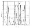
ここに、プロトポルフィリンIX(PpIX)は、図13において破線によって示すような吸収スペクトルを有しており、波長410nm、波長510nm、波長545nm、波長580nmおよび波長630nmに吸収ピークを有し、波長410nmの光、波長510nmの光、波長545nmの光、波長580nmの光および波長630nmの光の順に、吸光度が大きいものである。一方、これらの光の生体深達性は、波長410nmの光、波長510nmの光、波長545nmの光、波長580nmの光および波長630nmの光の順に大きくなる。
図13においては、プロトポルフィリンIXの吸収スペクトルと共に、このプロトポルフィリンIXの吸収ピークの各々に相当するピーク波長を有する5種のLED素子の光強度を示すスペクトルが、曲線(a)〜曲線(e)によって示されている。曲線(a)は、波長405nmにピーク波長を有するLED素子の光強度を示すスペクトルであり、曲線(b)は、波長505nmにピーク波長を有するLED素子の光強度を示すスペクトルであり、曲線(c)は、波長545nmにピーク波長を有するLED素子の光強度を示すスペクトルであり、曲線(d)は、波長570nmにピーク波長を有するLED素子の光強度を示すスペクトルであり、曲線(e)は、波長635nmにピーク波長を有するLED素子の光強度を示すスペクトルである。On the other hand, as photosensitizers and precursors of photosensitizers, such as δ-aminolevulinic acid (5-ALA), medical approval (medicine approval) was finally made in July 2014 in Japan, and new Have begun to be used for Here, “δ-aminolevulinic acid” is a precursor of a photosensitizer, which is not itself a photosensitizer, and is aprotoporphyrin IX synthesized from this δ-aminolevulinic acid through an enzyme reaction. (PpIX) functions as a photosensitizer. Therefore, in actual medical settings, it is not known what wavelength range of light is useful for effective treatment with a new photosensitizer.
Here,protoporphyrin IX (PpIX) has an absorption spectrum as shown by a broken line in FIG. 13, and has absorption peaks at wavelengths 410 nm, 510 nm, 545 nm, 580 nm and 630 nm, and 410 nm The light absorbency is large in the following order: light of wavelength 510 nm, light of
In FIG. 13, together with the absorption spectrum ofprotoporphyrin IX, the spectra showing the light intensities of five types of LED elements having peak wavelengths corresponding to each of the absorption peaks ofprotoporphyrin IX are shown by curves (a) to (e). Is indicated by). Curve (a) is a spectrum showing the light intensity of the LED element having a peak wavelength at 405 nm, and curve (b) is a spectrum showing the light intensity of the LED element having a peak wavelength at 505 nm. c) is a spectrum showing the light intensity of the LED element having a peak wavelength at 545 nm, curve (d) is a spectrum showing the light intensity of the LED element having a peak wavelength at 570 nm, and curve (e) These are the spectra which show the light intensity of the LED element which has a peak wavelength in
而して、本発明者らは、以上のような事情に基づいて、光源としてLED素子を用いたPDT装置について鋭意研究を重ねた結果、光増感性物質としてプロトポルフィリンIX(PpIX)を用いた場合においても、それぞれ特定の波長範囲にピーク波長を有する2種のLED素子を組み合わせて用いることにより、PDTによる優れた治癒効果が得られることを見出した。Accordingly, as a result of intensive studies on a PDT device using an LED element as a light source based on the above circumstances, the present inventors usedProtoporphyrin IX (PpIX) as a photosensitizer. Also in the case, it has been found that the excellent curing effect by PDT can be obtained by combining and using two kinds of LED elements each having a peak wavelength in a specific wavelength range.
以上のように、本発明は、本発明者らの鋭意研究の結果なされたものであって、その目的は、短時間の光照射によって優れた治療効果を得ることのできる光線力学的治療用光照射装置を提供することにある。 As described above, the present invention has been made as a result of intensive studies by the present inventors, and the object of the present invention is to provide light for photodynamic therapy which can obtain excellent therapeutic effects by light irradiation for a short time. It is in providing an irradiation apparatus.
本発明の光線力学的治療用光照射装置は、波長400〜420nmの範囲にピーク波長を有する第1のLED素子および波長500〜520nmの範囲にピーク波長を有する第2のLED素子の2種類のLED素子のみを有する光源部と、
前記第1のLED素子および前記第2のLED素子の出力を制御する制御部と
を備え、
同一の照射部位に対して、前記光源部を構成する第1のLED素子および第2のLED素子が共に点灯されることによって当該第1のLED素子からの光と当該第2のLED素子からの光とが照射されることを特徴とする。The light irradiation device for photodynamic treatment of the present invention comprisestwo types of a first LED element having a peak wavelength in the range of 400 to 420 nm and a second LED element having a peak wavelength in the range of 500 to 520 nm. A light source unit havingonly anLED element ;
A controller configured to control the output of the first LED element and the second LED element;
The light from the first LED element and the light from the second LED element are emitted by lighting both the first LED element and the second LED element constituting the light source unit to the same irradiation site. It is characterized by being irradiated with light.
本発明の光線力学的治療用光照射装置においては、前記第2のLED素子からの光のエネルギーの大きさが、前記第1のLED素子からの光のエネルギーの大きさと同等以上であることが好ましい。 In the light irradiation apparatus for photodynamic treatment of the present invention, the magnitude of the energy of light from the second LED element is equal to or greater than the magnitude of the energy of light from the first LED element preferable.
本発明の光線力学的治療用光照射装置においては、前記制御部が、第1のLED素子からの光および第2のLED素子からの光をパルス幅変調制御する照射エネルギー調整機構を有し、当該パルス幅変調におけるオフ時間が4μs以下であることが好ましい。 In the light irradiation apparatus for photodynamic treatment of the present invention, the control unit has an irradiation energy adjusting mechanism for pulse width modulation control of the light from the first LED element and the light from the second LED element, The off time in the pulse width modulation is preferably 4 μs or less.
本発明の光線力学的治療用光照射装置においては、光源部が、波長400〜420nmの範囲にピーク波長を有する第1のLED素子と波長500〜520nmの範囲にピーク波長を有する第2のLED素子とを有するものである。そして、同一の照射部位に対して、第1のLED素子からの光と第2のLED素子からの光とを同時に照射することによれば、第1のLED素子からの光および第2のLED素子からの光の各々を単独照射した場合に比して、治療に必要とされる照射量(積算光量)を少なくすることができる。その結果、治療に要する照射時間の短縮化を図ることができる。
従って、本発明の光線力学的治療用光照射装置によれば、短時間の光照射によって優れた治療効果を得ることができる。In the light irradiation apparatus for photodynamic treatment of the present invention, the light source unit is a first LED element having a peak wavelength in the range of 400 to 420 nm and a second LED having a peak wavelength in the range of 500 to 520 nm. And an element. Then, according to simultaneously irradiating the light from the first LED element and the light from the second LED element to the same irradiation site, the light from the first LED element and the second LED The irradiation amount (integrated light amount) required for the treatment can be reduced as compared with the case where each of the light from the element is irradiated alone. As a result, the irradiation time required for treatment can be shortened.
Therefore, according to the light irradiation apparatus for photodynamic treatment of the present invention, an excellent therapeutic effect can be obtained by light irradiation for a short time.
以下、本発明の実施の形態について説明する。
図1は、本発明の光線力学的治療用光照射装置の構成の一例を示す説明図であり、図2は、図1の光線力学的治療用光照射装置における光源部の構成を示す説明図である。また、図3は、図2の光源部におけるLED素子の配列状態を示す説明図である。
この光線力学的治療用光照射装置10は、生体内に光増感性物質または光増感性物質の前駆物質よりなる生体投与物質を投与した後、病変部(病変異常組織)に蓄積された光増感性物質(生体内において光増感性物質の前駆物質から合成された光増感性物質を含む)に対して光を照射することによって光線力学的治療法(PDT)を行うためのものである。
生体投与物質としては、必要に応じて生体内において反応し、病変部においてポルフィリン化合物として蓄積される化合物などが用いられる。
生体投与物質の具体例としては、例えばδ−アミノレブリン酸(5-ALA)が挙げられる。このδ−アミノレブリン酸は、前述のように、光増感性物質の前駆物質であって、酵素反応を経て合成されるプロトポルフィリンIX(PpIX)が光増感性物質として機能するものである。Hereinafter, embodiments of the present invention will be described.
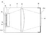
FIG. 1 is an explanatory view showing an example of the configuration of the light irradiation apparatus for photodynamic therapy of the present invention, and FIG. 2 is an explanatory view showing the configuration of a light source section in the light irradiation apparatus for photodynamic therapy of FIG. It is. Moreover, FIG. 3 is explanatory drawing which shows the arrangement state of the LED element in the light source part of FIG.
The
As the bioadministered substance, a compound which reacts in the living body as needed and is accumulated as a porphyrin compound in a lesion site is used.
Specific examples of the biologically administered substance include, for example, δ-aminolevulinic acid (5-ALA). As described above, this δ-aminolevulinic acid is a precursor of a photosensitizer, andprotoporphyrin IX (PpIX) synthesized via an enzyme reaction functions as a photosensitizer.
光線力学的治療用光照射装置10は、第1のLED素子22および第2のLED素子23を有する光源部20と、光源部20を構成する第1のLED素子22および第2のLED素子23の出力を制御する制御部30とを備え、光源部20および制御部30が支持体11によって支持されたものである。支持体11は、床面上において車輪18を介して支持される架台12を備え、この架台12の中央部において上方に伸びる支柱13の上部に、当該支柱13に対して光源部20を揺動自在に支持する作動アーム14が設けられたものである。支持体11において、光源部20は、作動アーム14の先端部に取り付けられており、一方、制御部30は、固定部材(図示省略)によって支柱13の中央部に取り付けられている。
図の例において、光源部20には、当該光源部20を手動によって揺動させるための手動レバー19が設けられている。The
In the example of the figure, the
光源部20は、2種類のLED素子、具体的には、波長400〜420nmの範囲にピーク波長を有する第1のLED素子22と、波長500〜520nmの範囲にピーク波長を有する第2のLED素子23とを有するものである。そして、この光源部20においては、第1のLED素子22と第2のLED素子23とが共に点灯されることによって、第1のLED素子22からの光(具体的には、波長400〜420nmの範囲にピーク波長を有する光)と、第2のLED素子23からの光(具体的には、波長500〜520nmの範囲にピーク波長を有する光)とが同時に放射される。
また、光源部20は、図2および図3に示すように、複数の第1のLED素子22と、複数の第2のLED素子23とを有するものであることが好ましい。
具体的に、光源部20は、図3に示すように、矩形筒状の枠体25の内部において、複数の第1のLED素子22と複数の第2のLED素子23とが、矩形状の基板24上に、当該基板24の外周縁に沿って縦横に並ぶよう配置されてなるLED素子ユニット21を備えている。
そして、LED素子ユニット21は、一方に開口27Aを有する直方体状の光源部用筐体27の内部において、支持部材(図示省略)によって支持されて、当該開口27Aに対向するように配置されている。このLED素子ユニット21には、当該LED素子ユニット21を構成する第1のLED素子22および第2のLED素子23に電力を供給するためのケーブル21Aが電気的に接続されている。このケーブル21Aにより、光源部20(LED素子ユニット21)と制御部30とが電気的に接続されている。また、光源部用筐体27の内部においては、LED素子ユニット21と開口27Aとの間に、LED素子ユニット21からの光(具体的には、第1のLED素子22からの光および第2のLED素子23からの光)を集光して混合するためのレンズ26が配置されており、またレンズ26と開口27Aとの間における、開口27Aに近接した位置には、所定の大きさに設定されたアパーチャー29が設けられている。また、光源部用筐体27には、開口27Aを閉塞するように窓部材28が設けられている。そして、開口27A、アパーチャー29および窓部材28によって光源部20の光出射部が構成されている。
このようにして、光源部20は、2つの異なる光、具体的には波長400〜420nmの範囲にピーク波長を有する光(第1のLED素子22からの光)と、波長500〜520nmの範囲にピーク波長を有する光(LED素子23からの光)とを、レンズ26により集光しつつ混合し、光出射部から放射する構成のものとされている。すなわち、光線力学的治療用光照射装置10においては、同一の照射部位に対して、光源部20から放射された、複数の第1のLED素子22からの光と複数の第2のLED素子23からの光とが同時に照射される。
この図の例において、照射面(照射部位)における照射領域は四角形状であって、当該照射領域の大きさの目安は縦寸法および横寸法が100mmである。
また、図3においては、第1のLED素子22が薄墨を施すことによって示されており、第2のLED素子23が濃墨を施すことによって示されている。The
Further, as shown in FIGS. 2 and 3, the
Specifically, as shown in FIG. 3, in the
The
Thus, the
In the example of this figure, the irradiation area | region in an irradiation surface (irradiation site | part) is a square shape, and the standard of the magnitude | size of the said irradiation area | region is 100 mm of a vertical dimension and a horizontal dimension.
Further, in FIG. 3, the
LED素子ユニット21において、当該LED素子ユニット21を構成する第1のLED素子22および第2のLED素子23の個数は、各々100個程度とされる。
そして、LED素子ユニット21においては、第2のLED素子23の個数が、第1のLED素子22の個数と同数またはそれ以上であることが好ましい。
第2のLED素子23の個数が第1のLED素子22の個数以上であることにより、光源部20からの光において、第1のLED素子22からの光(波長400〜420nmの範囲にピーク波長を有する光)のエネルギーの大きさ、および第2のLED素子23からの光(波長500〜520nmの範囲にピーク波長を有する光)のエネルギーの大きさを、両者の関係における所期の範囲に容易に調整することができる。
この図の例において、第1のLED素子22の個数および第2のLED素子23の個数は、共に162個であって同数である。In the
In the
When the number of
In the example of this figure, the number of
また、LED素子ユニット21において、複数の第1のLED素子22と複数の第2のLED素子23とは、図3に示されているように、所定の大きさのピッチ(中心間距離)によって同一種のLED素子同士が互いに隣接することのないように交互に格子状に配置されていることが好ましい。
第1のLED素子22と第2のLED素子23とが交互に格子状に配置されていることにより、照射面における照度分布に高い均一性が得られる。従って、実際の照射面の位置が、光源部20の光軸上において、設計中心値(設計上の照射面の位置)から前後にずれた場合であっても、その位置ずれに起因して、当該照射面(実際の照射面)における、第1のLED素子22からの光と第2のLED素子23からの光との混合度合いが低下することがない。
この図の例において、162個の第1のLED素子22と162個の第2のLED素子23とは、基板24上において、等間隔で交互に格子状(縦18行横18行)に配列されている。Further, in the
By arranging the
In the example of this figure, the 162
第1のLED素子22としては、青色LED素子などが用いられる。
この図の例において、第1のLED素子22としては、波長405nmにピーク波長を有する青色LED素子が用いられており、その青色LED素子には、表面を覆うように、透明性樹脂よりなる半球状のレンズ層が設けられている。As the
In the example of this figure, a blue LED element having a peak wavelength of 405 nm is used as the
第2のLED素子23としては、緑色LED素子などが用いられる。
この図の例において、第2のLED素子23としては、波長505nmにピーク波長を有する緑色LED素子が用いられており、その緑色LED素子には、表面を覆うように、透明性樹脂よりなる半球状のレンズ層が設けられている。A green LED element or the like is used as the
In the example of this figure, a green LED element having a peak wavelength of 505 nm is used as the
レンズ26としては、凸レンズおよびフレネルレンズなどを用いることができる。
レンズ26としてフレネルレンズを用いた場合には、レンズ26として凸レンズを用いた場合に比して光源部20を小型化することができることから、光線力学的治療用光照射装置10の小型化を図ることができる。
図の例において、レンズ26としては、凸レンズが用いられている。As the
When a Fresnel lens is used as the
In the illustrated example, a convex lens is used as the
窓部材28としては、LED素子ユニット21から出射される光(具体的には、第1のLED素子22からの光および第2のLED素子23からの光)に対する光透過性を有すると共に、高い機械的強度を有するものが用いられる。
窓部材28の材質の具体例としては、例えば石英ガラスなどが挙げられる。The
Specific examples of the material of the
アパーチャー29は、開口27Aと同等または開口27A以下の大きさを有するものとされている。
光源部20にアパーチャー29が設けられていることにより、照射面において照射領域と非照射領域との境界を明確にすることができ、よって意図しない部分、すなわち照射部位以外の部分に対する光照射(低出力露光)を防止することができる。The
By providing the
制御部30は、光源部20を構成するLED素子(具体的には、第1のLED素子22および第2のLED素子23)の出力を制御するものである。
制御部30によって光源部20を構成するLED素子の出力を制御することにより、光源部20において、疾患部位などに応じた所期の光を放射させることができる。
具体的に説明すると、例えば顔面、特に目の周辺部の腫瘍性病変(具体的には、例えば日光角化症等)の治療においては、高照度の光が照射されることに起因して、適宜の遮光を行っていても視界に光の残像が残り、十分な治療満足度が得られないおそれがある、という問題がある。而して、制御部30によって光源部20を構成するLED素子の出力を下げることにより、そのような問題に対処することができる。The
By controlling the output of the LED element constituting the
Specifically, for example, in the treatment of a neoplastic lesion on the face, particularly in the periphery of the eye (specifically, for example, actinic keratosis etc.), due to the irradiation of high-intensity light, There is a problem that an afterimage of light remains in the field of view even when appropriate shielding is performed, and a sufficient degree of treatment satisfaction can not be obtained. Such a problem can be dealt with by lowering the output of the LED element constituting the
また、制御部30は、第1のLED素子22の出力と第2のLED素子23の出力とを別個に制御できるものであることが好ましい。
制御部30が第1のLED素子22と第2のLED素子23との出力制御を別個に行うものであることにより、光源部20において、疾患の種類などに応じた所期の光を放射させることができる。具体的には、例えば、尋常性ざ瘡などのように病変部が皮膚表層に存在する場合には、第1のLED素子22からの波長400〜420nmの範囲にピーク波長を有する光の出力が高くなるように制御することにより、より高い治療効果が得られる。また、日光角化症、ボーエン病などのように病変部が生体内における比較的深い位置に存在する場合には、波長500〜520nmの範囲にピーク波長を有する光の出力が高くなるように制御することにより、より高い治療効果が得られる。In addition, it is preferable that the
Since the
そして、制御部30においては、光源部20からの光における、波長500〜520nmの範囲にピーク波長を有する光(第2のLED素子23からの光)のエネルギーの大きさが、波長400〜420nmの範囲にピーク波長を有する光(第1のLED素子22からの光)のエネルギーの大きさと同等以上の大きさとされることが好ましい。And in the
また、光源部20からの光において、第1のLED素子22からの光のエネルギー、および第2のLED素子23からの光のエネルギーは、疾患の種類、病変部の状態および治療時間(照射時間)などによって適宜に定められるが、具体的には、10mW/cm2以上であることが好ましく、更に好ましくは10〜60mW/cm2である。In the light from the
また、制御部30には、パルス幅変調制御または振幅可変制御によって光源部20からの光、具体的には、第1のLED素子22からの光(波長400〜420nmの範囲にピーク波長を有する光)および第2のLED素子23からの光(波長500〜520nmの範囲にピーク波長を有する光)のエネルギーの調整を行う照射エネルギー調整機構が設けられていることが好ましい。すなわち、制御部30においては、光源部20を構成するLED素子の出力を制御するための手段として、パルス幅変調制御による照射エネルギー調整機構または振幅可変制御による照射エネルギー調整機構が設けられていることが好ましい。この照射エネルギー調整機構は、第1のLED素子22と第2のLED素子23との出力制御を、例えば一方のLED素子の出力を100%とし、他方のLED素子の出力を70%とするように、別個に行うためには、各LED素子からの光のエネルギーの調整を別個に行うことのできるものとされる。
パルス幅変調制御による照射エネルギー調整機構においては、図4(a−1)〜(a−3)に示すように、光源部20を構成するLED素子を高速でパルス点灯させ、パルス波のデューティー比を制御すること、および図4(a−4)に示すように、光源部20を構成するLED素子をパルス点灯させないことにより、光源部20からの光のエネルギーの調整が行われる。
また、振幅可変制御による照射エネルギー調整機構においては、図4(b−1)〜(b−3)に示すように、光源部20を構成するLED素子に供給する電流を変化させること、および図4(b−4)に示すように、光源部20を構成するLED素子に供給する電流を変化さないことにより、光源部20からの光のエネルギーの調整が行われる。
図4において、(a−1)〜(a−4)および(b−1)〜(b−4)は、制御部30からの出力信号(LED素子の駆動信号)を示す説明図であり、(a−1)〜(a−3)においては、パルス変調制御を行うための出力信号を実線で示し、パルス変調制御を行わない場合における出力信号を破線で示している。具体的には、図4(a−1)における実線はデューティー比が10%のパルス幅変調制御を行うための出力信号を示し、図4(a−2)における実線はデューティー比が50%のパルス幅変調制御を行うための出力信号を示し、図4(a−3)における実線はデューティー比が90%のパルス幅変調制御を行うための出力信号を示す。同図(a−1)〜(a−3)において、Tは、パルス波の周期を示し、t(on)は、パルス幅変調におけるオン時間を示し、t(off)は、パルス幅変調におけるオフ時間を示す。また、図4における(b−1)〜(b−3)においては、振幅可変制御を行うための出力信号を実線で示し、制御を行わない場合における出力信号を破線で示している。具体的には、図4(b−1)における実線は振幅が10%の振幅可変制御を行うための出力信号を示し、図4(b−2)における実線は振幅が50%の振幅可変制御を行うための出力信号を示し、図4(b−3)における実線は振幅が90%の振幅可変制御を行うための出力信号を示す。また、図4における(a−4)および(b−4)は、いずれも、制御を行わない場合における出力信号を示す。The
In the irradiation energy adjusting mechanism by pulse width modulation control, as shown in FIG. 4 (a-1) to (a-3), the LED elements constituting the
Further, in the irradiation energy adjusting mechanism by the amplitude variable control, as shown in FIGS. 4 (b-1) to (b-3), changing the current supplied to the LED elements constituting the
In FIG. 4, (a-1) to (a-4) and (b-1) to (b-4) are explanatory diagrams showing output signals (drive signals of LED elements) from the
振幅可変制御による照射エネルギー調整機構は、例えば振幅制御電源などによって構成される。
また、パルス幅変調制御による照射エネルギー調整機構は、例えばパルス変調制御電源などによって構成される。The irradiation energy adjustment mechanism by the amplitude variable control is configured of, for example, an amplitude control power supply.
In addition, the irradiation energy adjustment mechanism by pulse width modulation control is configured by, for example, a pulse modulation control power supply.
そして、パルス幅変調制御による照射エネルギー調整機構によって光源部20からの光(具体的には、第1のLED素子22からの光および第2のLED素子23からの光)のエネルギーの調整を行う場合においては、パルス幅変調におけるオフ時間(t(off))が4μs以下であることが好ましい。なお、照射エネルギー調整機構によって第1のLED素子22からの光と第2のLED素子23からの光とがパルス幅変調制御される場合においては、それぞれの光に係るパルス幅変調におけるオフ時間は、4μs以下であれば異なっていてもよい。
パルス幅変調におけるオフ時間が4μs以下であることにより、パルス照射の影響、具体的には消光作用が生じることに起因して治療効果が低下するという弊害が生じることなく、振幅可変制御を行って連続照射を行った場合と同等の優れた治療効果が得られる。
ここに、パルス幅変調制御による照射エネルギー調整機構を、周波数125kHzのパルス変調制御電源によって構成した場合には、デューティー比が50%以下となるようにパルス幅変調制御を行うことにより、パルス幅変調におけるオフ時間(t(off))を4μs以下とすることができる。Then, the energy of the light from the light source unit 20 (specifically, the light from the
When the off-time in pulse width modulation is 4 μs or less, variable amplitude control is performed without the adverse effect that the therapeutic effect is reduced due to the influence of pulse irradiation, specifically the occurrence of the quenching action. The same excellent therapeutic effect as continuous irradiation can be obtained.
Here, when the irradiation energy adjustment mechanism by pulse width modulation control is configured by a pulse modulation control power supply with a frequency of 125 kHz, pulse width modulation control is performed by performing pulse width modulation control so that the duty ratio is 50% or less. The off time (t (off)) at the time t can be 4 μs or less.
制御部30は、直方体状の制御部用筐体37の内部に、LED駆動用電源ユニット、PLCなどの制御ユニットおよび照射エネルギー調整機構(具体的には、例えばパルス変調制御電源)が配設されており、また制御部用筐体37の側面に、グラフィック操作パネル39が配設されてなるものである。In the
このような光線力学的治療用光照射装置10は、光源部20が、窓部材28が照射部位と対向するようにして、当該照射部位から離間して配置される。ここに、照射部位と光源部20(窓部材28)との離間距離は、衛生面および照射像端のぼやけ防止の観点から、10〜50mmであることが好ましく、例えば20mmとされる。そして、制御部30から複数の第1のLED素子22および複数の第2のLED素子23の各々に電力を供給することによってこれらのLED素子が一斉に点灯され、同一の照射部位に対して、2つの異なる光、具体的には複数の第1のLED素子22からの光(波長400〜420nmの範囲にピーク波長を有する光)と複数の第2のLED素子23からの光(波長500〜520nmの範囲にピーク波長を有する光)とが、混合された状態で同時に照射される。Such photodynamic therapy
而して、光線力学的治療用光照射装置10は、同一の照射部位に対して、波長400〜420nmの範囲にピーク波長を有する光と波長500〜520nmの範囲にピーク波長を有する光とを組み合わせて照射するものであることから、後述の実験例(具体的には、実験例1)から明らかなように、これらの2つの異なる光を組み合わせることによる相乗効果が得られて、PDTによる治療の効率化が発揮される。そのため、2つの異なる光(具体的には、波長400〜420nmの範囲にピーク波長を有する光および波長500〜520nmの範囲にピーク波長を有する光)を単独波長照射した場合に比して、治療に必要とされる照射量(積算光量)を少なくすることができる。その結果、治療に要する照射時間の短縮化を図ることができる。
従って、光線力学的治療用光照射装置10によれば、短時間の光照射によって優れた治療効果を得ることができる。
ここに、波長400〜420nmの範囲にピーク波長を有する光と波長500〜520nmの範囲にピーク波長を有する光とを組み合わせることによって相乗効果が得られる理由は、以下のように推測される。
波長400〜420nmの範囲にピーク波長を有する光および波長500〜520nmの範囲にピーク波長を有する光のうちの一方の光によって光増感性物質が光変性され、当該2つの異なる光のうちの他方の光に大きな吸収ピークを有するものとなる。そして、一方の光によって光変性された光変性物質が、他方の光によって更に光変性されこととなる。このようにして、2つの異なる光を組み合わせることによる相乗効果が得られると推測される。Thus, the
Therefore, according to the
Here, the reason why a synergistic effect can be obtained by combining light having a peak wavelength in the wavelength range of 400 to 420 nm and light having a peak wavelength in the range of 500 to 520 nm is presumed as follows.
The photosensitizer is photomodified by one of light having a peak wavelength in the wavelength range of 400 to 420 nm and light having a peak wavelength in the range of 500 to 520 nm, and the other of the two different types of light Light has a large absorption peak. Then, the photo-denatured substance photo-denatured by one light is further photo-denatured by the other light. In this way, it is assumed that a synergetic effect can be obtained by combining two different lights.
また、光線力学的治療用光照射装置10においては、後述の実験例(具体的には、実験例2)から明らかなように、制御部30をパルス幅変調制御による照射エネルギー調整機構を有するものとする場合において、パルス幅変調におけるオフ時間を4μs以下とすることにより、振幅可変制御を行って連続照射を行った場合と同等の優れた治療効果を得ることができる。すなわち、光線力学的治療用光照射装置10において、低コストで流通性もよいことから工業用途において広く利用されているパルス幅変調制御を適用する場合には、パルス幅変調におけるオフ時間を4μs以下とすることにより、パルス照射の影響(消光作用)によって治療効果が低下するという弊害が生じることを防止できる。Further, in photodynamic therapy light irradiation device 10 (specifically, Experimental Example 2) Experimental Example below As it is clear from,those having an irradiation energy adjustment
本発明においては、上記の実施の形態に限定されず、種々の変更を加えることが可能である。
例えば、光線力学的治療用光照射装置は、第1のLED素子と第2のLED素子とを共に点灯させることのできるものであれば、装置利用性の観点から、第1のLED素子および第2のLED素子のうちの一方のみを選択的に点灯することのできるものであってもよい。In the present invention, various modifications can be made without being limited to the above embodiment.
For example, as long as the light irradiation device for photodynamic therapy can turn on both the first LED element and the second LED element, the first LED element and the second LED element can be used from the viewpoint of device availability. only selectivelyit may be one that can be turned one of the two LED elements.
また、光源部は、図5に示すように、第1のLED素子22からの光と第2のLED素子23からの光とを混合するための光混合部材として拡散板41が設けられたものであってもよい。このような構成の光源部20を備えた光線力学的治療用光照射装置においては、図5に示されているように、拡散板41を、LED素子ユニット21に近接して配設することができる。具体的に、図5においては、拡散板41は、枠体25の開口を塞ぐように配設されている。そのため、図2に示したように光混合部材としてレンズを用いた場合のように、LED素子ユニット21と光源部用筐体27の開口27Aとの間に大きな離間距離が必要とされることがない。その結果、光源部20を小型化することができることから、光線力学的治療用光照射装置自体の小型化を図ることができる。
このような光線力学的治療用光照射装置は、光混合部材としてレンズが設けられたものに比して、放射照度が30%程度低下することから、尋常性ざ瘡などのように必要とされる光照射量が低い疾患の治療に好適に用いられる。
すなわち、光源部は、照射面において高照度を得るためには、図2に示されるように第1のLED素子からの光と第2のLED素子からの光とを混合するための光混合部材として集光機能を有するレンズが設けられたものであることが好ましい。しかしながら、病変部において必要とされる照射量が比較的低い疾患の治療に用いられる光線力学的治療用光照射装置においては、第1のLED素子および第2のLED素子として高出力のものを用いることにより、光混合部材として拡散板を好適に用いることができる。Further, as shown in FIG. 5, the light source unit is provided with a
Such a light irradiation device for photodynamic treatment is required as in acne vulgaris because the irradiance is reduced by about 30% as compared with a device provided with a lens as a light mixing member. Is suitably used for the treatment of diseases with a low light dose.
That is, the light source unit is a light mixing member for mixing the light from the first LED element and the light from the second LED element as shown in FIG. Preferably, a lens having a light collecting function is provided. However, in the light irradiation apparatus for photodynamic therapy used for treatment of a disease having a relatively low radiation dose required at a lesion site, high-output ones are used as the first LED element and the second LED element. Thus, a diffusion plate can be suitably used as thelight mixing member .
また、光源部は、LED素子ユニットに、第1のLED素子および第2のLED素子と共に、その他のLED素子、具体的には、ピーク波長が635nmの赤色LED素子が配設されたものであってもよい。このような構成の光源部を備えた光線力学的治療用光照射装置によれば、赤色LED素子のみを選択的に点灯することのできるものとすることにより、赤色光照射器としても利用することができることから、装置の利用性が大きくなる。 In the light source unit, the LED element unit is provided with the first LED element and the second LED element, and other LED elements, specifically, a red LED element having a peak wavelength of 635 nm. May be According to the light irradiation apparatus for photodynamic treatment provided with the light source unit having such a configuration, it is possible to selectively turn on only the red LED element, thereby utilizing it as a red light irradiator. Availability of the device increases.
以下、本発明の実験例について説明する。 Hereinafter, experimental examples of the present invention will be described.
〔実験例1〕
複数のプレート内において、HaCaT細胞(ヒト皮膚角化細胞株)1×105個を18時間かけて培養した後、PBS(リン酸緩衝生理食塩水)によって希釈した、濃度1mMのδ−アミノレブリン酸(5-ALA)溶液200μlを添加した。そして、4時間経過後に、1つのプレート以外の複数のプレートに対して、各々、照射量が0.2J/cm2、0.4J/cm2、0.6J/cm2、0.8J/cm2、1.0J/cm2および1.2J/cm2となる条件により、5種の単独波長照射、および4種の複数波長照射(具体的には、2波長照射)を行った。具体的に、5種の単独波長照射としては、波長405nmの光、波長505nmの光、波長545nmの光、波長570nmの光、および波長635nmの光の照射を行った。また、4種の複数波長照射としては、波長405nmの光と波長505nmの光とを組み合わせた光、波長405nmの光と波長545nmの光とを組み合わせた光、波長405nmの光と波長570nmの光とを組み合わせた光、および波長405nmの光と波長635nmの光とを組み合わせた光の照射を行った。これらの単独波長照射および複数波長照射において、波長405nmの光の光源としては、当該光源からの光のエネルギーが11mW/cm2(照射距離100mm)であるLED素子を用いた。また、波長505nmの光の光源としては、当該光源からの光のエネルギーが17mW/cm2(照射距離40mm)であるLED素子を用いた。
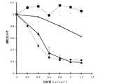
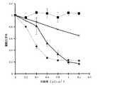
その後、光照射を行った複数のプレートおよび光照射を行わなかったプレートにおいて18時間にわたって培養を行い、XTT細胞増殖アッセイキッドを用いたMTT試験によって細胞生存率を測定した。結果を図6〜図9に示す。この図6〜図9においては、光照射を行わなかったプレートにおける細胞生存率を基準とした細胞生存率の相対値が示されている。
また、光照射量が0.4J/cm2である場合の細胞生存率の結果に基づいて、下記の数式(1)により、光線力学的治療法による治療効果(以下、「PDT効果」ともいう。)を算出した。結果を図10に示す。
図6には、波長405nmの光の単独波長照射に係る結果が菱形プロット(◆)、波長505nmの光の単独波長照射に係る結果が四角プロット(■)、および波長405nmの光と波長505nmの光とを組み合わせた複数波長照射に係る結果が三角プロット(▲)で示されている。
図7には、波長405nmの光の単独波長照射に係る結果が菱形プロット(◆)、波長545nmの光の単独波長照射に係る結果が四角プロット(■)、および波長405nmの光と波長545nmの光とを組み合わせた複数波長照射に係る結果が三角プロット(▲)で示されている。
図8には、波長405nmの光の単独波長照射に係る結果が菱形プロット(◆)、波長570nmの光の単独波長照射に係る結果が四角プロット(■)、および波長405nmの光と波長570nmの光とを組み合わせた複数波長照射に係る結果が三角プロット(▲)で示されている。
図9には、波長405nmの光の単独波長照射に係る結果が菱形プロット(◆)、波長635nmの光の単独波長照射に係る結果が四角プロット(■)、および波長405nmの光と波長635nmの光とを組み合わせた複数波長照射に係る結果が三角プロット(▲)で示されている。
また、図6〜図9においては、2種の単独波長照射に係る結果に基づいて算出された細胞生存率基準値がクロスプロット(×)で示されており、またそのクロスプロットに基づく基準ラインが示されている。ここに、細胞生存率基準値は、複数波長照射における照射量をI〔J/cm2〕としたときの、当該複数波長照射における一方の波長の光の単独波長照射の照射量I/2〔J/cm2〕に係る細胞生存率をE1、当該複数波長照射における他方の波長の光の単独波長照射の照射量I/2〔J/cm2〕に係る細胞生存率をE2とするとき、下記の数式(2)を用いて算出された値である。
図10においては、波長405nmの光と波長505nmの光とを組み合わせた複数波長照射に係るPDT効果が「405+505」として示されており、波長405nmの光と波長545nmの光とを組み合わせた複数波長照射に係るPDT効果が「405+545」として示されており、波長405nmの光と波長570nmの光とを組み合わせた複数波長照射に係るPDT効果が「405+570」として示されており、および波長405nmの光と波長635nmの光とを組み合わせた複数波長照射に係るPDT効果が「405+635」として示されている。[Experimental Example 1]
After culturing 1 × 10⁵ HaCaT cells (human skin keratinocyte cell line) for 18 hours in multiple plates, it was diluted with PBS (phosphate buffered saline) to a concentration of 1 mM δ-aminolevulinic acid 200 μl of (5-ALA) solution were added. Then, after 4 hours, the irradiation dose is 0.2 J / cm2 , 0.4 J / cm2 , 0.6 J / cm2 , 0.8 J / cm for each of a plurality of plates other than one plate.2, the condition to be 1.0 J / cm2 and 1.2 J / cm2, 5 kinds of single wavelength radiation, and (specifically, two-wavelength radiation) four of a plurality of wavelengths irradiated was. Specifically, as five types of single wavelength irradiation, irradiation with light of
Thereafter, the cells were cultured for 18 hours in a plurality of plates irradiated with light and a plate not irradiated with light, and cell viability was measured by MTT test using XTT cell proliferation assay kit. The results are shown in FIGS. In FIGS. 6 to 9, relative values of cell viability based on cell viability in a plate not subjected to light irradiation are shown.
In addition, based on the result of cell survival rate when the light irradiation dose is 0.4 J / cm2 , the therapeutic effect by photodynamic therapy (hereinafter also referred to as “PDT effect”) according to the following formula (1) ) Was calculated. The results are shown in FIG.
In FIG. 6, the results relating to single wavelength irradiation of light of
In FIG. 7, the results relating to single wavelength irradiation of light of
In FIG. 8, the results relating to single wavelength irradiation of light having a wavelength of 405 nm are rhombic plot (、), the results relating to single wavelength irradiation of light having a wavelength of 570 nm are square plot (■), and the light having a wavelength of 405 nm and 570 nm The results for multiple wavelength illumination combined with light are shown in the triangular plot (▲).
In FIG. 9, the results relating to single wavelength irradiation of light having a wavelength of 405 nm are rhombic plot (、), the results relating to single wavelength irradiation of light having a wavelength of 635 nm are square plot (プ ロ ッ ト), and the light having a wavelength of 405 nm and 635 nm The results for multiple wavelength illumination combined with light are shown in the triangular plot (▲).
Moreover, in FIGS. 6-9, the cell viability reference value calculated based on the result which concerns on two types of single wavelength irradiation is shown by the cross plot (x), and the reference line based on the cross plot. It is shown. Here, the cell viability reference value is the irradiation dose I / 2 of single wavelength irradiation of light of one wavelength in the multiple wavelength irradiation, where the irradiation dose in multiple wavelength irradiation is I [J / cm2 ]. Assuming that the cell viability relating to J / cm2 ] is
In FIG. 10, the PDT effect concerning multiple wavelength irradiation which combined light of
数式(1):
PDT効果=1−(細胞生存率)Formula (1):
PDT effect = 1-(cell survival rate)
数式(2):
細胞生存率基準値=(E1+E2)/2Equation (2):
Cell viability reference value = (E1 + E2) / 2
この実験例1の結果から、プロトポルフィリンIX(PpIX)における5つの吸収ピーク(具体的には、波長410nm、波長510nm、波長545nm、波長580nmおよび波長630nm)に相当する5つの光(具体的には、波長405nmの光、波長505nmの光、波長545nmの光、波長570nmの光および波長635nmの光)のうちでは、波長405nmの光が最も優れたPDT効果が得られることが明らかとなった。
そして、波長405nmの光と波長505nmの光とを組み合わせることにより、相乗効果が得られ、0.4J/cm2という低い照射量であっても、優れたPDT効果が得られることが明らかとなった。
一方、波長405nmの光と、波長545nmの光、波長570nmの光または波長635nmの光との組み合わせにおいては、いずれの組み合わせにおいても、照射量が0.4J/cm2と低い場合には、相乗効果が得られず、十分なPDT効果が得られないことが明らかとなった。
具体的に説明すると、波長405nmの光と波長545nmの光とを組み合わせた場合、および波長405nmの光と波長635nmの光とを組み合わせた場合においては、0.9J/cm2以上の照射量では相乗効果が得られるものの、0.4J/cm2という低い照射量では相乗効果が得られないことが明らかとなった。また、波長405nmの光と波長570nmの光との組み合わせにおいては、相乗効果が全く得られないことが明らかとなった。
従って、本発明の光線力学的治療用光照射装置によれば、短時間の光照射によって優れた治療効果が得られることが確認された。From the results of this Experimental Example 1, five light peaks (specifically, specifically, light having a wavelength of 410 nm, a wavelength of 510 nm, a wavelength of 545 nm, a wavelength of 580 nm and a wavelength of 630 nm) inprotoporphyrin IX (PpIX) Among the light with a wavelength of 405 nm, the light with a wavelength of 505 nm, the light with a wavelength of 545 nm, the light with a wavelength of 570 nm and the light with a wavelength of 635 nm), it became clear that the light with a wavelength of 405 nm provides the best PDT effect. .
Then, by combining the light of
On the other hand, in the combination of light with a wavelength of 405 nm, light with a wavelength of 545 nm, light with a wavelength of 570 nm or light with a wavelength of 635 nm, synergy is obtained when the irradiation amount is as low as 0.4 J / cm2 in any combination. It became clear that the effect was not obtained and sufficient PDT effect was not obtained.
Specifically, when the light of
Therefore, according to the light irradiation apparatus for photodynamic treatment of the present invention, it was confirmed that excellent treatment effect can be obtained by light irradiation for a short time.
〔実験例2〕
複数のプレート内において、HaCaT細胞(ヒト皮膚角化細胞株)1×105個をプレートに18時間かけて培養した後、PBS(リン酸緩衝生理食塩水)によって希釈した、濃度1mMのδ−アミノレブリン酸(5-ALA)溶液200μlを添加した。そして、4時間経過後に、1つのプレート以外の複数のプレートに対して、各々、図11に示すようなパルス幅変調による256階調の調光ができる、周波数125kHzのパルス変調制御電源(PWM電源)を用い、表1に従って、照射量が12J/cm2となる条件(1)〜条件(6)により、波長635nmの光を照射した。具体的に、条件(1)においては、パルス幅変調におけるオフ時間(t(off))が5.6μsのパルス変調制御による光の照射を行い、条件(2)においては、パルス幅変調におけるオフ時間(t(off))が5.3μsのパルス変調制御による光の照射を行い、条件(3)においては、パルス幅変調におけるオフ時間(t(off))が4.8μsのパルス変調制御による光の照射を行い、条件(4)においては、パルス幅変調におけるオフ時間(t(off))が4.0μsのパルス変調制御による光の照射を行い、条件(5)においては、パルス幅変調におけるオフ時間(t(off))が2.7μsのパルス変調制御による光の照射を行った。条件(1)〜条件(5)においては、いずれにおいても、パルス周期(T)は8μsである。また、条件(6)においては、パルス幅変調におけるオフ時間(t(off))が0μsの光の照射、すなわち連続照射であって振幅可変制御と同等の条件による光の照射を行った。
その後、光照射を行った複数のプレートおよび光照射を行わなかったプレートにおいて18時間にわたって培養を行い、XTT細胞増殖アッセイキッドを用いたMTT試験によって細胞生存率を測定した。結果を図12に示す。この図12においては、光照射を行わなかったプレートにおける細胞生存率を基準とした細胞生存率の相対値が示されている。
[Experimental Example 2]
After 1 × 10⁵ HaCaT cells (human skin keratinocyte cell line) were cultured on the plate for 18 hours in multiple plates, 1 mM δ − was diluted with PBS (phosphate buffered saline). 200 μl of aminolevulinic acid (5-ALA) solution was added. Then, after 4 hours have elapsed, a pulse modulation control power supply (PWM power supply with a frequency of 125 kHz that can perform dimming of 256 gradations by pulse width modulation as shown in FIG. 11 for multiple plates other than one plate) The light having a wavelength of 635 nm was irradiated under conditions (1) to (6) in which the irradiation amount was 12 J / cm2 according to Table 1). Specifically, in the condition (1), light is emitted by pulse modulation control with an off time (t (off)) of 5.6 μs in pulse width modulation, and in the condition (2), the light in pulse width modulation is turned off The light is irradiated by pulse modulation control with a time (t (off) of 5.3 μs, and under the condition (3), the pulse modulation control is performed with an off time (t (off)) of 4.8 μs in pulse width modulation. Irradiation of light is performed, and in condition (4), light irradiation is performed by pulse modulation control with an off time (t (off)) of 4.0 μs in pulse width modulation, and in condition (5), pulse width modulation is performed The light irradiation was performed by pulse modulation control at an off time (t (off)) at 2.7 μs. In each of the conditions (1) to (5), the pulse period (T) is 8μs . Further, under the condition (6), irradiation with light with an off time (t (off)) of 0 μs in pulse width modulation, that is, continuous irradiation, was performed under the same conditions as the variable amplitude control.
Thereafter, the cells were cultured for 18 hours in a plurality of plates irradiated with light and a plate not irradiated with light, and cell viability was measured by MTT test using XTT cell proliferation assay kit. The results are shown in FIG. In FIG. 12, the relative value of the cell viability based on the cell viability in the plate not subjected to the light irradiation is shown.

この実験例2の結果から、周波数125kHzのパルス変調制御電源を用いて、デューティー比を50%以下としてパルス幅変調におけるオフ時間(t(off))が4μs以下となるようにパルス幅変調制御を行うことにより、振幅可変制御を行って連続照射を行った場合と同等のPDT効果が得られることが明らかである。
従って、本発明の光線力学的治療用光照射装置を用いたPDTにおいて、パルス幅変調制御を行ってパルス照射をする場合には、パルス幅変調におけるオフ時間を4μs以下とすることにより、振幅可変制御を行って連続照射を行った場合と同等の優れた治療効果が得られることが確認された。From the result of this experimental example 2, using a pulse modulation control power supply with a frequency of 125 kHz, pulse width modulation control is performed so that the off time (t (off)) in pulse width modulation is 4 μs or less with a duty ratio of 50% or less. It is clear that, by performing this, the PDT effect equivalent to the case of performing continuous irradiation with the variable amplitude control can be obtained.
Therefore, in the PDT using the light irradiation apparatus for photodynamic therapy of the present invention, when pulse width modulation control is performed and pulse irradiation is performed, the amplitude can be varied by setting the off time in pulse width modulation to 4 μs or less. It was confirmed that the same excellent therapeutic effect as in the case of continuous irradiation with control was obtained.
10 光線力学的治療用光照射装置
11 支持体
12 架台
13 支柱
14 作動アーム
18 車輪
19 手動レバー
20 光源部
21 LED素子ユニット
21A ケーブル
22 第1のLED素子
23 第2のLED素子
24 基板
25 枠体
26 レンズ
27 光源部用筐体
27A 開口
28 窓部材
29 アパーチャー
30 制御部
37 制御部用筐体
39 グラフィック操作パネル
41 拡散板
DESCRIPTION OF
Claims (3)
Translated fromJapanese前記第1のLED素子および前記第2のLED素子の出力を制御する制御部と
を備え、
同一の照射部位に対して、前記光源部を構成する第1のLED素子および第2のLED素子が共に点灯されることによって当該第1のLED素子からの光と当該第2のLED素子からの光とが照射されることを特徴とする光線力学的治療用光照射装置。A light source unit havingonly two types of LED elements , a first LED element having a peak wavelength in the wavelength range of 400 to 420 nm and a second LED element having a peak wavelength in the range of 500 to 520 nm;
A controller configured to control the output of the first LED element and the second LED element;
The light from the first LED element and the light from the second LED element are emitted by lighting both the first LED element and the second LED element constituting the light source unit to the same irradiation site. A light irradiation device for photodynamic treatment, characterized in that it is irradiated with light.
Priority Applications (4)
| Application Number | Priority Date | Filing Date | Title |
|---|---|---|---|
| JP2015126336AJP6516219B2 (en) | 2015-06-24 | 2015-06-24 | Photodynamic therapy light irradiator |
| US15/737,398US20180193659A1 (en) | 2015-06-24 | 2016-03-25 | Photodynamic therapy light irradiating device and light irradiating method |
| CN201680036350.0ACN107708800A (en) | 2015-06-24 | 2016-03-25 | The treatment light irradiation device and light illuminating method of photodynamics |
| PCT/JP2016/059566WO2016208244A1 (en) | 2015-06-24 | 2016-03-25 | Photodynamic therapy light irradiating device and light irradiating method |
Applications Claiming Priority (1)
| Application Number | Priority Date | Filing Date | Title |
|---|---|---|---|
| JP2015126336AJP6516219B2 (en) | 2015-06-24 | 2015-06-24 | Photodynamic therapy light irradiator |
Publications (2)
| Publication Number | Publication Date |
|---|---|
| JP2017006454A JP2017006454A (en) | 2017-01-12 |
| JP6516219B2true JP6516219B2 (en) | 2019-05-22 |
Family
ID=57585027
Family Applications (1)
| Application Number | Title | Priority Date | Filing Date |
|---|---|---|---|
| JP2015126336AActiveJP6516219B2 (en) | 2015-06-24 | 2015-06-24 | Photodynamic therapy light irradiator |
Country Status (4)
| Country | Link |
|---|---|
| US (1) | US20180193659A1 (en) |
| JP (1) | JP6516219B2 (en) |
| CN (1) | CN107708800A (en) |
| WO (1) | WO2016208244A1 (en) |
Families Citing this family (10)
| Publication number | Priority date | Publication date | Assignee | Title |
|---|---|---|---|---|
| US20200179711A1 (en)* | 2017-06-20 | 2020-06-11 | Public University Corporation Nagoya City University | Photodynamic therapy light irradiation device |
| CN108744293B (en)* | 2018-05-29 | 2019-06-04 | 清华大学深圳研究生院 | A kind of Digital Optical device for image conversion corneal cross-linking |
| WO2020066577A1 (en)* | 2018-09-26 | 2020-04-02 | 国立大学法人大阪大学 | Therapeutic drug for periodontal disease |
| US20220314021A1 (en)* | 2019-02-19 | 2022-10-06 | Otsuka Electronics Co., Ltd. | Method for determining condition parameters for photodynamic therapy and photodynamic therapy apparatus |
| JP7176088B2 (en)* | 2019-02-25 | 2022-11-21 | 大塚電子株式会社 | Photodynamic therapy device |
| CN114222606A (en)* | 2019-06-05 | 2022-03-22 | 生物前沿制药有限公司 | Illumination for photodynamic therapy |
| CN110975160A (en)* | 2019-12-05 | 2020-04-10 | 李蕊 | Back dehumidifying device based on simulation sunbath for medical nursing |
| EP4103275A1 (en)* | 2020-02-12 | 2022-12-21 | JK-Holding GmbH | Body irradiating device |
| CN111588993B (en)* | 2020-05-22 | 2022-08-16 | 朱九华 | Medical automatic position-changing baking lamp |
| CN117908429A (en)* | 2023-12-11 | 2024-04-19 | 皖南医学院 | A complex light source control system for photodynamic therapy |
Family Cites Families (11)
| Publication number | Priority date | Publication date | Assignee | Title |
|---|---|---|---|---|
| US6887260B1 (en)* | 1998-11-30 | 2005-05-03 | Light Bioscience, Llc | Method and apparatus for acne treatment |
| GB2360459B (en)* | 2000-03-23 | 2002-08-07 | Photo Therapeutics Ltd | Therapeutic light source and method |
| JP4359103B2 (en)* | 2003-08-22 | 2009-11-04 | 合同会社希少糖生産技術研究所 | Cancer cell growth suppression apparatus provided with LED irradiation means in the presence of rare sugar |
| WO2006098719A1 (en)* | 2005-03-09 | 2006-09-21 | The Procter & Gamble Company | Sensor responsive electric toothbrushes and methods of use |
| JP2006289098A (en)* | 2005-04-12 | 2006-10-26 | Inolase 2002 Ltd | Apparatus for vacuum-assisted light-based treatment of skin |
| JP2008237618A (en)* | 2007-03-27 | 2008-10-09 | Toin Gakuen | Light irradiation device for photodynamical therapy |
| CN101612452B (en)* | 2008-06-24 | 2013-01-02 | 天津医科大学 | Photoirradiation head of photodynamic therapy apparatus |
| JP2010284399A (en)* | 2009-06-15 | 2010-12-24 | Yayoi:Kk | Photodynamic therapy device |
| US20140067024A1 (en)* | 2012-08-30 | 2014-03-06 | Photocure Asa | Dual panel photodynamic therapy lamp |
| US10328276B2 (en)* | 2014-02-14 | 2019-06-25 | Applied Biophotonics Ltd. | Sinusoidal drive system and method for phototherapy |
| JP6112416B2 (en)* | 2013-09-06 | 2017-04-12 | パナソニックIpマネジメント株式会社 | Light irradiation device for body hair |
- 2015
- 2015-06-24JPJP2015126336Apatent/JP6516219B2/enactiveActive
- 2016
- 2016-03-25CNCN201680036350.0Apatent/CN107708800A/enactivePending
- 2016-03-25USUS15/737,398patent/US20180193659A1/ennot_activeAbandoned
- 2016-03-25WOPCT/JP2016/059566patent/WO2016208244A1/ennot_activeCeased
Also Published As
| Publication number | Publication date |
|---|---|
| JP2017006454A (en) | 2017-01-12 |
| WO2016208244A1 (en) | 2016-12-29 |
| US20180193659A1 (en) | 2018-07-12 |
| CN107708800A (en) | 2018-02-16 |
Similar Documents
| Publication | Publication Date | Title |
|---|---|---|
| JP6516219B2 (en) | Photodynamic therapy light irradiator | |
| US6835202B2 (en) | Apparatus and method for high energy photodynamic therapy of acne vulgaris and seborrhea | |
| US20020128695A1 (en) | Apparatus and method for high energy photodynamic therapy of acne vulgaris and seborrhea | |
| US20020173833A1 (en) | Apparatus and method for high energy photodynamic therapy of acne vulgaris, seborrhea and other skin disorders | |
| KR101496370B1 (en) | Light emitting device for use in therapeutic and/or cosmetic treatment | |
| US6626932B2 (en) | Therapeutic light source and method | |
| US12186221B2 (en) | Blue light photobiomodulation | |
| CN103920248B (en) | A kind of synchronizable optical power therapentic equipment | |
| CA2205041A1 (en) | Light therapy treatment arrangement and use thereof | |
| JP6735995B2 (en) | Light irradiation device for photodynamic therapy | |
| US20150297915A1 (en) | Apparatus for maintaining treatment of peripheral neuropathy | |
| CN109675202B (en) | Photodynamic and ultrasonic atomization composite treatment device and treatment method | |
| Navarrete-de Gálvez et al. | Analysis and evaluation of the operational characteristics of a new photodynamic therapy device | |
| US7087074B2 (en) | Light therapy apparatus | |
| JP2004242790A (en) | Phototherapy apparatus | |
| US10279193B2 (en) | Space, luminous ceiling system and method for conducting photodynamic therapy | |
| WO2022035735A1 (en) | Phototherapy systems, methods of using a phototherapy system, and methods of manufacturing a phototherapy system | |
| WO2005035059A1 (en) | Portable illuminator for photodynamic diagnostics | |
| JP2006015051A (en) | Photo-therapy apparatus | |
| CN114010954B (en) | In-vivo photo-medical device | |
| KR20120030469A (en) | Medical treatment apparatus using rays of light | |
| Hernández-Quintanar et al. | Development of an irradiation system for photodynamic therapy with dosimetric control | |
| WO2005035058A1 (en) | Mobile device for photodynamic diagnostics and therapy and methods | |
| KR20020088832A (en) | Therapeutic light source and method using the same | |
| WO2025160272A1 (en) | Illumination device |
Legal Events
| Date | Code | Title | Description |
|---|---|---|---|
| A621 | Written request for application examination | Free format text:JAPANESE INTERMEDIATE CODE: A621 Effective date:20180227 | |
| A521 | Request for written amendment filed | Free format text:JAPANESE INTERMEDIATE CODE: A821 Effective date:20180227 | |
| A131 | Notification of reasons for refusal | Free format text:JAPANESE INTERMEDIATE CODE: A131 Effective date:20180814 | |
| A521 | Request for written amendment filed | Free format text:JAPANESE INTERMEDIATE CODE: A523 Effective date:20181003 | |
| RD03 | Notification of appointment of power of attorney | Free format text:JAPANESE INTERMEDIATE CODE: A7423 Effective date:20181003 | |
| TRDD | Decision of grant or rejection written | ||
| A01 | Written decision to grant a patent or to grant a registration (utility model) | Free format text:JAPANESE INTERMEDIATE CODE: A01 Effective date:20190312 | |
| A61 | First payment of annual fees (during grant procedure) | Free format text:JAPANESE INTERMEDIATE CODE: A61 Effective date:20190408 | |
| R150 | Certificate of patent or registration of utility model | Ref document number:6516219 Country of ref document:JP Free format text:JAPANESE INTERMEDIATE CODE: R150 | |
| R250 | Receipt of annual fees | Free format text:JAPANESE INTERMEDIATE CODE: R250 | |
| R250 | Receipt of annual fees | Free format text:JAPANESE INTERMEDIATE CODE: R250 | |
| R250 | Receipt of annual fees | Free format text:JAPANESE INTERMEDIATE CODE: R250 | |
| R250 | Receipt of annual fees | Free format text:JAPANESE INTERMEDIATE CODE: R250 |