JP6515898B2 - Target lane relation recognition device - Google Patents
Target lane relation recognition deviceDownload PDFInfo
- Publication number
- JP6515898B2 JP6515898B2JP2016190888AJP2016190888AJP6515898B2JP 6515898 B2JP6515898 B2JP 6515898B2JP 2016190888 AJP2016190888 AJP 2016190888AJP 2016190888 AJP2016190888 AJP 2016190888AJP 6515898 B2JP6515898 B2JP 6515898B2
- Authority
- JP
- Japan
- Prior art keywords
- lane
- target
- vehicle
- information
- recognition device
- Prior art date
- Legal status (The legal status is an assumption and is not a legal conclusion. Google has not performed a legal analysis and makes no representation as to the accuracy of the status listed.)
- Active
Links
Images


Classifications
- B—PERFORMING OPERATIONS; TRANSPORTING
- B60—VEHICLES IN GENERAL
- B60W—CONJOINT CONTROL OF VEHICLE SUB-UNITS OF DIFFERENT TYPE OR DIFFERENT FUNCTION; CONTROL SYSTEMS SPECIALLY ADAPTED FOR HYBRID VEHICLES; ROAD VEHICLE DRIVE CONTROL SYSTEMS FOR PURPOSES NOT RELATED TO THE CONTROL OF A PARTICULAR SUB-UNIT
- B60W30/00—Purposes of road vehicle drive control systems not related to the control of a particular sub-unit, e.g. of systems using conjoint control of vehicle sub-units
- B60W30/10—Path keeping
- B60W30/12—Lane keeping
- B—PERFORMING OPERATIONS; TRANSPORTING
- B60—VEHICLES IN GENERAL
- B60W—CONJOINT CONTROL OF VEHICLE SUB-UNITS OF DIFFERENT TYPE OR DIFFERENT FUNCTION; CONTROL SYSTEMS SPECIALLY ADAPTED FOR HYBRID VEHICLES; ROAD VEHICLE DRIVE CONTROL SYSTEMS FOR PURPOSES NOT RELATED TO THE CONTROL OF A PARTICULAR SUB-UNIT
- B60W30/00—Purposes of road vehicle drive control systems not related to the control of a particular sub-unit, e.g. of systems using conjoint control of vehicle sub-units
- B60W30/10—Path keeping
- B—PERFORMING OPERATIONS; TRANSPORTING
- B60—VEHICLES IN GENERAL
- B60W—CONJOINT CONTROL OF VEHICLE SUB-UNITS OF DIFFERENT TYPE OR DIFFERENT FUNCTION; CONTROL SYSTEMS SPECIALLY ADAPTED FOR HYBRID VEHICLES; ROAD VEHICLE DRIVE CONTROL SYSTEMS FOR PURPOSES NOT RELATED TO THE CONTROL OF A PARTICULAR SUB-UNIT
- B60W30/00—Purposes of road vehicle drive control systems not related to the control of a particular sub-unit, e.g. of systems using conjoint control of vehicle sub-units
- B60W30/18—Propelling the vehicle
- B60W30/18009—Propelling the vehicle related to particular drive situations
- B60W30/18163—Lane change; Overtaking manoeuvres
- B—PERFORMING OPERATIONS; TRANSPORTING
- B60—VEHICLES IN GENERAL
- B60W—CONJOINT CONTROL OF VEHICLE SUB-UNITS OF DIFFERENT TYPE OR DIFFERENT FUNCTION; CONTROL SYSTEMS SPECIALLY ADAPTED FOR HYBRID VEHICLES; ROAD VEHICLE DRIVE CONTROL SYSTEMS FOR PURPOSES NOT RELATED TO THE CONTROL OF A PARTICULAR SUB-UNIT
- B60W40/00—Estimation or calculation of non-directly measurable driving parameters for road vehicle drive control systems not related to the control of a particular sub unit, e.g. by using mathematical models
- B60W40/02—Estimation or calculation of non-directly measurable driving parameters for road vehicle drive control systems not related to the control of a particular sub unit, e.g. by using mathematical models related to ambient conditions
- B60W40/06—Road conditions
- G—PHYSICS
- G01—MEASURING; TESTING
- G01C—MEASURING DISTANCES, LEVELS OR BEARINGS; SURVEYING; NAVIGATION; GYROSCOPIC INSTRUMENTS; PHOTOGRAMMETRY OR VIDEOGRAMMETRY
- G01C21/00—Navigation; Navigational instruments not provided for in groups G01C1/00 - G01C19/00
- G01C21/26—Navigation; Navigational instruments not provided for in groups G01C1/00 - G01C19/00 specially adapted for navigation in a road network
- G01C21/28—Navigation; Navigational instruments not provided for in groups G01C1/00 - G01C19/00 specially adapted for navigation in a road network with correlation of data from several navigational instruments
- G01C21/30—Map- or contour-matching
- G—PHYSICS
- G06—COMPUTING OR CALCULATING; COUNTING
- G06V—IMAGE OR VIDEO RECOGNITION OR UNDERSTANDING
- G06V20/00—Scenes; Scene-specific elements
- G06V20/50—Context or environment of the image
- G06V20/56—Context or environment of the image exterior to a vehicle by using sensors mounted on the vehicle
- G06V20/58—Recognition of moving objects or obstacles, e.g. vehicles or pedestrians; Recognition of traffic objects, e.g. traffic signs, traffic lights or roads
- G—PHYSICS
- G06—COMPUTING OR CALCULATING; COUNTING
- G06V—IMAGE OR VIDEO RECOGNITION OR UNDERSTANDING
- G06V20/00—Scenes; Scene-specific elements
- G06V20/50—Context or environment of the image
- G06V20/56—Context or environment of the image exterior to a vehicle by using sensors mounted on the vehicle
- G06V20/588—Recognition of the road, e.g. of lane markings; Recognition of the vehicle driving pattern in relation to the road
- G—PHYSICS
- G08—SIGNALLING
- G08G—TRAFFIC CONTROL SYSTEMS
- G08G1/00—Traffic control systems for road vehicles
- G08G1/16—Anti-collision systems
- G08G1/167—Driving aids for lane monitoring, lane changing, e.g. blind spot detection
- B—PERFORMING OPERATIONS; TRANSPORTING
- B60—VEHICLES IN GENERAL
- B60T—VEHICLE BRAKE CONTROL SYSTEMS OR PARTS THEREOF; BRAKE CONTROL SYSTEMS OR PARTS THEREOF, IN GENERAL; ARRANGEMENT OF BRAKING ELEMENTS ON VEHICLES IN GENERAL; PORTABLE DEVICES FOR PREVENTING UNWANTED MOVEMENT OF VEHICLES; VEHICLE MODIFICATIONS TO FACILITATE COOLING OF BRAKES
- B60T2201/00—Particular use of vehicle brake systems; Special systems using also the brakes; Special software modules within the brake system controller
- B60T2201/08—Lane monitoring; Lane Keeping Systems
- B—PERFORMING OPERATIONS; TRANSPORTING
- B60—VEHICLES IN GENERAL
- B60W—CONJOINT CONTROL OF VEHICLE SUB-UNITS OF DIFFERENT TYPE OR DIFFERENT FUNCTION; CONTROL SYSTEMS SPECIALLY ADAPTED FOR HYBRID VEHICLES; ROAD VEHICLE DRIVE CONTROL SYSTEMS FOR PURPOSES NOT RELATED TO THE CONTROL OF A PARTICULAR SUB-UNIT
- B60W2556/00—Input parameters relating to data
- B60W2556/45—External transmission of data to or from the vehicle
- B60W2556/65—Data transmitted between vehicles
- B—PERFORMING OPERATIONS; TRANSPORTING
- B60—VEHICLES IN GENERAL
- B60W—CONJOINT CONTROL OF VEHICLE SUB-UNITS OF DIFFERENT TYPE OR DIFFERENT FUNCTION; CONTROL SYSTEMS SPECIALLY ADAPTED FOR HYBRID VEHICLES; ROAD VEHICLE DRIVE CONTROL SYSTEMS FOR PURPOSES NOT RELATED TO THE CONTROL OF A PARTICULAR SUB-UNIT
- B60W30/00—Purposes of road vehicle drive control systems not related to the control of a particular sub-unit, e.g. of systems using conjoint control of vehicle sub-units
- B60W30/08—Active safety systems predicting or avoiding probable or impending collision or attempting to minimise its consequences
- B60W30/095—Predicting travel path or likelihood of collision
Landscapes
- Engineering & Computer Science (AREA)
- Physics & Mathematics (AREA)
- General Physics & Mathematics (AREA)
- Automation & Control Theory (AREA)
- Transportation (AREA)
- Mechanical Engineering (AREA)
- Radar, Positioning & Navigation (AREA)
- Remote Sensing (AREA)
- Multimedia (AREA)
- Theoretical Computer Science (AREA)
- Mathematical Physics (AREA)
- Traffic Control Systems (AREA)
- Controls For Constant Speed Travelling (AREA)
Description
Translated fromJapanese本発明は、車両の周囲における物標とレーンとの位置関係を認識する技術に関する。 The present invention relates to a technique for recognizing the positional relationship between a target and a lane around a vehicle.
自車両と同じレーンを走行する先行車を認識する従来技術として、次のものが知られている。 The following is known as a prior art that recognizes a preceding vehicle traveling on the same lane as the host vehicle.
特許文献1は、車両に搭載されるレーダ装置を開示している。レーダ装置は、車両の車速とヨーレートをセンサで検出し、それら検出結果に基づいて道路曲率を算出する。続いて、レーダ装置は、算出された道路曲率、車速、及び車線幅に基づいて、車両前方のレーン形状を反映した判定エリアを設定する。また、レーダ装置は、レーダを用いて、車両の周囲の他車両を検出する。そして、レーダ装置は、上述の判定エリア内に存在する他車両のうち車間距離が最も小さいものを、先行車として認定する。
特許文献2は、車間距離計測装置を開示している。車間距離計測装置は、レーザービームを車両前方に照射し、障害物の位置とその障害物までの距離を計測する。車間距離計測装置は、計測された距離が閾値以下である障害物を先行車候補として検出する。そして、車間距離計測装置は、先行車候補の検出を繰り返し行うことにより、先行車候補の中から先行車を選択する。 Patent Document 2 discloses an inter-vehicle distance measuring device. The inter-vehicle distance measuring device irradiates a laser beam in front of the vehicle to measure the position of the obstacle and the distance to the obstacle. The inter-vehicle distance measuring device detects an obstacle whose measured distance is equal to or less than a threshold as a preceding vehicle candidate. Then, the inter-vehicle distance measurement device repeatedly selects the preceding vehicle candidate to select the preceding vehicle from among the preceding vehicle candidates.
車両の周囲における物標とレーンとの位置関係を認識することは、例えば、運転支援制御や自動運転制御において有用である。そのため、車両の周囲における物標とレーンとの位置関係を精度良く認識することが望まれる。 Recognizing the positional relationship between targets and lanes around the vehicle is useful, for example, in driving assistance control and automatic driving control. Therefore, it is desirable to accurately recognize the positional relationship between the target and the lane around the vehicle.
特許文献1に開示された技術の場合、車両と同じレーンを走行する先行車を認定するために、車両前方のレーン形状を反映した判定エリアが考慮される。しかしながら、その判定エリアの形状は、車両の現在位置における道路曲率に基づいて決定される。よって、車両の前方でレーンの曲率が変化していても、判定エリアにはその曲率の変化は反映されない。すなわち、判定エリアは、必ずしも実際のレーン形状を反映していない。そのような判定エリアを用いた場合、先行車とレーンとの位置関係を精度良く求めることはできない。 In the case of the technology disclosed in
特許文献2に開示された技術では、車間距離だけに基づいて先行車が選択される。車両前方のレーン形状は考慮されていない。 In the technology disclosed in Patent Document 2, a leading vehicle is selected based only on the inter-vehicle distance. The lane shape in front of the vehicle is not considered.
本発明の1つの目的は、車両の周囲における物標とレーンとの位置関係を精度良く認識することができる技術を提供することにある。 An object of the present invention is to provide a technology capable of accurately recognizing the positional relationship between a target and a lane around a vehicle.
第1の発明は、車両に搭載される物標レーン関係認識装置を提供する。
物標レーン関係認識装置は、
車両の周囲の状況を検出するセンサと、
地図上のレーンの境界位置を示す地図データが格納された記憶装置と、
処理装置と
を備える。
処理装置は、
センサによる検出結果に基づいて、車両の周囲の移動物物標及び静止物物標に関する物標情報を取得する物標情報取得処理と、
地図データと車両の位置及び姿勢とに基づいて、車両の周囲のレーン配置を示すレーン配置情報を取得するレーン配置取得処理と、
レーン配置を調整することによって、「移動物物標がレーン内に位置し、且つ、静止物物標がレーン外に位置する」という条件を満たす調整レーン配置を生成するレーン配置調整処理と、
移動物物標と調整レーン配置との位置関係を示す物標レーン関係情報を生成する情報生成処理と
を行うように構成されている。A first invention provides a target lane relation recognition device mounted on a vehicle.
Target lane relation recognition device
A sensor that detects the situation around the vehicle;
A storage device storing map data indicating lane boundary positions on the map;
And a processing unit.
The processing unit is
Target information acquisition processing for acquiring target information on moving objects and stationary objects around a vehicle based on the detection result by the sensor;
Lane arrangement acquisition processing for acquiring lane arrangement information indicating lane arrangement around a vehicle based on map data and the position and attitude of the vehicle;
A lane arrangement adjustment process that generates an adjustment lane arrangement that satisfies the condition “moving object target is located in the lane and stationary object object is located outside the lane” by adjusting the lane arrangement;
It is comprised so that the information production | generation process which produces | generates the target lane relationship information which shows the positional relationship of a moving target object and adjustment lane arrangement | positioning.
第2の発明は、第1の発明において次の特徴を有する。
レーン配置は、複数の要素の集合で表される。
処理装置は、複数の要素間の相対的位置関係を維持しながらレーン配置調整処理を行う。The second invention has the following features in the first invention.
The lane arrangement is represented by a set of a plurality of elements.
The processing device performs lane arrangement adjustment processing while maintaining the relative positional relationship among the plurality of elements.
第3の発明は、第1又は第2の発明において次の特徴を有する。
物標情報は、移動物物標の代表点の位置を含む。
上記の条件は、「代表点がレーン内に位置すること」を含む。The third invention has the following features in the first or second invention.
The target information includes the position of the representative point of the moving target.
The above conditions include "a representative point is located in a lane".
第4の発明は、第1から第3の発明のいずれかにおいて次の特徴を有する。
物標情報は、移動物物標の範囲を規定する複数の検出点の位置を含む。
上記の条件は、「複数の検出点の全てが同一レーン内に位置すること」を含む。A fourth invention has the following features in any of the first to third inventions.
The target information includes the positions of a plurality of detection points that define the range of the moving target.
The above conditions include "all of the plurality of detection points are located in the same lane".
第5の発明は、第1から第4の発明のいずれかにおいて次の特徴を有する。
物標情報は、移動物物標の軌跡を含む。
上記の条件は、「軌跡が同一レーン内に位置すること」を含む。The fifth invention has the following features in any of the first to fourth inventions.
The target information includes the trajectory of the moving target.
The above conditions include "locus located in the same lane".
第6の発明は、第1から第5の発明のいずれかにおいて次の特徴を有する。
物標情報は、移動物物標の位置及び速度を含む。
レーン配置調整処理において、処理装置は、移動物物標の位置及び速度に基づいて移動物物標の将来位置を予測し、「将来位置が現在と同じレーン内に位置すること」を上記の条件に追加する。The sixth invention has the following features in any of the first to fifth inventions.
The target information includes the position and velocity of the moving target.
In the lane arrangement adjustment processing, the processing device predicts the future position of the moving object based on the position and velocity of the moving object, and the condition that "the future position is located in the same lane as the present" is the above condition. Add to
第7の発明は、第1から第6の発明のいずれかにおいて次の特徴を有する。
物標情報は、移動物物標の位置及び速度を含む。
レーン配置調整処理において、処理装置は、移動物物標に最も近いレーン境界の接線を算出し、「接線と速度のベクトルとがなす角度が閾値以下となること」を上記の条件に追加する。The seventh invention has the following features in any of the first to sixth inventions.
The target information includes the position and velocity of the moving target.
In the lane arrangement adjustment processing, the processing device calculates the tangent of the lane boundary closest to the moving object, and adds that the angle formed by the tangent and the velocity vector is equal to or less than the threshold to the above condition.
第8の発明は、第1から第7の発明のいずれかにおいて次の特徴を有する。
物標情報取得処理において、処理装置は、レーン変更中の移動物物標であるレーン変更物標に関する物標情報も取得する。
レーン配置調整処理において、処理装置は、「レーン変更物標がレーン境界とオーバーラップすること」を上記の条件に追加する。The eighth invention has the following features in any of the first to seventh inventions.
In the target information acquisition process, the processing device also acquires target information on the lane change target, which is a moving target during the lane change.
In the lane arrangement adjustment processing, the processing device adds “the lane change target overlaps with the lane boundary” to the above condition.
第9の発明は、第1から第8の発明のいずれかにおいて次の特徴を有する。
物標レーン関係認識装置は、車車間通信あるいは路車間通信を通して、車両の周囲の他車両が走行している走行レーンを示す他車両レーン情報を取得する通信装置を更に備える。
レーン配置調整処理において、処理装置は、「移動物物標のいずれかが上記の走行レーン内に位置すること」を上記の条件に追加する。The ninth invention has the following features in any of the first to eighth inventions.
The target lane relation recognition device further includes a communication device for acquiring other vehicle lane information indicating a traveling lane in which another vehicle is traveling around the vehicle through inter-vehicle communication or road-to-vehicle communication.
In the lane arrangement adjustment processing, the processing device adds “the position of any of the moving objects in the traveling lane described above” to the above condition.
第10の発明は、第1から第9の発明のいずれかにおいて次の特徴を有する。
レーン配置調整処理において、処理装置は、センサによる検出結果に基づいて白線位置を認識し、「白線位置とレーン境界との間の距離が閾値以下となること」を上記の条件に追加する。The tenth invention has the following features in any of the first to ninth inventions.
In the lane arrangement adjustment processing, the processing device recognizes the white line position based on the detection result by the sensor, and adds that the distance between the white line position and the lane boundary is equal to or less than the threshold to the above condition.
第11の発明は、第1から第10の発明のいずれかにおいて次の特徴を有する。
処理装置は、更に、物標レーン関係情報を用いて運転支援制御あるいは自動運転制御を行う。An eleventh invention has the following features in any of the first to tenth inventions.
The processing device further performs driving support control or automatic operation control using the target lane relationship information.
第1の発明によれば、車両の周囲のレーン配置は、正確な地図データに基づいて取得される。従って、特許文献1に開示された技術と比較して、車両の周囲のレーン配置をより正確に把握することが可能となる。更に、レーン配置は、そのまま用いられず、レーン配置調整処理を通して調整レーン配置に変換される。このレーン配置調整処理では、「移動物物標がレーン内に位置し、且つ、静止物物標がレーン外に位置する」という実情に沿った制約条件が課される。そのような制約条件を満たす調整レーン配置を用いることにより、車両の周囲における物標とレーンとの位置関係を精度良く認識することが可能となる。また、レーン配置調整処理において制約条件を課すことは、計算の早期収束を可能にし、計算負荷及び計算時間の軽減に寄与する。 According to the first invention, the lane arrangement around the vehicle is obtained based on the accurate map data. Therefore, as compared with the technique disclosed in
第2の発明によれば、レーン配置調整処理において、レーン形状(複数の要素間の相対的位置関係)が変わらず維持される。これにより、レーン配置調整処理の精度が向上する。 According to the second aspect of the invention, in the lane arrangement adjustment processing, the lane shape (the relative positional relationship between the plurality of elements) is maintained unchanged. This improves the accuracy of the lane arrangement adjustment processing.
第3の発明によれば、移動物物標の位置に関連する情報として、移動物物標の代表点の位置が用いられる。この場合、レーン配置調整処理がシンプルとなり、計算負荷が軽減される。 According to the third invention, the position of the representative point of the moving object is used as the information related to the position of the moving object. In this case, the lane arrangement adjustment process is simplified and the calculation load is reduced.
第4の発明によれば、移動物物標の位置に関連する情報として、移動物物標の範囲を規定する複数の検出点の位置が用いられる。移動物物標の範囲(サイズ)が考慮されるため、レーン配置調整処理の精度がより高くなる。 According to the fourth invention, the positions of a plurality of detection points defining the range of the moving object are used as the information related to the position of the moving object. Since the range (size) of the moving object is taken into consideration, the accuracy of the lane arrangement adjustment process is higher.
第5の発明によれば、移動物物標の位置に関連する情報として、移動物物標の軌跡が用いられる。移動物物標の軌跡が考慮されるため、レーン配置調整処理の精度がより高くなる。 According to the fifth invention, the trajectory of the moving object is used as the information related to the position of the moving object. Because the trajectory of the moving target is taken into account, the accuracy of the lane arrangement adjustment process is higher.
第6の発明によれば、移動物物標の将来位置を考慮した制約条件が追加される。これにより、レーン配置調整処理の精度がより一層高くなる。 According to the sixth invention, a constraint that takes into consideration the future position of the moving target is added. As a result, the accuracy of the lane arrangement adjustment process is further enhanced.
第7の発明によれば、移動物物標の進行方向を考慮した制約条件が追加される。これにより、レーン配置調整処理の精度がより一層高くなる。 According to the seventh invention, the constraint condition in which the traveling direction of the moving object is considered is added. As a result, the accuracy of the lane arrangement adjustment process is further enhanced.
第8の発明によれば、レーン変更物標を考慮した制約条件が追加される。これにより、レーン配置調整処理の精度がより一層高くなる。 According to the eighth invention, the constraint in consideration of the lane change target is added. As a result, the accuracy of the lane arrangement adjustment process is further enhanced.
第9の発明によれば、通信を通して得られる情報を考慮した制約条件が追加される。これにより、レーン配置調整処理の精度がより一層高くなる。 According to the ninth invention, a constraint that takes into consideration information obtained through communication is added. As a result, the accuracy of the lane arrangement adjustment process is further enhanced.
第10の発明によれば、車両の周囲の白線位置を考慮した制約条件が追加される。これにより、レーン配置調整処理の精度がより一層高くなる。 According to the tenth invention, a constraint that takes into consideration the position of the white line around the vehicle is added. As a result, the accuracy of the lane arrangement adjustment process is further enhanced.
第11の発明によれば、運転支援制御あるいは自動運転制御を精度良く行うことが可能となる。 According to the eleventh aspect, it is possible to perform the driving support control or the automatic driving control with high accuracy.
添付図面を参照して、本発明の実施の形態を説明する。 Embodiments of the present invention will be described with reference to the attached drawings.
1.概要
車両の周囲における物標とレーンとの位置関係を認識することは、運転支援制御や自動運転制御において有用である。例えば、車両が、同じレーンを走行する先行車を認識し、その先行車に追随して走行する場合を考える。このとき、先行車を正確に認識するには、周囲の物標と周囲のレーンとの位置関係を正確に認識することが重要である。本発明の実施の形態では、そのような位置関係を正確に認識することができる技術が提供される。1. Overview Recognizing the positional relationship between a target and a lane around a vehicle is useful in driving support control and automatic driving control. For example, consider a case where a vehicle recognizes a preceding vehicle traveling on the same lane and travels following the preceding vehicle. At this time, in order to accurately recognize the leading vehicle, it is important to accurately recognize the positional relationship between the surrounding targets and the surrounding lanes. The embodiment of the present invention provides a technique capable of accurately recognizing such positional relationship.
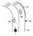
図1は、本発明の実施の形態の概要を説明するための概念図である。図1には、互いに隣接する第1レーンL1及び第2レーンL2が示されている。車両1は、第1レーンL1を走行している。この車両1は、周囲の物標と周囲のレーン(L1、L2)との位置関係を認識する機能を有している。 FIG. 1 is a conceptual diagram for explaining the outline of the embodiment of the present invention. In FIG. 1, the first lane L1 and the second lane L2 adjacent to each other are shown. The
具体的には、本実施の形態に係る車両1は、センサを用いて、車両1の周囲の状況を検出する。車両1は、センサによる検出結果に基づいて、車両1の周囲の物標に関する情報を取得することができる。ここで、車両1の周囲の物標は、大まかに、「移動物物標(moving target)TM」と「静止物物標(stationary target)TS」の2種類に区分される。 Specifically, the
移動物物標TMは、地表に対して移動している物標であり、典型的には他車両である。図1の例では、2つの移動物物標TM1、TM2が示されている。移動物物標TM1は、車両1と同じ第1レーンL1を走行する先行車である。移動物物標TM2は、第1レーンL1の隣りの第2レーンL2を走行する先行車である。 The moving object TM is a target moving with respect to the ground, and is typically another vehicle. In the example of FIG. 1, two moving object targets TM1 and TM2 are shown. The moving object target TM1 is a preceding vehicle traveling on the same first lane L1 as the
静止物物標TSは、地表上で静止している物標であり、典型例には路側物である。図1の例では、2つの静止物物標TS1、TS2が示されている。静止物物標TS1は、第2レーンL2の路側に立てられている交通標識である。静止物物標TS2は、第2レーンL2の路側に設置されているガードレールである。 The stationary target TS is a stationary target on the ground, and is typically a roadside. In the example of FIG. 1, two stationary targets TS1 and TS2 are shown. The stationary target TS1 is a traffic sign set on the roadside of the second lane L2. The stationary target TS2 is a guardrail installed on the roadside of the second lane L2.
また、本実施の形態に係る車両1は、地図データを参照して、車両1の周囲の「レーン配置(lane geometry)LG」を示す情報を取得する。より詳細には、地図データには、地図上の各レーンの境界位置を示す情報があらかじめ記録されている。また、車両1は、一般的なGPS(Global Positioning System)等を利用することによって、地図上の車両1の位置及び姿勢(方位)を認識することができる。よって、車両1は、地図データと車両1の位置及び姿勢を参照することによって、周囲のレーン(L1、L2)に関するレーン配置LGを認識することができる。 In addition, the
このように、センサの検出結果から、車両1の周囲の物標(TM1、TM2、TS1、TS2)に関する情報が得られる。また、地図データから、車両1の周囲のレーン配置LGを示す情報が得られる。よって、それら2つの情報を組み合わせることによって、周囲の物標(TM1、TM2、TS1、TS2)と周囲のレーン(L1、L2)との位置関係を認識することができる。例えば図1において、移動物物標TM1が車両1と同じ第1レーンL1を先行しており、移動物物標TM2が隣りの第2レーンL2を先行していることを認識することができる。 Thus, information on targets (TM1, TM2, TS1, TS2) around the
ここで、本実施の形態では、車両1の周囲のレーン配置LGが、正確な地図データから取得されることに留意されたい。上述の特許文献1(特開2007−253714号公報)では、車両前方のレーン形状が現在位置における道路曲率に基づいて推定されていたが、本実施の形態では、そのようなローカルな道路曲率に基づく推定は不要である。従って、特許文献1に開示された技術と比較して、車両1の周囲のレーン配置LGをより正確に把握することが可能となる。結果として、周囲の物標と周囲のレーンとの位置関係の認識精度が向上する。 Here, it should be noted that, in the present embodiment, the lane arrangement LG around the
但し、地図データから周囲のレーン配置LGを取得する際、地図上の車両1の位置及び姿勢が必要である。一般的には、GPS等を利用することにより、車両1の位置及び姿勢に関する情報を取得することができる。しかしながら、その車両位置姿勢情報には誤差が含まれ得る。この問題を克服するため、本実施の形態によれば、地図データから取得したレーン配置LGを“調整”する処理が行われる。そのような処理は、以下「レーン配置調整処理」と呼ばれる。 However, when acquiring surrounding lane arrangement LG from map data, the position and posture of the
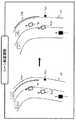
図2は、本実施の形態におけるレーン配置調整処理を説明するための概念図である。図2には、2種類のレーン配置LG、LG’が示されている。レーン配置LGは、地図データと車両1の位置及び姿勢から得られたレーン配置である。レーン配置LG’は、レーン配置LGを調整することにより得られるレーン配置である。調整後のレーン配置LG’は、以下「調整レーン配置LG’」と呼ばれる。 FIG. 2 is a conceptual diagram for explaining the lane arrangement adjustment processing in the present embodiment. Two types of lane arrangements LG and LG 'are shown in FIG. The lane arrangement LG is a lane arrangement obtained from the map data and the position and attitude of the
一般的に、車両はレーン内に位置し、路側物はレーン外に位置する。よって、移動物物標TMはレーン内に位置し、静止物物標TSはレーン外に位置する蓋然性は極めて高いと言える。しかしながら、図2に示される調整前のレーン配置LGの場合、移動物物標TM1、TM2がレーン境界とオーバーラップしており、静止物物標TS1、TS2が第2レーンL2内に入り込んでいる。これは、車両位置姿勢情報の誤差に起因すると考えられる。そこで、図2に示されるように、移動物物標TM1、TM2がレーン内に位置し、且つ、静止物物標TS1、TS2がレーン外に位置するように、レーン配置LGの調整が行われる。言い換えれば、移動物物標TM1、TM2がレーン内に位置し、且つ、静止物物標TS1、TS2がレーン外に位置するような調整レーン配置LG’が生成される。このように実情に沿った調整レーン配置LG’を用いることによって、周囲の物標(TM1、TM2、TS1、TS2)と周囲のレーン(L1、L2)との位置関係をより正確に認識することが可能となる。 Generally, the vehicle is located in the lane and the roadside is located outside the lane. Therefore, it can be said that the probability that the moving object TM is located in the lane and the stationary object TS is located outside the lane is extremely high. However, in the case of the lane arrangement LG before adjustment shown in FIG. 2, the moving objects TM1 and TM2 overlap the lane boundary, and the stationary objects TS1 and TS2 enter the second lane L2. . This is considered to be due to an error in the vehicle position and orientation information. Therefore, as shown in FIG. 2, adjustment of the lane arrangement LG is performed so that the moving objects TM1 and TM2 are located in the lane and the stationary objects TS1 and TS2 are located outside the lane. . In other words, the adjusted lane arrangement LG ′ is generated such that the moving objects TM1 and TM2 are located in the lane and the stationary objects TS1 and TS2 are located outside the lane. Thus, by using the adjustment lane arrangement LG 'according to the actual situation, the positional relationship between the surrounding target (TM1, TM2, TS1, TS2) and the surrounding lanes (L1, L2) can be recognized more accurately Is possible.
ここで、本実施の形態では、車両位置姿勢情報の誤差が許容されることに留意されたい。通常の発想ならば、ある情報に誤差が含まれる場合、その誤差を減らすための努力をするはずである。車両位置姿勢情報に誤差が含まれるのなら、その車両位置姿勢情報の精度をより向上させるための手法を模索するのが通常の発想である。しかし、本実施の形態は、通常の発想とは全く異なり、車両位置姿勢情報の誤差を許容する。その代わり、正確な地図データから取得されたレーン配置LGの方の“調整”が行われる。図2で示されたように、このようなレーン配置調整処理により、物標とレーンとの位置関係を精度良く認識することが可能となる。 Here, it should be noted that in the present embodiment, an error in the vehicle position and orientation information is allowed. Under normal thinking, if certain information contains an error, an effort should be made to reduce the error. If an error is included in the vehicle position and attitude information, it is a general idea to seek a method for further improving the accuracy of the vehicle position and attitude information. However, the present embodiment is completely different from the usual idea, and tolerates an error of the vehicle position and orientation information. Instead, "adjustment" is performed on the lane arrangement LG obtained from the accurate map data. As shown in FIG. 2, such lane arrangement adjustment processing makes it possible to accurately recognize the positional relationship between the target and the lane.
比較例として、車両位置姿勢情報の誤差を減らすことを考える。車両位置姿勢情報の誤差を減らすための一手法として、GPS衛星の台数を増やすことが考えられる。しかしながら、その場合、膨大な資源とコストが必要となる。本実施の形態によれば、GPS衛星の台数を増やす必要はなく、そのような問題は発生しない。 As a comparative example, it is considered to reduce the error of the vehicle position and orientation information. As one method for reducing the error of the vehicle position and attitude information, it is conceivable to increase the number of GPS satellites. However, in that case, enormous resources and costs are required. According to the present embodiment, it is not necessary to increase the number of GPS satellites, and such a problem does not occur.
他の手法として、数値計算を通して、車両位置姿勢情報を補正することが考えられる。しかし、車両位置姿勢情報を補正したとしても、その誤差が完全に無くなるわけではない。数値計算をより複雑にすることによって誤差をより減らすことができるかもしれないが、その分、計算負荷と計算時間が増大する。計算負荷と計算時間の増大は、物標とレーンとの位置関係を認識する速度の低下を招く。このことは、運転支援制御や自動運転制御の観点から好ましくない。誤差を減らすために数値計算を際限なく複雑化することはできるかもしれないが、その労力に見合うだけの効果は得られないのである。 As another method, it is conceivable to correct the vehicle position and attitude information through numerical calculation. However, even if the vehicle position and attitude information is corrected, the error does not necessarily disappear completely. It may be possible to reduce the error more by making the numerical calculations more complex, but the computational load and time will increase accordingly. The increase in calculation load and calculation time leads to a decrease in the speed of recognizing the positional relationship between the target and the lane. This is not preferable from the viewpoint of driving support control and automatic driving control. While it may be possible to make numerical calculations infinitely complex in order to reduce errors, it is not possible to obtain an effect that is commensurate with the effort.
一方、本実施の形態によれば、車両位置姿勢情報の誤差が許容される。よって、車両位置姿勢情報の誤差を低減するための複雑な数値計算は不要である。その代わり、本実施の形態では、レーン配置調整処理が行われる。ここで、レーン配置調整処理は、やみくもに行われるわけではない。レーン配置調整処理において、「移動物物標TMはレーン内に位置し、静止物物標TSはレーン外に位置する」という制約条件が課される。このような制約条件を課すことにより、レーン配置調整処理に要する計算を早期に収束させることが可能となる。すなわち、計算負荷及び計算時間をむやみに増大させることなく、レーン配置調整処理を行うことができる。「移動物物標TMはレーン内に位置し、静止物物標TSはレーン外に位置する」という制約条件は、本分野ならではのものである。本実施の形態は、本分野に特有な制約条件を利用して、計算負荷及び計算時間を軽減しているとも言える。 On the other hand, according to the present embodiment, an error in the vehicle position and orientation information is allowed. Therefore, complicated numerical calculation for reducing the error of the vehicle position and orientation information is unnecessary. Instead, lane arrangement adjustment processing is performed in the present embodiment. Here, the lane arrangement adjustment process is not performed blindly. In the lane arrangement adjustment process, the constraint that “moving object TM is located in the lane and stationary object TS is located outside the lane” is imposed. By imposing such constraint conditions, it is possible to quickly converge the calculations required for the lane arrangement adjustment processing. That is, the lane arrangement adjustment process can be performed without unduly increasing the calculation load and calculation time. The constraint that "the moving object TM is located in the lane and the stationary object TS is located outside the lane" is unique to this field. It can also be said that the present embodiment reduces the computational load and time by utilizing constraints unique to this field.
以上に説明されたように、本実施の形態は、新たな発想に依拠している。そして、本実施の形態によれば、車両1の周囲における物標とレーンとの位置関係を精度良く認識することが可能となる。以下、本実施の形態を実現するための構成及び処理フローを詳細に説明する。 As described above, the present embodiment relies on new ideas. Then, according to the present embodiment, it is possible to accurately recognize the positional relationship between the target and the lane around the
2.構成
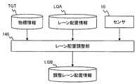
図3は、本実施の形態に係る物標レーン関係認識装置の構成例を概略的に示すブロック図である。物標レーン関係認識装置は、車両1に搭載され、車両1の周囲における物標とレーンとの位置関係を認識する処理を行う。詳細には、物標レーン関係認識装置は、センサ10、GPS受信器20、通信装置30、記憶装置40、及び処理装置100を備えている。2. Configuration FIG. 3 is a block diagram schematically showing a configuration example of a target lane relationship recognition device according to the present embodiment. The target lane relationship recognition device is mounted on the
センサ10は、車両1の周囲の状況を検出する。センサ10としては、ライダー(LIDAR: Laser Imaging Detection and Ranging)、ミリ波レーダー、ステレオカメラ等が例示される。ライダーは、光を利用して車両1の周囲の物標を検出する。ミリ波レーダーは、電波を利用して車両1の周囲の物標を検出する。ステレオカメラは、車両1の周囲の状況を撮像する。センサ10は、検出した情報を処理装置100に送る。 The
GPS受信器20は、複数のGPS衛星から送信される信号を受信し、受信信号に基づいて車両1の位置及び方位(姿勢)を算出する。GPS受信器20は、算出した情報を処理装置100に送る。 The
通信装置30は、V2X通信(車車間通信および路車間通信)を行う。具体的には、通信装置30は、他の車両との間でV2V通信(車車間通信)を行う。また、通信装置30は、周囲のインフラとの間でV2I通信(路車間通信)を行う。V2X通信を通して、通信装置30は、車両1の周囲の環境に関する情報を取得することができる。例えば、通信装置30は、車両1の周囲の他車両が走行している走行レーンを示す他車両レーン情報を取得することができる。通信装置30は、取得した情報を処理装置100に送る。 The
記憶装置40には、各種情報が格納される。記憶装置40としては、RAM(Random Access Memory)、ROM(Read Only Memory)、不揮発性メモリ、HDD(Hard Disk Drive)、DVD(Digital Versatile Disk)等が例示される。 The
より詳細には、記憶装置40には、地図データMAPが格納される。地図データMAPには、地図上の各レーンの境界位置を示す情報があらかじめ記録されている。各レーンの境界位置は、複数の要素の集合で表される。例えば、各レーンの境界位置は、複数の点の集合(点群)で表される。あるいは、各レーンの境界位置は、複数の線の集合(線群)で表されてもよい。 More specifically, the
また、記憶装置40には、車両位置姿勢情報POS、物標情報TGT、レーン配置情報LGA、調整レーン配置情報LGB、及び物標レーン関係情報TLRが格納される。これら情報は、後述の物標レーン関係認識処理において、生成され、使用される。 Further, the
更に、記憶装置40には、処理プログラムPROGが格納される。この処理プログラムPROGは、処理装置100によって読み出され、実行されるコンピュータプログラムである。処理プログラムPROGは、コンピュータ読み取り可能な記録媒体に記録されていてもよい。 Further, the
処理装置100は、各種情報処理を行うプロセッサである。具体的には、処理装置100は、CPU(Central Processing Unit)を含んでいる。処理装置100と記憶装置40の一部がマイクロコンピュータを構成していてもよい。 The
処理装置100は、記憶装置40から処理プログラムPROGを読み出し、実行する。それにより、処理装置100は、本実施の形態に係る「物標レーン関係認識処理」を実現する。物標レーン関係認識処理において、処理装置100は、センサ10、GPS受信器20、通信装置30から必要な情報を受け取り、また、記憶装置40から必要な情報を読み出す。そして、処理装置100は、情報処理を行い、生成した情報を記憶装置40に書き込む。 The
図4は、物標レーン関係認識処理に関連する処理装置100の機能構成を示すブロック図である。処理装置100は、機能ブロックとして、物標情報取得部110、車両位置姿勢取得部120、レーン配置取得部130、レーン配置調整部140、情報生成部150、運転支援制御部160、及び自動運転制御部170を備えている。これら機能ブロックは、処理装置100が処理プログラムPROGを実行することにより実現される。以下、これら機能ブロックによる物標レーン関係認識処理について詳しく説明する。 FIG. 4 is a block diagram showing a functional configuration of the
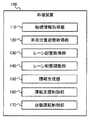
3.物標レーン関係認識処理
図5は、本実施の形態に係る物標レーン関係認識処理を示すフローチャートである。図6は、本実施の形態に係る物標レーン関係認識処理を示すブロック図である。図5及び図6を適宜参照しながら、本実施の形態に係る物標レーン関係認識処理について説明する。3. Target Lane Relationship Recognition Processing FIG. 5 is a flowchart showing target lane relationship recognition processing according to the present embodiment. FIG. 6 is a block diagram showing target lane relation recognition processing according to the present embodiment. Target lane relation recognition processing according to the present embodiment will be described with reference to FIGS. 5 and 6 as appropriate.
3−1.ステップS110:物標情報取得処理
物標情報取得部110は、物標情報取得処理を行う。具体的には、物標情報取得部110は、センサ10によって検出された検出情報を受け取る。そして、物標情報取得部110は、センサ10からの検出情報に基づき、周知の手法により、車両1の周囲の移動物物標TM及び静止物物標TSを認識する。そして、物標情報取得部110は、認識した移動物物標TM及び静止物物標TSに関する物標情報TGTを生成する。3-1. Step S110: Target Object Information Acquisition Process The target object
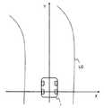
物標情報TGTは、基準座標系における移動物物標TM及び静止物物標TSの位置に関連する情報を含む。基準座標系としては、任意の直交座標系が利用可能である。図7には、基準座標系の一例が示されている。本例では、座標原点は、車両1の2つの後輪の中間点である。X軸は、車両1の左右方向に平行な軸であり、右方向が正方向に設定されている。Y軸は、車両1の前後方向に平行な軸であり、前方が正方向に設定されている。この基準座標系は、車両1と共に移動する。 The target information TGT includes information related to the positions of the moving target TM and the stationary target TS in the reference coordinate system. Any orthogonal coordinate system can be used as a reference coordinate system. FIG. 7 shows an example of the reference coordinate system. In this example, the coordinate origin is the midpoint of the two rear wheels of the
図7に示されるように、各物標の範囲(サイズ)は、複数の検出点pdによって規定される。複数の検出点pdは、センサ10からの検出情報から抽出可能である。また、同一の物標に関する複数の検出点pdの集合は、クラスタリング処理により決定される。物標の位置に関連する情報の第1の例は、当該物標の範囲を規定するこのような複数の検出点pdのそれぞれの位置である。 As shown in FIG. 7, the range (size) of each target is defined by a plurality of detection points pd. The plurality of detection points pd can be extracted from the detection information from the
物標の位置に関連する情報の第2の例は、当該物標の代表点prの位置である。例えば、代表点prは、上記複数の検出点pdに基づいて推定される物標の中心点である。あるいは、代表点prは、複数の検出点pdの重心位置であってもよい。あるいは、代表点prは、複数の検出点pdのうち任意の1つであってもよい。 The second example of the information related to the position of the target is the position of the representative point pr of the target. For example, the representative point pr is a center point of the target estimated based on the plurality of detection points pd. Alternatively, the representative point pr may be the center of gravity of the plurality of detection points pd. Alternatively, the representative point pr may be any one of the plurality of detection points pd.
物標の位置に関連する情報の第3の例は、当該物標の軌跡である。物標の軌跡は、代表点prあるいは検出点pdの時系列位置で与えられる。 A third example of information related to the position of a target is the trajectory of the target. The locus of the target is given by the time-series position of the representative point pr or the detection point pd.
物標情報TGTは、移動物物標TM及び静止物物標TSの各々の位置に関連する情報として、上記3種類の例のうち少なくとも1つを含んでいる。物標情報TGTは、上記3種類の例のうち2以上の組み合わせを含んでいてもよい。 The target information TGT includes at least one of the above three types of information as information related to the position of each of the moving target TM and the stationary target TS. The target information TGT may include a combination of two or more of the above three types of examples.
移動物物標TMについては、速度(速度ベクトル)を算出することも可能である。具体的には、移動物物標TMの代表点prあるいは検出点pdの時系列位置から、その移動物物標TMの速度を算出することができる。物標情報TGTは、位置に関連する情報に加えて、移動物物標TMの速度を含んでいてもよい。 For a moving object TM, it is also possible to calculate the velocity (velocity vector). Specifically, the velocity of the moving object TM can be calculated from the time-series position of the representative point pr or the detection point pd of the moving object TM. The target information TGT may include the speed of the moving object TM in addition to the information related to the position.
3−2.ステップS120:車両位置姿勢取得処理
車両位置姿勢取得部120は、車両位置姿勢取得処理を行う。具体的には、上述のGPS受信器20が、GPS衛星からの信号に基づいて、車両1の位置及び方位(姿勢)を算出する。車両位置姿勢取得部120は、GPS受信器20によって算出された情報を受け取り、車両1の位置及び姿勢を示す車両位置姿勢情報POSを出力する。この車両位置姿勢情報POSにおいて、車両1の位置は、例えば、緯度及び経度で与えられる。3-2. Step S120: Vehicle Position and Attitude Acquisition Process The vehicle position and
図8は、車両位置姿勢取得処理の変形例を示している。変形例では、車両位置姿勢取得部120は、センサ10による検出情報と地図データMAPも利用する。より詳細には、センサ10は、車両1の周囲の環境を撮像するカメラを含み、撮像データを出力する。車両位置姿勢取得部120は、その撮像データから特徴点を抽出する。特徴点としては、白線やランドマーク(例えば、看板、道路標識)が挙げられる。一方、地図データMAPにも、特徴点があらかじめ登録されている。車両位置姿勢取得部120は、GPS受信器20からの情報に基づいて車両1の大まかな位置を把握し、車両1の周囲の地図データMAPを読み込む。そして、車両位置姿勢取得部120は、撮像データから抽出された特徴点と地図データMAPに登録されている特徴点とが最も整合するような車両1の位置及び姿勢を探索する。このような手法によっても、車両位置姿勢情報POSを取得することができる。 FIG. 8 shows a modification of the vehicle position and attitude acquisition process. In the modification, the vehicle position and
尚、本実施の形態では、車両位置姿勢情報POSの誤差は許容される。そのため、車両位置姿勢情報POSの誤差を減らすための過度な計算処理は不要である。図8で示されたような変形例が採用される場合も、ある程度の精度が得られれば十分である。 In the present embodiment, an error of the vehicle position and attitude information POS is allowed. Therefore, excessive calculation processing for reducing the error of the vehicle position and orientation information POS is unnecessary. Even when the modification as shown in FIG. 8 is adopted, it is sufficient if a certain degree of accuracy can be obtained.
3−3.ステップS130:レーン配置取得処理
レーン配置取得部130は、レーン配置取得処理を行う。具体的には、レーン配置取得部130は、車両位置姿勢情報POSを読み込み、車両1の位置及び姿勢を把握する。その一方で、地図データMAPには、地図上の各レーンの境界位置を示す情報が記録されている。レーン配置取得部130は、車両1の位置に基づいて、車両1の周囲のレーンの境界位置を地図データMAPから取得する。そして、レーン配置取得部130は、車両1の位置及び姿勢を考慮することによって、地図上のレーンの境界位置を上記の基準座標系におけるレーン配置LGに変換する。3-3. Step S130: Lane Arrangement Acquisition Process The lane
図9は、基準座標系におけるレーン配置LGを示している。レーンの境界は、複数の要素(点、線)の集合で表されている。その集合の全体的な形状が「レーン形状(lane shape)」である。レーン形状は、集合を構成する複数の要素間の相対的位置関係と言うこともできる。また、基準座標系における集合の位置が「レーン位置(lane position)」である。また、基準座標系における集合の傾き(回転)が「レーン傾き(lane orientation)」である。本実施の形態における「レーン配置(lane geometry)LG」とは、それらレーン形状、レーン位置、及びレーン傾きを包含する概念である。レーン配置LGは、基準座標系における複数の要素の集合の配置であると言える。 FIG. 9 shows the lane arrangement LG in the reference coordinate system. The boundaries of the lanes are represented by a set of multiple elements (points, lines). The overall shape of the set is the "lane shape". The lane shape can also be said to be a relative positional relationship between a plurality of elements constituting a set. Also, the position of the set in the reference coordinate system is the "lane position". Further, the inclination (rotation) of the set in the reference coordinate system is "lane orientation". “Lane geometry LG” in the present embodiment is a concept including the lane shape, the lane position, and the lane inclination. The lane arrangement LG can be said to be an arrangement of a set of a plurality of elements in the reference coordinate system.
このように、レーン配置取得部130は、地図データMAP及び車両位置姿勢情報POSに基づいて、車両1の周囲のレーン配置LGを取得する。そのレーン配置LGを示す情報がレーン配置情報LGAである。レーン配置取得部130は、レーン配置情報LGAを生成し、出力する。 As described above, the lane
3−4.ステップS140:レーン配置調整処理
レーン配置調整部140は、既出の図2で示されたレーン配置調整処理を行う。具体的には、レーン配置調整部140は、レーン配置情報LGAを読み込み、レーン配置情報LGAで示されるレーン配置LGを調整し、調整レーン配置LG’を生成する。このとき、レーン配置調整部140は、物標情報TGTも読み込み、「移動物物標TMはレーン内に位置し、静止物物標TSはレーン外に位置する」という制約条件を課す。すなわち、レーン配置調整部140は、当該制約条件が満たされるようにレーン配置LGを調整し、調整レーン配置LG’を生成する。その調整レーン配置LG’を示す情報が調整レーン配置情報LGBである。レーン配置調整部140は、調整レーン配置情報LGBを生成し、出力する。3-4. Step S140: Lane Arrangement Adjustment Process The lane
上述の通り、レーン配置調整処理は、車両位置姿勢情報POSの誤差を許容する代わりに行われる。車両位置姿勢情報POSの誤差とは、車両1の位置及び姿勢の誤差であり、レーン配置LGのうちレーン位置とレーン傾きに影響を与える。よって、レーン配置調整処理においては、レーン位置とレーン傾きが調整されるとよい。レーン形状(集合を構成する複数の要素間の相対的位置関係)は正確であるため、調整する必要はない。レーン形状を変えずに維持することによって、レーン配置調整処理の精度が向上する。 As described above, the lane arrangement adjustment process is performed instead of allowing the error of the vehicle position and orientation information POS. The error of the vehicle position and attitude information POS is an error of the position and attitude of the
但し、本実施の形態は、レーン形状も変更する場合を排除しない。例えば、計算量を減らすために、レーン配置LGを表す複数の要素のうち一部を間引いて、レーン配置LGを単純化してもよい。この場合、レーン配置調整処理において、レーン形状も多少変わる。元のレーン形状が十分に反映されているのであれば、このようにレーン形状を変更してもよい。 However, this embodiment does not exclude the case where the lane shape is also changed. For example, in order to reduce the amount of calculation, some of the elements representing the lane arrangement LG may be thinned to simplify the lane arrangement LG. In this case, the lane shape also changes somewhat in the lane arrangement adjustment process. If the original lane shape is sufficiently reflected, the lane shape may be changed in this manner.
以下、レーン配置調整処理の様々な具体例を説明する。 Hereinafter, various specific examples of the lane arrangement adjustment process will be described.
<第1の例>
物標情報TGTは、移動物物標TMの代表点pr(図7参照)の位置を含んでいる。この場合、レーン配置調整部140は、「移動物物標TMの代表点prがレーン内に位置し、静止物物標TSがレーン外に位置する」という制約条件が満たされるように、レーン配置調整処理を行う。<First example>
The target information TGT includes the position of the representative point pr (see FIG. 7) of the moving object target TM. In this case, the lane
例えば、レーン位置及びレーン傾きを変換する複数種類の変換関数があらかじめ用意される。レーン配置調整部140は、レーン配置LGに複数種類の変換関数を適用することにより、複数種類の変換レーン配置をそれぞれ生成する。そして、レーン配置調整部140は、複数種類の変換レーン配置の中から上記制約条件を満たすものを候補として選択する。候補が1つの場合、当該1つの候補が調整レーン配置LG’として選択される。 For example, plural types of conversion functions for converting lane position and lane slope are prepared in advance. The lane
候補が複数存在する場合、レーン配置調整部140は、複数の候補のうち1つを調整レーン配置LG’として選択する。例えば、レーン配置LG上のいくつかの点がサンプル点として抽出され、変換関数によるサンプル点の移動量の平均値が“変換量”として算出される。そして、その変換量が最も小さかった候補が、調整レーン配置LG’として選択される。 If there are a plurality of candidates, the lane
あるいは、各候補において、移動物物標TMの代表点prとその移動物物標TMが属するレーンの中心線との距離が算出され、全ての移動物物標TMに関する当該距離の総和が算出される。そして、その総和が最も小さい候補が、調整レーン配置LG’として選択される。 Alternatively, in each candidate, the distance between the representative point pr of the moving object TM and the center line of the lane to which the moving object TM belongs is calculated, and the sum of the distances for all the moving objects TM is calculated. Ru. Then, the candidate with the smallest sum is selected as the adjustment lane arrangement LG ′.
代表点prが用いられる場合、レーン配置調整処理がシンプルになる。このことは、計算負荷軽減の観点から好適である。 When the representative point pr is used, the lane arrangement adjustment process becomes simple. This is preferable from the viewpoint of reduction of computational load.
<第2の例>
物標情報TGTは、移動物物標TMの範囲(サイズ)を規定する複数の検出点pd(図7参照)の位置を含んでいる。この場合、レーン配置調整部140は、「単一の移動物物標TMに関する複数の検出点pdの全てが同一レーン内に位置し、静止物物標TSがレーン外に位置する」という制約条件が満たされるように、レーン配置調整処理を行う。その他は第1の例と同様である。第2の例によれば、移動物物標TMの範囲(サイズ)が考慮されるため、レーン配置調整処理の精度がより高くなる。Second Example
The target information TGT includes the positions of a plurality of detection points pd (see FIG. 7) which define the range (size) of the moving object target TM. In this case, the lane
<第3の例>
物標情報TGTは、移動物物標TMの軌跡を含んでいる。この場合、レーン配置調整部140は、「単一の移動物物標TMの軌跡が同一レーン内に位置し、静止物物標TSがレーン外に位置する」という制約条件が満たされるように、レーン配置調整処理を行う。その他は第1の例と同様である。第3の例によれば、移動物物標TMの軌跡が考慮されるため、レーン配置調整処理の精度がより高くなる。<Third example>
The target information TGT includes the trajectory of the moving object TM. In this case, the lane
<第4の例>
第4の例は、既出の制約条件に対し更なる制約条件を追加する。つまり、第4の例は、補助的に用いられる。より詳細には、第4の例において、物標情報TGTは、移動物物標TMの位置及び速度を含んでいる。レーン配置調整部140は、それら位置及び速度に基づいて、一定時間後の移動物物標TMの将来位置を予測する。そして、レーン配置調整部140は、「移動物物標TMの将来位置が現在と同じレーン内に位置すること」を制約条件に追加する。将来位置を考慮した制約条件が追加されるため、レーン配置調整処理の精度がより一層高くなる。Fourth Example
The fourth example adds an additional constraint to the already mentioned constraint. That is, the fourth example is used supplementary. More specifically, in the fourth example, the target information TGT includes the position and velocity of the moving object target TM. The lane
<第5の例>
第5の例は、既出の制約条件に対し更なる制約条件を追加する。つまり、第5の例は、補助的に用いられる。より詳細には、第5の例において、物標情報TGTは、移動物物標TMの位置及び速度を含んでいる。レーン配置調整部140は、移動物物標TMに最も近いレーン境界の接線を算出する。そして、レーン配置調整部140は、「算出した接線と移動物物標TMの速度ベクトルとがなす角度が閾値以下となること」を制約条件に追加する。この追加制約条件は、移動物物標TMの進行方向が調整レーン配置LG’に違和感無く整合していることを意味する。このような制約条件が追加されることにより、レーン配置調整処理の精度がより一層高くなる。<Fifth example>
The fifth example adds an additional constraint to the existing one. That is, the fifth example is used supplementary. More specifically, in the fifth example, the target information TGT includes the position and velocity of the moving object target TM. The lane
<第6の例>
第6の例は、既出の制約条件に対し更なる制約条件を追加する。つまり、第6の例は、補助的に用いられる。より詳細には、第6の例では、「レーン変更物標TLC」が考慮される。レーン変更物標TLCは、レーン変更中の移動物物標であり、これまでの移動物物標TMとは別に扱われる。<Sixth example>
The sixth example adds an additional constraint to the existing constraint. That is, the sixth example is used supplementary. More specifically, in the sixth example, “lane change target TLC” is considered. The lane change target TLC is a mobile target during the lane change, and is treated separately from the previous mobile target TM.
レーン変更物標TLCの認識は、次の通りである。例えば、センサ10は、カメラを含んでいる。物標情報取得部110は、カメラによって得られた撮像情報に基づいて、車両1の周囲のレーン変更物標TLCを認識する。例えば、物標情報取得部110は、ウィンカーの点滅を認識することによって、レーン変更物標TLCを認識することができる。あるいは、物標情報取得部110は、撮像情報においてレーン境界上に位置している他車両をレーン変更物標TLCとして認識することができる。 The recognition of the lane change target TLC is as follows. For example, the
物標情報TGTは、基準座標系におけるレーン変更物標TLCの位置に関連する情報も含む。この場合、図10に示されるように、レーン配置調整部140は、「レーン変更物標TLCがレーン境界とオーバーラップすること」を制約条件に追加する。レーン変更物標TLCも考慮した制約条件が追加されるため、レーン配置調整処理の精度がより一層高くなる。 The target information TGT also includes information related to the position of the lane change target TLC in the reference coordinate system. In this case, as shown in FIG. 10, the lane
<第7の例>
第7の例は、既出の制約条件に対し更なる制約条件を追加する。つまり、第7の例は、補助的に用いられる。より詳細には、図11に示されるように、レーン配置調整部140は、V2X通信を行う通信装置30から情報を受け取る。その情報は、車両1の周囲の他車両が走行している走行レーンを示す他車両レーン情報を含んでいる。この場合、レーン配置調整部140は、「移動物物標TMのいずれかが、他車両レーン情報で示される走行レーン内に位置すること」を制約条件に追加する。V2X通信を通して得られる情報を考慮した制約条件が追加されるため、レーン配置調整処理の精度がより一層高くなる。<Seventh example>
The seventh example adds additional constraints to the already mentioned constraints. That is, the seventh example is used supplementary. More specifically, as illustrated in FIG. 11, the lane
<第8の例>
第8の例は、既出の制約条件に対し更なる制約条件を追加する。つまり、第8の例は、補助的に用いられる。第8の例では、「車両1の周囲の白線位置」が考慮される。Eighth Example
The eighth example adds an additional constraint to the existing constraint. That is, the eighth example is used supplementary. In the eighth example, the "white line position around the
より詳細には、図12に示されるように、レーン配置調整部140は、センサ10から検出情報を受け取る。センサ10は、カメラを含んでいる。レーン配置調整部140は、カメラによって得られた撮像情報に基づいて、周知の白線認識処理を行う。この白線認識処理により、レーン配置調整部140は、基準座標系における車両1の周囲の白線位置を認識する。典型的には、白線位置は、複数の画素の集合で表される。このとき、各白線画素と最近傍のレーン境界との間の距離を算出することができる。そして、認識された全ての白線画素に関する距離の総和あるいは平均値が、「白線位置とレーン境界との間の距離」として算出される。 More specifically, as shown in FIG. 12, the lane
そして、レーン配置調整部140は、「白線位置とレーン境界との間の距離が閾値以下となること」を制約条件に追加する。あるいは、第1の例で説明されたような複数種類の変換関数が用いられる場合、レーン配置調整部140は、制約条件を満たす候補の中から「白線位置とレーン境界との間の距離」が最小となる1つの候補を、調整レーン配置LG’として選択する。この追加制約条件は、調整レーン配置LG’が実際の白線位置に整合していることを意味する。このような制約条件が追加されることにより、レーン配置調整処理の精度がより一層高くなる。 Then, the lane
<第9の例>
渋滞時、移動物物標TMとして判定されるべき他車両が静止物物標TSと誤判定される可能性がある。その場合にレーン配置調整処理を行うと、他車両がレーン外に出てしまうおそれがある。そこで、渋滞時、レーン配置調整部140は、レーン配置調整処理をスキップしてもよい。この場合、レーン配置調整部140は、レーン配置情報LGAをそのまま調整レーン配置情報LGBとして出力する。渋滞の判定には、例えば、道路交通情報あるいは視野内の物標の平均速度を利用することができる。<The ninth example>
At the time of traffic congestion, there is a possibility that other vehicles to be determined as the moving object TM may be erroneously determined as the stationary object TS. In this case, if the lane arrangement adjustment processing is performed, there is a risk that other vehicles may go out of the lane. Therefore, at the time of traffic jam, the lane
尚、矛盾しない限りにおいて、第1〜第9の例のうちいくつかの組み合わせも可能である。 In addition, as long as there is no contradiction, some combinations of the first to ninth examples are also possible.
3−5.ステップS150:情報生成処理
情報生成部150は、情報生成処理を行う。具体的には、情報生成部150は、物標情報TGTと調整レーン配置情報LGBを読み込む。そして、情報生成部150は、各物標と調整レーン配置LG’との位置関係を示す物標レーン関係情報TLRを生成する。3-5. Step S150: Information Generation Process The
例えば、物標レーン関係情報TLRは、各物標がレーンの内にいるか外にいるか、移動物物標TMがどのレーンに属しているか、等の情報を含む。例えば、図2で示された調整レーン配置LG’の場合、物標レーン関係情報TLRは、移動物物標TM1が第1レーンL1に属していること、移動物物標TM2が第2レーンL2に属していること、静止物物標TS1及びTS2がレーン外(第2レーンL2の路側)に位置していること、等の情報を含む。 For example, the target lane relationship information TLR includes information such as whether each target is inside or outside the lane, to which lane the moving object TM belongs. For example, in the case of the adjusted lane arrangement LG ′ shown in FIG. 2, the target lane relation information TLR indicates that the moving object TM1 belongs to the first lane L1, and the moving object TM2 is in the second lane L2. And the stationary object targets TS1 and TS2 are located outside the lane (the roadside of the second lane L2).
3−6.ステップS160:運転支援制御、自動運転制御
運転支援制御部160は、物標レーン関係情報TLRを利用して、運転支援制御を行う。運転支援制御の一例として、「追従走行」を考える。運転支援制御部160は、車両1と同じレーンを先行している移動物物標TMのうち最も近いものを先行車(追従ターゲット)として判定する。図1及び図2で示された例では、車両1と同じ第1レーンL1を先行する移動物物標TM1が先行車である。そして、運転支援制御部160は、一定の車間距離を空けて先行車に追従するよう車両1を制御する。3-6. Step S160: Driving support control, automatic driving control The driving
自動運転制御部170は、物標レーン関係情報TLRを利用して、自動運転制御を行う。自動運転制御でも、上述のような「追従走行」が可能である。他の例として、「自動レーン変更」を考える。先行車の速度が制限速度を下回っており、且つ、隣接レーンにおける車両1の近傍の一定範囲に他車両が存在しない場合、自動運転制御部170は、隣接レーンに移動するよう車両1を制御する。 The automatic
4.効果
以上に説明されたように、本実施の形態によれば、車両1は、センサ10による検出結果に基づいて、車両1の周囲の移動物物標TM及び静止物物標TSに関する物標情報を取得する。また、車両1は、地図データMAPと車両位置姿勢情報POSとに基づいて、車両1の周囲のレーン配置LGを取得する。更に、車両1は、レーン配置調整処理を行い、実情に沿った制約条件を満たす調整レーン配置LG’を生成する。その調整レーン配置LG’を用いることによって、車両1の周囲における物標とレーンとの位置関係を精度良く認識することが可能となる。4. As described above, according to the present embodiment, the
特許文献1(特開2007−253714号公報)に開示されている技術では、車両前方のレーン形状が現在位置における道路曲率に基づいて推定されていた。しかしながら、本実施の形態では、そのようなローカルな道路曲率に基づく推定は不要である。本実施の形態によれば、車両1の周囲のレーン配置LGが、正確な地図データMAPから取得される。従って、特許文献1に開示されている技術と比較して、車両1の周囲のレーン配置LGをより正確に把握することが可能となる。結果として、周囲の物標と周囲のレーンとの位置関係の認識精度が向上する。 In the technology disclosed in Patent Document 1 (Japanese Patent Laid-Open No. 2007-253714), the lane shape in front of the vehicle is estimated based on the road curvature at the current position. However, in the present embodiment, such estimation based on the local road curvature is not necessary. According to the present embodiment, the lane arrangement LG around the
但し、地図データMAPからレーン配置LGを取得するには車両位置姿勢情報POSが必要であり、その車両位置姿勢情報POSには誤差が含まれ得る。本実施の形態では、その車両位置姿勢情報POSの誤差を考慮して、レーン配置調整処理が行われる。つまり、車両位置姿勢情報POSの誤差が相殺されるように、レーン配置LGの調整が行われる。このようなレーン配置調整処理により、周囲の物標と周囲のレーンとの位置関係の認識精度が更に向上する。 However, in order to acquire lane arrangement LG from map data MAP, vehicle position and attitude information POS is required, and an error may be included in the vehicle position and attitude information POS. In the present embodiment, the lane arrangement adjustment processing is performed in consideration of the error of the vehicle position and orientation information POS. That is, adjustment of the lane arrangement LG is performed so that the error of the vehicle position and orientation information POS is offset. Such lane arrangement adjustment processing further improves the recognition accuracy of the positional relationship between the surrounding target and the surrounding lane.
レーン配置調整処理は、やみくもに行われるわけではない。レーン配置調整処理において、「移動物物標TMはレーン内に位置し、静止物物標TSはレーン外に位置する」という制約条件が課される。このような制約条件を課すことにより、レーン配置調整処理に要する計算を早期に収束させることが可能となる。すなわち、計算負荷及び計算時間をむやみに増大させることなく、レーン配置調整処理を行うことができる。「移動物物標TMはレーン内に位置し、静止物物標TSはレーン外に位置する」という制約条件は、本分野ならではのものである。本実施の形態は、本分野に特有な制約条件を利用して、計算負荷及び計算時間を軽減しているとも言える。 Lane arrangement adjustment processing is not performed blindly. In the lane arrangement adjustment process, the constraint that “moving object TM is located in the lane and stationary object TS is located outside the lane” is imposed. By imposing such constraint conditions, it is possible to quickly converge the calculations required for the lane arrangement adjustment processing. That is, the lane arrangement adjustment process can be performed without unduly increasing the calculation load and calculation time. The constraint that "the moving object TM is located in the lane and the stationary object TS is located outside the lane" is unique to this field. It can also be said that the present embodiment reduces the computational load and time by utilizing constraints unique to this field.
本実施の形態では、車両位置姿勢情報POSの誤差が許容されることに留意されたい。通常の発想ならば、ある情報に誤差が含まれる場合、その誤差を減らすための努力をするはずである。車両位置姿勢情報POSに誤差が含まれるのなら、その車両位置姿勢情報POSの精度をより向上させるための手法を模索するのが通常の発想である。しかし、本実施の形態は、通常の発想とは全く異なり、車両位置姿勢情報POSの誤差を許容する。その代わりに、レーン配置調整処理が行われるのである。 It should be noted that in the present embodiment, an error of the vehicle position and attitude information POS is allowed. Under normal thinking, if certain information contains an error, an effort should be made to reduce the error. If an error is included in the vehicle position and attitude information POS, it is a general idea to seek a method for further improving the accuracy of the vehicle position and attitude information POS. However, the present embodiment is completely different from the usual idea, and allows an error of the vehicle position and orientation information POS. Instead, lane arrangement adjustment processing is performed.
比較例として、車両位置姿勢情報POSの誤差を減らすことを考える。車両位置姿勢情報POSの誤差を減らすための一手法として、GPS衛星の台数を増やすことが考えられる。しかしながら、この場合、膨大な資源とコストが必要となる。本実施の形態によれば、GPS衛星の台数を増やす必要はなく、そのような問題は発生しない。 As a comparative example, it is considered to reduce the error of the vehicle position and attitude information POS. It is conceivable to increase the number of GPS satellites as a method of reducing the error of the vehicle position and attitude information POS. However, in this case, enormous resources and costs are required. According to the present embodiment, it is not necessary to increase the number of GPS satellites, and such a problem does not occur.
以上に説明されたように、本実施の形態は、新たな発想に依拠している。そして、本実施の形態によれば、車両1の周囲における物標とレーンとの位置関係を精度良く認識することが可能となる。 As described above, the present embodiment relies on new ideas. Then, according to the present embodiment, it is possible to accurately recognize the positional relationship between the target and the lane around the
1 車両
10 センサ
20 GPS受信器
30 通信装置
40 記憶装置
100 処理装置
110 物標情報取得部
120 車両位置姿勢取得部
130 レーン配置取得部
140 レーン配置調整部
150 情報生成部
160 運転支援制御部
170 自動運転制御部
L1 第1レーン
L2 第2レーン
LG レーン配置
LG’ 調整レーン配置
LGA レーン配置情報
LGB 調整レーン配置情報
MAP 地図データ
POS 車両位置姿勢情報
PROG 処理プログラム
TGT 物標情報
TLR 物標レーン関係情報
TLC レーン変更物標
TM、TM1、TM2 移動物物標
TS、TS1、TS2 静止物物標
Claims (10)
Translated fromJapanese前記車両の周囲の状況を検出するセンサと、
地図上のレーンの境界位置を示す地図データが格納された記憶装置と、
処理装置と
を備え、
前記処理装置は、
前記センサによる検出結果に基づいて、前記車両の周囲の移動物物標及び静止物物標に関する物標情報を取得する物標情報取得処理と、
前記地図データと前記車両の位置及び姿勢とに基づいて、前記車両の周囲のレーン配置を示すレーン配置情報を取得するレーン配置取得処理と、
前記レーン配置を調整することによって、前記移動物物標がレーン内に位置し、且つ、前記静止物物標がレーン外に位置するという条件を満たす調整レーン配置を生成するレーン配置調整処理と、
前記移動物物標と前記調整レーン配置との位置関係を示す物標レーン関係情報を生成する情報生成処理と
を行うように構成され、
前記レーン配置は、複数の要素の集合で表され、
前記処理装置は、前記複数の要素間の相対的位置関係を維持しながら前記レーン配置調整処理を行う
物標レーン関係認識装置。A target lane relation recognition device mounted on a vehicle,
A sensor for detecting a situation around the vehicle;
A storage device storing map data indicating lane boundary positions on the map;
Processing equipment and
The processing unit
Target information acquisition processing for acquiring target information on moving objects and stationary objects around the vehicle based on the detection result of the sensor;
Lane arrangement acquisition processing for acquiring lane arrangement information indicating lane arrangement around the vehicle based on the map data and the position and posture of the vehicle;
A lane arrangement adjustment process that generates an adjustment lane arrangement that satisfies the condition that the moving object is located in the lane and the stationary object is located outside the lane by adjusting the lane arrangement;
Information generation processing for generating target lane relationship information indicating a positional relationship between the moving object and the adjustment lane arrangement;
The lane arrangement is represented by a set of a plurality of elements,
The target lane relationship recognition device, wherein the processing device performs the lane arrangement adjustment processing while maintaining the relative positional relationship among the plurality of elements .
前記物標情報は、前記移動物物標の代表点の位置を含み、
前記条件は、前記代表点がレーン内に位置することを含む
物標レーン関係認識装置。The target lane relation recognition device according to claim1 , wherein
The target information includes the position of a representative point of the moving target,
The target lane relationship recognition device, wherein the condition includes that the representative point is located in a lane.
前記物標情報は、前記移動物物標の範囲を規定する複数の検出点の位置を含み、
前記条件は、前記複数の検出点の全てが同一レーン内に位置することを含む
物標レーン関係認識装置。The target lane relation recognition device according to claim 1or 2 , wherein
The target information includes the positions of a plurality of detection points that define the range of the moving target.
The target lane relationship recognition device, wherein the condition includes that all of the plurality of detection points are located in the same lane.
前記物標情報は、前記移動物物標の軌跡を含み、
前記条件は、前記軌跡が同一レーン内に位置することを含む
物標レーン関係認識装置。The target lane relation recognition device according to any one of claims 1 to3 , wherein
The target information includes the trajectory of the moving target,
The target lane relationship recognition device, wherein the condition includes that the trajectory is located in the same lane.
前記物標情報は、前記移動物物標の位置及び速度を含み、
前記レーン配置調整処理において、前記処理装置は、前記移動物物標の前記位置及び前記速度に基づいて前記移動物物標の将来位置を予測し、前記将来位置が現在と同じレーン内に位置することを前記条件に追加する
物標レーン関係認識装置。The target lane relation recognition device according to any one of claims 1 to4 , wherein
The target information includes the position and velocity of the moving target,
In the lane arrangement adjustment process, the processing device predicts the future position of the moving object based on the position of the moving object and the velocity, and the future position is located in the same lane as the current time. Object lane relation recognition device which adds that to the above-mentioned condition.
前記物標情報は、前記移動物物標の位置及び速度を含み、
前記レーン配置調整処理において、前記処理装置は、前記移動物物標に最も近いレーン境界の接線を算出し、前記接線と前記速度のベクトルとがなす角度が閾値以下となることを前記条件に追加する
物標レーン関係認識装置。The target lane relation recognition device according to any one of claims 1 to5 , wherein
The target information includes the position and velocity of the moving target,
In the lane arrangement adjustment processing, the processing device calculates the tangent of the lane boundary closest to the moving object, and adds that the angle formed by the tangent and the velocity vector is equal to or less than a threshold. Target lane relationship recognition device.
前記物標情報取得処理において、前記処理装置は、レーン変更中の移動物物標であるレーン変更物標に関する前記物標情報も取得し、
前記レーン配置調整処理において、前記処理装置は、前記レーン変更物標がレーン境界とオーバーラップすることを前記条件に追加する
物標レーン関係認識装置。The target lane relation recognition device according to any one of claims 1 to6 , wherein
In the target information acquisition process, the processing device also acquires the target information on a lane change target, which is a moving target during a lane change,
In the lane arrangement adjustment processing, the processing device adds, to the condition, that the lane change target overlaps with a lane boundary. Target lane relation recognition device.
車車間通信あるいは路車間通信を通して、前記車両の周囲の他車両が走行している走行レーンを示す他車両レーン情報を取得する通信装置を更に備え、
前記レーン配置調整処理において、前記処理装置は、前記移動物物標のいずれかが前記走行レーン内に位置することを前記条件に追加する
物標レーン関係認識装置。The target lane relation recognition device according to any one of claims 1 to7 , wherein
The communication device further includes: another vehicle lane information indicating a traveling lane in which another vehicle around the vehicle travels through inter-vehicle communication or road-to-vehicle communication;
In the lane arrangement adjustment process, the processing device adds that one of the moving objects is located in the traveling lane to the condition. Object lane relation recognition device.
前記レーン配置調整処理において、前記処理装置は、前記センサによる検出結果に基づいて白線位置を認識し、前記白線位置とレーン境界との間の距離が閾値以下となることを前記条件に追加する
物標レーン関係認識装置。The target lane relation recognition device according to any one of claims 1 to8 , wherein
In the lane arrangement adjustment processing, the processing device recognizes the white line position based on the detection result by the sensor, and adds to the condition that the distance between the white line position and the lane boundary is equal to or less than a threshold. Target lane relation recognition device.
前記処理装置は、更に、前記物標レーン関係情報を用いて運転支援制御あるいは自動運転制御を行う
物標レーン関係認識装置。The target lane relation recognition device according to any one of claims 1 to9 , wherein
The processing lane further performs driving support control or automatic operation control using the target lane relationship information. Target lane relationship recognition device.
Priority Applications (2)
| Application Number | Priority Date | Filing Date | Title |
|---|---|---|---|
| JP2016190888AJP6515898B2 (en) | 2016-09-29 | 2016-09-29 | Target lane relation recognition device |
| US15/712,794US10493987B2 (en) | 2016-09-29 | 2017-09-22 | Target-lane relationship recognition apparatus |
Applications Claiming Priority (1)
| Application Number | Priority Date | Filing Date | Title |
|---|---|---|---|
| JP2016190888AJP6515898B2 (en) | 2016-09-29 | 2016-09-29 | Target lane relation recognition device |
Publications (2)
| Publication Number | Publication Date |
|---|---|
| JP2018055414A JP2018055414A (en) | 2018-04-05 |
| JP6515898B2true JP6515898B2 (en) | 2019-05-22 |
Family
ID=61688215
Family Applications (1)
| Application Number | Title | Priority Date | Filing Date |
|---|---|---|---|
| JP2016190888AActiveJP6515898B2 (en) | 2016-09-29 | 2016-09-29 | Target lane relation recognition device |
Country Status (2)
| Country | Link |
|---|---|
| US (1) | US10493987B2 (en) |
| JP (1) | JP6515898B2 (en) |
Families Citing this family (12)
| Publication number | Priority date | Publication date | Assignee | Title |
|---|---|---|---|---|
| WO2018212287A1 (en) | 2017-05-19 | 2018-11-22 | パイオニア株式会社 | Measurement device, measurement method, and program |
| KR102055156B1 (en)* | 2018-02-05 | 2019-12-12 | 주식회사 만도 | Control Apparatus For Smart Cruise Control System And Method Thereof |
| EP3822582A4 (en)* | 2018-07-11 | 2022-03-09 | Nissan Motor Co., Ltd. | METHOD FOR GENERATING DRIVING ENVIRONMENTAL INFORMATION, METHOD FOR DRIVING ENVIRONMENTAL INFORMATION, DEVICE FOR GENERATING TRAVELING ENVIRONMENTAL INFORMATION |
| JP7020348B2 (en) | 2018-08-30 | 2022-02-16 | トヨタ自動車株式会社 | Vehicle position estimation device |
| JP7205154B2 (en) | 2018-10-16 | 2023-01-17 | トヨタ自動車株式会社 | Display device |
| JP7624290B2 (en) | 2018-12-27 | 2025-01-30 | トヨタ自動車株式会社 | Notification device |
| EP3705384B1 (en)* | 2019-03-04 | 2021-12-22 | Aptiv Technologies Limited | Side collision risk estimation system for a vehicle |
| WO2021090328A1 (en)* | 2019-11-10 | 2021-05-14 | B.G. Negev Technologies And Applications Ltd., At Ben-Gurion University | Video advertising signage replacement |
| CN112818727B (en)* | 2019-11-18 | 2025-08-08 | 深圳引望智能技术有限公司 | Road constraint determination method and device |
| CN111523471B (en)* | 2020-04-23 | 2023-08-04 | 阿波罗智联(北京)科技有限公司 | Method, device, equipment and storage medium for determining lane where vehicle is located |
| JP7713869B2 (en) | 2021-12-07 | 2025-07-28 | 本田技研工業株式会社 | MOBILE BODY CONTROL DEVICE, MOBILE BODY CONTROL METHOD, AND PROGRAM |
| US11887200B2 (en)* | 2021-12-10 | 2024-01-30 | GM Global Technology Operations LLC | Systems and methods for enabling yielding decisions, conflict resolution, and user profile generation |
Family Cites Families (9)
| Publication number | Priority date | Publication date | Assignee | Title |
|---|---|---|---|---|
| JPH10100821A (en)* | 1996-09-30 | 1998-04-21 | Sumitomo Electric Ind Ltd | Forward vehicle recognition device |
| JP3658519B2 (en)* | 1999-06-28 | 2005-06-08 | 株式会社日立製作所 | Vehicle control system and vehicle control device |
| JP4003586B2 (en) | 2002-08-28 | 2007-11-07 | 日産自動車株式会社 | Inter-vehicle distance measuring device |
| JP4919681B2 (en) | 2006-03-22 | 2012-04-18 | Udトラックス株式会社 | Automotive radar equipment |
| JP4793094B2 (en)* | 2006-05-17 | 2011-10-12 | 株式会社デンソー | Driving environment recognition device |
| JP5094658B2 (en) | 2008-09-19 | 2012-12-12 | 日立オートモティブシステムズ株式会社 | Driving environment recognition device |
| JP2011065219A (en)* | 2009-09-15 | 2011-03-31 | Toyota Motor Corp | Device for estimation of road curvature |
| JP6356586B2 (en)* | 2014-11-28 | 2018-07-11 | 株式会社デンソー | Vehicle travel control device |
| KR101714185B1 (en)* | 2015-08-05 | 2017-03-22 | 엘지전자 주식회사 | Driver Assistance Apparatus and Vehicle Having The Same |
- 2016
- 2016-09-29JPJP2016190888Apatent/JP6515898B2/enactiveActive
- 2017
- 2017-09-22USUS15/712,794patent/US10493987B2/enactiveActive
Also Published As
| Publication number | Publication date |
|---|---|
| US10493987B2 (en) | 2019-12-03 |
| US20180086342A1 (en) | 2018-03-29 |
| JP2018055414A (en) | 2018-04-05 |
Similar Documents
| Publication | Publication Date | Title |
|---|---|---|
| JP6515898B2 (en) | Target lane relation recognition device | |
| US11703876B2 (en) | Autonomous driving system | |
| US11002849B2 (en) | Driving lane detection device and driving lane detection method | |
| JP7422661B2 (en) | Travel trajectory correction method, travel control method, and travel trajectory correction device | |
| JP4343536B2 (en) | Car sensing device | |
| JP5761162B2 (en) | Vehicle position estimation device | |
| EP3319065B1 (en) | Route prediction device | |
| JP6214995B2 (en) | Parked vehicle detection device, vehicle management system, control method, and control program | |
| JP2019108116A (en) | Device and method for controlling speed of vehicle in longitudinal direction | |
| JP6579119B2 (en) | Vehicle control device | |
| US11035933B2 (en) | Transition map between lidar and high-definition map | |
| US11136048B2 (en) | System for sensor synchronization data analysis in an autonomous driving vehicle | |
| KR102386317B1 (en) | Vehicle and collision avoidance method for the same | |
| KR20210037791A (en) | Autonomous driving apparatus and method | |
| JP7147442B2 (en) | map information system | |
| KR102653342B1 (en) | Autonomous driving apparatus and method | |
| JPWO2014115319A1 (en) | Road environment recognition system | |
| CN108061555A (en) | A kind of vehicle location error correction method and device | |
| CN113306559A (en) | Compensation for vertical road camber in road shape estimation | |
| KR102626835B1 (en) | Method and apparatus of determining path | |
| JP2017056783A (en) | Vehicle control apparatus and vehicle control method | |
| KR20200133853A (en) | Autonomous driving apparatus and method | |
| JP2020020690A (en) | Vehicle position estimation device | |
| CN112818727B (en) | Road constraint determination method and device | |
| JP5573780B2 (en) | Course evaluation device and course evaluation method |
Legal Events
| Date | Code | Title | Description |
|---|---|---|---|
| A621 | Written request for application examination | Free format text:JAPANESE INTERMEDIATE CODE: A621 Effective date:20180320 | |
| A977 | Report on retrieval | Free format text:JAPANESE INTERMEDIATE CODE: A971007 Effective date:20181227 | |
| A131 | Notification of reasons for refusal | Free format text:JAPANESE INTERMEDIATE CODE: A131 Effective date:20190108 | |
| A521 | Request for written amendment filed | Free format text:JAPANESE INTERMEDIATE CODE: A523 Effective date:20190222 | |
| TRDD | Decision of grant or rejection written | ||
| A01 | Written decision to grant a patent or to grant a registration (utility model) | Free format text:JAPANESE INTERMEDIATE CODE: A01 Effective date:20190319 | |
| A61 | First payment of annual fees (during grant procedure) | Free format text:JAPANESE INTERMEDIATE CODE: A61 Effective date:20190401 | |
| R151 | Written notification of patent or utility model registration | Ref document number:6515898 Country of ref document:JP Free format text:JAPANESE INTERMEDIATE CODE: R151 |