JP6514629B2 - Optical pulse tester and display method of optical pulse tester - Google Patents
Optical pulse tester and display method of optical pulse testerDownload PDFInfo
- Publication number
- JP6514629B2 JP6514629B2JP2015239753AJP2015239753AJP6514629B2JP 6514629 B2JP6514629 B2JP 6514629B2JP 2015239753 AJP2015239753 AJP 2015239753AJP 2015239753 AJP2015239753 AJP 2015239753AJP 6514629 B2JP6514629 B2JP 6514629B2
- Authority
- JP
- Japan
- Prior art keywords
- event
- display area
- icon
- unit
- optical pulse
- Prior art date
- Legal status (The legal status is an assumption and is not a legal conclusion. Google has not performed a legal analysis and makes no representation as to the accuracy of the status listed.)
- Active
Links
Images


Classifications
- G—PHYSICS
- G06—COMPUTING OR CALCULATING; COUNTING
- G06F—ELECTRIC DIGITAL DATA PROCESSING
- G06F3/00—Input arrangements for transferring data to be processed into a form capable of being handled by the computer; Output arrangements for transferring data from processing unit to output unit, e.g. interface arrangements
- G06F3/01—Input arrangements or combined input and output arrangements for interaction between user and computer
- G06F3/048—Interaction techniques based on graphical user interfaces [GUI]
- G06F3/0484—Interaction techniques based on graphical user interfaces [GUI] for the control of specific functions or operations, e.g. selecting or manipulating an object, an image or a displayed text element, setting a parameter value or selecting a range
- G06F3/0485—Scrolling or panning
- G—PHYSICS
- G01—MEASURING; TESTING
- G01M—TESTING STATIC OR DYNAMIC BALANCE OF MACHINES OR STRUCTURES; TESTING OF STRUCTURES OR APPARATUS, NOT OTHERWISE PROVIDED FOR
- G01M11/00—Testing of optical apparatus; Testing structures by optical methods not otherwise provided for
- G01M11/30—Testing of optical devices, constituted by fibre optics or optical waveguides
- G01M11/31—Testing of optical devices, constituted by fibre optics or optical waveguides with a light emitter and a light receiver being disposed at the same side of a fibre or waveguide end-face, e.g. reflectometers
- G01M11/3109—Reflectometers detecting the back-scattered light in the time-domain, e.g. OTDR
- G—PHYSICS
- G06—COMPUTING OR CALCULATING; COUNTING
- G06F—ELECTRIC DIGITAL DATA PROCESSING
- G06F3/00—Input arrangements for transferring data to be processed into a form capable of being handled by the computer; Output arrangements for transferring data from processing unit to output unit, e.g. interface arrangements
- G06F3/01—Input arrangements or combined input and output arrangements for interaction between user and computer
- G06F3/048—Interaction techniques based on graphical user interfaces [GUI]
- G06F3/0481—Interaction techniques based on graphical user interfaces [GUI] based on specific properties of the displayed interaction object or a metaphor-based environment, e.g. interaction with desktop elements like windows or icons, or assisted by a cursor's changing behaviour or appearance
- G06F3/04817—Interaction techniques based on graphical user interfaces [GUI] based on specific properties of the displayed interaction object or a metaphor-based environment, e.g. interaction with desktop elements like windows or icons, or assisted by a cursor's changing behaviour or appearance using icons
- G—PHYSICS
- G06—COMPUTING OR CALCULATING; COUNTING
- G06F—ELECTRIC DIGITAL DATA PROCESSING
- G06F3/00—Input arrangements for transferring data to be processed into a form capable of being handled by the computer; Output arrangements for transferring data from processing unit to output unit, e.g. interface arrangements
- G06F3/01—Input arrangements or combined input and output arrangements for interaction between user and computer
- G06F3/048—Interaction techniques based on graphical user interfaces [GUI]
- G06F3/0487—Interaction techniques based on graphical user interfaces [GUI] using specific features provided by the input device, e.g. functions controlled by the rotation of a mouse with dual sensing arrangements, or of the nature of the input device, e.g. tap gestures based on pressure sensed by a digitiser
- G06F3/0488—Interaction techniques based on graphical user interfaces [GUI] using specific features provided by the input device, e.g. functions controlled by the rotation of a mouse with dual sensing arrangements, or of the nature of the input device, e.g. tap gestures based on pressure sensed by a digitiser using a touch-screen or digitiser, e.g. input of commands through traced gestures
- G06F3/04883—Interaction techniques based on graphical user interfaces [GUI] using specific features provided by the input device, e.g. functions controlled by the rotation of a mouse with dual sensing arrangements, or of the nature of the input device, e.g. tap gestures based on pressure sensed by a digitiser using a touch-screen or digitiser, e.g. input of commands through traced gestures for inputting data by handwriting, e.g. gesture or text
Landscapes
- Engineering & Computer Science (AREA)
- General Engineering & Computer Science (AREA)
- Theoretical Computer Science (AREA)
- Physics & Mathematics (AREA)
- General Physics & Mathematics (AREA)
- Human Computer Interaction (AREA)
- Optics & Photonics (AREA)
- Chemical & Material Sciences (AREA)
- Analytical Chemistry (AREA)
- User Interface Of Digital Computer (AREA)
- Photometry And Measurement Of Optical Pulse Characteristics (AREA)
- Testing Of Optical Devices Or Fibers (AREA)
Description
Translated fromJapanese本発明は、光パルス試験器及び光パルス試験器の表示方法に関する。 The present invention relates to an optical pulse tester and a display method of the optical pulse tester.
光ファイバ線路の障害点を検出する光パルス試験器として、OTDR(Optical Time Domain Reflectmeter)が用いられている。モバイルトラフィックの大容量化に伴い、光ファイバの敷設量は急速に拡大しているが、その一方で光ファイバケーブルの取り扱いが不慣れな作業者がOTDRを使用するケースが増えてきている。このため、光パルス試験器には、解析結果が分かりやすく、かつ直感的な操作ができることが求められている(例えば、非特許文献1参照。)。 An OTDR (Optical Time Domain Reflectmeter) is used as an optical pulse tester for detecting a failure point of an optical fiber line. With the increase in mobile traffic capacity, the amount of optical fiber installation is rapidly expanding, but on the other hand, workers who are unfamiliar with the handling of optical fiber cables are increasingly using OTDR. For this reason, the optical pulse tester is required to be able to easily and intuitively analyze the analysis result (see, for example, Non-Patent Document 1).
図11に、非特許文献1の画面構成例を示す。画面には解析により検出した線路の障害点となるイベントIv18〜Iv24を示すアイコン、注目イベント(作業者が確認したい個所)であるイベントIv21の詳細、表示部113の外に設けられた注目イベントを変更するためのハードキー(不図示)で構成される。またアイコンには障害の分類が図柄で示され、注目イベントは拡大または枠で囲むなどで表示され、情報表示領域AINFにはその障害点情報(距離、損失、障害分類)などが表示される。障害があった場合、作業者は障害の距離、損失を特定するために、ハードキーを操作して注目イベントを変更する。FIG. 11 shows an example of the screen configuration of Non-Patent Document 1. On the screen, icons indicating events Iv18 to Iv24 which become failure points of the track detected by analysis, details of the event Iv21 which is an attention event (place where the operator wants to check), and an attention event provided outside the
しかし上記の構成では、イベントの数が多くなった場合、注目イベントの変更を行なう際にイベントの数だけハードキーを押下せねばならない。このため、イベントの数が多くなった場合、非特許文献1の光パルス試験器は、操作が多くなり、効率的な障害の確認ができなくなっていた。 However, in the above configuration, when the number of events increases, it is necessary to press the hard key by the number of events when changing the event of interest. For this reason, when the number of events increases, the optical pulse tester of Non-Patent Document 1 has many operations, and it has been impossible to efficiently check for failures.
そこで、本発明は、直感的な操作で注目イベントの変更が可能であるとともに、イベントの数が多くなった場合であっても効率的な障害点の確認が可能な光パルス試験器の提供を目的とする。 Therefore, the present invention provides an optical pulse tester capable of changing an event of interest with an intuitive operation and efficiently confirming a failure point even when the number of events increases. To aim.
本発明に係る光パルス試験器は、
被測定光ファイバに光パルスを入射し、光パルスが前記被測定光ファイバで反射又は散乱された戻り光を受光する測定部と、
前記戻り光の強度が変化するイベントを検出するイベント検出部と、
前記イベントを示す複数個のアイコンをイベント表示領域に表示し、前記イベント表示領域内の特定領域に位置するアイコンが示すイベントの情報を情報表示領域に表示する表示部と、
前記イベント表示領域におけるスワイプ操作を検出する操作検出部と、
前記操作検出部が検出したスワイプ操作で定められる方向に前記イベント表示領域に表示するアイコンを移動させるとともに、当該スワイプ操作に加えての操作なく前記特定領域に位置するアイコンが示すイベントごとに前記情報表示領域に表示する情報を変化させる注目イベント変更部と、
を備え、
前記操作検出部は、加速度を持った前記スワイプ操作を検出し、当該検出をした場合には、前記アイコンの前記移動に慣性を持たせる。The optical pulse tester according to the present invention is
A measurement unit which makes an optical pulse incident on an optical fiber to be measured, and receives an optical pulse reflected or scattered by the optical fiber to be measured;
An event detection unit that detects an event in which the intensity of the return light changes;
A display unit which displays a plurality of icons indicating the event in an event display area, and displays information of an event indicated by an icon located in a specific area in the event display area in an information display area;
An operation detection unit that detects a swipe operation in the event display area;
Wherein each event indicating the icon located in the specific areawithout the operation of the operation detecting unit isRutotomoni moves the icon to be displayed in the event display area in the direction defined by the swipe operation detected,in addition to the swipe operation An attention event change unit that changes information displayed in the information display area;
Equipped with
The operation detection unit detects the swipe operation having an acceleration, and when the detection is performed, the movement of the icon has inertia.
本発明に係る光パルス試験器では、
前記操作検出部は、前記アイコン上でのタップ操作を検出し、
前記注目イベント変更部は、前記イベント表示領域に表示するアイコンを移動させ、前記タップ操作の検出された前記アイコンを前記特定領域に移動させてもよい。In the optical pulse tester according to the present invention,
The operation detection unit detects a tap operation on the icon,
The noted event changing unit maymove an icon displayed in the event display area, andmove the icon detected by the tap operation to the specific area.
本発明に係る光パルス試験器では、
前記表示部は、前記被測定光ファイバ全体における各イベントの発生地点を発生地点表示領域に表示し、
前記操作検出部は、前記発生地点表示領域における前記発生地点上でのタップ操作を検出し、
前記注目イベント変更部は、前記イベント表示領域に表示するアイコンを移動させ、前記タップ操作が検出された前記発生地点のイベントの前記アイコンを前記特定領域に移動させてもよい。In the optical pulse tester according to the present invention,
The display unit displays the occurrence point of each event in the entire measured optical fiber in the occurrence point display area;
The operation detection unit detects a tap operation on the occurrence point in the occurrence point display area,
The noted event changing unit maymove an icon displayed in the event display area, andmove the icon of the event at the occurrence point at which the tap operation is detected to the specific area.
本発明に係る光パルス試験器では、
前記操作検出部は、異なる2つの前記イベントのアイコン上でのタップ操作を検出し、
前記タップ操作が検出された前記アイコンのイベント間の距離及び損失を算出する算出部をさらに備え、
前記表示部は、前記タップ操作が検出された前記アイコンを強調表示し、前記算出部の算出した距離及び損失を前記情報表示領域に表示してもよい。In the optical pulse tester according to the present invention,
The operation detection unit detects a tap operation on icons of two different events.
It further comprises a calculation unit for calculating the distance between the events of the icons for which the tap operation has been detected and a loss,
The display unit may highlight the icon for which the tap operation has been detected, and may display the distance and loss calculated by the calculation unit in the information display area.
本発明に係る光パルス試験器では、
前記表示部は、前記被測定光ファイバ全体における各イベントの発生地点を発生地点表示領域に表示し、
前記操作検出部は、前記発生地点表示領域における異なる2つの前記発生地点上でのタップ操作を検出し、
前記タップ操作が検出された前記発生地点間の距離及び損失を算出する算出部をさらに備え、
前記表示部は、前記タップ操作が検出された前記発生地点を強調表示し、前記算出部の算出した距離及び損失を前記情報表示領域に表示してもよい。In the optical pulse tester according to the present invention,
The display unit displays the occurrence point of each event in the entire measured optical fiber in the occurrence point display area;
The operation detection unit detects tap operations on two different occurrence points in the occurrence point display area,
It further comprises a calculation unit for calculating the distance between the occurrence points where the tap operation has been detected and a loss,
The display unit may highlight the occurrence point at which the tap operation is detected, and may display the distance and loss calculated by the calculation unit in the information display area.
本発明に係る光パルス試験器では、
前記表示部は、前記イベントを示す複数個のアイコンを前記被測定光ファイバにおける前記イベントの発生順に表示してもよい。In the optical pulse tester according to the present invention,
The display unit may display a plurality of icons indicating the events in the order of occurrence of the events in the optical fiber to be measured.
本発明に係る光パルス試験器では、
前記表示部は、前記特定領域に位置するイベントのアイコンを、前記特定領域外に位置するイベントのアイコンよりも拡大して表示してもよい。In the optical pulse tester according to the present invention,
The display unit may display the icon of the event located in the specific area more enlarged than the icon of the event located outside the specific area.
本発明に係る光パルス試験器の表示方法は、
被測定光ファイバに光パルスを入射し、光パルスが前記被測定光ファイバで反射又は散乱された戻り光を受光する測定手順と、
前記測定手順の測定結果を用いて、前記戻り光の強度が変化するイベントを検出するイベント検出手順と、
前記イベントを示す複数個のアイコンを表示部のイベント表示領域に表示し、前記イベント表示領域内の特定領域に位置するイベントの情報を前記表示部の情報表示領域に表示する表示手順と、
前記イベント表示領域におけるスワイプ操作を検出すると、前記スワイプ操作で定められる方向に前記イベント表示領域に表示するアイコンを移動させるとともに、当該スワイプ操作に加えての操作なく前記特定領域に位置するアイコンが示すイベントごとに前記情報表示領域に表示する情報を変化させる注目イベント変更手順と、
を有し、
前記注目イベント変更手順において、加速度を持った前記スワイプ操作を検出し、当該検出をした場合には、前記アイコンの前記移動に慣性を持たせる。The display method of the optical pulse tester according to the present invention is
A measurement procedure in which an optical pulse is incident on a measured optical fiber, and the optical pulse receives return light reflected or scattered by the optical fiber to be measured;
An event detection procedure for detecting an event in which the intensity of the return light changes using the measurement result of the measurement procedure;
A display procedure for displaying a plurality of icons indicating the event in an event display area of a display unit, and displaying information on an event located in a specific area in the event display area in an information display area of the display unit;
Upon detecting a swipe operation in the event display area, the swipe operation in moving anicon in the direction defined displayed on the event display areaRutotomoni,an icon positioned in the specific areawithout the operation in addition to the swipe operation An attention event change procedure for changing information displayed in the information display area for eachindicated event;
Have
In the noted event change procedure, the swipe operation with acceleration is detected, and when the detection is performed, the movement of the icon is given inertia.
なお、上記各発明は、可能な限り組み合わせることができる。 The above inventions can be combined as much as possible.
本発明によれば、直感的な操作で注目イベントの変更が可能であるとともに、イベントの数が多くなった場合であっても効率的な障害点の確認が可能な光パルス試験器を提供することができる。 According to the present invention, it is possible to provide an optical pulse tester capable of changing an event of interest with an intuitive operation and efficiently confirming a failure point even when the number of events increases. be able to.
以下、本発明の実施形態について、図面を参照しながら詳細に説明する。なお、本発明は、以下に示す実施形態に限定されるものではない。これらの実施の例は例示に過ぎず、本発明は当業者の知識に基づいて種々の変更、改良を施した形態で実施することができる。なお、本明細書及び図面において符号が同じ構成要素は、相互に同一のものを示すものとする。 Hereinafter, embodiments of the present invention will be described in detail with reference to the drawings. The present invention is not limited to the embodiments described below. These implementation examples are merely illustrative, and the present invention can be implemented in various modifications and improvements based on the knowledge of those skilled in the art. In the present specification and drawings, components having the same reference numerals denote the same components.
(実施形態1)
図1に、本実施形態に係る光パルス試験器の構成例を示す。本実施形態に係る光パルス試験器91は、OTDR波形測定部11、CPU(Central Processing Unit)12、表示部13、操作検出部14を備える。操作検出部14は、作業者による操作を検出する。本実施形態に係る表示部13は、タッチパネルを用いた操作検出部14を有する。(Embodiment 1)
FIG. 1 shows an example of the configuration of an optical pulse tester according to the present embodiment. An
OTDR波形測定部11は、測定部として機能し、被測定光ファイバ92に光パルスを入射し、光パルスが被測定光ファイバ92で反射又は散乱された戻り光を受光することで、被測定光ファイバ92のOTDR波形を測定する。CPU12は、イベント検出部として機能し、OTDR波形を解析してイベントを検出する。ここで、イベントは、戻り光の強度が変化する任意の障害点である。任意の障害は、例えば、コネクタ、分岐、曲げ、融着である。CPU12は、OTDR波形の解析結果の表示データを表示部13に出力する。これにより、表示部13は、被測定光ファイバ92のイベントのアイコンを含む各種情報を表示する。 The OTDR
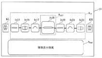
図2に、本実施形態に係る画面構成例を示す。イベント表示領域AIVに、被測定光ファイバ92上で連続する3以上のイベントIv18〜Iv24のアイコンが表示されている。各アイコンは、光線路を示す直線で接続されている。アイコンには、障害の種類に応じた図柄が付される。これにより、被測定光ファイバ92におけるイベントの発生順及び障害の分類を同時に表示する。イベント表示領域AIVのうちの特定領域AATT内に配置されているイベントIv21のアイコンは、注目イベントとして、拡大表示されている。FIG. 2 shows an example of the screen configuration according to the present embodiment. In the event display areaA IV, 3 or more events Iv18~Iv24 icons consecutive on the measured
各アイコンは、敷設状態の合否によって定められる色又は模様が付されていてもよい。例えば、イベントが合格のときはアイコンの背景又は外縁を青又は緑で表示し、イベントが不合格のときはアイコンの背景又は外縁を赤で表示する。このように、イベントの合否によって色分けすることで、イベント表示領域AIVに表示するアイコンを小さくした場合であっても、不合格のイベントが存在することを明示することができる。Each icon may have a color or pattern determined by acceptance or rejection of the laying state. For example, when the event is passed, the background or outer edge of the icon is displayed in blue or green, and when the event is failed, the background or outer edge of the icon is displayed in red. In this way, by color coding the acceptance of an event, even when the small icon to be displayed in the event display area AIV, it is possible to demonstrate that the failure of the event exists.
表示部13は、情報表示領域AINFに、注目イベントの情報を表示する。例えば、注目イベントがイベントIv21の場合、CPU12は、被測定光ファイバ92の入射端又は遠端からイベントIv21までの距離、イベントIv21での反射減衰量、イベントIv21での損失値、OTDR波形におけるイベントIv21での拡大波形、イベントIv21の合否、の少なくともいずれかを情報表示領域AINFに表示する。The
表示部13は、情報表示領域AINFに、被測定光ファイバ92全体での合否を表示することが好ましい。また、表示部13は、情報表示領域AINFに、被測定光ファイバ92全体での損失値を表示することが好ましい。被測定光ファイバ92全体での損失値及びイベントIv21での損失値の両方を表示することで、イベントIv21での損失値の寄与の度合いを把握することができる。The
操作検出部14は、イベント表示領域AIVにおけるスワイプ操作D1の操作量を検出する。すると、CPU12は、注目イベント変更部として機能し、スワイプ操作D1の操作量に従ってイベント表示領域AIVに表示するイベントのアイコンをスクロールさせる。このため、左から右にスワイプ操作D1を行うと、各イベントIv18〜Iv24が右に水平移動する。このとき、移動中に最も特定領域AATTに近いアイコンのイベントが常に注目イベントとなる。これにより、図3に示すように、移動後のイベントIv15〜Iv21のアイコンがイベント表示領域AIVに表示される。スワイプの加速度を感知し移動に慣性を持たせることも可能である。Operation detection unit 14 detects an operation amount of swipe D1 in the event display area AIV. Then,
ここで、イベントIv18のアイコンが特定領域AATTに移動するまでの間に、イベントIv20及びIv19のアイコンが順に特定領域AATTを通過する。このとき、イベントIv20及びIv19のアイコンについても、特定領域AATTを通過する際は、拡大表示される。このように、スワイプ操作D1によってイベントが特定領域AATTを通過する際、特定領域AATT内に表示されるイベントのアイコンを拡大表示することが好ましい。Here, while the icon of the event Iv18 moves to the specific area AATT , the icons of the events Iv20 and Iv19 sequentially pass through the specific area AATT . At this time, the icons of the events Iv20 and Iv19 are also enlarged when passing through the specific area AATT . As described above, when an event passes the specific area AATT by the swipe operation D 1, it is preferable to magnify and display the icon of the event displayed in the specific area AATT .
また、イベントIv20及びIv19のアイコンが順に特定領域AATTを通過するとき、CPU12は、注目イベント変更部として機能し、情報表示領域AINFに表示する情報を、特定領域AATTに位置するアイコンのイベントIv20及びIv19ごとに変化させる。このように、画面を指などで左右になぞるスワイプ操作により、アイコン列をスクロール可能にし、常に特定領域AATTのイベントを注目イベントとする。Further, when the icons of the events Iv20 and Iv19 sequentially pass through the specific area AATT , the
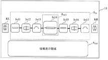
操作検出部14は、表示部13に表示されているタッチキーKR及びKLへのタップ操作を検出することが好ましい。タッチキーKRが1度タップされると、CPU12は、イベント表示領域AIVに表示するアイコンのイベントを左に移動する。図2の表示状態からタッチキーKRを1度タップすると、図4に示すように、イベントIv25〜Iv31のアイコンがイベント表示領域AIVに表示され、イベントIv28のアイコンが特定領域AATT内に配置される。タッチキーKLが1度タップされると、CPU12は、イベント表示領域AIVに表示するイベントのアイコンを右に移動する。図2の表示状態からタッチキーKLを1度タップすると、図5に示すように、イベントIv11〜Iv17のアイコンがイベント表示領域AIVに表示され、イベントIv14のアイコンが特定領域AATT内に配置される。なお、タッチキーKR及びKLは、1度のタップ操作でアイコン1個分の移動動作となるようにしてもよいことは言うまでもない。The operation detection unit 14 preferably detects a tap operation on the touch keys KR and KL displayed on the
操作検出部14は、イベント表示領域AIVにおけるピンチ操作及びストレッチ操作を検出することが好ましい。この場合、ピンチ操作に従って非注目イベントのアイコンを小さくし、ストレッチ操作に従って非注目イベントのアイコンを大きくする。Operation detection unit 14, it is preferable to detect the pinch operation and stretching operation in the event display area AIV. In this case, the icon of the non-attention event is made smaller according to the pinch operation, and the icon of the non-attention event is made larger according to the stretch operation.
以上説明したように、本実施形態は、スワイプ操作やタッチキーKR及びKLのタップ操作によって注目イベントを変更できるため、複数回の操作が必要だった注目イベントの変更を、1回の操作で可能にすることができる。これにより、本実施形態は、イベントの数が多くなった場合であっても、直感的な操作で注目イベントの変更が容易になるとともに、効率的な障害点の確認が可能な光パルス試験器91を提供することができる。 As described above, according to the present embodiment, the attention event can be changed by the swipe operation or the tap operation of the touch keys KR and KL. Therefore, the attention event change that required multiple operations can be performed by one operation. Can be Thus, according to the present embodiment, even when the number of events increases, it is possible to easily change the event of interest with an intuitive operation, and it is possible to efficiently check the failure point. 91 can be provided.
なお、特定領域AATTは、イベント表示領域AIVの任意の領域とすることが可能である。例えば、図2及び図3に示すようなイベント表示領域AIVの中央であってもよいし、イベント表示領域AIVの端であってもよい。The specific area AATT can be an arbitrary area of the event display area AIV . For example, it may be at the center of the event display area AIV as shown in FIGS. 2 and 3 or at the end of the event display area AIV .
また、イベント表示領域AIVに表示されるイベントのアイコンの数は3以上の任意の数とすることができる。例えば、イベント表示領域AIVに表示されるイベントのアイコンの数は、図2及び図3に示す7に限らず、8以上としてもよい。In addition, the number of icons of events displayed in the event display areaAIV can be any number of three or more. For example, the number of icons of events displayed in the event display areaAIV is not limited to 7 shown in FIGS. 2 and 3 and may be 8 or more.
また、図2及び図3のスワイプ操作例では、右方向へのスワイプ操作を示したが、左方向へのスワイプ操作の場合も、右方向へのスワイプ操作と同様に、各イベントIv18〜Iv24が左に水平移動し、移動中に最も特定領域AATTに近いアイコンのイベントが常に注目イベントとなる。2 and 3 show swipe operations in the right direction, but in the case of swipe operations in the left direction, each event Iv18 to Iv24 is similar to the swipe operation in the right direction. The event of the icon closest to the specific area AATT moving horizontally to the left and moving is always the attention event.
また、図2から図5ではイベント表示領域AIVに表示される各アイコンが画面の左右に配置されている例を示したが、本実施形態に係る発明はこれに限定されない。例えば、図6に示すように、各アイコンが画面の上下に配置されていてもよい。この場合、光線路が上下に接続されることになるため、アイコンの図柄は、光線路を示す直線に合わせた向きに回転させることが好ましい。Also, although an example in which the icons displayed in Figures 2 to 5 in the event display area AIV is located on the left and right of the screen, the invention according to the present embodiment is not limited thereto. For example, as shown in FIG. 6, each icon may be arranged at the top and bottom of the screen. In this case, since the light paths are connected vertically, it is preferable to rotate the icon pattern in a direction that matches the straight line indicating the light paths.
また、図2から図5ではイベント表示領域AIVに表示される各アイコンが一定間隔で配置されている例を示したが、本実施形態に係る発明はこれに限定されない。例えば、図7に示すように、特定領域AATT外においては非注目イベントを重ねて表示してもよい。Also, although an example in which the icons displayed in Figures 2 to 5 in the event display area AIV are arranged at regular intervals, the invention according to the present embodiment is not limited thereto. For example, as shown in FIG. 7, non-interest events may be displayed overlappingly outside the specific area AATT .
この場合、アイコン同士が重なる領域は、均一であってもよいが、均一でないことが好ましい。例えば、アイコン同士の重なりは、注目イベントから近いイベントのアイコンよりも注目イベントから遠いイベントの方が大きいことが好ましい。これにより、より多くのイベントのアイコンをイベント表示領域AIVに表示することができ、被測定光ファイバ92のイベント数の多少を一目で把握することができる。In this case, the area where the icons overlap may be uniform, but is preferably not uniform. For example, it is preferable that the overlap between the icons is larger in the event far from the attention event than in the icon of the event close to the attention event. As a result, icons of more events can be displayed in the event display areaAIV, and the number of events of the measured
また、図2から図5ではイベント表示領域AIVに表示される各アイコンが直線的に配置されている例を示したが、本実施形態に係る発明はこれに限定されない。特定領域AATT外においては非注目イベントを曲線的に配置してもよい。曲線は任意であるが、例えば、図8に示すように、円弧状とすることができる。これにより、より多くのイベントのアイコンをイベント表示領域AIVに表示することができる。Furthermore, each icon displayed in Figures 2 to 5 in the event display area AIV is an example that is linearly arranged, the invention according to the present embodiment is not limited thereto. Outside the specific area AATT , non-interesting events may be arranged in a curved manner. The curve is arbitrary, but can be, for example, an arc as shown in FIG. Thereby, icons of more events can be displayed in the event display areaAIV .
この場合、図8に示すように、特定領域AATT外においては非注目イベントを重ねて表示することが好ましい。アイコン同士が重なる領域は、均一であってもよいが、均一でないことが好ましい。例えば、アイコン同士の重なりは、注目イベントから近いイベントのアイコンよりも注目イベントから遠いイベントの方が大きいことが好ましい。In this case, as shown in FIG. 8, it is preferable to display non-interesting events overlappingly outside the specific area AATT . The area where the icons overlap may be uniform, but is preferably not uniform. For example, it is preferable that the overlap between the icons is larger in the event far from the attention event than in the icon of the event close to the attention event.
図8に示す画面構成では、イベント表示領域AIVに多くのイベントを表示することができる。このため、イベント表示領域AIVには被測定光ファイバ92の全イベントのアイコンがすべて表示されていてもよい。この場合、CPU12は、注目イベント変更部として機能する際に、スワイプ操作D1に従って、円形に配列されたアイコンが注目イベントを切り替えながら回転させる。In the screen configuration shown in FIG. 8, many events can be displayed in the event display areaAIV . For this reason, all the icons of all the events of the
(実施形態2)
図9に、本実施形態に係る画面構成例を示す。本実施形態では、操作検出部14が、実施形態1の機能に加え、さらに、イベント表示領域AIVに表示されているアイコン上でのタップ操作を検出する。すると、CPU12は、注目イベント変更部として機能し、タップ操作の検出されたアイコンを特定領域AATTに移動させる。Second Embodiment
FIG. 9 shows an example of the screen configuration according to the present embodiment. In the present embodiment, in addition to the function of the first embodiment, the operation detection unit 14 further detects a tap operation on an icon displayed in the event display areaAIV . Then, the
例えば、非注目イベントであるイベントIv18のアイコンが押下(タップ)されると、CPU12は、イベント表示領域AIVに表示するアイコンをスクロールさせ、イベントIv18のアイコンを特定領域AATTに移動させて注目イベントとする。このように、注目したいイベントをタップすることで、イベント表示領域AIV内の各イベントが瞬時に水平移動し、タップされたイベントが注目イベントとなる。これにより、図3に示すように、移動後のイベントIv15〜Iv21のアイコンがイベント表示領域AIVに表示される。For example, when the icon of the event Iv18 which is a non-attention event is pressed (taped), the
このとき、スワイプ操作D1と同様に、イベントIv20及びIv19のアイコンが特定領域AATTを通過する際、イベントIv20及びIv19を注目イベントとすることが好ましい。At this time, similarly to the swipe operation D1, when the icons of the events Iv20 and Iv19 pass the specific area AATT , it is preferable to set the events Iv20 and Iv19 as the attention event.
(実施形態3)
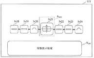
CPU12は、OTDR波形を用いてイベントを検出する際、イベントの発生地点を検出する。表示部13が、被測定光ファイバ92全体における各イベントの発生地点を発生地点表示領域APに表示する。(Embodiment 3)
When detecting an event using the OTDR waveform, the
図10に、本実施形態に係る画面構成例を示す。本実施形態では、一例として、イベントIv18〜Iv24の発生地点P18〜P24が発生地点表示領域APに表示される場合を示す。例えば、発生地点表示領域APは、被測定光ファイバ92全体を示す直線を有し、当該直線上のうちの被測定光ファイバ92全体に対するイベントの発生地点P18〜P24を表示する。FIG. 10 shows an example of the screen configuration according to the present embodiment. In the present embodiment, as an example, a case where occurrence point P18~P24 event Iv18~Iv24 is displayed on occurrence point display areaA P. For example, occurrence point display area AP has a straight line showing the entire measured
ここで、発生地点P18〜P24は、敷設状態の合否によって定められる色又は模様が付されていることが好ましい。これにより、敷設状態が不合格となっているイベントの発生地点を速やかに特定することができる。 Here, it is preferable that the generation | occurrence | production point P18-P24 is provided with the color or pattern defined by the pass / fail of a laying state. In this way, it is possible to quickly identify the point of occurrence of an event whose installation status has been rejected.
本実施形態では、操作検出部14は、実施形態1の機能に加え、さらに、表示部13に表示されている発生地点P18〜P24上でのタップ操作を検出する。例えば、発生地点P18がタップされたとする。この場合、CPU12は、注目イベント変更部として機能し、イベント表示領域AIVに表示するアイコンをスクロールさせ、タップ操作が検出された発生地点P18のイベントIv18のアイコンを特定領域AATTに移動させる。これにより、図3に示すように、移動後のイベントIv15〜Iv21のアイコンがイベント表示領域AIVに表示される。In the present embodiment, the operation detection unit 14 further detects a tap operation on the occurrence points P18 to P24 displayed on the
このように、本実施形態は、注目したいイベントの発生地点をタップすることで、イベント表示領域AIV内の各イベントが瞬時に水平移動し、タップされたイベントが注目イベントとなる。このとき、スワイプ操作D1と同様に、イベントIv20及びIv19のアイコンが特定領域AATTを通過する際、イベントIv20及びIv19を注目イベントとすることが好ましい。As described above, according to the present embodiment, each event in the event display area AIV is horizontally moved instantaneously by tapping the occurrence point of the event to be focused, and the tapped event becomes the focused event. At this time, similarly to the swipe operation D1, when the icons of the events Iv20 and Iv19 pass the specific area AATT , it is preferable to set the events Iv20 and Iv19 as the attention event.
(実施形態4)
実施形態1から実施形態3では、注目イベントが1地点のみであったが、本実施形態では注目イベントが2地点である。本実施形態に係る光パルス試験器91は、イベント表示領域AIVでのタップ操作に応じて表示部13の表示を変更する。(Embodiment 4)
In the first to third embodiments, the focused event is only one point, but in the present embodiment, the focused event is two points. The
本実施形態に係る光パルス試験器91は、図1に示す構成を用いることができる。実施形態1及び2に係る光パルス試験器91に本実施形態を適用する場合、図2〜図9に示す画面構成を用いることができる。実施形態3に係る光パルス試験器91に本実施形態を適用する場合、図10に示す画面構成を用いることができる。 The
操作検出部14は、異なる2つのイベントのアイコン上でのタップ操作を検出する。例えば、イベントIv18及びIv20のアイコン上でタップ操作が行われる。すると、表示部13は、タップ操作が検出されたイベントIv18及びIn20のアイコンを強調表示する。強調表示は、例えば、アイコンを拡大してもよいし、他のアイコンとは異なる色にしてもよい。 The operation detection unit 14 detects a tap operation on icons of two different events. For example, a tap operation is performed on the icons of the events Iv18 and Iv20. Then, the
CPU12は、算出部として機能し、タップ操作が検出されたアイコンのイベントIv18及びIn20の距離及び損失を算出する。表示部13は、CPU12の算出した距離及び損失を情報表示領域AINFに表示する。The
以上説明したように、本実施形態は、注目イベントが1地点である実施形態1から実施形態3に加え、さらに注目イベントを2地点とした場合の表示を行うことができる。 As described above, in the present embodiment, in addition to the first to third embodiments in which the focused event is one point, it is possible to perform display in the case where the focused event is two points.
ただし、実施形態2に本実施形態を適用する際は、注目イベントが1地点であるか2地点であるかを操作検出部14が識別できるようにする。例えば、1つのアイコンのみがタップされた場合、操作検出部14は注目イベントが1地点であると判定し、2つのアイコンが同時にタップされた場合、操作検出部14は注目イベントが2地点であると判定する。 However, when the present embodiment is applied to the second embodiment, the operation detection unit 14 can identify whether the focused event is one point or two points. For example, when only one icon is tapped, the operation detection unit 14 determines that the attention event is at one point, and when two icons are simultaneously tapped, the operation detection unit 14 indicates two attention events. It is determined that
(実施形態5)
本実施形態に係る光パルス試験器91は、実施形態4と同様に、注目イベントが2地点である。本実施形態に係る光パルス試験器91は、発生地点表示領域APでのタップ操作に応じて表示部13の表示を変更する。Embodiment 5
As in the fourth embodiment, the
本実施形態に係る光パルス試験器91は、図1に示す構成を用いることができる。実施形態1から実施形態4に係る光パルス試験器91に本実施形態を適用する場合、図10に示す画面構成を用いることができる。 The
本実施形態では、操作検出部14は、発生地点表示領域APにおける異なる2つの発生地点上でのタップ操作を検出する。例えば、発生地点P18及びP20上でタップ操作が行われる。すると、表示部13は、タップ操作が検出された発生地点18及びP20を強調表示する。強調表示は、例えば、図10に示すP18のように発生地点を示す印を拡大してもよいし、発生地点を示す印の色を変えてもよい。In the present embodiment, the operation detection unit 14 detects the tap operation on two different occurrence point in generating point display area AP. For example, the tap operation is performed on the occurrence points P18 and P20. Then, the
CPU12は、算出部として機能し、タップ操作が検出された発生地点18及びP20間の距離及び損失を算出する。表示部13は、CPU12の算出した距離及び損失を情報表示領域AINFに表示する。The
以上説明したように、本実施形態は、注目イベントが1地点である実施形態1から実施形態3に加え、さらに注目イベントを2地点とした場合の表示を行うことができる。ただし、実施形態3に本実施形態を適用する際は、注目イベントが1地点であるか2地点であるかを操作検出部14が識別できるようにする。 As described above, in the present embodiment, in addition to the first to third embodiments in which the focused event is one point, it is possible to perform display in the case where the focused event is two points. However, when the present embodiment is applied to the third embodiment, the operation detection unit 14 can identify whether the focused event is one point or two points.
例えば、1つの発生地点のみがタップされた場合、操作検出部14は注目イベントが1地点であると判定し、2つの発生地点が同時にタップされた場合、操作検出部14は注目イベントが2地点であると判定する。 For example, when only one occurrence point is tapped, the operation detection unit 14 determines that the attention event is one point, and when two occurrence points are simultaneously tapped, the operation detection unit 14 indicates two attention events It is determined that
本発明は情報通信産業に適用することができる。 The present invention can be applied to the information communication industry.
11:OTDR波形測定部
12:CPU
13、113:表示部
14:操作検出部
91:光パルス試験器
92:被測定光ファイバ11: OTDR waveform measurement unit 12: CPU
13, 113: Display unit 14: Operation detection unit 91: Optical pulse tester 92: Optical fiber to be measured
Claims (8)
Translated fromJapanese前記戻り光の強度が変化するイベントを検出するイベント検出部と、
前記イベントを示す複数個のアイコンをイベント表示領域に表示し、前記イベント表示領域内の特定領域に位置するアイコンが示すイベントの情報を情報表示領域に表示する表示部と、
前記イベント表示領域におけるスワイプ操作を検出する操作検出部と、
前記操作検出部が検出したスワイプ操作で定められる方向に前記イベント表示領域に表示するアイコンを移動させるとともに、当該スワイプ操作に加えての操作なく前記特定領域に位置するアイコンが示すイベントごとに前記情報表示領域に表示する情報を変化させる注目イベント変更部と、
を備え、
前記操作検出部は、加速度を持った前記スワイプ操作を検出し、当該検出をした場合には、前記アイコンの前記移動に慣性を持たせる、
光パルス試験器。A measurement unit which makes an optical pulse incident on an optical fiber to be measured, and receives an optical pulse reflected or scattered by the optical fiber to be measured;
An event detection unit that detects an event in which the intensity of the return light changes;
A display unit which displays a plurality of icons indicating the event in an event display area, and displays information of an event indicated by an icon located in a specific area in the event display area in an information display area;
An operation detection unit that detects a swipe operation in the event display area;
Wherein each event indicating the icon located in the specific areawithout the operation of the operation detecting unit isRutotomoni moves the icon to be displayed in the event display area in the direction defined by the swipe operation detected,in addition to the swipe operation An attention event change unit that changes information displayed in the information display area;
Equipped with
The operation detection unit detects the swipe operation having an acceleration, and when the detection is performed, gives inertia to the movement of the icon.
Optical pulse tester.
前記注目イベント変更部は、前記イベント表示領域に表示するアイコンを移動させ、前記タップ操作の検出された前記アイコンを前記特定領域に移動させる、
請求項1に記載の光パルス試験器。The operation detection unit detects a tap operation on the icon,
The noted event changing unit moves an icon to be displayed in the event display area, and moves the detected icon of the tap operation to the specific area.
The light pulse tester according to claim 1.
前記操作検出部は、前記発生地点表示領域における前記発生地点上でのタップ操作を検出し、
前記注目イベント変更部は、前記イベント表示領域に表示するアイコンを移動させ、前記タップ操作が検出された前記発生地点のイベントの前記アイコンを前記特定領域に移動させる、
請求項1又は2に記載の光パルス試験器。The display unit displays the occurrence point of each event in the entire measured optical fiber in the occurrence point display area;
The operation detection unit detects a tap operation on the occurrence point in the occurrence point display area,
The noted event changing unit moves an icon to be displayed in the event display area, and moves the icon of the event at the occurrence point at which the tap operation is detected to the specific area.
An optical pulse tester according to claim 1 or 2.
前記タップ操作が検出された前記アイコンのイベント間の距離及び損失を算出する算出部をさらに備え、
前記表示部は、前記タップ操作が検出された前記アイコンを強調表示し、前記算出部の算出した距離及び損失を前記情報表示領域に表示する、
請求項1から3のいずれかに記載の光パルス試験器。The operation detection unit detects a tap operation on icons of two different events.
It further comprises a calculation unit for calculating the distance between the events of the icons for which the tap operation has been detected and a loss,
The display unit highlights the icon for which the tap operation has been detected, and displays the distance and loss calculated by the calculation unit in the information display area.
The optical pulse tester according to any one of claims 1 to 3.
前記操作検出部は、前記発生地点表示領域における異なる2つの前記発生地点上でのタップ操作を検出し、
前記タップ操作が検出された前記発生地点間の距離及び損失を算出する算出部をさらに備え、
前記表示部は、前記タップ操作が検出された前記発生地点を強調表示し、前記算出部の算出した距離及び損失を前記情報表示領域に表示する、
請求項1から4のいずれかに記載の光パルス試験器。The display unit displays the occurrence point of each event in the entire measured optical fiber in the occurrence point display area;
The operation detection unit detects tap operations on two different occurrence points in the occurrence point display area,
It further comprises a calculation unit for calculating the distance between the occurrence points where the tap operation has been detected and a loss,
The display unit highlights the occurrence point at which the tap operation is detected, and displays the distance and loss calculated by the calculation unit in the information display area.
The optical pulse tester according to any one of claims 1 to 4.
請求項1から5のいずれかに記載の光パルス試験器。The display unit displays a plurality of icons indicating the events in the order of occurrence of the events in the measured optical fiber.
The optical pulse tester according to any one of claims 1 to 5.
請求項1から6のいずれかに記載の光パルス試験器。The display unit displays an icon of an event located in the specific area more enlarged than an icon of an event located outside the specific area.
The light pulse tester according to any one of claims 1 to 6.
前記測定手順の測定結果を用いて、前記戻り光の強度が変化するイベントを検出するイベント検出手順と、
前記イベントを示す複数個のアイコンを表示部のイベント表示領域に表示し、前記イベント表示領域内の特定領域に位置するイベントの情報を前記表示部の情報表示領域に表示する表示手順と、
前記イベント表示領域におけるスワイプ操作を検出すると、前記スワイプ操作で定められる方向に前記イベント表示領域に表示するアイコンを移動させるとともに、当該スワイプ操作に加えての操作なく前記特定領域に位置するアイコンが示すイベントごとに前記情報表示領域に表示する情報を変化させる注目イベント変更手順と、
を有し、
前記注目イベント変更手順において、加速度を持った前記スワイプ操作を検出し、当該検出をした場合には、前記アイコンの前記移動に慣性を持たせる、
光パルス試験器の表示方法。A measurement procedure in which an optical pulse is incident on a measured optical fiber, and the optical pulse receives return light reflected or scattered by the optical fiber to be measured;
An event detection procedure for detecting an event in which the intensity of the return light changes using the measurement result of the measurement procedure;
A display procedure for displaying a plurality of icons indicating the event in an event display area of a display unit, and displaying information on an event located in a specific area in the event display area in an information display area of the display unit;
Upon detecting a swipe operation in the event display area, the swipe operation in moving anicon in the direction defined displayed on the event display areaRutotomoni,an icon positioned in the specific areawithout the operation in addition to the swipe operation An attention event change procedure for changing information displayed in the information display area for eachindicated event;
Have
In the noted event change procedure, the swipe operation with acceleration is detected, and when the detection is performed, the movement of the icon is given inertia.
Optical pulse tester display method.
Priority Applications (3)
| Application Number | Priority Date | Filing Date | Title |
|---|---|---|---|
| JP2015239753AJP6514629B2 (en) | 2015-12-08 | 2015-12-08 | Optical pulse tester and display method of optical pulse tester |
| US15/363,264US10067665B2 (en) | 2015-12-08 | 2016-11-29 | Optical time domain reflectometer and display method of optical time domain reflectometer |
| JP2019029226AJP6937788B2 (en) | 2015-12-08 | 2019-02-21 | Display method of optical pulse tester and optical pulse tester |
Applications Claiming Priority (1)
| Application Number | Priority Date | Filing Date | Title |
|---|---|---|---|
| JP2015239753AJP6514629B2 (en) | 2015-12-08 | 2015-12-08 | Optical pulse tester and display method of optical pulse tester |
Related Child Applications (1)
| Application Number | Title | Priority Date | Filing Date |
|---|---|---|---|
| JP2019029226ADivisionJP6937788B2 (en) | 2015-12-08 | 2019-02-21 | Display method of optical pulse tester and optical pulse tester |
Publications (2)
| Publication Number | Publication Date |
|---|---|
| JP2017106784A JP2017106784A (en) | 2017-06-15 |
| JP6514629B2true JP6514629B2 (en) | 2019-05-15 |
Family
ID=58798778
Family Applications (1)
| Application Number | Title | Priority Date | Filing Date |
|---|---|---|---|
| JP2015239753AActiveJP6514629B2 (en) | 2015-12-08 | 2015-12-08 | Optical pulse tester and display method of optical pulse tester |
Country Status (2)
| Country | Link |
|---|---|
| US (1) | US10067665B2 (en) |
| JP (1) | JP6514629B2 (en) |
Families Citing this family (2)
| Publication number | Priority date | Publication date | Assignee | Title |
|---|---|---|---|---|
| US10365719B2 (en)* | 2017-07-26 | 2019-07-30 | Google Llc | Haptic feedback of user interface scrolling with synchronized visual animation components |
| CN110187238A (en)* | 2019-06-14 | 2019-08-30 | 国网北京市电力公司 | A kind of intrinsic frequency range-measurement system and method based on temporal signatures |
Family Cites Families (14)
| Publication number | Priority date | Publication date | Assignee | Title |
|---|---|---|---|---|
| US5528356A (en)* | 1995-03-20 | 1996-06-18 | Tektronix, Inc. | Apparatus and method for displaying multiple sample spacing waveform segments |
| US7057401B2 (en)* | 2004-03-23 | 2006-06-06 | Pass & Seymour, Inc. | Electrical wiring inspection system |
| US7016024B2 (en)* | 2004-05-18 | 2006-03-21 | Net Test (New York) Inc. | Accuracy automated optical time domain reflectometry optical return loss measurements using a “Smart” Test Fiber Module |
| US7206703B1 (en)* | 2005-05-02 | 2007-04-17 | Advanced Micro Devices, Inc. | System and method for testing packaged devices using time domain reflectometry |
| JP5243870B2 (en)* | 2008-07-15 | 2013-07-24 | 任天堂株式会社 | Information processing system, information processing apparatus, and information processing program |
| US8736582B2 (en)* | 2009-11-29 | 2014-05-27 | Kihong (Joshua) Kim | Time domain reflectometer touch screen sensor |
| US9212969B2 (en)* | 2011-02-07 | 2015-12-15 | Piotr Anatolij Levin | Optical time domain reflectometer user interface |
| US9134197B2 (en)* | 2013-01-15 | 2015-09-15 | Exfo Inc. | Bi-directional multi-pulsewidth optical time-domain reflectometer |
| US8958060B2 (en)* | 2013-02-21 | 2015-02-17 | Verizon Patent And Licensing Inc. | Optical fiber mechanical bend stress test system with optical time-domain reflectometer |
| US10284632B2 (en)* | 2013-03-29 | 2019-05-07 | WOW Insites LLC | Electronic testing device |
| JP2014215900A (en)* | 2013-04-26 | 2014-11-17 | パイオニア株式会社 | Operation input device, electronic device, and input control method |
| JP2015203866A (en)* | 2014-04-14 | 2015-11-16 | 知紘 松野 | program |
| US9594147B2 (en)* | 2014-10-03 | 2017-03-14 | Apple Inc. | Wireless electronic device with calibrated reflectometer |
| US10161829B2 (en)* | 2015-06-04 | 2018-12-25 | Fluke Corporation | System and method for certification of physical parameters of communication links |
- 2015
- 2015-12-08JPJP2015239753Apatent/JP6514629B2/enactiveActive
- 2016
- 2016-11-29USUS15/363,264patent/US10067665B2/enactiveActive
Also Published As
| Publication number | Publication date |
|---|---|
| US10067665B2 (en) | 2018-09-04 |
| US20170160894A1 (en) | 2017-06-08 |
| JP2017106784A (en) | 2017-06-15 |
Similar Documents
| Publication | Publication Date | Title |
|---|---|---|
| US8266278B2 (en) | Apparatus and method for visualizing network state by using geographic information | |
| KR20120088503A (en) | Method of tracing touch paths for a multi-touch panel | |
| US20110252405A1 (en) | Detecting user interface defects in a software application | |
| EP2849039A1 (en) | Method, device, and mobile terminal for detecting capacitive touch screen | |
| CN109613381A (en) | Short-circuit detecting module | |
| JP6514629B2 (en) | Optical pulse tester and display method of optical pulse tester | |
| CN103052921A (en) | Method and computer program products for enabling supervision and control of a technical system | |
| CN110932894A (en) | Network fault positioning method and device of cloud storage system and electronic equipment | |
| JP6969320B2 (en) | Monitoring status display device, monitoring status display method, and monitoring status display program | |
| KR20160004992A (en) | Alarm-position display apparatus and alarm-position display method | |
| CN101454681A (en) | Signal-under-test analyzing device | |
| WO2019102757A1 (en) | Monitoring state display device, monitoring state display method, and monitoring state display program | |
| JP2019113561A (en) | Optical pulse tester and display method for optical pulse tester | |
| TWI632497B (en) | Touch sensitive processing apparatus, electronic system and method thereof for detecting defects of touch panel | |
| US10152039B2 (en) | Method and apparatus for the display of multiple errors on a human-machine interface | |
| CN104618151A (en) | GIS technology-based ONU equipment fault location method for EPON network | |
| CN109980789B (en) | State detection method, device, equipment and medium of DC control and protection system | |
| JP5542624B2 (en) | Plant monitoring device | |
| JP2016085496A (en) | Apparatus and method for detecting abnormal signs of computer system | |
| JP5580862B2 (en) | Error rate measurement display apparatus and method | |
| KR101094129B1 (en) | Command execution method and command execution device | |
| KR101620319B1 (en) | Database Monitoring Apparatus and Method, Database Monitoring System Using the Same | |
| JP2015082164A (en) | Touch panel device and operation detection method | |
| JP6736319B2 (en) | Alarm display system and alarm display method | |
| JP2017072452A (en) | Display device, measuring device, display method, and program |
Legal Events
| Date | Code | Title | Description |
|---|---|---|---|
| A621 | Written request for application examination | Free format text:JAPANESE INTERMEDIATE CODE: A621 Effective date:20170725 | |
| A977 | Report on retrieval | Free format text:JAPANESE INTERMEDIATE CODE: A971007 Effective date:20180524 | |
| A131 | Notification of reasons for refusal | Free format text:JAPANESE INTERMEDIATE CODE: A131 Effective date:20180605 | |
| A601 | Written request for extension of time | Free format text:JAPANESE INTERMEDIATE CODE: A601 Effective date:20180717 | |
| A521 | Request for written amendment filed | Free format text:JAPANESE INTERMEDIATE CODE: A523 Effective date:20180928 | |
| A131 | Notification of reasons for refusal | Free format text:JAPANESE INTERMEDIATE CODE: A131 Effective date:20181113 | |
| A601 | Written request for extension of time | Free format text:JAPANESE INTERMEDIATE CODE: A601 Effective date:20190110 | |
| A521 | Request for written amendment filed | Free format text:JAPANESE INTERMEDIATE CODE: A523 Effective date:20190228 | |
| TRDD | Decision of grant or rejection written | ||
| A01 | Written decision to grant a patent or to grant a registration (utility model) | Free format text:JAPANESE INTERMEDIATE CODE: A01 Effective date:20190402 | |
| A61 | First payment of annual fees (during grant procedure) | Free format text:JAPANESE INTERMEDIATE CODE: A61 Effective date:20190412 | |
| R150 | Certificate of patent or registration of utility model | Ref document number:6514629 Country of ref document:JP Free format text:JAPANESE INTERMEDIATE CODE: R150 | |
| R250 | Receipt of annual fees | Free format text:JAPANESE INTERMEDIATE CODE: R250 | |
| R250 | Receipt of annual fees | Free format text:JAPANESE INTERMEDIATE CODE: R250 | |
| R250 | Receipt of annual fees | Free format text:JAPANESE INTERMEDIATE CODE: R250 | |
| R250 | Receipt of annual fees | Free format text:JAPANESE INTERMEDIATE CODE: R250 |