JP6514480B2 - Ink filler - Google Patents
Ink fillerDownload PDFInfo
- Publication number
- JP6514480B2 JP6514480B2JP2014212004AJP2014212004AJP6514480B2JP 6514480 B2JP6514480 B2JP 6514480B2JP 2014212004 AJP2014212004 AJP 2014212004AJP 2014212004 AJP2014212004 AJP 2014212004AJP 6514480 B2JP6514480 B2JP 6514480B2
- Authority
- JP
- Japan
- Prior art keywords
- ink
- pen
- hole
- nozzle
- pen tip
- Prior art date
- Legal status (The legal status is an assumption and is not a legal conclusion. Google has not performed a legal analysis and makes no representation as to the accuracy of the status listed.)
- Active
Links
- 239000000945fillerSubstances0.000titleclaimsdescription34
- 239000007788liquidSubstances0.000claimsdescription15
- 230000002093peripheral effectEffects0.000description18
- 230000003020moisturizing effectEffects0.000description7
- 238000003780insertionMethods0.000description5
- 230000037431insertionEffects0.000description5
- 229920000742CottonPolymers0.000description2
- 239000002657fibrous materialSubstances0.000description2
- 239000004745nonwoven fabricSubstances0.000description2
- 230000002745absorbentEffects0.000description1
- 239000002250absorbentSubstances0.000description1
- 210000001217buttockAnatomy0.000description1
- 239000011248coating agentSubstances0.000description1
- 238000000576coating methodMethods0.000description1
- 239000002537cosmeticSubstances0.000description1
- 230000007423decreaseEffects0.000description1
- 238000001035dryingMethods0.000description1
- 230000000694effectsEffects0.000description1
- -1feltSubstances0.000description1
- 230000014759maintenance of locationEffects0.000description1
- 238000000465mouldingMethods0.000description1
- 238000007789sealingMethods0.000description1
Images


Classifications
- B—PERFORMING OPERATIONS; TRANSPORTING
- B43—WRITING OR DRAWING IMPLEMENTS; BUREAU ACCESSORIES
- B43K—IMPLEMENTS FOR WRITING OR DRAWING
- B43K11/00—Filling devices
- B—PERFORMING OPERATIONS; TRANSPORTING
- B43—WRITING OR DRAWING IMPLEMENTS; BUREAU ACCESSORIES
- B43K—IMPLEMENTS FOR WRITING OR DRAWING
- B43K5/00—Pens with ink reservoirs in holders, e.g. fountain-pens
- B43K5/18—Arrangements for feeding the ink to the nibs
- B43K5/1818—Mechanical feeding means, e.g. valves; Pumps
- B43K5/1827—Valves
- B43K5/1836—Valves automatically closing
- B43K5/1845—Valves automatically closing opened by actuation of the writing point
- B—PERFORMING OPERATIONS; TRANSPORTING
- B43—WRITING OR DRAWING IMPLEMENTS; BUREAU ACCESSORIES
- B43K—IMPLEMENTS FOR WRITING OR DRAWING
- B43K8/00—Pens with writing-points other than nibs or balls
- B43K8/02—Pens with writing-points other than nibs or balls with writing-points comprising fibres, felt, or similar porous or capillary material
- B43K8/03—Ink reservoirs; Ink cartridges
- B—PERFORMING OPERATIONS; TRANSPORTING
- B43—WRITING OR DRAWING IMPLEMENTS; BUREAU ACCESSORIES
- B43K—IMPLEMENTS FOR WRITING OR DRAWING
- B43K8/00—Pens with writing-points other than nibs or balls
- B43K8/02—Pens with writing-points other than nibs or balls with writing-points comprising fibres, felt, or similar porous or capillary material
- B43K8/04—Arrangements for feeding ink to writing-points
Landscapes
- Engineering & Computer Science (AREA)
- Mechanical Engineering (AREA)
- Pens And Brushes (AREA)
Description
Translated fromJapanese本発明は、液状のインクを貯留するインク貯留部を有するペンに対してインクを充填するためのインク充填具に関する。 The present invention relates to an ink filler for filling an ink into a pen having an ink reservoir for storing liquid ink.
従来から、筆記具や化粧具等として用いられるペンには、種々タイプのものがあり、その一つとして、液状のインクを貯留するインク貯留部と、インクを含浸可能なペン先部であって、棒状に成形されたペン先部と、ペン先部を軸心方向に移動可能に挿入する貫通孔を有するホルダー部と、ペン先部が軸心方向に押圧されることで開弁する弁機構であって、開弁状態でインク貯留部からペン先部に向けてインクを流通させる弁機構とを備えたものがある。 Conventionally, there are various types of pens used as a writing instrument, a cosmetic tool, etc. One of them is an ink storage section for storing liquid ink, and a pen point section capable of impregnating the ink, A holder portion having a rod-shaped pen tip portion, a through hole for inserting the pen tip portion movably in the axial direction, and a valve mechanism that opens when the pen tip portion is pressed in the axial direction In some cases, there is provided a valve mechanism for circulating the ink from the ink storage portion toward the pen tip portion in an open state.
かかるペンは、ペン先部をインクの塗布対象に接触させることで、ペン先部に含浸されたインクを塗布対象に塗布できるようになっている。そして、この種のペンは、ペン先部のインクの含浸量が少なくなると、ペン先部を押圧することで弁機構を開弁させ、インク貯留部内のインクをペン先部に対して供給するようになっている。これにより、この種のペンは、必要に応じてペン先部をインクで潤沢にでき、筆記等を良好に行えるようになっている(例えば、特許文献1参照)。 Such a pen can apply the ink impregnated in the pen tip to the application target by bringing the pen tip into contact with the application target of the ink. The pen of this type opens the valve mechanism by pressing the pen tip when the amount of ink impregnated in the pen tip decreases, so that the ink in the ink storage part is supplied to the pen tip. It has become. As a result, this kind of pen can make the pen tip part rich with ink as needed, and can perform writing etc. well (see, for example, Patent Document 1).
ところで、この種のペンは、インク貯留部のインクが無くなると、ペン先部や弁機構が未だ使用可能な状態であるにも拘わらず、廃棄されるのが一般的である。 By the way, this type of pen is generally disposed of when the ink in the ink reservoir is exhausted, although the pen tip and the valve mechanism are still usable.
このような現状において、インク貯留部にインクを供給することで、再利用可能とすることが要求されている。特に、長期に亘って使用したペンは、使用者の癖が付き、継続して使用することが望まれている。 Under such current circumstances, it is required to be reusable by supplying ink to the ink storage section. In particular, pens that have been used for a long time have a habit of the user and are desired to be used continuously.
そこで、本発明は、使用済みのペンを再使用可能な状態にすることのできるインク充填具を提供することを課題とする。 Then, this invention makes it a subject to provide the ink filling tool which can make the used pen into the state which can be reused.
本発明に係るインク充填具は、液状のインクを貯留するインク貯留部と、インクを含浸可能なペン先部であって、棒状に成形されたペン先部と、ペン先部が軸心方向に移動可能に挿入された貫通孔を有するホルダー部と、ペン先部とインク貯留部との間に介設された弁機構であって、ペン先部によって押圧されることで開弁し、インク貯留部とペン先部とを繋ぐ連通路を開放させる弁機構とを備えたペンに対してペン先部をホルダー部から抜き取った状態でインクを補充するためのインク充填具であって、液状のインクを貯留可能な内部空間を有するインクタンク部と、インクタンク部の内部空間と連通する内孔を有する筒状のノズル部であって、前記貫通孔に挿入可能なノズル部と、ノズル部を包囲した環状のガイド部であって、前記ペンのホルダー部に外嵌可能なガイド部と、を備え、ノズル部は、貫通孔に挿入された状態で弁機構を押圧操作可能に構成されるとともに、自身の軸心と直交する方向で内孔と外部とを連通させたインク流通部を有することを特徴とする。
The ink filling tool according to the present invention includes an ink storage portion for storing liquid ink, a pen tip portion capable of impregnating the ink, and a pen tip portion formed in a rod shape and a pen tip portion in the axial direction. A holder unit having a movably inserted through hole, and a valve mechanism interposed between a pen tip and an ink reservoir, which is opened by being pressed by the pen tip, and the ink reservoir An ink filling tool for refilling ink ina state where a pen tip is removed from a holder with respect to a pen having a valve mechanism for opening a communication passage connecting the head and the pen tip, which is a liquid ink And an annular nozzle portion having an inner hole communicating with the inner space of the ink tank portion, the nozzle portion being insertable into the through hole,and surrounding the nozzle portion. Annular guide portion, the pen And an external fitting can guide portion to the holder portion, the nozzle portion while being configured a valve mechanism pressing operably while being inserted into the through hole, an inner hole in a direction perpendicular to its axis It is characterized in that it has an ink circulation portion communicating with the outside.
上記構成のインク充填具によれば、インクの充填の対象となるペンのペン先部をホルダー部(貫通孔)から抜き取った上で、ノズル部がペンのホルダー部における貫通孔に挿入されると、ノズル部がペンの弁機構に到達する。 According to the ink filling tool of the above configuration, after the pen point portion of the pen to be filled with the ink is removed from the holder portion (through hole), the nozzle portion is inserted into the through hole in the holder portion of the pen , And the nozzle portion reaches the valve mechanism of the pen.
そして、インク充填具全体がペン側に押されると、ノズル部が弁機構を押圧操作し、弁機構を開弁させる。そうすると、インクタンク部の内部空間は、ホルダー部の貫通孔内にあるノズル部の内孔、インク流通部、及び開放状態にある連通路を介してインク貯留部の内部空間と連通した状態となる。 Then, when the entire ink filler is pushed to the pen side, the nozzle portion presses the valve mechanism to open the valve mechanism. Then, the internal space of the ink tank portion communicates with the internal space of the ink storage portion through the inner hole of the nozzle portion in the through hole of the holder portion, the ink circulation portion, and the communication passage in the open state. .
より具体的に説明すると、ノズル部の内孔がインクタンク部から真っ直ぐ延びた上でノズル部の先端部で閉塞した状態で形成されたり、ノズル部の内孔がインクタンク部から真っ直ぐ延びた上でノズル部の先端で開放して形成され、弁機構に対する押圧操作に伴って閉ざされるように形成されたりすると、インクの流路が遮断されてしまう。 More specifically, the inner hole of the nozzle portion extends straight from the ink tank portion and is closed at the tip of the nozzle portion, or the inner hole of the nozzle portion extends straight from the ink tank portion. If it is formed open at the tip of the nozzle portion and is formed so as to be closed along with the pressing operation on the valve mechanism, the ink flow path is blocked.
しかし、上記構成のインク充填具のノズル部は、自身の軸心と直交する方向で内孔と外部とを連通させたインク流通部を有するため、ノズル部の先端と異なる位置にあるインク流通部を介してノズル部の内孔と開放状態の連通路とが連通し、結果的にインクタンク部とインク貯留部とが連通する。 However, since the nozzle portion of the ink filler having the above configuration has the ink circulation portion communicating the inner hole with the outside in the direction orthogonal to the axis of itself, the ink circulation portion is at a position different from the tip of the nozzle portion As a result, the inner hole of the nozzle portion and the open communication passage communicate with each other, and as a result, the ink tank portion and the ink storage portion communicate with each other.
これにより、インク充填具は、インクタンク部内のインクを、ノズル部の内孔、インク流通部、及び連通路を経由させてインク貯留部に流入させることができる。 Thus, the ink filler can cause the ink in the ink tank portion to flow into the ink storage portion via the inner hole of the nozzle portion, the ink circulation portion, and the communication passage.
そして、ペンのインク貯留部にインクが必要量供給されると、ノズル部をホルダー部(貫通孔)から抜き取るようにインク充填具全体を移動させる。そうすると、弁機構に対するノズル部の押圧操作が解除される。その結果、弁機構内の連通路が閉塞されるため、インク貯留部内のインクの漏洩が防止される。そして、ホルダー部(貫通孔)にペン先部が挿入されることで、インク切れであったペンが再使用可能な状態となる。 Then, when the necessary amount of ink is supplied to the ink storage portion of the pen, the entire ink filling tool is moved so as to extract the nozzle portion from the holder portion (through hole). Then, the pressing operation of the nozzle portion on the valve mechanism is released. As a result, the communication passage in the valve mechanism is closed, so that the leakage of the ink in the ink storage portion is prevented. Then, by inserting the pen tip into the holder (the through hole), the pen which has run out of ink becomes reusable.
さらに、ペンのホルダー部の貫通孔にノズル部を挿入するに当り、ガイド部がホルダー部の外周に案内される。従って、ノズル部をホルダー部の貫通孔に対して適正且つ確実に挿入することができる。Furthermore, when the nozzle portion is inserted into the through hole of the holder portion ofthe pen, the guide portion is guided to the outer periphery of the holder portion. Therefore, the nozzle portion can be properly and reliably inserted into the through hole of the holder portion.
この場合、ノズル部の内孔は、先端で開口し、前記インク流通部は、ノズル部の先端面に形成された凹部で構成されてもよい。このようにすれば、ノズル部が弁機構を押圧したときに、ノズル部の先端で開口した内孔は弁体によって閉じられるのに併せて、凹部の開放部分が弁体によって閉じられる。従って、インク流通部が孔状になり、インクを内孔から外方に流出させることができる。 In this case, the inner hole of the nozzle portion may be open at the tip end, and the ink circulation portion may be configured by a concave portion formed on the tip end surface of the nozzle portion. In this way, when the nozzle portion presses the valve mechanism, the inner hole opened at the tip of the nozzle portion is closed by the valve body and the open portion of the recess is closed by the valve body. Accordingly, the ink circulation portion is in the form of a hole, and the ink can flow out from the inner hole.
以上のように、本発明に係るインク充填具は、使用済みのペンを再使用可能な状態にすることができるという優れた効果を奏し得る。 As described above, the ink filler according to the present invention can exhibit the excellent effect of being able to put a used pen into a reusable state.
以下、本発明の一実施形態について、添付図面を参照しつつ説明する。 Hereinafter, an embodiment of the present invention will be described with reference to the attached drawings.
まず、本実施形態に係るインク充填具によるインクの充填対象となるペンについて説明する。 First, a pen to be filled with ink by the ink filler according to the present embodiment will be described.
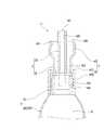
かかるペンは、図1に示す如く、液状のインクを貯留するインク貯留部6と、インクを含浸可能なペン先部7であって、棒状に成形されたペン先部7と、ペン先部7が軸心方向に移動可能に挿入された貫通孔80を有するホルダー部8と、ペン先部7とインク貯留部6との間に介設された弁機構9とを備える。 This pen is, as shown in FIG. 1, an
インク貯留部6は、一端と他端とを有する筒状の周壁部60と、周壁部60の一端を閉塞する尻部61とを備える。周壁部60及び尻部61は、インクを収容する内部空間S2を画定している。 The
ペン先部7は、図2に示す如く、棒状に形成され、軸線方向の一端部がインクの塗布対象にインクを塗布する塗布部70とされ、軸線方向の他端部がインクの供給位置となるインク供給部71とされている。ペン先部7は、フェルトや、不織布、綿、糸等の繊維材を成形にしたもので、全体的に吸液性を有する。 As shown in FIG. 2, the
ホルダー部8は、ペン先部7が挿入される貫通孔80を有するペン先保持部81を備える。また、本実施形態に係るホルダー部8は、弁機構9を保持する弁機構保持部82であって、ペン先保持部81と連続して形成された弁機構保持部82を備える。 The
ペン先保持部81は、筒状に形成されている。本実施形態において、ペン先保持部81は、段付き筒状に形成されている。すなわち、ペン先保持部81は、小径筒部810と、該小径筒部810よりも大径な大径筒部811であって、小径筒部810と連続する大径筒部811とを有する。これに伴い、小径筒部810の内孔80a、及び大径筒部811の内孔80bは、同心で連続し、ペン先部7を挿通させる貫通孔80を構成している。本実施形態において、小径筒部810の内孔80aは、ペン先部7の断面形状及び断面サイズに対応している。すなわち、小径筒部810の内孔80aを画定する内周面は、ペン先部7の外周面に接触可能に形成されている。これにより、ペン先部7は、外周面が小径筒部810の内周面にガイドされつつ軸心方向に移動可能で且つ抜き差し可能に貫通孔80に挿入される。 The pen
この種のペン5は、液状のインクをペン先部7に含浸させるため、一般的に、ペン先部7の周囲に配置される保湿部材83であって、ペン先部7の乾燥を防止するための保湿部材83を備える。保湿部材83は、吸液性を有し、インクを含浸可能に構成される。すなわち、保湿部材83は、フェルトや、不織布、綿、糸等の繊維材を成形にしたもの、或いは、海綿体で、全体的に吸液性を有する。ここでは、保湿部材83には、海綿体が採用されている。保湿部材83は、小径筒部810の内孔80aと同径又は略同径の内孔83aを有し、自身の内孔83aが小径筒部810の内孔80aと同心となるように、ホルダー部8の大径筒部811の内孔80bに嵌入されている。 This type of
これにより、ペン先部7は、塗布部70を小径筒部810から外方に突出させた状態で、小径筒部810の内孔80aと保湿部材83の内孔83aとに跨って配置される。 Thus, the
弁機構保持部82は、筒状に形成され、軸心方向に一端と他端とを有する。弁機構保持部82は、内孔82a内で弁機構9を保持可能に形成される。 The valve
本実施形態において、弁機構保持部82は、ペン先保持部81の大径筒部811よりも大径に設定され、一端が大径筒部811(ペン先保持部81)に接続されている。本実施形態において、弁機構保持部82の他端側は、インク貯留部6(周壁部60の他端部)に嵌着されている。これにより、ホルダー部8は、インク貯留部6の周壁部60の他端側を閉塞し、該インク貯留部6の内部空間S2を密閉している。 In the present embodiment, the valve
弁機構9は、貫通孔80とインク貯留部6(内部空間S2)とを繋ぐ連通路900を有する弁本体90であって、前記連通路900内に環状の弁座部901を有する弁本体90と、連通路900内にペン先部7の軸心方向で移動可能に配置された弁体91であって、ペン先部7側に付勢されることで弁座部901に当接して連通路900を閉じる弁体91とを備える。 The
弁本体90は、環状の弁座部901を有する第一部材92と、弁体91を案内する弁体案内部931を有する第二部材93であって、第一部材92と組み合わされる第二部材93とを備える。 The
第一部材92は、連通路900の一部を構成する内孔920aを有する筒状の本体部920であって、一端と反対側の他端とを有する本体部920と、本体部920の一端部から径方向外方に延出した鍔部921であって、外径が弁機構保持部82の内孔82aの内径と略同径に設定された鍔部921とを備える。 The
本体部920の内孔920aは、該本体部920の一端側にある大径孔部920bと、該大径孔部920bよりも小径な小径孔部920cであって、本体部920の他端側で大径孔部920bと繋がる小径孔部920cとによって構成される。 The
弁座部901は、小径孔部920cを画定する内周面と本体部920の他端面との境界に設けられる。具体的には、弁座部901は、環状のシール部材Sを備え、シール部材Sは、本体部920の他端面上にある小径孔部920cの開口縁部に配置されている。 The
第二部材93は、軸心方向に一端と他端とを有し、一端から他端までの長さが本体部920の一端から他端までのよりも長く設定された筒状本体部930であって、一端側が第一部材92の本体部920に外嵌可能な筒状本体部930と、弁体91(後述する案内部912)を挿入可能なガイド孔930aを有する環状の弁体案内部931であって、外周が筒状本体部930の他端に接続された弁体案内部931とを備える。 The
筒状本体部930の外径は、弁機構保持部82の内孔82aの内径と略同径に設定されている。 The outer diameter of the cylindrical
第二部材93の筒状本体部930は、内部に弁体91と該弁体91を付勢する付勢部材(ここではコイルバネ)94が配置された上で第一部材92の本体部920に外嵌される。この状態で、弁体案内部931は、付勢部材94であるコイルバネの一端を受けるバネ受部としても機能する。 The cylindrical
そして、鍔部921の外径、及び筒状本体部930の外径は、弁機構保持部82の内孔82aの内径と略同径に設定されているため、組み上げられた弁本体90は、弁機構保持部82の内孔82aに嵌入されることで、ホルダー部8の貫通孔80をペン先保持部81側と反対側とを液密に区画している。 Since the outer diameter of the
弁体91は、一端と他端とを有する弁部910であって、一端側が弁座部901のシール部材Sに対して当接可能な弁部910と、弁部910の一端から延出した被押圧部911であって、弁本体90における本体部920の内孔に挿通される被押圧部911と、弁部910の他端から延出した案内部912であって、弁本体90(第二部材93)のガイド孔930a内に配置される案内部912とを備える。 The
弁部910の一端側は、テーパー状に形成されており、該テーパー面が弁座部901(シール部材S)の全周に対して密接可能になっている。弁部910の他端は、弁体案内部931をバネ受けとして支持された付勢部材94に付勢される。すなわち、付勢部材94は、弁部910と弁案内部931との間に介設され、弁部910を介して弁体91全体をペン先部7側に付勢している。 One end side of the
被押圧部911は、棒状に形成され、当該被押圧部911の先端により、ホルダー部8の貫通孔80に挿通されたペン先部7のインク供給部71を支持するようになっている。被押圧部911の外径は、弁本体90における第一部材92の小径孔部920cよりも小径に設定されている。これにより、該小径孔部920cを画定する内周面と被押圧部911の外周面との間にインクを流通させるための隙間が形成可能になっている。なお、図示された被押圧部911は、先端で開放した孔部(採番しない)を有し、該孔部にもインクを保持させるようになっている。 The pressed
案内部912は、棒状に形成され、軸心方向に一端と他端とを有する。案内部912の一端は、弁部910の他端に接続されている。案内部912の他端部は、弁体案内部931のガイド孔930a内に配置される。より具体的には、案内部912の他端部は、一端部よりも大径に設定されており、外周面がガイド孔930aを画定する内周面に案内されるようになっている。なお、被押圧部911及び案内部912は、同心になるように配置されている。 The
本実施形態に係るインク充填具が前提とするペン5は、以上の通りであり、ペン先部7(塗布部70)を押圧することで、弁機構9の被押圧部911がペン先部7に押され、弁体91の弁部910が弁座部901(シール部材S)から離間するようになっている。すなわち、上記構成のペン5は、弁機構9を開弁させることで、インク貯留部6内のインクをペン先部7に対して供給するようになっている。 The
次に、本実施形態に係るインク充填具について説明する。 Next, the ink filler according to the present embodiment will be described.
インク充填具は、図3及び図4に示す如く、液状のインクを貯留可能な内部空間S1を有するインクタンク部20と、インクタンク部20の内部空間S1と連通する内孔300を有する筒状のノズル部30であって、前記貫通孔80に挿入可能なノズル部30とを備える。本実施形態に係るインク充填具1は、ノズル部30を包囲した環状のガイド部40であって、前記ペン5のホルダー部8に外嵌可能なガイド部40を更に備えている。 As shown in FIGS. 3 and 4, the ink filler has a tubular shape having an
より具体的に説明すると、図4に示す如く、本実施形態に係るインク充填具1は、インクタンク部20を含む貯留部材2と、ノズル部30を含む筒部材3と、筒部材3を貯留部材2に連結する連結部材4であって、ガイド部40を含む連結部材4とを備える。 If it demonstrates more concretely, as shown in FIG. 4, the
貯留部材2は、インクタンク部20と、インクタンク部20に接続された連結部21であって、筒部材3(ノズル部30)を連結するための連結部21とを備える。 The
インクタンク部20は、一端と他端とを有する筒状の胴部200と、胴部200の一端を閉塞する閉塞部201とを備える。インクタンク部20において、胴部200及び閉塞部201は、インクを収容する内部空間S1を画定している。連結部21は、筒状に形成されており、胴部200の他端に接続されている。本実施形態において、連結部21は、胴部200よりも小径に設定されている。連結部21の外周面上には、連結部材4を螺合させる雄ねじ210が形成されている。 The
図4及び図5に示す如く、筒部材3は、軸心方向に先端と基端とを有するノズル部30と、ノズル部30の基端部から径方向外方に延出した固定用鍔部31であって、貯留部材2に固定するための固定用鍔部31とを備える。 As shown in FIGS. 4 and 5, the
ノズル部30は、ペン5のホルダー部8の貫通孔80に挿入された状態で、ペン5の弁体91(被押圧部911)を押圧可能に構成される。また、ノズル部30は、自身の軸心と直交する方向で内孔300と外部とを連通させたインク流通部301を有する。 The
より具体的に説明する。ノズル部30の外径は、ペン5のホルダー部8の貫通孔80の孔径と略同径に設定されている。これにより、ノズル部30がペン5のホルダー部8の貫通孔80に挿入されるときに、ノズル部30の外周面がホルダー部8の貫通孔80の内周面に案内されるようになっている。 It will be described more specifically. The outer diameter of the
ノズル部30は、ペン5のホルダー部8の貫通孔80に挿入した状態で、弁体91の被押圧部911を押圧可能な長さに設定されている。すなわち、固定用鍔部31からノズル部30の先端までの長さは、弁部910が弁座部901(シール部材S)に接触した状態における被押圧部911の先端からペン先部7を外部に延出させるホルダー部8の先端までの距離よりも長く設定されている。 The
ノズル部30の内孔300は、先端及び基端で開口している。すなわち、ノズル部30の内孔300は、該ノズル部30の基端から先端までの全長に亘って形成されている。 The
インク流通部301は、ノズル部30の先端面に形成された凹部で構成されている。本実施形態において、インク流通部301は、ノズル部30の先端面の二箇所に設けられている。 The
固定用鍔部31の内径は、ノズル部30の内孔300の孔径と同径に設定され、固定用鍔部31の外径は、連結部21の外径と同径に設定されている。 The inner diameter of the fixing
連結部材4は、筒部材3の固定用鍔部31を貯留部材2の連結部21に固定する固定部41を備える。本実施形態において、連結部材4は、固定部41に加え、該固定部41に連設されたガイド部40を含む。 The connecting
固定部41は、連結部21に螺合可能で且つ連結部21の端面に重ね合わされ筒部材3の固定用鍔部31を連結部21側に押圧可能に構成される。具体的には、固定部41は、連結部21に外嵌状態で螺合される筒状の外嵌部410であって、軸心方向に一端及び他端を有する外嵌部410と、該外嵌部410に一端に接続された押圧部411であって、ノズル部30を挿通可能な挿通孔412を画定した押圧部411とを備える。 The fixing
外嵌部410の内周には、連結部21の外周に設けられた雄ねじ210に対して螺合可能な雌ねじ413が形成されている。 On the inner periphery of the outer
押圧部411は、外嵌部410の一端開口縁部の全周から径方向内方に延出している。これにより、押圧部411は、筒部材3のノズル部30を挿通可能な挿通孔412を画定している。また、押圧部411は、筒部材3の固定用鍔部31の少なくとも一部に重ね合わせることができるようになっている。 The
ガイド部40は、固定部41に連続して形成される。ガイド部40は、ペン5のホルダー部8に対して外嵌可能な筒状に形成される。具体的には、ガイド部40は、ペン5のホルダー部8を内挿可能な内孔400を有し、該内孔400を画定する内周面の少なくとも一部がペン5のホルダー部8の外周面に案内されるようになっている。本実施形態において、ガイド部40は、固定部41(外嵌部410)と同心で配置される。ガイド部40は、ノズル部30の先端がペン5の弁体91を押圧するまでは、ペン5(ホルダー部8)との干渉を起こさない長さに設定される。 The
本実施形態において、ガイド部40には、ペン5の一部と係合可能な係合部401が設けられている。より具体的には、ガイド部40には、ノズル部30がペン5の弁機構9を開弁した状態で、ペン5の一部と係合する係合部401が設けられる。係合部401は、凹部及び凸部の少なくとも何れか一方により構成され、ペン5の外周上にある既設の凹部又は凸部の少なくとも何れか他方に対して嵌合するようになっている。 In the present embodiment, the
本実施形態に係るインク充填具1は、ホルダー部8の外周に凹部84の形成されたペン5(図示しないキャップと係合させるための凹部84を有するペン5:図2参照)を対象としており、これに伴って、ガイド部40の内周面に係合部401としての凸部が設けられている。 The
上記構成の連結部材4は、筒部材3のノズル部30を押圧部411の画定した挿通孔412に挿通し、且つ押圧部411を筒部材3の固定用鍔部31に重ね合わせた状態で、外嵌部410を連結部21に螺合することで、押圧部411が筒部材3の固定用鍔部31を連結部21の端面とともに挟み込むようになっている。すなわち、外嵌部410が連結部21に螺合されることで、押圧部411が連結部21側に引き寄せられて固定用鍔部31を押圧するようになっている。これにより、固定用鍔部31と連結部21との間が密接(圧接)することになり、筒部材3と貯留部材2との間からの液漏れ(インク漏れ)が防止される。 The connecting
このように、連結部材4によって筒部材3が固定されたとき、筒部材3は押圧部411の挿通孔412を画定する内周面によって位置決めされ、ノズル部30がガイド部40と同心をなす。 As described above, when the
本実施形態に係るインク充填具1は、以上の通りであり、図6及び図7に示す如く、インクの充填の対象となるペン5のペン先部7をホルダー部8(貫通孔80)から抜き取った上で、ノズル部30がペン5のホルダー部8における貫通孔80に挿入される。このとき、ノズル部30が貫通孔80に真っ直ぐ浸入するように、ガイド部40は、ペン5のホルダー部8に案内される。 The
そして、ノズル部30がペン5の弁機構9(弁体91)に到達し、インク充填具1全体がペン5側に押圧されると、図7に示す如く、ノズル部30が弁体91を押圧し、弁機構9が開弁する。すなわち、弁部910が弁座部901から離間し、該弁部910を境にした連通路900の一方側と他方側とが連通する。 Then, when the
本実施形態においては、弁機構9が開弁すると、ガイド部40の係合部401がペン5の一部と係合する。すなわち、ガイド部40の係合部401としての凸部がペン5のホルダー部8の凹部84に嵌合(係合)し、ノズル部30が弁体91を押圧した状態(弁機構9を開弁させた状態)で維持する。 In the present embodiment, when the
これにより、インクタンク部20の内部空間S1は、ホルダー部8の貫通孔80内にあるノズル部30の内孔300、インク流通部301、及び開放状態にある連通路900を介してインク貯留部6の内部空間S2と連通した状態となる。 Thereby, the internal space S1 of the
従って、インク充填具1は、インクタンク部20内のインクを、ノズル部30の内孔300、インク流通部301、及び連通路900を経由させてインク貯留部6に流入させることができる。なお、本実施形態に係るインク充填具1は、インクタンク部20の内部空間S1とノズル部30の内孔300とが直接連通しているため、インクタンク部20内のインクを自由落下によりペン5に供給する必要がある。従って、上述の如く、インクタンク部20内のインクをペン5に供給するに当り、本実施形態に係るインク充填具1はペン5より上方に位置するように配置される(図6参照)。 Therefore, the
そして、ペン5のインク貯留部6にインクが必要量供給されると、ノズル部30をホルダー部8(貫通孔80)から抜き取るようにインク充填具1全体を移動させる。そうすると、ノズル部30による弁体91の押圧が解除される。その結果、弁体91が弁座部901に当接し、弁機構9(弁本体90)内の連通路900が閉塞されるため、インク貯留部6内のインクの漏洩が防止される。そして、ホルダー部8(貫通孔80)にペン先部7が挿入されることで、インク切れであったペン5が再使用可能な状態となる。 Then, when the necessary amount of ink is supplied to the
以上のように、インク充填具1は、液状のインクを貯留するインク貯留部6と、インクを含浸可能なペン先部7であって、棒状に成形されたペン先部7と、ペン先部7が軸心方向に移動可能に挿入された貫通孔80を有するホルダー部8と、ペン先部7とインク貯留部6との間に介設された弁機構9であって、ペン先部7によって押圧されることで開弁し、インク貯留部6とペン先部7とを繋ぐ連通路900を開放させる弁機構9とを備えたペン5に対してインクを補充するためのインク充填具1であって、液状のインクを貯留可能な内部空間S1を有するインクタンク部20と、インクタンク部20の内部空間S1と連通する内孔300を有する筒状のノズル部30であって、前記貫通孔80に挿入可能なノズル部30とを備え、ノズル部30は、貫通孔80に挿入された状態で弁機構9を押圧操作可能に構成されるとともに、自身の軸心と直交する方向で内孔300と外部とを連通させたインク流通部301を有する。 As described above, the
従って、上記構成のインク充填具1によれば、インクの充填の対象となるペン5のペン先部7をホルダー部8(貫通孔80)から抜き取った上で、ノズル部30がペン5のホルダー部8における貫通孔80に挿入されると、ノズル部30がペン5の弁機構9に到達する。 Therefore, according to the
そして、インク充填具1全体がペン5側に押圧されると、ノズル部30が弁機構9を押圧操作し、弁機構9を開弁させる。そうすると、インクタンク部20の内部空間S1は、ホルダー部8の貫通孔80内にあるノズル部30の内孔300、インク流通部301、及び開放状態にある連通路900を介してインク貯留部6の内部空間S2と連通した状態となる。 Then, when the
より具体的に説明すると、ノズル部30の内孔300がインクタンク部20から真っ直ぐ延びた上でノズル部30の先端部で閉塞した状態で形成されたり、ノズル部30の内孔がインクタンク部20から真っ直ぐ延びた上でノズル部30の先端で開放して形成され、弁機構9に対する押圧操作によって閉ざされるように形成されたりすると、インクの流量が遮断されてしまう。 More specifically, the
しかし、上記構成のインク充填具1のノズル部30は、自身の軸心と直交する方向で内孔300と外部とを連通させたインク流通部301を有するため、ノズル部30の先端と異なる位置にあるインク流通部301を介してノズル部30の内孔300と開放状態の連通路900とが連通し、結果的にインクタンク部20とインク貯留部6とが連通する。 However, since the
これにより、インク充填具1は、インクタンク部20内のインクを、ノズル部30の内孔300、インク流通部301、及び連通路900を経由させてインク貯留部6に流入させることができる。 Thus, the
そして、ペン5のインク貯留部6にインクが必要量供給されると、ノズル部30をホルダー部8(貫通孔80)から抜き取るようにインク充填具1全体を移動させる。そうすると、ノズル部30による弁機構9に対する押圧操作が解除される。その結果、弁機構9内の連通路900が閉塞されるため、インク貯留部6のインクの漏洩が防止される。そして、ホルダー部8(貫通孔80)にペン先部7が挿入されることで、インク切れであったペン5が再使用可能な状態となる。 Then, when the necessary amount of ink is supplied to the
また、本実施形態に係るインク充填具1は、ノズル部30を包囲した環状のガイド部40であって、前記ペン5のホルダー部8に外嵌可能なガイド部40を更に備えているため、ペン5のホルダー部8の貫通孔80にノズル部30を挿入するに当り、ガイド部40がホルダー部8の外周に案内される。従って、ノズル部30をホルダー部8の貫通孔80に対して適正且つ確実に挿入することができる。 Further, the
特に、ノズル部30の内孔300は、先端で開口し、前記インク流通部301は、ノズル部30の先端面に形成された凹部で構成されているため、ノズル部30が弁体91を押圧したときに、ノズル部30の先端で開口した内孔は弁体91によって閉じられるのに併せて、インク流通部(凹部)301の開放部分が弁体91によって閉じられる。従って、インク流通部301が孔状になり、インクを内孔から外方に流出させることができる。 In particular, since the
なお、本発明は、上記実施形態に限定されるものではなく、本発明の要旨を逸脱しない範囲で適宜変更可能である。 The present invention is not limited to the above embodiment, and can be appropriately modified without departing from the scope of the present invention.
上記実施形態において、インク充填具1の対象となるペン5として、インク貯留部6とホルダー部8とが別部材として構成されたものを一例に挙げたが、これに限定されない。例えば、インク貯留部6とホルダー部8とが一体的に形成されたものであってもよい。すなわち、本実地形態に係るインク充填具1の対象とするペン5のホルダー部8は、ペン5におけるペン先部7を露出させる先端部を意味するものであり、他の構成との関係で一体であってもよいし、別体であってもよい。 In the above-described embodiment, as the
また、弁機構9等も上記実施形態で説明したものに限定されるものではなく、上記実施形態で説明したものとは異なる弁機構9を備えたペン5であってもよい。すなわち、インク充填具1の対象となるペン5は、ペン先部7とインク貯留部6との間に介設された弁機構9であって、ペン先部7によって押圧されることで開弁し、インク貯留部6とペン先部7とを繋ぐ連通路900を開放させる弁機構9とを備えたものであればよい。 Further, the
ようは、インク充填具1の対象となるペン5は、液状のインクを貯留するインク貯留部6と、インクを含浸可能なペン先部7であって、棒状に成形されたペン先部7と、ペン先部7が軸心方向に移動可能に挿入された貫通孔80を有するホルダー部8と、ペン先部7とインク貯留部6との間に介設された弁機構9とを備えたものあり、弁機構9は、貫通孔80とインク貯留部6とを繋ぐ連通路900を有する弁本体90であって、前記連通路900内に環状の弁座部901を有する弁本体90と、連通路900内にペン先部7の軸心方向で移動可能に配置された弁体91であって、ペン先部7側に付勢されることで弁座部901に当接して連通路900を閉じる弁体91とを備え、ペン先部7が軸心方向に押圧されることで該ペン先部7が弁体91を押圧して開弁するように構成されたものであればよい。 The
上記実施形態において、ペン5のホルダー部8に外嵌可能なガイド部40が設けられ、ノズル部30をペン5の貫通孔80に挿入するに当たってガイド部40がペン5のホルダー部8に案内されるように構成されたが、これに限定されない。例えば、ガイド部40が設けられることなく、単にノズル部30がペン5のホルダー部8の貫通孔80に挿入されるものであってもよい。すなわち、インク充填具1は、少なくともインクタンク部20及びノズル部30を備えたものであればよい。 In the above embodiment, the
上記実施形態において、ノズル部30の先端に設けられた凹部によってインク流通部301が形成されたが、これに限定されない。例えば、図8に示す如く、インク流通部301は、ノズル部30の途中位置に設けられたものであってもよい。すなわち、インク流通部301は、ノズル部30の内孔300と外部とを連通させる孔であってもよい。但し、インク流通部301は、ノズル部30がペン5のホルダー部8の貫通孔80に挿入された状態で、ペン5内で開放し得る位置に配置されることは言うまでもない。 In the above embodiment, the
上記実施形態において、インク充填具1は、インクタンク部20、ノズル部30、ガイド部40がそれぞれ別部材の一部として構成され、これらの部材を組み付けることで形成されたが、これに限定されるものではなく、インクタンク部20及びノズル部30が一体的に成型されたものや、インクタンク部20、ノズル部30、及びガイド部40が一体的に成型されたものであってもよい。 In the above embodiment, the
上記実施形態において、ガイド部40がペン5の一部に係合する係合部401を備えたが、これに限定されない。例えば、ガイド部40が設けられる場合、ガイド部40は単にペン5のホルダー部8に案内される機能を有するものであってもよい。但し、ペン5の弁機構9を開弁状態で維持させるには、付勢部材94の付勢力に対抗する押圧力を作用させる必要があるため、上記実施形態のようにペン5とインク充填具1との相対的な位置を固定できる係合部401を設けることが好ましい。 Although the
上記実施形態において、ホルダー部8にある既設の凹部に係合部401としての凸部が嵌合するようにしたが、これに限定されない。例えば、ガイド部40が設けられるとともに、該ガイド部40に係合部401が設けられる場合、インク貯留部6とホルダー部8との境界に形成される凹部に対して嵌合可能な凸部をガイド部40に設けてもよい。また、上記実施形態において、ペン5にある既設の凹部に係合可能(嵌合可能)な係合部401としての凸部を設けたが、これに限定されない。例えば、ペン5にある既設の凸部に係合可能な係合部401としてガイド部40に凹部を設けるようにしてもよい。また、ペン5にある既設の凸部及び凹部に係合可能な係合部401としてガイド部40に凹部及び凸部を設けるようにしてもよい。 In the said embodiment, although the convex part as the
1…インク充填具、2…貯留部材、3…筒部材、4…連結部材、5…ペン、6…インク貯留部、7…ペン先部、8…ホルダー部、9…弁機構、20…インクタンク部、21…連結部、30…ノズル部、31…固定用鍔部、40…ガイド部、41…固定部、60…周壁部、61…尻部、70…塗布部、71…インク供給部、80…貫通孔、80a…内孔、80b…内孔、81…ペン先保持部、82…弁機構保持部、82a…内孔、83…保湿部材、83a…内孔、84…凹部、90…弁本体、91…弁体、92…第一部材、93…第二部材、94…付勢部材、200…胴部、201…閉塞部、300…内孔、301…インク流通部、400…内孔、401…係合部、410…外嵌部、411…押圧部、412…挿通孔、810…小径筒部、811…大径筒部、900…連通路、901…弁座部、910…弁部、911…被押圧部、912…案内部、920…本体部、920a…内孔、920b…大径孔部、920c…小径孔部、921…鍔部、930…筒状本体部、930a…ガイド孔、931…弁体案内部、S…シール部材、S1…内部空間、S2…内部空間 DESCRIPTION OF
Claims (2)
Translated fromJapaneseThe inner hole of the nozzle portion is open at the tip, the ink circulation unit, the ink filling device ofclaim 1, which consists of a recess formed in the end surface of the nozzle portion.
Priority Applications (6)
| Application Number | Priority Date | Filing Date | Title |
|---|---|---|---|
| JP2014212004AJP6514480B2 (en) | 2014-10-16 | 2014-10-16 | Ink filler |
| CN201580056155.XACN107074005A (en) | 2014-10-16 | 2015-10-14 | Ink packing tool |
| KR1020177010751AKR20170069231A (en) | 2014-10-16 | 2015-10-14 | Ink filling device |
| PCT/JP2015/079097WO2016060187A1 (en) | 2014-10-16 | 2015-10-14 | Ink filling device |
| EP15850953.9AEP3208103A4 (en) | 2014-10-16 | 2015-10-14 | Ink filling device |
| US15/518,600US10081216B2 (en) | 2014-10-16 | 2015-10-14 | Ink filling tool |
Applications Claiming Priority (1)
| Application Number | Priority Date | Filing Date | Title |
|---|---|---|---|
| JP2014212004AJP6514480B2 (en) | 2014-10-16 | 2014-10-16 | Ink filler |
Publications (2)
| Publication Number | Publication Date |
|---|---|
| JP2016078326A JP2016078326A (en) | 2016-05-16 |
| JP6514480B2true JP6514480B2 (en) | 2019-05-15 |
Family
ID=55746729
Family Applications (1)
| Application Number | Title | Priority Date | Filing Date |
|---|---|---|---|
| JP2014212004AActiveJP6514480B2 (en) | 2014-10-16 | 2014-10-16 | Ink filler |
Country Status (6)
| Country | Link |
|---|---|
| US (1) | US10081216B2 (en) |
| EP (1) | EP3208103A4 (en) |
| JP (1) | JP6514480B2 (en) |
| KR (1) | KR20170069231A (en) |
| CN (1) | CN107074005A (en) |
| WO (1) | WO2016060187A1 (en) |
Families Citing this family (3)
| Publication number | Priority date | Publication date | Assignee | Title |
|---|---|---|---|---|
| JP6514480B2 (en)* | 2014-10-16 | 2019-05-15 | 株式会社呉竹 | Ink filler |
| US10730338B2 (en) | 2017-04-26 | 2020-08-04 | Hayden R Murphy | Fluid applicator refill system |
| WO2019211454A1 (en)* | 2018-05-03 | 2019-11-07 | Firas Kiwan | A refillable whiteboard pen, an apparatus for refilling it, and a method of refilling it in the apparatus |
Family Cites Families (39)
| Publication number | Priority date | Publication date | Assignee | Title |
|---|---|---|---|---|
| US2130926A (en) | 1937-07-15 | 1938-09-20 | William G Nichol | Fountain pen |
| DE9214185U1 (en)* | 1992-10-21 | 1993-02-25 | Hermann Böhler GmbH, 6830 Schwetzingen | Reserve bottle for refilling ink in piston fountain pens or writing instruments equipped with an ink tank and ink feed system |
| JP2594306Y2 (en)* | 1992-12-25 | 1999-04-26 | パイロットインキ株式会社 | Direct liquid writing instrument |
| DE9304466U1 (en) | 1993-03-24 | 1993-05-13 | Rathenberg, Jürgen, Dr. med., 3353 Bad Gandersheim | Piston fountain pen |
| US5518331A (en)* | 1993-04-15 | 1996-05-21 | Storelic Ag | Refillable ink pen |
| NL9301020A (en)* | 1993-06-11 | 1995-01-02 | Raycap Bv | Method of filling a cartridge with a liquid and system for carrying it out. |
| DE59409687D1 (en)* | 1993-11-30 | 2001-04-19 | Pelikan Ag | Writing instrument, in particular fountain pens |
| CA2147916C (en)* | 1994-04-29 | 2005-03-22 | Masashi Ando | Ballpoint pen tip, manufacturing method therefor, and ballpoint pen using the same |
| JPH0872469A (en) | 1994-09-07 | 1996-03-19 | Mitsubishi Pencil Co Ltd | Writing implement with ink valve |
| US5678942A (en)* | 1995-02-28 | 1997-10-21 | Mitsubishi Pencil Kabushiki Kaisha | Ball-point pen |
| US5906446A (en)* | 1996-10-22 | 1999-05-25 | Bic Corporation | Fillerless writing instrument |
| KR100720698B1 (en)* | 2000-03-22 | 2007-05-21 | 미쓰비시 펜슬 가부시키가이샤 | Writing utensils |
| CN1222426C (en) | 2000-05-15 | 2005-10-12 | 阿什拉夫·马赫福兹·阿巴斯 | Fluid Applicator |
| JP2002036779A (en)* | 2000-07-31 | 2002-02-06 | Pentel Corp | Ink refill container |
| JP3507036B2 (en)* | 2001-01-18 | 2004-03-15 | 株式会社呉竹 | Writing implement |
| US6702498B2 (en)* | 2001-05-29 | 2004-03-09 | Mitsubishi Pencil Kabushiki Kaisha | Writing implement |
| JP3927034B2 (en)* | 2002-01-07 | 2007-06-06 | 株式会社呉竹 | Brush cover member and brush |
| TWI260280B (en)* | 2002-05-31 | 2006-08-21 | Pentel Kk | Applicator |
| JP4298968B2 (en)* | 2002-06-19 | 2009-07-22 | 株式会社呉竹 | Writing instrument |
| US7044675B2 (en)* | 2002-12-10 | 2006-05-16 | Bic Corporation | Leak resistant writing instrument |
| WO2005017056A1 (en)* | 2003-08-19 | 2005-02-24 | Mitsubishi Pencil Co., Ltd. | Fluid application liquid and fluid application tool |
| KR100946428B1 (en)* | 2006-03-09 | 2010-03-10 | 파일롯트 잉크 가부시키가이샤 | Direct Writing Instruments |
| DE202006017655U1 (en)* | 2006-11-20 | 2008-04-03 | Schwan-Stabilo Cosmetics Gmbh & Co. Kg | applicator |
| JP2008155624A (en)* | 2006-11-29 | 2008-07-10 | Pilot Ink Co Ltd | Frictional element and writing utensil using it, and writing utensil set |
| US7758270B2 (en)* | 2008-04-08 | 2010-07-20 | Cartier Creation Studio S.A. | Ink refill tool for a writing instrument |
| US8408831B2 (en)* | 2009-07-31 | 2013-04-02 | Peter A. Paradise | Writing instrument casing and methods of use |
| US20110103875A1 (en)* | 2009-11-03 | 2011-05-05 | Shih-Yuan Huang | Retractable push button pen |
| US8092108B2 (en)* | 2009-12-30 | 2012-01-10 | Harry Bainbridge | Porous tip liquid applicator having draw fill mechanism |
| JP5581075B2 (en)* | 2010-02-24 | 2014-08-27 | 三菱鉛筆株式会社 | Writing instrument |
| JP5687529B2 (en)* | 2010-03-26 | 2015-03-18 | 株式会社サクラクレパス | Applicator |
| CA2795025A1 (en) | 2010-03-31 | 2011-10-06 | Beauty Union Global Ltd. | Refill system and method |
| JP2012135916A (en)* | 2010-12-25 | 2012-07-19 | Mitsubishi Pencil Co Ltd | Ink refill device and writing implement set with ink refill device |
| JP5794732B2 (en)* | 2011-08-22 | 2015-10-14 | 三菱鉛筆株式会社 | Replenisher and writing instrument set with replenisher |
| US20130233242A1 (en)* | 2012-03-06 | 2013-09-12 | Juergen Feuerstein | Application tool |
| CN104837643B (en)* | 2012-12-06 | 2017-07-11 | 欧洲品牌有限责任公司 | Refilling connector release sub-assembly and the writing implement including it |
| JP6367561B2 (en)* | 2014-01-20 | 2018-08-01 | 株式会社呉竹 | Writing instrument refill and writing instrument |
| CN204160938U (en)* | 2014-01-22 | 2015-02-18 | 汇美环球有限公司 | Marking device |
| GB201413027D0 (en)* | 2014-02-28 | 2014-09-03 | Beyond Twenty Ltd | Beyond 4 |
| JP6514480B2 (en)* | 2014-10-16 | 2019-05-15 | 株式会社呉竹 | Ink filler |
- 2014
- 2014-10-16JPJP2014212004Apatent/JP6514480B2/enactiveActive
- 2015
- 2015-10-14CNCN201580056155.XApatent/CN107074005A/enactivePending
- 2015-10-14EPEP15850953.9Apatent/EP3208103A4/enactivePending
- 2015-10-14KRKR1020177010751Apatent/KR20170069231A/ennot_activeCeased
- 2015-10-14USUS15/518,600patent/US10081216B2/enactiveActive
- 2015-10-14WOPCT/JP2015/079097patent/WO2016060187A1/enactiveApplication Filing
Also Published As
| Publication number | Publication date |
|---|---|
| US20170246901A1 (en) | 2017-08-31 |
| KR20170069231A (en) | 2017-06-20 |
| EP3208103A1 (en) | 2017-08-23 |
| JP2016078326A (en) | 2016-05-16 |
| US10081216B2 (en) | 2018-09-25 |
| CN107074005A (en) | 2017-08-18 |
| WO2016060187A1 (en) | 2016-04-21 |
| EP3208103A4 (en) | 2018-05-09 |
Similar Documents
| Publication | Publication Date | Title |
|---|---|---|
| JP6736144B2 (en) | Applicator | |
| JP6367561B2 (en) | Writing instrument refill and writing instrument | |
| JP6514480B2 (en) | Ink filler | |
| JP6145272B2 (en) | Applicator | |
| US9862225B2 (en) | Liquid applying tool | |
| TW201446551A (en) | Writng implement and ink cartridge | |
| KR100518193B1 (en) | The tool for spreading liquid cosmetic material | |
| JP2013102910A (en) | Liquid dispenser | |
| JP5866747B2 (en) | Applicator | |
| JP2016078324A (en) | Pen and refill for pen | |
| WO2014041901A1 (en) | Writing instrument | |
| US3145412A (en) | Writing instrument | |
| JP2019135082A (en) | Direct liquid type brush pen | |
| US9950555B2 (en) | Ink reservoir member for writing instrument, and valve type writing instrument using the same | |
| US8905666B2 (en) | Liquid applicator | |
| JP3926008B2 (en) | Applicator | |
| JP5328323B2 (en) | Applicator | |
| JP2021003842A (en) | Applicator | |
| JP6748040B2 (en) | Valve type liquid material exuding tool | |
| JP2014128891A (en) | Applicator | |
| JP3722242B2 (en) | Water-based ballpoint pen | |
| KR100655426B1 (en) | Writing instruments that can be used for a long time | |
| US610818A (en) | Fountain-pen | |
| JP2006123433A (en) | Liquid type writing implement | |
| JP2008087280A (en) | Liquid type writing utensil |
Legal Events
| Date | Code | Title | Description |
|---|---|---|---|
| A621 | Written request for application examination | Free format text:JAPANESE INTERMEDIATE CODE: A621 Effective date:20170920 | |
| A131 | Notification of reasons for refusal | Free format text:JAPANESE INTERMEDIATE CODE: A131 Effective date:20180914 | |
| A521 | Request for written amendment filed | Free format text:JAPANESE INTERMEDIATE CODE: A523 Effective date:20181029 | |
| TRDD | Decision of grant or rejection written | ||
| A01 | Written decision to grant a patent or to grant a registration (utility model) | Free format text:JAPANESE INTERMEDIATE CODE: A01 Effective date:20190328 | |
| A61 | First payment of annual fees (during grant procedure) | Free format text:JAPANESE INTERMEDIATE CODE: A61 Effective date:20190412 | |
| R150 | Certificate of patent or registration of utility model | Ref document number:6514480 Country of ref document:JP Free format text:JAPANESE INTERMEDIATE CODE: R150 | |
| R250 | Receipt of annual fees | Free format text:JAPANESE INTERMEDIATE CODE: R250 | |
| R250 | Receipt of annual fees | Free format text:JAPANESE INTERMEDIATE CODE: R250 | |
| R250 | Receipt of annual fees | Free format text:JAPANESE INTERMEDIATE CODE: R250 | |
| R250 | Receipt of annual fees | Free format text:JAPANESE INTERMEDIATE CODE: R250 |