JP6514100B2 - Communication apparatus, communication system and network management method - Google Patents
Communication apparatus, communication system and network management methodDownload PDFInfo
- Publication number
- JP6514100B2 JP6514100B2JP2015256703AJP2015256703AJP6514100B2JP 6514100 B2JP6514100 B2JP 6514100B2JP 2015256703 AJP2015256703 AJP 2015256703AJP 2015256703 AJP2015256703 AJP 2015256703AJP 6514100 B2JP6514100 B2JP 6514100B2
- Authority
- JP
- Japan
- Prior art keywords
- information
- communication
- management
- unit
- transmission
- Prior art date
- Legal status (The legal status is an assumption and is not a legal conclusion. Google has not performed a legal analysis and makes no representation as to the accuracy of the status listed.)
- Active
Links
Images


Classifications
- H—ELECTRICITY
- H04—ELECTRIC COMMUNICATION TECHNIQUE
- H04M—TELEPHONIC COMMUNICATION
- H04M7/00—Arrangements for interconnection between switching centres
- H04M7/12—Arrangements for interconnection between switching centres for working between exchanges having different types of switching equipment, e.g. power-driven and step by step or decimal and non-decimal
- H04M7/1205—Arrangements for interconnection between switching centres for working between exchanges having different types of switching equipment, e.g. power-driven and step by step or decimal and non-decimal where the types of switching equipement comprises PSTN/ISDN equipment and switching equipment of networks other than PSTN/ISDN, e.g. Internet Protocol networks
- H04M7/126—Interworking of session control protocols
- H—ELECTRICITY
- H04—ELECTRIC COMMUNICATION TECHNIQUE
- H04L—TRANSMISSION OF DIGITAL INFORMATION, e.g. TELEGRAPHIC COMMUNICATION
- H04L69/00—Network arrangements, protocols or services independent of the application payload and not provided for in the other groups of this subclass
- H04L69/18—Multiprotocol handlers, e.g. single devices capable of handling multiple protocols
- G—PHYSICS
- G06—COMPUTING OR CALCULATING; COUNTING
- G06F—ELECTRIC DIGITAL DATA PROCESSING
- G06F13/00—Interconnection of, or transfer of information or other signals between, memories, input/output devices or central processing units
- H—ELECTRICITY
- H04—ELECTRIC COMMUNICATION TECHNIQUE
- H04L—TRANSMISSION OF DIGITAL INFORMATION, e.g. TELEGRAPHIC COMMUNICATION
- H04L12/00—Data switching networks
- H04L12/28—Data switching networks characterised by path configuration, e.g. LAN [Local Area Networks] or WAN [Wide Area Networks]
- H04L12/46—Interconnection of networks
- H—ELECTRICITY
- H04—ELECTRIC COMMUNICATION TECHNIQUE
- H04L—TRANSMISSION OF DIGITAL INFORMATION, e.g. TELEGRAPHIC COMMUNICATION
- H04L12/00—Data switching networks
- H04L12/66—Arrangements for connecting between networks having differing types of switching systems, e.g. gateways
- H—ELECTRICITY
- H04—ELECTRIC COMMUNICATION TECHNIQUE
- H04L—TRANSMISSION OF DIGITAL INFORMATION, e.g. TELEGRAPHIC COMMUNICATION
- H04L41/00—Arrangements for maintenance, administration or management of data switching networks, e.g. of packet switching networks
- H04L41/02—Standardisation; Integration
- H04L41/022—Multivendor or multi-standard integration
- H—ELECTRICITY
- H04—ELECTRIC COMMUNICATION TECHNIQUE
- H04L—TRANSMISSION OF DIGITAL INFORMATION, e.g. TELEGRAPHIC COMMUNICATION
- H04L41/00—Arrangements for maintenance, administration or management of data switching networks, e.g. of packet switching networks
- H04L41/02—Standardisation; Integration
- H04L41/0226—Mapping or translating multiple network management protocols
- H—ELECTRICITY
- H04—ELECTRIC COMMUNICATION TECHNIQUE
- H04L—TRANSMISSION OF DIGITAL INFORMATION, e.g. TELEGRAPHIC COMMUNICATION
- H04L41/00—Arrangements for maintenance, administration or management of data switching networks, e.g. of packet switching networks
- H04L41/08—Configuration management of networks or network elements
- H04L41/085—Retrieval of network configuration; Tracking network configuration history
- H04L41/0853—Retrieval of network configuration; Tracking network configuration history by actively collecting configuration information or by backing up configuration information
- H—ELECTRICITY
- H04—ELECTRIC COMMUNICATION TECHNIQUE
- H04L—TRANSMISSION OF DIGITAL INFORMATION, e.g. TELEGRAPHIC COMMUNICATION
- H04L41/00—Arrangements for maintenance, administration or management of data switching networks, e.g. of packet switching networks
- H04L41/22—Arrangements for maintenance, administration or management of data switching networks, e.g. of packet switching networks comprising specially adapted graphical user interfaces [GUI]
- H—ELECTRICITY
- H04—ELECTRIC COMMUNICATION TECHNIQUE
- H04L—TRANSMISSION OF DIGITAL INFORMATION, e.g. TELEGRAPHIC COMMUNICATION
- H04L47/00—Traffic control in data switching networks
- H04L47/10—Flow control; Congestion control
- H04L47/26—Flow control; Congestion control using explicit feedback to the source, e.g. choke packets
- H04L47/263—Rate modification at the source after receiving feedback
- H—ELECTRICITY
- H04—ELECTRIC COMMUNICATION TECHNIQUE
- H04M—TELEPHONIC COMMUNICATION
- H04M3/00—Automatic or semi-automatic exchanges
- H—ELECTRICITY
- H04—ELECTRIC COMMUNICATION TECHNIQUE
- H04M—TELEPHONIC COMMUNICATION
- H04M7/00—Arrangements for interconnection between switching centres
- H04M7/12—Arrangements for interconnection between switching centres for working between exchanges having different types of switching equipment, e.g. power-driven and step by step or decimal and non-decimal
- H04M7/1205—Arrangements for interconnection between switching centres for working between exchanges having different types of switching equipment, e.g. power-driven and step by step or decimal and non-decimal where the types of switching equipement comprises PSTN/ISDN equipment and switching equipment of networks other than PSTN/ISDN, e.g. Internet Protocol networks
- H04M7/1285—Details of finding and selecting a gateway for a particular call
- H—ELECTRICITY
- H04—ELECTRIC COMMUNICATION TECHNIQUE
- H04L—TRANSMISSION OF DIGITAL INFORMATION, e.g. TELEGRAPHIC COMMUNICATION
- H04L12/00—Data switching networks
- H04L12/28—Data switching networks characterised by path configuration, e.g. LAN [Local Area Networks] or WAN [Wide Area Networks]
- H04L12/46—Interconnection of networks
- H04L12/4604—LAN interconnection over a backbone network, e.g. Internet, Frame Relay
- H—ELECTRICITY
- H04—ELECTRIC COMMUNICATION TECHNIQUE
- H04L—TRANSMISSION OF DIGITAL INFORMATION, e.g. TELEGRAPHIC COMMUNICATION
- H04L41/00—Arrangements for maintenance, administration or management of data switching networks, e.g. of packet switching networks
- H04L41/12—Discovery or management of network topologies
- H—ELECTRICITY
- H04—ELECTRIC COMMUNICATION TECHNIQUE
- H04L—TRANSMISSION OF DIGITAL INFORMATION, e.g. TELEGRAPHIC COMMUNICATION
- H04L69/00—Network arrangements, protocols or services independent of the application payload and not provided for in the other groups of this subclass
- H04L69/08—Protocols for interworking; Protocol conversion
Landscapes
- Engineering & Computer Science (AREA)
- Signal Processing (AREA)
- Computer Networks & Wireless Communication (AREA)
- Human Computer Interaction (AREA)
- Theoretical Computer Science (AREA)
- Computer Security & Cryptography (AREA)
- General Engineering & Computer Science (AREA)
- General Physics & Mathematics (AREA)
- Physics & Mathematics (AREA)
- Data Exchanges In Wide-Area Networks (AREA)
- Computer And Data Communications (AREA)
- Small-Scale Networks (AREA)
- Telephonic Communication Services (AREA)
Description
Translated fromJapanese本発明の実施形態は、通信装置、通信システム及びネットワーク管理方法に関する。 Embodiments of the present invention relate to a communication apparatus, a communication system, and a network management method.
近年、多様な通信機器をネットワークに接続するニーズが高まっている。例えば、世の中のあらゆるモノをインターネットに接続することによって、新たなソリューションを生み出そうとするIoT(Internet of Things)技術が注目を浴びている。例えば、個々のモノには、センサや通信装置等の機器が備えられ、個々のモノについて取得されるセンサの計測情報に基づいてモノの動きや分布等を取得することができる。また、オフィスビルやホテル、工場等の商業施設などに様々なセンサを設置し、センサによって取得される種々の情報を省エネやマーケティングに活用することが検討されている。 In recent years, the need to connect various communication devices to networks has increased. For example, the Internet of Things (IoT) technology that draws on new solutions by connecting everything in the world to the Internet is drawing attention. For example, each thing is equipped with an apparatus such as a sensor or a communication device, and the movement, distribution, and the like of the thing can be obtained based on measurement information of the sensor obtained for each thing. In addition, various sensors are installed in office buildings, hotels, commercial facilities such as factories, etc., and it is considered to utilize various information acquired by the sensors for energy saving and marketing.
一方で、近年では、センサの通信方式が多様化している。センサの通信プロトコルやバックボーンのネットワーク構成は、メーカや用途に応じて異なる場合が多く、共通化が困難である。そのため、上記のニーズに答える通信システムを、特定の通信方式に統一して構築することは困難である。そこで、異種プロトコルの混在を可能とする通信ネットワークの形態が模索されている。 On the other hand, in recent years, communication systems of sensors have diversified. The communication protocol of the sensor and the network configuration of the backbone are often different depending on the manufacturer and the application, and it is difficult to share them. Therefore, it is difficult to unify and construct the communication system which answers the above-mentioned needs to a specific communication system. Therefore, a form of communication network that enables the mixture of different protocols is being sought.
しかしながら、異種プロトコルが混在することでネットワークは複雑化し、ネットワーク管理者の管理負荷が高まることが予想される。また、ネットワークに接続された機器を管理するために必要な情報(以下、「ネットワーク管理情報」という。)の量も増加し、ネットワーク管理情報のトラフィックがネットワークを圧迫するという問題の発生も予想される。そのため、通信プロトコルが混在する通信システムにおいて、ネットワークの管理にかかる負荷を低減する手法の確立が望まれている。 However, it is expected that the network will be complicated by the mixture of different protocols, and the management load on the network administrator will increase. In addition, the amount of information required to manage the devices connected to the network (hereinafter referred to as "network management information") is also increased, and the occurrence of a problem that the traffic of the network management information may overwhelm the network is also expected. Ru. Therefore, in a communication system in which communication protocols coexist, it is desired to establish a method for reducing the load on network management.
本発明が解決しようとする課題は、異なる通信プロトコルが混在する通信システムにおいて、ネットワークの管理にかかる負荷を低減することができる通信装置、通信システム及びネットワーク管理方法を提供することである。 The problem to be solved by the present invention is to provide a communication apparatus, a communication system, and a network management method that can reduce the load on network management in a communication system in which different communication protocols coexist.
実施形態の通信装置は、管理対象の機器に関する機器情報を取得する管理装置を有する通信システムにおいて、前記機器情報を前記管理装置に送信する通信装置である。通信装置は、機器情報分類部と、固有情報送信部と、を持つ。機器情報分類部は、前記機器情報を、前記通信装置に係る前記機器について必須の機器情報である共通情報と、前記通信装置に係る前記機器に固有の機器情報である固有情報と、に分類する。前記固有情報送信部は、前記機器情報分類部によって分類された前記固有情報を、前記管理装置の要求があった場合に前記管理装置に送信する。 The communication device according to the embodiment is a communication device including a management device that acquires device information on a device to be managed, wherein the communication device transmits the device information to the management device. The communication device has a device information classification unit and a unique information transmission unit. The device information classification unit classifies the device information into common information which is device information essential for the device according to the communication device, and unique information which is device information unique to the device according to the communication device. . The unique information transmission unit transmits the unique information classified by the device information classification unit to the management device when requested by the management device.
以下、実施形態の通信装置、通信システム及びネットワーク管理方法を、図面を参照して説明する。 Hereinafter, a communication device, a communication system, and a network management method according to an embodiment will be described with reference to the drawings.
(第1の実施形態)
図1は、第1の実施形態の通信システム1の具体例を示すシステム構成図である。通信システム1は、バックボーンネットワーク網10、アクセスリンク統合ゲートウェイ20−1〜20−3及び管理装置30を備える。バックボーンネットワーク網10は、アクセスリンク統合ゲートウェイ20−1〜20−3及び管理装置30を接続する、通信システム1の基幹となるネットワーク網である。アクセスリンク統合ゲートウェイ20−1〜20−3は、自装置が収容する端末と、バックボーンネットワーク網10との間で通信を中継する通信装置である。アクセスリンク統合ゲートウェイ20−1〜20−3は、それぞれ異なる通信プロトコルで配下の端末と通信可能である。なお、アクセスリンク統合ゲートウェイ20−1〜20−3の一部又は全部は、同じ通信プロトコルで配下の端末と通信してもよい。First Embodiment
FIG. 1 is a system configuration diagram showing a specific example of the communication system 1 of the first embodiment. The communication system 1 includes a
例えば、アクセスリンク統合ゲートウェイ20−1は、端末40−11〜40−13と、バックボーンネットワーク網10との間で通信を中継する。同様に、アクセスリンク統合ゲートウェイ20−2は、端末40−21〜40−23と、バックボーンネットワーク網10との間で通信を中継し、アクセスリンク統合ゲートウェイ20−3は、端末40−31〜40−33と、バックボーンネットワーク網10との間で通信を中継する。 For example, the access link integration gateway 20-1 relays communication between the terminals 40-11 to 40-13 and the
以下、説明を簡単にするため、特に区別しない限り、アクセスリンク統合ゲートウェイ20−1〜20−3を統合ゲートウェイ20と記載する。同様に、端末40−11〜40−13、端末40−21〜40−23、端末40−31〜40−33を端末40と記載する。なお、通信システム1が有する統合ゲートウェイ20の数は図1と異なる数であってもよい。同様に、統合ゲートウェイ20に接続される端末40の数も図1と異なる数であってもよい。また、以下では、統合ゲートウェイ20を基準として端末40側のネットワークを下位、バックボーンネットワーク網10側を上位と位置付ける。 Hereinafter, in order to simplify the description, the access link integration gateways 20-1 to 20-3 will be described as the
統合ゲートウェイ20は、自装置が収容する端末40に関する端末情報を取得する。端末情報(機器情報)は、端末40の状態や接続構成などを示す情報である。統合ゲートウェイ20は、自装置の下位側に接続された各端末40から端末情報を収集する。統合ゲートウェイ20は、自装置が収容する各端末40から収集した端末情報を、管理装置30に送信する共通情報と、自装置に記憶する固有情報とに分類する。 The integrated
管理装置30は、バックボーンネットワーク網10に接続された統合ゲートウェイ20のそれぞれから共通情報を取得する。管理装置30は、端末情報の分類によって取得された共通情報を、管理対象となる全ての端末40について取得する。管理装置30は、取得した共通情報に基づいて、バックボーンネットワーク網10に接続された個別ネットワーク網に関するネットワーク管理情報を生成する。ここでいう個別ネットワーク網とは、各統合ゲートウェイ20が収容する下位側のアクセスリンクによって形成される個々のネットワークを意味する。図1には、統合ゲートウェイ20−1に対応する個別ネットワーク網として個別ネットワーク網50−1が、統合ゲートウェイ20−2に対応する個別ネットワーク網として個別ネットワーク網50−2が、統合ゲートウェイ20−3に対応する個別ネットワーク網として個別ネットワーク網50−3が示されている。管理装置30は、自装置に対して入力される利用者の操作に応じて、ネットワーク管理情報の可視化及び表示を行う。 The
なお、本実施形態の通信システム1において、統合ゲートウェイ20は、自装置に接続された端末40のアクセスリンクを一のアクセスリンクに統合して、バックボーンネットワーク網10に接続する。例えば、図1は、アクセスリンク統合ゲートウェイ20−1が、端末40−11〜40−13のアクセスリンク60−11〜60−13を、アクセスリンク60−1に統合していることを表している。同様に、アクセスリンク統合ゲートウェイ20−2は、端末40−21〜40−23のアクセスリンク60−21〜60−23をアクセスリンク60−2に統合し、アクセスリンク統合ゲートウェイ20−3は、端末40−31〜40−33のアクセスリンク60−31〜60−33をアクセスリンク60−3に統合している。なお、本実施形態において、アクセスリンクは有線又は無線のどちらで構成されてもよい。 In the communication system 1 of the present embodiment, the integrated
図2は、第1の実施形態における統合ゲートウェイ20の機能構成の具体例を示す図である。統合ゲートウェイ20は、バスで接続されたCPU(Central Processing Unit)やメモリや補助記憶装置などを備え、プログラムを実行する。統合ゲートウェイ20は、プログラムの実行によって第1通信部201、第2通信部202、記憶部203、中継処理部204、品質情報取得部205、端末情報取得部206、端末情報分類部207、共通情報送信部208及び固有情報送信部209を備える装置として機能する。なお、統合ゲートウェイ20の各機能の全て又は一部は、ASIC(Application Specific Integrated Circuit)やPLD(Programmable Logic Device)やFPGA(Field Programmable Gate Array)等のハードウェアを用いて実現されてもよい。プログラムは、コンピュータ読み取り可能な記録媒体に記録されてもよい。コンピュータ読み取り可能な記録媒体とは、例えばフレキシブルディスク、光磁気ディスク、ROM、CD−ROM等の可搬媒体、コンピュータシステムに内蔵されるハードディスク等の記憶装置である。プログラムは、電気通信回線を介して送信されてもよい。 FIG. 2 is a diagram showing a specific example of a functional configuration of the
第1通信部201は、統合ゲートウェイ20がバックボーンネットワーク網10に接続するための通信インターフェースを含んで構成される。
第2通信部202は、統合ゲートウェイ20が端末40と通信するための通信インターフェースを含んで構成される。The
The
図3は、第2通信部202の詳細な構成例を示す図である。具体的には、第2通信部202は、複数のインターフェースユニット70−1〜70−nが着脱可能に構成される。ここで、nは1以上の整数であり、自装置に収容可能なアクセスリンクの数を表す。以下、特に区別しない限り、インターフェースユニット70−1〜70−nをインターフェースユニット70と記載する。 FIG. 3 is a diagram showing a detailed configuration example of the
インターフェースユニット70は、通信プロトコルが異なる複数のアクセスリンクの接続に対応し、入力信号を第2通信部202が処理可能な形式に変換して出力する。なお、インターフェースユニット70は、通信プロトコルの異なる複数の通信インターフェースを一つのユニットに備えた態様で構成されてもよいし、個々の通信プロトコルに応じた選択される複数種のユニットとして構成されてもよい。 The
また、第2通信部202は、自装置に接続されたアクセスリンクに応じたプロトコルで信号処理(以下、「プロトコル処理」という。)を行うプロトコル処理部71を備える。例えば、プロトコル処理部71は、端末40の新規接続時において、端末40が新規接続されたインターフェースユニット70を介した通信に必要な通信プロトコルを識別する。プロトコル処理部71は、インターフェースユニット70と、識別した通信プロトコルとの対応を記憶する。プロトコル処理部71は、通信が発生したインターフェースユニット70に応じてプロトコル処理を行うためのソフトウェアを切り替えることによって、異なる複数の通信プロトコルに対応可能である。 Further, the
図2の説明に戻る。記憶部203は、磁気ハードディスク装置や半導体記憶装置などの記憶装置を用いて構成される。 It returns to the explanation of FIG. The
中継処理部204は、第1通信部201及び第2通信部202の間で、受信データの中継処理を行う。 The
品質情報取得部205は、各アクセスリンクにおける通信の品質を示す品質情報を取得する。品質情報取得部205は、各端末40の通信をモニタリングすることによって品質情報を生成する。具体的には、品質情報取得部205は、パケットロス率や再送回数などの通信結果を示す情報に基づいて品質情報を生成する。品質情報取得部205は、生成した品質情報を記憶部203に記憶させる。 The quality
例えば、品質情報取得部205は、パケットロス率及び再送回数の両方が、予め設定されたそれぞれの閾値以下である場合、通信品質は“良好”であると判断してもよい。また、パケットロス率及び再送回数のいずれか一方が閾値以下である場合、通信品質は“普通”であると判断してもよい。また、パケットロス率及び再送回数の両方が閾値より大きい場合、通信品質は“不良”であると判断してもよい。 For example, the quality
また、品質情報取得部205は、パケットロス率及び再送回数の積又は和を閾値の比較することによって通信品質を判定してもよい。また、通信品質は、“良好”、“普通”、“不良”などの段階的な評価に限らず、パケットロス率及び再送回数などから算出されるスコアとして表現されてもよい。通信品質の判定は、上述した例のほか、どのような基準に基づいて行われてもよい。 Also, the quality
なお、アクセスリンクが無線である場合、品質情報取得部205は、無線信号の受信電力やSNR(Signal to Noise ratio)等に基づいて品質情報を生成してもよい。 When the access link is wireless, the quality
端末情報取得部206は、自装置が収容する各端末40から端末情報を取得する。端末情報取得部206は、各端末40から取得された端末情報を、各端末40の識別情報と対応づけて記憶部203に記憶させる。 The terminal
端末情報分類部207(機器情報分類部)は、端末情報取得部206によって取得された端末情報に含まれる各種の情報を、共通情報と、固有情報とに分類する。共通情報は、端末情報に含まれる情報のうち、ネットワーク管理情報の生成に必須の情報である。例えば、共通情報は、全ての端末情報に共通して含まれる内容の情報である。固有情報は、端末情報に含まれる共通情報以外の情報である。端末情報分類部207は、分類された共通情報を共通情報送信部208に出力し、固有情報を記憶部203に記憶させる。なお、品質情報取得部205によって取得された各アクセスリンクの品質情報は、上記の共通情報に含められてもよい。 The terminal information classification unit 207 (device information classification unit) classifies various types of information included in the terminal information acquired by the terminal
共通情報送信部208は、端末情報分類部207から出力された共通情報を、管理装置30からの要求の有無によらず管理装置30に送信する。具体的には、共通情報送信部208は、共通情報の送信における管理装置30との通信に共通プロトコルを用いる。共通プロトコルは、バックボーンネットワーク網10に接続された全ての統合ゲートウェイ20が、共通情報の送信に用いるプロトコルである。共通情報は、端末情報分類部207による共通情報の出力に応じて送信されてもよいし、予め設定された所定のタイミングで送信されてもよい。共通情報が予め設定された所定のタイミングで送信される場合、共通情報送信部208は、端末情報分類部207から出力された共通情報を、送信タイミングが到来するまでの間、記憶部203に記憶させてもよい。 The common
固有情報送信部209は、記憶部203に記憶されている固有情報を管理装置30からの要求に応じて送信する。 The unique
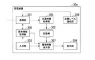
図4は、第1の実施形態における管理装置30の機能構成の具体例を示す図である。管理装置30は、バスで接続されたCPUやメモリや補助記憶装置などを備え、管理装置プログラムを実行する。管理装置30は、管理装置プログラムの実行によって通信部301、記憶部302、入力部303、表示部304、共通情報取得部305、固有情報取得部306及び管理情報表示部307を備える装置として機能する。なお、管理装置30の各機能の全て又は一部は、ASICやPLDやFPGA等のハードウェアを用いて実現されてもよい。管理装置プログラムは、コンピュータ読み取り可能な記録媒体に記録されてもよい。コンピュータ読み取り可能な記録媒体とは、例えばフレキシブルディスク、光磁気ディスク、ROM、CD−ROM等の可搬媒体、コンピュータシステムに内蔵されるハードディスク等の記憶装置である。管理装置プログラムは、電気通信回線を介して送信されてもよい。 FIG. 4 is a diagram showing a specific example of a functional configuration of the
通信部301は、管理装置30がバックボーンネットワーク網10に接続するための通信インターフェースを含んで構成される。 The
記憶部302は、磁気ハードディスク装置や半導体記憶装置などの記憶装置を用いて構成される。記憶部302は、ネットワーク管理情報を記憶する。 The
入力部303は、マウスやキーボード、タッチパネル等の入力装置を用いて構成される。入力部303は、自装置に対する操作の入力を受け付ける。 The
表示部304は、CRT(Cathode Ray Tube)ディスプレイや液晶ディスプレイ、有機EL(Electro-Luminescence)ディスプレイ等の表示装置を用いて構成される。 The
共通情報取得部305は、統合ゲートウェイ20から継続的に送信されてくる共通情報を取得する。具体的には、共通情報取得部305は、統合ゲートウェイ20の共通情報送信部208と共通プロトコルで通信することによって共通情報を取得する。共通情報取得部305は、取得した共通情報に基づいて、記憶部302に記憶されたネットワーク管理情報を更新する。 The common
固有情報取得部306は、統合ゲートウェイ20に対して固有情報の送信要求を送信することによって、統合ゲートウェイ20から固有情報を取得する。固有情報取得部306が固有情報の送信要求を送信するタイミングはどのようなタイミングであってもよい。例えば、固有情報取得部306は、ある個別ネットワーク網50に関する固有情報の表示操作が入力された場合に、入力情報が示す統合ゲートウェイ20に対して固有情報の送信要求を送信する。 The unique
管理情報表示部307は、入力部303を介して自装置に入力されるネットワーク管理情報の表示操作に応じて、記憶部302に記憶されたネットワーク管理情報を可視化し、表示部304に表示させる。 The management
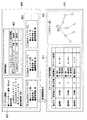
図5、図6及び図7は、ネットワーク管理情報の具体例を説明する図である。図5は、通信システム1の構成の具体例を示し、図6は、図5の具体例の通信システム1において保持されるネットワーク管理情報の具体例を示す。まず、図5の構成例について説明する。図5の例の通信システム1は、バックボーンネットワーク網10に接続する統合ゲートウェイ20として、ZigBee(登録商標)で通信する端末40−B1〜40−B7のアクセスリンクを統合する統合ゲートウェイ20Bと、Wi−Fi(登録商標)で通信する端末40−W1及び40−W2のアクセスリンクを統合する統合ゲートウェイ20Wとを有する。 5, 6, and 7 are diagrams for explaining specific examples of network management information. FIG. 5 shows a specific example of the configuration of the communication system 1, and FIG. 6 shows a specific example of network management information held in the communication system 1 of the specific example of FIG. First, the configuration example of FIG. 5 will be described. The communication system 1 in the example of FIG. 5 includes, as an
統合ゲートウェイ20B及び20Wは、それぞれが収容する端末40から端末情報を収集する。統合ゲートウェイ20B及び20Wは、収集された端末情報に基づいて共通情報及び固有情報を生成する。一方で、統合ゲートウェイ20B及び20Wは、各端末40の通信状況を監視し、各アクセスリンクの品質情報を生成する。統合ゲートウェイ20B及び20Wは、生成した品質情報を共通情報に含め、管理装置30と共通プロトコルで通信することにより共通情報を管理装置30に送信する。 The
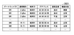
例えば、統合ゲートウェイ20B及び20Wから送信された共通情報は、管理装置30において、図6に示す共通情報テーブル3021として記憶される。共通情報テーブル3021は、ゲートウェイIDごとに複数の共通情報レコードを有する。共通情報レコードは、ゲートウェイID、通信種別、端末ID、IPアドレス、通信品質及び機器状態の各値を有する。ゲートウェイIDは、共通情報を送信した統合ゲートウェイ20B又は20Wの識別情報である。通信種別は、ゲートウェイIDが示す統合ゲートウェイ20B又は20Wに収容されるアクセスリンクの種別を表す。端末IDは、統合ゲートウェイ20B又は20Wに収容される各アクセスリンクに接続された端末40の識別情報である。IPアドレスは、端末IDが示す端末40のIP(Internet Protocol)アドレスである。通信品質は、共通情報に含まれる品質情報によって示される各アクセスリンクにおける通信品質を表す。機器状態は、端末IDが示す端末40の状態を表す。 For example, the common information transmitted from the
図6の例において、統合ゲートウェイ20BのゲートウェイIDは“GW1”で表され、統合ゲートウェイ20WのゲートウェイIDは“GW2”で表される。また、図6の例において、端末40−Bn(nは1以上の整数)の端末IDは、“端末Bn”で表される。そのため、ゲートウェイID“GW1”に対応する通信種別が“ZigBee(登録商標)”となっており、ゲートウェイID“GW2”に対応する通信種別は“Wi−Fi(登録商標)”となっている。 In the example of FIG. 6, the gateway ID of the
なお、統合ゲートウェイ20が管理装置30に対して共通情報を送信する際に用いられる共通プロトコルは、共通情報レコードが有する各項目に対応したデータフォーマットを有する。 The common protocol used when the
また、統合ゲートウェイ20B及び20Wによって生成された固有情報は、図7に示す固有情報テーブル3022−1や固有情報テーブル3022−2として各統合ゲートウェイ20B及び20Wにおいて記憶される。固有情報テーブル3022−1は、統合ゲートウェイ20Bにおいて記憶される固有情報の例である。固有情報テーブル3022−1は、端末IDごとの固有情報レコードを有する。固有情報レコードは、端末ID、受信電力、再送回数、接続構成、デバイス種別等の各値を有する。端末IDは、端末情報を送信した端末40の識別情報である。受信電力は、端末IDの示す端末40が無線信号の受信に要する電力を表す。再送回数は、端末IDの示す端末40の通信において再送が発生した回数を表す。接続構成は、端末IDが示す端末40と他の装置との接続構成を示す情報である。デバイス種別は、端末IDが示す端末40が個別ネットワーク網50におけるどのような端末であるかを示す情報である。図7の例は、端末40−B1(端末B1)及び端末40−B2(端末B2)がルーターであり、端末40−B3(端末B3)がネットワークのエッジに位置する端末であることを示している。 The unique information generated by the
また、固有情報テーブル3022−2は、統合ゲートウェイ20Wにおいて記憶される固有情報の例である。固有情報テーブル3022−2は、端末IDごとの固有情報レコードを有する。固有情報レコードは、端末ID、受信電力、再送回数、接続構成、使用チャネル、接続モード等の各値を有する。端末ID、受信電力、再送回数、接続構成は、固有情報テーブル3022−1と同様である。使用チャネルは、端末IDが示す端末40の無線通信に用いられる周波数チャネルを表す。接続モードは、端末IDが示す端末40が無線ネットワークに接続する態様を表す。一般に、Wi−Fi(登録商標)等の無線LAN(Local Area Network)に接続する態様には、アドホックモードやインフラストラクチャモード等の態様がある。接続モードは、このような接続の態様を表す情報である。 The unique information table 3022-2 is an example of unique information stored in the
なお、以上説明した固有情報テーブル3022−1及び3022−2は、固有情報の一例であり、固有情報には、個別ネットワーク網50に関して取得可能な情報であれば他のどのような情報が含まれてもよい。 The unique information tables 3022-1 and 3022-2 described above are an example of unique information, and the unique information includes any other information that can be acquired for the individual network 50. May be
図8は、ネットワーク管理情報が表示される態様の一例を示す図である。例えば、ネットワーク管理情報は、表示画面400と、表示画面410との態様で表示部304に表示される。表示画面400は、共通情報に含まれる情報に基づいて表示される画面であり、表示画面410は、固有情報に含まれる情報に基づいて表示される画面である。表示画面400は、システム情報表示領域401、障害警報表示領域402及び個別ネットワーク網50ごとの管理情報表示領域403を有する。また、表示画面410は、固有情報表示領域411及び接続構成表示領域412を有する。例えば、管理装置30の固有情報取得部306は、表示画面400の表示中において、いずれかの個別ネットワーク網50について詳細を表示させる操作が入力されたタイミングで、表示対象の統合ゲートウェイ20から固有情報を取得する。固有情報取得部306は、取得した固有情報を管理情報表示部307に出力する。管理情報表示部307は、固有情報取得部306から出力された固有情報に基づいて表示画面410を生成し、表示部304に表示させる。 FIG. 8 is a diagram showing an example of an aspect in which network management information is displayed. For example, the network management information is displayed on the
このような表示画面400及び410の表示により、管理装置30は、通信システム1が有する個別ネットワーク網50に関する情報を視覚的に認識可能な態様で利用者に提供することができる。通信システム1に関する情報がこのように視覚的に認識可能な態様で提供されることにより、通信システム1の管理者はネットワークの状態をより容易に把握することが可能となる。 The display of
なお、接続構成表示領域412には、ネットワークの接続構成を示すトポロジー図4121が表示されてもよい。この場合、管理情報表示部307は、固有情報に含まれる接続構成を示す情報に基づいて、トポロジー図4121を生成可能である。なお、図8に示した表示画面400及び410は、ネットワーク管理情報を表示する態様の一例であり、共通情報又は個別情報に基づいて生成可能であれば、他のどのような態様で表示されてもよい。例えば、トポロジー図4121に示された各端末40に、各端末40の状態を示す情報が重畳して表示されてもよい。また、トポロジー図4121は、各端末40の物理的な接続構成を示すものであってもよいし、論理的な接続構成を示すものであってもよい。 Note that, in the connection
図9は、物理的な接続構成を示すトポロジー図及び論理的な接続構成を示すトポロジー図を説明する図である。図9(A)は、あるフロア500における端末40−51〜40−57の配置を示す図である。図9(B)は、フロア500に設置された端末40−51〜40−57の物理的な接続構成を示すトポロジー図である。図9(B)に示すトポロジー図は、各端末40の接続構成の表示において、各端末40の表示位置をフロア500における各端末40の位置関係に対応する位置とすることによって得られる。このような物理的な接続構成を示すトポロジー図の表示には、各端末40の配置位置を示す位置情報が必要となる。この場合、例えば、管理装置30の記憶部302に各端末40の位置情報を予め記憶させておく。管理情報表示部307は、固有情報に基づいて生成したトポロジー図の表示において、トポロジー図を構成する各端末40を、位置情報により得られる各端末40の位置関係に応じた位置に表示させる。物理的な接続構成を示すトポロジー図の表示には、各端末40が配置された空間の地図が重畳されてもよい。 FIG. 9 is a diagram for explaining a topology diagram showing a physical connection configuration and a topology diagram showing a logical connection configuration. FIG. 9A shows an arrangement of terminals 40-51 to 40-57 on a
これに対して図9(C)は、フロア500に設置された端末40−51〜40−57の論理的な接続構成を示すトポロジー図である。図9(C)に示すトポロジー図は、各端末40の接続構成の表示において、各端末40の表示位置を各端末40の親子関係に対応する位置とすることによって得られる。管理情報表示部307は、自装置が各端末40の位置情報を記憶していない場合においては、物理的な接続構成を示すトポロジー図に代えて論理的な接続構成を示すトポロジー図を表示させるように構成されてもよい。また、管理情報表示部307は、利用者の操作に応じて、物理的な接続構成を示すトポロジー図と、論理的な接続構成を示すトポロジー図と、の表示を切り替えるように構成されてもよい。 On the other hand, FIG. 9C is a topology diagram showing a logical connection configuration of the terminals 40-51 to 40-57 installed on the
図10及び図11は、第1の実施形態の通信システム1におけるネットワーク管理情報の収集の流れを示すシーケンス図である。まず、統合ゲートウェイ20は、システム起動時において初期化処理を行う(ステップS101)。統合ゲートウェイ20は、この初期化処理において、自装置に接続されたインターフェースユニットに応じてソフトウェア更新を行う。このソフトウェア更新によって、統合ゲートウェイ20は、下位側のアクセスリンクの通信プロトコルと、上位側のアクセスリンクの通信プロトコルとを相互に変換するゲートウェイ装置として起動する。初期化処理を完了後、統合ゲートウェイ20は、自装置の識別情報と、自装置が収容可能なアクセスリンクの種別を示す情報と、を含む初期登録通知を管理装置30に送信する(ステップS102)。 10 and 11 are sequence diagrams showing a flow of collection of network management information in the communication system 1 of the first embodiment. First, the
管理装置30は、統合ゲートウェイ20から送信された初期登録通知を受信する(ステップS103)。管理装置30は、取得した初期登録通知に基づいて、初期登録通知を送信した統合ゲートウェイ20を自装置に登録する(ステップS104)。以下、この統合ゲートウェイ20の登録を初期登録と記載する。管理装置30は、初期登録が完了したことを示す初期登録完了通知を、初期登録通知の送信元の統合ゲートウェイ20に送信する(ステップS105)。統合ゲートウェイ20は、初期登録完了通知を受信する(ステップS106)。統合ゲートウェイ20は、初期登録完了通知の受信を契機として、端末40から送信される接続要求の受付を開始する(ステップS107)。例えば、統合ゲートウェイ20は、初期登録完了通知の受信を契機として、自装置の存在を通知するためのビーコン信号の送信を開始する。 The
一方、端末40は、統合ゲートウェイ20から送信されたビーコン信号を検地し、ビーコン信号の送信元の統合ゲートウェイ20に対して接続要求を送信する(ステップS108)。統合ゲートウェイ20は、端末40から送信された接続要求を受信する(ステップS109)。統合ゲートウェイ20は、当該端末40を自装置に収容可能であるか否かを判定し、収容可能と判定した場合に、当該端末40に対して接続許可通知を送信する(ステップS110)。例えば、この接続可否の判定は、自装置のリソース(例えば、自装置に収容可能な端末数など)の状況に基づいて判定されてもよいし、当該端末40が自装置に接続する資格を有するか否かなどによって判定されてもよい。 On the other hand, the terminal 40 detects the beacon signal transmitted from the integrated
端末40は、統合ゲートウェイ20から送信された接続許可通知を受信する(ステップS111)。この接続許可応答の受信を契機として、端末40は統合ゲートウェイ20と通信可能な状態となる。 The terminal 40 receives the connection permission notice transmitted from the integration gateway 20 (step S111). The terminal 40 can communicate with the
端末40は、統合ゲートウェイ20と通信可能な状態になると、統合ゲートウェイ20に対して端末情報を送信する(ステップS112)。統合ゲートウェイ20は、端末40から送信された端末情報を受信する(ステップS113)。一方で、統合ゲートウェイ20は、端末40との間の通信に基づいて品質情報を取得する(ステップS114)。統合ゲートウェイ20は、取得した端末情報及び品質情報を、管理装置30に送信する共通情報と、自装置に記憶する固有情報とに分類する(ステップS115)。 When the terminal 40 can communicate with the
統合ゲートウェイ20は、取得した固有情報を自装置に記憶する(ステップS116)。一方で、統合ゲートウェイ20は、取得した共通情報を管理装置30に送信する(ステップS117)。管理装置30は、統合ゲートウェイ20から送信された共通情報を受信する(ステップS118)。具体的には、統合ゲートウェイ20は、取得した共通情報を送信するための共通情報送信メッセージを共通プロトコルに則って生成する。統合ゲートウェイ20は、生成した共通情報送信メッセージを管理装置30に送信する。管理装置30は、統合ゲートウェイ20と共通プロトコルで通信することにより、共通情報送信メッセージを受信する。 The
管理装置30は、統合ゲートウェイ20から取得した共通情報で、自装置に記憶されている共通情報を更新する(ステップS119)。 The
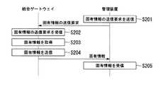
図12は、管理装置30が統合ゲートウェイ20から固有情報を取得する流れを示すシーケンス図である。管理装置30が固有情報を取得するタイミングは、管理装置30において固有情報が必要となったタイミングである。例えば、管理装置30において固有情報の取得が必要となるタイミングは、固有情報の表示を指示する操作が入力された場合である。 FIG. 12 is a sequence diagram showing a flow in which the
このような取得タイミングが到来した場合、管理装置30は、まず、必要とする固有情報を保持する統合ゲートウェイ20に対して、固有情報の送信要求を送信する(ステップS201)。統合ゲートウェイ20は、管理装置30から送信された固有情報の送信要求を受信する(ステップS202)。統合ゲートウェイ20は、自装置の記憶部203に記憶されている固有情報を取得する(ステップS203)。統合ゲートウェイ20は、取得した固有情報を管理装置30に送信する(ステップS204)。 When such an acquisition timing arrives, the
具体的には、統合ゲートウェイ20は、自装置に記憶している固有情報に基づいて、固有情報を送信するための送信メッセージを所定のプロトコルに則って生成する。統合ゲートウェイ20は、生成した通知メッセージを管理装置30に送信する。管理装置30は、統合ゲートウェイ20から送信された通知メッセージを受信する。統合ゲートウェイ20は、取得した通知メッセージに基づいて、指示された固有情報の表示を行う。 Specifically, the
なお、ここでは、管理装置30は、自装置に対する固有情報の表示操作の入力に応じて統合ゲートウェイ20から固有情報を取得する構成について説明した。これは固有情報を、各統合ゲートウェイ20に分散して保持させることによって、ネットワーク管理情報の収集によってアクセスリンクの通信帯域が圧迫されないようにすることを目的としたものである。その意味では、管理装置30は、通信帯域を圧迫しない程度の更新頻度を条件として、固有情報を自装置に記憶するように構成されてもよい。この場合、管理装置30は、所定の更新タイミングが到来したタイミングで、固有情報の取得要求を統合ゲートウェイ20に送信する。管理装置30は、取得要求に応じて送信される通知メッセージに基づいて、自装置に記憶する固有情報を更新する。 In addition, the
このように構成された第1の実施形態の通信システム1では、ネットワーク管理に必要な情報は、全てのアクセスリンクで共通の共通管理情報と、各アクセスリンクで固有の固有情報とに分類され、各統合ゲートウェイ20及び管理装置30に分散して保持される。管理装置30は、各ゲートウェイ装置から、共通管理情報を継続的に収集し、固有情報を必要に応じて取得する。このような構成を備えることにより、通信システム1は、多種多様なアクセスリンクに関する管理情報を、効率的に収集することが可能となる。 In the communication system 1 of the first embodiment configured as described above, information necessary for network management is classified into common management information common to all access links and unique information unique to each access link, It is distributed and held in each
また、第1の実施形態における統合ゲートウェイ20は、複数の通信プロトコルに対応可能な第2通信部202を備える。統合ゲートウェイ20が、このような第2通信部202を備えることにより、異なるアクセスリンクの追加又は削除を容易に行うことができる。 Further, the
(第2の実施形態)
第2の実施形態の通信システム1は、統合ゲートウェイ20に代えて統合ゲートウェイ20aを備える点、管理装置30に代えて管理装置30aを備える点で、第1の実施形態の通信システム1と異なる。
図13は、第2の実施形態における統合ゲートウェイ20aの機能構成の具体例を示す図である。統合ゲートウェイ20aは、共通情報送信部208に代えて共通情報送信部208aを備える点、固有情報送信部209に代えて固有情報送信部209aを備える点で、第1の実施形態における統合ゲートウェイ20と異なる。Second Embodiment
The communication system 1 of the second embodiment differs from the communication system 1 of the first embodiment in that it includes an
FIG. 13 is a diagram showing a specific example of a functional configuration of the
共通情報送信部208aは、管理装置30aから通知される送信レベルに基づいて、共通情報を管理装置30aに送信する。送信レベルは、統合ゲートウェイ20aから単位時間当たりに送信される共通情報又は固有情報の情報量を制限するための情報である。送信レベルは、管理装置30aによって決定され、統合ゲートウェイ20aに通知される。例えば、送信レベルは、共通情報又は固有情報に含められる情報の種別を示す情報である。共通情報送信部208aは、送信レベルによって指定された種別の情報を共通情報として管理装置30aに送信する。固有情報送信部209aも同様に、送信レベルによって指定された種別の情報を固有情報として管理装置30aに送信する。送信レベルは、情報種別の指定に限らず、送信される情報量を調整することが可能あれば、他のどのような内容を通知するものであってもよい。例えば、送信レベルとして、情報の送信頻度や送信タイミング等が指定されてもよい。 The common
図14は、第2の実施形態における管理装置30aの機能構成の具体例を示す図である。管理装置30aは、送信レベル通知部308をさらに備える点で、第1の実施形態における管理装置30と異なる。
送信レベル通知部308は、送信レベルを決定して統合ゲートウェイ20aに通知する。送信レベル通知部308は、所定のタイミングごとに送信レベルを決定して通知してもよいし、送信レベルの変更が必要となった場合にのみ通知するように構成されてもよい。FIG. 14 is a diagram showing a specific example of the functional configuration of the management device 30a in the second embodiment. The management device 30a differs from the
The transmission
図15は、送信レベルの変更に応じた固有情報の変化の具体例を示す図である。大規模な通信システムでは、端末数が膨大であったり、ネットワーク上を大量のトラフィックが占有している場合がある。そのような条件下ではネットワーク管理情報の送受信がネットワークの輻輳を招く可能性がある。そのため、管理装置30aは、システム規模の変化やネットワークの負荷状態を監視し、システム規模やネットワークの負荷状態に応じた送信レベルを決定し、統合ゲートウェイ20に通知する。このような送信レベルの通知により、ネットワークの負荷が増大することを抑制することができる。 FIG. 15 is a diagram showing a specific example of the change of the unique information according to the change of the transmission level. In a large-scale communication system, the number of terminals may be huge, or a large amount of traffic may be occupied on the network. Under such conditions, transmission and reception of network management information may lead to network congestion. Therefore, the management device 30a monitors a change in system size and the load condition of the network, determines a transmission level according to the system size and the load condition of the network, and notifies the integrated
例えば、図15は、3段階の送信レベルが定義された場合の例である。このように、通信システム1における端末数の増加や、ネットワーク負荷の高騰に応じて、より少ない情報を送信するように送信レベルが変更される。なお、送信レベルを決定する基準には、端末数やネットワークの負荷以外の情報が用いられてもよい。なお、送信レベルは、共通情報又は固有情報のいずれか一方の送信に対して通知されてもよい。 For example, FIG. 15 shows an example in which three transmission levels are defined. As described above, the transmission level is changed to transmit less information according to the increase in the number of terminals in the communication system 1 and the increase in the network load. Information other than the number of terminals and the load of the network may be used as a criterion for determining the transmission level. The transmission level may be notified for either transmission of common information or specific information.
図16及び図17は、第2の実施形態におけるネットワーク管理情報の収集の流れを示すシーケンス図である。なお、図16及び図17のシーケンス図に示す処理のうち、図10及び図11のシーケンス図と同様の処理については、図10及び図11と同様の符号を付すことにより説明を省略する。なお、ここでは、固有情報の送信に対して送信レベルが通知されると仮定する。 16 and 17 are sequence diagrams showing the flow of collection of network management information in the second embodiment. Among the processes shown in the sequence diagrams of FIGS. 16 and 17, the processes similar to those of the sequence diagrams of FIGS. 10 and 11 will not be described by giving the same reference numerals as those of FIGS. 10 and 11. Here, it is assumed that the transmission level is notified for the transmission of the unique information.
管理装置30aは、ステップS119において共通情報の更新を行うと、固有情報の送信レベルを変更するか否かを判定する(ステップS301)。この判定は、送信レベル通知部308によって行われる。例えば、送信レベルとして、第1送信レベル、第2送信レベル及び第3送信レベルが定義されていると仮定する。各送信レベルは、第1送信レベル、第2送信レベル、第3送信レベルの順に大きな情報量の固有情報を要求する送信レベルである。そして、通常時においては、第2送信レベルで固有情報が送信されると仮定する。 After updating the common information in step S119, the management device 30a determines whether to change the transmission level of the unique information (step S301). This determination is performed by the transmission
例えば、送信レベルを変更するか否かの判定は、共通情報を更新したタイミングでの総端末数に基づいて判定される。総端末数は、バックボーンネットワーク網10に接続された全ての統合ゲートウェイ20aに収容されている端末40の総数である。例えば、送信レベル通知部308は、総端末数が所定の第1閾値を超えた場合に、第2送信レベルを第1送信レベルに変更することを判定する。一方で、送信レベル通知部308は、総端末数が所定の第2閾値を下回った場合に、第2通信レベルを第3通信レベルに変更することを判定する。また、総端末数が第1閾値以下でありかつ第2閾値以上である場合には、送信レベル通知部308は、送信レベルを第2送信レベルから変更しないことを判定する。 For example, the determination as to whether or not to change the transmission level is made based on the total number of terminals at the timing at which the common information is updated. The total number of terminals is the total number of
送信レベルを変更しないことが判定された場合(ステップS301−NO)、管理装置30aは、本シーケンスにおける処理を終了し、次の共通情報の受信を待機する。一方、送信レベルを変更することが判定された場合(ステップS301−YES)、送信レベル通知部308は、変更後の送信レベルを示す送信レベル通知を統合ゲートウェイ20に通知する(ステップS302)。統合ゲートウェイ20aは、送信レベル通知を受信する(ステップS303)。統合ゲートウェイ20aは、受信した通信レベル通知によって通知された送信レベルを記憶する(ステップS304)。統合ゲートウェイ20aは、以後の共通情報の送信を通知された送信レベルで実行する。 If it is determined that the transmission level is not to be changed (NO in step S301), the management device 30a ends the process in this sequence and waits for the next common information to be received. On the other hand, when it is determined that the transmission level is to be changed (YES in step S301), the transmission
このように構成された第2の実施形態の通信システム1では、管理装置30aが、通信システム1の状態に応じて共通情報の送信レベルを各統合ゲートウェイ20aに通知する。統合ゲートウェイ20aは、管理装置30aによって通知された送信レベルで共通情報の送信を行う。すなわち、第2の実施形態の通信システム1は、システムの状態に応じた情報量で、共通情報を取得することができる。このような機能を備えることにより、第2の実施形態の通信システム1は、ネットワーク管理情報の取得をより効率的に行うことが可能となる。 In the communication system 1 of the second embodiment configured as described above, the management device 30a notifies each
以下、実施形態の通信システム1の変形例について説明する。
共通情報の送信は、端末40の新規接続、撤去といった端末40に関するイベントの発生に応じて行われてもよいし、通信品質がある一定の閾値以下となった端末40の検出に応じて行われてもよい。このようなタイミングで共通情報を送信することにより、ネットワークのトラフィック量をより削減することが可能となる。Hereinafter, modifications of the communication system 1 according to the embodiment will be described.
The transmission of the common information may be performed in response to the occurrence of an event related to the terminal 40 such as new connection or removal of the terminal 40, or is performed in response to detection of the terminal 40 whose communication quality has fallen below a certain threshold. May be By transmitting the common information at such timing, it is possible to further reduce the traffic volume of the network.
共通情報及び固有情報として送信される情報は、ネットワーク管理情報に限定されない。上述した共通情報及び固有情報の送信方法は、通信システムにおけるネットワーク管理情報以外の情報の送信に適用されてもよい。 Information transmitted as common information and specific information is not limited to network management information. The transmission method of the common information and the unique information described above may be applied to transmission of information other than the network management information in the communication system.
以上説明した少なくともひとつの実施形態によれば、端末40から取得される情報を共通情報と固有情報とに分類し、共通情報を管理装置30に送信し、固有情報を自装置に記憶する統合ゲートウェイ20と、所定のタイミングにおいて統合ゲートウェイ20から固有情報を取得する管理装置30と、を持つことにより、異なる通信プロトコルが混在する通信システムにおいて、ネットワークの管理にかかる負荷を低減することができる。 According to at least one embodiment described above, an integrated gateway that classifies information acquired from the terminal 40 into common information and unique information, transmits the common information to the
本発明のいくつかの実施形態を説明したが、これらの実施形態は、例として提示したものであり、発明の範囲を限定することは意図していない。これら実施形態は、その他の様々な形態で実施されることが可能であり、発明の要旨を逸脱しない範囲で、種々の省略、置き換え、変更を行うことができる。これら実施形態やその変形は、発明の範囲や要旨に含まれると同様に、特許請求の範囲に記載された発明とその均等の範囲に含まれるものである。 While certain embodiments of the present invention have been described, these embodiments have been presented by way of example only, and are not intended to limit the scope of the invention. These embodiments can be implemented in other various forms, and various omissions, replacements, and modifications can be made without departing from the scope of the invention. These embodiments and modifications thereof are included in the invention described in the claims and the equivalents thereof as well as included in the scope and the gist of the invention.
1…通信システム、10…バックボーンネットワーク網、20,20a,20B,20W,20−1〜20−3…(アクセスリンク)統合ゲートウェイ、201…第1通信部、202…第2通信部、203…記憶部、204…中継処理部、205…品質情報取得部、206…端末情報取得部、207…端末情報分類部、208,208a…共通情報送信部、209,209a…固有情報送信部、30,30a…管理装置、301…通信部、302…記憶部、3021…共通情報テーブル、3022−1,3022−2…固有情報テーブル、303…入力部、304…表示部、305…共通情報取得部、306…固有情報取得部、307…管理情報表示部、308…送信レベル通知部、40,40−11〜40−13,40−21〜40−23,40−31〜40−33,40−B1〜40−B7,40−W1,40−W2…端末、50,50−1〜50−3…個別ネットワーク網、60−1,60−11〜60−13,60−2,60−21〜60−23,60−31〜60−33…アクセスリンク、70,70−1〜70−n…インターフェースユニット、71…プロトコル処理部、400…表示画面、401…システム情報表示領域、402…障害警報表示領域、403…管理情報表示領域、410…表示画面、411…固有情報表示領域、412…接続構成表示領域、4121…トポロジー図、500…フロアDESCRIPTION OF SYMBOLS 1 ... Communication system, 10 ... Backbone network network, 20, 20a, 20B, 20W, 20-1-20-3 ... (Access link) integrated gateway, 201 ... 1st communication part, 202 ... 2nd communication part, 203 ... Storage unit 204 Relay processing unit 205 Quality information acquisition unit 206 Terminal information acquisition unit 207 Terminal information classification unit 208, 208a Common information transmission unit 209, 209a Unique information transmission unit 30, 30a management device, 301 communication unit, 302 storage unit, 3021 common information table 3022-1, 3022-2 unique information table 303 input unit 304 display unit 305 common information acquisition unit 306: Unique information acquisition unit, 307: Management information display unit, 308: Transmission level notification unit, 40, 40-11 to 40-13, 40-21 to 40-23 40-31 to 40-33, 40-B1 to 40-B7, 40-W1, 40-W2 terminals, 50, 50-1 to 50-3 individual networks, 60-1, 60-11 to 60- 13, 60-2, 60-21 to 60-23, 60-31 to 60-33: access link, 70, 70-1 to 70-n: interface unit, 71: protocol processing unit, 400: display screen, 401 ... system information display area, 402 ... fault alarm display area, 403 ... management information display area, 410 ... display screen, 411 ... unique information display area, 412 ... connection configuration display area, 4121 ... topology diagram, 500 ... floor ...
Claims (14)
Translated fromJapanese前記機器情報を、全ての前記機器の機器情報に含まれる第1情報と、前記第1情報と異なる第2情報と、に分類する機器情報分類部と、
前記機器情報分類部によって分類された前記第1情報を、前記管理装置の要求の有無によらず前記管理装置に送信する第1情報送信部と、
前記機器情報分類部によって分類された前記第2情報を、前記管理装置の要求があった場合に前記管理装置に送信する第2情報送信部と、
を備える通信装置。A communication device thatis used in a communication system having a management device that acquires device information on a deviceto be managed, and transmits the device information to the management device,
A device information classification unit that classifies the device information intofirst informationincluded in the device information of all the devicesand second informationdifferent from the first information ;
A first information transmission unit that transmits the first information classified by the device information classification unit to the management device regardless of the presence or absence of a request from the management device;
Asecond information transmitting unit transmitting thesecond information which is classified by the device information classifying unit, to the management device when requested by the management device,
A communication device comprising
前記通信部は、接続された前記機器に応じて通信プロトコルを切り替える、
請求項1に記載の通信装置。The communication device further includes a communication unit that connects the device to the device.
The communication unit switches a communication protocol according to the connected device.
The communication device according to claim 1.
前記機器情報分類部は、前記品質情報を前記第1情報に分類する、
請求項1又は2に記載の通信装置。It further comprises a quality information acquisitionunit that acquires quality information indicating the quality regarding communication of the device,
The device information classification unit classifies the quality information intothe first information.
The communication device according to claim 1.
請求項3に記載の通信装置。The first information transmission unit orthe second information transmission unit transmitsthe first information orthe second information to the management device when there is a change in the state of the network or the device of the communication system.
The communication device according to claim 3.
請求項1から4のいずれか一項に記載の通信装置。The communication device according to any one of claims 1 to 4.
前記通信装置に係る機器であって自装置の管理対象となる機器に関する機器情報のうち、全ての前記機器の機器情報に含まれる第1情報と異なる第2情報を必要に応じて前記通信装置から取得する管理装置と、
を備える通信システム。The communication device according to any one of claims 1 to5 .
Among the device information related to the device to be managed by the own device, which is a device related to the communication device,second informationdifferent from thefirst informationincluded in the device information of all the devices from the communication device as necessary Management device to acquire,
A communication system comprising
請求項6に記載の通信システム。The management device includes a management information display unit which causes the display device capable of displaying information to displaythe first information andthe second information.
The communication system according to claim6 .
請求項7に記載の通信システム。The management information display unit generates a diagram showing the connection configuration of the device based onthe first information orthe second information and causes the display device to display a diagram.
The communication system according to claim7 .
前記通信装置は、単位時間当たりに送信する前記第1情報又は前記第2情報の情報量が前記管理装置から通知された前記送信レベルに応じた情報量となるように、前記第1情報又は前記第2情報を送信する、
請求項6から8のいずれか一項に記載の通信システム。The management device further includes a transmission level notification unit that notifies the communication device of a transmission level that limits the amount of information ofthe first information orthe second information transmitted from the communication device per unit time,
The communication device, as the amount of information of thefirst information or thesecond information transmitted per unit time is the amount of information corresponding to the transmission level notified from the management apparatus, thefirst information or the Sendthe second information,
The communication system according to any one of claims6 to 8 .
請求項9に記載の通信システム。The transmission level notification unit determines a transmission level to be notified to the communication device based on the number of the devices related to the communication device.
The communication system according to claim9 .
請求項9又は10に記載の通信システム。The transmission level notification unit determines the transmission level to be notified to the communication device based on the amount of traffic related to the communication device.
A communication system according to claim9 or 10 .
請求項9から11のいずれか一項に記載の通信システム。The transmission level notification unit determines a transmission level to be notified to the communication device based on the number of the communication devices.
The communication system according to any one of claims9 to 11 .
請求項9から12のいずれか一項に記載の通信システム。The transmission level is information indicating transmission timing or transmission frequency ofthe first information orthe second information.
The communication system according to any one of claims9 to 12 .
前記通信装置が、
前記機器情報を、全ての前記機器の機器情報に含まれる第1情報と、前記第1情報と異なる第2情報と、に分類する機器情報分類ステップと、
前記機器情報分類ステップにおいて分類された前記第1情報を、前記管理装置の要求の有無によらず前記管理装置に送信する第1情報送信ステップと、
前記機器情報分類ステップにおいて分類された前記第2情報を、前記管理装置の要求があった場合に前記管理装置に送信する第2情報送信ステップと、
前記管理装置が、
前記通信装置に対して、前記第2情報の送信を要求するステップと、
を有するネットワーク管理方法。A network management method performed by a communication system comprising: the communication device according to any one of claims 1 to5 ; and a management device for acquiring device information on a device to be managed from the communication device,
The communication device is
A device information classification step of classifying the device information intofirst informationincluded in device information of all the devicesand second informationdifferent from the first information ;
A first information transmission step of transmitting the first information classified in the device information classification step to the management device regardless of the presence or absence of a request from the management device;
Thesecond information classified in the device information classification step, asecond information transmitting step of transmitting to said management device when requested by the management device,
The management device
Requesting the communication device to transmitthe second information;
Network management method.
Priority Applications (6)
| Application Number | Priority Date | Filing Date | Title |
|---|---|---|---|
| JP2015256703AJP6514100B2 (en) | 2015-12-28 | 2015-12-28 | Communication apparatus, communication system and network management method |
| EP16881701.3AEP3399693A4 (en) | 2015-12-28 | 2016-12-22 | Communication apparatus, communication system, and network management method |
| KR1020187017670AKR102062604B1 (en) | 2015-12-28 | 2016-12-22 | Communication devices, communication systems, and network management methods |
| CN201680076402.7ACN108432182A (en) | 2015-12-28 | 2016-12-22 | Communication device, communication system, and network management method |
| PCT/JP2016/088447WO2017115726A1 (en) | 2015-12-28 | 2016-12-22 | Communication apparatus, communication system, and network management method |
| US16/018,906US20180309856A1 (en) | 2015-12-28 | 2018-06-26 | Communication device, communication system, and network management method |
Applications Claiming Priority (1)
| Application Number | Priority Date | Filing Date | Title |
|---|---|---|---|
| JP2015256703AJP6514100B2 (en) | 2015-12-28 | 2015-12-28 | Communication apparatus, communication system and network management method |
Publications (2)
| Publication Number | Publication Date |
|---|---|
| JP2017120987A JP2017120987A (en) | 2017-07-06 |
| JP6514100B2true JP6514100B2 (en) | 2019-05-15 |
Family
ID=59224972
Family Applications (1)
| Application Number | Title | Priority Date | Filing Date |
|---|---|---|---|
| JP2015256703AActiveJP6514100B2 (en) | 2015-12-28 | 2015-12-28 | Communication apparatus, communication system and network management method |
Country Status (6)
| Country | Link |
|---|---|
| US (1) | US20180309856A1 (en) |
| EP (1) | EP3399693A4 (en) |
| JP (1) | JP6514100B2 (en) |
| KR (1) | KR102062604B1 (en) |
| CN (1) | CN108432182A (en) |
| WO (1) | WO2017115726A1 (en) |
Families Citing this family (2)
| Publication number | Priority date | Publication date | Assignee | Title |
|---|---|---|---|---|
| EP4089979B1 (en)* | 2018-06-15 | 2024-12-11 | Nippon Telegraph and Telephone Corporation | Network management system, management device, relay device, method, and program |
| US20230098555A1 (en)* | 2021-09-27 | 2023-03-30 | International Business Machines Corporation | Ensuring data completeness using context aware machine learning models |
Family Cites Families (50)
| Publication number | Priority date | Publication date | Assignee | Title |
|---|---|---|---|---|
| US5426635A (en)* | 1993-09-08 | 1995-06-20 | At&T Corp. | Method for adaptive control of windows and rates in networks |
| JP2000244510A (en)* | 1999-02-18 | 2000-09-08 | Toshiba Corp | Network management method and network management device |
| EP1156631B1 (en)* | 1999-11-01 | 2017-02-15 | Panasonic Intellectual Property Corporation of America | Method and apparatus for information transmission |
| US6587125B1 (en)* | 2000-04-03 | 2003-07-01 | Appswing Ltd | Remote control system |
| GB2369911B (en)* | 2000-12-11 | 2002-10-23 | 3Com Corp | Methods and apparatus for updating information in a display containing fixed and variable information |
| US20040034638A1 (en)* | 2002-07-18 | 2004-02-19 | International Business Machines Corporation | Method for analyzing and characterizing the usage pattern of a device |
| TWI323101B (en)* | 2003-01-21 | 2010-04-01 | Panasonic Corp | Communication system and its terminal |
| JP4136857B2 (en) | 2003-09-11 | 2008-08-20 | キヤノン株式会社 | Device search method and program |
| JP4641714B2 (en)* | 2003-11-12 | 2011-03-02 | ソニー株式会社 | Remote monitoring system |
| US9537731B2 (en)* | 2004-07-07 | 2017-01-03 | Sciencelogic, Inc. | Management techniques for non-traditional network and information system topologies |
| WO2006014504A2 (en)* | 2004-07-07 | 2006-02-09 | Sciencelogic, Llc | Self configuring network management system |
| JP2006080615A (en)* | 2004-09-07 | 2006-03-23 | Nec Commun Syst Ltd | Network management method, apparatus and program |
| US7581000B2 (en)* | 2005-01-11 | 2009-08-25 | Ricoh Company, Ltd. | Monitoring device having a memory containing data representing access information configured to be used by multiple implementations of protocol access functions to extract information from networked devices |
| JP2007074234A (en)* | 2005-09-06 | 2007-03-22 | Hitachi Communication Technologies Ltd | Transmission equipment |
| JP4517997B2 (en)* | 2005-10-05 | 2010-08-04 | 株式会社日立製作所 | Network management apparatus and network system |
| US20070121525A1 (en)* | 2005-11-25 | 2007-05-31 | Dr. Per V. Jenster | Method and sytem for increasing bandwidth usage in a network |
| US8375205B2 (en)* | 2007-09-28 | 2013-02-12 | Intel Corporation | Techniques for communicating information over management channels |
| EP2109339B8 (en)* | 2007-12-12 | 2016-05-25 | Panasonic Intellectual Property Management Co., Ltd. | Data transmitting and receiving system, terminal, relay device, and data transmitting method |
| US8310932B2 (en)* | 2008-01-02 | 2012-11-13 | Thomson Licensing | System and method for sharing an access line bandwidth |
| US7929446B2 (en)* | 2008-01-04 | 2011-04-19 | Radiient Technologies, Inc. | Mesh networking for wireless communications |
| JP2009225329A (en)* | 2008-03-18 | 2009-10-01 | Toshiba Corp | Mobile communication system |
| JP2009253927A (en)* | 2008-04-11 | 2009-10-29 | Sony Corp | Network management apparatus, network management method, and monitoring system |
| CN101867565A (en)* | 2010-04-13 | 2010-10-20 | 中兴通讯股份有限公司 | General drive method and driver for mobile broadband equipment |
| US8504530B2 (en)* | 2010-06-26 | 2013-08-06 | Asibo Inc. | Global information management system and method |
| JP5782791B2 (en)* | 2011-04-08 | 2015-09-24 | 株式会社バッファロー | Management device, management method, program, and recording medium |
| US8660006B2 (en)* | 2011-11-29 | 2014-02-25 | Hughes Network Systems, Llc | Method and system for traffic management and resource allocation on a shared access network |
| JP6136217B2 (en)* | 2011-12-27 | 2017-05-31 | 株式会社リコー | Communication management system, communication system, program, and maintenance system |
| CN202956853U (en)* | 2012-08-21 | 2013-05-29 | 南车青岛四方机车车辆股份有限公司 | Train smoke and fire alarm system based on wireless sensor network |
| JP5904908B2 (en)* | 2012-08-30 | 2016-04-20 | 株式会社日立製作所 | Communication system and quality control server |
| CN103051672B (en)* | 2012-11-21 | 2016-02-10 | 中兴通讯股份有限公司 | End message acquisition methods in a kind of heterogeneous terminals environment and device |
| US9686165B2 (en)* | 2013-04-25 | 2017-06-20 | Control4 Corporation | Systems and methods for indicating link quality |
| US9872122B2 (en)* | 2013-08-22 | 2018-01-16 | Nec Corporation | Network information collection and analysis of a plurality of mobile networks |
| CN104519509A (en)* | 2013-09-29 | 2015-04-15 | 索尼公司 | Wireless network monitoring device in wireless communication system, method used in wireless communication system and device in wireless communication system |
| JP2015109029A (en)* | 2013-12-05 | 2015-06-11 | 株式会社日立産機システム | Device management system, communication device, and device management method |
| WO2015157200A1 (en)* | 2014-04-06 | 2015-10-15 | Hughes Network Systems, Llc | Apparatus and method for an adaptive periodic bandwidth allocation approach in a shared bandwidth communications system |
| US10158536B2 (en)* | 2014-05-01 | 2018-12-18 | Belkin International Inc. | Systems and methods for interaction with an IoT device |
| JP6771855B2 (en)* | 2014-06-02 | 2020-10-21 | ヤマハ株式会社 | Relay device and program |
| ES2793654T3 (en)* | 2014-08-21 | 2020-11-16 | Lg Electronics Inc | Method for uplink transmission in a wireless communication system and apparatus therefor |
| US10128925B2 (en)* | 2014-08-22 | 2018-11-13 | Lg Electronics Inc. | Method for uplink multi-user transmission in wireless communication system and apparatus therefor |
| RU2649298C1 (en)* | 2014-10-31 | 2018-03-30 | Нек Корпорейшн | Gateway device and method of its management |
| CN104468711B (en)* | 2014-10-31 | 2018-07-06 | 上海融军科技有限公司 | The general data management coding method of Internet of Things and system |
| US10542118B2 (en)* | 2015-09-24 | 2020-01-21 | Intel Corporation | Facilitating dynamic filtering and local and/or remote processing of data based on privacy policies and/or user preferences |
| US11129045B2 (en)* | 2015-12-08 | 2021-09-21 | Hitachi Kokusai Electric Inc. | Communication device and communication method |
| JP6399606B2 (en)* | 2016-07-12 | 2018-10-03 | Necプラットフォームズ株式会社 | Video conference system and video conference method |
| US20180067779A1 (en)* | 2016-09-06 | 2018-03-08 | Smartiply, Inc. | AP-Based Intelligent Fog Agent |
| JP6848426B2 (en)* | 2016-12-27 | 2021-03-24 | 富士通株式会社 | Communication devices, communication systems, programs and communication control methods |
| EP3563521B1 (en)* | 2016-12-30 | 2025-05-28 | INTEL Corporation | Service provision to iot devices |
| US10637783B2 (en)* | 2017-07-05 | 2020-04-28 | Wipro Limited | Method and system for processing data in an internet of things (IoT) environment |
| WO2019123832A1 (en)* | 2017-12-19 | 2019-06-27 | ソニー株式会社 | Terminal management device and terminal device |
| US10833942B2 (en)* | 2018-07-31 | 2020-11-10 | Splunk Inc. | Behavioral based device clustering system and method |
- 2015
- 2015-12-28JPJP2015256703Apatent/JP6514100B2/enactiveActive
- 2016
- 2016-12-22EPEP16881701.3Apatent/EP3399693A4/ennot_activeWithdrawn
- 2016-12-22KRKR1020187017670Apatent/KR102062604B1/ennot_activeExpired - Fee Related
- 2016-12-22WOPCT/JP2016/088447patent/WO2017115726A1/ennot_activeCeased
- 2016-12-22CNCN201680076402.7Apatent/CN108432182A/ennot_activeWithdrawn
- 2018
- 2018-06-26USUS16/018,906patent/US20180309856A1/ennot_activeAbandoned
Also Published As
| Publication number | Publication date |
|---|---|
| EP3399693A1 (en) | 2018-11-07 |
| EP3399693A4 (en) | 2019-06-26 |
| JP2017120987A (en) | 2017-07-06 |
| US20180309856A1 (en) | 2018-10-25 |
| CN108432182A (en) | 2018-08-21 |
| KR20180087324A (en) | 2018-08-01 |
| KR102062604B1 (en) | 2020-01-06 |
| WO2017115726A1 (en) | 2017-07-06 |
Similar Documents
| Publication | Publication Date | Title |
|---|---|---|
| US10484265B2 (en) | Dynamic update of virtual network topology | |
| EP2486706B1 (en) | Network path discovery and analysis | |
| CN101383737B (en) | Method and system for link quality detection based on link layer discovery protocol | |
| DK2544406T3 (en) | Procedure and event notification correlation handling agent | |
| JP6036841B2 (en) | COMMUNICATION CONTROL METHOD, NETWORK SYSTEM, AND COMMUNICATION DEVICE | |
| JP2014068285A (en) | Sensor data collection system and gateway control method | |
| CN113784455B (en) | Bluetooth matrix networking method, system, terminal and storage medium | |
| JP2012054622A (en) | Network system, management server and oam test management method | |
| JP2011124624A (en) | Radio access point having communication parameter setting function by beacon | |
| JP6514100B2 (en) | Communication apparatus, communication system and network management method | |
| JP5574944B2 (en) | Radio relay apparatus and radio relay method | |
| CN112671813B (en) | Server determination method, device, equipment and storage medium | |
| WO2016046869A1 (en) | Communication quality measurement method and communication system | |
| EP4270183A1 (en) | Public cloud tenant service management method and device | |
| JP5000401B2 (en) | Distributed fire alarm system | |
| CN103460759B (en) | Communicator and method for searching path | |
| CN106302205A (en) | A kind of how main conflict processing method based on LLDP agreement and device | |
| US10708800B2 (en) | Health report sending from a wireless communication network | |
| CN113518411A (en) | Communication network access connection method of Internet of things equipment | |
| JP2009152755A (en) | Network monitoring system and network monitoring method | |
| US20230262495A1 (en) | Server apparatus, sensor apparatus, visualization system, monitoring method, collection method, and non-transitory computer readable medium | |
| US7839782B2 (en) | Method and system of managing traffic in a first set of nodes of a computer network | |
| JP2019114935A (en) | Contour monitoring system and monitoring terminal | |
| JP5103284B2 (en) | IP exchange, IP terminal, and IP telephone system | |
| WO2024257207A1 (en) | Relay device |
Legal Events
| Date | Code | Title | Description |
|---|---|---|---|
| A711 | Notification of change in applicant | Free format text:JAPANESE INTERMEDIATE CODE: A711 Effective date:20170912 Free format text:JAPANESE INTERMEDIATE CODE: A712 Effective date:20170912 | |
| A621 | Written request for application examination | Free format text:JAPANESE INTERMEDIATE CODE: A621 Effective date:20180316 | |
| A131 | Notification of reasons for refusal | Free format text:JAPANESE INTERMEDIATE CODE: A131 Effective date:20181204 | |
| A521 | Request for written amendment filed | Free format text:JAPANESE INTERMEDIATE CODE: A523 Effective date:20190204 | |
| TRDD | Decision of grant or rejection written | ||
| A01 | Written decision to grant a patent or to grant a registration (utility model) | Free format text:JAPANESE INTERMEDIATE CODE: A01 Effective date:20190312 | |
| A61 | First payment of annual fees (during grant procedure) | Free format text:JAPANESE INTERMEDIATE CODE: A61 Effective date:20190411 | |
| R150 | Certificate of patent or registration of utility model | Ref document number:6514100 Country of ref document:JP Free format text:JAPANESE INTERMEDIATE CODE: R150 |