JP6511900B2 - Piezoelectric drive device and drive method therefor, robot and drive method therefor - Google Patents
Piezoelectric drive device and drive method therefor, robot and drive method thereforDownload PDFInfo
- Publication number
- JP6511900B2 JP6511900B2JP2015062226AJP2015062226AJP6511900B2JP 6511900 B2JP6511900 B2JP 6511900B2JP 2015062226 AJP2015062226 AJP 2015062226AJP 2015062226 AJP2015062226 AJP 2015062226AJP 6511900 B2JP6511900 B2JP 6511900B2
- Authority
- JP
- Japan
- Prior art keywords
- piezoelectric drive
- output torque
- piezoelectric
- driven body
- tlim
- Prior art date
- Legal status (The legal status is an assumption and is not a legal conclusion. Google has not performed a legal analysis and makes no representation as to the accuracy of the status listed.)
- Active
Links
Images


Classifications
- B—PERFORMING OPERATIONS; TRANSPORTING
- B25—HAND TOOLS; PORTABLE POWER-DRIVEN TOOLS; MANIPULATORS
- B25J—MANIPULATORS; CHAMBERS PROVIDED WITH MANIPULATION DEVICES
- B25J9/00—Programme-controlled manipulators
- B25J9/16—Programme controls
- B25J9/1628—Programme controls characterised by the control loop
- B25J9/1633—Programme controls characterised by the control loop compliant, force, torque control, e.g. combined with position control
- B—PERFORMING OPERATIONS; TRANSPORTING
- B25—HAND TOOLS; PORTABLE POWER-DRIVEN TOOLS; MANIPULATORS
- B25J—MANIPULATORS; CHAMBERS PROVIDED WITH MANIPULATION DEVICES
- B25J9/00—Programme-controlled manipulators
- B25J9/0084—Programme-controlled manipulators comprising a plurality of manipulators
- B25J9/0087—Dual arms
- B—PERFORMING OPERATIONS; TRANSPORTING
- B25—HAND TOOLS; PORTABLE POWER-DRIVEN TOOLS; MANIPULATORS
- B25J—MANIPULATORS; CHAMBERS PROVIDED WITH MANIPULATION DEVICES
- B25J9/00—Programme-controlled manipulators
- B25J9/10—Programme-controlled manipulators characterised by positioning means for manipulator elements
- B25J9/12—Programme-controlled manipulators characterised by positioning means for manipulator elements electric
- H—ELECTRICITY
- H02—GENERATION; CONVERSION OR DISTRIBUTION OF ELECTRIC POWER
- H02N—ELECTRIC MACHINES NOT OTHERWISE PROVIDED FOR
- H02N2/00—Electric machines in general using piezoelectric effect, electrostriction or magnetostriction
- H02N2/0005—Electric machines in general using piezoelectric effect, electrostriction or magnetostriction producing non-specific motion; Details common to machines covered by H02N2/02 - H02N2/16
- H02N2/001—Driving devices, e.g. vibrators
- H02N2/0015—Driving devices, e.g. vibrators using only bending modes
- H—ELECTRICITY
- H02—GENERATION; CONVERSION OR DISTRIBUTION OF ELECTRIC POWER
- H02N—ELECTRIC MACHINES NOT OTHERWISE PROVIDED FOR
- H02N2/00—Electric machines in general using piezoelectric effect, electrostriction or magnetostriction
- H02N2/0005—Electric machines in general using piezoelectric effect, electrostriction or magnetostriction producing non-specific motion; Details common to machines covered by H02N2/02 - H02N2/16
- H02N2/001—Driving devices, e.g. vibrators
- H02N2/003—Driving devices, e.g. vibrators using longitudinal or radial modes combined with bending modes
- H02N2/004—Rectangular vibrators
- H—ELECTRICITY
- H02—GENERATION; CONVERSION OR DISTRIBUTION OF ELECTRIC POWER
- H02N—ELECTRIC MACHINES NOT OTHERWISE PROVIDED FOR
- H02N2/00—Electric machines in general using piezoelectric effect, electrostriction or magnetostriction
- H02N2/10—Electric machines in general using piezoelectric effect, electrostriction or magnetostriction producing rotary motion, e.g. rotary motors
- H02N2/103—Electric machines in general using piezoelectric effect, electrostriction or magnetostriction producing rotary motion, e.g. rotary motors by pressing one or more vibrators against the rotor
- H—ELECTRICITY
- H02—GENERATION; CONVERSION OR DISTRIBUTION OF ELECTRIC POWER
- H02N—ELECTRIC MACHINES NOT OTHERWISE PROVIDED FOR
- H02N2/00—Electric machines in general using piezoelectric effect, electrostriction or magnetostriction
- H02N2/10—Electric machines in general using piezoelectric effect, electrostriction or magnetostriction producing rotary motion, e.g. rotary motors
- H02N2/108—Electric machines in general using piezoelectric effect, electrostriction or magnetostriction producing rotary motion, e.g. rotary motors around multiple axes of rotation, e.g. spherical rotor motors
- H—ELECTRICITY
- H02—GENERATION; CONVERSION OR DISTRIBUTION OF ELECTRIC POWER
- H02N—ELECTRIC MACHINES NOT OTHERWISE PROVIDED FOR
- H02N2/00—Electric machines in general using piezoelectric effect, electrostriction or magnetostriction
- H02N2/10—Electric machines in general using piezoelectric effect, electrostriction or magnetostriction producing rotary motion, e.g. rotary motors
- H02N2/14—Drive circuits; Control arrangements or methods
- G—PHYSICS
- G05—CONTROLLING; REGULATING
- G05B—CONTROL OR REGULATING SYSTEMS IN GENERAL; FUNCTIONAL ELEMENTS OF SUCH SYSTEMS; MONITORING OR TESTING ARRANGEMENTS FOR SUCH SYSTEMS OR ELEMENTS
- G05B2219/00—Program-control systems
- G05B2219/30—Nc systems
- G05B2219/41—Servomotor, servo controller till figures
- G05B2219/41251—Servo with spring, resilient, elastic element, twist
- G—PHYSICS
- G05—CONTROLLING; REGULATING
- G05B—CONTROL OR REGULATING SYSTEMS IN GENERAL; FUNCTIONAL ELEMENTS OF SUCH SYSTEMS; MONITORING OR TESTING ARRANGEMENTS FOR SUCH SYSTEMS OR ELEMENTS
- G05B2219/00—Program-control systems
- G05B2219/30—Nc systems
- G05B2219/42—Servomotor, servo controller kind till VSS
- G05B2219/42289—Avoid overload servo motor, actuator limit servo torque
Landscapes
- Engineering & Computer Science (AREA)
- Robotics (AREA)
- Mechanical Engineering (AREA)
- General Electrical Machinery Utilizing Piezoelectricity, Electrostriction Or Magnetostriction (AREA)
- Manipulator (AREA)
Description
Translated fromJapanese本発明は、圧電駆動装置及びその駆動方法、ロボット及びその駆動方法に関する。 The present invention relates to a piezoelectric drive device and its driving method, a robot and its driving method.
圧電体を振動させて被駆動体を駆動する圧電アクチュエーター(圧電駆動装置)は、磁石やコイルが不要のため、様々な分野で利用されている(例えば特許文献1)。この圧電駆動装置の基本的な構成は、補強板の2つの面のそれぞれの上に、4つの圧電素子が2行2列に配置された構成であり、合計で8つの圧電素子が補強板の両側に設けられている。個々の圧電素子は、圧電体をそれぞれ2枚の電極で挟んだユニットであり、補強板は、圧電素子の一方の電極としても利用される。補強板の一端には、被駆動体としてのローターに接してローターを回転させるための突起部が設けられている。4つの圧電素子のうちの対角に配置された2つの圧電素子に交流電圧を印加すると、この2つの圧電素子が伸縮運動を行い、これに応じて補強板の突起部が往復運動又は楕円運動を行う。そして、この補強板の突起部の往復運動又は楕円運動に応じて、被駆動体としてのローターが所定の回転方向に回転する。また、交流電圧を印加する2つの圧電素子を他の2つの圧電素子に切り換えることによって、ローターを逆方向に回転させることができる。 A piezoelectric actuator (piezoelectric drive device) that drives a driven body by vibrating a piezoelectric body is used in various fields because a magnet and a coil are unnecessary (for example, Patent Document 1). The basic configuration of this piezoelectric drive device is a configuration in which four piezoelectric elements are arranged in two rows and two columns on each of two surfaces of a reinforcing plate, and a total of eight piezoelectric elements are reinforcing plates. It is provided on both sides. Each piezoelectric element is a unit in which a piezoelectric body is sandwiched between two electrodes, and the reinforcing plate is also used as one of the electrodes of the piezoelectric element. At one end of the reinforcing plate, a projection for rotating the rotor in contact with the rotor as a driven body is provided. When an alternating voltage is applied to two piezoelectric elements arranged diagonally among the four piezoelectric elements, the two piezoelectric elements perform an expansion and contraction movement, and accordingly, the protrusion of the reinforcing plate reciprocates or elliptically moves I do. Then, the rotor as the driven body rotates in a predetermined rotation direction according to the reciprocation motion or the elliptical motion of the projection of the reinforcing plate. Further, the rotor can be rotated in the reverse direction by switching two piezoelectric elements to which an alternating voltage is applied to the other two piezoelectric elements.
圧電駆動装置を適用した稼働装置(ロボット等)において、稼働部分の動作を停止した状態では、突起部が被駆動体を押圧したままの状態となり、突起部と被駆動体との間に生じる静止摩擦力が、被駆動体に繋がった稼働部分を静止状態で保持するための保持力または保持トルクとなる。このため、この保持力を超えた外力が稼働部分に加わると、被駆動体の静止状態が保持できなくなって稼働部分が動いてしまう、という特性を有していた。 In an operation device (a robot or the like) to which a piezoelectric drive device is applied, in a state in which the operation of the operation part is stopped, the projection remains in a state of pressing the driven body, and a stationary state occurs between the projection and the driven body The frictional force is a holding force or holding torque for holding the operating portion connected to the driven body stationary. For this reason, when an external force exceeding this holding force is applied to the operating portion, the stationary state of the driven body can not be maintained, and the operating portion moves.
そして、稼働部分の作動時には、圧電駆動装置は突起部の運動(楕円運動等)による大きな押圧力によって、保持トルクを超えた出力トルクを発生し、これに応じて被駆動体に接続された稼働部分を作動させる。また、稼働部分の移動の減速時には、慣性力によって出力トルクは見かけ上大きくなる。これらの保持トルクよりも大きな出力トルクの発生により、保持トルクよりも大きな負荷トルクで動作させることは可能であるが、この動作を停止した瞬間に、直前までの動作方向とは逆向きに動いてしまい、所望の位置で停止させることができない、という課題があった。 Then, at the time of operation of the moving part, the piezoelectric drive generates an output torque exceeding the holding torque by a large pressing force due to the movement (elliptic movement etc.) of the projection, and the movement connected to the driven body accordingly Activate the part. Further, at the time of deceleration of the movement of the moving part, the output torque is apparently increased by the inertia force. Although it is possible to operate with a load torque larger than the holding torque by the generation of an output torque larger than these holding torques, at the moment when this operation is stopped, it moves in the opposite direction to the previous operation direction. As a result, there is a problem that it can not be stopped at a desired position.
また、稼働部分の作動時において、保持トルクと出力トルクが拮抗した状態の場合に、突起部と被駆動体との間で、一旦僅かな滑りが発生すると、静止摩擦状態から動摩擦状態に変化して摩擦力が減少するため、そのまま滑り続けて停止することができなくなる、という課題もあった。そのため、稼働部分動作開始後、所望の位置で停止させるとともに、その位置での静止状態を保持させるように、圧電駆動装置を動作させることが可能な技術が望まれていた。 In addition, when a slight slip occurs between the projection and the driven body in the state where the holding torque and the output torque antagonize at the time of operation of the moving part, the static friction state changes to the dynamic friction state. As the friction force is reduced, there is also a problem that it is impossible to continue to slide and stop. Therefore, there is a demand for a technology capable of operating the piezoelectric drive device so as to stop at a desired position and keep the stationary state at that position after the start of operation of the working part.
本発明は、上述の課題の少なくとも一部を解決するためになされたものであり、以下の形態又は適用例として実現することが可能である。
本発明の一形態によれば、圧電駆動装置が提供される。この圧電駆動装置は、被駆動体と接触可能な接触部を有し、圧電体を有する圧電駆動部と、前記圧電駆動部を駆動する駆動回路と、を備え、前記駆動回路は、許容最大出力トルクTlim以下を許容出力トルクの範囲とし、前記圧電駆動部の出力トルクを前記許容出力トルクの範囲内に設定して前記圧電駆動部を作動させ、前記許容最大出力トルクTlimは、前記被駆動体の回転中心と前記接触部の接触位置との距離r1、前記被駆動体と前記接触部との動摩擦係数μk、前記圧電駆動部の作動を停止した際に前記接触部が前記被駆動体を押圧する押圧力Ns、1以下の係数fs、を用いて、下式(1)で表され、前記出力トルクが前記許容最大出力トルクTlim以下となるように、前記押圧力Nsを調整することによって設定される。
Tlim=r1×μk×Ns×fs ・・・(1)
この形態によれば、押圧力Nsを調整することによって、圧電駆動装置の出力トルクを許容最大出力トルクTlim以下の許容出力トルクの範囲内に設定して、圧電駆動部を作動させることができる。この場合、被駆動体に掛かる負荷トルクは、出力トルク以下である。従って、課題で説明したような、保持トルクよりも大きな負荷トルクで作動させることはないので、被駆動体を所望の位置で停止させることができる。また、許容最大出力トルクTlimは、被駆動体を静止状態で保持する保持トルク(r1×μs×Ns,μsは被駆動体と接触部との静止摩擦係数)よりも小さい。従って、課題で説明したような、接触部と被駆動体との間での滑りの発生を抑制することができる。
その他、本発明は、以下の形態としても実現することが可能である。The present invention has been made to solve at least a part of the above-described problems, and can be realized as the following modes or application examples.
According to one aspect of the present invention, a piezoelectric drive is provided. This piezoelectric drive device includes a piezoelectric drive portion having a contact portion capable of coming into contact with a driven body and having a piezoelectric body, and a drive circuit for driving the piezoelectric drive portion, and the drive circuit has an allowable maximum output. The torque Tlim or less is in the range of allowable output torque, the output torque of the piezoelectric drive is set within the range of the allowable output torque to operate the piezoelectric drive, and the allowable maximum output torque Tlim is the driven body Distance r1 between the center of rotation and the contact position of the contact portion, the dynamic friction coefficient μk between the driven body and the contact portion, the contact portion pressing the driven body when the operation of the piezoelectric drive portion is stopped The pressing force Ns is set by adjusting the pressing force Ns so that the output torque is equal to or less than the allowable maximum output torque Tlim, represented by the following equation (1) using the pressing force Ns and the coefficient fs of 1 or less Be done.
Tlim = r1 × μk × Ns × fs (1)
According to this aspect, by adjusting the pressing force Ns, it is possible to set the output torque of the piezoelectric drive device within the range of the allowable output torque less than the allowable maximum output torque Tlim, and operate the piezoelectric drive unit. In this case, the load torque applied to the driven body is equal to or less than the output torque. Therefore, since it does not operate with load torque larger than holding torque which was explained by the subject, a to-be-driven body can be stopped at a desired position. Further, the allowable maximum output torque Tlim is smaller than the holding torque (r1 × μs × Ns, μs is a static friction coefficient between the driven body and the contact portion) for holding the driven body in a stationary state. Therefore, it is possible to suppress the occurrence of the slip between the contact portion and the driven body as described in the problem.
Besides, the present invention can also be realized as the following embodiments.
(1)本発明の一形態によれば、圧電駆動装置が提供される。この圧電駆動装置は、被駆動体と接触可能な接触部を有し、圧電体を有する圧電駆動部と;前記圧電駆動部を駆動する駆動回路と;を備える。前記駆動回路は、許容最大出力トルクTlim以下を許容出力トルクの範囲とし、前記圧電駆動部の出力トルクTdを前記許容出力トルクの範囲内に設定して前記圧電駆動部を作動させる。前記許容最大出力トルクTlimは下式(1)で表される。
Tlim=r1×μk×Ns×fs ・・・(1)
ここで、r1は前記被駆動体の回転中心と前記接触部の接触位置との距離であり、μkは前記被駆動体と前記接触部との動摩擦係数であり、Nsは前記圧電駆動部の作動を停止した際に前記接触部が前記被駆動体を押圧する押圧力であり、fsは1以下の係数である。
この形態によれば、圧電駆動装置の出力トルクTdを許容最大出力トルクTlim以下の許容出力トルクの範囲内に設定して、圧電駆動部を作動させることができる。この場合、被駆動体に掛かる負荷トルクは、出力トルクTd以下である。従って、課題で説明したような、保持トルクよりも大きな負荷トルクで作動させることはないので、被駆動体を所望の位置で停止させることができる。また、許容最大出力トルクTlimは、被駆動体を静止状態で保持する保持トルク(r1×μs×Ns,μsは被駆動体と接触部との静止摩擦係数)よりも小さい。従って、課題で説明したような、接触部と被駆動体との間での滑りの発生を抑制することができる。(1) According to one aspect of the present invention, a piezoelectric drive device is provided. The piezoelectric drive device has a contact portion capable of coming into contact with a driven body, and includes a piezoelectric drive portion having a piezoelectric body; and a drive circuit for driving the piezoelectric drive portion. The drive circuit operates the piezoelectric drive unit by setting the output torque Td of the piezoelectric drive unit within the range of the allowable output torque with the allowable maximum output torque Tlim or less as the allowable output torque range. The allowable maximum output torque Tlim is expressed by the following equation (1).
Tlim = r1 × μk × Ns × fs (1)
Here, r1 is the distance between the rotation center of the driven body and the contact position of the contact portion, μk is the coefficient of dynamic friction between the driven body and the contact portion, and Ns is the operation of the piezoelectric drive portion Is a pressing force that causes the contact portion to press the driven body when stopping the motor, and fs is a coefficient of 1 or less.
According to this aspect, the piezoelectric drive unit can be operated by setting the output torque Td of the piezoelectric drive device within the range of the allowable output torque equal to or less than the allowable maximum output torque Tlim. In this case, the load torque applied to the driven body is equal to or less than the output torque Td. Therefore, since it does not operate with load torque larger than holding torque which was explained by the subject, a to-be-driven body can be stopped at a desired position. Further, the allowable maximum output torque Tlim is smaller than the holding torque (r1 × μs × Ns, μs is a static friction coefficient between the driven body and the contact portion) for holding the driven body in a stationary state. Therefore, it is possible to suppress the occurrence of the slip between the contact portion and the driven body as described in the problem.
(2)上記形態の圧電駆動装置において、前記係数fsは1未満の値であるとしてもよい。
この形態によれば、許容出力トルクの範囲の上限側を低く制限することができ、設定可能な出力トルクの上限側を制限することができるので、より確実に、被駆動体を所望の位置で停止させることができ、また、接触部と被駆動体との間での滑りの発生を抑制することができる。(2) In the piezoelectric drive device of the above aspect, the coefficient fs may be a value less than one.
According to this aspect, the upper limit side of the range of allowable output torque can be limited low, and the upper limit side of the settable output torque can be limited, so that the driven body can be more reliably located at the desired position. It can be stopped, and the occurrence of slippage between the contact portion and the driven body can be suppressed.
(3)上記形態の圧電駆動装置において、前記被駆動体に加わる負荷トルクは、前記許容最大出力トルクTlim以下に設定された出力トルク以下に制限されることを特徴とする圧電駆動装置。前記被駆動体に加わる負荷トルクは、前記許容最大出力トルクTlim以下に制限されることとしてもよい。
この形態によれば、負荷トルクが加わった被駆動体を所望の位置で停止させることができ、また、接触部と被駆動体との間での滑りの発生を抑制することができる。(3) In the piezoelectric drive device of the above aspect, the load torque applied to the driven body is limited to the output torque set to the allowable maximum output torque Tlim or less. The load torque applied to the driven body may be limited to the allowable maximum output torque Tlim or less.
According to this aspect, the driven body to which the load torque is applied can be stopped at a desired position, and the occurrence of slippage between the contact portion and the driven body can be suppressed.
本発明は、種々の形態で実現することが可能であり、例えば、圧電駆動装置の他、圧電駆動装置の駆動方法、圧電駆動装置の製造方法、圧電駆動装置を搭載するロボット、圧電駆動装置を搭載するロボットの駆動方法、電子部品搬送装置、送液ポンプ、投薬ポンプ等、様々な形態で実現することができる。 The present invention can be realized in various forms. For example, in addition to the piezoelectric drive device, a method of driving the piezoelectric drive device, a method of manufacturing the piezoelectric drive device, a robot mounting the piezoelectric drive device, and a piezoelectric drive device The present invention can be realized in various forms such as a method of driving a mounted robot, an electronic component transfer device, a liquid feed pump, a dosing pump, and the like.
A.実施形態の双腕ロボット:
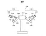
図1は、本発明の一実施形態の圧電駆動装置1300を備えた双腕ロボット1000の構造を示す模式正面図である。図1に示すように双腕ロボット1000は本体部1190を備えている。そして、本体部1190に接続して一対の腕部1200が設置されている。各腕部1200には、肩関節部1210、第1リンク部1220、肘関節部1230、第2リンク部1240、手首関節部1250、ロボットハンド1260が、本体部1190側からこの順に設置されている。第1リンク部1220の肘関節部1230側には、肘関節部1230を回動させて、第1リンク部1220に対して第2リンク部1240を回動させるための圧電駆動装置1300が設置されている。なお、他の関節部に対しても同様に、関節部を回動させるための圧電駆動装置が設置されているが、いずれの圧電駆動装置の動作も、基本的に、圧電駆動装置1300と同様であるので、以下では、代表して圧電駆動装置1300を例に説明する。A. Dual-arm robot of the embodiment:
FIG. 1 is a schematic front view showing the structure of a dual-
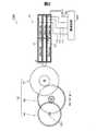
図2は、圧電駆動装置1300の一例を示す概略構成図である。圧電駆動装置1300は、ギヤトレイン50に含まれる被駆動体としてのローターR1を駆動する圧電駆動部10と、圧電駆動部10を駆動する駆動回路300と、を備えている。 FIG. 2 is a schematic configuration view showing an example of the
ギヤトレイン50は、圧電駆動部10によって駆動(回転)される被駆動体としての第1ローターR1と、第1ローターR1によって回転される第2ローターR2と、第2ローターR2によって回転される第3ローターR3と、を有している。このギヤトレイン50は、第1ローターR1と第3ローターR3のギヤ比(変速比)が1:M(M>1)の減速装置ある。以下、第1ローターR1に対する第3ローターのギヤ比Mを「減速比M」とも呼ぶ。第3ローターR3は、肘関節部1230(図1)の回転軸1231と同心で連結されている。従って、圧電駆動部10によって第1ローターR1が回転すると、これに応じて第3ローターR3が減速比Mで回転する。これにより、第3ローターR3の回転に応じて回転軸1231を介して肘関節部1230が回転(回動)し、肘関節部1230の回動に応じて第2リンク部1240が第1リンク部1220に対して回動する。 The
図3は、圧電駆動部10の概略構成図である。図3(A)は、圧電駆動部10の平面図であり、図3(B)はそのB−B断面図である。圧電駆動部10は、振動板200と、振動板200の両面(第1面211と第2面212)にそれぞれ配置された2つの圧電振動体100とを備える。圧電振動体100は、基板120と、基板120の上に形成された第1電極130と、第1電極130の上に形成された圧電体140と、圧電体140の上に形成された第2電極150と、を備えている。第1電極130と第2電極150は、圧電体140を挟持している。2つの圧電振動体100は、振動板200を中心として対称に配置されている。2つの圧電振動体100は同じ構成を有しているので、以下では特に断らない限り、振動板200の上側にある圧電振動体100の構成を説明する。 FIG. 3 is a schematic block diagram of the
圧電振動体100の基板120は、第1電極130と圧電体140と第2電極150を成膜プロセスで形成するための基板として使用される。また、基板120は機械的な振動を行う振動板としての機能も有する。基板120は、例えば、Si,Al2O3,ZrO2などで形成することができる。Si製の基板120として、例えば半導体製造用のSiウェハーを利用することが可能である。この実施形態において、基板120の平面形状は長方形である。基板120の厚みは、例えば10μm以上100μm以下の範囲とすることが好ましい。基板120の厚みを10μm以上とすれば、基板120上の成膜処理の際に基板120を比較的容易に取扱うことができる。また、基板120の厚みを100μm以下とすれば、薄膜で形成された圧電体140の伸縮に応じて、基板120を容易に振動させることができる。The
第1電極130は、基板120上に形成された1つの連続的な導電体層として形成されている。一方、第2電極150は、図2(A)に示すように、5つの導電体層150a〜150e(「第2電極150a〜150e」とも呼ぶ)に区分されている。中央にある第2電極150eは、基板120の幅方向の中央において、基板120の長手方向のほぼ全体に亘る長方形形状に形成されている。他の4つの第2電極150a,150b,150c,150dは、同一の平面形状を有しており、基板120の四隅の位置に形成されている。図2の例では、第1電極130と第2電極150は、いずれも長方形の平面形状を有している。第1電極130や第2電極150は、例えばスパッタリングによって形成される薄膜である。第1電極130や第2電極150の材料としては、例えばAl(アルミニウム)や、Ni(ニッケル)、Au(金)、Pt(白金)、Ir(イリジウム)などの導電性の高い任意の材料を利用可能である。なお、第1電極130を1つの連続的な導電体層とする代わりに、第2電極150a〜150eと実質的に同じ平面形状を有する5つの導電体層に区分してもよい。なお、第2電極150a〜150eの間の電気的接続のための配線(又は配線層及び絶縁層)と、第1電極130及び第2電極150a〜150eと駆動回路との間の電気的接続のための配線(又は配線層及び絶縁層)とは、図2では図示が省略されている。 The
圧電体140は、第2電極150a〜150eと実質的に同じ平面形状を有する5つの圧電体層として形成されている。この代わりに、圧電体140を、第1電極130と実質的に同じ平面形状を有する1つの連続的な圧電体層として形成してもよい。第1電極130と圧電体140と第2電極150a〜150eとの積層構造によって、5つの圧電素子110a〜110e(図2(A))が構成される。5つの圧電素子110a〜110eのうちの4つの圧電素子110a〜110dは、第1の対角にある一対の圧電素子110a,110dと、第2の対角にある一対の圧電素子110b,110cとに区分され、これらは、圧電振動体100の長手方向に沿った中央線CXに対して、左右対称の位置関係にある。残りの圧電素子110eは、一対の圧電素子110a,110dと他の一対の圧電素子110b,110cに挟まれて、中央線CXに沿って圧電振動体100の幅方向の中央位置にある。なお、以下では、一対の圧電素子110a,110dを「第1の圧電素子110a,110d」とも呼び、他の一対の圧電素子110b,110cを「第2の圧電素子110b,110c」とも呼ぶ。また、中央の圧電素子110eを「第3の圧電素子110e」とも呼ぶ。 The
圧電体140は、例えばゾル−ゲル法やスパッタリング法によって形成される薄膜である。圧電体140の材料としては、ABO3型のペロブスカイト構造を採るセラミックスなど、圧電効果を示す任意の材料を利用可能である。ABO3型のペロブスカイト構造を採るセラミックスとしては、例えばチタン酸ジルコン酸鉛(PZT)、チタン酸バリウム、チタン酸鉛、ニオブ酸カリウム、ニオブ酸リチウム、タンタル酸リチウム、タングステン酸ナトリウム、酸化亜鉛、チタン酸バリウムストロンチウム(BST)、タンタル酸ストロンチウムビスマス(SBT)、メタニオブ酸鉛、亜鉛ニオブ酸鉛、スカンジウムニオブ酸鉛等を用いることが可能である。またセラミック以外の圧電効果を示す材料、例えばポリフッ化ビニリデン、水晶等を用いることも可能である。圧電体140の厚みは、例えば50nm(0.05μm)以上20μm以下の範囲とすることが好ましい。この範囲の厚みを有する圧電体140の薄膜は、成膜プロセスを利用して容易に形成することができる。圧電体140の厚みを0.05μm以上とすれば、圧電体140の伸縮に応じて十分に大きな力を発生することができる。また、圧電体140の厚みを20μm以下とすれば、圧電振動体100(圧電駆動部10)を十分に小型化することができる。The
図4は、振動板200の平面図である。振動板200は、長方形形状の振動体部210と、振動体部210の左右の長辺からそれぞれ3本ずつ延びる接続部220とを有しており、また、左右の3本の接続部220にそれぞれ接続された2つの取付部230を有している。なお、図4では、図示の便宜上、振動体部210にハッチングを付している。取付部230は、ネジ240によって他の部材に圧電駆動部10を取り付けるために用いられる。振動板200は、例えば、シリコン、シリコン化合物、ステンレス鋼、アルミニウム、アルミニウム合金、チタン、チタン合金、銅、銅合金、鉄−ニッケル合金などの金属、金属酸化物、またはダイヤモンド等の材料で形成することが可能である。 FIG. 4 is a plan view of the
振動体部210の上面(第1面)及び下面(第2面)には、圧電振動体100(図3)がそれぞれ接着剤を用いて接着される。振動体部210の長さLと幅Wの比は、L:W=約7:2とすることが好ましい。この比は、振動体部210がその平面に沿って左右に屈曲する超音波振動(後述)を行うために好ましい値である。振動体部210の長さLは、例えば0.1mm以上30mm以下の範囲とすることができ、幅Wは、例えば0.05mm以上8mm以下の範囲とすることができる。なお、振動体部210が超音波振動を行うために、長さLは50mm以下とすることが好ましい。振動体部210の厚み(振動板200の厚み)は、例えば20μm以上700μm以下の範囲とすることができる。振動体部210の厚みを20μm以上とすれば、圧電振動体100を支持するために十分な剛性を有するものとなる。また、振動体部210の厚みを700μm以下とすれば、圧電振動体100の変形に応じて十分に大きな変形を発生することができる。 The piezoelectric vibrating body 100 (FIG. 3) is bonded to the upper surface (first surface) and the lower surface (second surface) of the vibrating
振動板200の一方の短辺には、突起部20(「接触部」や「当接部」、「作用部」とも呼ぶ)が設けられている。突起部20は、被駆動体と接触して、被駆動体に力を与えるための部材である。突起部20は、セラミックス(例えばSi,SiC,Al2O3,Zr02)などの耐久性がある材料で形成することが好ましい。A protrusion 20 (also referred to as a “contact portion”, a “contact portion”, or an “action portion”) is provided on one short side of the
図2に示すように、圧電駆動部10の5つの第2電極150a〜150eのうちで、対角にある一対の第2電極150a,150dが配線151を介して互いに電気的に接続され、他の対角の一対の第2電極150b,150cも配線152を介して互いに電気的に接続されている。これらの配線151,152は成膜処理によって形成しても良く、或いは、ワイヤ状の配線によって実現してもよい。図2の右側にある3つの第2電極150b,150e,150dと、第1電極130(図3)は、配線310,312,314,320を介して駆動回路300に電気的に接続されている。駆動回路300は、一対の第2電極150a,150dと第1電極130との間に周期的に変化する交流電圧又は脈流電圧を印加することにより、圧電駆動部10を超音波振動させて、突起部20に接触するローター(被駆動体)を所定の回転方向に回転させることが可能である。ここで、「脈流電圧」とは、交流電圧にDCオフセットを付加した電圧を意味し、その電圧(電界)の向きは、一方の電極から他方の電極に向かう一方向である。また、他の一対の第2電極150b,150cと第1電極130との間に交流電圧又は脈流電圧を印加することにより、突起部20に接触するローターを逆方向に回転させることが可能である。このような電圧の印加は、振動板200の両面に設けられた2つの圧電振動体100に対して同時に行われる。なお、図2に示した配線151,152,310,312,314,320を構成する配線(又は配線層及び絶縁層)は、図3では図示が省略されている。 As shown in FIG. 2, among the five
図5は、圧電駆動部10の動作の例を示す説明図である。圧電駆動部10の突起部20は、被駆動体としての第1ローターR1の外周に接触している。図5に示す例では、駆動回路300(図2)は、一対の第2電極150a,150dと第1電極130との間に交流電圧又は脈流電圧を印加しており、第1の圧電素子110a,110dは図4の矢印xの方向に伸縮する。これに応じて、圧電駆動部10の振動体部210が圧電振動体部210の平面内で屈曲して蛇行形状(S字形状)に変形し、突起部20の先端が矢印yの向きに往復運動するか、又は、楕円運動する。その結果、第1ローターR1は、その中心51の周りに所定の方向z(図5では時計回り方向)に回転する。図3で説明した振動板200の3つの接続部220は、このような振動体部210の振動の節(ふし)の位置に設けられている。なお、駆動回路300が、他の一対の第2電極150b,150cと第1電極130との間に交流電圧又は脈流電圧を印加する場合には、第1ローターR1は逆方向に回転する。なお、中央の第2電極150eに、一対の第2電極150a,150d(又は他の一対の第2電極150b,150c)と同じ電圧を印加すれば、圧電駆動部10の運動には、中央の第3の圧電素子110eが長手方向に伸縮する成分が加わるので、突起部20から第1ローターR1に与える力をより大きくすることが可能である。なお、圧電駆動部10(又は圧電振動体100)のこのような動作については、上記先行技術文献1(特開2004−320979号公報、又は、対応する米国特許第7224102号)に記載されており、その開示内容は参照により組み込まれる。 FIG. 5 is an explanatory view showing an example of the operation of the
図6は、圧電駆動部10に許容する出力トルクについて示す説明図である。圧電駆動部10が出力可能なトルク(可能出力トルク)の範囲は、0〜出力し得る最大のトルク(以下、「可能最大出力トルク」とも呼ぶ)Tmaxの範囲であり、基本的には、圧電駆動部10は可能出力トルクの範囲内の出力トルクTdで作動させることができる。 FIG. 6 is an explanatory view showing output torque allowed to the
ここで、駆動回路300による圧電駆動部10の駆動を停止した場合、圧電駆動部10は突起部20が被駆動体としての第1ローターR1の外周に接触して押圧した状態でその作動を停止する(図2,5)。この際、突起部20の第1ローターR1との接触面には、第1ローターR1を静止状態で保持するための保持力Fs及び保持トルクTsが発生する。
Fs=μs×Ns ・・・(2)
Ts=Fs×r1=[μs×Ns]×r1 ・・・(3)
ここで、Nsは圧電駆動部10の作動停止時に突起部20が第1ローターR1を押圧する押圧力(以下、「作動停止時押圧力」とも呼ぶ)、μsは突起部20と第1ローターR1との間の静止摩擦係数、r1は第1ローターR1の半径(以下、「ローター半径」とも呼ぶ)である。Here, when the drive of the
Fs = μs × Ns (2)
Ts = Fs × r1 = [μs × Ns] × r1 (3)
Here, Ns is a pressing force at which the
この保持トルクTsは、上式(3)に示すように、圧電駆動部10が出力し得る最大のトルク(可能最大出力トルク)Tmax以下の範囲で、静止摩擦係数μs及び作動停止時押圧力Nsに応じて変化する。例えば、静止摩擦係数μsは第1ローターR1及び突起部20の部材に応じて変化するものであり、静止摩擦係数μsが低い場合には、これに応じて保持トルクTsは低くなる。また、作動停止時押圧力Nsは、第1ローターR1と圧電駆動部10の設置状態に応じて変化するものであり、作動停止時押圧力Nsが低くなると、これに応じて保持トルクTsは低くなる。このため、肘関節部1230から第3ローターR3及び第2ローターR2を介して第1ローターR1に掛かる負荷トルクTrがこの保持トルクTs以上であった場合、第1ローターR1、すなわち、肘関節部1230をそのままの姿勢で静止状態に保持することができなくなる。逆に言えば、第1ローターに掛かる負荷トルクTrは、この保持トルクTs未満に制限されることが好ましい。言い換えると、肘関節部1230の第2リンク部1240側に掛かる負荷による負荷トルクは、保持トルクTsに減速比Mを乗じた値Ts・M未満に制限されることが好ましい。ここで、「減速比M」とは、圧電駆動部10の被駆動体としてのローターに対する被駆動体を介して駆動される負荷部の回転軸と同心で連結されたローターのギヤ比である(図2参照)。なお、本例では、被駆動体としてのローターは第1ローターR1、負荷部はロボットハンド1260、手首関節部1250、及び、第2リンク部1240が接続された肘関節部1230)、負荷部の回転軸は回転軸1231である。 The holding torque Ts is, as shown in the above equation (3), the static friction coefficient μs and the pressing force Ns at the time of non-operation within the range of the maximum torque (possible maximum output torque) Tmax which the
ところで、一般に、静止摩擦係数μs>動摩擦係数μkとなる。そこで、圧電駆動部10の出力トルクTdとして許容する最大出力トルク(許容最大出力トルク)Tlimを、次式で与えることが好ましい。
Tlim=[μk×Ns]×r1 ・・・(4)
ここで、μkは動摩擦係数、Nsは作動停止時押圧力、r1は第1ローター半径r1である。Generally, the static friction coefficient μs> the dynamic friction coefficient μk. Therefore, it is preferable to give the maximum output torque (permissible maximum output torque) Tlim to be accepted as the output torque Td of the
Tlim = [μk × Ns] × r1 (4)
Here, μk is a dynamic friction coefficient, Ns is a pressing force at the time of non-operation, and r1 is a first rotor radius r1.
設定した出力トルクTd以上の負荷トルクの負荷を駆動することはできないので、第1ローターR1に掛かる負荷に対応する負荷トルクTrは、出力トルクTd以下である。また、設定される出力トルクTdの最大値は許容最大出力トルクTlimであり、動摩擦係数μk<静止摩擦係数μsの関係から、許容最大出力トルクTlim<保持トルクTsとなるので、設定した出力トルクTdにより駆動できる負荷トルクTrは、必ず、保持トルクTsよりも低くすることができる。これにより、保持トルクTs以上の出力トルクTdで負荷トルクTrを駆動しないように制限することができる。この結果、圧電駆動部10によって肘関節部1230を駆動している状態から、圧電駆動部10の作動を停止して、第1ローターR1の回転すなわち肘関節部1230の回動を停止した場合に、第1ローターR1の回転の位置すなわち肘関節部1230の回動の位置を、停止した瞬間に逆方向に動いてしまうことなく、所望の位置で停止させることができる。そして、突起部20と第1ローターR1との間で滑りが発生することなく、保持トルクTsによってその停止した位置での静止状態を保持することが可能である。 Since it is not possible to drive a load having a load torque equal to or higher than the set output torque Td, the load torque Tr corresponding to the load applied to the first rotor R1 is equal to or less than the output torque Td. Further, the maximum value of the output torque Td to be set is the allowable maximum output torque Tlim, and from the relationship of the dynamic friction coefficient μk <static friction coefficient μs, the allowable maximum output torque Tlim <holding torque Ts, so the set output torque Td The load torque Tr that can be driven by the drive torque can always be lower than the holding torque Ts. Thus, the load torque Tr can be limited so as not to be driven by the output torque Td which is equal to or higher than the holding torque Ts. As a result, from the state where the elbow joint 1230 is driven by the
なお、出力トルクTdの設定は、あらかじめ、例えば、装置の出荷調整時において、以下のように実行される。肘関節部1230の圧電駆動装置1300においては、図1に示した第2リンク部1240に貼り付けたトルクセンサーTsで肘関節部1230に掛かる負荷トルクを測定する。但し、把持可能とする最大の負荷をロボットハンド1260で把持した状態で測定する。そして、測定した負荷トルクを1/M(Mは減速比)倍した値を第1ローターR1に掛かる最大の負荷トルクTrとして求めることにより、求めた負荷トルクTrに対応する出力トルクTdを上記した許容出力トルクの範囲内で設定すればよい。仮に負荷トルクTrが、許容最大出力トルクTlimより大きい場合には、圧電駆動部10の突起部20と第1ローターR1との接触状態を調整することにより、作動停止時押圧力Nsを大きくすることにより、負荷トルクTrが許容最大出力トルクTlim以下となるように調整すればよい。 The setting of the output torque Td is performed in advance as follows, for example, at the time of shipping adjustment of the device. In the
以上の説明では、圧電駆動部10の出力トルクTdを、0以上で許容最大出力トルクTlim以下の許容出力トルクの範囲内に設定することとし、許容最大出力トルクTlimとして上記式(4)を用いた。これに対して、許容最大出力トルクTlimとして、下式(5)で表すものとしてもよい。
Tlim=[μk×Ns]×r1×fs ・・・(5)
ここで、fsは1以下の係数であり、安全率を示している。fs=1の場合は(5)式は(4)式と同じである。係数fsが小さいほど、許容最大出力トルクTlimは小さくなるので、設定された出力トルクTdに対応する負荷トルクTrも小さくなり、より確実に、圧電駆動部10によって肘関節部1230を駆動している状態から、圧電駆動部10の作動を停止した場合に、所望の位置で停止させるとともに、その停止した位置での静止状態を保持することが可能である。但し、安全率fsが小さいほど駆動できる負荷が小さくなる。なお、fsとしては、7/10〜9/10の範囲に設定されるのが好ましい。例えば、8/10(=4/5)に設定されることがより好ましい。In the above description, the output torque Td of the
Tlim = [μk × Ns] × r1 × fs (5)
Here, fs is a coefficient of 1 or less and indicates a safety factor. When fs = 1, equation (5) is the same as equation (4). Since the allowable maximum output torque Tlim decreases as the coefficient fs decreases, the load torque Tr corresponding to the set output torque Td also decreases, and the
なお、以上の説明では、肘関節部1230における圧電駆動装置1300の圧電駆動部10の動作条件を例に説明したが、他の関節部等に用いられた圧電駆動装置の圧電駆動部においても同様にして動作条件を設定することができる。また、以上の説明では、圧電駆動部10の突起部20を第1ローターR1の外周に接触させる構成であるので、式(4)で表した保持トルクTsや、式(5),(6)で表した許容最大出力トルクTlimでは、第1ローター半径r1が用いられている。但し、突起部20を第1ローターR1の円周面に接触させる場合には、第1ローターR1の中心51から突起部20の接触位置までの距離がr1となる。 In the above description, the operating conditions of the
B.圧電駆動部の他の実施形態:
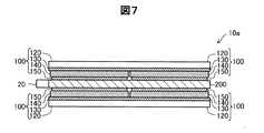
図7は、本発明の他の実施形態としての圧電駆動部10aの断面図であり、上記実施形態の図3(B)に対応する図である。この圧電駆動部10aでは、圧電振動体100が、図3(B)とは上下を逆にした状態で振動板200に配置されている。すなわち、ここでは、第2電極150が振動板200に近く、基板120が振動板200から最も遠くなるように配置されている。なお、図7においても、図3(B)と同様に、第2電極150a〜150eの間の電気的接続のための配線(又は配線層及び絶縁層)と、第1電極130及び第2電極150a〜150eと駆動回路との間の電気的接続のための配線(又は配線層及び絶縁層)とは、図示が省略されている。この圧電駆動部10aも、第1実施形態と同様な効果を達成することができる。B. Other Embodiments of Piezoelectric Drive:
FIG. 7 is a cross-sectional view of a
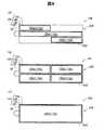
図8(A)は、本発明の更に他の実施形態としての圧電駆動部10bの平面図であり、上記実施形態の図3(A)に対応する図である。図8(A)〜(C)では、図示の便宜上、振動板200の接続部220や取付部230は図示が省略されている。図8(A)の圧電駆動部10bでは、一対の第2電極150b,150cが省略されている。この圧電駆動部10bも、図5に示すような1つの方向zにローターR1を回転させることが可能である。なお、図8(A)の3つの第2電極150a,150e,150dには同じ電圧が印加されるので、これらの3つの第2電極150a,150e,150dを、連続する1つの電極層として形成してもよい。 FIG. 8A is a plan view of a
図8(B)は、本発明の更に他の実施形態としての圧電駆動部10cの平面図である。この圧電駆動部10cでは、図3(A)の中央の第2電極150eが省略されており、他の4つの第2電極150a,150b,150c,150dが図3(A)よりも大きな面積に形成されている。この圧電駆動部10cも、第1実施形態とほぼ同様な効果を達成することができる。 FIG. 8B is a plan view of a
図8(C)は、本発明の更に他の実施形態としての圧電駆動部10dの平面図である。この圧電駆動部10dでは、図3(A)の4つの第2電極150a,150b,150c,150dが省略されており、1つの第2電極150eが大きな面積で形成されている。この圧電駆動部10dは、長手方向に伸縮するだけであるが、突起部20から被駆動体(図示省略)に対して大きな力を与えることが可能である。 FIG. 8C is a plan view of a
図3及び図8(A)〜(C)から理解できるように、圧電振動体100の第2電極150としては、少なくとも1つの電極層を設けることができる。但し、図3及び図8(A),(B)に示す実施形態のように、長方形の圧電振動体100の対角の位置に第2電極150を設けるようにすれば、圧電振動体100及び振動板200を、その平面内で屈曲する蛇行形状に変形させることが可能である点で好ましい。 As can be understood from FIGS. 3 and 8A to 8C, at least one electrode layer can be provided as the
C.圧電駆動装置を用いた装置の他の実施形態:
上述した圧電駆動装置は、共振を利用することで被駆動体に対して大きな力を与えることができるものであり、各種の装置に適用可能である。圧電駆動装置は、例えば、ロボット、電子部品搬送装置(ICハンドラー)、投薬用ポンプ、時計のカレンダー送り装置、印刷装置(例えば紙送り機構。ただし、ヘッドに利用される圧電駆動装置では、振動板を共振させないので、ヘッドには適用不可である。)等の各種の機器における駆動装置として用いることが出来る。以下、図1に示した双腕ロボット以外の代表的な他の実施の形態について説明する。C. Other Embodiments of Device Using Piezoelectric Drive Device:
The above-described piezoelectric drive device can apply a large force to a driven body by utilizing resonance, and can be applied to various devices. The piezoelectric drive device is, for example, a robot, an electronic component transfer device (IC handler), a dosing pump, a calendar feeding device for a watch, a printing device (for example, a paper feeding mechanism. However, in a piezoelectric drive device used for a head, a diaphragm Can not be applied to the head, and can be used as a driving device in various devices such as the head. Hereinafter, another typical embodiment other than the double-arm robot shown in FIG. 1 will be described.
図9は、上述の圧電駆動装置1300を利用した単腕ロボット2050の一例を示す説明図である。単腕ロボット2050は、複数本のリンク部2012(「リンク部材」とも呼ぶ)と、それらリンク部2012の間を回動又は屈曲可能な状態で接続する複数の関節部2020とを備えたアーム2010(「腕部」とも呼ぶ)を有している。それぞれの関節部2020には、上述した圧電駆動装置1300のうちの圧電駆動部10が内蔵されており、圧電駆動部10を用いて関節部2020を任意の角度だけ回動又は屈曲させることが可能である。アーム2010の先端には、ロボットハンド2000が接続されている。ロボットハンド2000は、一対の把持部2003を備えている。ロボットハンド2000にも圧電駆動部10が内蔵されており、圧電駆動部10を用いて把持部2003を開閉して物を把持することが可能である。また、ロボットハンド2000とアーム2010との間にも圧電駆動部10が設けられており、圧電駆動部10を用いてロボットハンド2000をアーム2010に対して回転させることも可能である。なお、各圧電駆動部10を制御する駆動回路300は不図示の制御回路に含まれている。 FIG. 9 is an explanatory view showing an example of a single-
図10は、図9に示した単腕ロボット2050の手首部分の説明図である。手首の関節部2020は、手首回動部2022を挟持しており、手首回動部2022に手首のリンク部2012が、手首回動部2022の中心軸O周りに回動可能に取り付けられている。手首回動部2022は、圧電駆動部10を備えており、圧電駆動部10は、手首のリンク部2012及びロボットハンド2000を中心軸O周りに回動させる。なお、手首回動部2022も、複数の関節部2020の一つとみることができ、この場合手首の関節部2020はリンク部2012の一つとみつことができる。ロボットハンド2000には、複数の把持部2003が立設されている。把持部2003の基端部はロボットハンド2000内で移動可能となっており、この把持部2003の根元の部分に圧電駆動部10が搭載されている。このため、圧電駆動部10を動作させることで、把持部2003を移動させて対象物を把持することができる。 FIG. 10 is an explanatory view of a wrist portion of the single-
なお、ロボットとしては、実施形態の双腕ロボット(図1)や他の実施形態の単腕ロボットに限らず、腕の数が3以上の多腕ロボットにも圧電駆動部10を適用可能である。ここで、手首の関節部2020やロボットハンド2000の内部には、圧電駆動部10の他に、力覚センサーやジャイロセンサー等の各種装置に電力を供給する電力線や、信号を伝達する信号線等が含まれ、非常に多くの配線が必要になる。従って、関節部2020やロボットハンド2000の内部に配線を配置することは非常に困難だった。しかしながら、上述した実施形態の圧電駆動部10は、通常の電動モーターや、従来の圧電駆動装置よりも駆動電流を小さくできるので、関節部2020(特に、アーム2010の先端の関節部)やロボットハンド2000のような小さな空間でも配線を配置することが可能になる。 As the robot, the
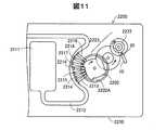
図11は、上述の圧電駆動装置1300を利用した送液ポンプ2200の一例を示す説明図である。送液ポンプ2200は、ケース2230内に、リザーバー2211と、チューブ2212と、圧電駆動部10と、ローター2222と、減速伝達機構2223と、カム2202と、複数のフィンガー2213、2214、2215、2216、2217、2218、2219と、が設けられている。なお、駆動回路300は不図示である。リザーバー2211は、輸送対象である液体を収容するための収容部である。チューブ2212は、リザーバー2211から送り出される液体を輸送するための管である。圧電駆動部10の突起部20は、ローター2222の側面に押し付けた状態で設けられており、圧電駆動部10がローター2222を回転駆動する。ローター2222の回転力は減速伝達機構2223を介してカム2202に伝達される。フィンガー2213から2219はチューブ2212を閉塞させるための部材である。カム2202が回転すると、カム2202の突起部2202Aによってフィンガー2213から2219が順番に放射方向外側に押される。フィンガー2213から2219は、輸送方向上流側(リザーバー2211側)から順にチューブ2212を閉塞する。これにより、チューブ2212内の液体が順に下流側に輸送される。こうすれば、極く僅かな量を精度良く送液可能で、しかも小型な送液ポンプ2200を実現することができる。なお、各部材の配置は図示されたものには限られない。また、フィンガーなどの部材を備えず、ローター2222に設けられたボールなどがチューブ2212を閉塞する構成であってもよい。上記のような送液ポンプ2200は、インシュリンなどの薬液を人体に投与する投薬装置などに活用できる。ここで、上述した実施形態の圧電駆動装置1300を用いることにより、従来の圧電駆動装置よりも駆動電流が小さくなるので、投薬装置の消費電力を抑制することができる。従って、投薬装置を電池駆動する場合は、特に有効である。 FIG. 11 is an explanatory view showing an example of a
D.変形例:
なお、この発明は上記の実施例や実施形態に限られるものではなく、その要旨を逸脱しない範囲において種々の態様において実施することが可能であり、例えば次のような変形も可能である。D. Modification:
The present invention is not limited to the above embodiments and embodiments, and can be implemented in various modes without departing from the scope of the invention. For example, the following modifications can be made.
(1)上記実施形態では、基板120の上に第1電極130と圧電体140と第2電極150とが形成されていたが、基板120を省略して、振動板200の上に第1電極130と圧電体140と第2電極150とを形成するようにしてもよい。(1) In the above embodiment, although the
(2)上記実施形態では、振動板200の両面にそれぞれ1つの圧電振動体100を設けていたが、圧電振動体100の一方を省略することも可能である。但し、振動板200の両面にそれぞれ圧電振動体100を設けるようにすれば、振動板200をその平面内で屈曲した蛇行形状に変形させることがより容易である点で好ましい。(2) In the above embodiment, one
(3)上記各実施形態では、圧電素子として、成膜プロセスにより形成した圧電体を用いるものを例に取り説明したが、圧電体は、バルクの圧電体であってもよい。(3) In the above embodiments, as the piezoelectric element, one using a piezoelectric body formed by a film forming process has been described as an example, but the piezoelectric body may be a bulk piezoelectric body.
(4)上記実施形態では、振動体部210の左右の長辺からそれぞれ3本ずつ延びる接続部220によって振動体部210を振動可能に支持する構成を例に説明したが、接続部220の配置位置や数は、これに限定されるものではなく、種々の配置位置や数を採用することができる。例えば、長手方向に沿った片側のみに接続部を設けて、振動体部210を片持ち状態で支持する構造としても良い。また、振動体部210の突起部20とは反対側の短辺に接続部を設けて、振動体部210を片持ち状態で支持する構造としても良い。(4) In the above embodiment, the configuration in which the vibrating
本発明は、上述の実施形態や実施例、変形例に限られるものではなく、その趣旨を逸脱しない範囲において種々の構成で実現することができる。例えば、発明の概要の欄に記載した各形態中の技術的特徴に対応する実施形態、実施例、変形例中の技術的特徴は、上述の課題の一部または全部を解決するために、或いは、上述の効果の一部または全部を達成するために、適宜、差し替えや組み合わせを行うことが可能である。また、その技術的特徴が本明細書中に必須なものとして説明されていなければ、適宜、削除することが可能である。 The present invention is not limited to the above-described embodiments, examples, and modifications, and can be implemented with various configurations without departing from the scope of the invention. For example, the technical features in the embodiments, examples, and modifications corresponding to the technical features in the respective forms described in the section of the summary of the invention are for solving some or all of the problems described above, or In order to achieve part or all of the above-described effects, replacements or combinations can be made as appropriate. Also, if the technical features are not described as essential in the present specification, they can be deleted as appropriate.
10,10a,10b,10c,10d…圧電駆動部
20…突起部(接触部、作用部)
50…ギヤトレイン
51…中心51
100…圧電振動体
110a,110b,110c,110d,110e…圧電素子
120…基板
125…絶縁層
130…第1電極
140…圧電体
150,150a,150b,150c,150d,150e…第2電極
151,152…配線
200…振動板
210…振動体部
220…接続部
230…取付部
240…ネジ
300…駆動回路
310,312,314,320…配線
1000…双腕ロボット
1190…本体部
1200…腕部
1210…肩関節部
1220…第1リンク部
1230…肘関節部
1231…回転軸
1240…第2リンク部
1250…手首関節部
1260…ロボットハンド
1300…圧電駆動装置
2000…ロボットハンド
2003…把持部
2010…アーム
2012…リンク部
2020…関節部
2022…手首回動部
2050…ロボット
2200…送液ポンプ
2202…カム
2202A…突起部
2211…リザーバー
2212…チューブ
2213…フィンガー
2222…ローター
2223…減速伝達機構
2230…ケース
R1…第1ローター
R2…第2ローター
R3…第3ローター10, 10a, 10b, 10c, 10d · · ·
50: gear train 51:
DESCRIPTION OF
Claims (6)
Translated fromJapanese前記圧電駆動部を駆動する駆動回路と、
を備え、
前記駆動回路は、許容最大出力トルクTlim以下を許容出力トルクの範囲とし、前記圧電駆動部の出力トルクを前記許容出力トルクの範囲内に設定して前記圧電駆動部を作動させ、
前記許容最大出力トルクTlimは、前記被駆動体の回転中心と前記接触部の接触位置との距離r1、前記被駆動体と前記接触部との動摩擦係数μk、前記圧電駆動部の作動を停止した際に前記接触部が前記被駆動体を押圧する押圧力Ns、1以下の係数fs、を用いて、下式(1)で表され、前記出力トルクが前記許容最大出力トルクTlim以下となるように、前記押圧力Nsを調整することによって設定される
ことを特徴とする圧電駆動装置。
Tlim=r1×μk×Ns×fs ・・・(1)A piezoelectric drive unit having a contact portion capable of coming into contact with a driven body and having a piezoelectric body;
A drive circuit for driving the piezoelectric drive unit;
Equipped with
The drive circuit operates the piezoelectric drive unit by setting the output torque of the piezoelectric drive unit within the range of the allowable output torque with the allowable maximum output torque Tlim or less as the allowable output torque range.
The allowable maximum output torque Tlim isthe distance r1 between the rotation center of the driven body and the contact position of the contact portion, the dynamic friction coefficient μk between the driven body and the contact portion, and the operation of the piezoelectric drive portion stopped. The contact portion is expressed by the following equation (1)using a pressing force Ns for pressing the driven body, a coefficient fs of 1 orless, and the output torque becomes equal to or less than the allowable maximum output torque Tlim. The piezoelectric drive deviceis set by adjusting the pressing force Ns .
Tlim = r1 × μk × Ns × fs (1)
前記係数fsは1未満の値である、圧電駆動装置。The piezoelectric drive device according to claim 1, wherein
Piezoelectric drive, wherein the factor fs is less than one.
前記被駆動体に加わる負荷トルクは、前記許容最大出力トルクTlim以下に設定された出力トルク以下に制限される、圧電駆動装置。The piezoelectric drive device according to claim 1 or 2, wherein
The piezoelectric drive device, wherein a load torque applied to the driven body is limited to an output torque or less set to the allowable maximum output torque Tlim or less.
前記複数のリンク部を接続する関節部と、
前記複数のリンク部を前記関節部で回動させる請求項1から請求項3までのいずれか一項に記載の少なくとも一つの圧電駆動装置と、
を備えるロボット。A plurality of link portions and a joint portion connecting the plurality of link portions;
The at least one piezoelectric drive device according to any one of claims 1 to 3, wherein the plurality of link portions are rotated by the joint portion.
Robot with
前記圧電駆動装置の少なくとも一つを駆動することで前記複数のリンク部を前記関節部で回動させ、
前記圧電駆動装置の駆動回路は、許容最大出力トルクTlim以下を許容出力トルクの範囲とし、前記圧電駆動部の出力トルクTdを前記許容出力トルクの範囲内に設定して前記圧電駆動部を作動させ、
前記許容最大出力トルクTlimは、前記被駆動体の回転中心と前記接触部の接触位置との距離r1、前記被駆動体と前記接触部との動摩擦係数μk、前記圧電駆動部の作動を停止した際に前記接触部が前記被駆動体を押圧する押圧力Ns、1以下の係数fs、を用いて、下式(1)で表され、前記出力トルクが前記許容最大出力トルクTlim以下となるように、前記押圧力Nsを調整することによって設定される
ことを特徴とするロボットの駆動方法。
Tlim=r1×μk×Ns×fs ・・・(1)5. The method of driving a robot according to claim 4, wherein the plurality of link portions are rotated by the joint portion by driving at least one of the piezoelectric drive devices.
The drive circuit of the piezoelectric drive device operates the piezoelectric drive portion by setting the output torque Td of the piezoelectric drive portion within the range of the allowable output torque with the allowable maximum output torque Tlim or less as the allowable output torque range. ,
The allowable maximum output torque Tlim isthe distance r1 between the rotation center of the driven body and the contact position of the contact portion, the dynamic friction coefficient μk between the driven body and the contact portion, and the operation of the piezoelectric drive portion stopped. The contact portion is expressed by the following equation (1)using a pressing force Ns for pressing the driven body, a coefficient fs of 1 orless, and the output torque becomes equal to or less than the allowable maximum output torque Tlim. The method of driving the robotis set by adjusting the pressing force Ns .
Tlim = r1 × μk × Ns × fs (1)
前記圧電駆動装置の駆動回路は、許容最大出力トルクTlim以下を許容出力トルクの範囲とし、前記圧電駆動部の出力トルクTdを前記許容出力トルクの範囲内に設定して前記圧電駆動部を作動させ、
前記許容最大出力トルクTlimは、前記被駆動体の回転中心と前記接触部の接触位置との距離r1、前記被駆動体と前記接触部との動摩擦係数μk、前記圧電駆動部の作動を停止した際に前記接触部が前記被駆動体を押圧する押圧力Ns、1以下の係数fs、を用いて、下式(1)で表され、前記出力トルクが前記許容最大出力トルクTlim以下となるように、前記押圧力Nsを調整することによって設定される
ことを特徴とする圧電駆動装置の駆動方法。A method of driving a piezoelectric drive device according to any one of claims 1 to 3, wherein
The drive circuit of the piezoelectric drive device operates the piezoelectric drive portion by setting the output torque Td of the piezoelectric drive portion within the range of the allowable output torque with the allowable maximum output torque Tlim or less as the allowable output torque range. ,
The allowable maximum output torque Tlim isthe distance r1 between the rotation center of the driven body and the contact position of the contact portion, the dynamic friction coefficient μk between the driven body and the contact portion, and the operation of the piezoelectric drive portion stopped. The contact portion is expressed by the following equation (1)using a pressing force Ns for pressing the driven body, a coefficient fs of 1 orless, and the output torque becomes equal to or less than the allowable maximum output torque Tlim. The method of driving apiezoelectric drive deviceis set by adjusting the pressing force Ns .
Priority Applications (2)
| Application Number | Priority Date | Filing Date | Title |
|---|---|---|---|
| JP2015062226AJP6511900B2 (en) | 2015-03-25 | 2015-03-25 | Piezoelectric drive device and drive method therefor, robot and drive method therefor |
| US15/043,676US9827672B2 (en) | 2015-03-25 | 2016-02-15 | Piezoelectric drive device, driving method thereof, robot, and driving method thereof |
Applications Claiming Priority (1)
| Application Number | Priority Date | Filing Date | Title |
|---|---|---|---|
| JP2015062226AJP6511900B2 (en) | 2015-03-25 | 2015-03-25 | Piezoelectric drive device and drive method therefor, robot and drive method therefor |
Related Child Applications (1)
| Application Number | Title | Priority Date | Filing Date |
|---|---|---|---|
| JP2019075270ADivisionJP6702482B2 (en) | 2019-04-11 | 2019-04-11 | Piezoelectric driving device and driving method thereof, robot and driving method thereof |
Publications (2)
| Publication Number | Publication Date |
|---|---|
| JP2016182016A JP2016182016A (en) | 2016-10-13 |
| JP6511900B2true JP6511900B2 (en) | 2019-05-15 |
Family
ID=56976509
Family Applications (1)
| Application Number | Title | Priority Date | Filing Date |
|---|---|---|---|
| JP2015062226AActiveJP6511900B2 (en) | 2015-03-25 | 2015-03-25 | Piezoelectric drive device and drive method therefor, robot and drive method therefor |
Country Status (2)
| Country | Link |
|---|---|
| US (1) | US9827672B2 (en) |
| JP (1) | JP6511900B2 (en) |
Families Citing this family (11)
| Publication number | Priority date | Publication date | Assignee | Title |
|---|---|---|---|---|
| WO2011127410A2 (en)* | 2010-04-09 | 2011-10-13 | Deka Products Limited Partnership | System and apparatus for robotic device and methods of using thereof |
| JP6467809B2 (en)* | 2014-08-13 | 2019-02-13 | セイコーエプソン株式会社 | Piezoelectric driving device and driving method thereof, robot and driving method thereof |
| CN106862841B (en)* | 2017-04-11 | 2018-08-03 | 山东昌隆机械制造股份有限公司 | A kind of transfer clamping device in workpiece welding process |
| JP2019067861A (en)* | 2017-09-29 | 2019-04-25 | セイコーエプソン株式会社 | Piezoelectric actuator, piezoelectric drive device, robot, electronic component transfer device and printer |
| CN107856057B (en)* | 2017-11-30 | 2024-03-29 | 深圳市优必选科技有限公司 | Link mechanism and robot |
| JP7080649B2 (en)* | 2018-01-17 | 2022-06-06 | キヤノン株式会社 | Control method, manufacturing method of goods, control program, recording medium, robot system, control device |
| JP7069815B2 (en)* | 2018-02-22 | 2022-05-18 | セイコーエプソン株式会社 | How to drive piezoelectric drive devices, robot hands, robots, electronic component transfer devices, printers, projectors and piezoelectric drive devices |
| JP7151166B2 (en)* | 2018-05-18 | 2022-10-12 | セイコーエプソン株式会社 | Grasping device and robot |
| US11020840B2 (en)* | 2018-12-11 | 2021-06-01 | The Boeing Company | Gripping system with clamp device and method of using the same |
| CN112123341B (en)* | 2020-11-24 | 2021-03-02 | 季华实验室 | Robot double arm coordinated motion control method, device and electronic device |
| IL285260B2 (en)* | 2021-08-01 | 2023-10-01 | Arugga A I Farming Ltd | Treatment system for growing plants |
Family Cites Families (14)
| Publication number | Priority date | Publication date | Assignee | Title |
|---|---|---|---|---|
| JPS6389071A (en)* | 1986-09-30 | 1988-04-20 | Hitachi Maxell Ltd | Ultrasonic motor with rated torque equal to half of maximum load torque |
| JPS63124782A (en)* | 1986-11-14 | 1988-05-28 | Hitachi Maxell Ltd | Ultrasonic motor having homeostasis characteristic |
| JPS63124781A (en)* | 1986-11-14 | 1988-05-28 | Hitachi Maxell Ltd | Homeostatic ultrasonic motor |
| JP2543055B2 (en)* | 1986-11-26 | 1996-10-16 | キヤノン株式会社 | Vibration wave drive |
| JPH1094276A (en)* | 1996-09-18 | 1998-04-10 | Nikon Corp | Vibration actuator |
| JP3987199B2 (en)* | 1998-03-31 | 2007-10-03 | マツダ株式会社 | Simulation device, simulation method, and storage medium |
| US6690101B2 (en)* | 2000-03-23 | 2004-02-10 | Elliptec Resonant Actuator Ag | Vibratory motors and methods of making and using same |
| JP2004320979A (en) | 2003-04-03 | 2004-11-11 | Seiko Epson Corp | Operating equipment and electrical equipment |
| KR101044130B1 (en)* | 2010-01-04 | 2011-06-24 | 삼성전기주식회사 | Piezoelectric Actuator Module |
| EP2422935B1 (en)* | 2010-08-31 | 2015-02-25 | Kabushiki Kaisha Yaskawa Denki | Robot, robot system, robot control device, and state determining method |
| JP5799596B2 (en)* | 2011-06-10 | 2015-10-28 | セイコーエプソン株式会社 | Piezoelectric actuator, robot hand, and robot |
| JP6292737B2 (en) | 2011-07-28 | 2018-03-14 | キヤノン株式会社 | Control method of vibration type driving device |
| JP5982774B2 (en)* | 2011-10-11 | 2016-08-31 | セイコーエプソン株式会社 | Motor controller, robot hand |
| JP2013236470A (en)* | 2012-05-09 | 2013-11-21 | Seiko Epson Corp | Piezoelectric motor, robot hand, robot, electronic component transfer device, electronic component inspection device, liquid sending pump, printing device, electronic clock, projection device, and transfer device |
- 2015
- 2015-03-25JPJP2015062226Apatent/JP6511900B2/enactiveActive
- 2016
- 2016-02-15USUS15/043,676patent/US9827672B2/enactiveActive
Also Published As
| Publication number | Publication date |
|---|---|
| US20160284968A1 (en) | 2016-09-29 |
| JP2016182016A (en) | 2016-10-13 |
| US9827672B2 (en) | 2017-11-28 |
Similar Documents
| Publication | Publication Date | Title |
|---|---|---|
| JP6511900B2 (en) | Piezoelectric drive device and drive method therefor, robot and drive method therefor | |
| JP6405785B2 (en) | Piezoelectric drive device, robot, and drive method thereof | |
| JP6398454B2 (en) | Piezoelectric drive device, robot, and drive method thereof | |
| JP6543951B2 (en) | Piezoelectric drive device, robot, and method of driving them | |
| CN106329985A (en) | Piezoelectric drive device, robot, and driving method for piezoelectric drive device | |
| JP6439466B2 (en) | Piezoelectric driving device, robot, and robot driving method | |
| US10147866B2 (en) | Piezoelectric driving device and driving method therefor, and robot and driving method therefor | |
| JP6601174B2 (en) | Piezoelectric actuators, stacked actuators, piezoelectric motors, robots, hands and liquid pumps | |
| JP6442913B2 (en) | Piezoelectric drive device, robot, and drive method thereof | |
| JP6503940B2 (en) | Piezoelectric drive device, robot and drive method of piezoelectric drive device | |
| JP6503764B2 (en) | Piezoelectric element drive circuit and robot | |
| JP6766328B2 (en) | Piezoelectric drive, robots, and methods of driving piezoelectric drives | |
| JP6543896B2 (en) | Piezoelectric drive device, robot, and method of driving them | |
| JP2016040984A (en) | Piezoelectric driving device and driving method thereof, robot and driving method thereof | |
| JP6702482B2 (en) | Piezoelectric driving device and driving method thereof, robot and driving method thereof | |
| JP6432204B2 (en) | Piezoelectric drive device, robot, and drive method thereof | |
| JP6662007B2 (en) | Piezo drives, motors, robots, and pumps | |
| JP2017135935A (en) | Piezoelectric actuators, piezoelectric motors, robots, hands and pumps | |
| JP6413461B2 (en) | Piezoelectric driving device and driving method thereof, robot and driving method thereof | |
| JP6432369B2 (en) | Piezoelectric driving device, robot, and robot driving method | |
| JP2016178713A (en) | Piezoelectric drive device, robot, and method of driving the robot | |
| JP2019092378A (en) | Piezoelectric drive device and drive method of the same, robot and drive method of the robot |
Legal Events
| Date | Code | Title | Description |
|---|---|---|---|
| A621 | Written request for application examination | Free format text:JAPANESE INTERMEDIATE CODE: A621 Effective date:20180129 | |
| A977 | Report on retrieval | Free format text:JAPANESE INTERMEDIATE CODE: A971007 Effective date:20181010 | |
| A131 | Notification of reasons for refusal | Free format text:JAPANESE INTERMEDIATE CODE: A131 Effective date:20181016 | |
| A521 | Request for written amendment filed | Free format text:JAPANESE INTERMEDIATE CODE: A523 Effective date:20181207 | |
| TRDD | Decision of grant or rejection written | ||
| A01 | Written decision to grant a patent or to grant a registration (utility model) | Free format text:JAPANESE INTERMEDIATE CODE: A01 Effective date:20190312 | |
| A61 | First payment of annual fees (during grant procedure) | Free format text:JAPANESE INTERMEDIATE CODE: A61 Effective date:20190325 | |
| R150 | Certificate of patent or registration of utility model | Ref document number:6511900 Country of ref document:JP Free format text:JAPANESE INTERMEDIATE CODE: R150 |