JP6509362B2 - Thermal conductivity measuring device and thermal conductivity measuring method - Google Patents
Thermal conductivity measuring device and thermal conductivity measuring methodDownload PDFInfo
- Publication number
- JP6509362B2 JP6509362B2JP2017547770AJP2017547770AJP6509362B2JP 6509362 B2JP6509362 B2JP 6509362B2JP 2017547770 AJP2017547770 AJP 2017547770AJP 2017547770 AJP2017547770 AJP 2017547770AJP 6509362 B2JP6509362 B2JP 6509362B2
- Authority
- JP
- Japan
- Prior art keywords
- holding member
- end surface
- distal end
- heating
- cooling
- Prior art date
- Legal status (The legal status is an assumption and is not a legal conclusion. Google has not performed a legal analysis and makes no representation as to the accuracy of the status listed.)
- Active
Links
Images


Classifications
- G—PHYSICS
- G01—MEASURING; TESTING
- G01N—INVESTIGATING OR ANALYSING MATERIALS BY DETERMINING THEIR CHEMICAL OR PHYSICAL PROPERTIES
- G01N25/00—Investigating or analyzing materials by the use of thermal means
- G01N25/18—Investigating or analyzing materials by the use of thermal means by investigating thermal conductivity
Landscapes
- Physics & Mathematics (AREA)
- Health & Medical Sciences (AREA)
- Life Sciences & Earth Sciences (AREA)
- Chemical & Material Sciences (AREA)
- Analytical Chemistry (AREA)
- Biochemistry (AREA)
- General Health & Medical Sciences (AREA)
- General Physics & Mathematics (AREA)
- Immunology (AREA)
- Pathology (AREA)
- Investigating Or Analyzing Materials Using Thermal Means (AREA)
Description
Translated fromJapanese本発明は、材料の熱伝導率を測定するための熱伝導率測定装置および熱伝導率測定方法に関する。 The present invention relates to a thermal conductivity measuring device and a thermal conductivity measuring method for measuring the thermal conductivity of a material.
従来、定常法により樹脂材料、金属材料などの測定対象物の熱物性値(特に熱伝導率)、および樹脂材料、金属材料の部材間の接触熱抵抗を測定する装置として種々の装置が知られている(特許文献1〜5)。 Conventionally, various devices are known as devices for measuring thermal physical property values (especially thermal conductivity) of objects to be measured such as resin materials and metal materials by a steady-state method, and contact thermal resistance between members of resin materials and metal materials. (Patent documents 1-5).
定常法による熱物性測定装置では、加熱部に接続された加熱側挟持部材と冷却部に接続された冷却側挟持部材との間に測定対象物を挟み込む構成を採用している。加熱側挟持部材および冷却側挟持部材は、複数箇所で温度が測定できるように構成されており、測定した温度勾配から測定対象物の熱物性値(熱伝導率など)、部材間の接触熱抵抗を求めている。 In the thermophysical property measurement apparatus by the steady-state method, a configuration is employed in which the object to be measured is sandwiched between the heating side clamping member connected to the heating unit and the cooling side clamping member connected to the cooling unit. The heating side holding member and the cooling side holding member are configured such that the temperature can be measured at a plurality of locations, and from the measured temperature gradient, the thermal property value of the object to be measured (such as the thermal conductivity), the contact thermal resistance between the members Seeking.
定常法による熱物性(熱伝導率、接触熱抵抗など)測定装置では、複数の温度測定機構を設けた加熱側挟持部材と、複数の温度測定機構を設けた冷却側挟持部材との間に測定対象物を挟み込んだ状態を維持しながら、熱源に接続された加熱側挟持部材から、測定対象物を通って、冷却源に接続された冷却側挟持部材に一方向に熱を通過させ、両挟持部材に設けた温度測定点での測定温度から測定対象物の熱物性(熱伝導率など)を算出する。部材間の接触熱抵抗を算出する場合は、測定対象物を挟みこまず、加熱側挟持部材および冷却側挟持部材を押圧力を加えた状態で接触させ、両挟持部材に設けた温度測定点の測定温度から接触熱抵抗を算出する。 In a thermophysical property (thermal conductivity, contact thermal resistance, etc.) measuring apparatus by a steady-state method, measurement is performed between a heating side holding member provided with a plurality of temperature measurement mechanisms and a cooling side holding member provided with a plurality of temperature measurement mechanisms. Heat is passed in one direction from the heating side clamping member connected to the heat source, through the measurement object, to the cooling side clamping member connected to the cooling source while maintaining the state in which the object is sandwiched, both clamping The thermal properties (such as thermal conductivity) of the object to be measured are calculated from the measurement temperature at the temperature measurement point provided on the member. When calculating the contact thermal resistance between members, do not pinch the object to be measured and bring the heating side clamping member and the cooling side clamping member into contact with each other in a state of applying pressure, and the temperature measurement points provided on both clamping members The contact thermal resistance is calculated from the measured temperature.
測定対象物の熱物性値の測定精度を確保するためには、加熱側挟持部材、測定対象物および冷却側挟持部材の順に通過する熱の流れが空間的に偏らないようにする必要がある。
前記の測定装置では、加熱側挟持部材と冷却側挟持部材との間に測定対象物を正常な状態で設置し、つまり加熱側挟持部材、測定対象物および冷却側挟持部材が、熱の通過する方向(鉛直方向)に沿って垂直に並ぶように設置することにより、熱の流れが偏ることなく、加熱側挟持部材、測定対象物および冷却側挟持部材を熱が通過することが可能となる。
一方、加熱側挟持部材と冷却側挟持部材との間に測定対象物を正常でない設置状態で設置した場合、つまり加熱側挟持部材、測定対象物および冷却側挟持部材が、熱の通過する方向(鉛直方向)から傾いてしまった場合には、通過する熱の流れが空間的に偏ってしまい、その結果、測定対象物の熱物性値は正確に測定できない。In order to ensure the measurement accuracy of the thermophysical property value of the measurement object, it is necessary to prevent the flow of heat passing through the heating side holding member, the measurement object and the cooling side holding member in order from being spatially biased.
In the above-described measuring apparatus, the measurement object is normally installed between the heating side clamping member and the cooling side clamping member, that is, the heating side clamping member, the measurement object, and the cooling side clamping member pass heat. By arranging the heat flow vertically along the direction (vertical direction), heat can pass through the heating side holding member, the object to be measured, and the cooling side holding member without deviation of the heat flow.
On the other hand, when the object to be measured is installed between the heating side clamping member and the cooling side clamping member in an improper installation state, that is, the heating side clamping member, the measurement object and the cooling side clamping member When it inclines from the vertical direction, the flow of the passing heat is spatially biased, and as a result, the thermophysical property value of the object to be measured can not be measured accurately.
加熱側挟持部材、測定対象物、冷却側挟持部材の設置異常を検知するために、例えば、特許文献1では、加熱側挟持部材および冷却側挟持部材の測定対象物と接する面と平行な方向の挟持部材の面内方向の温度ばらつきを測定できる機構を設け、面内方向の温度ばらつきが一定値以上となった場合、設置異常として検知するシステムが開示されている。 In order to detect the installation abnormality of the heating side holding member, the measurement object, and the cooling side holding member, for example, in Patent Document 1, the heating side holding member and the cooling side holding member in the direction parallel to the surface contacting the measurement object There is disclosed a system which is provided with a mechanism capable of measuring the temperature variation in the in-plane direction of the holding member, and detects as an installation abnormality when the temperature variation in the in-plane direction becomes a predetermined value or more.
しかしながら、加熱側挟持部材、測定対象物および冷却側挟持部材の設置異常を検知するシステムを追加することによって、装置が複雑化してしまい、コストも増加する。また、設置状態に十分に注意しながら作業しなければならず、また測定を開始しなければ異常が検知できないため、設置状態によっては測定に時間がかかり、作業効率の悪い測定となってしまう。また、設定する温度ばらつきの閾値によっては、測定対象物の熱物性値を正確に測定できないという課題がある。 However, the addition of a system for detecting the installation abnormality of the heating side holding member, the measurement object, and the cooling side holding member complicates the apparatus and increases the cost. In addition, it is necessary to work with sufficient attention to the installation state, and since an abnormality can not be detected unless the measurement is started, depending on the installation state, it takes a long time for measurement, resulting in measurement with poor work efficiency. Further, there is a problem that the thermal property value of the object to be measured can not be accurately measured depending on the threshold value of the temperature variation to be set.
本発明の目的は、測定のセッティング時間、調整時間の短縮化が図れ、効率的かつ測定精度の高い熱伝導率測定装置を提供することである。 An object of the present invention is to provide a thermal conductivity measuring apparatus capable of shortening the setting time and adjustment time of measurement, efficiently and accurately.
上記目的を達成するために、本発明に係る熱伝導率測定装置は、
測定対象物と接触する接触端面および該接触端面とは反対側にある遠位端面を有する第1挟持部材と、
測定対象物と接触する接触端面および該接触端面とは反対側にある遠位端面を有し、前記第1挟持部材とともに測定対象物を挟持する第2挟持部材と、
前記第1挟持部材の遠位端面に当接する当接端面および該当接端面とは反対側にある遠位端面を有し、第1挟持部材を加熱する加熱部材と、
前記第2挟持部材の遠位端面に当接する当接端面および該当接端面とは反対側にある遠位端面を有し、第2挟持部材を冷却する冷却部材と、
前記第1挟持部材および前記第2挟持部材に設けられた複数の温度センサと、
前記第1挟持部材、前記第2挟持部材および測定対象物に押圧力を印加する押圧力印加機構とを含み、
前記第1挟持部材の遠位端面、前記第2挟持部材の遠位端面、前記加熱部材の当接端面、前記加熱部材の遠位端面、前記冷却部材の当接端面、および前記冷却部材の遠位端面ののうちの少なくとも1つが凸型の湾曲形状を有することを特徴とする熱伝導率測定装置である。In order to achieve the above object, the thermal conductivity measuring device according to the present invention is
A first clamping member having a contact end face in contact with the object to be measured and a distal end face opposite to the contact end face;
A second holding member having a contact end surface in contact with the object to be measured and a distal end surface opposite to the contact end surface and holding the object to be measured together with the first holding member;
A heating member for heating the first holding member, the heating member having an abutting end surface abutting the distal end surface of the first holding member and a distal end surface opposite to the holding end surface;
A cooling member having an abutting end surface abutting on a distal end surface of the second holding member and a distal end surface opposite to the abutting end surface, and cooling the second holding member;
A plurality of temperature sensors provided on the first holding member and the second holding member;
A pressing force application mechanism that applies a pressing force to the first holding member, the second holding member, and the object to be measured;
The distal end face of the first clamping member, the distal end face of the second clamping member, the abutting end face of the heating member, the distal end face of the heating member, the abutting end face of the cooling member, and the distal end of the cooling member It is a thermal conductivity measuring device characterized in that at least one of the lateral end surfaces has a convex curved shape.
本発明によれば、第1挟持部材の遠位端面、第2挟持部材の遠位端面、加熱部材の当接端面、冷却部材の当接端面、加熱部材の遠位端面、または冷却部材の遠位端面のうちの少なくとも1つが凸型の湾曲形状を有することで、測定対象物に押圧力が印加された場合、測定対象物の面内方向の温度バラつきを大幅に抑制することができる。このため測定のセッティング時間、調整時間の短縮化が図れ、効率的かつ高精度の測定が可能になる。 According to the present invention, the distal end surface of the first holding member, the distal end surface of the second holding member, the abutting end surface of the heating member, the abutting end surface of the cooling member, the distal end surface of the heating member or the distal end of the cooling member When at least one of the lateral end surfaces has a convex curved shape, temperature variation in the in-plane direction of the measurement object can be significantly suppressed when a pressing force is applied to the measurement object. For this reason, the setting time of measurement and adjustment time can be shortened, and efficient and highly accurate measurement becomes possible.
実施の形態1.
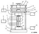
図1は、全体が1で示される、本発明の実施の形態1にかかる熱伝導率測定装置の構成図である。熱伝導率測定装置1は、測定対象物8を挟持する加熱側挟持部材7および冷却側挟持部材9と、加熱ブロックユニット5と、冷却ブロックユニット6と、押圧力調整用ネジ14などで構成される。Embodiment 1
FIG. 1 is a block diagram of a thermal conductivity measuring apparatus according to a first embodiment of the present invention, generally indicated by 1. The thermal conductivity measuring apparatus 1 includes a heating
加熱側挟持部材7および冷却側挟持部材9は、同じ材質を用いて同じ形状となるように構成され、測定対象物8と接触する接触端面および該接触端面とは反対にある遠位端面を有するような立体形状、例えば、円柱形状、角柱形状に形成される。その材質として、比較的高い熱伝導率を有する材料、例えば、銅、アルミニウムを用いることにより、測定対象物8の熱物性を測定できる。その他の材料として、アルミニウム合金、ステンレス鋼なども同様に使用できる。 The heating
加熱ブロックユニット5は、比較的高い熱伝導率を有する材料、例えば、例えば、銅、アルミニウムなどで形成され、加熱側挟持部材7の遠位端面に当接する当接端面を有する金属ブロックと、加熱素子、例えば、セラミックヒーター、カートリッジヒーターなどで構成される。金属ブロックは、熱を拡散して温度を均等にする機能を有し、加熱素子との接合箇所には、接触熱抵抗を低減するための熱伝導グリスが必要に応じて塗布される。加熱素子は、発熱量を制御するための加熱ブロックユニット制御機器18と接続される。 The
冷却ブロックユニット6は、比較的高い熱伝導率を有する材料、例えば、銅、アルミニウムなどで形成され、冷却側挟持部材9の遠位端面に当接する当接端面を有する金属ブロックと、冷却素子、例えば、水冷冷却ユニット、ペルチェ素子、ヒートシンクと冷却ファンの組合せなどで構成される。金属ブロックは、熱を拡散して温度を均等にする機能を有し、冷却素子との接合箇所には、接触熱抵抗を低減するための熱伝導グリスが必要に応じて塗布される。冷却素子は、排熱量を制御するための冷却ブロックユニット制御機器19と接続される。 The
なお、加熱ブロックユニット5の金属ブロックと加熱側挟持部材7との間、および冷却側挟持部材9と冷却ブロックユニット6の金属ブロックとの間には、接触熱抵抗を低減するために、熱伝導グリス10がそれぞれ塗布されている。 In order to reduce the contact thermal resistance between the metal block of the
こうした構成において、加熱ブロックユニット5で発生した熱が、加熱側挟持部材7に伝達され、測定対象物8を通って、冷却側挟持部材9に伝達され、冷却ブロックユニット6において排出される。このように熱が一定方向に通過する際、各部材の熱伝導率および部材間の接触熱抵抗の相違に応じて、温度勾配が形成されるようになる。 In such a configuration, the heat generated in the
加熱側挟持部材7および冷却側挟持部材9の側面には、長手方向に沿って複数の孔が形成される。各孔には、温度センサとして熱電対4が挿入され、温度測定点が挟持部材7、9の軸心に一致するように固定される。これら複数の熱電対4によって垂直位置に対応した温度分布が測定可能になり、これらの測定値は、温度測定用機器3に入力され、温度の常時モニタリングが可能である。これらの測定値から、測定対象物8を通過した熱量を算出し、測定対象物8の熱物性値、部材間の接触熱抵抗を算出することができる。こうした演算機能は、温度測定用機器3に内蔵してもよく、ネットワークで接続された外部コンピュータに搭載してもよい。 A plurality of holes are formed on the side surfaces of the heating
冷却ブロックユニット6は、土台17の中央に設置される。土台17の端部には、複数(図1では2本)のシャフト15が立設される。土台17の上方には、支持板12がシャフト15の案内によって垂直方向に変位可能なように設けられる。加熱ブロックユニット5は、支持板12に取り付けられる。シャフト15の上端には、上板16が固定される。
こうした複数のシャフト15を設けることによって、加熱ブロックユニット5、加熱側挟持部材7、測定対象物8、冷却側挟持部材9、冷却ブロックユニット6の垂直アライメントを確保することができる。The
By providing such a plurality of
熱伝導率測定装置1はさらに、加熱側挟持部材7および冷却側挟持部材9を介して、測定対象物8に加わる押圧力を調整するために押圧力調整機構を備える。押圧力調整機構は、加熱ブロックユニット5の上部に設置され、加熱ブロックユニット5を支持する支持板12と、支持板12の上に設置され、押圧力をモニタリングするためのロードセル11と、ロードセル11の上に設置され、ロードセル11に押圧力を伝えるためのスペーサ13と、上板16に固定され、スペーサ13を介してロードセル11に押圧力を加えるための押圧力調整用ネジ14などで構成される。ロードセル11によって測定された押圧力は、測定制御機器2に入力され、押圧力の常時モニタリングが可能である。 The thermal conductivity measuring device 1 further includes a pressing force adjusting mechanism for adjusting the pressing force applied to the
次に、押圧力の調整手法について説明する。測定対象物8の熱物性を測定する際、加熱ブロックユニット5から与えた熱は、加熱側挟持部材7、測定対象物8、冷却側挟持部材9を通過し、冷却ブロックユニット6に到達する。この通過する熱によって、加熱ブロックユニット5、加熱側挟持部材7、測定対象物8、冷却側挟持部材9、冷却ブロックユニット6の各部材の温度は上昇する。各部材の温度上昇に伴い、各部材は膨張し、ロードセル11に加わる押圧力は測定中に変化する。測定対象物8の熱物性測定では、測定対象物8に加わる押圧力を一定に制御する必要があるため、表示された押圧力に応じて、押圧力調整用ネジ14を調整する必要がある。ここで、所定の押圧力からの変動が±5%、好ましくは、所定の押圧力からの変動が±1%であれば測定対象物の熱物性を精度良く測定可能である。よって、本発明での「一定の押圧力」は、所定の押圧力からの変動が±5%、より好ましくは、±1%の範囲を意味する。そのためロードセル11に加わった押圧力をフィードバックして押圧力調整用ネジ14を調整し、押圧力を所定の一定値に制御する押圧力制御装置を設けることが好ましい。これにより手動作業を省いて、測定の自動化が可能となる。なお、支持板12、スペーサ13は充分な剛性を有する金属で構成することが望ましい。 Next, a method of adjusting the pressing force will be described. When measuring the thermal properties of the
また、図2に示すように、加熱ブロックユニット5と支持板12との間に断熱板20を設けることが好ましい。これにより加熱ブロックユニット5から支持板12への伝熱量を低減させることができるため、加熱側挟持部材7を介して測定対象物8に伝わる熱量を増加できる。 Further, as shown in FIG. 2, it is preferable to provide a
測定対象物8の熱物性を測定する場合、測定対象物8の厚み情報も重要となる。図3に示すように、測定状態での加熱側挟持部材7、測定対象物8、冷却側挟持部材9の合計厚みを表示できる厚み表示機器21を設けてもよい。厚み表示機器21は、レーザ距離計、光学スケール、磁気スケールなどで構成できる。ただし、図3に示す位置でなくても、測定対象物8の厚みが算出できる位置および機構であれば、この限りではない。加熱側挟持部材7、冷却側挟持部材9の厚みをノギス、マイクロメータなどにより事前に測定しておくことで、厚み表示機器21に表示された厚みから、測定対象物8のより正確な厚みを算出することが可能となる。 When measuring the thermophysical properties of the
次に、挟持部材の形状について説明する。加熱側挟持部材7および冷却側挟持部材9の形状は、例えば、直径10mm〜30mm、高さ30〜100mmの円柱形状とすることで、測定対象物8の熱物性値、部材間の接触熱抵抗を正確に精度良く測定することが可能である。四角柱形状などでも同様の精度で測定できる。 Next, the shape of the holding member will be described. The shapes of the heating
図1に戻って、加熱側挟持部材7および冷却側挟持部材9の接触端面は、平坦に加工され、加工面の表面粗さが小さいほど好ましい。実験では算術平均粗さRa=0.8μm程度に仕上げることで、測定対象物の正確な熱物性を測定することが可能であった。ただし、表面粗さはこの値に限定されるものではない。 Returning to FIG. 1, the contact end surfaces of the heating
測定対象物8は、加熱側挟持部材7および冷却側挟持部材9の接触端面の間に挿入、固定される。測定対象物8が流体である場合、ディスペンサ、スクリーン印刷により、規定の厚みに調整されて、加熱側挟持部材7と冷却側挟持部材9との間に塗布される。なお、加熱側挟持部材7と冷却側挟持部材9は、測定対象物8自体の粘着力、接着力によって固定されてもよく、もしくは粘着テープなどの補助部材を使用して固定してもよい。 The
また、加熱側挟持部材7および冷却側挟持部材9の表面から空気への熱伝達による放熱を低減するために、挟持部材の周囲に断熱材を巻きつけてもよい。測定対象物8の熱物性測定時には、測定対象物8が挟み込まれた加熱側挟持部材7および冷却側挟持部材9は一体化して冷却ブロックユニット6上に設置され、その後、加熱ブロックユニット5と冷却ブロックユニット6で挟み込まれる。さらに、ロードセル11を含む押圧力調整機構である押圧力調整用ネジ14を締め付けることで、加熱側挟持部材7、測定対象物8、冷却側挟持部材9には一定の押圧力が加えられた状態となり、この状態で熱物性の測定を開始する。 Further, in order to reduce the heat radiation due to the heat transfer from the surfaces of the heating
さらに、加熱側挟持部材7の加熱ブロックユニット5と接触する遠位端面および冷却側挟持部材9の冷却ブロックユニット6と接触する遠位端面は、それぞれ平面R形状(凸型円筒面)、または球面R形状(凸型球面)が設けられている。 Furthermore, the distal end surface of the heating
従来は、これらの遠位端面が平坦であることから、測定対象物8の熱物性を正確に測定するためには、熱が加熱側挟持部材7、測定対象物8、冷却側挟持部材9を通過する際に、加熱側挟持部材7および冷却側挟持部材9の面内方向(軸に垂直な面)の温度分布が、図5の等温線グラフに示すように、熱が偏りなく軸中心対称に通過し、面内の温度バラつきをできる限り小さくする必要があった。このグラフにおいて、符号25は熱電対4の温度測定点を示し、符号26は特定温度の等温線を示す。 Conventionally, since these distal end surfaces are flat, in order to accurately measure the thermal properties of the
このように加熱ブロックユニット5から加熱側挟持部材7、測定対象物8、冷却側挟持部材9、冷却ブロックユニット6の軸中心に熱が通過するためには、加熱側挟持部材7、測定対象物8、冷却側挟持部材9の3部材の軸が一致した状態、即ち加熱側挟持部材7および冷却側挟持部材9の軸芯と測定対象物8の中心軸とが一直線上になるように設置される必要がある。 As described above, in order for heat to pass from the
しかし、加熱ブロックユニット5および冷却ブロックユニット6に比べて、加熱側挟持部材7および冷却側挟持部材9はより小さい。このため、押圧力調整用ネジ14を調整して加熱側挟持部材7、測定対象物8、冷却側挟持部材9の各部材に押圧力を加えた際に、加熱側挟持部材7、測定対象物8、冷却側挟持部材9の3部材の軸がズレてしまうことが考えられる。実際には、機械加工、表面処理などで作製される加熱部材の当接端面、冷却部材の当接端面の平行度、平面度を考えると、加熱側挟持部材7、測定対象物8、冷却側挟持部材9の3部材の軸は、一直線にはならず、大小はあるものの少なからずズレていることが通常である。 However, compared with the
図4Aは、その一例として、加熱ブロックユニット5の金属ブロックの平行度が出ていない例、即ち、金属ブロックの下面が水平で無い場合を示す。加熱ブロックユニット5の金属ブロックの平行度が出ていない場合、押圧力を加えると、加熱側挟持部材7の遠位端面は金属ブロックの平行度が出ていない当接端面に倣ってしまい、加熱側挟持部材7の当接端面と測定対象物は片当たりしてしまう。 As an example, FIG. 4A shows an example in which the parallelism of the metal block of the
図4Aに示すように加熱側挟持部材7の当接端面と測定対象物8が片当たりしている場合、矢印50で示すように、加熱側挟持部材7、測定対象物8、冷却側挟持部材9を通過する熱流束は、軸中心に対象ではなく、片側に偏ってしまう。その結果、図6に示すように、熱が加熱側挟持部材7、測定対象物8および冷却側挟持部材9を中心から偏って通過してしまい、測定対象物8の面内方向の温度バラつきが大きくなり、測定対象物8の正確な熱物性測定ができない。このため測定対象物8の熱物性を正確に測定するためには、加熱側挟持部材7と接触する加熱ブロックユニット5および冷却側挟持部材9と接触する冷却ブロックユニット6において、それぞれの平行度が出ていることなどを確認、調整する必要がある。この場合、熟練した作業が要求され、測定のセッティング時間、調整時間が長くなる傾向がある。 As shown in FIG. 4A, when the contact end face of the heating
代替として、調整作業を省いて、各部材中の熱の偏りを測定するユニットを追加し、測定した熱の偏りに応じた補正を計算上で行うことも考えられる。この場合、複雑な計算が要求され、測定精度の低下も生じ得る。 As an alternative, it is also conceivable to omit the adjustment operation, add a unit for measuring the heat bias in each member, and calculate the correction corresponding to the measured heat bias. In this case, complicated calculations are required, and a reduction in measurement accuracy may also occur.
図7Aは、加熱ブロックユニットの5金属ブロックの当接端面の平行度が出ていない場合に、本発明を適用した一例を示す。図7A(a)に示すように、押圧力を加えた初期段階では、加熱ブロックユニット5の当接端面の平行度が出ていないため、加熱側挟持部材7が傾いてしまい、測定対象物8に片辺りしてしまう。この場合、加熱側挟持部材7、測定対象物8、冷却側挟持部材9を通過する熱流束が偏り、測定対象物8の面内方向の温度バラつきが大きいため、測定対象物8の正確な熱物性は測定できない。しかし、本発明では加熱側挟持部材7および冷却側挟持部材9の遠位端面に、平面R形状(凸型円筒面)または球面R形状(凸型球面)を設けているため、測定対象物8を挟み込んだ加熱側挟持部材7、測定対象物8および冷却側挟持部材9を冷却ブロックユニット6および加熱ブロックユニット5で挟み込み、押圧力調整用ネジ14によって、加熱ブロックユニット5、加熱側挟持部材7、測定対象物8、冷却側挟持部材9および冷却ブロックユニット6に押圧力を加えた際に、平面R形状または球面R形状を遠位端面に設けた加熱側挟持部材7および冷却側挟持部材9は安定な姿勢になろうとするため、加熱ブロックユニット5の表面に倣う動作が自然に発生する(図7A(b))。ここで、符号27は、押圧力調整用ネジ14から加わる押圧力ベクトルを示す。符号28は、押圧力が加わった際に加熱側挟持部材7の湾曲面に働く水平方向の押圧力ベクトルを示す。 FIG. 7A shows an example to which the present invention is applied when the parallelism of the contact end face of the five metal blocks of the heating block unit is not obtained. As shown in FIG. 7A (a), in the initial stage of application of the pressing force, the parallelism of the contact end face of the
この動作によって、図7A(c)に示すように、特別な調整なしに、押圧力調整用ネジ14による押圧力を加えることだけで、加熱側挟持部材7、測定対象物8、冷却側挟持部材9の3部材の軸を一致させることができ、熱は、加熱側挟持部材7、測定対象物8および冷却側挟持部材9の軸対称に通過することが可能なり(図5参照)、測定対象物8の面内方向の温度バラつきを大幅に低減することができる。これにより、測定対象物8の正確な熱物性が特別な調整なしに効率的に測定可能になる。 By this operation, as shown in FIG. 7A (c), the heating
また、加熱ブロックユニット5から加熱側挟持部材7、測定対象物8、冷却側挟持部材9、冷却ブロックユニット6の軸中心に熱が通過するためには、加熱側挟持部材7、測定対象物8、冷却側挟持部材9を測定装置全体の軸(鉛直方向の軸)に対して傾くことなく設置されることが好ましい。 Further, in order for heat to pass from the
しかし、加熱ブロックユニット5および冷却ブロックユニット6に比べて、加熱側挟持部材7および冷却側挟持部材9はより小さい。このため、図4Bに示すように、押圧力調整用ネジ14を調整して加熱側挟持部材7、測定対象物8、冷却側挟持部材9の各部材に押圧力を加えた際に、装置本体の軸に対して傾いてしまうことが考えられる。 However, compared with the
部材が傾斜した場合、図6に示すように、熱が加熱側挟持部材7、測定対象物8および冷却側挟持部材9を中心から偏って通過してしまい、測定対象物8の正確な熱物性測定ができない。このため加熱側挟持部材7と接触する加熱ブロックユニット5および冷却側挟持部材9と接触する冷却ブロックユニット6において、それぞれの平行度が出ていることなどを確認、調整する必要がある。この場合、熟練した作業が要求され、測定のセッティング時間、調整時間が長くなる傾向がある。 When the member is inclined, as shown in FIG. 6, the heat passes through the heating
この場合も、代替として、調整作業を省いて、各部材中の熱の偏りを測定するユニットを追加し、測定した熱の偏りに応じた補正を計算上で行うことも考えられるが、複雑な計算が要求され、測定精度の低下も生じ得る。 Also in this case, as a substitute, it is possible to add a unit for measuring the heat bias in each member, omitting adjustment work, and performing correction on the basis of the measured heat bias on the calculation, but this is complicated Calculations are required and may also reduce measurement accuracy.
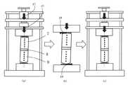
本実施の形態では、図7B(a)に示すように、加熱ブロックユニット5および冷却ブロックユニット6の当接端面を平面形状とし、加熱側挟持部材7および冷却側挟持部材9の遠位端面に、平面R形状(凸型円筒面)または球面R形状(凸型球面)を設けることによって、自動調心機構を実現している。これにより測定対象物8を挟み込んだ加熱側挟持部材7、測定対象物8および冷却側挟持部材9を冷却ブロックユニット6および加熱ブロックユニット5で挟み込み、押圧力調整用ネジ14によって、加熱ブロックユニット5、加熱側挟持部材7、測定対象物8、冷却側挟持部材9および冷却ブロックユニット6に押圧力を加えた際に、加熱側挟持部材7および冷却側挟持部材9の遠位端面に設けた平面R形状または球面R形状により、測定対象物8を挟み込んだ加熱側挟持部材7、測定対象物8および冷却側挟持部材9は、図7B(b)に示すように、加熱ブロックユニット5および冷却ブロックユニット6の表面に倣う動作が自然に発生する。ここで、符号27は、押圧力調整用ネジ14から加わる押圧力ベクトルを示す。符号28は、押圧力が加わった際に加熱側挟持部材7の湾曲面に働く水平方向の押圧力ベクトルを示す。符号29は、押圧力が加わった際に冷却側挟持部材9の湾曲面に働く水平方向の押圧力ベクトルを示す。 In the present embodiment, as shown in FIG. 7B (a), the abutting end surfaces of the
この動作によって、図7B(c)に示すように、特別な調整なしに、押圧力調整用ネジ14による押圧力を加えることだけで、加熱側挟持部材7、測定対象物8、冷却側挟持部材9の各部材の軸を、熱伝導率測定装置本体の軸あわせることができる。この結果、図5に示すように、熱が加熱側挟持部材7、測定対象物8および冷却側挟持部材9の中心を通過し、測定対象物8の正確な熱物性が測定可能になる。 By this operation, as shown in FIG. 7B (c), the heating
ここでは、加熱側挟持部材7および冷却側挟持部材9の遠位端面に、平面R形状(凸型円筒面)または球面R形状(凸型球面)を設けたが、これは押圧力を加え、安定な姿勢になろうとする際に働く摩擦力をできる限り小さくし、押圧力に伴って発生する押圧力ベクトルをできる限り大きくするためである。また、高い測定精度を確保するためには、加熱側挟持部材7、測定対象物8、冷却側挟持部材9を通過する熱量を大きくし、各熱電対での測定温度を高くする、つまり温度勾配を大きくすることが望ましい。これは、通過する熱量を大きくし、各熱電対での測定温度を高くすることで、熱電対での測定温度バラつきの影響(例えばK熱電対、クラス1の場合±1.5℃)を抑制することができるためである。通過熱量が小さく、温度勾配が小さい場合には、この測定温度バラつきが測定対象物の熱物性に大きく影響してしまう。また、熱伝導グリス10(図1参照)の厚みが厚い場合、熱伝導グリスの熱抵抗が大きくなってしまい、加熱側挟持部材7、冷却側挟持部材9の各熱電対の測定温度が低くなるため、測定精度が悪化することが懸念される。このため、熱伝導グリスはできる限り薄く塗布する必要がある。 Here, a flat R shape (convex cylindrical surface) or a spherical R shape (convex spherical surface) is provided on the distal end surfaces of the heating
実験では、挟持部材7、9の形状をφ15mm、高さ30mmの円柱とし、遠位端面に曲率半径Rの凸型球面を形成した場合、測定対象物8、および部材間の接触熱抵抗の正確な熱物性値を測定することが可能であった。 In the experiment, when the shape of the holding
即ち、挟持部材の垂直断面を表す図8に示すように、加熱側挟持部材7、冷却側挟持部材9の直径をA、遠位端面の曲率半径をRとした場合、挟持部材7、9が上述の構成であれば、凸側球面形状において、挟持部材の加熱ブロック表面に倣う部分、つまりR−sqrt(R2−(A/2)2)の大きさが、
0.01≦R−sqrt(R2−(A/2)2)≦0.1、より好ましくは、
0.02≦R−sqrt(R2−(A/2)2)≦0.05
を満たす大きさであれば、測定対象物8の熱物性を精度良く測定可能であった。That is, as shown in FIG. 8 showing a vertical cross section of the holding member, when the diameters of the heating
0.01 ≦ R−sqrt (R2 − (A / 2)2 ) ≦ 0.1, more preferably
0.02 ≦ R−sqrt (R2 − (A / 2)2 ) ≦ 0.05
If the size satisfies the following condition, it is possible to measure the thermophysical properties of the measuring
実験は、挟持部材の形状をφ15mm、つまり上記A=15mm、凸側球面形状をR563、R1406(半径Rが563mmと1406mm)でそれぞれ行った。
R563の場合、R−sqrt(R2−(A/2)2=0.02、
R1406の場合、R−sqrt(R2−(A/2)2=0.05、
となる。ただし、曲率半径Rの大きさにこれらに限られるものではなく、適宜変更できる。The experiment was performed with the shape of the holding member being φ 15 mm, that is, the above-mentioned A = 15 mm, and the convex spherical surface shape being R563 and R1406 (radius R of 563 mm and 1406 mm).
ForR563, R-sqrt (R 2 - (A / 2) 2 = 0.02,
In the case of R 1406, R-sqrt (R2- (A / 2)2 = 0.05,
It becomes. However, the size of the radius of curvature R is not limited to these, and can be changed as appropriate.
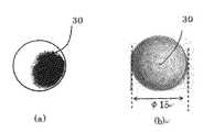
加熱側挟持部材7および冷却側挟持部材9の遠位端面に、平面R形状または球面R形状を設けた場合の、接触状態の効果確認(例えば、圧力分布)をφ15、高さ30mmの円柱を用いて行った結果として図9に示す。図9(a)では、遠位端面が平坦である場合、遠位端面の接触エリア30において部分接触となるが、図9(b)では、遠位端面に球面R形状を設けることにより、接触エリア30において全面接触となることが分かる。 A cylinder with a diameter of φ15 and a height of 30 mm is used to confirm the effect of contact (for example, pressure distribution) when a flat R shape or a spherical R shape is provided on the distal end surface of heating
上述のケースでは、加熱側挟持部材7と冷却側挟持部材9の間に測定対象物8を挟み込み、測定対象物8の熱物性値を測定している。これらに加えて、測定対象物8を挟み込まない状態での測定にも大きな効果を発揮する。具体的には、測定対象物8を挟み込まず、加熱側挟持部材7と冷却側挟持部材9だけで、部材間の押圧力と接触熱抵抗を算出する場合である。接触熱抵抗を算出する場合、加熱側挟持部材7と冷却側挟持部材9の間の接触状態が測定結果に大きな影響を与える。本発明のように、加熱側挟持部材7および冷却側挟持部材9の遠位端面に平面R形状または球面R形状を設けることによって、図9に示すように、特別な調整なしに、両部材間が均一に接触する理想的な接触状態が得られる。この状態で接触熱抵抗を測定することで、接触熱抵抗を効率的に、精度良く測定することが可能となる。 In the above-described case, the object to be measured 8 is sandwiched between the heating
なお、熱伝導グリスは、図1において加熱ブロックユニット5の当接端面と加熱側挟持部材7の遠位端面と間に配置した例を示しているが、好ましくは、加熱ブロックユニット5の当接端面に加熱側挟持部材7の遠位端面の頂部を包含できるグリス凹みを設けておけば、熱伝導グリスが加圧と共に押し出されて、また測定時の加熱と共に流動性が上がり流れ出すような不具合を防止できる。また、調整作業の際、挟持部材の水平方向の位置の自由度が拘束されるため、位置決めが容易になるという利点を奏する。 The heat conduction grease is shown in FIG. 1 as being disposed between the contact end face of the
熱伝導グリスは、内包するフィラーによって律束されある程度の厚みを有し、かつ熱伝導率は数W/mK程度であるため、ある程度の熱抵抗を有する。しかし本熱伝導率測定方法においては、熱流束は、図示されている複数の熱電対を用いて測定対象物を通過した熱量を算出しているため、測定対象には熱伝導グリスの影響は現れない。このため、高精度な測定が可能である。 The heat conductive grease has a certain degree of thickness controlled by the filler contained therein, and the thermal conductivity is about several W / mK, so it has a certain degree of thermal resistance. However, in this thermal conductivity measurement method, the heat flux is calculated using the plurality of illustrated thermocouples to calculate the amount of heat passing through the measurement object, so the effect of the heat conduction grease appears on the measurement object Absent. Therefore, highly accurate measurement is possible.
また上述の例では、加熱側挟持部材7および冷却側挟持部材9の両方の遠位端面に凸型の湾曲形状を付与した例を示しているが、いずれか一方の遠位端面だけに凸型の湾曲形状を付与しても精度上は問題ない。 In the above-mentioned example, although the example which gave convex curve shape to the distal end face of both heating
また上述の例では、熱伝導率の測定に用いる例を示しているが、熱伝導率の逆数である熱抵抗率の測定にも適用できる。 Moreover, although the example used for the measurement of thermal conductivity is shown in the above-mentioned example, it is applicable also to the measurement of the thermal resistivity which is an inverse number of thermal conductivity.
なお、本発明の実施の形態1では、例えば図1に示すように、シャフト15(図1は2本のシャフト15を用いた2軸固定)を用いて加熱ブロックユニット5、加熱側挟持部材7、測定対象物8、冷却側挟持部材9、および冷却ブロックユニット6の垂直アライメントを確保しているが、本発明はこのような構造に限定されるものではない。つまり、本発明である、加熱側挟持部材7および冷却側挟持部材9の遠位端面に、平面R形状(凸型円筒面)または球面R形状(凸型球面)を設けることで、加熱側挟持部材7、測定対象物8、冷却側挟持部材9がたとえ傾いた場合であっても、加熱側挟持部材7と測定対象物8との間、測定対象物8と冷却側挟持部材9との間の片辺りを防止でき、全面接触とすることができる。このため、図1のような複数のシャフト15を用いなくても、測定対象物8の熱物性を精度良く測定することが可能となる。 In the first embodiment of the present invention, for example, as shown in FIG. 1, the
図10は、バイス55を用いた1軸固定の測定装置の構成図であり、図10中、図1と同一符号は、同一または相当箇所を示す。本発明を用いることにより、図10に示すようにバイス55などを用いた1軸固定であっても、測定対象物8の熱物性を精度良く測定することが可能となる。 FIG. 10 is a block diagram of a measurement apparatus fixed to one axis using the
実施の形態2.
図11は、本発明の実施の形態2にかかる熱伝導率測定装置の構成図であり、図11中、図1と同一符合は、同一または相当箇所を示す。本実施の形態2に係る熱伝導率測定装置では、加熱側挟持部材7および冷却側挟持部材9の遠位端面、ならびに加熱ブロックユニット5および冷却ブロックユニット6の当接端面が、図1の熱伝導率測定装置とは異なる形状を有する。Second Embodiment
FIG. 11 is a block diagram of a thermal conductivity measuring apparatus according to a second embodiment of the present invention. In FIG. 11, the same reference numerals as in FIG. 1 indicate the same or corresponding parts. In the thermal conductivity measuring apparatus according to the second embodiment, the distal end surfaces of the heating
具体的には、加熱側挟持部材7および冷却側挟持部材9の遠位端面を平面形状とし、一方で、加熱ブロックユニット5および冷却ブロックユニット6の当接端面に、平面R形状(凸型円筒面)または球面R形状(凸型球面)を設けることによって、測定対象物8の面内方向の温度バラつきを抑制している。 Specifically, the distal end surfaces of the heating
本実施の形態2では、加熱ブロックユニット5および冷却ブロックユニット6の当接端面に設けた平面R形状(凸型円筒面)または球面R形状(凸型球面)により、測定対象物8を挟み込んだ加熱側挟持部材7、測定対象物8および冷却側挟持部材9を冷却ブロックユニット6上に設置し、押圧力調整用ネジ14で押圧力を加えた際に、加熱側挟持部材7、測定対象物8、冷却側挟持部材9は安定な姿勢になろうする。即ち、実施の形態1の図7Bの場合と同様に、金属ブロック表面に設けた平面R形状または球面R形状により、特別な調整なしに押圧力ベクトル(図7Bの28、29)が自然に発生する。この結果、熱は、加熱側挟持部材7、測定対象物8および冷却側挟持部材9を軸対称に通過することが可能となり(図5)、測定対象物8の面内方向の温度バラつきが小さくなる。このため、測定対象物8の正確な熱物性が特別な調整なしに、かつ効率的に測定可能となる。 In the second embodiment, the object to be measured 8 is sandwiched by a flat R shape (convex cylindrical surface) or a spherical R shape (convex spherical surface) provided on the abutting end surfaces of the
また、図12に示すように、加熱ブロックユニット5の遠位端面および冷却ブロックユニット6の遠位端面を平面R形状(凸型円筒面)または球面R形状(凸型球面)を設けることによっても、押圧力を加えることで、加熱側挟持部材7、測定対象物8、冷却側挟持部材9の軸を一致させることができ、測定対象物の面内方向の温度バラつきを最大限抑制することが可能となる。このため、測定対象物の熱物性を精度良く、効率的に測定することが可能となる。 Further, as shown in FIG. 12, the distal end surface of the
加熱ブロックユニット5および冷却ブロックユニット6の当接端面に設けた平面R形状または球面R形状の曲率半径Rは大きいほど、面倣い効果がより効率的に発揮される。 The larger the curvature radius R of the flat R-shape or the spherical R-shape provided on the abutting end surfaces of the
下記(表1)は、加熱側挟持部材7および冷却側挟持部材9の各遠位端面ならびに加熱ブロックユニット5および冷却ブロックユニット6の各当接端面について、凸型湾曲形状および平面形状の組合せと面倣い効果との関係を示す。従来は、全ての端面が平面形状であり(No.1)、面倣い効果は現れない。一方、全ての端面のうち少なくとも1つが凸型湾曲形状で、残りが平面形状である場合(No.2〜10)、面倣い効果が現れており、一般には凸型湾曲形状である端面の数が増加するほど、面倣い効果も増加することになる。 The following (Table 1) shows a combination of a convex curved shape and a planar shape for each distal end surface of the heating

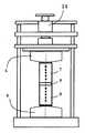
また、図13に示すように、支持板12とスペーサ13との間にあるシャフト15に複数のコイルばね33を装着することによって、支持板12およびスペーサ13がバネ力によって平行に維持された状態で、加熱ブロックユニット5に押圧力を印加できる。このため、加熱側挟持部材7に対して軸が合った状態で押圧力を印加することが可能となる。 Further, as shown in FIG. 13, by mounting a plurality of coil springs 33 on the
さらに、図14に示すように、支持板12の下方にあるシャフト15にばね受け34を固定し、支持板12とばね受け34との間にあるシャフト15に複数のコイルばね33を装着することによっても同様に、加熱側挟持部材7に対して軸が合った状態で押圧力を印加することが可能となる。 Further, as shown in FIG. 14, a
なお、加熱側挟持部材7の遠位端面、冷却側挟持部材9の遠位端面、加熱ブロックユニット5の当接端面、加熱ブロックユニット5の遠位端面、冷却ブロックユニット6の当接端面、および冷却ブロックユニット6の遠位端面のうち少なくとも1つを凸型の湾曲形状(平面R形状または球面R形状)としても良い。また、加熱側挟持部材7の遠位端面、加熱ブロックユニット5の当接端面、および加熱ブロックユニット5の遠位端面のうちの少なくとも1つ、並びに冷却側挟持部材9の遠位端面、冷却ブロックユニット6の当接端面、冷却ブロックユニット6の遠位端面のうち少なくとも1つを凸型の湾曲形状(平面R形状または球面R形状)としても良い。 The distal end face of the heating
1 熱伝導率測定装置、2 測定制御機器、3 温度測定用機器、4 熱電対、5 加熱ブロックユニット、6 冷却ブロックユニット、7 加熱側挟持部材、8 測定対象物、9 冷却側挟持部材、10 熱伝導グリス、11 ロードセル、12 支持板、13 スペーサ、14 押圧力調整用ネジ、15 シャフト、16 上板、17 土台、18 加熱ブロックユニット制御機器、19 冷却ブロックユニット制御機器、20 断熱板、21 厚み表示機器、25 温度測定点、26 等温線、27〜29 押圧力ベクトル、30 接触エリア、33 コイルばね、34 ばね受け、55 バイス。 DESCRIPTION OF SYMBOLS 1 Thermal conductivity measuring apparatus, 2 Measurement control apparatus, 3 Temperature-measurement apparatus, 4 Thermocouple, 5 Heating block unit, 6 Cooling block unit, 7 Heating side holding member, 8 Measurement object, 9 Cooling side holding member, 10 Thermal conduction grease, 11 load cell, 12 support plate, 13 spacer, 14 screw for adjusting pressure, 15 shaft, 16 upper plate, 17 base, 18 heating block unit control device, 19 cooling block unit control device, 20 heat insulating plate, 21 Thickness display device, 25 temperature measurement points, 26 isotherms, 27 to 29 pressing force vectors, 30 contact areas, 33 coil springs, 34 spring bearings, 55 vise.
Claims (11)
Translated fromJapanese測定対象物と接触する接触端面および該接触端面とは反対側にある遠位端面を有し、前記第1挟持部材とともに測定対象物を挟持する第2挟持部材と、
前記第1挟持部材の遠位端面に当接する当接端面および該当接端面とは反対側にある遠位端面を有し、第1挟持部材を加熱する加熱部材と、
前記第2挟持部材の遠位端面に当接する当接端面および該当接端面とは反対側にある遠位端面を有し、第2挟持部材を冷却する冷却部材と、
前記第1挟持部材および前記第2挟持部材に設けられた複数の温度センサと、
前記第1挟持部材、前記第2挟持部材および測定対象物に押圧力を印加する押圧力印加機構とを含み、
前記第1挟持部材の遠位端面、前記第2挟持部材の遠位端面、前記加熱部材の当接端面、前記加熱部材の遠位端面、前記冷却部材の当接端面、および前記冷却部材の遠位端面のうちの少なくとも1つが凸型の湾曲形状を有することを特徴とする熱伝導率測定装置。A first clamping member having a contact end face in contact with the object to be measured and a distal end face opposite to the contact end face;
A second holding member having a contact end surface in contact with the object to be measured and a distal end surface opposite to the contact end surface and holding the object to be measured together with the first holding member;
A heating member for heating the first holding member, the heating member having an abutting end surface abutting the distal end surface of the first holding member and a distal end surface opposite to the holding end surface;
A cooling member having an abutting end surface abutting on a distal end surface of the second holding member and a distal end surface opposite to the abutting end surface, and cooling the second holding member;
A plurality of temperature sensors provided on the first holding member and the second holding member;
A pressing force application mechanism that applies a pressing force to the first holding member, the second holding member, and the object to be measured;
The distal end face of the first clamping member, the distal end face of the second clamping member, the abutting end face of the heating member, the distal end face of the heating member, the abutting end face of the cooling member, and the distal end of the cooling member A thermal conductivity measuring device characterized in that at least one of the end faces has a convex curved shape.
測定対象物と接触する接触端面および該接触端面とは反対側にある遠位端面を有し、前記第1挟持部材とともに測定対象物を挟持する第2挟持部材と、
前記第1挟持部材の遠位端面に当接する当接端面を有し、第1挟持部材を加熱する加熱部材と、
前記第2挟持部材の遠位端面に当接する当接端面を有し、第2挟持部材を冷却する冷却部材と、
前記第1挟持部材および前記第2挟持部材に設けられた複数の温度センサと、
前記第1挟持部材、前記第2挟持部材および測定対象物に押圧力を印加する押圧力印加機構とを含み、
前記第1挟持部材の遠位端面、前記第2挟持部材の遠位端面、前記加熱部材の当接端面および前記冷却部材の当接端面のうちの少なくとも1つが凸型の湾曲形状を有し、残りが平面形状を有することを特徴とする熱伝導率測定装置。A first clamping member having a contact end face in contact with the object to be measured and a distal end face opposite to the contact end face;
A second holding member having a contact end surface in contact with the object to be measured and a distal end surface opposite to the contact end surface and holding the object to be measured together with the first holding member;
A heating member having an abutting end surface that abuts on a distal end surface of the first holding member, and heating the first holding member;
A cooling member that has an abutting end surface that abuts on a distal end surface of the second holding member, and that cools the second holding member;
A plurality of temperature sensors provided on the first holding member and the second holding member;
A pressing force application mechanism that applies a pressing force to the first holding member, the second holding member, and the object to be measured;
At least one of the distal end surface of the first holding member, the distal end surface of the second holding member, the abutting end surface of the heating member, and the abutting end surface of the cooling member has a convex curved shape. A thermal conductivity measuring device characterized in that the rest has a planar shape.
前記第1挟持部材と前記第2挟持部材との間に測定対象物を挟む工程と、
前記押圧力印加機構で、前記第1挟持部材、前記第2挟持部材および測定対象物に押圧力を印加する工程と、
前記温度センサで、前記測定対象物の熱伝導率を測定する工程と、を含むことを特徴とする熱伝導率測定方法。Providing the thermal conductivity measuring device according to any one of claims 1 to 10;
Sandwiching an object to be measured between the first holding member and the second holding member;
Applying a pressing force to the first holding member, the second holding member, and the object to be measured by the pressing force application mechanism;
Measuring the thermal conductivity of the object to be measured with the temperature sensor.
Applications Claiming Priority (3)
| Application Number | Priority Date | Filing Date | Title |
|---|---|---|---|
| JP2015214380 | 2015-10-30 | ||
| JP2015214380 | 2015-10-30 | ||
| PCT/JP2016/081260WO2017073479A1 (en) | 2015-10-30 | 2016-10-21 | Thermal conductivity measurement apparatus and thermal conductivity measurement method |
Publications (2)
| Publication Number | Publication Date |
|---|---|
| JPWO2017073479A1 JPWO2017073479A1 (en) | 2018-07-12 |
| JP6509362B2true JP6509362B2 (en) | 2019-05-08 |
Family
ID=58630269
Family Applications (1)
| Application Number | Title | Priority Date | Filing Date |
|---|---|---|---|
| JP2017547770AActiveJP6509362B2 (en) | 2015-10-30 | 2016-10-21 | Thermal conductivity measuring device and thermal conductivity measuring method |
Country Status (5)
| Country | Link |
|---|---|
| US (1) | US10768127B2 (en) |
| JP (1) | JP6509362B2 (en) |
| CN (1) | CN108351313B (en) |
| DE (1) | DE112016004973B4 (en) |
| WO (1) | WO2017073479A1 (en) |
Cited By (2)
| Publication number | Priority date | Publication date | Assignee | Title |
|---|---|---|---|---|
| KR20200136553A (en)* | 2019-05-27 | 2020-12-08 | 주식회사 에스이오 | Thermal conductivity measurement system and thermal conductivity measurement method thereof |
| KR20230007756A (en)* | 2021-07-06 | 2023-01-13 | 현대로템 주식회사 | Stator Segment Heat Transfer Characteristics Test Device for Electric Machine |
Families Citing this family (12)
| Publication number | Priority date | Publication date | Assignee | Title |
|---|---|---|---|---|
| JP6682016B2 (en)* | 2017-01-16 | 2020-04-15 | 三菱電機株式会社 | Thermal conductivity measuring device and thermal conductivity measuring method |
| DE102018101906A1 (en)* | 2018-01-29 | 2019-08-01 | Freie Universität Berlin | Apparatus and method for measuring a thermal conductivity of a sample |
| TR201821033A2 (en)* | 2018-12-28 | 2020-07-21 | Dokuz Eyluel Ueniversitesi Rektoerluegue | A measuring setup. |
| CN110687159B (en)* | 2019-09-12 | 2022-06-10 | 无锡江南计算技术研究所 | Thermal resistance measuring device and method for thermal grease |
| CN110779954A (en)* | 2019-11-20 | 2020-02-11 | 上海交通大学 | Device and method for measuring contact heat conductivity coefficient in plastic deformation state |
| CN110907494B (en)* | 2019-12-12 | 2022-02-15 | 河南科技大学 | A detection system and detection method for detecting heat distribution coefficient of friction pair |
| EP3984747B1 (en)* | 2020-10-16 | 2023-03-29 | B&R Industrial Automation GmbH | Hot foil stamping machine |
| WO2023070001A1 (en)* | 2021-10-19 | 2023-04-27 | Lunar Outpost Inc. | Extendable conductor for thermal management |
| DE102022200422B3 (en) | 2022-01-14 | 2023-03-02 | Volkswagen Aktiengesellschaft | Device for determining the thermal conductivity of a test specimen |
| DE102022002808B3 (en) | 2022-08-03 | 2023-03-02 | Sew-Eurodrive Gmbh & Co Kg | Device and method for measuring a thermal conductivity of a test piece |
| KR20240042788A (en)* | 2022-09-26 | 2024-04-02 | 현대자동차주식회사 | Device for measuring thermal conductivity |
| GB2634258A (en)* | 2023-10-03 | 2025-04-09 | Popov Oleksii | Thermal conductivity measurement apparatus and method |
Family Cites Families (35)
| Publication number | Priority date | Publication date | Assignee | Title |
|---|---|---|---|---|
| US3263485A (en)* | 1964-01-30 | 1966-08-02 | Minnesota Mining & Mfg | Apparatus for determining thermal conductivity |
| US3521476A (en)* | 1966-12-27 | 1970-07-21 | Ralph K Day | Method and apparatus for measuring thermal conductivity |
| US3733887A (en)* | 1972-01-31 | 1973-05-22 | Borg Warner | Method and apparatus for measuring the thermal conductivity and thermo-electric properties of solid materials |
| JPS5250553B2 (en)* | 1973-02-12 | 1977-12-24 | ||
| PL139300B1 (en)* | 1983-04-27 | 1987-01-31 | Pan Ct Badan Molekularnych I M | Method of determination of thermal conductivity and heat storage capacity of materials and apparatus therefor |
| JP2567441B2 (en) | 1988-02-05 | 1996-12-25 | 住友電気工業株式会社 | Measuring method of thermal conductivity, measuring device and thermistor |
| FR2695475B1 (en)* | 1992-09-10 | 1994-10-21 | Univ Nantes | Conductivity meter for transient measurement of the conductivity of an injectable material or not. |
| US5838451A (en)* | 1995-12-22 | 1998-11-17 | Accuracy Microsensors, Inc. | Optoelectronic spectral analysis system |
| WO1997033161A1 (en)* | 1996-03-08 | 1997-09-12 | Holometrix, Inc. | Heat flow meter instruments |
| DE19636673C2 (en)* | 1996-09-10 | 1998-09-17 | Barbara Dipl Phys Pause | Method and device for measuring thermophysical parameters of plate-shaped samples, in particular textile fabrics, under different measuring conditions |
| US6331075B1 (en)* | 1998-05-01 | 2001-12-18 | Administrator, National Aeronautics And Space Administration | Device and method for measuring thermal conductivity of thin films |
| US6142662A (en)* | 1998-06-16 | 2000-11-07 | New Jersey Institute Of Technology | Apparatus and method for simultaneously determining thermal conductivity and thermal contact resistance |
| US6742926B1 (en)* | 2000-07-10 | 2004-06-01 | The United States Of America As Represented By The Administrator Of The National Aeronautics And Space Administration | Methods of testing thermal insulation and associated test apparatus |
| JP3858660B2 (en) | 2001-10-10 | 2006-12-20 | 株式会社日立製作所 | Measuring method of thermal resistance of resin |
| JP3723761B2 (en) | 2001-11-12 | 2005-12-07 | 松下電器産業株式会社 | Electronic component mounting equipment |
| US6923570B2 (en)* | 2003-09-11 | 2005-08-02 | Hewlett-Packard Development Company, L.P. | Thermal interface material characterizing system |
| US20060045165A1 (en)* | 2004-08-30 | 2006-03-02 | Chan Gary K | Thermal interface material characterization system and method |
| JP2006145446A (en) | 2004-11-24 | 2006-06-08 | Mitsubishi Electric Corp | Thermal conductivity measuring device and thermal conductivity measuring method |
| CN1948957A (en)* | 2005-10-13 | 2007-04-18 | 鸿富锦精密工业(深圳)有限公司 | Flowing material heat conduction performance measuring device |
| CN1955727A (en)* | 2005-10-27 | 2007-05-02 | 鸿富锦精密工业(深圳)有限公司 | Heat pipe measuring device |
| JP2007178218A (en) | 2005-12-27 | 2007-07-12 | Mitsubishi Electric Corp | Thermal resistance measuring device |
| US7517140B2 (en)* | 2006-09-27 | 2009-04-14 | Intel Corporation | Techniques for precision testing of thermal interface materials |
| JP2008309729A (en)* | 2007-06-18 | 2008-12-25 | Mitsubishi Electric Corp | Thermal conductivity measuring device and thermal conductivity measuring method |
| JP2009233727A (en) | 2008-03-28 | 2009-10-15 | Fujifilm Corp | Press machine |
| CN101393150B (en)* | 2008-10-16 | 2011-05-18 | 大连理工大学 | Solid interface contact heat exchange coefficient measurement method and apparatus based on transient method |
| JP5509195B2 (en) | 2009-03-11 | 2014-06-04 | 学校法人常翔学園 | Thermal conductivity measuring device and thermal conductivity measuring method |
| JP2011102768A (en) | 2009-11-11 | 2011-05-26 | Canon Inc | Measuring method of heat characteristic |
| JP5379760B2 (en)* | 2010-07-29 | 2013-12-25 | エスペック株式会社 | Thermal conductivity measuring device and thermal conductivity measuring method |
| CN103954648B (en)* | 2014-04-10 | 2016-03-23 | 中国矿业大学 | Device and method for measuring thermal conductivity of a hemispherical heat source steady state method |
| CN103983660B (en)* | 2014-04-30 | 2016-04-06 | 中国科学院武汉岩土力学研究所 | A kind of indoor rock sample test device of thermal conductivity coefficient |
| CN104181195B (en)* | 2014-08-28 | 2017-02-15 | 电子科技大学 | Steady-state method-based heat conductivity coefficient measurement device |
| CN104535609B (en)* | 2014-12-26 | 2018-03-09 | 怡维怡橡胶研究院有限公司 | A kind of heat conducting coefficient measurement device |
| CN104597077B (en)* | 2014-12-31 | 2017-05-10 | 技嘉科技股份有限公司 | Thermal conductivity test device and pressure fixture |
| CN105388184A (en)* | 2015-12-17 | 2016-03-09 | 北京航空航天大学 | Specimen installation fixture used for contact thermal resistance testing |
| JP6682016B2 (en)* | 2017-01-16 | 2020-04-15 | 三菱電機株式会社 | Thermal conductivity measuring device and thermal conductivity measuring method |
- 2016
- 2016-10-21CNCN201680062672.2Apatent/CN108351313B/enactiveActive
- 2016-10-21USUS15/765,751patent/US10768127B2/enactiveActive
- 2016-10-21DEDE112016004973.0Tpatent/DE112016004973B4/enactiveActive
- 2016-10-21WOPCT/JP2016/081260patent/WO2017073479A1/ennot_activeCeased
- 2016-10-21JPJP2017547770Apatent/JP6509362B2/enactiveActive
Cited By (4)
| Publication number | Priority date | Publication date | Assignee | Title |
|---|---|---|---|---|
| KR20200136553A (en)* | 2019-05-27 | 2020-12-08 | 주식회사 에스이오 | Thermal conductivity measurement system and thermal conductivity measurement method thereof |
| KR102257190B1 (en) | 2019-05-27 | 2021-06-01 | 주식회사 에스이오 | Thermal conductivity measurement system and thermal conductivity measurement method thereof |
| KR20230007756A (en)* | 2021-07-06 | 2023-01-13 | 현대로템 주식회사 | Stator Segment Heat Transfer Characteristics Test Device for Electric Machine |
| KR102494392B1 (en)* | 2021-07-06 | 2023-01-31 | 현대로템 주식회사 | Stator Segment Heat Transfer Characteristics Test Device for Electric Machine |
Also Published As
| Publication number | Publication date |
|---|---|
| DE112016004973B4 (en) | 2021-10-14 |
| CN108351313B (en) | 2020-09-01 |
| JPWO2017073479A1 (en) | 2018-07-12 |
| US10768127B2 (en) | 2020-09-08 |
| DE112016004973T5 (en) | 2018-07-26 |
| CN108351313A (en) | 2018-07-31 |
| US20180299391A1 (en) | 2018-10-18 |
| WO2017073479A1 (en) | 2017-05-04 |
Similar Documents
| Publication | Publication Date | Title |
|---|---|---|
| JP6509362B2 (en) | Thermal conductivity measuring device and thermal conductivity measuring method | |
| JP6682016B2 (en) | Thermal conductivity measuring device and thermal conductivity measuring method | |
| JP5509195B2 (en) | Thermal conductivity measuring device and thermal conductivity measuring method | |
| JP2008309729A (en) | Thermal conductivity measuring device and thermal conductivity measuring method | |
| JP2011102768A (en) | Measuring method of heat characteristic | |
| WO2012116227A2 (en) | Measuring seebeck coefficient | |
| Scoarnec et al. | A new guarded hot plate designed for thermal-conductivity measurements at high temperature | |
| JP2018105654A (en) | Method of measuring coefficient of linear expansion and measuring device | |
| JP5379760B2 (en) | Thermal conductivity measuring device and thermal conductivity measuring method | |
| US12134139B2 (en) | Device for a laser working system, laser working system having same, and method for setting a focal position of an optical element | |
| JP2012504750A (en) | System and method for a temperature sensor using temperature balance | |
| KR102164075B1 (en) | Warm test apparatus | |
| JP2017191019A (en) | Temperature measurement device and temperature measurement method | |
| Minakov | Temperature gradients in ultrafast thin-film nanocalorimetry | |
| JP2005083920A (en) | Linear expansion coefficient measuring device | |
| JP6226185B2 (en) | Apparatus and method for determining the internal state of an evaporation tube | |
| JP7106073B2 (en) | Thermal conductivity measuring device and thermal conductivity measuring method | |
| JP2023171330A (en) | Thermal resistance measuring device | |
| JP5265307B2 (en) | Contact temperature sensor | |
| JP2017107070A5 (en) | ||
| JP2013156122A (en) | Heating device | |
| KR102816859B1 (en) | Thermal Conductivity Measuring Device | |
| JP6012413B2 (en) | Contact thermometer | |
| JP5574941B2 (en) | Mirror holder | |
| JP2019124562A (en) | Measuring device |
Legal Events
| Date | Code | Title | Description |
|---|---|---|---|
| A621 | Written request for application examination | Free format text:JAPANESE INTERMEDIATE CODE: A621 Effective date:20180214 | |
| TRDD | Decision of grant or rejection written | ||
| A01 | Written decision to grant a patent or to grant a registration (utility model) | Free format text:JAPANESE INTERMEDIATE CODE: A01 Effective date:20190305 | |
| A61 | First payment of annual fees (during grant procedure) | Free format text:JAPANESE INTERMEDIATE CODE: A61 Effective date:20190402 | |
| R150 | Certificate of patent or registration of utility model | Ref document number:6509362 Country of ref document:JP Free format text:JAPANESE INTERMEDIATE CODE: R150 | |
| R250 | Receipt of annual fees | Free format text:JAPANESE INTERMEDIATE CODE: R250 | |
| R250 | Receipt of annual fees | Free format text:JAPANESE INTERMEDIATE CODE: R250 | |
| R250 | Receipt of annual fees | Free format text:JAPANESE INTERMEDIATE CODE: R250 | |
| R250 | Receipt of annual fees | Free format text:JAPANESE INTERMEDIATE CODE: R250 |