JP6506181B2 - Modular glenoid base plate with augmentation - Google Patents
Modular glenoid base plate with augmentationDownload PDFInfo
- Publication number
- JP6506181B2 JP6506181B2JP2015561663AJP2015561663AJP6506181B2JP 6506181 B2JP6506181 B2JP 6506181B2JP 2015561663 AJP2015561663 AJP 2015561663AJP 2015561663 AJP2015561663 AJP 2015561663AJP 6506181 B2JP6506181 B2JP 6506181B2
- Authority
- JP
- Japan
- Prior art keywords
- bone
- adapter
- augment
- implant
- augmentation
- Prior art date
- Legal status (The legal status is an assumption and is not a legal conclusion. Google has not performed a legal analysis and makes no representation as to the accuracy of the status listed.)
- Active
Links
- 230000003416augmentationEffects0.000titleclaimsdescription69
- 241001653121GlenoidesSpecies0.000titleclaimsdescription27
- 210000000988bone and boneAnatomy0.000claimsdescription328
- 239000007943implantSubstances0.000claimsdescription68
- 230000008878couplingEffects0.000claimsdescription38
- 238000010168coupling processMethods0.000claimsdescription38
- 238000005859coupling reactionMethods0.000claimsdescription38
- 230000003190augmentative effectEffects0.000claimsdescription6
- 230000007547defectEffects0.000description35
- 210000001991scapulaAnatomy0.000description21
- 238000002513implantationMethods0.000description16
- 210000000323shoulder jointAnatomy0.000description13
- 238000000034methodMethods0.000description12
- 210000003484anatomyAnatomy0.000description11
- 210000002758humerusAnatomy0.000description7
- 230000014759maintenance of locationEffects0.000description7
- 239000000463materialSubstances0.000description7
- 239000000560biocompatible materialSubstances0.000description5
- 230000008468bone growthEffects0.000description5
- 230000000295complement effectEffects0.000description4
- 238000002591computed tomographyMethods0.000description4
- 230000003993interactionEffects0.000description4
- 238000004519manufacturing processMethods0.000description4
- 239000002184metalSubstances0.000description4
- 229910052751metalInorganic materials0.000description4
- 206010065687Bone lossDiseases0.000description3
- 238000011882arthroplastyMethods0.000description3
- 238000003780insertionMethods0.000description3
- 230000037431insertionEffects0.000description3
- 238000002595magnetic resonance imagingMethods0.000description3
- 239000007769metal materialSubstances0.000description3
- 230000008569processEffects0.000description3
- 238000011888autopsyMethods0.000description2
- 238000005094computer simulationMethods0.000description2
- 238000013507mappingMethods0.000description2
- 230000013011matingEffects0.000description2
- 238000000465mouldingMethods0.000description2
- 229920000642polymerPolymers0.000description2
- 2380000101463D printingMethods0.000description1
- 206010058314DysplasiaDiseases0.000description1
- 230000005856abnormalityEffects0.000description1
- 239000000654additiveSubstances0.000description1
- 230000000996additive effectEffects0.000description1
- 210000001217buttockAnatomy0.000description1
- 230000015556catabolic processEffects0.000description1
- 239000000919ceramicSubstances0.000description1
- 230000007423decreaseEffects0.000description1
- 230000007850degenerationEffects0.000description1
- 238000006731degradation reactionMethods0.000description1
- 238000002059diagnostic imagingMethods0.000description1
- 230000002068genetic effectEffects0.000description1
- 230000012010growthEffects0.000description1
- 230000035876healingEffects0.000description1
- 210000004095humeral headAnatomy0.000description1
- 238000003384imaging methodMethods0.000description1
- 208000014674injuryDiseases0.000description1
- 150000002739metalsChemical class0.000description1
- 238000012986modificationMethods0.000description1
- 230000004048modificationEffects0.000description1
- 230000000149penetrating effectEffects0.000description1
- 239000002861polymer materialSubstances0.000description1
- 210000004872soft tissueAnatomy0.000description1
- 238000001356surgical procedureMethods0.000description1
- 230000007704transitionEffects0.000description1
- 230000008733traumaEffects0.000description1
- 238000002604ultrasonographyMethods0.000description1
Images


Classifications
- A—HUMAN NECESSITIES
- A61—MEDICAL OR VETERINARY SCIENCE; HYGIENE
- A61F—FILTERS IMPLANTABLE INTO BLOOD VESSELS; PROSTHESES; DEVICES PROVIDING PATENCY TO, OR PREVENTING COLLAPSING OF, TUBULAR STRUCTURES OF THE BODY, e.g. STENTS; ORTHOPAEDIC, NURSING OR CONTRACEPTIVE DEVICES; FOMENTATION; TREATMENT OR PROTECTION OF EYES OR EARS; BANDAGES, DRESSINGS OR ABSORBENT PADS; FIRST-AID KITS
- A61F2/00—Filters implantable into blood vessels; Prostheses, i.e. artificial substitutes or replacements for parts of the body; Appliances for connecting them with the body; Devices providing patency to, or preventing collapsing of, tubular structures of the body, e.g. stents
- A61F2/02—Prostheses implantable into the body
- A61F2/30—Joints
- A61F2/30721—Accessories
- A61F2/30734—Modular inserts, sleeves or augments, e.g. placed on proximal part of stem for fixation purposes or wedges for bridging a bone defect
- A—HUMAN NECESSITIES
- A61—MEDICAL OR VETERINARY SCIENCE; HYGIENE
- A61F—FILTERS IMPLANTABLE INTO BLOOD VESSELS; PROSTHESES; DEVICES PROVIDING PATENCY TO, OR PREVENTING COLLAPSING OF, TUBULAR STRUCTURES OF THE BODY, e.g. STENTS; ORTHOPAEDIC, NURSING OR CONTRACEPTIVE DEVICES; FOMENTATION; TREATMENT OR PROTECTION OF EYES OR EARS; BANDAGES, DRESSINGS OR ABSORBENT PADS; FIRST-AID KITS
- A61F2/00—Filters implantable into blood vessels; Prostheses, i.e. artificial substitutes or replacements for parts of the body; Appliances for connecting them with the body; Devices providing patency to, or preventing collapsing of, tubular structures of the body, e.g. stents
- A61F2/02—Prostheses implantable into the body
- A61F2/30—Joints
- A61F2/40—Joints for shoulders
- A61F2/4081—Glenoid components, e.g. cups
- A—HUMAN NECESSITIES
- A61—MEDICAL OR VETERINARY SCIENCE; HYGIENE
- A61F—FILTERS IMPLANTABLE INTO BLOOD VESSELS; PROSTHESES; DEVICES PROVIDING PATENCY TO, OR PREVENTING COLLAPSING OF, TUBULAR STRUCTURES OF THE BODY, e.g. STENTS; ORTHOPAEDIC, NURSING OR CONTRACEPTIVE DEVICES; FOMENTATION; TREATMENT OR PROTECTION OF EYES OR EARS; BANDAGES, DRESSINGS OR ABSORBENT PADS; FIRST-AID KITS
- A61F2/00—Filters implantable into blood vessels; Prostheses, i.e. artificial substitutes or replacements for parts of the body; Appliances for connecting them with the body; Devices providing patency to, or preventing collapsing of, tubular structures of the body, e.g. stents
- A61F2/02—Prostheses implantable into the body
- A61F2/30—Joints
- A61F2/40—Joints for shoulders
- A61F2/4003—Replacing only the epiphyseal or metaphyseal parts of the humerus, i.e. endoprosthesis not comprising an entire humeral shaft
- A—HUMAN NECESSITIES
- A61—MEDICAL OR VETERINARY SCIENCE; HYGIENE
- A61F—FILTERS IMPLANTABLE INTO BLOOD VESSELS; PROSTHESES; DEVICES PROVIDING PATENCY TO, OR PREVENTING COLLAPSING OF, TUBULAR STRUCTURES OF THE BODY, e.g. STENTS; ORTHOPAEDIC, NURSING OR CONTRACEPTIVE DEVICES; FOMENTATION; TREATMENT OR PROTECTION OF EYES OR EARS; BANDAGES, DRESSINGS OR ABSORBENT PADS; FIRST-AID KITS
- A61F2/00—Filters implantable into blood vessels; Prostheses, i.e. artificial substitutes or replacements for parts of the body; Appliances for connecting them with the body; Devices providing patency to, or preventing collapsing of, tubular structures of the body, e.g. stents
- A61F2/02—Prostheses implantable into the body
- A61F2/30—Joints
- A61F2/40—Joints for shoulders
- A61F2/4014—Humeral heads or necks; Connections of endoprosthetic heads or necks to endoprosthetic humeral shafts
- A—HUMAN NECESSITIES
- A61—MEDICAL OR VETERINARY SCIENCE; HYGIENE
- A61F—FILTERS IMPLANTABLE INTO BLOOD VESSELS; PROSTHESES; DEVICES PROVIDING PATENCY TO, OR PREVENTING COLLAPSING OF, TUBULAR STRUCTURES OF THE BODY, e.g. STENTS; ORTHOPAEDIC, NURSING OR CONTRACEPTIVE DEVICES; FOMENTATION; TREATMENT OR PROTECTION OF EYES OR EARS; BANDAGES, DRESSINGS OR ABSORBENT PADS; FIRST-AID KITS
- A61F2/00—Filters implantable into blood vessels; Prostheses, i.e. artificial substitutes or replacements for parts of the body; Appliances for connecting them with the body; Devices providing patency to, or preventing collapsing of, tubular structures of the body, e.g. stents
- A61F2/02—Prostheses implantable into the body
- A61F2/30—Joints
- A61F2002/30001—Additional features of subject-matter classified in A61F2/28, A61F2/30 and subgroups thereof
- A61F2002/30108—Shapes
- A61F2002/30199—Three-dimensional shapes
- A61F2002/30205—Three-dimensional shapes conical
- A61F2002/30217—Three-dimensional shapes conical hollow cones, e.g. tubular-like cones
- A—HUMAN NECESSITIES
- A61—MEDICAL OR VETERINARY SCIENCE; HYGIENE
- A61F—FILTERS IMPLANTABLE INTO BLOOD VESSELS; PROSTHESES; DEVICES PROVIDING PATENCY TO, OR PREVENTING COLLAPSING OF, TUBULAR STRUCTURES OF THE BODY, e.g. STENTS; ORTHOPAEDIC, NURSING OR CONTRACEPTIVE DEVICES; FOMENTATION; TREATMENT OR PROTECTION OF EYES OR EARS; BANDAGES, DRESSINGS OR ABSORBENT PADS; FIRST-AID KITS
- A61F2/00—Filters implantable into blood vessels; Prostheses, i.e. artificial substitutes or replacements for parts of the body; Appliances for connecting them with the body; Devices providing patency to, or preventing collapsing of, tubular structures of the body, e.g. stents
- A61F2/02—Prostheses implantable into the body
- A61F2/30—Joints
- A61F2002/30001—Additional features of subject-matter classified in A61F2/28, A61F2/30 and subgroups thereof
- A61F2002/30316—The prosthesis having different structural features at different locations within the same prosthesis; Connections between prosthetic parts; Special structural features of bone or joint prostheses not otherwise provided for
- A61F2002/30329—Connections or couplings between prosthetic parts, e.g. between modular parts; Connecting elements
- A61F2002/30433—Connections or couplings between prosthetic parts, e.g. between modular parts; Connecting elements using additional screws, bolts, dowels, rivets or washers e.g. connecting screws
- A—HUMAN NECESSITIES
- A61—MEDICAL OR VETERINARY SCIENCE; HYGIENE
- A61F—FILTERS IMPLANTABLE INTO BLOOD VESSELS; PROSTHESES; DEVICES PROVIDING PATENCY TO, OR PREVENTING COLLAPSING OF, TUBULAR STRUCTURES OF THE BODY, e.g. STENTS; ORTHOPAEDIC, NURSING OR CONTRACEPTIVE DEVICES; FOMENTATION; TREATMENT OR PROTECTION OF EYES OR EARS; BANDAGES, DRESSINGS OR ABSORBENT PADS; FIRST-AID KITS
- A61F2/00—Filters implantable into blood vessels; Prostheses, i.e. artificial substitutes or replacements for parts of the body; Appliances for connecting them with the body; Devices providing patency to, or preventing collapsing of, tubular structures of the body, e.g. stents
- A61F2/02—Prostheses implantable into the body
- A61F2/30—Joints
- A61F2002/30001—Additional features of subject-matter classified in A61F2/28, A61F2/30 and subgroups thereof
- A61F2002/30316—The prosthesis having different structural features at different locations within the same prosthesis; Connections between prosthetic parts; Special structural features of bone or joint prostheses not otherwise provided for
- A61F2002/30535—Special structural features of bone or joint prostheses not otherwise provided for
- A61F2002/30576—Special structural features of bone or joint prostheses not otherwise provided for with extending fixation tabs
- A—HUMAN NECESSITIES
- A61—MEDICAL OR VETERINARY SCIENCE; HYGIENE
- A61F—FILTERS IMPLANTABLE INTO BLOOD VESSELS; PROSTHESES; DEVICES PROVIDING PATENCY TO, OR PREVENTING COLLAPSING OF, TUBULAR STRUCTURES OF THE BODY, e.g. STENTS; ORTHOPAEDIC, NURSING OR CONTRACEPTIVE DEVICES; FOMENTATION; TREATMENT OR PROTECTION OF EYES OR EARS; BANDAGES, DRESSINGS OR ABSORBENT PADS; FIRST-AID KITS
- A61F2/00—Filters implantable into blood vessels; Prostheses, i.e. artificial substitutes or replacements for parts of the body; Appliances for connecting them with the body; Devices providing patency to, or preventing collapsing of, tubular structures of the body, e.g. stents
- A61F2/02—Prostheses implantable into the body
- A61F2/30—Joints
- A61F2/30721—Accessories
- A61F2/30734—Modular inserts, sleeves or augments, e.g. placed on proximal part of stem for fixation purposes or wedges for bridging a bone defect
- A61F2002/30736—Augments or augmentation pieces, e.g. wedges or blocks for bridging a bone defect
- A—HUMAN NECESSITIES
- A61—MEDICAL OR VETERINARY SCIENCE; HYGIENE
- A61F—FILTERS IMPLANTABLE INTO BLOOD VESSELS; PROSTHESES; DEVICES PROVIDING PATENCY TO, OR PREVENTING COLLAPSING OF, TUBULAR STRUCTURES OF THE BODY, e.g. STENTS; ORTHOPAEDIC, NURSING OR CONTRACEPTIVE DEVICES; FOMENTATION; TREATMENT OR PROTECTION OF EYES OR EARS; BANDAGES, DRESSINGS OR ABSORBENT PADS; FIRST-AID KITS
- A61F2/00—Filters implantable into blood vessels; Prostheses, i.e. artificial substitutes or replacements for parts of the body; Appliances for connecting them with the body; Devices providing patency to, or preventing collapsing of, tubular structures of the body, e.g. stents
- A61F2/02—Prostheses implantable into the body
- A61F2/30—Joints
- A61F2/30721—Accessories
- A61F2/30734—Modular inserts, sleeves or augments, e.g. placed on proximal part of stem for fixation purposes or wedges for bridging a bone defect
- A61F2002/30738—Sleeves
- A—HUMAN NECESSITIES
- A61—MEDICAL OR VETERINARY SCIENCE; HYGIENE
- A61F—FILTERS IMPLANTABLE INTO BLOOD VESSELS; PROSTHESES; DEVICES PROVIDING PATENCY TO, OR PREVENTING COLLAPSING OF, TUBULAR STRUCTURES OF THE BODY, e.g. STENTS; ORTHOPAEDIC, NURSING OR CONTRACEPTIVE DEVICES; FOMENTATION; TREATMENT OR PROTECTION OF EYES OR EARS; BANDAGES, DRESSINGS OR ABSORBENT PADS; FIRST-AID KITS
- A61F2/00—Filters implantable into blood vessels; Prostheses, i.e. artificial substitutes or replacements for parts of the body; Appliances for connecting them with the body; Devices providing patency to, or preventing collapsing of, tubular structures of the body, e.g. stents
- A61F2/02—Prostheses implantable into the body
- A61F2/30—Joints
- A61F2/30767—Special external or bone-contacting surface, e.g. coating for improving bone ingrowth
- A61F2/30771—Special external or bone-contacting surface, e.g. coating for improving bone ingrowth applied in original prostheses, e.g. holes or grooves
- A61F2002/30772—Apertures or holes, e.g. of circular cross section
- A61F2002/30784—Plurality of holes
- A61F2002/30787—Plurality of holes inclined obliquely with respect to each other
- A—HUMAN NECESSITIES
- A61—MEDICAL OR VETERINARY SCIENCE; HYGIENE
- A61F—FILTERS IMPLANTABLE INTO BLOOD VESSELS; PROSTHESES; DEVICES PROVIDING PATENCY TO, OR PREVENTING COLLAPSING OF, TUBULAR STRUCTURES OF THE BODY, e.g. STENTS; ORTHOPAEDIC, NURSING OR CONTRACEPTIVE DEVICES; FOMENTATION; TREATMENT OR PROTECTION OF EYES OR EARS; BANDAGES, DRESSINGS OR ABSORBENT PADS; FIRST-AID KITS
- A61F2/00—Filters implantable into blood vessels; Prostheses, i.e. artificial substitutes or replacements for parts of the body; Appliances for connecting them with the body; Devices providing patency to, or preventing collapsing of, tubular structures of the body, e.g. stents
- A61F2/02—Prostheses implantable into the body
- A61F2/30—Joints
- A61F2/30767—Special external or bone-contacting surface, e.g. coating for improving bone ingrowth
- A61F2/30771—Special external or bone-contacting surface, e.g. coating for improving bone ingrowth applied in original prostheses, e.g. holes or grooves
- A61F2002/3085—Special external or bone-contacting surface, e.g. coating for improving bone ingrowth applied in original prostheses, e.g. holes or grooves with a threaded, e.g. self-tapping, bone-engaging surface, e.g. external surface
- A—HUMAN NECESSITIES
- A61—MEDICAL OR VETERINARY SCIENCE; HYGIENE
- A61F—FILTERS IMPLANTABLE INTO BLOOD VESSELS; PROSTHESES; DEVICES PROVIDING PATENCY TO, OR PREVENTING COLLAPSING OF, TUBULAR STRUCTURES OF THE BODY, e.g. STENTS; ORTHOPAEDIC, NURSING OR CONTRACEPTIVE DEVICES; FOMENTATION; TREATMENT OR PROTECTION OF EYES OR EARS; BANDAGES, DRESSINGS OR ABSORBENT PADS; FIRST-AID KITS
- A61F2/00—Filters implantable into blood vessels; Prostheses, i.e. artificial substitutes or replacements for parts of the body; Appliances for connecting them with the body; Devices providing patency to, or preventing collapsing of, tubular structures of the body, e.g. stents
- A61F2/02—Prostheses implantable into the body
- A61F2/30—Joints
- A61F2/30767—Special external or bone-contacting surface, e.g. coating for improving bone ingrowth
- A61F2/30771—Special external or bone-contacting surface, e.g. coating for improving bone ingrowth applied in original prostheses, e.g. holes or grooves
- A61F2002/30878—Special external or bone-contacting surface, e.g. coating for improving bone ingrowth applied in original prostheses, e.g. holes or grooves with non-sharp protrusions, for instance contacting the bone for anchoring, e.g. keels, pegs, pins, posts, shanks, stems, struts
- A61F2002/30884—Fins or wings, e.g. longitudinal wings for preventing rotation within the bone cavity
- A—HUMAN NECESSITIES
- A61—MEDICAL OR VETERINARY SCIENCE; HYGIENE
- A61F—FILTERS IMPLANTABLE INTO BLOOD VESSELS; PROSTHESES; DEVICES PROVIDING PATENCY TO, OR PREVENTING COLLAPSING OF, TUBULAR STRUCTURES OF THE BODY, e.g. STENTS; ORTHOPAEDIC, NURSING OR CONTRACEPTIVE DEVICES; FOMENTATION; TREATMENT OR PROTECTION OF EYES OR EARS; BANDAGES, DRESSINGS OR ABSORBENT PADS; FIRST-AID KITS
- A61F2/00—Filters implantable into blood vessels; Prostheses, i.e. artificial substitutes or replacements for parts of the body; Appliances for connecting them with the body; Devices providing patency to, or preventing collapsing of, tubular structures of the body, e.g. stents
- A61F2/02—Prostheses implantable into the body
- A61F2/30—Joints
- A61F2/3094—Designing or manufacturing processes
- A61F2/30942—Designing or manufacturing processes for designing or making customized prostheses, e.g. using templates, CT or NMR scans, finite-element analysis or CAD-CAM techniques
- A61F2002/30948—Designing or manufacturing processes for designing or making customized prostheses, e.g. using templates, CT or NMR scans, finite-element analysis or CAD-CAM techniques using computerized tomography, i.e. CT scans
- A—HUMAN NECESSITIES
- A61—MEDICAL OR VETERINARY SCIENCE; HYGIENE
- A61F—FILTERS IMPLANTABLE INTO BLOOD VESSELS; PROSTHESES; DEVICES PROVIDING PATENCY TO, OR PREVENTING COLLAPSING OF, TUBULAR STRUCTURES OF THE BODY, e.g. STENTS; ORTHOPAEDIC, NURSING OR CONTRACEPTIVE DEVICES; FOMENTATION; TREATMENT OR PROTECTION OF EYES OR EARS; BANDAGES, DRESSINGS OR ABSORBENT PADS; FIRST-AID KITS
- A61F2/00—Filters implantable into blood vessels; Prostheses, i.e. artificial substitutes or replacements for parts of the body; Appliances for connecting them with the body; Devices providing patency to, or preventing collapsing of, tubular structures of the body, e.g. stents
- A61F2/02—Prostheses implantable into the body
- A61F2/30—Joints
- A61F2/40—Joints for shoulders
- A61F2/4081—Glenoid components, e.g. cups
- A61F2002/4085—Glenoid components, e.g. cups having a convex shape, e.g. hemispherical heads
Landscapes
- Health & Medical Sciences (AREA)
- Orthopedic Medicine & Surgery (AREA)
- Cardiology (AREA)
- Oral & Maxillofacial Surgery (AREA)
- Transplantation (AREA)
- Engineering & Computer Science (AREA)
- Biomedical Technology (AREA)
- Heart & Thoracic Surgery (AREA)
- Vascular Medicine (AREA)
- Life Sciences & Earth Sciences (AREA)
- Animal Behavior & Ethology (AREA)
- General Health & Medical Sciences (AREA)
- Public Health (AREA)
- Veterinary Medicine (AREA)
- Prostheses (AREA)
Description
Translated fromJapanese本開示は、増生体を持つモジュール式関節窩ベースプレートに関する。 The present disclosure relates to a modular glenoid base plate with an augment.
本節は、必ずしも先行技術ではない、本開示に関係する背景情報を提供する。 This section provides background information related to the present disclosure which is not necessarily prior art.
埋込部位の骨は、外傷又は年齢又は遺伝子異常による骨の変性によるなど様々な理由によって損傷する可能性がある。一次的肩関節全置換術(primary total shoulder replacement)又は逆肩関節置換術(reverse shoulder replacement)において使用される肩関節インプラントなどのインプラントは、典型的に、インプラントを確実に骨に締結するために、埋込部位において相当量の既存の骨を必要とする。骨の損失が大きい場合、インプラントを所定の位置に固定するのは困難である可能性がある。従って、著しい骨分解及び損失を生じた埋込部位においてインプラントを固定するための装置及び方法が、望まれる。 The bone at the implantation site can be damaged for a variety of reasons, including trauma or degeneration of bone due to age or genetic abnormalities. Implants, such as shoulder joint implants used in primary total shoulder replacement or reverse shoulder replacement, are typically to ensure that the implant is fastened to the bone , Requires a significant amount of existing bone at the implant site. If the bone loss is high, it may be difficult to lock the implant in place. Accordingly, devices and methods for securing an implant at an implantation site that has experienced significant bone degradation and loss are desirable.
(原文に記載なし) (Not described in the original text)
本節は、開示の概要を示すものであり、その全範囲又はその特徴の全ての包括的開示ではない。 This section provides an overview of the disclosure and is not an exhaustive disclosure of its full scope or all of its features.
本教示は、骨増生体(bone augment)と関節部材とを備えるインプラント組立体を提供する。骨増生体は、骨係合面と結合面とを含む。関節部材は、骨増生体と結合するように構成される。 The present teachings provide an implant assembly comprising a bone augment and an articulating member. The bone augmentation body includes a bone engaging surface and a mating surface. The articulation member is configured to couple with the bone augmentation organism.
本教示は、また、骨増生体とアダプタと関節部材とを含むインプラント組立体を提供する。骨増生体は、骨係合面とアダプタ境界面とを含む。アダプタは、アダプタ境界面において骨増生体に接続するように構成される。アダプタは、結合部材を含む。関節部材は、結合部材においてアダプタと結合するように構成される。 The present teachings also provide an implant assembly that includes a bone augment, an adapter, and an articulating member. The bone augmenter comprises a bone engaging surface and an adapter interface. The adapter is configured to connect to the bone augment at the adapter interface. The adapter includes a coupling member. The articulation member is configured to couple with the adapter at the coupling member.
本教示は、更に、インプラント組立体を埋め込む方法を提供する。方法は、骨係合面と結合面とを含む骨増生体を骨欠損部に充填するステップと、関節部材を結合面に結合するステップとを含む。 The present teachings further provide a method of implanting an implant assembly. The method comprises the steps of: filling a bone defect with a bone augmentation body comprising a bone engaging surface and a coupling surface; and coupling an articulation member to the coupling surface.
更なる適用分野は、本明細書の説明から明白になるだろう。本概要における説明及び具体的例は、例示のためであり、本開示の範囲を限定するためのものではない。 Further areas of application will be apparent from the description herein. The descriptions and specific examples in this summary are for illustration and not for limiting the scope of the present disclosure.
本明細書において説明する図面は、可能な全ての実施例ではなく選択された実施形態を例としてのみ示すものであり、本開示の範囲を限定するためのものではない。 The drawings described herein are by way of example only, and not by all possible implementations, to illustrate selected embodiments and not to limit the scope of the present disclosure.
対応する参照番号は、いくつかの図を通じて対応する部品を指す。 Corresponding reference numerals indicate corresponding parts throughout the several views.
次に、実施形態例について添付図面を参照して更に詳しく説明する。 Exemplary embodiments will now be described in more detail with reference to the accompanying drawings.
まず図1及び2において、本教示に従った骨増生体を概略的に参照番号10で示す。骨増生体10は、骨係合面12とアダプタ境界面14とを含む。骨係合面12は、患者の関節窩又は上腕骨など、骨増生体10の埋込場所において骨欠損部を充填するために適する任意のサイズ及び形状を持つことができる。例えば、骨係合面12は、具体的な患者の骨欠損部を充填しこれと相補的なサイズ及び形状の患者固有の表面を持つことができる。 Referring first to FIGS. 1 and 2, a bone augmentation body in accordance with the present teachings is shown generally at 10.
患者の骨欠損部は、2012年10月17日に提出されかつBiomet Manufacturing Corporation(インディアナ州ワルシャウ)に譲渡された米国特許出願第13/653886号(参照により本明細書に組み込まれる)において説明されるものなど適切なモデリングまたはマッピング法を用いてモデリング又はマッピングできる。例えば、患者の解剖学的構造の磁気共鳴画像化法(MRI)又はコンピュータトモグラフィ(CT)を用いた患者の解剖学的構造の三次元(3D)画像を得るためのコンピュータモデリング、及び患者固有の補綴成分は、様々なCADプログラム及び/又はソフトウェアを用いて設計できる。骨増生体10などの患者固有のインプラントは、概略的に、X線、MRI、CT、超音波又はその他の医療用スキャンから生成された3D解剖画像に基づいたコンピュータモデリングを用いて設計し、形成できる。 The patient's bone defect is described in US patent application Ser. No. 13/653886, filed Oct. 17, 2012 and assigned to Biomet Manufacturing Corporation (Warshawau, Ind.), Which is incorporated herein by reference. Modeling or mapping using any suitable modeling or mapping method. For example, computer modeling to obtain three-dimensional (3D) images of a patient's anatomy using magnetic resonance imaging (MRI) or computer tomography (CT) of the patient's anatomy, and patient specific The prosthetic component can be designed using various CAD programs and / or software. Patient-specific implants, such as the
具体的には、解剖学的特徴(例えば、周囲の軟組織を含む又は含まない肩甲骨)を画像化して、解剖学的構造の特定の特徴(例えば、寸法、表面の曲率、など)を検出できる。患者固有のインプラント及び/又は増生体10は、剖面に対して相補的でありこれに即して接触するように作られる3次元係合面を持つことができる。従って、患者固有のインプラントは、剖面に1点でのみ嵌合するように構成できる。患者固有のインプラントの様々な特徴部の幾何学的構造、形状及び方向を、患者の解剖学的構造のコンピュータ支援モデリングに関連する処置の術前計画段階において測定できる。術前計画段階において、外科的措置に関連する外科医又はその他の専門家からの入力によって、患者固有のインプラントを製造し選択できる。 Specifically, anatomical features (eg, scapula with or without surrounding soft tissue) can be imaged to detect particular features of the anatomical structure (eg, dimensions, surface curvature, etc.) . The patient-specific implant and / or
本明細書において使用する場合、「患者固有(patient-specific)」、「特別製造(custom-made)」又は「特別仕様(customized)」は、コンピュータ画像化法による患者の画像スキャンから復元された対応する解剖学的構造の3Dコンピュータ画像に基づいて術前計画段階において取得または収集された患者の解剖学的構造の対応する幾何学的特徴又は解剖学的目標点(anatomic landmark)の鏡像又はネガティブ又は相補的表面として合致するように作られる、表面、曲線又はその他の線を含む特定の幾何学的特徴を含むインプラントに応用されるものとして規定される。さらに、インプラントに含まれるネジ孔、案内口、案内溝又はその他の孔又は開口部などの患者固有の特徴部は、患者に関連するコンピュータ支援術前計画に基づいて各種の解剖学的又は機械的軸を含めて特定の患者の解剖学的構造固有の位置、方向、寸法、形状を有しかつ/又は固有の軸を規定するように又は適切な健康な骨への骨ネジの方向を定めるために作られる特徴部として定義される。様々な患者固有のインプラントは、重合体、セラミック、金属またはこれらの組合せを含めて任意の生体適合性材料で製造できる。 As used herein, "patient-specific", "custom-made" or "customized" are recovered from a patient's image scan by computer imaging. Mirror image or negative of corresponding geometrical features or anatomical landmarks of the patient's anatomical structure acquired or collected in the preoperative planning stage based on 3D computer images of the corresponding anatomical structure Or as defined as applied to implants that include specific geometric features including surfaces, curves or other lines, which are made to conform as complementary surfaces. In addition, patient-specific features such as screw holes, guide ports, guide grooves or other holes or openings included in the implant may be of various anatomical or mechanical types based on computer assisted preoperative planning associated with the patient. To define the position, orientation, size, shape and / or intrinsic axis of a particular patient's anatomical structure, including the axis, and / or to orient the bone screw to an appropriate healthy bone It is defined as a feature created in Various patient specific implants can be made of any biocompatible material, including polymers, ceramics, metals or combinations thereof.
より具体的には、本教示は、肩関節インプラント及び患者固有の骨増生体の様々な実施形態を提示する。本教示の肩関節インプラント及び患者固有の骨増生体は、肩関節の各種部分を参考にする患者固有の係合面を持つことができる。 More specifically, the present teachings present various embodiments of a shoulder joint implant and a patient-specific bone augmentation organism. The shoulder joint implant and patient-specific bone augmentation of the present teachings can have a patient-specific engagement surface that references various portions of the shoulder joint.
本開示の原則に従った患者固有の増生体は、深刻な摩耗又は形成異常による関節窩の空隙などの解剖学的特徴における欠損部を再建するために使用される。各増生体は、3Dモデルに基づいて具体的患者に固有の解剖学的構造のために設計される。3Dモデルは、CTスキャン又はMRIなどの医療用画像化技術を用いて取得した画像データに基づいて生成される。 Patient-specific augmentation in accordance with the principles of the present disclosure is used to reconstruct a defect in an anatomical feature, such as a glenoid cavity, due to severe wear or dysplasia. Each augmentation body is designed for a specific patient-specific anatomical structure based on a 3D model. The 3D model is generated based on image data acquired using medical imaging techniques such as CT scan or MRI.
1つの実施例において、インプラント用のモールドの3Dモデルは、画像データに基づいて生成され、モールドは、3Dモデルに基づいて形成される。外科医は、モールドを用いて、インプラント又は増生体を形成できる。モールドは、モールドの中へ骨グラフト又は任意の適切な生体適合性材料を挿入して、その後モールドへ圧力を加えてインプラントを形成できるようにする2ピースモールドとすることができる。別の実施例において、インプラントの3Dモデルは、画像データに基づいて生成される。インプラント及び/又はインプラントのレプリカは、その後、その3Dモデルに基づいて直接形成できる。外科医は、インプラントの3Dモデル及び/又はレプリカに基づいてインプラントを生成できる。 In one embodiment, a 3D model of the mold for the implant is generated based on the image data, and the mold is formed based on the 3D model. The surgeon can use the mold to form an implant or augment. The mold may be a two-piece mold that allows the bone graft or any suitable biocompatible material to be inserted into the mold and then pressure applied to the mold to form an implant. In another embodiment, a 3D model of the implant is generated based on the image data. The implant and / or a replica of the implant can then be formed directly based on its 3D model. The surgeon can generate the implant based on the 3D model and / or the replica of the implant.
具体的な患者の解剖学的構造の3Dモデルに基づくインプラントの生成は、インプラントを欠損部の形状に正確に合わせて、欠損部を充填して、欠損部の周囲の表面と連続的表面を与えることができるようにする。従って、関節窩部を含めた肩関節の自然の動きを再現できる。更に、外科医は、術前にインプラントを生成でき、これは、外科医が手術室で費やす時間量を減少する。本明細書において説明するガイド及びインプラントは、解剖学的及び逆肩関節置換術の両方のために使用できる。骨係合面12は、骨係合面12から延びる第一フランジ16及び第二フランジ18を含むことができる。第一フランジ16は、第一部分20及び第二部分22を含むことができる。第一部分20は、概ね第一方向へ延び、第二部分22は、概ね第一方向に対して約90度の角度を成す第二方向へ延びる。第一フランジ16及び第二フランジ18は、患者の骨欠損部に合致するのに適する任意の形状及びサイズを備えることができ、それによって、骨増生体10を特別製造して患者の骨欠損を充填して、骨増生体10を予定の場所に維持する。例えば、第一フランジ16及び第二フランジ18は、骨増生体10が埋込部位において回転するのを防止できる。第一及び第二フランジ16及び18は、肩甲骨の烏口突起、肩峰突起、外側肩甲棘、下肩甲棘、後肩甲面及び前部肩甲骨を含めて(但し、これに限定されない)関節窩の周りの任意の骨まで延びることができる。第一及び第二フランジ16及び18は、骨ネジのための付加的場所を与えて、フランジが肩関節の運動荷重を均等に分散しかつ生物学的固定のための表面積を増大するので、構成要素の初期固定を増強しインプラントの安定性を増す。第一及び第二フランジ16及び18の他に任意の適切な数のフランジを設置できる。 Generation of the implant based on a 3D model of the specific patient's anatomy matches the implant exactly to the shape of the defect, filling the defect and providing a surface and continuous surface around the defect To be able to Therefore, the natural movement of the shoulder joint including the glenoid can be reproduced. Furthermore, the surgeon can generate the implant pre-operatively, which reduces the amount of time the surgeon spends in the operating room. The guides and implants described herein can be used for both anatomic and reverse shoulder arthroplasty. The
骨増生体10は、アダプタ境界面14から骨増生体10の中へ延びる中央孔24を形成する。アダプタ境界面において中央孔24の周りに、概ねアダプタ境界面14の凹状面であるアダプタ用凹部26が配列される。アダプタ境界面14には、骨増生体10の凹部又はノッチ28もある。ノッチ28には、第一骨ネジ孔30があり、ネジ孔は、ノッチ28から骨係合面12を通過して延び、本明細書において説明するように、埋込部位において骨増生体10を固定するために締結具を受け入れるように構成される。 The bone augment 10 forms a
第二骨ネジ孔32は、中央孔24に配置され、中央孔24から増生体10を通過して延びる。第二骨ネジ孔32は、埋込部位において骨増生体10を固定するための付加的締結具を受け入れるように構成される。第一及び第二骨ネジ孔30及び32は、非ネジ切りとするか又は例えば図2に示すようにネジ切りできる。第一及び第二骨ネジ孔30及び32は、締結具を第一及び第二骨ネジ孔30及び32に着座させて埋込部位における骨増生体の固定を強化するように、骨増生体10内で任意の適切な角度又は位置に設置できる。 A second
アダプタ境界面14において、骨増生体10は、更に、第一アダプタ保持孔34、第二アダプタ保持孔36及び第三アダプタ保持孔38を含む。第一、第二及び第三アダプタ保持孔34、36及び38の各々は、アダプタ用凹部26において、中央孔24の周りに位置付けられる。第一、第二及び第三アダプタ保持孔34、36及び38は、例えば図3のアダプタ50を収容するために適切な様式で中央孔24の周りに位置付けて、離間して配置できる。 At the
例えば、図1及び2に示すように、第二及び第三アダプタ保持孔36及び38は、相互に近く、第一アダプタ保持孔34は、第一アダプタ保持孔34と第二アダプタ保持孔36との間の距離と比べて、また第一アダプタ保持孔34と第三アダプタ保持孔38との間の距離と比べて、第二アダプタ保持孔36と第三アダプタ保持孔38が近くなるように配列される。第一、第二及び第三アダプタ保持孔34、36及び38の各々は、スクリューなどの適切な締結具を受け入れるようにネジ切りできる。骨増生体10は、任意の適切な重合体又は金属材料など任意の適切な生体適合性材料で製造できる。Biomet社(インディアナ州、ワルシャウ)のRegenerex(登録商標)などの多孔質金属材料を使用できる。 For example, as shown in FIGS. 1 and 2, the second and third
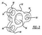
図3及び4を参照して、アダプタ50について詳細に説明する。アダプタ50は、テーパー状受入れ部(tapered receptacle)54を形成する本体52を含む。テーパー状受入れ部54は、本明細書において説明するようにアダプタ50によって各種インプラントを骨増生体10に結合するための結合部材を与える。本体52から、第一締結具用フランジ56、第二締結具用フランジ58及び第三締結具フランジ60が延びる。第一締結具用フランジ56は、第一開口部62を形成し、第二締結具用フランジ58は第二開口部64を形成し、第三締結具用フランジ60は第三開口部66を形成する。第一、第二及び第三締結具用フランジ56、58及び60は、本体52の周りに、例えば、アダプタ境界面14の第一、第二及び第三アダプタ保持孔34、36及び38の設置場所に対応するように任意の適切な位置に離間して配置される。第一、第二及び第三開口部62、64及び66は、締結具が第一、第二又は第三アダプタ保持孔34、36及び38の1つに受け入れられて、アダプタ50を骨増生体10に固定できるように、各々、孔を貫通する適切な締結具を受け入れるようなサイズを持ち、そのように配列される。 The
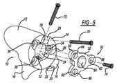
更に図5及び6において、埋込部位において骨増生体10を骨に固定するように構成された第一骨締結具70及び第二骨締結具72を示す。細長い骨ネジなどの適切な締結器具を使用できる。第一骨締結具70は、第一骨ネジ孔30に受け入れられ、これを貫通するように構成される。第二骨締結具72は、第二骨ネジ孔32に受け入れられこれを貫通するように構成される。 5 and 6, there is shown a
第一及び第二骨ネジ孔30及び32は、第一及び第二骨締結具70及び72を埋込部位における所望の設置場所へ向けるように適切に位置付けて、傾斜させることができる。例えば、第一及び第二骨ネジ孔30及び32は、埋込部位における骨増生体10の保持を最大化するために、埋込部位における締結具70及び72の骨への保持を最大化する向きにできる。例えば、第一及び第二骨ネジ孔30及び32は、患者の欠損部位において骨増生体10を固定するために第一及び第二締結具70及び72を患者の解剖学的構造に基づく最適の位置へ向けるように、患者固有の向き及び位置を持つことができる。アダプタ50は、任意の適切な生体適合性金属などの任意の適切な材料で製造できる。 The first and second bone screw holes 30 and 32 can be properly positioned and angled to direct the first and
アダプタ50は、第一挿入締結具74がアダプタ50の第一開口部62を通過して第一アダプタ保持孔34の中まで延びることによって、アダプタ境界面14において固定される。同様に、第二挿入締結具76は、第二開口部64を通過して第二アダプタ保持孔36の中まで挿入され、第三挿入締結具78は、第三開口部66を通過して第三アダプタ保持孔38の中まで挿入される。 The
アダプタ50は、患者の解剖学的構造に厳密に合致する患者固有のサイズ及び形状を備えることができる骨増生体10と異なり、多様な標準サイズ(stock size)で提供できる。例えば、アダプタ50は、小、中、大サイズで提供でき、骨増生体10の患者固有のサイズに基づいてサイズを選択できる。従って、アダプタ50は、本明細書において説明するように、関節窩球(glenosphere)など任意の適切なサイズのストックインプラントを、患者固有の骨増生体10のサイズ及び形状に関係なく骨増生体に結合できるようにする。 The
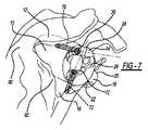
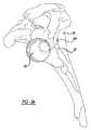
骨増生体10は、任意の適切な骨欠損部位に埋め込める。例えば、図7及び8を参照すると、骨増生体10は、関節窩92の欠損部を充填するために肩甲骨に埋め込める。骨係合面12は、関節窩92の中まで延び、第一及び第二フランジ16及び18は関節窩92に近接する肩甲骨90の部分に重なって、骨増生体10の回転を制限する。第一及び第二骨締結具70及び72は、それぞれ第一及び第二骨ネジ孔30及び32を通過して、肩甲骨90の中まで延びて、骨増生体10を肩甲骨90に固定する。図8に示すように、アダプタ50は、アダプタ境界面14において骨増生体10に結合され、インプラントをアダプタ50によって骨増生体10に結合するためにインプラントのための結合部材を提供する。結合部材は、アダプタ50のテーパー状受入れ部54によって与えられる。骨増生体10とアダプタ50は、患者固有の(即ち特別仕様)骨増生体10及び標準アダプタ50を含めて、一緒に、骨欠損を持つ埋込部位にインプラントを結合するために適するインプラント組立体を提供する。 The
図9を参照すると、関節部材102は、アダプタ50に結合できるので、インプラント組立体の一部として含めることができる。より具体的には、関節部材102は、凸状関節面104と柄部(stem)106とを含む。柄部106は、柄部106がテーパー状受入れ部54内に挿入されたとき例えば柄部106とテーパー状受入れ部54との間のモールステーパー接続(Morse taper connection)によって柄部106をアダプタ50に結合できるように、テーパー状であり、かつアダプタ60のテーパー状受入れ部54に対応する。関節部材102は、アダプタ50による関節部材102の骨増生体10への接続が、骨増生体10が関節窩92に埋め込まれたとき逆肩関節インプラント組立体を与えるように、肩関節インプラントの関節窩球などの任意の適切な関節部材とすることができる。柄部106は、関節部材102と一体的又は一枚岩的であるか、又は関節部材102とアダプタ50(Biomet(インディアナ州ワルシャウ)社のVersa-Dial(商標)アダプタなど)との間の中間部材の柄部である。関節部材102が結合された骨増生体10は、上腕骨においても結合できる。関節部材102は、適切な金属または重合体材料などの任意の適切な生体適合性材料で製造できる。 Referring to FIG. 9, the articulating
更に図10を参照すると、一次的肩関節インプラント組立体の場合、ベースプレート110をアダプタ50に結合できる。ベースプレート110は、ベースプレート柄部112とこれに対向する平面表面114とを含む。ベースプレート柄部112は、アダプタ50のテーパー状受入れ部54内に着座して、ベースプレート110を例えばモールステーパーによってアダプタ50に接続する。平面表面114にベアリング116が結合され、ベアリングは、凹状関節面118を含む。ベアリング116は、重合体材料などの任意の適切な材料で製造できる。ベアリング116は、ベースプレート110の平面表面114から延びるフランジ120とベアリング116との間の相互作用によってなど、任意の適切な様式で平面表面114に結合できる。フランジ120は、フランジ120とベアリング116の凹部又は刻み目との間の相互作用よるなど任意の適切な様式でベアリング116を平面表面114に結合できる。ベアリング116は、患者の上腕骨に結合された関節部材102などの適切な関節部材と関節式に接続され、それによって、一次的肩関節インプラントを与えることができる。インプラントにおいて、ベアリング116は、関節窩92において従って一次的肩関節インプラントにおいて関節窩関節面を与える。ベースプレート110及びベアリング116が結合された骨増生体10は、逆肩関節インプラントのために患者の上腕骨に埋め込むこともできる。 Still referring to FIG. 10, in the case of a primary shoulder joint implant assembly, the
図11において、本教示に従った別の骨増生体を参照番号150で示す。骨増生体150は、概略的に、骨係合面152とアダプタ境界面154とを含む。骨係合面152は、概略的にアダプタ境界面154に対向する。骨係合面152は、これから延びる第一フランジ156と第二フランジ158とを含む。骨増生体10の骨係合面12と同様、骨増生体150の骨係合面152は、具体的患者の骨欠損部に着座しこれを充填するサイズ及び形状を持つ患者固有の表面を持つことができる。第一フランジ156及び第二フランジ158は、任意の適切な場所において患者の骨欠損部に係合して欠損部において骨を置き換えかつ骨増生体150の回転を制限する向き及び形状を持つことができる。 In FIG. 11, another bone augmentation organism in accordance with the present teachings is indicated at
骨増生体150のほぼ中心において、骨増生体150によって中央孔又は第一骨ネジ孔160が形成される。骨増生体150は、更に、第二骨ネジ孔162、第三骨ネジ孔164及び第四骨ネジ孔166を含む。第一、第二、第三及び第四骨ネジ孔160〜166は、骨増生体150の任意の適切な場所に配置でき、かつ本明細書において詳細に説明するように、骨欠損部において骨増生体150を固定して欠損した骨を置き換えるために、孔を貫通する骨ネジなどの締結具を骨欠損部において骨の中へ向けるように任意の適切な角度を向くことができる。従って、第一、第二、第三及び第四骨ネジ孔160〜166は、締結具を患者の健康な骨の中へ向けるために特別仕様の向きを持つことができる。 A central bore or first bone screw bore 160 is formed by the bone augment 150 at approximately the center of the bone augment 150. The bone augment 150 further includes a second
骨増生体150は、更にアダプタ用凹部170を含み、凹部は第一骨ネジ孔160を取り囲む。アダプタ用凹部170は、概略的に、アダプタ境界面154の凹状部分であり、下で更に説明するように図12に示すアダプタ180を受け入れるように構成される。第一骨ネジ孔160は、アダプタ用凹部170から骨係合面152まで延びる。第二骨ネジ孔162も、アダプタ用凹部170から骨増生体150を通過して骨係合面152まで延びる。第三及び第四骨ネジ孔164及び166は、アダプタ用凹部170から離間して、アダプタ境界面154から骨増生体150を通過して骨係合面152まで延びる。又は、第一、第二、第三及び第四骨ネジ孔160〜166は、骨増生体150の任意の適切な場所に配列でき、かつ、本明細書において説明するように骨ネジを骨の所望の場所へ向けるように任意の適切な角度を向くことができる。 The bone augment 150 further includes an
骨増生体150は、更に、第一、第二及び第三アダプタ保持孔172、174及び176を含む。第一、第二及び第三アダプタ保持孔172、174及び176は、骨係合面152の任意の場所において離間でき、本明細書において更に説明するように、アダプタ180を骨増生体150のアダプタ境界面154に保持するために任意の適切な締結具を受け入れるように構成される。 The bone augment 150 further includes first, second and third
図12を参照すると、アダプタ180は、概略的に、本体182と、第一表面184と、第一表面184の反対側の第二表面186とを含む。第一及び第二表面184及び186は、概ね平面的である。アダプタ180は、テーパー状受入れ部188を形成する。テーパー状受入れ部188の開口部は、第一表面184に形成される。テーパー状受入れ部188は、本体182を貫通して、第二表面186から延びる。テーパー状受入れ部188は、その直径が第一表面において最大であるようにテーパー状であり、テーパー状受入れ部188が第二表面186から延びるとき直径は徐々に小さくなる。テーパー状受入れ部188の直径は、第二表面186から最も遠いテーパー状受入れ部188の部分において最も小さい。アダプタ180は、更に第一開口部190、第二開口部192及び第三開口部194を含む。第一、第二及び第三開口部190、192及び194の各々は本体182によって形成され、各々、アダプタ180を骨増生体150に結合するために開口部を貫通する適切な締結具を受け入れるために、本体182の第一表面184と第二表面186との間に延びる。従って、第一、第二及び第三開口部190、192及び194は、第一、第二及び第三アダプタ保持孔172、174及び176と整列するように配列される。アダプタ50と同様、アダプタ180は、小、中、大など、骨増生体150と協働する多様な標準ストックサイズ及び形状で提供できる。従って、アダプタ180は、関節部材102又はベースプレート110などの任意の適切な標準化又は患者固有のインプラントを患者固有の骨増生体150に結合できる。 Referring to FIG. 12, the
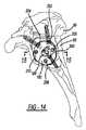
更に図13及び14を参照すると、骨増生体150は、関節窩92の欠損部を充填するために肩甲骨90に埋め込むなど、骨の欠損部を充填するために任意の適切な骨に埋め込める。具体的には、第一骨ネジ198は、骨増生体150の第一骨ネジ孔160を通過して関節窩92の中へ挿入されて、骨増生体150を関節窩92に固定する。同様に、第二骨ネジ200は第二骨ネジ孔162を通過して挿入され、第三骨ネジ202は第三骨ネジ孔164を通過して挿入され、第四骨ネジ204は第四骨ネジ孔166を通過して挿入される。第一、第二、第三及び第四骨ネジ孔160〜166は、関節窩92において骨増生体150を最大限に保持するために、第一、第二、第三及び第四骨ネジ198〜204の各々を患者の特定の骨欠損部に従って肩甲骨90における所望の位置へ向けるように位置付けかつ角度を持たせる。 With further reference to FIGS. 13 and 14, the bone augment 150 may be embedded in any suitable bone for filling a bone defect, such as being implanted in the
アダプタ180は、図14に示すように、アダプタ境界面154に当接して着座し、第一開口部190を通過して第一アダプタ保持孔172の中まで延びる第一アダプタスクリュー206、第二開口部192を通過して第二アダプタ保持孔174の中へ延びる第二アダプタスクリュー208及び第三開口部194を通過して第三アダプタ保持孔176の中まで延びる第三アダプタスクリュー210によってアダプタ境界面に固定される。 The
図15を参照すると、アダプタ180は、第二表面186から延びる概ね正方形のフランジ212を含む。フランジは、概ねテーパー状受入れ部188を取り囲み、かつ受入れ部188に対向する。正方形フランジ212は、概ね正方形の側壁214(例えば、図11)を含むアダプタ用凹部170と相補的なサイズ及び形状を持つ。アダプタ180は、正方形フランジ212がアダプタ用凹部170内に着座してその正方形側壁214に当接するように、アダプタ境界面154に当接して着座する。正方形フランジ212とアダプタ用凹部170との間の相互作用は、骨増生体150に対するアダプタ180の回転を制限するのを助ける。アダプタ用凹部170及びフランジ212は正方形として図示するが、他の任意の適切な形状を持つことができる。 Referring to FIG. 15,
アダプタ180を用いて任意の適切なインプラントを骨増生体150に結合できる。例えば、関節部材102は、関節部材102の柄部106を挿入してテーパー状受入れ部188と協働させることによって、テーパーロックなどによって、アダプタ180に接続できる。関節部材102をアダプタ180に結合すると、逆肩関節形成術のためのインプラント組立体が提供される。更に、ベアリング116が結合されたベースプレート110を(図10)アダプタ180に結合して、一次的肩関節形成のためのインプラント組立体を提供できる。この組立体において、凸状関節面118は、関節窩92に設置され、関節部材102は、上腕骨に取り付けられる。ベアリング116は、上腕骨の生来の上腕骨頭とも関節式に接続できる。
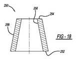
更に図16〜18において、本教示に従った別の骨増生体を参照番号250で示す。骨増生体250は、概略的に第一端部252と、第一端部252の反対側の第二端部254とを含む。骨増生体250は、更に第一端部252と第二端部254との間に延在する骨係合面256を含む。骨係合面256に対向して結合面258がある。骨増生体250は、概ね円錐形スリーブの形状を持つ。従って、骨係合面256は、概ね円錐形であり、第一端部252から第二端部254へ内向きにテーパー状である。骨係合面256は、第一端部252においてその最大直径を有し、第二端部254においてその最小直径を有する。骨係合面256は円滑であるか、又はその中への骨の成長を容易にする多孔質表面260とすることができる。 Further, in FIGS. 16-18, another bone augmentation body in accordance with the present teachings is indicated at
結合面258も第一端部252から第二端部254へ内向きにテーパー状である。従って、結合面258は、第一端部252においてその最大直径を有し、第二端部254においてその最小直径を有する。結合面258は、概略的に、第一端部252から第二端部254まで骨増生体250を貫通する内側孔262を形成する。骨増生体250は、複数の異なるストックサイズ又は形状など、任意の適切なサイズ又は形状を持つことができる。例えば、骨増生体250は、標準的小、中、大サイズを持つことができる。結合面258は、ネジ切りでき、図示するようにテーパー状にする必要はなく、直線的に延びることができる。 Coupling
骨増生体250は、適切な生体適合性金属材料又は適切な生体適合性重合体材料などの任意の適切な材料で製造できる。骨増生体250は、適切な成形技術又は3Dプリントなど適切な付加製造技術などの任意の適切な製造工程又は技術を用いて製造できる。 The bone augment 250 can be made of any suitable material, such as a suitable biocompatible metallic material or a suitable biocompatible polymeric material. The bone augment 250 can be manufactured using any suitable manufacturing process or technique, such as suitable molding techniques or suitable additive manufacturing techniques such as 3D printing.
更に図19において、本教示に従った別の骨増生体を、参照番号270で示す。骨増生体270は、第一端部272と、第一端部272の反対側の第二端部274とを含む。骨係合面276は、骨増生体270の外側部に在り、第一端部272と第二端部274との間に延在する。骨係合面276に対向して結合面278があり、結合面は骨増生体270の内側孔280を形成する。結合面278は、ネジ切りでき、図に示すようにテーパー状にする必要はなく、直線的に延びることができる。骨係合面276及び結合面は、両方とも第一端部272から第二端部274へ内向きにテーパー状である。従って、骨増生体270は、第一端部272においてその最大直径を持ち、第二端部においてその最小直径を持つようなサイズを持つ。従って、内側孔280も第一端部272から第二端部274へテーパー状である。骨係合面276から雄ネジ部282が延在し、それによって、骨増生体270を骨の中へねじ入れて、骨増生体270を埋め込める。 Further in FIG. 19, another bone augmentation body in accordance with the present teachings is indicated by
本教示に従った別の骨増生体を、参照番号290で示す(図20)。骨増生体290は、概略的に、第一端部292と第二端部294とを含む。骨係合面296は、結合面298と同様に第一端部292から第二端部294まで延在する。骨係合面296及び結合面298の両方は、概略的に第一端部292から第二端部294へ内向きにテーパー状であって、円錐形スリーブを持つ骨増生体290を与える。結合面298は、第一端部292から第二端部294へ延びる内側孔302を形成する。結合面298は、ネジ切りでき、図示するようにテーパー状にする必要はなく、直線的に延びることができる。骨係合面296は、円滑とするか、又は骨欠損部位において骨増生体290を固定するためにその中への骨の成長を容易にする多孔質表面300を含むことができる。 Another bone augmenter in accordance with the present teachings is indicated by reference numeral 290 (FIG. 20). The bone augment 290 generally includes a
骨欠損部位において骨増生体290を更に固定するために、骨増生体290は、内側孔302の両側から延びる第一フランジ304と第二フランジ306とを含む。第一フランジ304及び第二フランジ306は、各々、骨係合面296及び多孔質表面300を含む。第一フランジ304は、第一孔308を形成し、第二フランジ306は第二孔310を形成する。第一孔308及び第二孔310は、埋込部位における骨増生体290の保持を強化し、骨増生体290の回転を防止する又は単純に骨増生体290の固定を確実にするために、孔を通過する適切な締結具を受け入れるように構成される。骨増生体290は、骨欠損部位において任意の適切な位置を向くことができる。例えば、第一及び第二フランジ304及び306は、例えば関節窩を横切ってすぐ上及びすぐ下に延びる線に沿って整列するように位置づけできる。第一及び第二フランジ304及び306を図に示すが、骨増生体290は、任意の適切な向きで配列された任意の適切な数のフランジを備えることができる。 To further secure the bone augment 290 at the bone defect site, the bone augment 290 includes a
更に図21〜23において、本教示に従った別の骨増生体を参照番号230で示す。骨増生体320は、概略的に第一端部322とその反対側の第二端部324とを含む。骨係合面326は、第一端部322と第二端部324との間に延在し、結合面328に対向する。結合面328は、第一端部322から第二端部324へ内向きに概ねテーパー状である。骨係合面326は、その中への骨成長を容易にするために多孔質表面330で被覆される。結合面はネジ切りすることができ、図示するようにテーパー状にする必要はなく、直線的に延びることができる。 Still in FIGS. 21-23, another bone augmentation body in accordance with the present teachings is indicated by reference numeral 230. The bone augment 320 generally includes a
フランジ332は、骨係合面326から延びて、骨係合面326の周りに約180度延在する。フランジ332は、外側表面と内側表面336とを含み、内側表面は骨係合面326に当接してこれに固定される。内側表面336は、骨係合面326と一体とすることもできる。フランジ332は、第一端部338と、これに対向する第二端部とを含む。フランジ332の外側表面334は自身の骨係合面342を含み、この骨係合面は、円滑でも、多孔質表面330を含んでもよい。 The
骨増生体320は、金属または重合体材料などの任意の適切な生体適合性材料で製造できる。フランジ332は、成形工程又は付加製造などによって、骨増生体320の残り部分と一体的に形成できる。フランジ332は、骨増生体320の残り部分と別個に形成して、任意の適切な様式で第一端部322と第二端部324との間で骨係合面326に取り付けることもできる。フランジ332は、埋込部位における特定の骨欠損部を充填するために骨係合面326の周りに任意の適切な距離だけ延在できる。フランジ332は、例えば図24に示すように結合面328を完全に取り囲む円形フランジとすることもできる。 The bone augment 320 can be made of any suitable biocompatible material, such as a metal or polymeric material. The
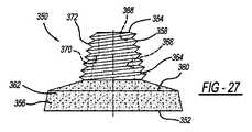
図25〜27において、本教示に従ったアダプタ又はベースプレートを参照番号350で示す。本明細書において説明するように、ベースプレートは、骨欠損部を持つ埋込部位において適切なインプラントを固定するために骨増生体250、270、290、320のいずれにも結合できる。ベースプレート350は、骨の損失が僅かである場合などには、骨に直接固定することもできる。 In Figures 25-27, an adapter or base plate in accordance with the present teachings is indicated by
ベースプレートは、第一端部352と、第一端部352の反対側の第二端部354とを含む。第一端部352には土台部356があり、第二端部354には柄部358がある。土台部356と柄部358との間には中間部分360があり、中間部分は、土台部356から柄部358へテーパー状とすることができる。土台部356は、その中への骨の成長を容易にして、埋込部位におけるベースプレート350の保持を強化するために、多孔質外面362を含むことができる。 The base plate includes a
柄部358は、テーパー状外面又は結合面364と、テーパー状内面366とを含む。テーパー状内面366は、第一端部352から柄部358のほぼ中間点まで延在する。テーパー状内面366は、第一端部352から柄部358へ内向きにテーパー状であり、テーパー状内面366は、締結具用孔368と一体的である。締結具用孔368は、柄部358によって形成され、テーパー状内面366から柄部358の第二端部354まで延びる。 The
ステップ370が、テーパー状内面366が締結具用孔368へ移行する場所に形成される。ステップ370は、例えば、本明細書において更に説明するように、締結具を柄部358内に保持するために締結具の頭を着座できる表面を与える。ステップ370は、締結具用孔368へ向けて内向きにテーパー状とすることができる。図27に示すように、柄部358は、テーパー状外面364にネジ部372を持つことができる。ネジ部372は、直接骨の中へのベースプレート350の埋込み、又は柄部358と骨増生体250の結合面258又は本明細書において説明する結合面(そのいずれかが雌ネジ部を含むことができる)278、298又は328のいずれかとの間の協働を容易にする。 Step 370 is formed where the tapered
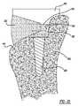
図28を参照すると、骨増生体250は、肩甲骨90において関節窩92に存在する欠損部などの骨欠損部を充填するために任意の適切な場所に埋め込める。骨増生体250は、任意の適切な様式でかつ任意の適切な道具を用いて埋め込める。例えば、骨増生体は、詰込み(impaction)によって埋め込める。本明細書において説明する他の骨増生体のいずれも、任意の適切な様式で埋め込める。例えば、骨増生体270は、骨増生体270を適切な埋込装置を用いて回転させることによって、骨増生体270の雄ネジ部282を関節窩92の中へネジ入れることによって埋め込める。第一及び第二フランジ304及び306を持つ骨増生体290は、骨増生体の回転を防止するために骨増生体の固定を増強することが適切又は望ましい骨欠損部位に埋め込める。埋込部位における骨の損失がもっと大きい場合、フランジ332が骨欠損部を充填するように骨増生体320を埋め込み、位置付けることができる。フランジ332は、骨欠損部を充填するために任意の適切なサイズ又は形状を持つことができる。更に大きい骨欠損部を充填するためには、フランジ332が骨増生体320の周り全体に延在する図24の骨増生体320を使用できる。 Referring to FIG. 28, the
骨増生体250、270、290又は320のいずれかを埋め込んだ後、図29に示すようにベースプレート350を骨増生体に結合できる。ベースプレート350は、例えば、図30に示すようにテーパー状外面364がベースプレート350のテーパー状内面366に当接してベースプレート350をテーパーロックによって骨増生体250に結合するように、ベースプレート350の柄部358を骨増生体250の内側孔362へ挿入することによって、骨増生体250に結合される。ベースプレート350を骨増生体250及び例えば関節窩92に更に固定するために、骨ネジ380の頭382がステップ370に着座してネジ部384が肩甲骨90の中まで延びるように、骨ネジ380をベースプレート350の締結具用孔368へ挿入できる。 After implanting any of the bone augments 250, 270, 290 or 320, the
図31及び32を参照すると、ベースプレート350は、任意の適切なインプラントをベースプレート350に結合するための結合部材を与えることができる。例えば、図31に示すように、関節部材102を、関節部材102の柄部106とベースプレート350のテーパー状内面366との相互作用によってベースプレート350に接続できる。例えば、柄部106は、モールステーパーフィットによってテーパー状内面366に結合できる。 With reference to FIGS. 31 and 32,
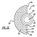
図32を参照すると、ベースプレート350は、土台部356から延びるフランジの形の結合部材394によるなど任意の適切な様式でベースプレート350の土台部356に結合されたベアリング390を含むことができる。ベアリング390は、例えば関節部材102と関節式に接続するように構成された凹状関節面392を含むことができる。関節部材は、上腕骨に取り付けることができる。このようにして、骨増生体250及びベアリング390は、一次的肩関節プラントのためのインプラント組立体を与える。 Referring to FIG. 32, the
本教示は、ほぼどのような場所においても任意の骨欠損部を充填するために適合化できる。例えば、図33を参照すると、糜爛した関節面404を持つ一般的骨402は、フランジ332が糜爛した関節面404から失われた骨に代わるように、骨に結合された骨増生体320を含むことができる。骨増生体320は、ベースプレート350のための取付け台を提供できる。具体的には、ベースプレート350の柄部358は、テーパー状外面364が結合面328と噛み合ってその間にモールステーパー結合を形成するように、骨増生体320内へ挿入できる。固定を強化するために、骨ネジ406が柄部358の締結具用孔368を通過して骨増生体320の内側表面336を通過して骨402の中まで延びるように、骨ネジ406をベースプレート350内へ挿入できる。骨ネジ406を締めるとき、ベースプレート350及び骨増生体320は、骨402に押し付けられる。骨ネジ406の使用は、骨増生体320及びベースプレート350の骨402への固定を強化し、欠損部位における治癒を容易にする。 The present teachings can be adapted to fill any bone defect at almost any location. For example, referring to FIG. 33, a common bone 402 with a scooped articulating
図34を参照すると、関節部材102などのインプラント構成要素は、直接、骨増生体250に接続できるので、ベースプレート350を不要にする。例えば、柄部106は、関節部材102の柄部106と骨増生体250の結合面258との間のモールステーパーフィットによって結合面258に接続できる。 Referring to FIG. 34, implant components such as the articulating
本明細書において説明する骨増生体及びアダプタは、セットまたはキットとして提供できる。例えば、キットは、骨増生体10、150、250、270、290及び320の1つ又はそれ以上並びにアダプタ50、180又は250の1つ又はそれ以上を含むことができる。骨増生体10、150、250、270、290及び320は、様々な標準サイズ及び形状を持つことができる。又は上述のように、骨増生体10、150、250、270、290及び320は、患者固有とすることができる。アダプタ50、180及び250は、キットに含まれる特定の骨増生体10、150、250、270、290及び320と結合できるように、小、中、大などの標準サイズで提供できる。 The bone augments and adapters described herein can be provided as a set or kit. For example, the kit can include one or more of
実施形態の以上の説明は、例示及び説明のために示す。以上の説明は網羅的ではなく開示を限定することを意図しない。特定の実施形態の個別の要素又は特徴は、特定の実施形態に限定されず、適用される場合には、具体的に図示又は説明されない場合でも交換可能であり、選択された実施形態に使用できる。実施形態は、多様に変更できる。このような変更は、開示からの逸脱とはみなされず、これらの全ての修正は、開示の範囲に含まれるものである。 The foregoing description of the embodiments is presented for purposes of illustration and description. The above description is not exhaustive and is not intended to limit the disclosure. The individual elements or features of a particular embodiment are not limited to a particular embodiment, and, if applicable, may be interchanged even if not specifically illustrated or described, and may be used in selected embodiments. . The embodiments can be varied in many ways. Such changes are not considered to be a departure from the disclosure, and all such modifications are intended to be included within the scope of the disclosure.
Claims (8)
Translated fromJapanese本体と、前記本体から延びている複数のフランジとを有するアダプタであって、前記複数のフランジの各々は、前記アダプタ用凹部によって形成されている開口部に対応する開口部を形成しており、前記アダプタが前記アダプタ用凹部に嵌合するようなサイズである、アダプタと、
前記アダプタと結合するように構成された関節部材と、
を備えるインプラント組立体。A bone engaging surface that is patient specific and is a negative structure of the anatomic structure at the implant site of the bone augment, configured to receive a fastener for securing the bone augment at the implant site A bone augmenting body comprising a bone engaging surfacecomprising at least one bone screw hole and a coupling surface forming a recess for the adapter;
An adapter having a body and a plurality of flanges extending from the body, each of the plurality of flanges forming an opening corresponding to the opening formed by the recess for the adapter, An adapter that is sized such that the adapter fits in the recess for the adapter;
An articulation member configured to couple with the adapter;
Implant assembly comprising:
前記アダプタが複数の様々な標準サイズの1つであることを特徴とする、請求項1に記載のインプラント組立体。The adapter includes a base, a tapered handle, a tapered inner surface, and a fastener hole;
The implant assembly according to claim 1, wherein the adapter is one of a plurality of different standard sizes.
前記アダプタ境界面において前記骨増生体に接続しかつ前記アダプタ用凹部内で当接するように構成されたアダプタであって、該アダプタが複数のフランジと結合部材を含み、前記複数のフランジの各々は、前記アダプタが前記骨増生体に据え付けられた時に前記骨増生体の上面と面一である前記アダプタの本体から延びているフランジ表面を有する、アダプタと、
前記結合部材において前記アダプタと結合するように構成された関節部材と、を備えるインプラント組立体。A bone engaging surface that is patient specific and is a negative structure of the anatomic structure at the implant site of the bone augment, configured to receive a fastener for securing the bone augment at the implant site A bone augmenting body comprising a bone engaging surfacecomprising at least one bone screw hole, and an adapter interface forming a recess for the adapter;
An adapter configured to connect to the bone augment at the adapter interface and abut within the adapter recess, the adapter including a plurality of flanges and a coupling member, each of the plurality of flanges being An adapter having a flange surface extending from a body of the adapter which is flush with a top surface of the bone augmentation body when the adapter is installed in the bone augmentation body;
An articulating member configured to couple with the adapter at the connecting member.
Applications Claiming Priority (5)
| Application Number | Priority Date | Filing Date | Title |
|---|---|---|---|
| US201361775119P | 2013-03-08 | 2013-03-08 | |
| US61/775,119 | 2013-03-08 | ||
| US14/028,930US9668873B2 (en) | 2013-03-08 | 2013-09-17 | Modular glenoid base plate with augments |
| US14/028,930 | 2013-09-17 | ||
| PCT/US2014/021281WO2014138424A1 (en) | 2013-03-08 | 2014-03-06 | Modular glenoid base plate with augments |
Publications (3)
| Publication Number | Publication Date |
|---|---|
| JP2016513498A JP2016513498A (en) | 2016-05-16 |
| JP2016513498A5 JP2016513498A5 (en) | 2017-04-06 |
| JP6506181B2true JP6506181B2 (en) | 2019-04-24 |
Family
ID=51488807
Family Applications (1)
| Application Number | Title | Priority Date | Filing Date |
|---|---|---|---|
| JP2015561663AActiveJP6506181B2 (en) | 2013-03-08 | 2014-03-06 | Modular glenoid base plate with augmentation |
Country Status (6)
| Country | Link |
|---|---|
| US (2) | US9668873B2 (en) |
| EP (2) | EP2964157B1 (en) |
| JP (1) | JP6506181B2 (en) |
| AU (1) | AU2014225636B2 (en) |
| CA (1) | CA2904029C (en) |
| WO (1) | WO2014138424A1 (en) |
Cited By (1)
| Publication number | Priority date | Publication date | Assignee | Title |
|---|---|---|---|---|
| KR20220063831A (en)* | 2020-11-10 | 2022-05-18 | 주식회사 코렌텍 | Modular Augment |
Families Citing this family (74)
| Publication number | Priority date | Publication date | Assignee | Title |
|---|---|---|---|---|
| US8303665B2 (en) | 2004-06-15 | 2012-11-06 | Tornier Sas | Glenoidal component, set of such components and shoulder prosthesis incorporating such a glenoidal component |
| US8778028B2 (en) | 2005-02-25 | 2014-07-15 | Shoulder Innovations, Inc. | Methods and devices for less invasive glenoid replacement |
| US20230080207A1 (en) | 2005-02-25 | 2023-03-16 | Shoulder Innovations, Inc. | Methods and devices for less invasive glenoid replacement |
| FR2932674B1 (en) | 2008-06-20 | 2011-11-18 | Tornier Sa | METHOD FOR MODELING A GLENOIDAL SURFACE OF AN OMOPLATE, DEVICE FOR IMPLANTING A GLENOIDAL COMPONENT OF A SHOULDER PROSTHESIS, AND METHOD FOR MANUFACTURING SUCH COMPOUND |
| FR2955247B1 (en) | 2010-01-21 | 2013-04-26 | Tornier Sa | GLENOIDAL COMPONENT OF SHOULDER PROSTHESIS |
| USD685474S1 (en) | 2010-07-06 | 2013-07-02 | Tornier, Inc. | Prosthesis anchor |
| FR2966343B1 (en) | 2010-10-22 | 2012-12-07 | Tornier Sa | SET OF GLENOIDIAN COMPONENTS OF SHOULDER PROSTHESIS |
| FR2971144A1 (en) | 2011-02-08 | 2012-08-10 | Tornier Sa | GLENOIDAL IMPLANT FOR SHOULDER PROSTHESIS AND SURGICAL KIT |
| FR2978912A1 (en) | 2011-08-10 | 2013-02-15 | Tornier Inc | ANCILLARY EXTRACTION OF A PROSTHESIS |
| EP2846716B8 (en)* | 2012-05-08 | 2018-01-10 | TriMed, Inc. | Implant for fixation of first and second bones |
| US9668873B2 (en) | 2013-03-08 | 2017-06-06 | Biomet Manufacturing, Llc | Modular glenoid base plate with augments |
| FR3010628B1 (en) | 2013-09-18 | 2015-10-16 | Medicrea International | METHOD FOR REALIZING THE IDEAL CURVATURE OF A ROD OF A VERTEBRAL OSTEOSYNTHESIS EQUIPMENT FOR STRENGTHENING THE VERTEBRAL COLUMN OF A PATIENT |
| EP3057524B1 (en) | 2013-10-10 | 2019-11-20 | Imascap | Method for designing and producing a shoulder surgery guide |
| FR3012030B1 (en) | 2013-10-18 | 2015-12-25 | Medicrea International | METHOD FOR REALIZING THE IDEAL CURVATURE OF A ROD OF A VERTEBRAL OSTEOSYNTHESIS EQUIPMENT FOR STRENGTHENING THE VERTEBRAL COLUMN OF A PATIENT |
| EP3925574A1 (en) | 2013-11-08 | 2021-12-22 | Imascap | Pre-operatively planned adaptive glenoid implants and method for planning its design |
| US10405993B2 (en) | 2013-11-13 | 2019-09-10 | Tornier Sas | Shoulder patient specific instrument |
| WO2015103090A1 (en) | 2014-01-03 | 2015-07-09 | Tornier, Inc. | Reverse shoulder systems |
| US12023253B2 (en)* | 2014-01-24 | 2024-07-02 | Howmedica Osteonics Corp. | Humeral implant anchor system |
| US10456264B2 (en)* | 2014-01-24 | 2019-10-29 | Tornier, Inc. | Humeral implant anchor system |
| US10492926B1 (en) | 2014-09-04 | 2019-12-03 | Shoulder Innovations, Inc. | Alignment guide for humeral or femoral stem replacement prostheses |
| EP3053547B1 (en)* | 2015-02-04 | 2017-07-19 | Alessandro Melozzi | Improved hip prosthesis |
| CA2983650C (en) | 2015-04-24 | 2021-03-16 | Biomet Manufacturing, Llc | Patient-specific augmented glenoid systems and methods |
| US10722374B2 (en) | 2015-05-05 | 2020-07-28 | Tornier, Inc. | Convertible glenoid implant |
| US10456211B2 (en) | 2015-11-04 | 2019-10-29 | Medicrea International | Methods and apparatus for spinal reconstructive surgery and measuring spinal length and intervertebral spacing, tension and rotation |
| EP3389513A1 (en) | 2015-12-16 | 2018-10-24 | Tornier, Inc. | Patient specific instruments and methods for joint prosthesis |
| US11090161B2 (en) | 2016-03-25 | 2021-08-17 | Howmedica Osteonics Corp. | Surgical instrumentation assembly, set and surgical shoulder repair method |
| EP3685804A1 (en)* | 2016-03-25 | 2020-07-29 | Tornier | Joint prosthesis spacer |
| US10463499B2 (en) | 2016-03-25 | 2019-11-05 | Tornier, Inc. | Stemless shoulder implant with fixation components |
| EP3260087B1 (en) | 2016-06-24 | 2019-08-07 | Tornier | Set for a glenoid implant |
| AU2017297403B2 (en)* | 2016-07-15 | 2022-04-21 | DJO Global, Inc. | Glenosphere with flange for augmented fixation and related methods |
| US10835383B2 (en) | 2016-07-15 | 2020-11-17 | Encore Medical, L.P. | Glenosphere with flange for augmented fixation and related methods |
| US11129724B2 (en) | 2016-07-28 | 2021-09-28 | Howmedica Osteonics Corp. | Stemless prosthesis anchor component |
| WO2018109556A1 (en) | 2016-12-12 | 2018-06-21 | Medicrea International | Systems and methods for patient-specific spinal implants |
| KR20250080917A (en) | 2017-01-19 | 2025-06-05 | 앙코르 메디컬, 엘.피.(디/비/에이 디제이오 서지컬) | Shoulder implant components |
| CA3051099C (en) | 2017-01-20 | 2022-07-12 | Biomet Manufacturing, Llc | Modular augment component |
| IT201700041420A1 (en)* | 2017-04-13 | 2018-10-13 | Limacorporate Spa | Scapular anchorage for the attachment of a glenoid component of a shoulder joint prosthesis to a scapula with impaired anatomy, and relative method of making said scapular anchorage |
| EP4520302A3 (en) | 2017-04-14 | 2025-04-16 | Shoulder Innovations, Inc. | Total shoulder prosthesis having inset glenoid implant convertible from anatomic to reverse |
| EP3612122B1 (en) | 2017-04-21 | 2023-12-20 | Medicrea International | A system for developing one or more patient-specific spinal implants |
| EP3644906B1 (en)* | 2017-06-29 | 2022-02-23 | Encore Medical, L.P. (D/B/A DJO Surgical) | Glenosphere with inserts for augmented fixation |
| US10959742B2 (en) | 2017-07-11 | 2021-03-30 | Tornier, Inc. | Patient specific humeral cutting guides |
| EP3651664A1 (en) | 2017-07-11 | 2020-05-20 | Tornier, Inc. | Guides and instruments for improving accuracy of glenoid implant placement |
| CA3072342A1 (en)* | 2017-08-10 | 2019-02-14 | Tornier, Inc. | Patient specific glenoid bone augment components and methods of making and using the same |
| MX2020003194A (en) | 2017-09-25 | 2020-12-09 | Howmedica Osteonics Corp | Patient specific stemless prosthesis anchor components. |
| WO2019079104A2 (en) | 2017-10-16 | 2019-04-25 | Imascap Sas | Shoulder implants and methods of use and assembly |
| US10918422B2 (en) | 2017-12-01 | 2021-02-16 | Medicrea International | Method and apparatus for inhibiting proximal junctional failure |
| US11399948B2 (en) | 2017-12-11 | 2022-08-02 | Howmedica Osteonics Corp. | Stemless prosthesis anchor components and kits |
| CA3087066A1 (en) | 2017-12-29 | 2019-07-04 | Tornier, Inc. | Patient specific humeral implant components |
| US12138172B2 (en) | 2018-04-30 | 2024-11-12 | Shoulder Innovations, Inc. | Inset/onlay glenoid, porous coated convertible glenoid, and humeral heads with textured undersides |
| US10813769B2 (en) | 2018-07-24 | 2020-10-27 | DePuy Synthes Products, Inc. | Baseplate of a modular shoulder joint prosthesis and related methods for implanting the same |
| EP4257090A3 (en) | 2018-10-02 | 2023-12-13 | Howmedica Osteonics Corp. | Shoulder prosthesis components and assemblies |
| EP3666228A1 (en)* | 2018-12-14 | 2020-06-17 | Howmedica Osteonics Corp. | Augmented, just-in-time, patient-specific implant manufacture |
| EP4406516A3 (en)* | 2019-01-28 | 2024-08-07 | Encore Medical, L.P. (D/B/A Djo Surgical) | Glenoid implant |
| AU2020237088B2 (en) | 2019-03-11 | 2025-09-04 | Shoulder Innovations, Inc. | Total reverse shoulder systems and methods |
| US11944385B2 (en) | 2019-04-02 | 2024-04-02 | Medicrea International | Systems and methods for medical image analysis |
| US11925417B2 (en) | 2019-04-02 | 2024-03-12 | Medicrea International | Systems, methods, and devices for developing patient-specific spinal implants, treatments, operations, and/or procedures |
| US11877801B2 (en) | 2019-04-02 | 2024-01-23 | Medicrea International | Systems, methods, and devices for developing patient-specific spinal implants, treatments, operations, and/or procedures |
| JP7257546B2 (en) | 2019-05-13 | 2023-04-13 | ハウメディカ オステオニクス コーポレイション | Glenoid baseplate and implant assembly |
| US11395741B2 (en) | 2019-05-16 | 2022-07-26 | Howmedica Osteonics Corp. | Joint replacement augments and associated instrumentation |
| US11887878B2 (en) | 2019-06-28 | 2024-01-30 | Applied Materials, Inc. | Detachable biasable electrostatic chuck for high temperature applications |
| USD893441S1 (en)* | 2019-06-28 | 2020-08-18 | Applied Materials, Inc. | Base plate for a processing chamber substrate support |
| AU2020204539B2 (en)* | 2019-07-12 | 2024-10-31 | Howmedica Osteonics Corp. | Augmented glenoid design |
| EP4003238A1 (en)* | 2019-07-24 | 2022-06-01 | Waldemar Link GmbH & Co. KG | Combination of graft and replacement piece for filling a bone defect |
| EP3982848A1 (en) | 2019-08-09 | 2022-04-20 | Howmedica Osteonics Corp. | Apparatuses and methods for implanting glenoid prostheses |
| EP4527357A3 (en) | 2019-10-01 | 2025-06-04 | Howmedica Osteonics Corporation | Shoulder prosthesis components and assemblies |
| USD951449S1 (en) | 2019-10-01 | 2022-05-10 | Howmedica Osteonics Corp. | Humeral implant |
| US11769251B2 (en) | 2019-12-26 | 2023-09-26 | Medicrea International | Systems and methods for medical image analysis |
| US11559402B2 (en) | 2020-02-04 | 2023-01-24 | Medos International Sarl | Soft glenoid awning and related repair procedures |
| WO2021202101A1 (en)* | 2020-04-01 | 2021-10-07 | Arthrex, Inc. | Systems and methods of forming orthopaedic implants including printed augments |
| AU2021202801A1 (en)* | 2020-05-07 | 2021-11-25 | Howmedica Osteonics Corp. | Stemless metaphyseal humeral implant |
| WO2022076504A1 (en)* | 2020-10-09 | 2022-04-14 | Arthrex, Inc. | Convertible orthopaedic implant systems and methods |
| USD947914S1 (en)* | 2020-11-23 | 2022-04-05 | Applied Materials, Inc. | Base plate for a processing chamber substrate support |
| US12318144B2 (en) | 2021-06-23 | 2025-06-03 | Medicrea International SA | Systems and methods for planning a patient-specific spinal correction |
| EP4147678B1 (en)* | 2021-09-10 | 2023-11-08 | Heraeus Medical GmbH | Augmentation device and augmentation system |
| EP4586968A1 (en) | 2022-09-14 | 2025-07-23 | ARCA By OrthoAgile, LLC | Glenoid replacement system and methods of implanting said glenoid replacement |
Family Cites Families (15)
| Publication number | Priority date | Publication date | Assignee | Title |
|---|---|---|---|---|
| US4524467A (en)* | 1983-11-21 | 1985-06-25 | Joint Medical Products Corp. | Apparatus for constraining a socket bearing in an artificial joint |
| US6783549B1 (en)* | 2001-07-27 | 2004-08-31 | Biomet, Inc. | Modular humeral head resurfacing system |
| US7854768B2 (en)* | 2006-01-20 | 2010-12-21 | Zimmer Technology, Inc. | Shoulder arthroplasty system |
| US7959680B2 (en)* | 2006-02-02 | 2011-06-14 | Biomet Manufacturing Corp. | Method and apparatus for performing a shoulder implant procedure |
| US7842093B2 (en)* | 2006-07-18 | 2010-11-30 | Biomet Manufacturing Corp. | Method and apparatus for a knee implant |
| EP2385810B1 (en)* | 2008-12-02 | 2018-07-18 | Smith & Nephew, Inc. | Iliac canal prosthesis |
| FR2944694B1 (en) | 2009-04-22 | 2012-05-18 | Tornier Sa | DEVICE FOR FIXING THE GLENE OF A GLENOIDAL ARTICULAR COMPONENT FOR A SHOULDER PROSTHESIS AND CORRESPONDING SHOULDER PROSTHESIS |
| WO2011044586A1 (en)* | 2009-10-10 | 2011-04-14 | Simplicity Orthopedics, Inc. | Method and apparatus for restoring a joint, including the provision and use of a longitudinally-adjustable and rotationally-adjustable joint prosthesis |
| US8444699B2 (en)* | 2010-02-18 | 2013-05-21 | Biomet Manufacturing Corp. | Method and apparatus for augmenting bone defects |
| US8480750B2 (en) | 2010-11-24 | 2013-07-09 | DePuy Synthes Products, LLC | Modular glenoid prosthesis |
| WO2012141790A1 (en)* | 2011-04-13 | 2012-10-18 | Synthes Usa, Llc | Patient specific joint prosthesis |
| US9554910B2 (en) | 2011-10-27 | 2017-01-31 | Biomet Manufacturing, Llc | Patient-specific glenoid guide and implants |
| US9439768B2 (en)* | 2011-12-08 | 2016-09-13 | Imds Llc | Glenoid vault fixation |
| CN104507910B (en) | 2012-07-30 | 2016-06-15 | 大正制药株式会社 | Partially saturated nitrogen-containing heterocyclic compounds |
| US9668873B2 (en) | 2013-03-08 | 2017-06-06 | Biomet Manufacturing, Llc | Modular glenoid base plate with augments |
- 2013
- 2013-09-17USUS14/028,930patent/US9668873B2/enactiveActive
- 2014
- 2014-03-06EPEP14712508.2Apatent/EP2964157B1/enactiveActive
- 2014-03-06EPEP18161808.3Apatent/EP3470021B1/enactiveActive
- 2014-03-06AUAU2014225636Apatent/AU2014225636B2/enactiveActive
- 2014-03-06JPJP2015561663Apatent/JP6506181B2/enactiveActive
- 2014-03-06CACA2904029Apatent/CA2904029C/enactiveActive
- 2014-03-06WOPCT/US2014/021281patent/WO2014138424A1/enactiveApplication Filing
- 2017
- 2017-02-16USUS15/434,244patent/US9925048B2/enactiveActive
Cited By (2)
| Publication number | Priority date | Publication date | Assignee | Title |
|---|---|---|---|---|
| KR20220063831A (en)* | 2020-11-10 | 2022-05-18 | 주식회사 코렌텍 | Modular Augment |
| KR102413389B1 (en) | 2020-11-10 | 2022-06-29 | 주식회사 코렌텍 | Modular Augment |
Also Published As
| Publication number | Publication date |
|---|---|
| WO2014138424A1 (en) | 2014-09-12 |
| AU2014225636A1 (en) | 2015-10-29 |
| JP2016513498A (en) | 2016-05-16 |
| EP3470021A1 (en) | 2019-04-17 |
| EP2964157A1 (en) | 2016-01-13 |
| US20170224492A1 (en) | 2017-08-10 |
| EP3470021B1 (en) | 2021-07-28 |
| US9668873B2 (en) | 2017-06-06 |
| CA2904029A1 (en) | 2014-09-12 |
| CA2904029C (en) | 2021-02-02 |
| AU2014225636B2 (en) | 2018-08-16 |
| US9925048B2 (en) | 2018-03-27 |
| US20140257499A1 (en) | 2014-09-11 |
| EP2964157B1 (en) | 2018-06-06 |
Similar Documents
| Publication | Publication Date | Title |
|---|---|---|
| JP6506181B2 (en) | Modular glenoid base plate with augmentation | |
| US12336912B2 (en) | Implants, systems and methods of using the same | |
| US20190021866A1 (en) | Patient-specific glenoid implant | |
| US20200188121A1 (en) | Patient specific glenoid bone augment components and methods of making and using the same | |
| US6944518B2 (en) | Customized prosthesis and method of designing and manufacturing a customized prosthesis by utilizing computed tomography data | |
| US8764836B2 (en) | Circular glenoid method for shoulder arthroplasty | |
| JP6820259B2 (en) | Hybrid glenoid pegged in a straight line | |
| US9198760B2 (en) | Guiding instruments and impactors for an acetabular cup implant, combinations thereof, methods for manufacturing and uses thereof | |
| US20150305877A1 (en) | Reverse shoulder systems and methods | |
| EP1986575B1 (en) | A glenoid component of a shoulder joint prosthesis | |
| JP7669355B2 (en) | ORTHOPEDIC IMPLANT SYSTEM WITH REINFORCEMENT DEVICE | |
| CN103702630A (en) | Prosthesis guide comprising patient-matched features | |
| CN111658237B (en) | A 3D printed titanium alloy hemi-pelvic prosthesis with partial acetabular retention | |
| JP2018057897A (en) | Orthopedic implant augments | |
| CN107979994B (en) | Screw-threaded addible acetabular shell with an augmentation part | |
| WO2018006430A1 (en) | Hip bone repair device | |
| US20240350275A1 (en) | Augmented glenoid implant and method of installing the same during an orthopaedic shoulder procedure | |
| US20250009521A1 (en) | Stemless implant assemblies with screw fixation |
Legal Events
| Date | Code | Title | Description |
|---|---|---|---|
| A521 | Request for written amendment filed | Free format text:JAPANESE INTERMEDIATE CODE: A523 Effective date:20170227 | |
| A621 | Written request for application examination | Free format text:JAPANESE INTERMEDIATE CODE: A621 Effective date:20170227 | |
| A977 | Report on retrieval | Free format text:JAPANESE INTERMEDIATE CODE: A971007 Effective date:20180115 | |
| A131 | Notification of reasons for refusal | Free format text:JAPANESE INTERMEDIATE CODE: A131 Effective date:20180306 | |
| A521 | Request for written amendment filed | Free format text:JAPANESE INTERMEDIATE CODE: A523 Effective date:20180605 | |
| A02 | Decision of refusal | Free format text:JAPANESE INTERMEDIATE CODE: A02 Effective date:20180925 | |
| A521 | Request for written amendment filed | Free format text:JAPANESE INTERMEDIATE CODE: A523 Effective date:20190125 | |
| A911 | Transfer to examiner for re-examination before appeal (zenchi) | Free format text:JAPANESE INTERMEDIATE CODE: A911 Effective date:20190205 | |
| TRDD | Decision of grant or rejection written | ||
| A01 | Written decision to grant a patent or to grant a registration (utility model) | Free format text:JAPANESE INTERMEDIATE CODE: A01 Effective date:20190226 | |
| A61 | First payment of annual fees (during grant procedure) | Free format text:JAPANESE INTERMEDIATE CODE: A61 Effective date:20190328 | |
| R150 | Certificate of patent or registration of utility model | Ref document number:6506181 Country of ref document:JP Free format text:JAPANESE INTERMEDIATE CODE: R150 | |
| R250 | Receipt of annual fees | Free format text:JAPANESE INTERMEDIATE CODE: R250 | |
| R250 | Receipt of annual fees | Free format text:JAPANESE INTERMEDIATE CODE: R250 | |
| R250 | Receipt of annual fees | Free format text:JAPANESE INTERMEDIATE CODE: R250 | |
| R250 | Receipt of annual fees | Free format text:JAPANESE INTERMEDIATE CODE: R250 |