JP6503491B2 - Continuously variable transmission - Google Patents
Continuously variable transmissionDownload PDFInfo
- Publication number
- JP6503491B2 JP6503491B2JP2018076509AJP2018076509AJP6503491B2JP 6503491 B2JP6503491 B2JP 6503491B2JP 2018076509 AJP2018076509 AJP 2018076509AJP 2018076509 AJP2018076509 AJP 2018076509AJP 6503491 B2JP6503491 B2JP 6503491B2
- Authority
- JP
- Japan
- Prior art keywords
- ball
- transmission
- input
- disc
- output
- Prior art date
- Legal status (The legal status is an assumption and is not a legal conclusion. Google has not performed a legal analysis and makes no representation as to the accuracy of the status listed.)
- Expired - Fee Related
Links
- 230000005540biological transmissionEffects0.000titleclaimsabstractdescription348
- 238000010168coupling processMethods0.000claimsdescription18
- 238000005859coupling reactionMethods0.000claimsdescription18
- 230000008878couplingEffects0.000claimsdescription17
- 230000004044responseEffects0.000claimsdescription4
- 238000002485combustion reactionMethods0.000claims2
- 230000002441reversible effectEffects0.000abstractdescription4
- 125000006850spacer groupChemical group0.000description44
- 230000007246mechanismEffects0.000description29
- 238000000034methodMethods0.000description23
- 239000000463materialSubstances0.000description22
- 238000013461designMethods0.000description21
- 230000006870functionEffects0.000description19
- 230000033001locomotionEffects0.000description17
- 238000000576coating methodMethods0.000description15
- 239000003921oilSubstances0.000description15
- 239000000314lubricantSubstances0.000description13
- 230000001965increasing effectEffects0.000description12
- PXHVJJICTQNCMI-UHFFFAOYSA-NNickelChemical compound[Ni]PXHVJJICTQNCMI-UHFFFAOYSA-N0.000description10
- 239000011248coating agentSubstances0.000description10
- 238000004519manufacturing processMethods0.000description10
- 230000008859changeEffects0.000description9
- 239000010410layerSubstances0.000description8
- 230000009471actionEffects0.000description7
- 230000008569processEffects0.000description7
- 230000002829reductive effectEffects0.000description7
- 239000000919ceramicSubstances0.000description6
- 239000012530fluidSubstances0.000description6
- 238000012546transferMethods0.000description6
- 229910052581Si3N4Inorganic materials0.000description5
- 230000000295complement effectEffects0.000description5
- 230000000694effectsEffects0.000description5
- 239000002184metalSubstances0.000description5
- 229910052751metalInorganic materials0.000description5
- 229910052759nickelInorganic materials0.000description5
- 230000002093peripheral effectEffects0.000description5
- HQVNEWCFYHHQES-UHFFFAOYSA-Nsilicon nitrideChemical compoundN12[Si]34N5[Si]62N3[Si]51N64HQVNEWCFYHHQES-UHFFFAOYSA-N0.000description5
- 210000000078clawAnatomy0.000description4
- 238000005461lubricationMethods0.000description4
- 230000008901benefitEffects0.000description3
- 230000007423decreaseEffects0.000description3
- 230000000670limiting effectEffects0.000description3
- 230000004048modificationEffects0.000description3
- 238000012986modificationMethods0.000description3
- HBMJWWWQQXIZIP-UHFFFAOYSA-Nsilicon carbideChemical compound[Si+]#[C-]HBMJWWWQQXIZIP-UHFFFAOYSA-N0.000description3
- 229910010271silicon carbideInorganic materials0.000description3
- 239000007787solidSubstances0.000description3
- 239000000853adhesiveSubstances0.000description2
- 230000001070adhesive effectEffects0.000description2
- 230000000712assemblyEffects0.000description2
- 238000000429assemblyMethods0.000description2
- 238000006243chemical reactionMethods0.000description2
- 238000011109contaminationMethods0.000description2
- 238000005520cutting processMethods0.000description2
- 238000007667floatingMethods0.000description2
- 230000006872improvementEffects0.000description2
- 239000000123paperSubstances0.000description2
- 230000036961partial effectEffects0.000description2
- 238000000623plasma-assisted chemical vapour depositionMethods0.000description2
- 239000004033plasticSubstances0.000description2
- 238000007747platingMethods0.000description2
- 238000005096rolling processMethods0.000description2
- 230000007704transitionEffects0.000description2
- 230000032258transportEffects0.000description2
- 239000011800void materialSubstances0.000description2
- 238000003466weldingMethods0.000description2
- 239000002023woodSubstances0.000description2
- 229910000760Hardened steelInorganic materials0.000description1
- 239000004809TeflonSubstances0.000description1
- 229920006362Teflon®Polymers0.000description1
- 230000004913activationEffects0.000description1
- 238000004026adhesive bondingMethods0.000description1
- 238000004873anchoringMethods0.000description1
- 230000003466anti-cipated effectEffects0.000description1
- -1babbitSubstances0.000description1
- 238000005452bendingMethods0.000description1
- 230000009286beneficial effectEffects0.000description1
- 230000015572biosynthetic processEffects0.000description1
- 238000005524ceramic coatingMethods0.000description1
- 239000011195cermetSubstances0.000description1
- 239000002131composite materialSubstances0.000description1
- 238000010276constructionMethods0.000description1
- 230000003247decreasing effectEffects0.000description1
- 238000010586diagramMethods0.000description1
- 238000006073displacement reactionMethods0.000description1
- 230000009977dual effectEffects0.000description1
- 230000002708enhancing effectEffects0.000description1
- 230000005484gravityEffects0.000description1
- 230000000977initiatory effectEffects0.000description1
- 238000003780insertionMethods0.000description1
- 230000037431insertionEffects0.000description1
- 238000012886linear functionMethods0.000description1
- 238000012417linear regressionMethods0.000description1
- 230000001050lubricating effectEffects0.000description1
- 230000005381magnetic domainEffects0.000description1
- 238000001755magnetron sputter depositionMethods0.000description1
- 230000014759maintenance of locationEffects0.000description1
- 238000007567mass-production techniqueMethods0.000description1
- 230000013011matingEffects0.000description1
- 239000011159matrix materialSubstances0.000description1
- 239000002245particleSubstances0.000description1
- 238000005240physical vapour depositionMethods0.000description1
- 230000002028prematureEffects0.000description1
- 238000010008shearingMethods0.000description1
- ACXGJHCPFCFILV-UHFFFAOYSA-Msodium;2-(4-chloro-2-methylphenoxy)acetate;3,6-dichloro-2-methoxybenzoic acidChemical compound[Na+].COC1=C(Cl)C=CC(Cl)=C1C(O)=O.CC1=CC(Cl)=CC=C1OCC([O-])=OACXGJHCPFCFILV-UHFFFAOYSA-M0.000description1
- 239000000758substrateSubstances0.000description1
- 239000002344surface layerSubstances0.000description1
- 229920002994synthetic fiberPolymers0.000description1
- 239000013585weight reducing agentSubstances0.000description1
Images


Classifications
- F—MECHANICAL ENGINEERING; LIGHTING; HEATING; WEAPONS; BLASTING
- F16—ENGINEERING ELEMENTS AND UNITS; GENERAL MEASURES FOR PRODUCING AND MAINTAINING EFFECTIVE FUNCTIONING OF MACHINES OR INSTALLATIONS; THERMAL INSULATION IN GENERAL
- F16H—GEARING
- F16H61/00—Control functions within control units of change-speed- or reversing-gearings for conveying rotary motion ; Control of exclusively fluid gearing, friction gearing, gearings with endless flexible members or other particular types of gearing
- F16H61/66—Control functions within control units of change-speed- or reversing-gearings for conveying rotary motion ; Control of exclusively fluid gearing, friction gearing, gearings with endless flexible members or other particular types of gearing specially adapted for continuously variable gearings
- F16H61/664—Friction gearings
- F16H61/6649—Friction gearings characterised by the means for controlling the torque transmitting capability of the gearing
- F—MECHANICAL ENGINEERING; LIGHTING; HEATING; WEAPONS; BLASTING
- F16—ENGINEERING ELEMENTS AND UNITS; GENERAL MEASURES FOR PRODUCING AND MAINTAINING EFFECTIVE FUNCTIONING OF MACHINES OR INSTALLATIONS; THERMAL INSULATION IN GENERAL
- F16H—GEARING
- F16H37/00—Combinations of mechanical gearings, not provided for in groups F16H1/00 - F16H35/00
- F16H37/02—Combinations of mechanical gearings, not provided for in groups F16H1/00 - F16H35/00 comprising essentially only toothed or friction gearings
- B—PERFORMING OPERATIONS; TRANSPORTING
- B62—LAND VEHICLES FOR TRAVELLING OTHERWISE THAN ON RAILS
- B62M—RIDER PROPULSION OF WHEELED VEHICLES OR SLEDGES; POWERED PROPULSION OF SLEDGES OR SINGLE-TRACK CYCLES; TRANSMISSIONS SPECIALLY ADAPTED FOR SUCH VEHICLES
- B62M11/00—Transmissions characterised by the use of interengaging toothed wheels or frictionally-engaging wheels
- B62M11/04—Transmissions characterised by the use of interengaging toothed wheels or frictionally-engaging wheels of changeable ratio
- B62M11/14—Transmissions characterised by the use of interengaging toothed wheels or frictionally-engaging wheels of changeable ratio with planetary gears
- B—PERFORMING OPERATIONS; TRANSPORTING
- B62—LAND VEHICLES FOR TRAVELLING OTHERWISE THAN ON RAILS
- B62M—RIDER PROPULSION OF WHEELED VEHICLES OR SLEDGES; POWERED PROPULSION OF SLEDGES OR SINGLE-TRACK CYCLES; TRANSMISSIONS SPECIALLY ADAPTED FOR SUCH VEHICLES
- B62M9/00—Transmissions characterised by use of an endless chain, belt, or the like
- B62M9/04—Transmissions characterised by use of an endless chain, belt, or the like of changeable ratio
- B62M9/06—Transmissions characterised by use of an endless chain, belt, or the like of changeable ratio using a single chain, belt, or the like
- B62M9/08—Transmissions characterised by use of an endless chain, belt, or the like of changeable ratio using a single chain, belt, or the like involving eccentrically- mounted or elliptically-shaped driving or driven wheel; with expansible driving or driven wheel
- F—MECHANICAL ENGINEERING; LIGHTING; HEATING; WEAPONS; BLASTING
- F16—ENGINEERING ELEMENTS AND UNITS; GENERAL MEASURES FOR PRODUCING AND MAINTAINING EFFECTIVE FUNCTIONING OF MACHINES OR INSTALLATIONS; THERMAL INSULATION IN GENERAL
- F16H—GEARING
- F16H15/00—Gearings for conveying rotary motion with variable gear ratio, or for reversing rotary motion, by friction between rotary members
- F16H15/02—Gearings for conveying rotary motion with variable gear ratio, or for reversing rotary motion, by friction between rotary members without members having orbital motion
- F16H15/04—Gearings providing a continuous range of gear ratios
- F16H15/06—Gearings providing a continuous range of gear ratios in which a member A of uniform effective diameter mounted on a shaft may co-operate with different parts of a member B
- F16H15/26—Gearings providing a continuous range of gear ratios in which a member A of uniform effective diameter mounted on a shaft may co-operate with different parts of a member B in which the member B has a spherical friction surface centered on its axis of revolution
- F16H15/28—Gearings providing a continuous range of gear ratios in which a member A of uniform effective diameter mounted on a shaft may co-operate with different parts of a member B in which the member B has a spherical friction surface centered on its axis of revolution with external friction surface
- F—MECHANICAL ENGINEERING; LIGHTING; HEATING; WEAPONS; BLASTING
- F16—ENGINEERING ELEMENTS AND UNITS; GENERAL MEASURES FOR PRODUCING AND MAINTAINING EFFECTIVE FUNCTIONING OF MACHINES OR INSTALLATIONS; THERMAL INSULATION IN GENERAL
- F16H—GEARING
- F16H15/00—Gearings for conveying rotary motion with variable gear ratio, or for reversing rotary motion, by friction between rotary members
- F16H15/02—Gearings for conveying rotary motion with variable gear ratio, or for reversing rotary motion, by friction between rotary members without members having orbital motion
- F16H15/04—Gearings providing a continuous range of gear ratios
- F16H15/40—Gearings providing a continuous range of gear ratios in which two members co-operative by means of balls, or rollers of uniform effective diameter, not mounted on shafts
- F—MECHANICAL ENGINEERING; LIGHTING; HEATING; WEAPONS; BLASTING
- F16—ENGINEERING ELEMENTS AND UNITS; GENERAL MEASURES FOR PRODUCING AND MAINTAINING EFFECTIVE FUNCTIONING OF MACHINES OR INSTALLATIONS; THERMAL INSULATION IN GENERAL
- F16H—GEARING
- F16H15/00—Gearings for conveying rotary motion with variable gear ratio, or for reversing rotary motion, by friction between rotary members
- F16H15/48—Gearings for conveying rotary motion with variable gear ratio, or for reversing rotary motion, by friction between rotary members with members having orbital motion
- F16H15/50—Gearings providing a continuous range of gear ratios
- F16H15/503—Gearings providing a continuous range of gear ratios in which two members co-operate by means of balls or rollers of uniform effective diameter, not mounted on shafts
- F—MECHANICAL ENGINEERING; LIGHTING; HEATING; WEAPONS; BLASTING
- F16—ENGINEERING ELEMENTS AND UNITS; GENERAL MEASURES FOR PRODUCING AND MAINTAINING EFFECTIVE FUNCTIONING OF MACHINES OR INSTALLATIONS; THERMAL INSULATION IN GENERAL
- F16H—GEARING
- F16H15/00—Gearings for conveying rotary motion with variable gear ratio, or for reversing rotary motion, by friction between rotary members
- F16H15/48—Gearings for conveying rotary motion with variable gear ratio, or for reversing rotary motion, by friction between rotary members with members having orbital motion
- F16H15/50—Gearings providing a continuous range of gear ratios
- F16H15/52—Gearings providing a continuous range of gear ratios in which a member of uniform effective diameter mounted on a shaft may co-operate with different parts of another member
- F—MECHANICAL ENGINEERING; LIGHTING; HEATING; WEAPONS; BLASTING
- F16—ENGINEERING ELEMENTS AND UNITS; GENERAL MEASURES FOR PRODUCING AND MAINTAINING EFFECTIVE FUNCTIONING OF MACHINES OR INSTALLATIONS; THERMAL INSULATION IN GENERAL
- F16H—GEARING
- F16H37/00—Combinations of mechanical gearings, not provided for in groups F16H1/00 - F16H35/00
- F16H37/02—Combinations of mechanical gearings, not provided for in groups F16H1/00 - F16H35/00 comprising essentially only toothed or friction gearings
- F16H37/06—Combinations of mechanical gearings, not provided for in groups F16H1/00 - F16H35/00 comprising essentially only toothed or friction gearings with a plurality of driving or driven shafts; with arrangements for dividing torque between two or more intermediate shafts
- F16H37/08—Combinations of mechanical gearings, not provided for in groups F16H1/00 - F16H35/00 comprising essentially only toothed or friction gearings with a plurality of driving or driven shafts; with arrangements for dividing torque between two or more intermediate shafts with differential gearing
- F16H37/0833—Combinations of mechanical gearings, not provided for in groups F16H1/00 - F16H35/00 comprising essentially only toothed or friction gearings with a plurality of driving or driven shafts; with arrangements for dividing torque between two or more intermediate shafts with differential gearing with arrangements for dividing torque between two or more intermediate shafts, i.e. with two or more internal power paths
- F16H37/084—Combinations of mechanical gearings, not provided for in groups F16H1/00 - F16H35/00 comprising essentially only toothed or friction gearings with a plurality of driving or driven shafts; with arrangements for dividing torque between two or more intermediate shafts with differential gearing with arrangements for dividing torque between two or more intermediate shafts, i.e. with two or more internal power paths at least one power path being a continuously variable transmission, i.e. CVT
- F16H37/086—CVT using two coaxial friction members cooperating with at least one intermediate friction member
- F—MECHANICAL ENGINEERING; LIGHTING; HEATING; WEAPONS; BLASTING
- F16—ENGINEERING ELEMENTS AND UNITS; GENERAL MEASURES FOR PRODUCING AND MAINTAINING EFFECTIVE FUNCTIONING OF MACHINES OR INSTALLATIONS; THERMAL INSULATION IN GENERAL
- F16H—GEARING
- F16H37/00—Combinations of mechanical gearings, not provided for in groups F16H1/00 - F16H35/00
- F16H37/02—Combinations of mechanical gearings, not provided for in groups F16H1/00 - F16H35/00 comprising essentially only toothed or friction gearings
- F16H37/06—Combinations of mechanical gearings, not provided for in groups F16H1/00 - F16H35/00 comprising essentially only toothed or friction gearings with a plurality of driving or driven shafts; with arrangements for dividing torque between two or more intermediate shafts
- F16H37/08—Combinations of mechanical gearings, not provided for in groups F16H1/00 - F16H35/00 comprising essentially only toothed or friction gearings with a plurality of driving or driven shafts; with arrangements for dividing torque between two or more intermediate shafts with differential gearing
- F16H37/0833—Combinations of mechanical gearings, not provided for in groups F16H1/00 - F16H35/00 comprising essentially only toothed or friction gearings with a plurality of driving or driven shafts; with arrangements for dividing torque between two or more intermediate shafts with differential gearing with arrangements for dividing torque between two or more intermediate shafts, i.e. with two or more internal power paths
- F16H37/084—Combinations of mechanical gearings, not provided for in groups F16H1/00 - F16H35/00 comprising essentially only toothed or friction gearings with a plurality of driving or driven shafts; with arrangements for dividing torque between two or more intermediate shafts with differential gearing with arrangements for dividing torque between two or more intermediate shafts, i.e. with two or more internal power paths at least one power path being a continuously variable transmission, i.e. CVT
- F16H2037/088—Power-split transmissions with summing differentials, with the input of the CVT connected or connectable to the input shaft
- F—MECHANICAL ENGINEERING; LIGHTING; HEATING; WEAPONS; BLASTING
- F16—ENGINEERING ELEMENTS AND UNITS; GENERAL MEASURES FOR PRODUCING AND MAINTAINING EFFECTIVE FUNCTIONING OF MACHINES OR INSTALLATIONS; THERMAL INSULATION IN GENERAL
- F16H—GEARING
- F16H37/00—Combinations of mechanical gearings, not provided for in groups F16H1/00 - F16H35/00
- F16H37/02—Combinations of mechanical gearings, not provided for in groups F16H1/00 - F16H35/00 comprising essentially only toothed or friction gearings
- F16H37/06—Combinations of mechanical gearings, not provided for in groups F16H1/00 - F16H35/00 comprising essentially only toothed or friction gearings with a plurality of driving or driven shafts; with arrangements for dividing torque between two or more intermediate shafts
- F16H37/08—Combinations of mechanical gearings, not provided for in groups F16H1/00 - F16H35/00 comprising essentially only toothed or friction gearings with a plurality of driving or driven shafts; with arrangements for dividing torque between two or more intermediate shafts with differential gearing
- F16H37/10—Combinations of mechanical gearings, not provided for in groups F16H1/00 - F16H35/00 comprising essentially only toothed or friction gearings with a plurality of driving or driven shafts; with arrangements for dividing torque between two or more intermediate shafts with differential gearing at both ends of intermediate shafts
- F16H2037/101—Power-split transmissions with one differential at each end of a continuously variable transmission, i.e. CVT
- F—MECHANICAL ENGINEERING; LIGHTING; HEATING; WEAPONS; BLASTING
- F16—ENGINEERING ELEMENTS AND UNITS; GENERAL MEASURES FOR PRODUCING AND MAINTAINING EFFECTIVE FUNCTIONING OF MACHINES OR INSTALLATIONS; THERMAL INSULATION IN GENERAL
- F16H—GEARING
- F16H37/00—Combinations of mechanical gearings, not provided for in groups F16H1/00 - F16H35/00
- F16H37/02—Combinations of mechanical gearings, not provided for in groups F16H1/00 - F16H35/00 comprising essentially only toothed or friction gearings
- F16H37/06—Combinations of mechanical gearings, not provided for in groups F16H1/00 - F16H35/00 comprising essentially only toothed or friction gearings with a plurality of driving or driven shafts; with arrangements for dividing torque between two or more intermediate shafts
- F16H37/08—Combinations of mechanical gearings, not provided for in groups F16H1/00 - F16H35/00 comprising essentially only toothed or friction gearings with a plurality of driving or driven shafts; with arrangements for dividing torque between two or more intermediate shafts with differential gearing
- F16H37/0833—Combinations of mechanical gearings, not provided for in groups F16H1/00 - F16H35/00 comprising essentially only toothed or friction gearings with a plurality of driving or driven shafts; with arrangements for dividing torque between two or more intermediate shafts with differential gearing with arrangements for dividing torque between two or more intermediate shafts, i.e. with two or more internal power paths
- F16H37/084—Combinations of mechanical gearings, not provided for in groups F16H1/00 - F16H35/00 comprising essentially only toothed or friction gearings with a plurality of driving or driven shafts; with arrangements for dividing torque between two or more intermediate shafts with differential gearing with arrangements for dividing torque between two or more intermediate shafts, i.e. with two or more internal power paths at least one power path being a continuously variable transmission, i.e. CVT
- F16H37/0853—CVT using friction between rotary members having a first member of uniform effective diameter cooperating with different parts of a second member
- F—MECHANICAL ENGINEERING; LIGHTING; HEATING; WEAPONS; BLASTING
- F16—ENGINEERING ELEMENTS AND UNITS; GENERAL MEASURES FOR PRODUCING AND MAINTAINING EFFECTIVE FUNCTIONING OF MACHINES OR INSTALLATIONS; THERMAL INSULATION IN GENERAL
- F16H—GEARING
- F16H63/00—Control outputs from the control unit to change-speed- or reversing-gearings for conveying rotary motion or to other devices than the final output mechanism
- F16H63/02—Final output mechanisms therefor; Actuating means for the final output mechanisms
- F16H63/04—Final output mechanisms therefor; Actuating means for the final output mechanisms a single final output mechanism being moved by a single final actuating mechanism
- F16H63/06—Final output mechanisms therefor; Actuating means for the final output mechanisms a single final output mechanism being moved by a single final actuating mechanism the final output mechanism having an indefinite number of positions
- F16H63/067—Final output mechanisms therefor; Actuating means for the final output mechanisms a single final output mechanism being moved by a single final actuating mechanism the final output mechanism having an indefinite number of positions mechanical actuating means
- Y—GENERAL TAGGING OF NEW TECHNOLOGICAL DEVELOPMENTS; GENERAL TAGGING OF CROSS-SECTIONAL TECHNOLOGIES SPANNING OVER SEVERAL SECTIONS OF THE IPC; TECHNICAL SUBJECTS COVERED BY FORMER USPC CROSS-REFERENCE ART COLLECTIONS [XRACs] AND DIGESTS
- Y10—TECHNICAL SUBJECTS COVERED BY FORMER USPC
- Y10T—TECHNICAL SUBJECTS COVERED BY FORMER US CLASSIFICATION
- Y10T29/00—Metal working
- Y10T29/49—Method of mechanical manufacture
- Y10T29/49462—Gear making
- Y10T29/49464—Assembling of gear into force transmitting device
- Y—GENERAL TAGGING OF NEW TECHNOLOGICAL DEVELOPMENTS; GENERAL TAGGING OF CROSS-SECTIONAL TECHNOLOGIES SPANNING OVER SEVERAL SECTIONS OF THE IPC; TECHNICAL SUBJECTS COVERED BY FORMER USPC CROSS-REFERENCE ART COLLECTIONS [XRACs] AND DIGESTS
- Y10—TECHNICAL SUBJECTS COVERED BY FORMER USPC
- Y10T—TECHNICAL SUBJECTS COVERED BY FORMER US CLASSIFICATION
- Y10T408/00—Cutting by use of rotating axially moving tool
- Y10T408/65—Means to drive tool
Landscapes
- Engineering & Computer Science (AREA)
- General Engineering & Computer Science (AREA)
- Mechanical Engineering (AREA)
- Chemical & Material Sciences (AREA)
- Combustion & Propulsion (AREA)
- Transportation (AREA)
- Friction Gearing (AREA)
- Transmission Devices (AREA)
- Steroid Compounds (AREA)
- Optical Communication System (AREA)
Abstract
Description
Translated fromJapanese本発明の分野は概して変速機に関し、特に本発明は連続可変変速機に関する。 The field of the invention relates generally to transmissions, and in particular the invention relates to continuously variable transmissions.
連続可変変速機を提供するために、動力がハウジング内に支持された牽引ローラを通してトルク入力ディスクとトルク出力ディスクとの間で伝達される様々な牽引ローラ変速機が開発されている。このような変速機では、牽引ローラを支持構造に装着し、これは旋回時に、所望の速度伝達比に応じて様々な直径の円内で牽引ローラをトルクディスクと係合させる。 In order to provide a continuously variable transmission, various traction roller transmissions have been developed in which power is transmitted between a torque input disc and a torque output disc through traction rollers supported in a housing. In such transmissions, the traction roller is mounted on a support structure which, when pivoted, engages the traction roller with the torque disc in circles of various diameters depending on the desired transmission ratio.
しかし、これらの従来の解決法は成功が限られていた。例えば、1つの解決法では、可変調節式速度伝達比を有する車両の駆動ハブが開示される。この方法は2つのアイリスプレートの使用を教示し、これは牽引ローラの各側に1つずつあり、各ローラの回転軸を傾斜させる。しかし、伝達をシフトする間にアイリスプレートを調節するために必要な部品数が多いので、アイリスプレートの使用は非常に複雑になることがある。この変速機に伴う別の困難は、各ローラに対して主に静止しているように構成された案内リングを有することである。案内リングは静止状態であるので、各牽引ローラの回転軸をシフトするのが困難である。 However, these conventional solutions have had limited success. For example, in one solution, a drive hub of a vehicle having a variable adjustable speed transmission ratio is disclosed. The method teaches the use of two iris plates, one on each side of the pulling roller, to tilt the axis of rotation of each roller. However, the use of an iris plate can be very complicated because of the large number of parts needed to adjust the iris plate while shifting transmission. Another difficulty with this transmission is to have the guide ring configured to be primarily stationary with respect to each roller. Because the guide rings are stationary, it is difficult to shift the axis of rotation of each pulling roller.
このような以前の設計に対する1つの改良点は、入力ディスクと出力ディスクが回転する中心となるシャフトを含むことである。入力ディスクと出力ディスクは両方ともシャフトに装着され、シャフトの周囲に等間隔で放射状に配置された複数の玉と接触する。玉は両ディスクと摩擦接触して入力ディスクから出力ディスクへと動力を伝達する。シャフト上に同心円状に配置され、玉の間にあるアイドラは、入力ディスクおよび出力ディスクと摩擦接触するように、力を加えて、玉を隔置状態に維持する。この設計の重要な制限は、変速機の速度比率が変化するにつれて、入力ディスクおよび出力ディスクとを玉との十分な摩擦接触状態に維持するために、垂直の接触力として作用する軸方向の力を生成し、十分に制御する手段がないことである。回転牽引式連続可変変速機は、駆動および被動回転部材が速度変化摩擦溜め上で滑るのを防止するために、低速の方が大きい軸方向の力を必要とするので、高速では、および入力速度と出力速度とが等しい1:1の比率では、余分な力が加えられる。この余分な軸方向の力は、効率を低下させ、特定のギア比で適切な量の力が加えられる場合より、変速機がはるかに早く故障してしまう。 One improvement to such previous designs is that they include a shaft around which the input and output disks rotate. The input and output disks are both mounted on the shaft and contact a plurality of equally spaced radially distributed balls around the shaft. The ball is in frictional contact with both discs to transfer power from the input disc to the output disc. An idler, concentrically disposed on the shaft and between the balls, exerts a force to maintain the balls in a spaced apart position, in frictional contact with the input and output disks. An important limitation of this design is that as the speed ratio of the transmission changes, the axial force acts as a vertical contact force to keep the input and output discs in good frictional contact with the ball. There is no means to generate and control it well. At high speeds, and at input speeds, since a low speed requires more axial force to prevent the drive and driven rotating members from sliding on the speed changing friction reservoir, rotary traction type continuously variable transmissions An extra force is applied at a 1: 1 ratio where the and output speeds are equal. This extra axial force reduces efficiency and causes the transmission to fail much faster than if an appropriate amount of force is applied at a particular gear ratio.
したがって、速度伝達比の関数として生成された力を変化させる改良型の軸方向負荷発生システムを有する連続可変変速機に対する要求がある。 Accordingly, there is a need for a continuously variable transmission having an improved axial load generation system that varies the generated force as a function of the transmission ratio.
本明細書で図示し、記載したシステムおよび方法は幾つかの特徴を有し、いずれも単独では望ましい属性に寄与しない。次に、以下の説明で表明するような範囲を制限することなく、さらに明白な特徴について簡単に検討する。この検討を考察した後、特に「発明を実施するための最良の形態」の項を読んだ後には、システムおよび方法の特徴がいかに従来のシステムおよび方法に対する幾つかの利点を提供するかが理解される。 The systems and methods illustrated and described herein have several features, none of which alone contributes desirable attributes. A brief discussion of the more obvious features is now provided without limiting the scope as expressed in the following description. After considering this discussion, and especially after reading the "Best Mode for Carrying Out the Invention" section, it is understood how the features of the system and method provide some advantages over the conventional system and method. Be done.
第1の態様では、可変速度変速機が開示され、これは、縦軸と、縦軸の周囲に放射状に分布する複数の玉とを備え、各玉がその回転の中心となる傾斜可能な軸線を有し、さらに、玉に隣接して位置決めされ、各玉と接触する回転可能な入力ディスクと、入力ディスクの反対側で玉に隣接して位置決めされ、各玉と接触する回転可能な出力ディスクと、縦軸と同軸であるほぼ一定の外径を有し、各玉の半径方向内側に位置決めされて、それと接触する回転可能なアイドラと、変速機の縦軸と同軸で装着された遊星歯車装置とを備える。 In a first aspect, a variable speed transmission is disclosed, comprising a longitudinal axis and a plurality of balls distributed radially around the longitudinal axis, each tiltable axis about which the ball is centered. A rotatable input disc positioned adjacent to and in contact with each ball, and a rotatable output disc positioned adjacent to the ball on the opposite side of the input disc and in contact with each ball And a rotatable idler having a substantially constant outer diameter coaxial with the longitudinal axis, positioned radially inward of and in contact with each ball, and a planetary gear coaxially mounted with the longitudinal axis of the transmission And an apparatus.
可変速度変速機の実施形態も開示され、玉が少なくとも2つの動力路から伝達されたトルク成分を合計し、この動力路は遊星歯車装置によって提供され、少なくとも2つの動力路は同軸である。別の実施形態では、アイドラおよび出力ディスクのうち少なくとも一方が、遊星歯車装置にトルク入力を提供する。 An embodiment of a variable speed transmission is also disclosed, wherein the ball sums the torque components transmitted from at least two power paths, this power path is provided by a planetary gear set, and at least two power paths are coaxial. In another embodiment, at least one of the idler and the output disc provides torque input to the planetary gear set.
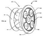
別の態様では、可変速度変速機が開示され、遊星歯車装置がさらに、縦軸と同軸で装着され、自身内に縦軸と同軸で分布して自身と係合する複数の遊星歯車に向かって半径方向内側に面する輪歯車とを備え、各遊星歯車は、自身が回転する中心となる個々の遊星軸を有し、遊星軸が縦軸から半径方向に離れて配置され、さらに各遊星歯車に1つずつ複数の遊星シャフトを備え、その周囲で遊星歯車が回転し、さらに縦軸と同軸で、複数の遊星歯車それぞれの半径方向内側で、それと係合して装着された太陽歯車と、縦軸と同軸で装着され、遊星シャフトを支持し、位置決めするような構成である遊星枠とを備える。 In another aspect, a variable speed transmission is disclosed, wherein the planetary gear set is further mounted coaxially with the longitudinal axis, toward the plurality of planetary gears coaxially distributed within the longitudinal axis and engaged therewith. With radially inwardly facing ring gears, each planet gear having its own planet shaft about which it rotates, the planet shafts being disposed radially away from the longitudinal axis, and in addition each planet gear A sun gear mounted with a plurality of planet shafts, one around each, around which the planet gears rotate and which are coaxially with the longitudinal axis and radially inward of each of the plurality of planet gears and engaged therewith; And a planet frame mounted coaxially with the longitudinal axis and configured to support and position the planet shaft.
これらの実施形態の幾つかはさらに、玉の傾斜可能な軸と位置合わせするような構成であり、玉の角度および半径方向位置を維持するような構成である保持器を備える。幾つかの実施形態では、入力トルクが遊星枠に供給され、遊星枠が入力ディスクに結合され、太陽歯車が保持器に結合し、輪歯車が固定されて、回転せず、出力トルクが出力ディスクによって変速機から供給される。 Some of these embodiments further include a retainer configured to align with the tiltable axis of the ball and configured to maintain the angular and radial position of the ball. In some embodiments, the input torque is supplied to the planetary frame, the planetary frame is coupled to the input disk, the sun gear is coupled to the cage, the ring gear is fixed and does not rotate, and the output torque is output disk Supplied by the transmission.
別の態様では、本明細書に記載された変速機の実施形態で使用するために、入力ディスクと玉とアイドラと出力ディスクの間の牽引力を増加する軸力を発生するような構成である軸力発生装置が開示される。幾つかの実施形態では、軸力発生装置が発生する軸力の量が、変速機の伝達比の関数である。他の実施形態では、入力ディスク、玉、出力ディスクおよびアイドラがそれぞれ、摩擦増大被覆材料で被覆された接触表面を有する。特定の実施形態の被覆材料はセラミックまたはサーメットである。さらに他の実施形態では、被覆は、窒化シリコン、シリコンカーバイド、無電解ニッケル、めっきニッケル、またはその組み合わせで構成されたグループから選択した材料である。 In another aspect, the shaft is configured to generate an axial force that increases the traction between the input disc, the ball, the idler, and the output disc for use in the transmission embodiments described herein. A force generator is disclosed. In some embodiments, the amount of axial force generated by the axial force generator is a function of the transmission ratio of the transmission. In another embodiment, the input disc, ball, output disc and idler each have a contact surface coated with a friction enhancing coating material. The coating material of certain embodiments is a ceramic or a cermet. In yet another embodiment, the coating is a material selected from the group consisting of silicon nitride, silicon carbide, electroless nickel, plated nickel, or a combination thereof.
さらに別の態様では、可変速度変速機が開示され、これは縦軸と、縦軸の周囲に放射状に分布する複数の玉を備え、各玉がその回転の中心となる傾斜可能な軸線を有し、さらに、玉に隣接して位置決めされ、各玉と接触する回転可能な入力ディスクと、入力ディスクの反対側で玉に隣接して位置決めされ、各玉と接触する固定された出力ディスクと、一定の外径を有し、各玉の半径方向内側に位置決めされて、それと接触する回転可能なアイドラと、玉の半径方向の位置および軸方向の位置合わせを維持するような構成であり、縦軸の周囲で回転可能である保持器と、アイドラに接続し、アイドラからトルク出力を受け取って、変速機からトルク出力を伝達するような構成であるアイドラシャフトとを備える。 In yet another aspect, a variable speed transmission is disclosed that includes a longitudinal axis and a plurality of balls distributed radially around the longitudinal axis, each ball having a tiltable axis about which it rotates A rotatable input disc positioned adjacent to and in contact with each ball, and a fixed output disc positioned adjacent to the ball on the opposite side of the input disc and in contact with each ball; A rotatable idler having a constant outer diameter, positioned radially inward of each ball, and configured to maintain radial position and axial alignment of the ball, longitudinal A retainer rotatable about an axis and an idler shaft connected to the idler, configured to receive torque output from the idler and to transmit torque output from the transmission.
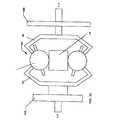
また別の態様では、可変速度変速機が記載され、これは縦軸の周囲に放射状に分布する複数の第1および第2玉と、回転可能な第1および第2入力ディスクと、縦軸と同軸であり、第1および第2入力ディスクと接続する入力シャフトと、複数の第1玉と第2玉との間に位置決めされ、複数の第1および第2玉それぞれと接触する回転可能な出力ディスクと、複数の第1玉それぞれの半径方向内側に位置決めされて、それと接触する概ね円筒形の第1アイドラと、複数の第2玉それぞれの半径方向内側に位置決めされて、それと接触する概ね円筒形の第2アイドラとを備える。 In yet another aspect, a variable speed transmission is described that includes a plurality of first and second balls radially distributed about a longitudinal axis, rotatable first and second input disks, and a longitudinal axis. A rotatable output coaxial with the input shaft connected to the first and second input disks, positioned between the plurality of first balls and the plurality of second balls and in contact with the plurality of first and second balls respectively A disc and a generally cylindrical first idler positioned radially inward of and contacting each of the plurality of first balls and a generally cylindrical positioned radially inward of and contacting each of the plurality of second balls And a second idler of a shape.
本明細書に記載された多くの実施形態で使用するために、軸力を加えて、入力ディスクと出力ディスクと複数の速度調節装置との間の接触力を増加させるような構成である軸力発生装置も開示され、軸力発生装置はさらに、縦軸と同軸で、その周囲で回転可能であり、外径および内径を有し、内径の中に形成されたねじ付きボアを有する軸受けディスクと、軸受けディスクの外径に近い方の第1側に取り付けられた複数の周囲傾斜路と、複数の軸受けディスク傾斜路と係合するような構成である複数の軸受けと、速度調節装置の反対側で入力ディスクに装着され、軸受けと係合するような構成である複数の入力ディスク周囲傾斜路と、縦軸と同軸で、その周囲で回転可能であり、外面に沿ってオスねじ山を有し、そのメスねじは軸受けディスクのねじ付きボアと係合するような構成である概ね円筒形のねじと、ねじに取り付けられた複数の中心ねじ傾斜路と、入力ディスクに固定され、複数の中心ねじ傾斜路と係合するような構成である複数の中心入力ディスク傾斜路とを備える。 An axial force that is configured to apply an axial force to increase the contact force between the input disc, the output disc, and the plurality of speed adjusters for use in the many embodiments described herein. A generating device is also disclosed, wherein the axial force generating device is further coaxial with the longitudinal axis, is rotatable around it, has an outer diameter and an inner diameter, and has a bearing disc with a threaded bore formed in the inner diameter. A plurality of circumferential ramps mounted on the first side closer to the outer diameter of the bearing disc, a plurality of bearings configured to engage with the plurality of bearing disc ramps, and the other side of the speed adjuster Mounted on the input disk and configured to engage with the bearings, with a plurality of input disk perimeter ramps, coaxial with the longitudinal axis, rotatable thereabout, with male threads along the outer surface , That female screw is a bearing A generally cylindrical screw configured to engage with the threaded bore of the screw, a plurality of central threaded ramps attached to the screw, fixed to the input disc and engaged with the plurality of central threaded ramps And a plurality of central input disc ramps of the type described.
別の態様では、回転牽引変速機内の複数の傾斜可能な速度調節玉を支持し、位置決めする支持保持器が開示され、これは複数の玉の各側で入力ディスクおよび出力ディスクを使用し、保持器は、それぞれが外縁から半径方向内側に延在する複数のスロットを有する概ね円形のシートである平坦な第1および第2支持ディスクと、前記第1支持ディスクと第2支持ディスクの間に延在する複数の平坦な支持スペーサとを備え、各スペーサは、それぞれ前側、後側、第1端および第2端を有し、第1および第2端がそれぞれ装着表面を有し、各装着表面が湾曲表面を有し、スペーサは、湾曲表面が溝の側部と位置合わせされるように、支持ディスクの周囲で支持ディスクの溝の間に角度を付けて位置決めされる。 In another aspect, a support cage is disclosed that supports and positions a plurality of tiltable speed adjustment balls in a rotary traction transmission, which uses and holds an input disc and an output disc on each side of the plurality of balls. The first support disc and the second support disc, the first support disc and the second support disc being flat circular first sheets each having a plurality of slots extending radially inward from the outer edge And a plurality of planar support spacers, each spacer having a front side, a rear side, a first end and a second end, each of the first and second ends having a mounting surface, each mounting surface Has a curved surface and the spacer is positioned at an angle between the grooves of the support disk around the support disk such that the curved surface is aligned with the sides of the groove.
さらに別の態様では、比率を決定する玉の回転軸を形成する軸を傾斜することによって回転牽引変速機の伝達比を変更する比率変更機構の支持脚が開示され、これは、細長い本体、軸接続端、軸接続端の反対側のカム端、玉に面する前側および玉に面していない後側、および軸接続端とカム端との間の中心支持部分を備え、凸状に湾曲するカム表面がカム端の前側に形成され、これはボアの位置合わせの制御を補助するような構成である。 In yet another aspect, a support leg of a ratio change mechanism is disclosed which changes the transmission ratio of a rotary traction transmission by tilting the axis forming the axis of rotation of the ball which determines the ratio, which comprises an elongated body, an axis Curved in a convex manner with a connection end, a cam end opposite the axial connection end, a front side facing the ball and a rear side not facing the ball, and a central support portion between the axial connection end and the cam end A cam surface is formed in front of the cam end, which is configured to assist in controlling the alignment of the bore.
可変速度回転牽引変速機に使用する流体給送玉の別の態様が開示され、これは個々の傾斜可能な軸線の周囲で回転可能である複数の玉、複数の玉それぞれの一方側にあって、それと接触する入力ディスク、および複数の玉それぞれの別の側にあって、それと接触する出力ディスクを使用し、流体給送玉は、自身の直径を通って形成され、自身を通る円筒形の内面を生成する球形の玉、および玉の内面に形成され、玉を通って延在する少なくとも1つの螺旋溝を備える。 Another aspect of a fluid feed ball for use in a variable speed rotary traction transmission is disclosed, which comprises a plurality of balls rotatable about individual tiltable axes, one side of each of the plurality of balls , Using an input disc in contact with it, and an output disc on another side of each of the plurality of balls, with which the fluid delivery ball is formed through its own diameter and is cylindrical A spherical ball producing an inner surface, and at least one spiral groove formed on the inner surface of the ball and extending through the ball.
また別の態様では、可変速度回転牽引変速機で使用する流体給送軸が開示され、これは自身を通って形成された直径方向のボアによって形成された個々の軸線を有する複数の玉、複数の玉それぞれの一方側にあって、それと接触する入力ディスク、複数の玉それぞれの別の側にあって、それと接触する出力ディスクを使用し、流体給送軸は、ボールを通るボアのそれより小さい直径で、第1および第2端および中央領域を有する概ね円筒形の軸を備え、軸を個々の玉のボア内に適切に位置決めすると、第1および第2端が玉の対向する側から外側に延在し、中央領域が玉の中にあり、さらに軸の外面に形成された少なくとも1つの螺旋溝を備え、螺旋溝は玉の外側の一点で開始して、中央領域の少なくとも一部の中へと延在する。 In yet another aspect, a fluid delivery shaft for use in a variable speed rotary traction transmission is disclosed, which has a plurality of balls, each having an individual axis formed by a diametrical bore formed therethrough. Using an input disc on one side of each of the balls and an output disc on the other side of each of the plurality of balls and in contact with it, the fluid delivery axis being from that of the bore through the ball A small diameter, generally cylindrical shaft having first and second ends and a central region, with the shaft properly positioned in the bore of the individual ball, the first and second ends from opposite sides of the ball Extending outwards, the central region being in the ball and further comprising at least one helical groove formed on the outer surface of the shaft, the helical groove starting at a point outside the ball, at least a portion of the central region Extend into the
別の実施形態では、縦軸を有する可変速度回転牽引変速機のシフト機構が開示され、これは平面に位置合わせされて、縦軸の周囲に分布する複数の傾斜玉を使用し、各玉は、変速機の伝達比を制御するために入力ディスクおよび出力ディスクによって対向する側に接触し、シフト機構は、縦軸に沿って延在する管状の伝達軸、それぞれが複数の玉のうち対応する玉を通って形成されたボアを通って延在し、玉が回転する中心となる対応の玉の傾斜可能な軸線を形成する複数の玉軸を備え、各玉軸は、それぞれが玉から外へと延在する2つの端を有し、さらに複数の脚部を備え、1つの脚部が玉軸の各端に接続され、脚部は、変換器軸に向かって半径方向内側へと延在し、さらに、変換器軸に同軸で位置合わせされ、各玉の半径方向内側にあって、それと接触するアイドラ、アイドラの各端に1つずつあり、それぞれがアイドラに面する平坦な側、およびアイドラに面していない凸状の湾曲した側を有する2つのディスク形シフトガイドを備え、シフトガイドが半径方向に延在して、玉の対応する側にある個々の脚部全部と接触し、さらに脚部ごとに1つある複数のローラプーリを備え、各ローラプーリが、玉に面していない個々の脚部の側部に取り付けられ、さらに、シフトガイドの少なくとも1つから軸方向に延在する概ね円筒形のプーリスタンド、各ローラプーリに1つあり、プーリスタンドの周囲に半径方向に分布して、それに取り付けられた複数の案内プーリ、および第1および第2端を有し、第1端が軸を通って延在し、プーリスタンドの近位側で軸に形成されたスロットから出る可撓性係留具を備え、係留具の第1端はさらに、各ローラプーリおよび各案内プーリに巻き付き、第2端は軸から出てシフタへと延在し、案内プーリはそれぞれ1つまたは複数の旋回継ぎ手に装着されて、各案内プーリとその個々のローラプーリとの位置合わせを維持し、係留具がシフタによって引っ張られると、第2端が各ローラプーリを引き込み、変速機をシフトさせる。 In another embodiment, a shift mechanism of a variable speed rotary traction transmission having a longitudinal axis is disclosed, which is aligned to a plane and uses a plurality of inclined balls distributed around the longitudinal axis, each ball The transmission mechanism is in contact with opposite sides by the input disc and the output disc to control the transmission ratio of the transmission, and the shift mechanism is a tubular transmission axis extending along the longitudinal axis, each corresponding to a plurality of balls A plurality of ball axes extending through bores formed through the balls and forming a tiltable axis of the corresponding ball about which the balls rotate are provided, each ball axis being outside the balls And two or more legs, one leg being connected to each end of the ball axis, the legs extending radially inward towards the transducer axis And also coaxially aligned with the transducer axis, and radially inward of each ball An idler in contact with it, two disc-shaped shift guides, one at each end of the idler, each with a flat side facing the idler and a convex curved side not facing the idler, A shift guide extends radially to contact all the individual legs on the corresponding side of the ball and further comprises a plurality of roller pulleys, one for each leg, each roller pulley facing the ball A generally cylindrical pulley stand attached to the side of each individual leg and not extending axially from at least one of the shift guides, one for each roller pulley, distributed radially around the pulley stand A slot having a plurality of guide pulleys attached thereto and first and second ends, the first end extending through the shaft and formed on the shaft proximally of the pulley stand The first end of the anchor further wraps around each roller pulley and each guide pulley, the second end extends out of the shaft and extends to the sifter, and the guide pulleys are each one or A plurality of pivot joints are mounted to maintain alignment of each guide pulley with its respective roller pulley, and when the tether is pulled by the sifter, the second end pulls in each roller pulley and shifts the transmission.
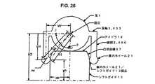
別の実施形態では、縦軸を有する可変速度変速機のシフト機構が開示され、これは変速機の伝達比を制御するために、それぞれが個々の玉の中心から玉の半径を有する複数の傾斜玉を使用し、それぞれが対応する玉を通って形成されたボアを通って延在し、対応する玉の傾斜可能な軸線を形成する複数の玉軸を備え、各玉軸は、それぞれが玉から延在する2つの端部を有し、さらに複数の脚部を備え、1つの脚部が玉軸の各端に接続され、脚部は、変速機軸に向かって半径方向内側に延在し、さらに、ほぼ一定の半径で、各玉と同軸で、その半径方向内側に位置決めされ、それと接触する概ね円筒形のアイドラ、アイドラの各端に1つずつあり、それぞれがアイドラに面する平坦な側、およびアイドラに面していない凸状の湾曲した側を有する第1および第2ディスク形シフトガイドを備え、シフトガイドは、半径方向に延在して、玉の対応する側にある個々の脚部全部と接触し、さらに、脚部ごとに1つずつあり、それぞれが案内ホィールの半径を有する複数の案内ホィールを備え、各案内ホィールが、個々の脚部の半径方向内側の端部に回転自在に装着され、案内ホィールは個々のシフトガイドの湾曲表面と接触し、凸状湾曲の形状が、1組の2次元座標によって決定され、その起点は縦軸と、直径方向に対向する任意の2つの玉の中心を通って引かれた線との交差点を中心とし、座標は、アイドラおよびシフトガイドの軸方向動作の関数として、案内ホィール表面とシフトガイド表面との間の接触点の位置を表し、凸状湾曲は、接触点において案内ホィールに対してほぼ接線であると仮定する。 In another embodiment, a shift mechanism of a variable speed transmission having a longitudinal axis is disclosed, which controls a plurality of tilts each having a ball radius from the center of an individual ball to control the transmission ratio of the transmission. A ball is used, comprising a plurality of ball axes, each extending through a bore formed through the corresponding ball, forming a tiltable axis of the corresponding ball, each ball axis being in each case a ball Having two ends extending therefrom and further comprising a plurality of legs, one leg being connected to each end of the ball axle, the legs extending radially inward towards the transmission axis In addition, there is a generally cylindrical idler, one at each end of the generally cylindrical idler, which is positioned radially inward and in contact with it, coaxially with each ball, with a substantially constant radius, each facing the idler Have a side and a convex curved side not facing the idler With first and second disc-shaped shift guides, the shift guides extend radially to contact all the individual legs on the corresponding side of the ball, one for each leg A plurality of guide wheels each having a radius of a guide wheel, each guide wheel being rotatably mounted on the radially inner end of an individual leg, the guide wheel being associated with a curved surface of an individual shift guide Contact and the shape of the convex curve is determined by a set of two-dimensional coordinates, the origin of which is the intersection point of the longitudinal axis and the line drawn through the centers of any two diametrically opposed balls Centered, the coordinates represent the position of the point of contact between the guiding wheel surface and the shifting guide surface as a function of the axial movement of the idler and the shifting guide, the convex curvature being approximately at the contact point relative to the guiding wheel Tangent Suppose there.
また別の実施形態では自動車が開示され、これはエンジン、動力伝達経路、ならびに可変速度変速機を備え、これは縦軸、縦軸の周囲で半径方向に分散した複数の玉を備え、各玉は、自身の回転中心である傾斜可能な軸線を有し、さらに、玉に隣接して位置決めされ、各玉と接触する回転可能な入力ディスク、入力ディスクの反対側で玉に隣接して位置決めされ、各玉と接触する回転可能な出力ディスク、縦軸と同軸でほぼ一定の外径を有し、各玉の半径方向内側に位置決めされて、それと接触する回転可能なアイドラ、および変速機の縦軸と同軸で装着された遊星歯車装置を備える。 In yet another embodiment, a motor vehicle is disclosed, which includes an engine, a power transmission path, and a variable speed transmission, which includes a plurality of radially distributed balls about the longitudinal axis, each ball Has its tiltable axis, which is its own center of rotation, and is positioned adjacent to the balls and is positioned adjacent to the balls on the opposite side of the input disc, the rotatable input disc in contact with each ball A rotatable output disk in contact with each ball, a rotatable idler coaxial with the longitudinal axis, having a substantially constant outer diameter, positioned radially inward of each ball and in contact therewith, and the longitudinal axis of the transmission A planetary gear set mounted coaxially with the shaft.
以上および他の改良点は、以下の詳細な説明を読み、添付の図面を見ると、当業者には明白になる。 These and other improvements will be apparent to those of ordinary skill in the art upon reading the following detailed description and viewing the accompanying drawings.
本発明の好ましい実施形態について以下に図面を参照して説明する。ここで、同様の数字は全体を通して同様の要素を指す。本明細書で提示された記述で使用する用語は、限定的には解釈されないものとする。これは単に、本発明の特定の実施形態に関する詳細な記述との組み合わせで使用されるからである。さらに、本発明の実施形態は、幾つかの新規の形態を含むことがあり、そのいずれも単独では所望の属性に寄与しないか、本明細書に記載された本発明の実践に必要不可欠ではない。 The preferred embodiments of the present invention will be described below with reference to the drawings. Here, similar numbers refer to similar elements throughout. The terms used in the description presented herein are not to be construed as limiting. This is merely to be used in combination with the detailed description of a specific embodiment of the present invention. Furthermore, embodiments of the present invention may include several novel forms, none of which alone contributes to the desired attributes or is not essential to the practice of the invention described herein. .
本明細書に記載された変速機は、米国特許第6,241,636号、米国特許第6,322,475号および米国特許第6,419,608号に記載されたような傾斜する軸を伴う速度調節装置の玉を使用するタイプである。本特許に記載され、本明細書に記載された実施形態は通常、下記のように変動装置の部分によって概ね分離された2つの側、つまり入力側および出力側を有する。変速機の駆動側、つまり変速機へのトルクまたは回転力を受ける側を入力側と予備、変速機の被動側または変速機からのトルクを変速機の外へと伝達する側を出力側と呼ぶ。入力ディスクおよび出力ディスクが速度調節装置の玉と接触する。玉がその軸上で傾斜するにつれ、一方のディスクと回転接触する点が玉の極または軸線に向かって移動し、したがって直径が増加する円でディスクに接触する。玉の軸が反対方向に傾斜すると、入力および出力ディスクがそれぞれ逆の関係を経験する。この方法で、入力ディスクの回転速度の出力ディスクのそれに対する比率、つまり伝達比は、速度調節装置の玉の軸を単に傾斜することによって、広範囲にわたって変更することができる。玉の中心が、変速機の入力側と出力側の間の境界を画定し、玉の入力側および玉の出力側の両方に位置する同様の構成要素を、本明細書では全体的に同じ参照番号で記述する。変速機の入出力側の両方に位置する同様の構成要素は、全体的に入力側に位置する場合は参照番号の末尾に添え字の「a」が付けられ、変速機の出力側に位置する構成要素は、個々の参照番号の末尾に添え字の「b」が付けられる。 The transmissions described herein have inclined shafts as described in U.S. Patent Nos. 6,241,636, 6,322,475 and 6,419,608. It is the type that uses the ball of the accompanying speed regulator. The embodiments described in this patent and described herein generally have two sides, an input side and an output side, generally separated by parts of the variable device as described below. The drive side of the transmission, that is, the side that receives torque or rotational force to the transmission is called the input side, and the side that transmits the torque from the transmission or the driven side of the transmission to the outside of the transmission is called the output side. . The input and output disks make contact with the ball of the speed regulator. As the ball tilts on its axis, the point of rolling contact with one of the discs moves towards the pole or axis of the ball and thus contacts the disc in a circle of increasing diameter. When the ball axis tilts in the opposite direction, the input and output disks experience opposite relationships, respectively. In this way, the ratio of the rotational speed of the input disc to that of the output disc, ie the transmission ratio, can be varied over a wide range simply by tilting the ball axis of the speed regulator. The center of the ball defines the boundary between the input and the output of the transmission, the same reference being made throughout the present specification to similar components located on both the input and output of the ball. Describe by number. Similar components located on both the input and output sides of the transmission are located on the output side of the transmission with the suffix "a" appended to the end of the reference number if located generally on the input side Components are suffixed with "b" at the end of each reference number.
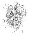
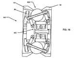
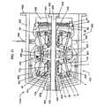
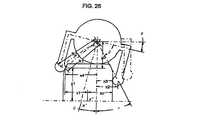
図1を参照すると、周囲に複数の速度調節玉1が半径方向に分布した縦軸11を有する変速機100の実施形態が図示されている。幾つかの実施形態の速度調節玉1は、縦軸11の周囲でその角度位置に留まり、他の実施形態では、玉1は縦軸11の周囲で自由に軌道を描く。玉11はその入力側が入力ディスク34と、出力側が出力ディスク101と接触する。入力および出力ディスク34、101は、玉1の個々の入力および出力側にある縦軸付近の内部ボアから、それぞれが玉1と接触する半径方向の点まで延在する環状ディスクである。入力および出力ディスク34、101はそれぞれ、各ディスク34および101と玉1との間に接触区域を形成する接触表面を有する。概して、入力ディスク34が縦軸11の周囲で回転するにつれ、入力ディスク34の接触区域の各部分が回転し、各回転中に玉1のそれぞれと順次接触する。これは、出力ディスク101でも同様である。入力ディスク34および出力ディスク101は、単純なディスクとして形成するか、所望の入力および出力の構成に応じて、凹状、凸状、円筒形、または他の任意の形状でよい。1つの実施形態では、入力および出力ディスクにスポークを付けて、重力に影響されやすい用途のために軽量化する。速度調節玉と係合するディスクの回転接触表面は、用途のトルクおよび効率の要件に応じて、平坦、凹状、凸状、または他の形状の輪郭を有してよい。ディスクが玉に接触する凹状の輪郭は、滑動を防止するために必要な軸力の量が減少し、凸状の輪郭は効率を向上させる。また、玉1は全て、個々の半径方向最内点でアイドラ18に接触する。アイドラ18は概ね円筒形の構成要素で、縦軸11と同軸であり、玉1の半径方向の位置の維持を補助する。変速機の多くの実施形態の縦軸11を参照すると、入力ディスク34と出力ディスク101の接触表面を、玉1の中心から概ね半径方向外側に配置することができ、アイドラ18は、玉1の半径方向内側に配置し、したがって各玉1はアイドラ18、入力ディスク34および出力ディスク101と3点接触する。入力ディスク34、出力ディスク101およびアイドラ18は全て、多くの実施形態で同じ縦軸11を中心に回転することができ、それについて以下でさらに詳細に説明する。 Referring to FIG. 1, an embodiment of a
本明細書に記載された変速機100の実施形態は回転牽引変速機であることから、幾つかの実施形態では、入力ディスク34および出力ディスク101が玉1との接点で滑るのを防止するために、高い軸力が必要である。高いトルク伝達の期間中に軸力が増加するにつれ、入力ディスク34、出力ディスク101およびアイドラ18が玉1と接触する接触パッチの改造が重大な問題となり、これらの構成要素の効率および寿命を低下させる。これらの接触パッチを通して伝達できるトルクの量は有限であり、玉1、入力ディスク34、出力ディスク101およびアイドラ18を作成する材料の降伏強さの関数である。玉1、入力ディスク34、出力ディスク101およびアイドラ18の摩擦係数は、所与の量のトルクを伝達するために必要な軸力の量に多大な影響を及ぼし、したがって変速機の効率および寿命に多大な影響を及ぼす。牽引変速機の回転要素の摩擦係数は、性能に栄養する非常に重要な変数である。 Because the embodiments of the
特定のコーティングを玉1、入力ディスク34、出力ディスク101およびアイドラ18に適用して、その性能を改良することができる。実際、このようなコーティングを任意の回転牽引変速機の回転接触要素に都合よく使用して、本明細書で開示する変速機の実施形態で達成したのと同じ追加の利点を達成することができる。これらの回転要素の表面の摩擦係数を上げるという有益な効果を有するコーティングもある。高い摩擦係数を有し、軸力が増加するにつれて増加する変動性の摩擦係数も呈するコーティングもある。摩擦係数が大きいと、任意のトルクに必要な軸力を小さくすることができ、それによって変速機の効率および寿命が向上する。可変の摩擦係数は、最大トルクを伝達するために必要な軸力の量を減少させることによって、変速機のこの最大トルク底角を増加させる。 Specific coatings can be applied to
セラミックおよびサーメットのように、非常に優れた硬度および摩耗特性を有し、回転牽引変速機の高負荷回転要素の寿命を大幅に延長することができるコーティングもある。窒化シリコンのようなセラミックコーティングは高い摩擦係数、磁区力の増加とともに増加する可変摩擦係数も有することができ、玉1、入力ディスク34、出力ディスク101おおよびアイドラ18の表面に非常に薄い層で適用すると、これらの構成要素の寿命を延長することもできる。コーティングの厚さは、コーティングに使用する材料によって決定され、用途に応じて変化してよいが、通常はセラミックの場合は0.5ミクロンから2ミクロンで、サーマットの場合は0.75ミクロンから4ミクロンの範囲である。 Some coatings, such as ceramics and cermets, have very good hardness and wear properties and can significantly extend the life of the high load rotating elements of a rotary traction transmission. Ceramic coatings such as silicon nitride can also have a high coefficient of friction, a variable coefficient of friction that increases with increasing magnetic domain forces, with very thin layers on the surface of
玉1、入力ディスク34、出力ディスク101およびアイドラ18を、本明細書に記載された変速機の多くの実施形態で使用する材料である焼き入れ鋼から作成した場合は、コーティングの適用に用いるプロセスを考慮することが重要である。セラミックおよびサーマットの適用に用いるプロセスには、高い温度を必要とし、玉1、入力ディスク34、出力ディスク101およびアイドラ18の硬度を低下させて、性能を損ない、時期尚早の不具合に寄与するものもある。低温で適用するプロセスが望ましく、低温真空プラズマ、DCパルス型反応マグネトロンスパッタリング、プラズマ促進化学蒸着(PE−CVD)、不平衡マグネトロン物理蒸着、およびめっきなど、幾つかのプロセスが使用可能である。めっきプロセスは、低コストであり、所望のコーティング特性を達成するために特注の槽を作成できるので魅力的である。シリコンカーバイドまたは窒化シリコンと共析出した無電解ニッケルまたはめっきニッケルを含むシリコンカーバイドまたは窒化シリコンの槽に回転要素を浸漬することは、大量生産に非常に適した低温の解決法である。記載された材料に加えて、他の材料を使用できることに留意されたい。この適用プロセスでは、部品を保持器に含め、槽に浸漬して、溶液が全表面と接触するように振る。コーティングの厚さは、構成要素が槽内に浸漬される時間の長さによって制御する。例えば、共析出した無電解ニッケルとともに窒化シリコンを使用して、構成要素を4時間浸漬し、適切なコーティングを達成する実施形態もあるが、これは、一例にすぎず、コーティングを形成して、その厚さを制御する多くの方法が知られ、所望の特性、所望の厚さ、および構成要素を作成する基質または母材を考慮して、これを使用することができる。 The process used to apply the coating when
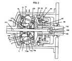
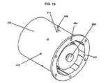
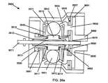
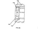
図1、図2および図3は、ケース40に覆われた連続可変変速機100の実施形態を示し、ケースは変速機100を保護し、潤滑剤を含み、変速機100の構成要素を位置合わせし、変速機100の力を吸収する。ケースのキャップ67は、特定の実施形態ではケース40を覆うことができる。ケースキャップ67は、概ねボアのあるディスクとして形成され、ボアの中心を入力シャフトが通り、ケース40の内径にあって対応するねじ山の組にねじ込まれるねじ山の組が外径にある。しかし、他の実施形態では、ケースキャップ67はケース40に締結するか、ばねリングおよびケース40の対応する溝によって所定の位置に保持することができ、したがって外径にねじを切る必要がない。ケースキャップ67を取り付けるために締結具を使用する実施形態では、ケースキャップ67がケース40の内径へと延在し、したがって、変速機100を取り付ける先の機械にケース40をボルト締めするために使用するケース締結具(図示せず)は、ケースキャップ67の対応する穴を通ることができる。図示の実施形態のケースキャップ67は、変速機100の他の構成要素を追加的に支持するために、外径付近の区域から変速機100の出力側に向かって延在する円筒形部分を有する。図示の変速機100の実施形態の心臓部には複数の玉1があり、これは通常は球形であり、変速機100の中心線、つまり回転の縦軸11の周囲でほぼ均一または対称にて半径方向に分布する。図示の実施形態では、8つの玉1を使用する。しかし、変速機100の使用法に応じて異なる数の玉1を使用できることに留意されたい。例えば、変速機は3、4、5、6、7、8、9、10、11、12、13、14、15またはそれ以上の玉を含んでよい。3、4または5個以上の玉を設けると、個々の玉1に加えられる力、および変速機100の他の構成要素との接触点をさらに広く分配することができ、変速機100が玉100の接触パッチで滑るのを防止するために必要な力も削減することができる。低トルクを適用するが伝達比が高い特定の実施形態は、比較的大きい直径の玉1を少なめに使用するが、大きいトルクおよび高い伝達比を適用する特定の実施形態は、比較的大きい直径の玉1を多めに使用することができる。大きいトルクおよび低い伝達比を適用し、高い効率が重要ではない他の実施形態は、比較的小さい直径の玉1を多めに使用する。最後に、小さいトルクを適用し、高い効率が重要ではない特定の実施形態は、比較的小さい直径の玉1を少なめに使用する。 1, 2 and 3 show an embodiment of a continuously
玉1それぞれの中心を通って各玉1の回転軸を画定する穴に、玉の軸3を挿入する。玉軸3は、その上で玉1が回転する概ね細長いシャフトであり、穴の各側から延在して玉1を通る2つの端部を有する。特定の実施形態は円筒形の玉軸3を有するが、任意の形状を使用することができる。玉1は、玉軸3の周囲で自由に回転するように装着する。 The
特定の実施形態では、軸受け(別個に図示せず)を使用して、玉軸3の外面と対応する玉1を通るボアの表面との間の摩擦を軽減する。これらの軸受けは、玉1とそれに対応する玉軸3との接触表面に沿った任意の場所に位置する任意のタイプの軸受けでよく、多くの実施形態は、動的機械システムの設計に共通する標準的な機械的減速により、このような軸受けの寿命および有用性を最大にする。これらの実施形態の一部では、玉1を通るボアの各端にラジアル軸受けを配置する。これらの軸受けは、ボアの内面および玉軸3の外面を軌道輪として組み込むか、軸受けは、各玉1のボア内および各玉軸3上に形成された適切な空隙に填る別個の軌道輪を含むことができる。1つの実施形態では、ラジアル軸受け、ころ、玉または他のタイプをこのように形成した空隙内に填め、保持できるように、各玉を通るボアを少なくともその両端で適切な直径に拡張することによって、軸受けの空隙(図示せず)を形成する。別の実施形態では、バビット、テフロン(登録商標)または他のこのような材料など、摩擦を軽減する材料で玉軸3を被覆する。 In a particular embodiment, bearings (not separately shown) are used to reduce friction between the outer surface of the
多くの実施形態は、玉軸3のボアに潤滑剤を導入して、玉軸3と玉1との間の摩擦も最小限に抑える。潤滑剤は、圧力源によって玉軸3の周囲でボアに注入するか、玉軸3自体に形成した施条または螺旋溝によってボアに引き込むことができる。玉軸3の潤滑については、以下でさらに検討する。 Many embodiments introduce a lubricant into the bore of the
図1では、玉1の回転軸が変速機を出力速度が入力速度より大きい高い比率にする方向に傾斜した状態で図示される。玉軸3が水平である、つまり変速機100の主軸に平衡である場合、変速機100は入力回転速度と出力回転速度との比率が1:1であり、入力と出力の回転速度が等しい。図2では、玉1の回転軸が、変速機100を低い比率にする方向に傾斜した状態で図示されている。つまり、出力回転速度が入力回転速度より遅い。単純にするために、変速機100をシフトした場合に位置または方向が変化する部品のみに、図2では番号を付けている。 In FIG. 1, the axis of rotation of the
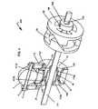
図1、図2、図4および図5は、作動時に変速機100をシフトするために、玉1の軸線を傾斜できる方法を示す。図5を参照すると、大部分の実施形態では支柱である複数の脚部2が、玉1を通してあけた穴の端部を越えて延在する玉軸3の各端部付近で、玉軸3に取り付けられる。各脚部2は、個々の玉軸3への取り付け点から半径方向内側に変速機100の軸線に向かって延在する。1つの実施形態では、各脚部2は玉軸3の一方の個々の端部を受け取る貫通ボアを有する。玉軸3は、各脚部2を越えて露出した端部を有するように、脚部2を通って延在することが好ましい。図示の実施形態では、玉軸3は、玉軸3の露出した端部と同軸で、その上に滑動自在に位置決めされたローラ4を有すると有利である。ローラ4は、脚部2の外側で、それを越えて玉軸3上に取り付けた概ね円筒形のホィールであり、玉軸3の周囲で自由に回転する。ローラ4は、ばねクリップまたは他のこのような機構を介して玉軸3に取り付けるか、玉軸3上に自由に載ることができる。ローラ4は、例えばラジアル軸受けにすることができ、軸受けの外輪がホィールまたは回転表面を形成する。図1および図7で示すように、ローラ4および玉軸3の端部は、1対の固定子80a、80bによって、またはその中に形成された溝86の内側に填る。 Figures 1, 2, 4 and 5 show how the axis of the
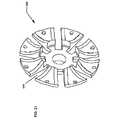
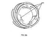
1つの実施形態の固定子80a、80bを図5および図7に示す。図示の入力固定子80aおよび出力固定子80bは概ね平行のディスクの形態であり、変速機の縦軸11の周囲で玉1の各側に環状に配置される。多くの実施形態の固定子80a、80bは、それぞれ入力固定子ディスク81aおよび出力固定子ディスク81bで構成され、これはほぼ均一な厚さで、以下でさらに検討する複数の開口がある概ね環状のディスクである。各入力および出力固定子ディスク81a、81bは、玉1に面する第1側、および玉1に面していない第2側を有する。複数の固定子曲線81が固定子ディスク81a、81bの第1側に取り付けられる。固定子曲線82は、固定子ディスク81a、81bに取り付けるか固定した曲線表面であり、それぞれが玉1に面する凹状面90、おおよび玉1に面していない凸状面91を有し、個々の固定子ディスク81と接触する。幾つかの実施形態では、固定子曲線82が固定子ディスク81a、81bと一体である。多くの実施形態の固定子曲線82は、ほぼ均一の厚さを有し、固定子曲線82を相互に、および固定子ディスク81に位置合わせして、取り付けるために使用する少なくとも1つの開口(別個に図示せず)を有する。多くの実施形態の固定子曲線82、または一体部品を使用する場合は固定子ディスク81a、81bは、平坦なスペーサ83を受け入れるスロット710を含み、これによって固定子曲線82および固定子ディスク81a、81bをさらに位置決めし、位置合わせすることができる。平坦なスペーサ83は概ね平坦であり、概ね長方形の剛性材料の部片であって、入力固定子80aと出力固定子80bの間に延在して、それを相互接続する。平坦なスペーサ83は、固定子曲線82内に形成されたスロット710内に填る。図示の実施形態では、平坦なスペーサ83が固定子曲線82に締結または他の方法で接続されないが、幾つかの実施形態では、平坦なスペーサ83は溶接、接着または締結によって固定子曲線82に取り付けられる。 One embodiment of a
図7でも示すように、少なくとも各端部にボアがあって概ね円筒形の複数の円筒形スペーサ84が、平坦なスペーサ83の内側に半径方向に位置決めされ、固定子ディスク81および固定子曲線82にも接続される。円筒形スペーサ84のボアは、各端で1つのスペーサ締結具85を受け入れる。スペーサ締結具85は、集合的に保持器89を形成する固定子ディスク81a、81b、固定子曲線82、平坦なスペーサ83および円筒形スペーサ84をまとめて締め付けて、保持するように設計される。保持器89は、玉1の半径方向および角度位置を維持し、玉1を相互に対して位置合わせする。 As also shown in FIG. 7, a plurality of generally cylindrical
玉1の回転軸は、入力側または出力側の脚部2を変速機100の軸線から半径方向外側に移動させることによって変化し、これは玉軸3を傾斜させる。こうなるにつれ、各ローラ4が溝86に填って、これに従い、これはローラ4の直径よりわずかに大きく、隣接する固定子曲線82の各対の間のスペースによって形成される。したがって、ローラ4は、玉軸3の運動面を変速機100の縦軸11と一直線上に維持するために、固定子曲線82の側部92、93、各固定子曲線82の第1側92および第2側に沿って回転する。多くの実施形態では、各ローラ4は、変速機100の入力側では固定子曲線82の第1側92で、および対応する出力固定子曲線82の対応する第1側92で回転する。通常、このような実施形態では変速機100の力が通常の動作ではローラ4が固定子曲線82の第2側93に接触するのを防止する。ローラ4は、固定子曲線82間に形成される溝86の幅より直径がわずかに小さく、溝86の縁部と対応する各ローラの周囲との間に小さいギャップを形成する。入力固定子80aおよび出力固定子80b上の対向する固定子曲線82の組が完全に位置合わせされている場合は、ローラ4の周囲と溝86との間の小さいギャップによって、玉軸がわずかに傾斜することができ、変速機100の縦軸11に対して位置不良になることがある。この状態は横滑りを生じる。これは玉軸3が横方向にわずかに移動できる状況で、変速機の全体的な効率を低下させる。幾つかの実施形態では、変速機100の入力および出力側にある固定子曲線82は、相互からわずかにオフセットし、したがって玉軸3が変速機100の軸線と平行なままである。玉1が玉軸3に加える任意の接線力、主に横断力は、玉軸3、ローラ4、および固定子曲線82の第1側92、93によって吸収される。玉1の回転軸を変化させて、変速機100を異なる伝達比へとシフトするにつれ、1つの棚軸3の対向する端部に位置するローラ4の各対が、溝86の個々の側を上下に回転することによって、個々の対応する溝86に沿って反対方向に移動する。 The axis of rotation of the
図1および図7を参照すると、保持器89は1つまたは複数のケースコネクタ160でケース40にしっかり取り付けることができる。ケースコネクタ160は、平坦なスペーサ83の半径方向で最も外側の部品からほぼ直角に延在する。ケースコネクタ160は、平坦なスペーサ83に締結するか、平坦なスペーサ83と一体形成することができる。ケースコネクタ160の外側によってほぼ形成された外径は、ケース40の内径とほぼ同じ直径であり、ケース40およびケースコネクタ160の穴によって、標準的または特殊な締結具を使用することができ、これはケースコネクタ160をケース40にしっかり取り付け、したがってケース40を補強して、その動作を防止する。ケース40は、ケース40を枠または他の構造的本体に取り付けることができる装着穴を有する。他の実施形態では、ケースコネクタ160は、ケース40の部品として形成することができ、保持器89を可動化するために平坦なスペーサ83または他の保持器89構成要素の取り付け位置を提供する。 With reference to FIGS. 1 and 7, the
図1、図5および図7は、各脚部2に取り付けられ、側部92、93それぞれに近い路に沿って湾曲した表面82の凹面90上で回転する1対の固定子ホィール30を含む実施形態を示す。固定子ホィール30は、概ね玉軸3が脚部2を通る区域で脚部2に取り付けられる。固定子ホィール30は、脚部2を通るボアを通って玉軸3に対して概ね直角である固定子ホィールピン31で、または他の任意の取り付け方法で脚部2に取り付けることができる。固定子ホィール30は、固定子ホィールピン31と同軸で、これに滑動自在に装着され、例えばスナップリングなどの標準的な締結具で固定される。幾つかの実施形態では、固定子ホィール30は、名輪が固定子ホィールピン31に装着され、外輪が回転表面を形成するラジアル軸受けである。特定の実施形態では、脚部2の各側に1つの固定子ホィール30を位置決めし、脚部2からのクリアランスは十分にあって、それにより固定子ホィール30は、変速機100をシフトすると変速機100の縦軸11に対して凹面90に沿って半径方向に回転することができる。特定の実施形態では、凹面90は、玉1の中心によって形成された変速機100の縦軸11からの半径の周囲で同心であるように成形される。 Figures 1, 5 and 7 include a pair of
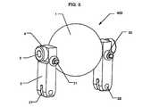
さらに図1、図5および図7を参照すると、変速機100の縦軸11に近い方の脚部2の端部に取り付けることができる案内ホィール21が図示されている。図示の実施形態では、案内ホィール21は、脚部2の端部内のスロットに挿入する。案内ホィール21は、案内ホィールピン22で、または任意の他の取り付け方法によって脚部21のスロット内にある所定の位置に保持される。案内ホィール21は案内ホィールピン22と同軸で、それに滑動自在に装着され、これは案内ホィールの各側で脚部2内に形成され、スロットの面に対して直角であるボアに挿入される。幾つかの実施形態では、脚部2は、変速機100の部品の製造公差を斟酌するために、比較的わずかに弾性屈曲するように設計される。玉1、脚部2、玉軸3、ローラ4、固定子ホィール30、固定子ホィールピン31、案内ホィール21、および案内ホィールピン22はまとめて、図5に見られる玉/脚部アセンブリ403を形成する。 With further reference to FIGS. 1, 5 and 7, a
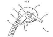
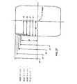
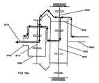
図4、図6および図7で示す実施形態を参照すると、ケース40の外側に位置決めされた棒10を回転することによって、シフトを実行する。棒10を使用して、可撓性入力ケーブル155aおよびそれに取り付けた可撓性出力ケーブル155bに、その個々の第1端部で巻き付け、ほどき、個々の反対方向で棒10に巻き付ける。幾つかの実施形態では、棒10を図6で示した状態で右から左を見て、入力ケーブル155aを反時計回り方向で棒10に巻き付け、出力ケーブル155bを時計回り方向で棒10に巻き付ける。入力ケーブル155aおよび出力ケーブル155bは両方とも、ケース40の穴を通って延在し、次に可撓性入力ケーブルハウジング151aの第1端および可撓性出力ケーブルハウジング151bを通る。図示の実施形態の可撓性入力ケーブルハウジング151aおよび可撓性出力ケーブルハウジング151bは、可撓性の細長い管であり、入力ケーブル155aおよび出力ケーブル155bを半径方向内側に縦軸11に向かって案内し、次に固定子ディスク81a、81bを通って長手方向に出て、再び半径方向内側に案内し、ここで可撓性入力および出力ケーブルハウジング151a、151bの第2端が、それぞれ剛性入力および出力ケーブルハウジング153a、153bの第1端に挿入され、取り付けられる。剛性入力および出力ケーブルハウジング153a、153bは不撓性の管であり、これをケーブル155a、155bが通り、可撓性ケーブルハウジング151a、151bの第2端から半径方向内側に案内され、次にケーブル155a、155bを長手方向に配向して、固定子ディスク81a、81bの穴に通して、アイドラ18付近の剛性ケーブルハウジング153a、153bの第2端に向ける。多くの実施形態では、ケーブル155a、155bは、その第2端が入力シフトガイド13aおよび出力シフトガイド13b(以下でさらに説明)に従来のケーブル締結具または他の適切な取り付け手段で取り付けられる。以下でさらに検討するように、シフトガイド13a、13bは、縦軸11に沿って軸方向にアイドラ18を位置決めして、半径方向に脚部3を位置決めし、それによって玉1の軸線および変速機100の比率を変化させる。 Referring to the embodiments shown in FIGS. 4, 6 and 7, the shift is performed by rotating the
使用者が手動で、または動力源の補助で棒10を棒10の軸線に対して図6で示すように右側から左側へと反時計回り方向に回転すると、入力ケーブル155aが棒10からほどけて、出力ケーブル155bが棒10に巻き付く。したがって、出力ケーブル155bの第2端が張力を出力シフトガイド13bに加え、入力ケーブル155aが釣り合った量だけ棒10からほどける。これは、アイドラ18を変速機100の出力側に向かって軸方向に動作させ、変速機100をローにシフトする。 When the user rotates
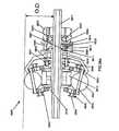
さらに図4、図5および図7を参照すると、図示されたシフトガイド13a、13bはそれぞれ、内径および外径がある概ね環状リングの形態であり、2つの側を有するように成型される。第1側は、個々のシフトガイド13a、13bにそれぞれ関連する2組のアイドラ軸受け17a、17bを介してアイドラに動的に接触して、軸方向に支持する概ね直線の表面である。各シフトガイド13a、13bの第2側、つまりアイドラ18に面していない側は、シフトガイド13a、13bの内側の7Xe erに向かう直線または平
坦な半径方向の表面14から、シフトガイド13a、13bの外径へと向かう凸状曲線97へと遷移するカム側である。シフトガイド13a、13bの内径にて、長手方向の管状スリーブ417a、417bが、対向するシフトガイド13a、13bからの管状スリーブ417a、417bと対合するために、そのシフトガイド13a、13bに向かって軸方向に延在する。幾つかの実施形態では、図4で示すように、入力側シフトガイド13aの管状スリーブが、出力シフトガイド13bの管状スリーブを受け取るために、ボアを形成したその内径の部分を有する。相応して、出力シフトガイド13bの管状スリーブの外径の一部が除去されて、その管状スリーブ417a、417bの部分を入力シフトガイド13aの管状スリーブ417a、417bに挿入することができる。これは、このような実施形態のシフトガイド13a、13bに追加の安定性を提供する。With further reference to FIGS. 4, 5 and 7, the illustrated shift guides 13a, 13b are each in the form of a generally annular ring having an inner diameter and an outer diameter and are molded to have two sides. The first side is a generally straight surface which supports axially in dynamic contact with the idler via two sets of
図4で示すシフトガイド13a、13bの側断面図は、この実施形態で、玉軸3が変速機100の縦軸11と平行である場合、面していない側部の平坦な表面14の輪郭は、案内ホィール21がシフトガイド13a、13bと接触する半径方向の点まで直角であることを示す。この点からシフトガイド13a、13bの周囲に向かうと、シフトガイド13a、13bの輪郭が凹形に湾曲する。幾つかの実施形態では、シフトガイド13a、13bの凸状曲線97は1つの半径ではなく、複数の半径で構成されるか、双曲線で、漸近的に、または他の方法で成形する。変速機100をローに向かってシフトするにつれ、入力案内ホィール21aがシフトガイド13aの平坦14部分の縦軸11に向かって回転し、出力案内ホィール21bが、シフトガイド13bの凸状湾曲97部分で縦軸11から離れる方向に回転する。シフトガイド13a、13bは、オスねじを有する入力シフトガイド13aの管状スリーブと、メスねじを有する出力スリーブ13bの管状スリーブとを、またはその逆をねじ込むことによって相互に取り付けて、シフトガイド13a、13bを相互にねじ込むことができる。入力または出力の一方のシフトガイド13a、13bも、他方のシフトガイド13a、13bに押し込むことができる。シフトガイド13a、13bは、接着剤、金属接着剤、溶接または他の任意の手段など、他の方法で取り付けることもできる。 The side sectional view of the shift guides 13a, 13b shown in FIG. 4 is, in this embodiment, the contour of the non-facing side
2つのシフトガイド13a、13bの凸状曲線97はカム表面として作用し、それぞれが複数の案内ホィール21と接触して、これを押す。各シフトガイド13a、13bの平坦表面14および凸状曲線97は案内ホィール21と接触し、したがってシフトガイド13a、13bが縦軸11に沿って軸方向に移動するにつれ、案内ホィール21がシフトガイド13a、13bに沿って表面14、97に概ね半径方向に乗り上げ、脚部2を縦軸11から外側へ、またはそれに向かって内側へと半径方向に移動させ、それによって玉軸3と関連する玉1の回転軸との角度を変化させる。 The
図4および図7を参照すると、幾つかの実施形態のアイドラ18は、第1側とシフトガイド13a、13bのスリーブ部分の間に形成されたトラフに配置され、したがってシフトガイド13a、13bと一体で動作する。特定の実施形態では、アイドラ18は概ね管状で、外側のダイアメットが1つであり、内径の中心部分に沿ってほぼ円筒形であり、内径の各端に入力および出力アイドラ軸受け17a、17bがある。他の実施形態では、アイドラ18の外径および内径は不均一でよく、変動するか、傾斜または曲線などの任意の形状でよい。アイドラ18は2つの側を有し、一方は入力固定子80aに近く、一方は出力固定子80bに近い。アイドラ軸受け17a、17bは、アイドラ18とシフトガイド13a、13bの間に回転接触を提供する。アイドラ軸受け17a、17bは、シフトガイド13a、13bのスリーブ部分の周囲に同軸で配置され、これによってアイドラ18は変速機100の軸線の周囲で自由に回転することができる。スリーブ19は変速機100の縦軸11の周囲に、およびシフトガイド13a、13bの内径の内側に填る。スリーブ19は、入力スリーブ軸受け172aおよび出力スリーブ軸受け172bによって各シフトガイド13a、13bの軸受け軌道輪の内面と動作自在に接触する状態で保持される概ね管状の構成要素である。スリーブ軸受け172a、172bは、シフトガイド13a、13bの軌道輪に対して相補的に軸受けの外輪に沿って回転することによって、スリーブ19の回転を提供する。アイドラ18、アイドラ軸受け17a、17b、スリーブ19、スリーブガイド13a、13b、およびスリーブ軸受け172a、172bは集合的に図4で見られるアイドラアセンブリ402を形成する。 With reference to FIGS. 4 and 7, the idler 18 of some embodiments is disposed in a trough formed between the first side and the sleeve portion of the shift guides 13a, 13b and thus integral with the shift guides 13a, 13b. Works with In a particular embodiment, the idler 18 is generally tubular, with one outer diamet, generally cylindrical along a central portion of the inner diameter, with input and output
図4、図7および図8を参照すると、幾つかの実施形態のスリーブ19は、アイドラ棒171のねじ挿入を受け入れるためにねじを切った内径を有する。アイドラ棒171は概ね円筒形の棒であり、変速機100の縦軸11に沿って存在する。幾つかの実施形態では、アイドラ棒171は、その長さに沿って少なくとも部分的にねじが切られ、これによってスリーブ19に挿入することができる。変速機100の出力側に面するアイドラ棒171の第1端は、スリーブ19を通してねじ込むことが好ましく、スリーブ19の出力側を越えて延在し、ここで出力ディスク101の内径に挿入される。 With reference to FIGS. 4, 7 and 8, the
図8で示すように、幾つかの実施形態の出力ディスク101は概ね円錐形のディスクであり、重量を削減するためにスポークを有し、内径から変速機100の出力側に向かって軸方向に延在する管状スリーブ部分を有する。出力ディスク101は出力トルクを駆動シャフト、車輪、または他の機械的装置に伝達する。出力ディスク101は、出力側で玉1と接触し、変速機の入力回転とは異なる速度で、1:1とは異なる比率で回転する。出力ディスク101は、スリーブ19、アイドラ18およびシフトガイド13a、13bが変速機100の軸線と同心を維持するように、その第1端でアイドラ棒171を案内し、それをセンタリングする働きをする。あるいは、環状軸受けをアイドラ棒171と出力ディスク101の内径の間でアイドラ棒171上に位置決めし、摩擦を最小限に抑えることができる。アイドラ棒171、スリーブ19、シフトガイド13a、13bおよびアイドラ18は動作自在に接続され、全ては変速機100のシフト時に一体で軸方向に動作する。 As shown in FIG. 8, the
図2を参照すると、入力シフトガイド13aと固定子80aの間に位置決めされた円錐型ばね133は、変速機100をローにシフトするようにバイアスを付与する。図1を参照すると、出力ディスク101の周囲の付近で軸受けの軌道輪と接触する出力ディスク軸受け102が、変速機100によって生成された軸力を吸収し、ケース40に伝達する。ケース40は対応する軸受けの軌道輪を有して、出力ディスク軸受け102を案内する。 Referring to FIG. 2, a
図4、図5および図7を参照すると、シフトガイド13a、13bの軸方向動作の限界が、変速機100のシフト範囲を画定する。軸法苦の動作は、シフトガイド13a、13bが接触する固定子ディスク81a、81b上の内面88a、88bによって制限される。極めて高い伝達比では、シフトガイド13aが入力固定子ディスク81aの内面88aと接触し、極めて低い伝達比では、シフトガイド13bが出力固定子ディスク81bの内面88と接触する。多くの実施形態では、シフトガイド13a、13bの凸状曲線97の曲率は、玉1の中心から案内ホィール21の中心までの距離、案内ホィール21の半径、2つの案内ホィール21と玉1の中心との間に形成された線の間の角度、および玉1の軸の傾斜角度に機能的に依存する。このような関係の一例を、図25、図26および図27に関して以下で説明する。 Referring to FIGS. 4, 5 and 7, the limits of axial movement of shift guides 13 a, 13 b define the shift range of
次に図1、図5および図7で示す実施形態を参照すると、各脚部2の穴を通して挿入する固定ホィールピン31で、1つまたは複数の固定子ホィール30を各脚部2に取り付けることができる。固定子ホィールピン31は適切なサイズであり、各固定子ホィールピン31上で固定子ホィール30が自由に回転できるようにする設計である。固定子ホィール30は、玉1に面する固定子曲線82の凹状曲線表面90に沿って回転する。固定子ホィール30は軸方向の支持力を提供して、脚部2の軸方向の動作を防止し、変速機100のシフト時に玉軸3が容易に傾斜することを保証する。 Referring now to the embodiments shown in FIGS. 1, 5 and 7, attaching one or
図1および図7を参照すると、固定子80aに隣接して配置され、スポークを有する入力ディスク34は、固定子80aを部分的に封入するが、概ねこれと接触しない。入力ディスク34は2本以上のスポークを有するか、中実ディスクでよい。スポークは重量を削減し、変速機100の組立を補助する。他の実施形態では、中実のディスクを使用することができる。入力ディスク34は2つの側を有する。つまり玉1と接触する第1側、および第1側とは反対側に面する第2側である。入力ディスク34は概ね環状のディスクで、その内径にて1組のメスねじまたはナット37と同軸で填り、そこから半径方向に延在する。入力ディスク34の外径は、使用するケース40が、玉1および入力ディスク34を封入して、シャーシまたは枠などの剛性支持構造116にケース40上のフランジのボルト穴を通して挿入される従来のボルトで装着するタイプである場合に、ケース40内に填るように設計される。上述したように、入力ディスク34は、入力ディスク34の第1側、つまり玉1に面する側のリップ上で週報校の傾斜路または軸受け接触表面に沿って玉1と回転接触する。これも上述したように、入力ディスク34の幾つかの実施形態は、内径に挿入された1組のメスねじ37、またはナット37を有し、ナット37はねじ35にねじ込まれ、入力ディスク34をねじ35と係合する。 Referring to FIGS. 1 and 7, the
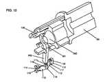
図1および図4を参照すると、ねじ35を駆動シャフト69に取り付け、それによって回転する。駆動シャフト69は概ね円筒形であり、内部ボア、軸方向で出力側に面する第1端、軸方向で入力側に面する第2端、および概ね一定の直径を有する。第1端では、駆動シャフト69を入力トルク装置、通常はモータからの歯車、スプロケットまたはクランクシャフトにしっかり取り付け、それによって回転する。駆動シャフト69は軸方向スプライン109を有し、これは第2端から延在して、ねじ35の内径に形成された対応するスプラインの組と係合して、これを回転する。駆動シャフトの中心傾斜路99の組は、概ね、第1側では駆動シャフト上に同軸で位置決めされた環状ディスク上にある1組の隆起傾斜表面駆動シャフト99のスプライン109と対合する対合爪を有し、駆動シャフト69によって回転して、駆動シャフト69に沿って軸方向に移動することができる。ピンリング195が駆動シャフト中心傾斜路99の第2側と接触する。ピンリング195は剛性リングで、アイドラ棒171上に同軸で位置決めされ、軸方向に動作可能であり、アイドラピン196をアイドラ棒171と位置合わせした状態で保持する機能を果たす横方向のボアを有する。アイドラピン196は細長い剛性の棒であり、ピンリング195の直径よりわずかに長く、アイドラ棒171の細長いスロット173を通して挿入され、ピンリング195のボアに挿入されると、その第1および第2端の両方でピンリング195のわずかに先まで延在する。アイドラ棒171の細長いスロット173によって、アイドラ棒171は、変速機100が1:1からハイへとシフトされると、ピン196に接触せずに図1で示すように見て右側へと軸方向に動作することができる。しかし、変速機100を1:1からローへとシフトすると、細長いスロット173の入力端の側がピン196と接触し、次にこれがピンリング195を介して駆動シャフト中心傾斜路99と動作自在に接触する。したがって、変速機が1:1とローの間にある場合、アイドラ棒171は駆動シャフト中心傾斜路99に動作自在に接続され、アイドラ棒171が軸方向に動作すると、駆動シャフト中心傾斜路99もアイドラ棒171との関連で軸方向に動作する。駆動シャフト中心傾斜路99の傾斜表面は、螺旋形、曲線状、直線状、または他の任意の形状でよく、対応する軸受けディスク中心傾斜路98の組と動作自在に接触する。軸受けディスク中心傾斜路98は、駆動シャフト中心傾斜路99と相補的で、それに対向する傾斜面を有する。変速機100の出力側に面する第1側では、軸受けディスク中心傾斜路98が駆動シャフト中心傾斜路99に面し、駆動シャフト中心傾斜路99と接触して、これに駆動される。 Referring to FIGS. 1 and 4, a
軸受けディスク中心傾斜路98は、変速機100の縦軸11の周囲で同軸上に回転するように位置決めされた概ね環状のディスクである軸受けディスク60にしっかり取り付けられる。軸受けディスク60は、軸受けディスクの軸受け66と接触する玉1に面していない側で、その周囲付近に軸受けの軌道輪を有する。軸受けディスクの軸受け66は、軸受けディスク60の周囲にある環状のスラスト軸受けであり、軸受けディスク60と入力ディスク34の間に位置決めされる。軸受けディスクの軸受け66は、軸受けディスク60に軸方向および半径方向の支持を提供し、変速機100の内部部品を部分的に封入するためにケース40とともに作用するケースキャップ67上の軸受け軌道輪によって支持される。 The bearing
図1を参照すると、ケースキャップ67は、駆動シャフト69から延在する概ね環状のディスクであり、周囲から、またはその付近から出力端へと延在する管状部分を有し、その中心を通るボアも有する。ケースキャップ67は、変速機100によって生成された軸方向および半径方向の力を吸収して、変速機100を密封し、それによって潤滑剤が逃げ、コンタミネーションの浸入を防止する。ケースキャップ67は静止状態であり、幾つかの実施形態では、従来の締結方法でケース40にしっかり取り付けるか、ケース40の内径にあって対応するメスねじと対合するオスねじを外径上に有することができる。上述したように、ケースキャップ67は軸受け軌道輪を有し、これはケースキャップ67からの管状延長部の出力端の内側に配置された軸受けディスク60の周囲付近で軸受けディスクの軸受け66と接触する。ケースキャップ67は、駆動シャフトの軸受け104と対合する環状部分の内径付近に配置された出力側に面する第2軸受け軌道輪も有する。駆動シャフト軸受け104は、スラスト軸受けとラジアル軸受けの組み合わせで、駆動シャフト69に軸方向および半径方向の支持を提供する。駆動シャフト67は、外径に形成されて、駆動シャフト軸受け104と対合する入力側に面する軸受け軌道輪を有し、これはねじ35によって生成された軸力をケースキャップ67に伝達する。入力軸受け105は、駆動シャフト69への支持を追加する。入力軸受け105は、駆動シャフト69上に同軸で位置決めされ、変速機100の入力側に面するケースキャップ67の内径上の第3軌道輪と対合する。入力軸受け105に軸受け面を提供するように設計された軸受け軌道輪を有する概ね円筒形のねじナットである円錐ナット106が、駆動シャフト69上にねじ込まれ、入力軸受け105を支持する。 Referring to FIG. 1, the
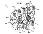
図1で示す実施形態を参照すると、概ね縦軸11の周囲のリングを形成する複数の周囲傾斜路61の組が、軸受けディスク60にしっかり取り付けられる。周囲傾斜路61は、縦軸11の周囲に半径方向に位置決めされた複数の傾斜表面であり、軸受けディスク60に対して位置決めされるか、その上に形成され、出力側に面する。傾斜表面は曲線、螺旋形、直線、または別の形状でよく、それぞれが複数の傾斜路軸受け62の1つに加える軸力を生成する楔を生成する。傾斜路軸受け62は球形であるが、円筒形、円錐形、または別の幾何学的形状でよく、軸受け保持器63に収容される。図示の実施形態の軸受け保持器63は概ねリング形であり、個々の傾斜路軸受け62を含む複数の開口を有する。入力ディスク傾斜路63の組は、入力ディスク34にしっかり取り付けられるか、その一部として形成される。幾つかの実施形態の入力ディスク傾斜路64は周囲傾斜路62に対して相補的であり、傾斜路は入力側に面する。別の実施形態では、入力ディスク傾斜路64は、傾斜路軸受け62と位置合わせして、これを半径方向にセンタリングする軸受け軌道輪の形態である。傾斜路軸受け62はトルクの変動に応答して、周囲傾斜路61および入力ディスク傾斜路64の傾斜面を上下に回転する。 Referring to the embodiment shown in FIG. 1, a set of
次に図1および図4を参照すると、軸力発生装置160は、入力ディスク34と玉1の間の垂直接触力を増加するために生成され、入力ディスク34に加えられる軸力を生成する様々な構成要素で構成され、これは玉1の回転に使用するために入力ディスク34と摩擦関係にある構成要素である。変換器100は、入力ディスク34、玉1および出力ディスク101が接触点で滑動しないか、許容可能な量しか滑動しないように、十分な軸力を生成する。変速機100に加えられるトルクの大きさが増大するにつれて、滑動を防止するために適切な量の追加軸力が必要である。さらに、ハイまたは1:1の速度比の場合よりローの方が、滑動を防止するために多くの軸力が必要である。しかし、ハイまたは1:1で提供する力が多すぎると、変換器100の寿命を短縮したり、効率を低下させたり、増加した軸力を吸収するために必要とされる構成要素が大型化したりする。理想的には、軸力発生装置160は、変速機100をシフトし、さらにトルクが変動するにつれて、玉1に加えられる軸力を変化させる。幾つかの実施形態では、変速機100はこの目標を両方とも達成する。ねじ35は、周囲傾斜路61が生成する軸力とは別個の異なる軸力を提供するように設計され、構成される。幾つかの実施形態では、ねじ35は周囲傾斜路61より小さい軸力を発生するが、他のタイプの変速機100では、ねじ35は周囲傾斜路61より大きい力を発生するように構成される。トルクが増加すると、ねじ35はわずかに多く回転してナット37に入り、トルクの増加に比例した量だけ軸力を増大させる。変速機100が1:1の比率であり、使用者または車両が低速へとシフトすると、アイドラ棒171がスリーブ19、スリーブ軸受け172、シフトガイド13a、13b、およびアイドラ18とともに入力側に向かって軸方向に動作する。アイドラ棒171は、ピン196およびピンリング195を通して駆動シャフト中心傾斜路99と接触し、これによって駆動シャフト中心傾斜路99が出力側に向かって軸方向に動作する。駆動シャフト中心傾斜路99の傾斜表面は、軸受けディスク中心傾斜路98の対向する傾斜表面と接触し、これによって軸受けディスク中心傾斜路98が軸受けディスク67を回転し、周囲傾斜路61を傾斜路軸受け62および入力ディスク傾斜路64と係合させる。駆動シャフト中心傾斜路99および軸受けディスク中心傾斜路98は、トルク分割機能を実行し、トルクの一部をねじ35から周囲傾斜路61へとシフトさせる。これは、周囲傾斜路61を通して配向される伝達トルクの割合を増加させ、上述したように周囲傾斜路61がトルクの影響を受けやすいので、発生する軸力の量が増加する。 Referring now to FIGS. 1 and 4, an
さらに図1および図4を参照すると、ローにシフトすると、アイドラ18が出力側に向かって軸方向に動作し、接触パッチ内の力の反応によってローへと引っ張られる。アイドラ18がローに向かって動作する量が多いほど、引く力が強くなる。接触部の垂直力およびシフト角度の増加とともに増加するこの「アイドラの引っ張り力」は、ハイへのシフト時にも発生する。アイドラの引きは、接触パッチに作用する横方向の力を補正するために発生し、この効果をスピンと呼ぶ。スピンは、3つの接触パッチ、つまり玉が入力ディスク34、出力ディスク101およびアイドラ18と接触する接触点で発生する。スピンの結果としてアイドラ18と玉1の間のティー アクトで生じる力の大きさは、玉1と入力
および出力ディスク34、101の場合と比較すると最小限である。アイドラ18と玉1の境界面の接触パッチで発生する最小限のスピンにより、この接触パッチが以下の説明では無視される。スピンは、入力ディスク34と玉1の、および出力ディスク101と玉1の接触パッチにおける効率損と見なすことができる。スピンは、玉1およびディスク34、101の回転方向に対して直角の横方向力を発生する。1:1の比率では、入力および出力接触パッチでスピンまたは接触スピンによって発生する横方向力が、等しく、反対方向であり、基本的に相殺される。この状態で、アイドラ18に軸方向の引っ張り力はない。しかし、変速機100を例えばローへとシフトすると、入力ディスク34および玉1の接触パッチは、玉1の軸線または極からさらに動作する。これはスピンを減少させ、さらに回転方向に対して直角に発生する横方向力も減少させる。同時に、出力ディスク101と玉1の接触パッチが、玉1の軸線または極へとさらに近づき、これはスピンおよびその結果の横方向力を増大させる。これは、変速機100の入力および出力側でスピンによって発生する横方向力が等しくない状況を生み出し、出力接触部にかかる横方向力の方が大きいので、出力ディスク101と玉1の間の接触パッチが、玉1の軸線にさらに近づく。変速機100をさらにローにシフトするほど、玉1に加えられる接触部の横方向の力が強力になる。玉1上にスピンによって引き起こされる横方向力は、ハイにシフトすると、反対方向の力を加える。玉軸3に取り付けた脚部2は、引っ張り力をシフトガイド13a、13bへと伝達し、シフトガイド13a、13bがアイドラ18およびスリーブ19に動作自在に取り付けられるので、軸力がアイドラ棒171に伝達される。接触部にわたる垂直力が増加するにつれ、全ての比率で接触スピンの影響が増大し、効率が低下する。With further reference to FIGS. 1 and 4, shifting low causes the idler 18 to move axially towards the output side and be pulled low by the reaction of the force in the contact patch. The more the idler 18 moves low, the stronger the pull. This "idler pull", which increases with increasing normal force and shift angle of the contact, also occurs when shifting to high. Idler pull occurs to compensate for lateral forces acting on the touch patch, and this effect is called spin. Spin occurs at the point of contact where the three contact patches, ie the balls, come in contact with the
さらに図1および図4を参照すると、変速機100をローにシフトするにつれて、アイドラ棒171に伝達される引っ張り力の結果、図1で見て左側に向かう軸力が生じ、このために入力トルクがねじ35から周囲傾斜路61へとシフトする。変速機100を極端なローにシフトするにつれ、アイドラ棒171がさらに強力に引っ張り、駆動シャフト中心傾斜路99と軸受けディスク中心傾斜路98との間に相対的動作を引き起こし、さらに多くのトルクを周囲傾斜路61へとシフトする。これは、ねじ35を通って伝達されるトルクを減少させて、周囲傾斜路61を通って伝達されるトルクを増加させ、その結果、軸力が増加する。 With further reference to FIGS. 1 and 4, as the
図1および図9を参照し、係合解除機構(以下で説明する幾つかの部品で構成される)について説明する。係合解除機構は、入力ディスク35と軸受けディスク60の間に配置され、出力回転数が入力回転数より大きい場合に変速機100を係合解除する。係合解除機構は複数の部品で構成され、入力ディスクコネクタ121を含み、これは周囲付近で入力ディスク34にしっかり取り付けた概ね円筒形の細長いピンであり、入力ディスク35から軸受けディスク60に向かって変速機100の縦軸11にほぼ平行な方向で突出する。入力ディスクコネクタ121は、第1端でクラッチレバー122と係合する。クラッチレバー122は剛性材料の概ねL字形の平坦な部片であり、短い脚部として延在する第1端、および長い脚部として延在する第2端を有し、脚部が交差する接合部からプレローダ123上で旋回する。入力ディスクコネクタ121とクラッチレバー122の第1端との係合は、滑動係合であり、これによって入力ディスクコネクタ121とクラッチレバー122との相対運動が可能になる。クラッチレバー122の接合部は、プレローダ123上に位置決めされた貫通穴によって形成される。123は可撓性の細長い棒であり、正方形、平坦、または任意の他の断面形状でもよく、一方端では軸受け保持器63を通って半径方向に延在する穴に取り付けられ、第2端では駆動シャフト69にしっかり取り付けられる。プレローダ123は、傾斜路軸受け62にバイアス付与して、周囲傾斜路61を上昇させることができ、係合解除機構を起動する間は、入力ディスク34を玉から引き離し、係合解除機構120の構成要素のような他の構成要素の取り付け手段として働くことができる。爪124もクラッチレバー122に取り付ける。爪124は概ね楔形であり、第1端では一点へと先細になり、第2端では丸まって、貫通穴がある。爪ピン125を、クラッチレバー122の第2端にある穴に挿入し、これによって爪124が爪ピン125の周囲で回転させながら、爪124をクラッチレバー122に取り付ける。爪124はディスク形のラチェット126と対合して、これと接触し、これは周囲に歯を有し、クラッチレバー122の背後で平坦になっている。ラチェット126の中心には穴があり、プレローダ123がこれを通ってクラッチレバー122に隣接し、変速機100の縦軸11へと半径方向内側に向かう。ラチェット126は、従来の締結具によって所定の位置に保持され、プレローダ123の周囲で回転可能である。ラチェットのベベル、つまり周囲に面取りした歯がある歯車を、ラチェット126にしっかり同軸で取り付けて、その一部にする。ラチェットベベル127の歯は傘歯車128と噛み合う。傘歯車128は、図示の実施形態では、軸受けディスク60にしっかり取り付けたリングであるが、駆動シャフト69および駆動シャフト中心傾斜路99のような他の回転構成要素に取り付けることができる。傘歯車128は、その周囲にラチェット126の歯と対合する歯を有する。主要ばね、つまり図11で示すように複数のコイルがあるコイルばねを、変速機100の縦軸11の周囲に同軸で位置決めし、その第1端を入力ディスク34へ、第2端を軸受けディスク60へ取り付ける。主要ばね129は、入力ディスク34にバイアス付与して、入力ディスク34が玉1と接触するように、ねじ35の周囲で回転させるか、そこから「ほどく」。 The disengagement mechanism (composed of several parts described below) will be described with reference to FIGS. 1 and 9. The disengagement mechanism is disposed between the
さらに図1および図9を参照すると、変速機100の入力回転が変速機100への入力回転が停止し、1つまたは複数の車輪、動力伝達系、または他の出力回転機構によって出力ディスク101が回転し続けると、玉1が出力ディスク101によって駆動される。次に、玉1が入力ディスク34を第1方向に回転して、ねじ35に「巻き付き」、玉1から係合解除する。入力ディスク34によって同じ第1方向に回転する入力ディスクコネクタ121が、クラッチレバー122に、および爪124にも接触して、これらを第1方向に回転する。爪124はバイアス付与されて、爪テンショナ(図示せず)によってラチェット126の歯と接触し、これは爪ピン125上に同軸で位置決めされたねじりばねでよい。爪124がラチェット126の歯の上を通過するにつれ、爪124がラチェット126の歯にロックされて、入力ディスク34がねじ35から第2方向にほどけるのを防止し、再び玉1と接触する。主要ばね129のバイアスがほどく傾向を有するからである。ラチェット126は、第2方向への回転を防止される。ラチェットのベベル127、つまりラチェット126の部品が、回転していない傘歯車128と連動する歯を有するからである。 With further reference to FIGS. 1 and 9, the input rotation of the
変速機100の入力回転が再開すると、傘歯車127が軸受けディスク60によって第1方向に回転し、これはラチェットベベル127およびラチェット126を第2方向に回転し、したがって爪124を第2方向に回転して、これによって主要ばね129が入力ディスク34にバイアス付与して、ねじ35から第2方向にほどき、玉1と接触することができる。入力ディスク34が第1方向に回転すると、第1端でプレローダ123に取り付けられた軸受け保持器63によって、プレローダ123が入力ディスク34に対して回転することに留意することが重要である。これは、入力ディスク34が第1方向に回転すると、傾斜路軸受け62が入力ディスク34に対して回転するからである。同様に、変速機100の入力回転が再開すると、軸受けディスク60が同じ相対的回転のためにプレローダ123に対して回転する。この動作は、係合解除機構120の係合および解放を提供する。 When the input rotation of the
図1および図15を参照すると、ラッチ115が入力ディスク34の側部にしっかり取り付けられ、これは軸受けディスク60に面して、フックレバー113の2つの端部のうち第1端にしっかり取り付けられたフック114と係合する。フックレバー113は、第1端にフック114があり、第2端にフック蝶番116がある細長い支柱である。ラッチ115は係合区域または開口を有し、これはフック114の幅より大きく、入力ディスク34および軸受けディスク60が相互に対して動作した場合に、ラッチ114の限界内で縦軸11に対してフック114が半径方向に動作するための余地を提供する。フック蝶番116は中央の蝶番119と係合し、第1蝶番ピン111と蝶番継ぎ手を形成する。中央蝶番119は、2つの端部を有する概ね細長い支柱である入力ディスクレバー112の第1端と一体である。入力ディスクレバー112は、その第2端に入力ディスク蝶番117を有し、これは第2蝶番ピン118の使用を介して蝶番ブレース10と係合する。蝶番ブレース110は概ね、フック114、フックレバー113、フック蝶番116、第1蝶番ピン111、中央蝶番119、入力ディスクレバー112、第2蝶番ピン118、および入力ディスク蝶番117を支持するベースであり、入力ディスク34に面する側の軸受けディスク60にしっかり取り付けられる。ラッチ115とフック114が係合すると、傾斜路軸受け62が、適正な量の軸力を駆動ディスク34に提供しない周囲傾斜路61上の区域へと回転することが防止される。この積極的係合は、周囲傾斜路61によって傾斜路軸受け62に加えられる回転力が全て、入力ディスク34に伝達されることを保証する。プレローダは第2端で入力ディスクレバー112に接触し、入力ディスク34にバイアス付与して玉1から離し、したがって入力ディスク34が玉1から係合解除すると、切り離した状態を維持するようにバイアス付与される。 Referring to FIGS. 1 and 15, a
図10を参照すると、変速機100の代替軸力発生装置の切り取り側面図が開示されている。単純にするために、前述した軸力発生装置と図10で示す軸力発生装置の差のみを提示する。図示の軸力発生装置は、1つまたは複数の逆転レバー261を含む。逆転レバー261は概ね平坦で不規則な形状のカム部片であり、それぞれが中心を外れて装着した旋回穴を有し、第1側が旋回穴の半径方向内側であり、第2側が旋回穴の半径方向外側である。逆転レバー261の第1側はそれぞれ、アイドラ棒171の細長いスロット173に填る。変速機200をローに向かってシフトすると、細長いスロット173の が逆転
レバー261の第1側と接触し、逆転レバー261が、逆転レバー261の旋回穴に挿入された逆転ピン262によって生成された軸で旋回する。第1側が細長いスロット173の端部と接触するにつれ、各逆転レバー261の第1側が変速機100の出力側に向かって動作し、逆転レバー261の第2側が変速機100の入力側に向かって動作して、それによって逆転レバー261のカム機能を満足する。第1側および第2側の長さを増減させることにより、入力側に向かって軸方向に動作する距離を減少させ、それが生成する力を増加させるように逆転レバー261を設計することができる。逆転レバー261をこの方法で設計して、これが発生する軸力を調節する機械的利点を生成することができる。逆転レバー261は、変速機100をローにシフトすると、その第2側でそれぞれねじ中心傾斜路298の出力側と接触する。逆転レバー261はそれぞれ、逆転ピン262によってレバーリング263に取り付けられ、逆転ピンは、レバーリング263の穴に押し込むか、ねじ込んで、逆転レバー261を所定の位置に保持することができる。レバーリング263はリング形の器具で、アイドラ棒171の周囲に填って、それに沿って軸方向に滑動し、逆転レバー261を挿入して位置決めできるように、自身を通して切り込まれた1つまたは複数の長方形のスロットを有する。Referring to FIG. 10, a cutaway side view of an alternative axial force generator for
さらに図10で示す実施形態を参照すると、1組のねじ中心傾斜路299がねじ35にしっかり取り付けられ、それによって回転することができる。この実施形態のねじ中心傾斜路299は、ねじ中心傾斜路299が、出力側に面する第1側および入力側に面する第2側を有するディスクの第2側にある傾斜路として形成されるという点で、図4で示すねじ中心傾斜路99と同様である。変速機100をローに向かってシフトするにつれ、逆転レバー261の第2側がねじ中心ランプ299の第1側に押し付けられる。上述したスプライン109を介して駆動シャフト69にスプライン接続されたねじ中心傾斜路299は、駆動シャフト69によって回転し、縦軸11に沿って軸方向運動が可能であり、以前の実施形態の駆動シャフト中心傾斜路99と同様であるが、ねじ中心傾斜路299は、出力側ではなくて変速機100の入力側に面する。ねじ中心傾斜路299は、軸受けディスク中心傾斜路298の対向する組と接触し、これは駆動シャフト69に対して自由に回転し、図4で示す軸受けディスク中心傾斜路98と同様であるが、軸受けディスク中心傾斜路298は、入力側ではなくて変速機100の出力側に面する。ねじ中心傾斜路299が逆転レバー261によって軸受けディスク中心傾斜路298に向かって軸方向に押されるにつれ、ねじ中心傾斜路299と軸受けディスク中心傾斜路298の傾斜路面の相対的回転が生じ、これによって軸受けディスク60は、周囲傾斜路61が係合するような点まで回転し、これによってトルクが周囲傾斜路61へとシフトし、発生する軸力の量が増加する。 Still referring to the embodiment shown in FIG. 10, a set of screw center ramps 299 are rigidly attached to the
次に図11を参照すると、図1の変速機100の代替実施形態の切り取り側面図が開示されている。単純にするために、以前の変速機100とこの変速機300との間の違いのみについて説明する。変速機300は代替保持器389、代替係合解除機構(図13および図14の項目320)、および代替軸力発生装置を有する。さらに、図11で示す実施形態では、螺旋型ばね133が変速機300の出力側へと動作し、シフトにハイ方向のバイアスを付与する。 Referring now to FIG. 11, a cutaway side view of an alternative embodiment of the
次に図11および図12を参照すると、代替保持器389が開示されている。保持器389は入力および出力固定子ディスク381a、381bを含むが、見やすくするために、出力固定子ディスク381bが除去されている。多くの実施形態の出力固定子381bは、入力固定子381aと構造的に類似している。複数の固定子曲線382が固定子ディスク381a、381bに取り付けられて、玉1に面している第1側および玉1に面していない第2側を有する。固定子曲線382のそれぞれの第2側391は、固定子ディスク181a、181bのそれぞれ一方に平らに置かれた平坦な表面である。固定子曲線382は、固定子曲線382を従来の締結具または他のタイプの取り付け機構で固定子ディスク381a、381bに取り付けるために使用する2つの貫通穴を有する。固定子曲線382は、その第1側それぞれに長方形のスロットを有し、それに複数の平坦なスペーサ383を挿入して、固定子381に接続する。平坦なスペーサ383は、固定子381間の距離を設定し、固定子381間に強力な接続を生成して、固定子381が平行かつ位置合わせされていることを保証する働きをする。 Referring now to FIGS. 11 and 12, an
図示の設計は、ほぼ平坦である固定子ディスク181を組み込む。したがって、固定子ディスク181は、ほぼ平坦な合成材料のシートを使用して製造することができる。固定子ディスク181は、型抜き、精密打ち抜き、または産業で知られている他のこのような技術のような幾つかの安価な製造技術のいずれかで生産することができる。この設計の固定子ディスク181は、薄いまたはシート状の金属、プラスチック、セラミック、木材または紙製品、または任意の他の材料から作成することができる。図示の設計によって、他の方法では比較的高価な構成要素の材料および製造の費用を、適切に高い公差まで大幅に削減することができる。 The illustrated design incorporates a stator disk 181 that is substantially flat. Thus, the stator disc 181 can be manufactured using a substantially flat sheet of synthetic material. The stator disc 181 can be produced by any of several inexpensive manufacturing techniques, such as die cutting, precision stamping, or other such techniques known in the industry. The stator disc 181 of this design can be made from thin or sheet metal, plastic, ceramic, wood or paper products, or any other material. The illustrated design allows the cost of material and manufacturing of otherwise expensive components to be significantly reduced to appropriately high tolerances.
次に図11、図13および図14を参照すると、代替係合解除機構320が開示されている。図13は、変速機300の軸付近から見た切り取り略図であり、図14は、変速機300の上および外側から概ね中心に向かって半径方向内側を見た切り取り略図である。前述した実施形態のラチェット126およびラチェットベベル127は、この実施形態では1つの爪歯車326に統合され、これは爪124と係合して、傘歯車328と連動する歯を有する。他の実施形態の傘歯車328は、傘歯車以外の歯を有してよい。クラッチレバー322は、3つ以上の穴を有する剛性の平坦なL字形構成要素である。「L」字形を形成する2本の脚部の接合部にある真ん中の穴は、クラッチレバー322をプレローダ123の周囲に回転自在かつ同軸で位置決めする。クラッチレバー322の長い脚部の端部に近い穴によって、爪ピン125を挿入して、爪124に取り付けることができる。入力ディスクコネクタ321と対合するクラッチレバー322の短い脚部の端部に近い穴は、入力ディスクコネクタ321のスロットに填るクラッチピン329を受け、これを保持する。入力ディスクコネクタ321は、入力ディスク34にしっかり取り付けられ、クラッチピン329の滑動係合を提供するスロットを有する。代替係合解除機構320の動作は、それ以外は前述して図1および図9で示した惰力運転機構120と同じである。 Referring now to FIGS. 11, 13 and 14, an alternative disengagement mechanism 320 is disclosed. FIG. 13 is a cutaway view looking from near the axis of the
次に図11および図15を参照すると、代替軸力発生装置は概ね円錐形の楔360を含み、これは変速機300の縦軸に沿って位置決めされ、軸方向に運動可能である。円錐楔360はスプライン109にも対合する。変速機300をローにシフトすると、円錐楔360がアイドラ棒171と係合し、アイドラ棒171と同じ方向で軸方向に動作する。円錐楔360は、変速機300の軸線付近でAFG(軸力発生装置)レバー362の第1端と接触する。AFGレバー362は、円錐楔360と係合する第1半円形端を有する概ね細長い部品であり、縦軸11から入力ディスクレバー112と係合する第2端へと半径方向外側に延在する。AFGレバー361は、AFGレバー362が回転する中心となる支点ピン361にてスプライン109に取り付けられる。支点ピン361はAFGレバー362の旋回を提供し、したがってAFGレバー362の第2端が入力ディスクレバー112と係合する。入力ディスクレバー112は、軸受けディスク60に動作自在に取り付けられて、軸受けディスク60を回転し、したがって周囲傾斜路61が係合し、入力トルクをねじ35から周囲傾斜路61へとシフトさせる。代替軸力発生装置360の動作は、それ以外は前述され、図1および図4に見られる軸力発生装置と同じである。 Referring now to FIGS. 11 and 15, an alternative axial force generator includes a generally
次に図16および図17を参照すると、図1の変速機100の代替実施形態が開示されている。単純にするために、図17の変速機1700と図1の変速機100との違いのみを説明する。図1の変速機100は1つの変動装置を含み、変動装置という用語は、出力速度に対する入力速度の比率を変化させる変速機100の構成要素を説明するために使用することができる。この実施形態の変動装置401を備えるアセンブリおよび構成要素は、図5の玉/脚部アセンブリ403、図4の入力ディスク34、出力ディスク101、アイドラアセンブリ402、および図7の保持器89を含む。変動装置401の全ての構成要素およびアセンブリは、変速機1700の特定の用途に最適に適合するように変化させることができ、図16では変動装置401を備えるアセンブリおよび構成要素の一般的形態が図示されている。 Referring now to FIGS. 16 and 17, an alternative embodiment of the
図17で示す変速機1700の実施形態は、変速機100と同様であるが、2つの変動装置401を含む。この構成は、直径または全体のサイズが小さい変速機1700で高いトルク能力が必要である用途に有益である。この構成は、軸受けディスク114および出力ディスク101を支持するために必要なラジアル軸受けも省略し、それによって全体的効率を向上させる。変速機1700は2つの変動装置401を使用することから、各変動装置401は出力側を有し、変速機1700も出力側を有する。したがって、3つの出力側があり、この構成では入力側と出力側を区別する「a」および「b」を有する規約またはマークのような要素を使用しない。しかし、図17におけるように入力側は右側になり、出力は左側になる。 The embodiment of the
図17から図19を参照すると、変速機1700を囲み、封入するケース423が図示されている。ケース423は概ね円筒形であり、変速機170を外部の自然力および汚染から保護し、適切な作動のために追加的に潤滑剤を含む。ケース423は、ケースの穴424を通って適合する標準的締結具(図示せず)でエンジン、枠、または他の剛性本体(図示せず)に取り付けられる。ケース423は入力側、つまりケースの穴424がある側または図示の右側が開放して、入力トルクを受け入れる。入力トルクは、外部の発生源から入力シャフト425へと伝達され、これはトルクを伝達可能な長く剛性の棒またはシャフトである。入力シャフト425は、スプライン、キーまたは他のこのような方法を介してトルクを軸受けディスク428に伝達する。軸受けディスク428は、変速機1700が発生した有意の軸力を吸収可能なディスク形の剛性構成要素である。設計が図1に示す軸受けディスク60に類似する。入力シャフト軸受け426は、入力シャフト425の入力端にあるフランジ429と軸受けディスク428との間で入力シャフト425上に同軸で位置決めされ、これによって軸受けディスク428と入力シャフト425の間に少量の相対運動が可能になる。軸受けディスク429が回転を開始すると、周囲傾斜路61、傾斜路軸受け62、軸受け保持器63、入力ディスク傾斜路64、および入力ディスク34が前述のように回転する。これは、入力側にある変動装置である第1変動装置420内の玉1を回転させる。 Referring to FIGS. 17-19, a
同時に、入力シャフト425が回転するにつれ、第2入力ディスク431が回転する。第2入力ディスク431は入力シャフト425にしっかり取り付けられ、裏当てナットで固定するか、入力シャフト425に押し付けるか、溶接、ピン留め、または他の方法で取り付けることができる。第2入力ディスク431が、軸受けディスク428の反対側で変速機1700の出力側に配置される。第2入力ディスク431および軸受けディスク428は、周囲傾斜路61、傾斜路軸受け62、および入力ディスク傾斜路64によって生成された大きい軸力を吸収し、これは前述したように、玉/ディスク接触パッチにおける滑りを防止する垂直力として作用する。第2入力ディスク431は、前述した入力ディスク34と形状が類似し、入力シャフト425を回転すると、これは第2変動装置422内の玉1を回転する。第2変動装置422は概ね第1変動装置420の鏡像であり、変速機1700の入力側からさらに離れて位置決めされ、したがって第1変動装置420はそれと入力側との間に位置する。 At the same time, as the
前述したように、第1変動装置420内の玉1は、出力ディ数430との回転接触を通してこの構成要素を回転させる。出力ディスク430は、前述した出力ディスク101と同じ機能を果たすが、2つの対向する接触表面を有し、両方の変動装置420、422の玉1と接触する。図17で示す断面図から、出力ディスク430は浅いアーチまたは逆さまの浅い「V」字形に成形することができ、その端部は2つの変動装置420、422の玉1と接触する接触表面を有する。出力ディスク430は第2変動装置422を囲み、概ね円筒形の形状で出力側に向かって延在する。図示の実施形態では、出力ディスク430の円筒形の形状が変速機1700の出力側に向かって継続して、第2入力ディスク431を囲み、その後に出力ディスク430の直径が減少して、ケース423を出るにつれて、これより小さい直径で概ね円筒形の形状に再びなる。出力ディスク430を同心円で保持し、これを第1および第2入力ディスク34、431と位置合わせするには、環状軸受け434、435を使用して、出力ディスク431と半径方向に位置合わせすることができる。ケース軸受け434がケースのボア内で出力ディスク430上に位置決めされ、出力ディスク軸受け435が出力ディスク430のボア内で出力シャフト425上に位置決めされて、図示の出力ディスク430を形成する。出力ディスク430は、相互に接続して図示の出力ディスク430を形成する2つの部片で作成することができる。これによって出力ディスク430の円筒形シェルの内側に第2変動装置422を組み付けることができる。 As mentioned above, the
図17で示すように、これは、出力ディスク430の大きい直径に沿って2つの環状フランジを使用することによって実行することができる。幾つかの実施形態では、環状フランジを、出力ディスク430の大きい直径に沿ってほぼ中間に配置する。次に図17、図20および図21を参照すると、変速機1700の玉軸433は、前述した玉軸3と同様であり、同じ機能を果たす。また、玉軸433は、玉1を傾斜させて変速機1700の速度比率を変化させる機構として働く。玉軸433は、個々の出力側それぞれが細長く、出力固定子435の壁を通して延在する。出力固定子435は前述した出力固定子80bと同様であるが、複数の放射状溝436が出力固定子435の壁の端から端まで通る。出力固定子435の溝436は、出力固定子435の端から端まで続き、したがって一連の等間隔の放射状溝436が出力固定子435の中心にあるボア付近から周囲まで放射状に延在する。玉軸433は、細長い出力端上に同軸で位置決めされたアイリスローラ407を有する。アイリスローラ407は概ね円筒形のホィールであり、玉軸433上で回転可能であり、アイリスプレート409の溝411内に填るように設計される。アイリスプレート409は環状ディスクまたはプレートで、その中心をボアが通り、これは変速機1700の縦軸11の周囲に同軸で適合する。アイリスプレート409は、各アイリスローラ407の厚さの2倍より大きい厚さで、ボア付近からアイリスプレート409の周囲付近まで放射状に外側へと延在する。アイリス溝411が放射状に延在するので、その角度位置も変化し、したがってアイリスプレート409が縦軸11の周囲で角度回転するにつれ、アイリス溝411は個々の長さに沿ってカム機能を提供する。つまり、溝411はアイリスプレート409の中心にあるボア付近から周囲付近の個々の点まで螺旋状になる。 This can be done by using two annular flanges along the large diameter of the
アイリスローラ407は、外側のアメーターに沿って丸みを付けるか、外隅に隅肉を有し、したがって玉軸433が傾斜しても、その直径はアイリスプレート409の溝411の内側で変化しないままである。アイリスプレート409は、全てのシフト比で両方の変動装置420、422からのアイリスローラ407がアイリスプレート433の溝411内に留まることができるのに十分なだけの厚さである。このアイリス溝411は、従来のアイリスプレートの方法で作動し、これによって玉軸433は、アイリスプレート409の回転時に半径方向内側または外側へと動作する。アイリスプレート409は、第1変動装置に面する第1側および第2変動装置に面する第2側を有し、変速機1700の縦軸11の周囲で、2つの出力固定子435上の突き合わせボス上、つまり出力固定から延在する管状延長部上に同軸で位置決めされる。2つの出力固定子435は、従来の締結具で、出力固定子435のボスの軸方向穴(図示せず)を通して相互に取り付けることができる。出力固定子435のボスは、その中心を通る1つの穴、および中心から外側へと放射状に位置決めされた複数の穴を有する。幾つかの実施形態では、出力固定子435上のボスが、アイリスプレート409よりわずかに広いスペースを形成して、アイリスプレート433に回転の自由を提供し、幾つかの実施形態は、ボスとアイリスプレート409の間で軸受けを使用し、出力固定子435間でアイリスプレート409の位置を正確に制御する。アイリスケーブル406は、アイリスプレート409の外径付近でアイリスプレート409の第1側に取り付けられて、接続点から長手方向に延在する。アイリスケーブル406は、第1変動装置420の出力固定子435を通して、引っ張られるとアイリスプレート409を回転するような方向に経路指示される。アイリスケーブル406は、出力固定子435の周囲付近の開口を通過した後、ケース423を通って変速機1700の外側へと経路指示され、そこで伝達比を制御することができる。アイリスばね408は、外径付近でアイリスプレート409の第2側に取り付けられる。アイリスばね408は、第2変動装置422の出力固定子435にも取り付けられる。アイリスばね408は弾性力を提供し、これはアイリスプレートがアイリスケーブル406の加える張力によって回転するのを防止する。アイリスケーブル406からの張力が解放されると、アイリスばね408はアイリスプレート409を休止位置へと復帰させる。変速機1700の用途に応じて、アイリスプレート409は、アイリスケーブル406を引くとアイリスプレート409が変速機1700をシフトして伝達比を上げ、アイリスケーブル406への張力が解放されると、アイリスばね408が変速機1700を低い比率へとシフトするように構成することができる。あるいは、アイリスプレート409は、アイリスケーブル406を引くとアイリスプレート409が変速機を低い方の比率にシフトし、アイリスケーブル406への張力が解放されると、アイリスばね408が変速機1700を高い比率にシフトするように構成することができる。 The
図16および図17を参照すると、2つの変動装置420、422を有する変速機1700の実施形態は、変速機1700の追加の回転要素の位置合わせに高度の精度を必要とする。全ての回転要素は、相互と位置合わせしなければならない。さもないと効率が低下し、変速機1700の寿命が短縮される。組立中に、入力ディスク34、出力ディスク430、第2入力ディスク431、およびアイドラアセンブリ402は、同じ縦軸上で位置合わせされる。また、保持器410は、これらの実施形態では前述したように出力固定子435によって接合された2つの保持器89で構成され、これも玉/脚部アセンブリ403を正確に位置決めするために、縦軸にも位置合わせしなければならない。これを単純かつ正確に実行するために、全ての回転要素は入力シフト425に対して位置決めされる。第1入力固定子軸受け440および第2入力固定子軸受け444は、入力固定子440、444のボア内、および入力シャフト425上に位置決めされて、保持器410の位置決めを補助する。出力固定子軸受け422ポジションe8Xt he出力固定子435のボ
アおよび入力シャフト425上も、保持器410を位置決めする。第1案内軸受け441は、第1シフトガイド13bのボア内、および入力シャフト425上に位置決めされ、第2案内軸受け443は、第2シフトガイドのボア内、および入力シャフト425上に位置決めされて、第1および第2アイドラアセンブリ402を位置決めする。Referring to FIGS. 16 and 17, the embodiment of
図18および図19を参照すると、保持器410は、ケースのスロット421内に填る前述のケースコネクタ383でケース423に取り付けられる。ケーススロット421はケース423内の長手方向の溝であり、ケース423の入力側、つまりケース423の開放側に延在する。図示の実施形態では、ケースは図19に図示されていない出力側でほぼ閉鎖しているが、入力側では開放し、ケース423のこれ以外は円筒形の本体から半径方向に延在する装着フランジを有し、これはケース423を装着するための穴424がある。組立中に、変速機170はケース423に挿入可能であり、ケースコネクタ383は、ケージ410に加えられるトルクに抵抗して、ケージ410の回転を防止するために、ケースのスロット421内に位置合わせされる。ケース423のケースコネクタ穴412によって、締結具をケースコネクタ383内の対応する穴に挿入して、保持器410をケース423に締結することができる。 Referring to FIGS. 18 and 19, the holder 410 is attached to the
図22は、変速機1700の保持器470の代替実施形態を示す。製造費を削減するために、製造される異なる部品の数を最小限に抑えて、大量生産技術を使用して安価に生産できる部品を設計することが好ましいことがある。図示の保持器470は、低コスト設計の4つの異なる部品、および様々な構成要素を組み付ける締結具を使用する。固定子472は概ね平坦なディスク形の部片であり、複数の方砂上の溝が、回転する入力シャフト425が通る中心のボア付近から外側へと放射状に延在する。玉軸(図17の項目433)は、固定子472の溝を通って延在する。固定子472の中心ボアを囲む複数の穴471は、固定子472を他の構成要素に締結する。4つの固定子472があり、これはこの実施形態では、全て相互に類似し、保持器470の部分を形成する。2つの入力固定子472が保持器470の各端にあり、2つの出力固定子472が保持器472の中心付近にあって、固定子ブリッジ477で相互にしっかり取り付けられる。 FIG. 22 shows an alternative embodiment of the
さらに図22に示す実施形態を参照すると、固定子ブリッジ477はディスク形の部品であり、中心ボアおよび貫通穴が固定子ブリッジ477の内径と外径の間に地決めされる。固定子ブリッジ477の穴は、固定子472の穴と相補的であり、これによって固定子472を固定子ブリッジ477に締結することができる。アイリスプレート409(図示せず)が、固定子ブリッジ477の半径方向外側で、軸方向には出力固定子472の間に配置される。幾つかの実施形態では、固定子ブリッジ477はアイリスプレート409よりわずかに厚く、それによってアイリスプレート409の回転の自由が可能になるが、さらに他の実施形態では、軸受けが出力固定子472とアイリスプレート409の間、さらに固定子ブリッジ477とアイリスプレート409の間に配置される。したがって、固定子ブリッジ477の外径は、アイリスプレート409の内径を配置し、その軸線を設定する働きをする。 Still referring to the embodiment shown in FIG. 22, the
スペーサ473が入力固定子472を出力固定子472に接合する。1つの実施形態では、スペーサ473が、シートまたはプレート状の金属のような平坦な材料から作成されて、幾つかの目的を果たす一意の形状を生成するように形成される。スペーサ473は、概して平坦な長方形のシートであり、中心に形成された穴475があり、各端に直角の延長部を有する。スペーサ473は、固定子472間に正確な距離を設定し、保持器470に構造的フレームを形成して、玉1が変速機1700の縦軸を周回するのを防止し、固定子472の中心が位置合わせされて、固定子472の角度方向が穴時であるように、相互に対して位置合わせし、保持器470の捻れまたは上ぞりを防止し、回転する固定子ホィール30が載る凹状回転表面479を提供する。各スペーサ473には、面からの2つの端に屈曲部が形成され、スペーサの残りの部分は、保持器470の装着区域480および湾曲表面479を形成する。スペーサ473は、固定子472と接触する側に装着穴481を有し、これは固定子472の対応する穴と整列して、スペーサ473を固定子472に締結できるようにする。スペーサ473の中心付近の穴475は、玉1にクリアランスを提供する。 A
1つの実施形態では、玉1ごとに2つのスペーサ473があるが、異なる数のスペーサ473を使用することができる。各スペーサ473は、鏡像で相互と背中合わせの対になり、I形鋼の形状を形成する。1つの実施形態では、リベット476を使用して、スペーサ473を固定子472に接続し、固定子472を固定子ブリッジ477に接続することができる。リベット476は、組立中に、固定子472、スペーサ473および固定子ブリッジ477の穴にしっかり押し込まれる。図22には2つのリベット476しか図示されていないが、全部が同じ設計を使用することができる。第1変動装置420に使用するスペーサ473もケースコネクタ474を有し、これは概ねスペーサ473から外側へと放射状に延在し、次に概ね直角に屈曲する。幾つかの実施形態のケースコネクタ474は、シート状金属のような平坦な材料から作成され、これを型抜きしてから、最終的形状に形成する。ケースコネクタ474は、スペーサ473と一体で作成するか、しっかり取り付け、入力ディスク34と出力ディスク430の間でケース423へと放射状に延在することができる。幾つかの実施形態では、ケースコネクタ474はスペーサ473の製造プロセス中にスペーサ473の部品として形成する。ケースコネクタ474の直角の端部にあるケースコネクタ穴478は、対向するケースコネクタ穴(図19の項目412)と整列し、したがって保持区470を標準的な締結具でケース423に係留することができる。 In one embodiment, there are two
図22で示す設計は固定子ディスク472を組み込み、これはほぼ平坦であり、ほぼ平坦な剛性材料のシートを使用して製造することができる。また、ケースコネクタ474付きおよびなしのスペーサ473もほぼ平太であり、平坦な材料のシートから形成可能であるが、多くの実施形態では、ケースコネクタ474の直角の端部、装着区域480および湾曲表面480は、その後の屈曲ステップで形成する。固定子ディスク472およびスペーサは、型抜き、精密打ち抜き、または産業で知られている他のこのような技術など、任意の数の安価な製造技術で生産することができる。この設計の固定子ディスク472およびスペーサ473は、薄いまたはシート状の金属、プラスチック、セラミック、木材または紙製品または任意の他の材料から作成することができる。図12に関して上述したように、図示の設計によって、これ以外の方法では比較的高価な構成要素の材料および製造の費用を、適切に高い公差まで大幅に削減することができる。また、図22に示す実施形態は変速機の二重空隙の設計を表すが、これらのXse製造プロセスで製造した構成要素は、保持器470の単一空隙の設計にも同様に使用することができる。一例として、図示の2つの固定子ディスク472を、図22の右側にあるケースコネクタ474を有するスペーサ473に取り付けて、本明細書に記載された実施形態で使用する単一空隙の設計を生産することができる。 The design shown in FIG. 22 incorporates a
図23は、図1および図17の変速機100、1700で使用する玉1の実施形態を示す。玉1は、玉1を通して潤滑剤を給送する螺旋溝450を有する。1つの実施形態では、2つの螺旋溝450を使用し、これは玉1の穴の一方端で開始して、穴の他方端まで続く。螺旋溝450は、変速機100、1700の効率を向上させ、寿命を改善するために、玉1を通して潤滑剤を移送し、熱を除去して、玉1と玉軸3、433の間を潤滑する。 Figure 23 shows an embodiment of a
図24は、図5の玉/脚部アセンブリ403の代替脚部460を示す。脚部460は、図5で示した脚部2と比較すると単純化され、固定子ホィール30、固定子ホィールピン31、案内ホィール21、または案内ホィールピン22がない。脚部460は、玉1に面していない第1脚部側463に凸状表面を有し、これは個々の固定子80の対応する凹状溝(図示せず)に適合する。玉1の面する第2脚部側465では、脚部460は凹状になり、半径方向内側の端部付近には、脚部カム466を形成する凸状曲線を有し、これはシフトガイド13の表面に接触し、それによって軸方向および半径方向に位置決めされる。横方向および長手方向の潤滑部品462、464はそれぞれ、潤滑剤が脚部に供給され、様々な区域に移送されるようにする。潤滑は、変速機100、1700の脚部および他の部品を冷却し、さらに脚部がシフトガイド13および固定子80に接触する場所の摩擦を最小限に抑えるために使用される。脚部460に追加の口を穿孔するか、形成して、潤滑剤を他の区域に配向することができ、任意の開口を潤滑剤の入口として使用してよいことに留意されたい。長手方向の口464は、脚部460の長さを通る口であり、概ね中心にあり、底部を通り、各脚部460の頂部で玉軸ボア461も通って延在する。横方向の口462は、長手方向の口464に対してほぼ直角に形成された盲穴であり、第1脚部側463から出て、その先まで延在する。幾つかの実施形態では、図示のように横方向の口462が長手方向の口464と交差し、第2脚部側465で終了し、それに貫入しない。横方向の口462が長手方向の口464と交差する幾つかの実施形態では、潤滑剤が横方向の口462の開口に入り、次に朽ち464を通って移送されることが可能である。 FIG. 24 shows an
幾つかの実施形態では、玉軸3、433を玉1に圧入し、玉1で回転させる。玉軸3、433は、玉軸ボア461内およびローラ4内で回転する。潤滑剤は脚部460の頂部を通って軸ボア461に流入し、ここで流体層を提供して、摩擦を軽減する。 In some embodiments,
図25から図27を参照すると、シフトガイド13上の凸状曲線97を近似するグラフでの方法が開示されている。単純にするために、アイドラ18、アイドラ軸受け17、およびシフトガイド13を組み合わせて、シフトガイド13の一実施形態の正確な凸状曲線97の分析および図示を単純化する。この分析および説明のために、以下のように仮定する。 Referring to FIGS. 25-27, a graphical method is disclosed which approximates the
1.玉1の中心は、玉1がその軸線の周囲で回転でき、その軸線が回転できるが、玉1は変位できないように固定される。1. The center of the
2.玉1、玉軸3、433、脚部2および案内ホィール21は剛性本体として回転する。2. The
3.アイドラ18は、x方向でのみ動作することができる。3. The idler 18 can only operate in the x-direction.
4.アイドラ18の周囲表面は、玉1の周囲に対して垂直である。4. The peripheral surface of idler 18 is perpendicular to the periphery of
5.シフトガイド13の側部は、案内ホィール21の周囲に対して垂直である。5. The side of the
6.玉1の角回転は、シフトガイド13の直線運動を引き起こし、その逆もある。6. The angular rotation of the
7.玉軸3、433が水平または縦軸11に平行である場合、各案内ホィール21とその個々のシフトガイド13との接触点は、シフトガイド13の垂直壁が凸状曲線97へと遷移する凸状曲線97の開始点にある。7. When the
玉1を傾斜すると、案内ホィール21は1つのみが凸状曲線97に接触し、他の案内ホィール21は、シフトガイド13の垂直壁と接触する。 When the
この分析の目的は、玉1の軸の傾斜角度の関数として、案内ホィール21がシフトガイド13上の凸状曲線97と接触する点のおおよその座標を発見することである。これらの座標を様々な玉軸3、433の角度についてプロットすると、曲線は、案内ホィール21/シフトガイド13の接触点の路をシフト範囲全体にわたって通る座標点に当てはめることができる。 The purpose of this analysis is to find the approximate coordinates of the point at which the
座標は、回転角度がゼロである案内ホィール21/シフトガイド13の接触の起点(x0、y0)で開始し、次に玉1の傾斜中に各増分で角度変化する。これらの座標を比較することにより、玉1の傾斜の関数(θ)として案内ホィール21/シフトガイド13の接触位置(xn、yn)を求めることができる。 The coordinates start at the contact origin (x0, y0) of the
図25および図26から、既知の変数は以下の通りである。 Known variables from FIG. 25 and FIG. 26 are as follows.
1.H1:玉1の中心から案内ホィール21の中心までの垂直距離。1. H1: Vertical distance from the center of the
2.H2:玉1の半径とアイドラ18の半径との合計。2. H2: Sum of radius of
3.W:玉1の中心から案内ホィール21の中心までの水平距離。3. W: Horizontal distance from the center of the
4.rw:案内ホィール21の半径。4. rw: radius of the guiding
これらの既知の変数から、以下の関係式を識別することができる。 From these known variables, the following relationship can be identified:
R1=[(W−rw)2+H12]^(1/2) (1)
Phi=TAN−1[(W−rw)/H1] (2)
xo=W−rw (3)
yo=H1−H2 (4)
BETA=TAN−1(H1/W) (5)
R2=[H12+W2]^(1/2) (6)
ここで、シフトガイド13をx方向に動作させる角度θだけ玉1を傾斜させると仮定する(図26参照)。ここから、以下のことが分かる。R1 = [(W-rw) 2 + H12] ^ (1/2) (1)
Phi = TAN-1 [(W-rw) / H1] (2)
xo = W-rw (3)
yo = H1-H2 (4)
BETA = TAN-1 (H1 / W) (5)
R2 = [H12 + W2] ^ (1/2) (6)
Here, it is assumed that the
Nu=90°−BETA−THETA (7)
x2=R2*SIN(Nu) (8)
x3=x2−rw (9)
x_shift guide=xo−x3 (10)
これは、シフトガイド13が所与のθで動作するx距離である。Nu = 90 ° -BETA-THETA (7)
x2 = R2 * SIN (Nu) (8)
x3 = x2-rw (9)
x_shift guide = xo−x3 (10)
This is the x distance that the
x4=R1*SIN(Phi+THETA) (11)
x_guide wheel=x4−xo (12)
これは、案内ホィール21が所与のθで動作するx距離である。x4 = R1 * SIN (Phi + THETA) (11)
x_guide wheel = x4-xo (12)
This is the x distance at which the
ここで、アイドラ18の中心にx’−y’の起点を画定すると都合がよい。これは、案内ホィール21/シフトガイド13の接点の座標をプロットするために有用である。 Here, it is convenient to define the x'-y 'origin at the center of the idler 18. This is useful for plotting the coordinates of the contact points of the guiding
x1=xo−(x_shift guide−x−guide Wheel) (13)
等式(10)、(12)および(13)を組み合わせると、下式になる。x1 = xo- (x_shift guide-x-guide Wheel) (13)
Combining equations (10), (12) and (13) gives:
x1=x4+x3−xo (14)
これは、案内ホィール21/シフトガイド13の接点のx’位置である。x1 = x4 + x3-xo (14)
This is the x 'position of the contact point of the
案内ホィール21/シフトガイド13の接点のy’位置を見いだすのは、比較的単純である。 Finding the y 'position of the contact point of the guiding
y2=RI*COS(Phi+THETA) (15)
y1=H2−y2 (16)
これは、案内ホィール21/シフトガイド13の接点のy’位置である。y2 = RI * COS (Phi + THETA) (15)
y1 = H2-y2 (16)
This is the y 'position of the contact point of the
したがって、x1およびy1を求めて、次にθの様々な値についてプロットすることができる。これを図27のグラフで示す。座標を所定の位置にすると、大部分のCADプログラムでこれを通る曲線を当てはめるのは単純である。曲線の当てはめの方法は、このような関係の適切な曲線を求めるために、例えば線形回帰などの任意の適切なアルゴリズムを含むことができるが、上述した関係式から導出された一次関数も展開することができる。 Thus, x1 and y1 can be determined and then plotted for various values of θ. This is shown by the graph in FIG. With the coordinates in place, it is simple to fit a curve through it in most CAD programs. The method of curve fitting can include any suitable algorithm such as, for example, linear regression, in order to determine the appropriate curve of such a relationship, but also expands the linear function derived from the above-mentioned relationship be able to.
次に図1、図7および図28を参照すると、変速機100を連続可変遊星歯車装置500として使用することができる。図1および図7を参照すると、保持器89が縦軸11の周囲で自由に回転するこのような実施形態では、アイドラ18が太陽歯車として機能し、玉1が遊星歯車として作用して、保持器89が玉1を保持し、遊星枠として機能して、入力ディスク34が第1輪歯車であり、出力ディスク101が第2輪歯車である。各玉1が入力ディスク34、出力ディスク101およびアイドラ18と接触し、保持器89によって担持され、半径方向の位置を保持される。 Referring now to FIGS. 1, 7 and 28,
図28は、遊星歯車装置500の骨格図、つまり略図であり、単純にするために遊星歯車装置500の上半分のみが図示されている。図は、遊星歯車装置500の中心線で、つまり変速機100の縦軸11で切断されている。出力ディスク101によって各玉1の周囲に形成された接触線は、可変の回転直径を形成し、これによって各玉1のその部分が第1遊星歯車501として機能することができる。玉1とアイドラ18との接触は可変回転直径を生成し、これによって各玉1のその部分が第2遊星歯車502として機能することができる。玉1と入力ディスク34のとの接触は可変回転直径を生成し、これによって玉1のその部分が第3遊星歯車503として機能することができる。 FIG. 28 is a skeleton or schematic view of the planetary gear set 500 and only the upper half of the planetary gear set 500 is shown for simplicity. The figure is cut at the center line of the planetary gear set 500, that is, at the
遊星歯車装置500の実施形態では、様々なラジアル軸受けおよびスラスト軸受けを有利に使用して、入力ディスク34、出力ディスク101および保持器89の相互に対する位置を維持できることが当業者には認識される。当業者は、中実または中空のシャフトを使用するか、これを入力ディスク34、出力ディスク101、保持器89および/またはアイドラ18に適宜取り付けて、本明細書に記載された機能を果たすことができることも認識し、このような改造は回転動力伝達装置の当業者の技術に十分入る。 Those skilled in the art will appreciate that various embodiments of planetary gear set 500 may advantageously use various radial and thrust bearings to maintain the position of
次に図29から図31を参照すると、第1遊星歯車501、第2遊星歯車502および第3遊星歯車503の個々の直径は、変速機100をシフトして変更することができる。図29は、等しい直径の第1および第3遊星歯車501、503、および最大直径の第2遊星歯車502がある変速機100を示す。前述したように玉1を傾斜させると、遊星歯車501、502、503の直径が変化し、変速機1700の出力速度への入力を変化させる。図30は、第1遊星歯車501の直径が増加し、第2および第3遊星歯車502および503の直径が減少するように傾斜した玉1を示す。図31は、第3遊星歯車503の直径が増加し、第1および第2遊星歯車501および502の直径が減少するように傾斜した玉を示す。 Referring now to FIGS. 29-31, the individual diameters of the
入力ディスク34、アイドラ18および/または保持器89間のトルク源を変更することによって、多くの異なる速度の組み合わせが可能である。また、幾つかの実施形態は複数の入力を使用する。例えば、入力ディスク34および保持器89は両方とも入力トルクを提供し、同じ速度または異なる速度で回転することができる。1つまたは複数の入力トルク源が、可変速度を可能にし、変速機100に可能な比率を増加させる。変速機100を遊星歯車装置として使用することによって可能である組み合わせの幾つかのリストを以下に提供する。このリストでは、入力トルク源、つまり「入力」を「I」でコード化し、出力を「O」でコード化して、縦軸11の周囲で回転しないように固定した構成要素を「F」でコード化し、構成要素が自由に回転できる場合、それは、コード化されたh an
「R」である。1つの入力および1つの出力があることを示すには、「1入/1出」を使用し、2つの入力および1つの出力があることを示すには「2入/1出」を使用し、1つの入力および2つの出力があることを示すには「1入/2出」を使用し、2つの入力と2つの出力があることを示すには「2入/1出」を使用し、3つの入力および1つの出力があることを示すには「3入/1出」を使用し、1つの入力と3つの出力があることを示すには「1入/3出」を使用する。By varying the torque source between
It is "R". Use “1 in / 1 out” to indicate that there is one input and one output, and use “2 in / one out” to indicate that there are two inputs and one output Use "1 in / 2 out" to indicate that there is one input and two outputs, and use "2 in / 1 out" to indicate that there are two inputs and two outputs Use "3 in / 1 out" to indicate that there are 3 inputs and 1 output, and use "1 in / 3 out" to indicate that there is 1 input and 3 outputs .

図32を参照すると、変速機100は、平行な動力路を通して遊星歯車装置505と組み合わせて、さらに多くに速度の組み合わせを生成することもできる。典型的な遊星歯車装置505は、中心の太陽歯車、太陽歯車の周囲に分布して、それと係合し、全てが個々の中心で単純に枠とも呼ばれる遊星枠に回転自在に取り付けられる複数の遊星歯車、および遊星歯車を囲み、それと係合する輪歯車で構成される。入力トルクおよび出力の源を太陽歯車、枠および輪歯車の間で切り換えることにより、多くの速度の組み合わせを獲得することができる。変速機100と組み合わせた遊星歯車装置505は、非常に多数の速度組み合わせを提供し、場合によっては、無限に可変の変速機を獲得することができる。図32では、変速機100のトルク入力を入力ディスク34と第1歯車506の両方に結合し、これは入力ディスク34とほぼ同軸であり、第2歯車509と接触して、これを回転し、平行な動力路を駆動する。変速機100、つまりCVT100の入力ディスク34と平行動力路の入力との両方を、原動機またはモータまたは他の動力付与装置などの他のトルク源に結合する基本的構成とを「結合された入力部」と呼ぶ。第1歯車506および第2歯車509の直径を変化させることにより、平行動力路への入力速度を変化させることができる。第2歯車509は歯車シャフト508に取り付けられて、これを回転し、幾つかの実施形態では歯車箱507を回転する。このような実施形態では設計の選択肢として実現された歯車箱507は、平行動力路の回転速度をさらに変動させ、従来の歯車型変速機でもよい。歯車箱507は歯車箱シャフト511を回転し、これが第3歯車510を回転する。歯車箱507を使用しない実施形態では、歯車シャフト508が第3歯車510を駆動する。第3歯車510は遊星歯車装置505の太陽、枠、または輪を駆動し、所望の速度/トルク比を生成するように設計された直径である。あるいは、第3歯車510を省略し、歯車箱シャフト508が遊星歯車装置505の太陽、枠または輪を直接回転することができる。遊星歯車装置505は、CVT100の出力からの入力も有し、これは別の太陽、枠または輪を駆動する。 Referring to FIG. 32, the
「結合された入力部」と題した下表では、直前に記載されたような基本的配置構成で可能である様々な入力と出力の組み合わせの全てではないまでも多くを識別する。この表では、「IT」はCVT100への入力トルクの源を表し、「0」は遊星歯車装置505に結合したCVTの構成要素を表し、「I1」はCVT出力に結合された遊星歯車装置505の構成要素を表し、「OV」は車両または機械の出力部に接続された遊星歯車装置505の構成要素を表し、「F」は軸の周囲で回転しないように固定された遊星歯車装置505または変速機100の構成要素を表し、「I2」は第3歯車509である平行路に結合された構成要素を表し、「R」は軸の周囲で自由に回転し、したがって別の構成要素を駆動しない構成要素を表す。この表および「結合された出力」と題された以降の表では、本明細書で提供しなければならない表の全体数を減少させるために、輪歯車が、固定されている唯一の遊星歯車装置505の構成要素であるものと仮定する。太陽歯車または遊星枠も、他の構成要素の対応する入力と出力の組み合わせで固定することができ、これらの組み合わせは、この説明のサイズを削減するために本明細書では提供しないが、以下の2つの表に基づいて容易に決定される。 The table below entitled "Coupled Inputs" identifies many, if not all, of the various input and output combinations that are possible in the basic arrangement as just described. In this table, "IT" represents the source of input torque to
図33で示す実施形態を参照すると、トルク入力源は遊星歯車装置505を駆動し、これは入力部としてCVT100に結合される。CVTの1つまたは複数の構成要素が平行動力路に、および変速機の出力部に結合される。この実施形態の平行動力路は以下の通りである。つまり、太陽、枠、または輪のいずれかの遊星歯車装置505の構成要素が、第3歯車510と噛み合い、これが歯車シャフト508を回転して、これが前述した歯車箱507を駆動する。歯車箱507は歯車箱シャフト511を回転し、これが第2歯車509を回転して、これが第1歯車506を駆動する。次に、第1歯車が変速機の出力シャフトに装着され、これはCVT100の出力部にも結合される。この実施形態では、遊星歯車装置505は変速機のトルク現に結合され、平行路とCVT100の両方にトルクを提供し、これらの路の両方からのトルクは、車両または機器の出力部で結合される。したがって、遊星歯車装置505がCVT100にトルクを、平行路に固定した比率を提供するように結合され、両方の路が駆動シャフト、ホィール、または他の負荷を受けた装置のような出力部で結合する場合、その構成を「結合された出力部」と呼ぶことができる。この基本的構成では、CVT100と組み合わせた遊星歯車装置505が非常に多数の速度の組み合わせを提供し、場合によっては無限可変の変速機を獲得することができる。 Referring to the embodiment shown in FIG. 33, a torque input source drives a planetary gear set 505, which is coupled to
「結合された出力部」と題した下表では、図33で示した基本的配置構成で可能な組み合わせの全部ではないまでも多くが提供され、説明される。この表では、遊星歯車装置505の場合、「O1」はCVT100に結合した遊星歯車装置505の構成要素を指し、「I」はエンジン、人間または何らかの供給源からの入力を指し、「F」は自身の軸線の周囲で回転しないように固定された構成要素を指し、「O2」は遊星歯車装置510を介して平行路に結合された構成要素を指す。CVT100の場合、「I」は遊星歯車装置505に結合した構成要素を指し、「O」は車両または機械の出力部に結合された構成要素を指し、「F」は上述したように固定された構成要素を指し、「R」はその軸線の周囲で自由に回転し、したがって他の構成要素を駆動しない構成要素を指す。 In the table below entitled "Coupled Output", many, if not all, of the possible combinations of the basic arrangement shown in FIG. 33 are provided and described. In this table, for planetary gear set 505, "O1" refers to the component of planetary gear set 505 coupled to
図32で示す実施形態を参照すると、「入力結合2入力動力路」と題された下表は、基本的な入力結合構成と遊星歯車装置505への2つのトルク入力源の組み合わせを示す。この表の参照文字は、以前の表と同じ構成要素を表すが、遊星歯車装置505の場合、「I1」はCVT100の出力部を指し、「I2」はこの場合は遊星歯車510である平行路に結合した構成要素である。 Referring to the embodiment shown in FIG. 32, the following table entitled “Input Coupling 2-Input Power Path” shows the combination of the basic input coupling configuration and the two torque input sources to the planetary gear set 505. The reference letters in this table represent the same components as in the previous table, but in the case of planetary gear set 505, “I1” refers to the output of
さらに図32で示す実施形態を参照すると、「入力結合3入力」と題した下表は、CVTへの3つの入力トルク源を使用する実施形態を指す。この表では、CVT100の参照文字は、以前の表と同じ構成要素を指し、遊星歯車装置505の参照文字は、同じ構成要素を表すが、「I2」は平行路に結合した構成要素を表す。 Still referring to the embodiment shown in FIG. 32, the table below entitled "Input Coupling 3-Input" refers to an embodiment using three input torque sources to the CVT. In this table, the reference letters of
次に図34で示す実施形態を参照すると、本明細書に記載された実施形態の独特な配置構成のために、平行路を省略することができる。平行路は、ここでは組み合わせて同一線上の配置構成にすることができ、ここでCVTおよび遊星歯車装置505の様々な構成要素を結合して、上記および下記の全ての組み合わせを生成する。幾つかの実施形態では、遊星歯車装置505をCVT100の入力部に結合するか、図34で示すように、CVT100の出力部に結合することができる。「入力結合2出力動力路」と題した下表は、CVT100から遊星歯車装置505への2つの出力部がある場合に可能な様々な組み合わせを挙げている。CVTの参照文字は様々な表と尾内であり、遊星歯車装置500の参照文字は同じ構成要素を表すが、「I2」のみは平行路に結合されないで、CVT100の第2出力部に結合される。 Referring now to the embodiment shown in FIG. 34, parallel paths can be omitted due to the unique arrangement of the embodiments described herein. The parallel paths can be combined here into a collinear arrangement where the various components of the CVT and planetary gear set 505 are combined to produce all the combinations described above and below. In some embodiments, planetary gear set 505 may be coupled to the input of
以前の2つの表では、記載された変速機を逆転して、各組み合わせで反対の結果を提供することができるが、このような反対の組み合わせは容易に認識されるので、スペースを考慮して本明細書では別個に説明しない。例えば、出力結合2出力、つまり入力結合/2入力の逆の場合、遊星歯車装置505の入力のいずれかをCVT100出力部のいずれかに結合することができる。 In the previous two tables, the described transmission can be reversed to provide the opposite result in each combination, but such opposite combinations are easily recognized so space considerations Not separately described herein. For example, in the case of output coupled two outputs, ie, the inverse of input coupled / two inputs, any of the planetary gear set 505 inputs may be coupled to any of the
さらに図34で示す実施形態を参照すると、「入力結合2−2」と題した下表は、CVT200への2つのトルク入力源があり、CVT100から遊星歯車装置505への2つの出力部がある様々な組み合わせを提供する。 Still referring to the embodiment shown in FIG. 34, the following table entitled “Input Coupling 2-2” has two torque input sources to CVT 200 and two outputs from
さらに図34を参照すると、「出力部の内部結合遊星歯車」と題した下表は、遊星歯車装置505をCVT100の構成要素に直接結合した場合に使用可能な組み合わせを全部ではないまでも多く提供する。CVT100の場合、参照文字「O1」は遊星歯車装置505の「I1」に結合された構成要素を示し、「R」は自由回転するか第2入力部である構成要素を表し、「F」は固定したケースなどの静止構成要素に、または変速機の支持構造にしっかり取り付けた構成要素を表し、「O2」は遊星歯車装置505の「I2」に結合される。遊星歯車装置505の場合、「I1」はCVT100の第1出力構成要素に結合した構成要素を足、「O」は車両または他の負荷を受ける装置に出力を提供する構成要素を指し、「F」は固定され、「I2」はCVT100の第2出力構成要素に結合される。下表で示す組み合わせでは、入力要素は遊星歯車要素のいずれか1つにも結合することができ、他の要素の結合構成にも対応する変化があることに留意されたい。 Still referring to FIG. 34, the table below entitled “Internally Coupled Planetary Gears at the Output” provides many, if not all, combinations available when planetary gear set 505 is directly coupled to the components of
図35は、出力結合の配置構成の遊星歯車装置505と組み合わせた変速機100の実施形態の斜視図を示す。この出力結合の構成要素では、平行路が省略され、1つまたは複数の入力トルク源を遊星歯車装置505に結合する。次に、遊星歯車装置505は、CVT100の対応する1つまたは2つの構成要素と結合した1つまたは2つの出力部を有する。例えば、1つの構成では、輪歯車524をケース40(図示せず)にしっかり取り付けて、複数の遊星歯車522をその遊星歯車シャフト523に通して入力ディスク34に作動自在に取り付けて、入力部を遊星枠(図示せず)に結合し、これは遊星歯車シャフト523に接続する。遊星歯車522はこの構成の太陽歯車520を回転し、太陽歯車520は保持器シャフト521にも取り付けられ、これが保持器89(図示せず)を回転する。太陽歯車520は遊星歯車522が太陽歯車520を周回する度に1回回転し、これは個々の軸線523の周囲で回転する遊星歯車522によってさらに回転する。したがって、太陽歯車520および保持器89(図示せず)は、遊星枠(図示せず)および入力ディスク34より高速で回転する。 FIG. 35 shows a perspective view of an embodiment of
この構成では保持器89が入力ディスク34より高速で回転することから、玉1は入力とは反対方向に回転して、CVT100の速度範囲の変動構成要素の方向が逆転し、他の実施形態では低速の方向が、ここでは高速を提供し、高速の方向が、ここでは低速を提供する。アイドラ18(図示せず)がCVT100の入力側に向かって移動するにつれて、出力速度をゼロにまで低下させることができ、出力ディスク101は回転しない。つまり、この状態は、変速機が回転する入力部と十分に係合するが、出力部が回転しない場合に生じる。このような状態は、遊星歯車522および太陽歯車520の歯数を調節することによって獲得可能である。例えば、太陽歯車520が遊星歯車522の2倍のサイズである場合、太陽歯車520および保持器89は遊星枠および入力ディスク34の2倍の速度で回転する。入力ディスク34の速度に対する保持器89の速度を上げることにより、出力ディスク101がCVT100のシフト範囲の一方端で逆回転し、この端とCVT100のシフト範囲の中間点の間のどこかで、出力ディスク101の速度がゼロになる範囲を生成することができる。ゼロ出力速度を提供するシフト範囲を決定する他の全ての要素が一定であると仮定して、太陽歯車520の速度を遊星歯車の速度に分割することによって、CVT100のシフト範囲の中で出力ディスク101の速度がゼロになる点をプロットすることができる。 In this configuration, since the
「入力部の内部結合遊星歯車」と題した下表は、図35で示す実施形態を変化させることによって達成することができる組み合わせを全部ではないまでも大部分示す。遊星歯車装置505の構成要素に関して、「I1」はCVT100の第1入力「I1」に結合された出力構成要素を指し、「I2」はCVT100の第2入力構成要素「I2」に結合された第2出力構成要素を指し、「F」は遊星歯車装置505およびCVT100の両方について固定された構成要素を指す。CVT100では、「R」は自由回転するか、トルクの第2出力部である構成要素を指す。この表および先行する表では、遊星輪歯車のみが固定状態で図示され、任意の遊星歯車要素が固定要素でよく、その構造では組み合わせがさらに多くなる。このような追加の組み合わせは、スペースを節約するために本明細書では示していない。さらに、下表では、原動機(エンジン)からの1つの入力部しか示していない。この構成は、平行ハイブリッド車の場合のように遊星歯車を通して2つの独立した入力を受け取る能力を有するが、スペースを節約しようとして、これらの組み合わせは別個には示されず、図示の例および本明細書からこれらの追加の実施形態が当業者には把握されることが理解される。下表からの任意の構成を、単一または2つの空隙のCVTで、先行する表の任意の構成と組み合わせ、入力部と出力部に1つずつの2つの遊星歯車を使用する1組の構成を生成できることにも留意されたい。 The table below entitled "Internally Coupled Planetary Gears at the Input" shows most, if not all, combinations that can be achieved by varying the embodiment shown in FIG. Regarding the components of planetary gear set 505, “I1” refers to the output component coupled to the first input “I1” of
以上の表では、1つのCVT100および1つの遊星歯車装置505のみを使用していると仮定する。当技術分野では、追加の組み合わせを開発するために、より多くの遊星歯車装置を使用することが知られている。表に記載されたCVT100は、遊星歯車装置と同様の方法で実現できるので、さらに非常に多くの組み合わせを生成するために、CVT100を入力端と出力端の両方で遊星歯車装置に組み合わせることが当業者には容易であり、この組み合わせは当技術分野で知られ、本明細書では当然列挙できない。しかし、このような組み合わせは十分に当業者の能力の範囲内であり、本明細書の一部と見なされる。 In the above table, it is assumed that only one
これらの変形はそれぞれ、特定の用途に有利な特徴を有する。変形は、特定の用途の目的を達成するために、必要に応じて改造し、制御することができる。次に、本明細書に記載かつ/または以上の表で列挙された変形の幾つかを使用する個々の実施形態について説明し、図示する。図36a、図36bおよび図36cは、1つのトルク入力源を有する変形であり、2つのトルク出力源を供給する変速機3600の1つの実施形態を示す。以前のように、図36a、図36bおよび図36cで図示した実施形態と既に図示し、説明した実施形態間の重大な違いについてのみ説明する。さらに、図示の構成要素は、以前に図示されていない動力路およびトルク出力源を提供する方法を当業者に示すために提供されている。作動可能な実施形態のために多くの追加の構成要素が使用でき、使用されているが、図面を単純にするために、多くのこのような構成要素が削除されているか、ボックスとして概略的に提示されていることが十分に理解される。 Each of these variations has advantageous features for particular applications. The variations can be adapted and controlled as needed to achieve the purpose of the particular application. Next, individual embodiments using some of the variations described herein and / or listed in the above table will be described and illustrated. Figures 36a, 36b and 36c show an embodiment of a
図36aを参照すると、前述した実施形態と同様に、駆動シャフト3669を通してトルクを入力する。この実施形態の駆動シャフト3669は中空シャフトであり、2つの端部を有し、第1端では、原動機が変速機3600に提供する全てのトルクと係合し、第2端では遊星枠3630と係合する。遊星枠3630は、変速機3600の縦軸と同軸に位置決めされたディスクであり、中心で駆動シャフト3669とインタフェースをとり、変速機3600のケース3640の内側の半径に近い半径まで放射状に延在する。この実施形態では、ケース3640は静止し、これを使用する車両または機器の何らかの支持構造に固定される。枠のラジアル軸受け3631は、ケース3640の内面と遊星枠3630の外縁との間に配置される。幾つかの実施形態の枠軸受け3631は、遊星枠3630に半径方向の支持を提供するラジアル軸受けである。他の実施形態では、枠軸受け3631は、遊星枠に半径方向と軸方向との両方の支持を提供して、上ぞり、さらに半径方向または軸方向の動作を防止する複合軸受けである。 Referring to FIG. 36a, torque is input through the
複数の遊星歯車シャフト3632が、遊星枠3630から、遊星枠3630の中心と外縁の間の半径方向位置から延在する。遊星歯車シャフト3632は、変速機3600の出力端に向かって軸方向に延在し、遊星枠3630を入力ディスク3634に接続する概ね円筒形のシャフトであり、それぞれが個々の遊星歯車3635が回転する中心となる軸線を形成する。遊星歯車シャフト3632は、入力ディスク3634または遊星枠3630の入力側内に形成するか、入力ディスク3634または遊星枠にねじ込むか、締結具または他の方法で取り付けることができる。遊星歯車3635は遊星歯車シャフト3632に支持され、その周囲を回転する単純な回転歯車であり、多くの実施形態は、遊星歯車3635と遊星歯車シャフト3632の間に軸受けを使用する。これは直線の歯または螺旋の歯を有してよいが、螺旋の歯を使用する場合は、スラスト軸受けを使用して、遊星歯車3635によるトルクの伝達によって発生した軸方向のスラストを吸収する。 A plurality of
さらに図36aで示す実施形態を参照すると、遊星歯車3635は個々の軸線の周囲で回転するにつれ、任意の時に1回、個々の周囲に沿った2つの区域で係合する。変速機36の縦軸から最も離れて配置された第1周位置で、各遊星歯車3635が輪歯車3637と係合する。輪歯車3637は、ケース3640の内面に形成されるか、それに取り付けられた内歯歯車である。幾つかの実施形態では、輪歯車3637は、輪歯車3637の内面に形成され、変換器3600の縦軸で周回するにつれて遊星歯車3635がその歯と係合し、輪歯車3637の内面に沿って載るように半径方向内側へと延在する1組尾半径方向の歯である。半径方向で最も外側の部品と概ね反対側の遊星歯車3635の周点で、輪歯車3635は太陽歯車3620と係合する。太陽歯車3620は、遊星歯車3635の中心で変速機3600の縦軸の周囲に同軸で装着され、全ての遊星歯車3635と係合するラジアル歯車である。遊星枠3630が太陽歯車3620の周囲で遊星歯車3635を回転するにつれ、遊星歯車3635は輪歯車3637と係合することによって、個々の遊星歯車シャフト3632の周囲で回転し、したがって両方が太陽歯車3620を周回し、周回するにつれて自身のシャフト上で回転する。その結果、回転エネルギが生じ、これが太陽歯車3620に伝達され、これは駆動シャフト3669による入力速度より大きい速度である。 Still referring to the embodiment shown in FIG. 36a, as the planet gears 3635 rotate about their respective axes, they engage once in any time, in two zones along their respective circumferences. Each
図36aで示す実施形態では、駆動シャフト3669が遊星枠3630および遊星歯車シャフト3632を介して入力ディスク3634も駆動する。しかし、遊星歯車3635は太陽歯車3620も駆動し、したがって遊星枠からの動力は入力ディスク3634と太陽歯車3620に分配される。この実施形態では、太陽歯車3620が保持器3689にしっかり接続し、これを回転する。保持器3689は上述した実施形態と同様であり、したがって図面を単純にし、本記述の理解を向上させるために、全ての構成要素が図示されているわけではない。保持器3689は、他の実施形態と同様に、変速機3600の縦軸の周囲で玉3601を位置決めし、この実施形態の保持器3689はその軸線の周囲で回転するので、玉3601を変速機3600の縦軸で周回させる。上述したものと同様の入力ディスク3634が、以前の実施形態と同様の方法で玉3601に入力トルクを提供する。しかし、太陽歯車3620は、保持器3689を回転することによって玉3601にも入力トルクを提供し、これが入力ディスク3634からの入力に加えられる。この実施形態では、出力ディスク3611がケース3640にしっかり固定され、その軸の周囲で回転しない。したがって、玉3601は変速機3600の縦軸で周回するにつれて、出力ディスク3611の表面に沿って旋回し、個々の軸線の周囲で回転する。 In the embodiment shown in FIG. 36 a,
玉3601によってアイドラ3618は他の実施形態と同様に軸線の周囲で回転するが、この実施形態では、アイドラ3618がアイドラシャフト3610を含み、これは出力ディスク3611の内径によって形成された全体を越えて延在する。玉3601がアイドラ3618を駆動し、これがアイドラシャフト3610を駆動して、これが変速機3600からの第1トルク出力を提供する。図36bで示すように、アイドラシャフト3610は、アイドラシャフト3610から動力を獲得するような装置との結合を容易にするような断面形状でよく、図示のような幾つかの実施形態では、形状は六角形であるが、任意のこのような形状を使用することができる。以下で説明するように、シフト中にアイドラ3618が軸方向に動作するために、アイドラシャフト3610は変速機3600のシフト中に動作する。つまり、この設計ではアイドラシャフト3610と出力装置(図示せず)の間の結合によって、アイドラシャフト3618が軸方向に動作することができる。これは、アイドラシャフト3610が出力装置内で自由に動作するように出力装置のシャフトをわずかに大きくするか、玉スプラインなどのスプライン付き出力アイドラシャフト3610を使用することによって達成することができる。あるいは、アイドラ3618は、アイドラシャフト3610の軸方向位置を維持するために、アイドラシャフト3610にスプラインで接続することができる。 The
さらに図36aおよび図36bを参照すると、保持器3689は出力動力源も提供することができる。図示のように、保持器3689は出力側の内径で保持器シャフト3690に接続することができる。図示の実施形態では、保持器シャフト3690はその端部を出力歯車またはスプラインに形成して、第2出力源として係合し、動力を供給する。 Still referring to FIGS. 36a and 36b, the
図36aで示すように、様々な軸受けを実装して、変速機3600内の様々な構成要素の軸方向および半径方向の位置を維持することができる。保持器3689は、保持器出力軸受け3691によって所定の位置に支持することができ、これは半径方向の支持を提供するラジアル軸受けであるか、好ましくはケース3640に対する保持器の軸方向および半径方向両方の位置を維持する組み合わせ軸受けである。保持器出力軸受け3691は保持器入力軸受け3692に補助され、これもラジアル軸受けまたは好ましくはラジアルとスラストを組み合わせた軸受けであり、入力ディスク3634に対して保持器3689を位置決めする。入力ディスク3634がわずかな軸方向の動作または変形を経験する軸力発生装置を使用する実施形態では、保持器入力軸受け3692は、産業で知られる任意の機構でこのような動作が可能になるように設計される。1つの実施形態は、入力ディスク3634が保持器入力軸受け3692の外輪に対して軸方向にわずかに動作できるために、例えば玉スプラインによって入力ディスク3634の内径にスプラインで接続される軸受け外輪を使用する。 As shown in FIG. 36a, various bearings can be implemented to maintain the axial and radial positions of the various components within
図36aで示す実施形態のシフト機構は、アイドラ3618によって供給される出力トルクを斟酌して、図示の実施形態からわずかに変化している。この実施形態では、アイドラ3618は、シフト棒3671を起動すると、軸方向に動作することによってシフトを開始して、シフトガイド3613を軸方向に動作させ、これによってシフト機構が上述したように玉3601の軸線を変化させる。シフト棒3671は、この実施形態ではアイドラ3618にねじ込まれないが、アイドラ入力軸受け3674およびアイドラ出力軸受け3673を介してアイドラ3618に接触するだけである。アイドラ入力および出力軸受け3674、3673はそれぞれ、スラスト軸受けとラジアル軸受けの組み合わせであり、変速機3600の縦軸に沿ってアイドラ3618を半径方向および軸方向の両方で位置決めする。 The shift mechanism of the embodiment shown in FIG. 36a is slightly modified from the illustrated embodiment over the output torque supplied by idler 3618. In this embodiment, the
シフト棒3671を出力端に向かって軸方向に動作させると、アイドラの入力軸受け3674が軸力をアイドラに加え、それによってアイドラを出力端へと軸方向に動作させ、伝達比の変化を開始する。図示の実施形態のシフト棒3671は、アイドラ3618を越えて、太陽歯車3620の中心に形成された内径を通って駆動シャフト3669の第2端に入り、ここでアイドラ端軸受け3675によって駆動シャフト3669内に半径方向で位置合わせした状態で保持される。シフト棒3671は駆動シャフト3669内で軸方向に動作するが、多くの実施形態のアイドラ端軸受け3675はしたがってこの動作が可能である。前述したように、多くのこのような実施形態は、駆動シャフト3669の内面に形成した対合スプラインと係合するスプライン付き外輪を使用する。このスプライン付き軌道輪によって、軌道輪は、シフト棒3671が軸方向に前後するにつれて、駆動シャフト3669の内面に沿って滑動することができ、それでもシフト棒3671の半径方向位置合わせを補助するために使用する半径方向の支持を提供する。太陽歯車3620の内部ボアも、シフト棒3671と太陽歯車3620の間に配置された軸受け(図示せず)によってシフト棒3671に対して半径方向に支持することができる。この場合も、内輪または外輪にスプラインを設けて、シフト棒3671の軸方向の動作を可能にすることができる。 When
図36aで示す実施形態のアイドラ3618を軸方向に動作させて、変速機3600をシフトすると、アイドラ3618がシフトガイド3613を動作させる。図示の実施形態では、シフトガイド3613は、アイドラ3618の各端の周囲に同軸で装着された環状リングである。図示のシフトガイド3613はそれぞれ、シフトガイド内部軸受け3617とシフトガイド外部軸受け3672によって半径方向および軸方向の位置を保持される。この実施形態のシフトガイドの内部および外部軸受けは、アイドラ3618に対するシフトガイド3613の軸方向および半径方向の位置合わせを維持するために、シフトガイド3613に軸方向および半径方向両方の支持を提供する組み合わせ軸受けである。各シフトガイド3613は、シフトガイド軸受け3617および3672がさらに離れて、必要に応じてシフトガイド3613に追加の支持を提供するように、アイドラ3618から延在する管状スリーブ(図示せず)を有することができる。シフト棒3671は、親ねじまたは液圧で起動するピストンまたは他の知られている機構として作用する梯形ねじ端のように、軸方向の動作を引き起こす既知の機構によって軸方向に動作することができる。 Operating the idler 3618 of the embodiment shown in FIG. 36 a in an axial direction to shift the
図36aおよび図36b、および主に図36cを参照すると、変速機3600を通る動力路は、平行で同軸の路を辿る。最初に、動力は駆動シャフト3669を介して変速機3600に入る。次に、動力は分割され、遊星枠3630を通り、遊星歯車3635を介して入力ディスク3634および太陽歯車3620の両方に伝達される。後者の動力路は、次に太陽歯車3620から保持器3689へと伝達され、保持器シャフト3689を介して変速機3600を出る。この動力路は、太陽歯車3620および遊星歯車3635の寸法に基づいて、駆動シャフトから固定した伝達比を提供する。第2動力路は遊星枠3630から遊星歯車シャフト3632を通り、入力ディスク3634に至る。この動力路は、入力ディスク3634から玉3601へ、および玉3601からアイドラシャフト3618へと続き、アイドラシャフト3610を通して変速機3600を出る。この独特の配置構成によって、2つの動力路は、平行路ばかりでなく同軸の路でも変速機3600を通して伝達することができる。このタイプの動力伝達によって、同じトルク伝達で断面サイズを縮小することができ、大幅なサイズおよび重量の削減につながり、他のIVTと比較して、はるかに単純な設計になる。 Referring to FIGS. 36a and 36b, and primarily to FIG. 36c, the power paths through
図36a、図36bおよび図36cで示す実施形態は、上記の表で列挙したような動力出力としてアイドラ3618を使用する方法、および上述したように遊星歯車装置をCVTと組み合わせる方法を当業者に示す。記載された様々な組み合わせを達成する際に、この設計の変形を使用することができ、このような代替設計は、例挙されて使用可能な組み合わせの数が膨大であるために、本明細書では全ての示せないことが予想される。本明細書で提供される軸力発生装置は、この実施形態でも使用できるが、単純にするためにこれらの装置を示さないことも理解される。本明細書に記載された軸力発生装置の1つ、または別の軸力発生装置を使用する実施形態では、軸力発生装置の構成要素を、遊星歯車シャフト3632が入力ディスク3634に接続する場所の間に実装できるが、他の配置構成も使用できることが予想される。このような実施形態では、図32および図33に記載された平行路を、変速機3600の軸と同軸になるように移動し、同じトルク伝達で変速機3600をはるかに小型化することができ、それによってこのような実施形態の重量およびスペースの減少につなげる。図36a、図36bおよび図36cは、様々な実施形態の変換器の様々な構成要素から回転動力を取り出す方法を示すために、1つの組み合わせを示す。接続を変化させることによって本明細書で提供される他の構成を達成する方法が、当業者には容易に理解されることは明白であり、単に記載された組み合わせを例示するために、全ての、またはこれ以上の組み合わせさえ示すことは不必要に煩わしく、膨大である。したがって図35および図36aで示す実施形態は、必要に応じて改造して、別個の同軸でない平行の動力路を必要とせずに、以上または以下で挙げる変形のいずれも生成することができる。 The embodiments shown in FIGS. 36a, 36b and 36c show to the person skilled in the art how to use the idler 3618 as a power output as listed in the above table, and how to combine the planetary gearing with the CVT as described above. . Variations of this design can be used in achieving the various combinations described, and such alternative designs are described herein by way of example due to the large number of combinations that can be used. It is expected that all can not be shown. It is also understood that the axial force generating devices provided herein can also be used in this embodiment but do not show these devices for simplicity. In embodiments using one of the axial force generators described herein, or another axial force generator, where the components of the axial force generator connect the
次に図37aを参照すると、変速機3700の代替実施形態が図示されている。この実施形態では、出力ディスク3711が以前の実施形態のケースの一部として形成されて、回転ハブシェル3740を形成する。このような実施形態は、オートバイまたは自転車などの用途に非常に適している。前述したように、本記述のサイズを削減するために、この実施形態と前述した実施形態の有意の違いのみを記載する。この実施形態では、入力トルクを入力ホィール3730に供給し、これはベルトのプーリまたは鎖のスプロケットまたは同様の装置でよい。次に、入力ホィール3770を圧入またはスプライン接続または2つの回転構成要素の角度位置合わせを維持する他の適切な方法によって、中空の駆動シャフト3769の外側に取り付ける。駆動シャフト3769は、端キャップ3741と呼ばれるハブシェル3740の着脱式端部を通る。端キャップは概ね環状のディスクであり、駆動シャフト3769を通して変速機3700の内側に入れることができるボアを中心に有し、ハブシェル3740の内径と対合する外径を有する。端キャップ3741は、端キャップ3740に締結することができるか、ハブシェルにねじ込んで、変速機3700の内部構成要素を封入することができる。図示の実施形態の端キャップ3741は、軸力発生装置3760の位置決めおよび支持のために、外径の内側に軸受け表面および対応する軸受けを有し、内径には、端キャップ3741と駆動シャフト3769の間に支持を提供する軸受け表面および対応する軸受けを有する。 Referring now to FIG. 37a, an alternative embodiment of the
駆動シャフト3769は入力軸3751上に適合して、その周囲で回転し、これはフレームナット3752によって車両フレーム3715に係留された中空の管であり、変速機3700に支持を提供する。入力軸3751はシフト棒3771を含み、これは図1で示したような前記の実施形態で記載されたシフト棒と同様である。この実施形態のシフト棒3771は、車両フレーム3715を越えて延在する入力軸3751の端部上にねじ込まれたシフトキャップ3743によって起動される。シフトキャップ3743は管状キャップであり、その内面には、入力軸3751の外面に形成された相補的な外ねじの組と対合する1組の内ねじが形成される。シフト棒3771の端部は、シフトキャップ3743の入力端に形成された穴を通って延在し、それ自体がねじ付きであり、シフトキャップ3743をシフト棒3771に締結することができる。シフト棒3771を回転することにより、梯形ねじまたは他のねじでもよいそのねじによって軸方向に動作し、シフト棒3771がシフトキャップ3743にであるので、シフト棒3771も軸方向に動作して、シフトガイド3713およびアイドラ3718を動作させ、それによって変速機3700をシフトする。 The drive shaft 3769 fits on the
さらに図37aで示す実施形態を参照すると、駆動シャフト3769は入力軸3751、およびころ軸受けまたは他のラジアル支持軸受けでよい1つまたは複数のシャフト支持軸受け3772に載り、それに支持される。駆動シャフト3769は、前記の実施形態と同様に軸力発生装置3760にトルクを提供する。本明細書に記載された軸力発生装置はいずれもこの変速機3700で使用することができ、この実施形態は、前記の実施形態と同様に、駆動ディスク3734および軸受けディスク3760にトルクを分配するスプラインまたは他の適切な機構によって、駆動シャフト3769で駆動されるねじ3735を使用する。この実施形態では、変速機3700の内側に許容される異物の量を制限するために、入力ホィール3770の内径と入力軸3751の外径との間に駆動シャフト3769の端部を越えて駆動シール3722を設ける。ケースキャップ3742と入力ホィールの間に別のシール(図示せず)を使用して、端キャップ3741と駆動シャフト3769の間から異物粒子の侵入を制限することができる。駆動シール3722はOリングシール、リップシールまたは他の適切なシールでよい。図示の実施形態は、前述した実施形態と同様の保持器3789も使用するが、図示の変速機3700は軸の軸受け3799を使用して、軸3703上で玉1を支持する。軸の軸受け3799はころ軸受けまたは他の適切な軸受けでよく、玉とその軸3703の間の摩擦を軽減することができる。本明細書に記載されるか、当業者に知られる玉および玉軸の様々な実施形態はいずれも、発生する摩擦を軽減するために使用することができる。 Still referring to the embodiment shown in FIG. 37a, the drive shaft 3769 rests on and is supported by an
さらに図37aで示す実施形態を参照すると、保持器3789およびシフト棒3771は、出力軸3753によって出力側で支持される。出力軸3753は多少管状の支持部材であり、ハブシェル3740の出力端に形成されたボアの中で、保持器3789と出力側の車両フレーム3715の間に配置される。出力軸3753は、ハブシェル3740の外径と内径の間に形成された軸受け軌道輪および軸受けを有し、出力軸3753が変速機3700の出力側に支持を提供するにつれて、2つの構成要素の相対的回転を可能にする。出力シャフトは、出力支持ナット3754によって車両フレーム3715に締め付けられる。 Still referring to the embodiment shown in FIG. 37a, the
図37aで示すように、この変速機3700は、シフトキャップ3743に巻き付けられて、これに回転力を与えるシフトコード3755に張力を提供することによってシフトされる。シフトコード3755は、張力を提供することができる係留具であり、運転手が変速機3700をシフトするために使用するシフトレバー(図示せず)によって起動される。幾つかの実施形態では、シフトコード3755は押し引きの両方が可能な案内ワイヤであり、したがって変速機3700からシフトレバーには1つしか同軸のガイド線(図示せず)を通る必要がない。シフトコード3755は、ハウジング止め部3716によって、運転者が使用するシフトレバーからのシフトキャップとの間に通す。ハウジング止め部3716は、シフトコード3755をシフトキャップ3743へと案内する車両フレーム3715の延長部である。図示の実施形態では、止め部ガイド3716は、シフトコード3755が通り、案内されるスロットがその長さに沿って形成された多少円筒形の延長部である。他の態様では、図37aで示す変速機3700は本明細書で示す他の実施形態と同様である。 As shown in FIG. 37a, this
図37aで示すものと同様の別の実施形態が、図37bに図示されている。この実施形態では、出力ディスク3711もケース3740に固定されるが、ケース3740は固定され、回転しない。しかしこの実施形態では、図36aで示す実施形態と同様に、3740。つまりこの場合も出力がアイドラ3718を通る。この実施形態では、アイドラ3718を、図36aの実施形態で記載したのと同様の可動出力シャフト3753に取り付ける。出力シャフト3753は出力スプライン3754の出力側の遠い方の端部で終了し、これによって可動出力シャフト3753を、変速機3700によってトルクが供給されるどの装置にも結合することができる。この実施形態では、トルクは、スプロケット(図示せず)、入力歯車(図示せず)、または他の既知の結合手段によって入力シャフト3772を介して変速機3700に供給される。次に、トルクは以前の実施形態で記載されたように入力ディスク3734へと通過する。しかし、図37aに関して述べたように、玉3701は出力ディスク3711の表面に沿って進み、トルクをアイドラ3718に伝達する。 Another embodiment similar to that shown in FIG. 37a is illustrated in FIG. 37b. In this embodiment, the
図36aで示した実施形態と同様に、アイドラ3718を介してトルク出力を供給することにより、この実施形態のシフトガイド3713は、出力シャフト3753の外面にある軸受け3717に支持される。この変速機3700は、シフト棒3771を軸方向に動作させることによってシフトし、アクチュエータ3743によって起動する。アクチュエータは、図37aのシフトキャップ、または起動モータまたは手動によって制御されるホィールまたは歯車でよいか、アクチュエータ3743は、1つまたは複数の液圧ピストンのように、シフト棒3771を軸方向に位置決めする他の任意の機構でよい。幾つかの実施形態では、軸力発生装置3960および図39aで以下に示すシフト機構を使用する。この実施形態を通して、他の変速機のタイプと比較して、非常に高い効率および非常に少ない摩擦損で非常に高い伝達比を獲得することができる。 Similar to the embodiment shown in FIG. 36 a, by providing a torque output via idler 3718, the
図38は、本明細書に記載された変速機の多くで使用できる玉軸3803の代替実施形態を示す。この実施形態では、玉軸3803の体系に形成されたねじ山3810によって玉1のボア内に油が給送される。ボアの近傍で玉1の表面に付着する油の層は、玉1が回転するにつれて軸3803の周囲で引っ張られ、これが付着した表面と同じ速度で軸3803の周囲を移動し、これは追加的に隣接する油の層を引っ張り、これは、表面層からの個々の距離に応じて、油の粘度を生成する同じ引力によって結合する強度が低下する一方である。これらの油の層が軸の周囲で引っ張られるにつれ、層にある特定量の油の前縁が軸3803の外面に形成された1組のねじ山3810の表面によって剪断される。ねじ山3810は、梯形ねじまたは本明細書に記載された給送作用に適切な他のタイプのねじ山でよい。各量の油がねじ山3810の半径の外側にある隣接層から剪断されるにつれ、これは同じ作用によってその後に剪断される同様の層によって置換される。ねじ山3810は、玉1のボアに導入されるように成形されるので、剪断される油の量は、その背後で発生するさらなる剪断作用によって連続的に置換されるにつれ、玉1の内側で移動する。これが継続するにつれ、油は、自身の自然な引力によって玉1のボアに押し込まれ、ある種の給送作用を生成する。したがって、この「給送」作用は油の粘度に比例する。この給送効果を促進するために、多くの実施形態では任意の特定の実施形態の玉1が経験するスピン速度の範囲にわたって経験する剪断率で、ニュートン流体として作用する潤滑剤を、使用するように選択する。 FIG. 38 shows an alternative embodiment of a
さらに図38を参照すると、ねじ山3810は、油を玉1に流入させる置換剪断作用を生成するために、玉軸3803の軸線に沿って玉1の縁部のわずかに外側にある点で開始する。玉1の外側でねじ山3810が延在する距離は、1インチの1000分の0.5と2インチの間でよく、他の実施形態では、多少製造費および他の考慮事項に応じて、距離は1インチの1000分の10から1インチでよい。図示の実施形態のねじ山3810は、玉1のボア内に延在し、玉軸3803の残りの部分より直径が小さい玉軸3803の長手方向長さによって形成された容器3820内で、玉の内側のどこかで停止する。この容器3820は、玉軸の外径が再び玉1の内径付近まで増加する容器の端部3830で、玉1の内側で終了し、したがって油は、玉軸3803と玉1の内面との間の小さいギャップで玉1から強制的に流出し、その結果、この2つの構成要素間に潤滑膜を形成する高圧の油が供給される。幾つかの実施形態では、容器3820は存在せず、ねじ山3810は単にボアの中央付近で終了する。 With further reference to FIG. 38,
漏出する油の量と、玉軸3803と玉1の内面間のギャップのサイズを制御することによって玉1のボアの潤滑圧力を維持するために給送される量との間に平衡を生成することができる。この平衡は、油の粘度、ギャップのサイズおよび玉1の回転速度に依存する。容器の端部3830は玉1の中央付近に配置されるものとして図示されているが、これは例示の目的だけであり、用途に応じて、容器3820は玉1の他方端の方に近いか、ねじ山3810に近い方で終了してもよい。他の同様の実施形態では、図23で示すものと同様に、玉1を通るボアの内部に形成したねじ山によってこの同じ方向が形成されるが、玉1と玉軸3803の中央付近に形成された容器3820内で終了するねじ山3810は、この実施形態に記載された通りに形成される。 Create an equilibrium between the amount of oil that leaks and the amount that is delivered to maintain the lubrication pressure of the bore of
次に図39a、図39bおよび図39cを参照すると、別の代替軸力発生装置3960が図示されている。この実施形態では、ねじ3935を入力ディスク3934ではなく軸受けディスク(図示せず)の内部ボアに配置する。この実施形態では、ねじ3935は、駆動シャフトの一致するスプラインと対合するスプライン3975を介して、駆動シャフト(図示せず)によって直接駆動される。ねじ3935は、ねじの中心傾斜路3998およびディスクの中心傾斜路3999を介して入力ディスク3934に、および自身のねじ山3976および軸受けディスクのボアの内面に形成された対応する組の内ねじ(図示せず)を介して軸受けディスクへとトルクを分配する。ねじ3935が駆動シャフトによって回転するにつれ、ねじ3935の出力端に形成された1組のねじ中心傾斜路3998が回転し、相補的な組のディスク中心傾斜路3999と係合して、これを回転する。ディスク中心傾斜路3999は、入力ディスク3934の内側に形成されたスラストワッシャ表面上でその内径付近に形成され、ねじ中心傾斜路3998によって回転すると、ディスク中心傾斜路3999が、中心ラム3998、3999の傾斜表面の反応から入力ディスク3934へトルクおよび軸力を加え始める。また、ねじ3935の回転は、ねじ山3976を軸受けディスクのねじ山と係合させ、軸受けディスクの回転を開始させる。 Referring now to Figures 39a, 39b and 39c, another alternative
次に図示の実施形態の図39aを参照すると、軸力発生装置3960はアイドラ3918の位置から直接影響を受ける。この実施形態では、アイドラアセンブリは管状延長部を有し、これはプーリスタンド3930と呼ばれ、入力側のスラストガイド3713から延在し、外側へと放射状に広がる環状延長部内の入力ディスク3934付近で終了する。固定リンク3916、第1リンクピン3917、短リンク3912、カムリンク3914、カムリンクピン3915および静止カムピン3923で構成された連結アセンブリは、プーリスタンド3930からねじ3935に向かって軸方向に延在し、伝達比に応じてねじ3935を軸方向で位置決めする。リンク3916、3912および3914は概ね細長い支柱である。固定リンク3916はプーリスタンド3930の入力端からねじ3935に向かって延在し、第1リンクピン3917によって中間の短リンク3912に接続される。第1リンクピン3917は固定リンク3916と短リンク3912の間に浮動ピン継ぎ手を形成し、したがって2つのリンク3916、3912がシフト中に軸方向に移動するにつれ、短リンク3912が第1リンクピン3917の周囲で回転することができる。短リンク3912は、カムリンクピン3915によって他方端がカムリンク3914に接続され、それによって浮動ピン継ぎ手を形成する。カムリンク3914は、軸3971または別の静止構成要素に固定された静止カムピン3923によって軸方向に固定され、アイドラ3918が軸方向に移動するにつれてカムリンク3914が回転する中心となるピン継ぎ手を形成する。 Referring now to FIG. 39a of the illustrated embodiment, the
以下の説明では図面を単純にするために、図1の軸受けディスク60、傾斜路軸受け62、周囲傾斜路61および入力ディスク傾斜路64は別個には図示されず、同様の構成要素を使用して、この実施形態でも同様の機能を達成することができる。図39a、図39bおよび図39cで示す軸力発生装置3960が高い伝達比である場合、アイドラ3918は軸方向の位置で遠い入力側に配置され、したがって固定リンク3916も入力側に向かって最も遠い軸方向の点に配置される。第1リンクピン3917、短リンク3912および第2リンクピン3921は全て、入力側に向かって配置され、したがってカムリンク3914は、カム表面(別個には図示せず)がねじ3935から離れる方向に回転するように静止カムピン3923の周囲で配向される。カムリンク3914は、固定した静止カムピン3923の周囲で回転すると、ねじ3935にカム力を加えて、低い伝達比の場合にねじを出力側へと押しやる。しかし、低い伝達比では図示のようにカムリンク3914のカム表面が回転して、ねじ3935から離れる。これによってねじ3935は出力側に向かって最も遠い点に落ち着き、その結果、ねじのねじ山3976との係合を維持するために、軸受けディスクが入力側から出力側を見てねじ3935の周囲で反時計回りに回転する。こうなると、軸受け傾斜路が反時計回りに回転し、それによってディスク軸受け(ここでは図示しないが、図1に関して前述したものと同様)が、軸受けディスク傾斜路と入力ディスク3934の傾斜路の間で軸受けがほとんどまたは全く軸力を提供しない点まで回転する。 In the following description, in order to simplify the drawing, bearing
一方、図39aで見た状態でねじ3935が左側の極端な位置にあるので、ねじの中心傾斜路3998はディスクの中心傾斜路3999と十分に係合し、したがって入力ディスク3934は時計回りにわずかに回転して、ねじ3935を最も遠い出力側の位置に軸方向に位置決めすることができる。この方法で入力ディスク3934を回転することは、入力ディスク傾斜路が軸受けディスク傾斜路の反対方向に回転しているということであり、それによって周囲傾斜路および軸受けのアンロードの効果が増幅される。このような状態で、軸力の大部分または全部が中心傾斜路3998、3999によって加えられ、周囲傾斜路が生成する軸力は、あってもほとんどない。 On the other hand, as seen in FIG. 39a, with the
アイドラ3918が出力側に向かって移動して、より低い伝達比へとシフトするにつれ、固定リンク3916が軸方向にねじ3935から離れ、カムリンク3914が静止カムピン3923の周囲で回転するので、連結アセンブリが延長する。カムリンク3914がカムリンクピン3923の周囲で回転するにつれ、固定リンク3916の軸方向の動作がカムリンク3914の一方端に作用し、他方端はねじ3935に向かって移動して、それによって固定リンク3916が加える軸力の方向を反転させる。カムリンク3914に生成する様々な接続場所の長さを調節することにより、固定リンク3916が加える軸力は、レバーの作用によって減少させるか、拡大することができる。カムリンク3914のカム端は、ねじ3935の出力側にあるスラストワッシャ3924に軸力を加える。スラストワッシャ3924はねじのスラスト軸受け3925および軸受け軌道輪3926と係合して、その結果の軸力をねじ3935に加える。これに応答して、ねじ3935は入力側に向かって軸方向に動作し、そのねじ山3976が、入力側から出力側を見て軸受けディスクを時計回りに回転し、周囲傾斜路を回転させ、したがって傾斜路軸受けが周囲傾斜路に沿って軸力の生成を開始する位置まで動作する。それと同時に、ねじ3935が入力側に向かって軸方向に移動するので、ねじ中心傾斜路3998はディスク中心傾斜路3999から係合解除し、入力ディスク3934がねじ3935に対して反時計回りに回転して、再び周囲傾斜路軸受けが軸力を発生する位置へと移動するのを補助する。連結アセンブリのこのレバー作用を通して、この実施形態の軸力発生装置3960は、中心傾斜路3998、3999と周囲傾斜路の間で軸力およびトルクを効率的に分配する。 As the idler 3918 moves towards the output side and shifts to a lower transmission ratio, the fixed
図39aには、変速機の全体的サイズを削減することができる図5の代替脚部アセンブリも図示されている。図示の実施形態では、ローラ3904が図5の脚部2と比較して、脚部3902の半径方向内側に位置決めされる。また、入力ディスク34および出力ディスク(図示せず)は、軸線に近い方の点で玉1と接触し、これはアイドラ18にかかる負荷を軽減し、変速機がさらに多くのトルクを担持できるようにする。これら2つの改造では、この実施形態の入力ディスク34および出力ディスク(図示せず)は全体の直径を、線「O.D.」で示すようにこの実施形態の2つの対角線で反対側の玉3901上で最も遠い対向点とほぼ同じ直径まで減少させることができる。 Also shown in FIG. 39a is the alternate leg assembly of FIG. 5 that can reduce the overall size of the transmission. In the illustrated embodiment,
図39aで示す実施形態の別の特徴は、改造したシフトアセンブリである。この実施形態のローラ3904は、凸面半径ではなく外縁に凹面半径3905がそれぞれあるプーリとして形成する。これによってローラ3904は玉軸3903を位置合わせするという機能を果たすことができるが、プーリとして作用し、変速機をシフトするために、玉軸3903および玉3901の軸線を変化させることもできる。図1および図6に関して述べた可撓性ケーブル155、または同様のシフトケーブルを一方側のローラ3904に巻き付けることができ、したがって張力を加えると、これらのローラ3904が相互に近づき、それによって変速機をシフトする。シフトケーブル(図39では図示せず)は、案内ローラ3951によって保持器(図1の項目89)を通してローラ3904へと案内することができ、ガイドローラは図示の実施形態では案内シャフト3952上でプーリスタンド3930の出力端に装着されたプーリでもある。 Another feature of the embodiment shown in FIG. 39a is a modified shift assembly. The
幾つかの実施形態では、案内ローラ3951および案内シャフト3952は、玉軸3903が変速機の軸線に対して角度を変化させるにつれ、ローラ3904とのプーリタイプの位置合わせを維持するために、案内ローラ3951の軸線を旋回できるように設計される。幾つかの実施形態では、これは案内シャフト3952をピボット継ぎ手またはトラニオン、または知られている他の方法でプーリスタンド3930に装着することによって達成される。この実施形態では、1つのシフトケーブルが玉3901の入力側または出力側で1組のローラ3904に作用することができ、ばね(図示せず)が玉軸3903にバイアス付与して、他の方向にシフトする。他の実施形態では、2本のシフトケーブルを使用し、一方側にある1本はローラ3904の側部を半径方向内側に引っ張り、玉3901の反対端にある別のケーブルは、ローラ3904の個々の側を半径方向内側に引っ張り、したがって変速機をシフトする。このような実施形態では、第2プーリスタンド3930または他の適切な構造をシフトガイド3913の出力側に形成し、対応する案内シャフト3925および案内ローラ3951の組を第2プーリスタンド3930に装着する。このような実施形態のケーブル(図示せず)は、軸3971に形成した穴またはスロット(図示せず)を通過し、軸3971を介して変速機を出る。ケーブルは、軸3971のいずれかまたは両方の端部から出るか、軸3971を通して形成された追加の穴から入力ディスク(図示せず)および出力ディスク(これも図示せず)を越えて軸方向に通ることができるか、出力ディスクのハブ(図示せず)は回転ハブである。ケーブルが通る穴および/またはスロットは、丸くした縁部を使用することによってケーブル材料の寿命を最大限にするように設計され、このような装置は、ケーブルを搬送するために軸および変速機の様々な位置で使用される。 In some embodiments, the
図39a、図40aおよび図40bを参照すると、図39aの軸力発生装置3960の連結アセンブリ4000の1つの実施形態が図示されている。図示の連結アセンブリ4000も固定リンク3916、第1リンクピン3917、短リンク3912、第2リンクピン3921、カムリンク3914、カムリンクピン3915および静止カムピンで構成する。この実施形態の固定リンク3916は、図39aのプーリスタンド3930にしっかり取り付けた第1端、および第1端に面していない第2端を有し、それを通って形成されたピン継ぎ手穴を有する細長い支柱である。固定リンク3916は、軸3971の側部に沿って概ね平衡である。第1リンクピン3917は、固定リンク3916の第2端にある穴の中に配置され、これは、第2端をに接合して、第1端および第2端の両方。カムリンクピン3915は、短リンク3912の第2端にある穴の中に配置され、短リンク3912の第2端をカムリンク3914に形成したピン継ぎ手穴を介してカムリンク3914の第1端に接合する。カムリンク3914は、第1端および反対側のカム端という2つの端部を有し、これは外縁に形成されたカム表面4020を有する。カムリンク3914は、第1端とカム端との間の中間に形成された第2品継ぎ手穴も有し、これに静止カムピン3923が通る。静止カムピン3923は軸3971のような変速機の静止部品に固定され、したがってカムリンク3914の回転の中心となる軸線を形成する。 39a, 40a and 40b, one embodiment of a coupling assembly 4000 of the
図40aは、非常に高い伝達比に対応する収縮状態にある連結アセンブリ4000を示し、ここでは固定リンクは図39aで上述したように変速機の入力端に向かって最後まで移動している。図40bは、低い伝達比に対応する延長状態で連結アセンブリ4000を示す。上述したように、カムリンク3914は、変速機をハイからローへとシフトするにつれ、軸力の発生を中心傾斜路3998、3999から周囲傾斜路へとシフトするために、ねじ3935に軸力を加える。また、変速機をローからハイにシフトすると、カムリンク3914がねじ3935に加えられる軸力の量を減少させ、ねじ3935が出力端に向かって軸方向に移動できるようにし、それによって軸力の発生を周囲傾斜路から中心傾斜路3998、3999へとシフトする。 FIG. 40a shows the connection assembly 4000 in a contracted state corresponding to a very high transmission ratio, where the fixed link has been moved all the way towards the input end of the transmission as described above in FIG. 39a. FIG. 40b shows coupling assembly 4000 in an extended state corresponding to a low transmission ratio. As described above, as the
図40aおよび図40bで示すように、カムリンク3914のカム表面4020は、多種多様のロードおよびアンロードプロフィールを提供するように設計することができる。実際、この実施形態では第2カム表面4010をカムリンク3914の第1端に設ける。図40aで示すように、非常に高い伝達比では、カム表面4020が十分にアンロードされ、ねじ3935に加える軸力があったとしても最少量である。しかし、幾つかの実施形態では、様々な速度比でより大量の軸力を加える必要があり、この場合、最高の伝達比では、第2カム表面4010がねじへの軸力を増加させ、これによって一部の軸力発生を移動して周囲ディスクへと戻し、高い伝達比で必要となる軸力の量を増加させる。これは、特定の用途で望ましいトルクと速度のプロフィールに応じて、軸力発生装置4060による軸力の発生の制御を変化させるために含むことができる変形の一例にすぎない。 As shown in FIGS. 40a and 40b, the
本明細書に記載された実施形態は、法律の説明的要件を満たし、例を提供するために提供した例である。これらの例は、誰もが使用してよい実施例にすぎず、いかなる意味でも制限を意図するものではない。したがって、本発明は、請求の範囲によって定義され、本明細書で使用した例または条件のいずれによっても定義されない。 The embodiments described herein are examples provided to meet the illustrative requirements of the law and to provide an example. These examples are merely examples that may be used by everyone and are not intended to be limiting in any way. Accordingly, the present invention is defined by the claims, and not by any of the examples or conditions used herein.
Claims (15)
Translated fromJapanese前記複数の車輪に動作可能に結合された動力伝達系と
を備え、
前記動力伝達系は、
縦軸を規定するシャフトに取り付けられた遊星歯車装置と、
変動装置と
を備え、
前記変動装置は、
各々が傾斜可能な軸を有し、当該軸の周りを回転する複数の玉と、
前記玉に接する第1ディスクと、
前記玉に接する第2ディスクと、
前記玉に接するアイドラと
を備え、
前記変動装置は、前記縦軸に沿って前記遊星歯車装置に同軸に取り付けられており、前記遊星歯車装置は、前記変動装置に動作可能に結合されている、
自動車。With multiple wheels,
A power transmission system operatively coupled to the plurality of wheels;
The power transmission system is
A planetary gear set mounted on a shaft defining a longitudinal axis;
Equipped with a variable device,
The variable device
A plurality of balls each having a tiltable axis and rotating about the axis;
A first disc contacting the ball;
A second disc contacting the ball,
And an idler in contact with the ball,
The variable device is coaxially mounted to the planetary gear set along the longitudinal axis, and the planetary gear set is operatively coupled to the variable device.
Automobile.
前記縦軸と同軸に取り付けられた輪歯車と、
前記輪歯車と係合する複数の遊星歯車であって、各々が遊星シャフトを有し、当該遊星シャフトの周りを回転する複数の遊星歯車と、
前記縦軸と同軸に取り付けられ、前記複数の遊星歯車と係合する太陽歯車と、
前記縦軸と同軸に取り付けられ、前記遊星シャフトを支持し、位置決めする遊星キャリアと
を備える、請求項1に記載の自動車。The planetary gear device is
A ring gear coaxially mounted with the longitudinal axis;
A plurality of planet gears engaged with the ring gear, each planet wheel having a planet shaft and rotating about the planet shaft;
A sun gear mounted coaxially with said longitudinal axis and engaged with said plurality of planet gears;
A motor vehicle according to claim 1, comprising a planet carrier mounted coaxially with saidlongitudinal axis to support and position said planet shaft.
をさらに備える、請求項5に記載の自動車。A force generating device for generating an axial force that increases the fraction between the first and second disks, the ball and the idler, and for generating an amount of axial force that is a function of the transmission ratio of the variable device The vehicle according to claim 5, comprising.
ねじ付きボアを有する第3ディスクと、
前記第3ディスクの外径の近傍において前記第3ディスクに動作可能に結合された第1セットの傾斜路と、
前記第1セットの傾斜路と係合する複数の軸受けと、
前記第1ディスクに動作可能に結合され、前記複数の軸受けと係合する第2セットの傾斜路と
を備える、請求項11に記載の自動車。Before Symbol force generating device,
A third disc having a threaded bore,
A first set of ramps operably coupled to the third disk proximate an outer diameter of the third disk;
A plurality of bearings engaging the first set of ramps;
The vehicle of claim11 , comprising a second set of ramps operatively coupled to the first disc and engaged with the plurality of bearings.
前記ねじ付きボアと係合する回転可能なスクリューと、
前記スクリューに動作可能に結合された第3セットの傾斜路と、
前記第1ディスクに動作可能に結合され、前記第3セットの傾斜路と係合する第4セットの傾斜路と
をさらに備える、請求項13に記載の自動車。The force generator is
A rotatable screw engaged with the threaded bore;
A third set of ramps operatively coupled to the screw;
The vehicle of claim 13, further comprising: a fourth set of ramps operatively coupled to the first disc and engaged with the third set of ramps.
前記スクリューに接触するスラスト軸受けと、
前記伝達比でのシフトに応答して、前記第1ディスクから離れるように前記スクリューを動かそうとする前記スラスト軸受けに力を加える連結アセンブリと
をさらに備え、
前記伝達比でのシフトに応答して、前記連結アセンブリは、前記スラスト軸受けに加える前記軸力を前記伝達比の関数として変動させる、請求項14に記載の自動車。
The force generator is
A thrust bearing in contact with the screw;
The coupling assembly further includes a coupling assembly that applies a force to the thrust bearing that attempts to move the screw away from the first disk in response to the shift in the transmission ratio.
15. The vehicle of claim 14, wherein, in response to the shift in the transmission ratio, the coupling assembly varies the axial force applied to the thrust bearing as a function of the transmission ratio.
Applications Claiming Priority (8)
| Application Number | Priority Date | Filing Date | Title |
|---|---|---|---|
| US45096503P | 2003-02-28 | 2003-02-28 | |
| US60/450,965 | 2003-02-28 | ||
| US49437603P | 2003-08-11 | 2003-08-11 | |
| US60/494,376 | 2003-08-11 | ||
| US51260003P | 2003-10-16 | 2003-10-16 | |
| US60/512,600 | 2003-10-16 | ||
| US53793804P | 2004-01-21 | 2004-01-21 | |
| US60/537,938 | 2004-01-21 |
Related Parent Applications (1)
| Application Number | Title | Priority Date | Filing Date |
|---|---|---|---|
| JP2016224238ADivisionJP6370354B2 (en) | 2003-02-28 | 2016-11-17 | Continuously variable transmission |
Publications (2)
| Publication Number | Publication Date |
|---|---|
| JP2018109450A JP2018109450A (en) | 2018-07-12 |
| JP6503491B2true JP6503491B2 (en) | 2019-04-17 |
Family
ID=32966706
Family Applications (9)
| Application Number | Title | Priority Date | Filing Date |
|---|---|---|---|
| JP2006508892AExpired - Fee RelatedJP4667371B2 (en) | 2003-02-28 | 2004-02-27 | Continuously variable transmission |
| JP2009294086AExpired - Fee RelatedJP5070273B2 (en) | 2003-02-28 | 2009-12-25 | Continuously variable transmission |
| JP2009294348APendingJP2010144932A (en) | 2003-02-28 | 2009-12-25 | Continuously variable transmission |
| JP2012276945AExpired - Fee RelatedJP5735951B2 (en) | 2003-02-28 | 2012-12-19 | Continuously variable transmission |
| JP2013212932AExpired - Fee RelatedJP5759525B2 (en) | 2003-02-28 | 2013-10-10 | Continuously variable transmission |
| JP2014090376AExpired - Fee RelatedJP5844842B2 (en) | 2003-02-28 | 2014-04-24 | Continuously variable transmission |
| JP2015113175AExpired - Fee RelatedJP6198772B2 (en) | 2003-02-28 | 2015-06-03 | Continuously variable transmission |
| JP2016224238AExpired - Fee RelatedJP6370354B2 (en) | 2003-02-28 | 2016-11-17 | Continuously variable transmission |
| JP2018076509AExpired - Fee RelatedJP6503491B2 (en) | 2003-02-28 | 2018-04-12 | Continuously variable transmission |
Family Applications Before (8)
| Application Number | Title | Priority Date | Filing Date |
|---|---|---|---|
| JP2006508892AExpired - Fee RelatedJP4667371B2 (en) | 2003-02-28 | 2004-02-27 | Continuously variable transmission |
| JP2009294086AExpired - Fee RelatedJP5070273B2 (en) | 2003-02-28 | 2009-12-25 | Continuously variable transmission |
| JP2009294348APendingJP2010144932A (en) | 2003-02-28 | 2009-12-25 | Continuously variable transmission |
| JP2012276945AExpired - Fee RelatedJP5735951B2 (en) | 2003-02-28 | 2012-12-19 | Continuously variable transmission |
| JP2013212932AExpired - Fee RelatedJP5759525B2 (en) | 2003-02-28 | 2013-10-10 | Continuously variable transmission |
| JP2014090376AExpired - Fee RelatedJP5844842B2 (en) | 2003-02-28 | 2014-04-24 | Continuously variable transmission |
| JP2015113175AExpired - Fee RelatedJP6198772B2 (en) | 2003-02-28 | 2015-06-03 | Continuously variable transmission |
| JP2016224238AExpired - Fee RelatedJP6370354B2 (en) | 2003-02-28 | 2016-11-17 | Continuously variable transmission |
Country Status (14)
| Country | Link |
|---|---|
| US (26) | US7011600B2 (en) |
| EP (3) | EP2426375B1 (en) |
| JP (9) | JP4667371B2 (en) |
| KR (4) | KR100948685B1 (en) |
| CN (1) | CN102352920A (en) |
| AT (1) | ATE484697T1 (en) |
| AU (2) | AU2004217514B2 (en) |
| BR (1) | BRPI0407856B1 (en) |
| CA (3) | CA2707686C (en) |
| DE (1) | DE602004029557D1 (en) |
| DK (1) | DK2426375T3 (en) |
| ES (1) | ES2443344T3 (en) |
| MX (1) | MXPA05009106A (en) |
| WO (1) | WO2004079223A2 (en) |
Families Citing this family (166)
| Publication number | Priority date | Publication date | Assignee | Title |
|---|---|---|---|---|
| US6551210B2 (en) | 2000-10-24 | 2003-04-22 | Motion Technologies, Llc. | Continuously variable transmission |
| US7296815B2 (en) | 1998-03-02 | 2007-11-20 | Anthony S. Ellsworth | Bicycle suspension apparatus and related method |
| KR100854795B1 (en)* | 2001-04-26 | 2008-08-27 | 모션 테크놀로지즈 엘엘씨 | Device for speed ratio adjustment of roller traction transmission and continuous variable transmission |
| US7011600B2 (en)* | 2003-02-28 | 2006-03-14 | Fallbrook Technologies Inc. | Continuously variable transmission |
| JP2004316881A (en)* | 2003-04-18 | 2004-11-11 | Hideo Ogoshi | Transmission roller supporting mechanism for wedge roller transmission device |
| US7166052B2 (en) | 2003-08-11 | 2007-01-23 | Fallbrook Technologies Inc. | Continuously variable planetary gear set |
| US7214159B2 (en)* | 2003-08-11 | 2007-05-08 | Fallbrook Technologies Inc. | Continuously variable planetary gear set |
| EP1774199B1 (en)* | 2004-07-21 | 2013-06-12 | Fallbrook Intellectual Property Company LLC | Rolling traction planetary drive |
| WO2006041718A2 (en)* | 2004-10-05 | 2006-04-20 | Fallbrook Technologies, Inc. | Continuously variable transmission |
| US7430934B2 (en)* | 2005-02-18 | 2008-10-07 | Movine Technology Forward, Inc | Continuously variable transmission (CVT) utilizing an adjustable fulcrum |
| US7771300B2 (en)* | 2005-05-02 | 2010-08-10 | Purdue Research Foundation | Devices for electrically assisting and actuating continuously variable transmissions |
| WO2007044128A2 (en)* | 2005-08-22 | 2007-04-19 | Viryd Technologies Inc. | Fluid energy converter |
| US7670243B2 (en)* | 2005-08-24 | 2010-03-02 | Fallbrook Technologies, Inc. | Continuously variable transmission |
| WO2007070167A2 (en) | 2005-10-28 | 2007-06-21 | Fallbrook Technologies Inc. | Electromotive drives |
| PL1954959T3 (en) | 2005-11-22 | 2013-10-31 | Fallbrook Ip Co Llc | Continuously variable transmission |
| US7434764B2 (en)* | 2005-12-02 | 2008-10-14 | Sikorsky Aircraft Corporation | Variable speed gearbox with an independently variable speed tail rotor system for a rotary wing aircraft |
| CN102221073B (en)* | 2005-12-09 | 2013-03-27 | 福博科技术公司 | Continuously variable transmission |
| EP1811202A1 (en)* | 2005-12-30 | 2007-07-25 | Fallbrook Technologies, Inc. | A continuously variable gear transmission |
| US7882762B2 (en) | 2006-01-30 | 2011-02-08 | Fallbrook Technologies Inc. | System for manipulating a continuously variable transmission |
| WO2007106874A2 (en)* | 2006-03-14 | 2007-09-20 | Autocraft Industries, Inc. | Improved wheelchair |
| CN104154203A (en) | 2006-03-14 | 2014-11-19 | 福博科知识产权有限责任公司 | Scooter shifter |
| US7866444B2 (en)* | 2006-04-06 | 2011-01-11 | Fairfield Manufacturing Company, Inc. | Cascading oil flow bearing lubrication device |
| US7980973B1 (en) | 2006-05-01 | 2011-07-19 | Purdue Research Foundation | Coaxial electrical actuator for continuously variable transmissions |
| US7980972B1 (en) | 2006-05-01 | 2011-07-19 | Purdue Research Foundation | Roller variator for actuating continuously variable transmissions |
| US20080070729A1 (en)* | 2006-05-11 | 2008-03-20 | Fallbrook Technologies Inc. | Continuously variable drivetrain |
| CN102269055B (en) | 2006-06-26 | 2013-08-28 | 福博科技术公司 | Continuously variable transmission |
| EP2060829B1 (en)* | 2006-09-08 | 2013-01-16 | Mikuni Corporation | Continuously variable transmission |
| PL2089642T3 (en) | 2006-11-08 | 2013-09-30 | Fallbrook Ip Co Llc | Clamping force generator |
| DE102008003047A1 (en)* | 2007-01-24 | 2008-07-31 | Luk Lamellen Und Kupplungsbau Beteiligungs Kg | Adjusting device for use in vehicle e.g. motor vehicle and drive train, has adjusting unit connected with sun wheel on axial drive in such manner that adjusting unit is axially adjusted relative to wheel during rotation |
| EP2125469A2 (en)* | 2007-02-01 | 2009-12-02 | Fallbrook Technologies Inc. | System and methods for control of transmission and/or prime mover |
| US20100093479A1 (en) | 2007-02-12 | 2010-04-15 | Fallbrook Technologies Inc. | Continuously variable transmissions and methods therefor |
| TWI461615B (en) | 2007-02-16 | 2014-11-21 | Fallbrook Ip Co Llc | Infinitely variable transmissions, continuously variable transmissions, methods, assemblies, subassemblies, and components therefor |
| US7954574B2 (en)* | 2007-03-23 | 2011-06-07 | Fairfield Manufacturing Company, Inc. | Offset drive system for utility vehicles |
| US8056662B2 (en)* | 2007-03-23 | 2011-11-15 | Fairfield Manufacturing Company, Inc. | Lubrication system for right-angle drives used with utility vehicles |
| EP2142826B1 (en)* | 2007-04-24 | 2015-10-28 | Fallbrook Intellectual Property Company LLC | Electric traction drives |
| US8641577B2 (en) | 2007-06-11 | 2014-02-04 | Fallbrook Intellectual Property Company Llc | Continuously variable transmission |
| CN103697120B (en)* | 2007-07-05 | 2017-04-12 | 福博科技术公司 | Continuously variable transmission |
| US7887032B2 (en)* | 2007-11-07 | 2011-02-15 | Fallbrook Technologies Inc. | Self-centering control rod |
| CN103939602B (en) | 2007-11-16 | 2016-12-07 | 福博科知识产权有限责任公司 | Controllers for variable speed drives |
| US7878935B2 (en)* | 2007-11-26 | 2011-02-01 | Derek Lahr | Continuously variable transmission with external cam |
| KR100863344B1 (en)* | 2007-12-20 | 2008-10-15 | 주식회사 파워스 | Continuously variable transmission |
| US8321097B2 (en) | 2007-12-21 | 2012-11-27 | Fallbrook Intellectual Property Company Llc | Automatic transmissions and methods therefor |
| US8313405B2 (en)* | 2008-02-29 | 2012-11-20 | Fallbrook Intellectual Property Company Llc | Continuously and/or infinitely variable transmissions and methods therefor |
| US8317651B2 (en) | 2008-05-07 | 2012-11-27 | Fallbrook Intellectual Property Company Llc | Assemblies and methods for clamping force generation |
| CN102112778B (en) | 2008-06-06 | 2013-10-16 | 福博科技术公司 | Infinitely variable transmission, continuously variable transmission, methods, assemblies, subassemblies and components therefor |
| US8133143B2 (en)* | 2008-06-16 | 2012-03-13 | Fairfield Manufacturing Company, Inc. | Gear reducer electric motor assembly with internal brake |
| EP2304272B1 (en)* | 2008-06-23 | 2017-03-08 | Fallbrook Intellectual Property Company LLC | Continuously variable transmission |
| US8075437B2 (en)* | 2008-07-30 | 2011-12-13 | Allison Transmission, Inc. | Gear assembly for multi-speed countershaft transmission |
| CA2732668C (en) | 2008-08-05 | 2017-11-14 | Fallbrook Technologies Inc. | Methods for control of transmission and prime mover |
| US8469856B2 (en) | 2008-08-26 | 2013-06-25 | Fallbrook Intellectual Property Company Llc | Continuously variable transmission |
| ES2423934T3 (en) | 2008-10-14 | 2013-09-25 | Fallbrook Intellectual Property Company Llc | Continuously variable transmission |
| US8167759B2 (en) | 2008-10-14 | 2012-05-01 | Fallbrook Technologies Inc. | Continuously variable transmission |
| NL2002145C (en)* | 2008-10-28 | 2010-04-29 | Mci Mirror Controls Int Nl Bv | Drive unit for mirror adjustment mechanism. |
| TWI378192B (en)* | 2008-11-07 | 2012-12-01 | Ind Tech Res Inst | Speed adjusting mechanism for roller traction toroidal continuously variable transmission |
| US7857080B2 (en) | 2009-01-19 | 2010-12-28 | Hitachi Automotive Products (Usa), Inc. | System for selectively consuming and storing electrical energy in a hybrid vehicle |
| US9464701B2 (en)* | 2009-01-22 | 2016-10-11 | Orbital Traction, Ltd. | Fluid movement systems including a continuously variable transmission |
| JP5746054B2 (en)* | 2009-02-16 | 2015-07-08 | ピョン ドンファンBYUN, Donghwan | Continuously variable transmission |
| ES2439647T3 (en) | 2009-04-16 | 2014-01-24 | Fallbrook Intellectual Property Company Llc | Stator set and speed change mechanism for a continuously variable transmission |
| US8414441B2 (en) | 2009-04-23 | 2013-04-09 | Toyota Jidosha Kabushiki Kaisha | Speed change control system for transmission of vehicle |
| US8323143B2 (en) | 2009-12-02 | 2012-12-04 | Fairfield Manufacturing Company, Inc. | Integrated spindle-carrier electric wheel drive |
| US8512195B2 (en)* | 2010-03-03 | 2013-08-20 | Fallbrook Intellectual Property Company Llc | Infinitely variable transmissions, continuously variable transmissions, methods, assemblies, subassemblies, and components therefor |
| DE112010005401B8 (en)* | 2010-03-18 | 2014-11-13 | Toyota Jidosha Kabushiki Kaisha | Continuously variable transmission |
| CN102933441B (en)* | 2010-03-30 | 2015-06-03 | 丰田自动车株式会社 | Drive control device for hybrid vehicle |
| DE112010005429B4 (en) | 2010-03-30 | 2015-07-09 | Toyota Jidosha Kabushiki Kaisha | COMBUSTION ENGINE CONTROL DEVICE FOR A HYBRID VEHICLE |
| BRPI1001768A2 (en) | 2010-05-24 | 2012-01-24 | Jose Luiz Bertazzolli | continuously variable transmission |
| US9912209B2 (en)* | 2010-07-20 | 2018-03-06 | Differential Dynamics Corporation | Renewable energy marine hydrokinetic or wind turbine |
| US8888643B2 (en) | 2010-11-10 | 2014-11-18 | Fallbrook Intellectual Property Company Llc | Continuously variable transmission |
| AU2012240435B2 (en) | 2011-04-04 | 2016-04-28 | Fallbrook Intellectual Property Company Llc | Auxiliary power unit having a continuously variable transmission |
| US20140038755A1 (en)* | 2011-04-20 | 2014-02-06 | Toyota Jidosha Kabushiki Kaisha | Control system for belt type continuously variable transmission |
| CN103890455B (en)* | 2011-08-26 | 2016-08-24 | 传输Cvt股份有限公司 | Cross clamping guard method and clamp system thereof |
| US8439151B2 (en) | 2011-09-23 | 2013-05-14 | Trw Automotive U.S. Llc | Apparatus for use in turning steerable vehicle wheels |
| EP2764305A2 (en) | 2011-10-03 | 2014-08-13 | Fallbrook Intellectual Property Company LLC | Refrigeration system having a continuously variable transmission |
| US9347532B2 (en) | 2012-01-19 | 2016-05-24 | Dana Limited | Tilting ball variator continuously variable transmission torque vectoring device |
| CN104302949B (en)* | 2012-01-23 | 2017-05-03 | 福博科知识产权有限责任公司 | Infinitely variable continuously variable transmission, continuously variable continuously variable transmission, method, assembly, subassembly, and parts thereof |
| CN104204615B (en) | 2012-02-15 | 2017-10-24 | 德纳有限公司 | Transmission device and the power train with tilt ball speed changer infinitely variable speed transmission |
| CN104321561B (en)* | 2012-04-19 | 2017-03-08 | 传输Cvt股份有限公司 | Anchor ring drives the scroll wheel positions in CVT to control |
| US8820186B2 (en)* | 2012-06-06 | 2014-09-02 | Sun Race Sturmey-Archer, Inc. | Transmission capable of multi-speed gear-shifting by reverse motion |
| DE102012014751B3 (en)* | 2012-07-26 | 2014-01-02 | Eads Deutschland Gmbh | Auxiliary propulsion system for a helicopter |
| US9920820B2 (en)* | 2012-08-03 | 2018-03-20 | Transmission Cvtcorp Inc. | Over clamping protection method and clamping mechanism therefor |
| EP2893219A4 (en) | 2012-09-06 | 2016-12-28 | Dana Ltd | Transmission having a continuously or infinitely variable variator drive |
| WO2014039713A1 (en) | 2012-09-07 | 2014-03-13 | Dana Limited | Ivt based on a ball type cvp including powersplit paths |
| JP6320386B2 (en) | 2012-09-07 | 2018-05-09 | デーナ リミテッド | Ball type CVT / IVT including planetary gear set |
| WO2014039440A1 (en)* | 2012-09-07 | 2014-03-13 | Dana Limited | Cvt based on a ball type cvp including powersplit paths through a bevel gear |
| US9689477B2 (en) | 2012-09-07 | 2017-06-27 | Dana Limited | Ball type continuously variable transmission/infinitely variable transmission |
| WO2014039708A1 (en) | 2012-09-07 | 2014-03-13 | Dana Limited | Ball type cvt including a direct drive mode |
| CN104768787A (en) | 2012-09-07 | 2015-07-08 | 德纳有限公司 | Ball type CVT with powersplit paths |
| US9599204B2 (en) | 2012-09-07 | 2017-03-21 | Dana Limited | Ball type CVT with output coupled powerpaths |
| JP5803878B2 (en) | 2012-11-05 | 2015-11-04 | トヨタ自動車株式会社 | Continuously variable transmission |
| US10030748B2 (en) | 2012-11-17 | 2018-07-24 | Dana Limited | Continuously variable transmission |
| GB201223469D0 (en)* | 2012-12-27 | 2013-02-13 | Mazaro Nv | Design features to improve power density and efficiency of a reversible variable transmission - RVT |
| USD728772S1 (en)* | 2013-01-28 | 2015-05-05 | Quark Limited, Ldc | Insulating sleeve |
| US10094295B2 (en) | 2013-01-30 | 2018-10-09 | Pratt & Whitney Canada Corp. | Gas turbine engine with transmission |
| US9316159B2 (en) | 2013-01-30 | 2016-04-19 | Pratt & Whitney Canada Corp. | Gas turbine engine with transmission |
| WO2014124063A1 (en) | 2013-02-08 | 2014-08-14 | Microsoft Corporation | Pervasive service providing device-specific updates |
| WO2014165259A1 (en)* | 2013-03-13 | 2014-10-09 | Dana Limited | Transmission with cvt and ivt variator drive |
| US8827856B1 (en) | 2013-03-14 | 2014-09-09 | Team Industries, Inc. | Infinitely variable transmission with an IVT stator controlling assembly |
| US9551404B2 (en) | 2013-03-14 | 2017-01-24 | Dana Limited | Continuously variable transmission and an infinitely variable transmission variator drive |
| US9322461B2 (en) | 2013-03-14 | 2016-04-26 | Team Industries, Inc. | Continuously variable transmission with input/output planetary ratio assembly |
| US9057439B2 (en)* | 2013-03-14 | 2015-06-16 | Team Industries, Inc. | Infinitely variable transmission with IVT traction ring controlling assemblies |
| US9133918B2 (en)* | 2013-03-14 | 2015-09-15 | Team Industries, Inc. | Continuously variable transmission with differential controlling assemblies |
| US9752500B2 (en) | 2013-03-14 | 2017-09-05 | Pratt & Whitney Canada Corp. | Gas turbine engine with transmission and method of adjusting rotational speed |
| US8814739B1 (en) | 2013-03-14 | 2014-08-26 | Team Industries, Inc. | Continuously variable transmission with an axial sun-idler controller |
| CN105121905A (en) | 2013-03-14 | 2015-12-02 | 德纳有限公司 | Ball type continuously variable transmission |
| KR102433297B1 (en) | 2013-04-19 | 2022-08-16 | 폴브룩 인텔렉츄얼 프로퍼티 컴퍼니 엘엘씨 | Continuously variable transmission |
| WO2014186732A1 (en)* | 2013-05-17 | 2014-11-20 | Dana Limited | 3-mode front-wheel drive continuously variable planetary transmission with stacked gearsets |
| EP3004686B1 (en) | 2013-06-06 | 2018-08-08 | Dana Limited | 3-mode front wheel drive and rear wheel drive continuously variable planetary transmission |
| DE102013220299A1 (en) | 2013-08-23 | 2015-02-26 | Robert Bosch Gmbh | Vehicle with electric auxiliary drive and steplessly adjustable planetary gearbox |
| US10030751B2 (en) | 2013-11-18 | 2018-07-24 | Dana Limited | Infinite variable transmission with planetary gear set |
| WO2015073948A2 (en) | 2013-11-18 | 2015-05-21 | Dana Limited | Torque peak detection and control mechanism for cvp |
| JP6003943B2 (en)* | 2014-04-28 | 2016-10-05 | トヨタ自動車株式会社 | Hybrid vehicle and control method of hybrid vehicle |
| KR101518378B1 (en)* | 2014-06-10 | 2015-05-07 | 진흥구 | Torque Converter |
| CN106536987A (en) | 2014-06-17 | 2017-03-22 | 德纳有限公司 | Off-highway continuously variable planetary-based multimore transmission including infinite variable transmission and direct continuously variable tranmission |
| DE102014221512A1 (en)* | 2014-10-23 | 2016-04-28 | Robert Bosch Gmbh | Coaxially arranged friction ring gear for a vehicle operable with engine power and / or pedal force |
| GB201419494D0 (en)* | 2014-10-31 | 2014-12-17 | Torotrak Dev Ltd | Variations |
| JP6241427B2 (en)* | 2015-01-27 | 2017-12-06 | トヨタ自動車株式会社 | Hybrid vehicle |
| US10400872B2 (en) | 2015-03-31 | 2019-09-03 | Fallbrook Intellectual Property Company Llc | Balanced split sun assemblies with integrated differential mechanisms, and variators and drive trains including balanced split sun assemblies |
| US9822870B2 (en)* | 2015-04-03 | 2017-11-21 | Allison Transmission, Inc. | Manufacturing technique for variator cooling technologies |
| KR101758361B1 (en)* | 2015-07-20 | 2017-07-17 | 퍼스텍주식회사 | Continuously-variable transmission device for robot |
| US10035511B2 (en)* | 2015-07-27 | 2018-07-31 | Cummins Inc. | Method and system for controlling operation of an engine powered device having cyclical duty cycles |
| US10670116B2 (en) | 2015-08-28 | 2020-06-02 | Differential Dynamics Corporation | Control apparatus and method for variable renewable energy |
| US10030594B2 (en) | 2015-09-18 | 2018-07-24 | Dana Limited | Abuse mode torque limiting control method for a ball-type continuously variable transmission |
| US20180259064A1 (en)* | 2015-09-22 | 2018-09-13 | Dana Limited | Method of raising engine speed of a vehicle in response to a hydraulic load |
| US10047861B2 (en) | 2016-01-15 | 2018-08-14 | Fallbrook Intellectual Property Company Llc | Systems and methods for controlling rollback in continuously variable transmissions |
| JP6575376B2 (en)* | 2016-01-28 | 2019-09-18 | スズキ株式会社 | Continuously variable transmission |
| KR102364407B1 (en) | 2016-03-18 | 2022-02-16 | 폴브룩 인텔렉츄얼 프로퍼티 컴퍼니 엘엘씨 | continuously variable transmission system and method |
| ES2883603T3 (en)* | 2016-04-04 | 2021-12-09 | Mazaro Nv | Planetary variator for variable transmission |
| US10023266B2 (en) | 2016-05-11 | 2018-07-17 | Fallbrook Intellectual Property Company Llc | Systems and methods for automatic configuration and automatic calibration of continuously variable transmissions and bicycles having continuously variable transmissions |
| US10253881B2 (en)* | 2016-05-20 | 2019-04-09 | Fallbrook Intellectual Property Company Llc | Systems and methods for axial force generation |
| WO2018005747A1 (en) | 2016-06-29 | 2018-01-04 | Dana Limited | Powertrain |
| WO2018045121A1 (en) | 2016-08-31 | 2018-03-08 | Dana Limited | Electric axle transmission with a ball variator continuoulsy variable planetary transmission with and without torque vectoring for electric and hybrid electric vehicles |
| JP6773297B2 (en)* | 2016-10-14 | 2020-10-21 | 日本電産シンポ株式会社 | Continuously variable transmission and bicycle |
| CN107339385B (en)* | 2016-10-31 | 2023-08-15 | 西华大学 | A non-spin single-ring disc type continuously variable transmission unit |
| DE102016223922A1 (en)* | 2016-12-01 | 2018-06-07 | Volkswagen Aktiengesellschaft | Traction transmission and drive unit for a motor vehicle |
| CN106763626B (en)* | 2017-01-04 | 2023-08-01 | 芜湖长捷航空动力科技有限责任公司 | A Helicopter Torsion Variable Speed System |
| CN115431996B (en) | 2017-01-20 | 2025-03-25 | 北极星工业有限公司 | Vehicle diagnostic method for vehicle |
| JP6429339B2 (en)* | 2017-02-24 | 2018-11-28 | 摩特動力工業股▲ふん▼有限公司Motive Power Industry Co.,Ltd. | Continuously variable transmission mechanism |
| US20180306283A1 (en) | 2017-04-24 | 2018-10-25 | Fallbrook Intellectual Property Company Llc | Disc with insertable pins and method of manufacture for same |
| JP6453377B2 (en)* | 2017-05-01 | 2019-01-16 | フォールブルック インテレクチュアル プロパティー カンパニー エルエルシー | Continuously variable transmission |
| US10392094B2 (en)* | 2017-06-06 | 2019-08-27 | The Boeing Company | Transmissions for rotating coaxial drive shafts in opposite directions |
| WO2019028320A1 (en) | 2017-08-04 | 2019-02-07 | Dana Limited | Powertrain |
| WO2019036324A1 (en) | 2017-08-14 | 2019-02-21 | Dana Limited | Powertrains having a ball-type continuously variable transmission and a ravigneaux planetary gear set |
| CN109681619B (en)* | 2017-10-19 | 2022-02-08 | 上海汽车集团股份有限公司 | A transmission oil distribution system and oil distribution pan assembly |
| TWI652419B (en)* | 2017-10-31 | 2019-03-01 | 摩特動力工業股份有限公司 | Continuously variable stepless transmission |
| DE102018008464A1 (en) | 2017-11-02 | 2019-06-27 | Wilfried Donner | Drive train with two separate, coupled by means of intermediate gear shift transmissions |
| US12128987B2 (en) | 2017-11-02 | 2024-10-29 | Wilfried Donner | Drive train comprising two separate shiftable gear mechanisms which are coupled by means of intermediate gear mechanisms |
| CN107917170A (en)* | 2017-12-15 | 2018-04-17 | 韩喜胜 | Dish-style stepless speed change device |
| CN110005773A (en)* | 2018-01-04 | 2019-07-12 | 胡莉妮 | A kind of steel ball stepless speed changer |
| EP3543560B1 (en)* | 2018-03-19 | 2020-11-25 | Rudolf Glassner | Infinitely variable branched transmission |
| WO2020015654A1 (en)* | 2018-07-20 | 2020-01-23 | 杭州三花研究院有限公司 | Electronic expansion valve, manufacturing method thereof, and thermal management assembly |
| DE102018119485A1 (en)* | 2018-08-10 | 2020-02-13 | Schaeffler Technologies AG & Co. KG | Electromechanical drive arrangement for a motor vehicle |
| US11215268B2 (en) | 2018-11-06 | 2022-01-04 | Fallbrook Intellectual Property Company Llc | Continuously variable transmissions, synchronous shifting, twin countershafts and methods for control of same |
| WO2020176392A1 (en) | 2019-02-26 | 2020-09-03 | Fallbrook Intellectual Property Company Llc | Reversible variable drives and systems and methods for control in forward and reverse directions |
| US11628942B2 (en) | 2019-03-01 | 2023-04-18 | Pratt & Whitney Canada Corp. | Torque ripple control for an aircraft power train |
| US12240619B2 (en) | 2019-03-01 | 2025-03-04 | Pratt & Whitney Canada Corp. | Torque balancing for hybrid electric propulsion systems and aircraft utilizing hybrid electric propulsion systems |
| US11732639B2 (en) | 2019-03-01 | 2023-08-22 | Pratt & Whitney Canada Corp. | Mechanical disconnects for parallel power lanes in hybrid electric propulsion systems |
| EP3931091A4 (en) | 2019-03-01 | 2023-01-11 | Pratt & Whitney Canada Corp. | DISTRIBUTED PROPULSION CONFIGURATIONS FOR AIRCRAFT WITH MIXED PROPULSION SYSTEMS |
| US11535392B2 (en) | 2019-03-18 | 2022-12-27 | Pratt & Whitney Canada Corp. | Architectures for hybrid-electric propulsion |
| EP3798076A1 (en)* | 2019-09-27 | 2021-03-31 | Traktionssysteme Austria GmbH | Gearbox |
| CN113135253A (en)* | 2020-01-20 | 2021-07-20 | 八方电气(苏州)股份有限公司 | Electric bicycle speed torque sensor system and electric bicycle |
| US11486472B2 (en) | 2020-04-16 | 2022-11-01 | United Technologies Advanced Projects Inc. | Gear sytems with variable speed drive |
| CN111425565A (en)* | 2020-05-09 | 2020-07-17 | 横店集团英洛华电气有限公司 | Selective double-output-shaft speed reducing mechanism |
| KR102495338B1 (en)* | 2021-01-25 | 2023-02-06 | 이문구 | planetary gears and magnet using bicycle |
| KR102572815B1 (en)* | 2021-09-08 | 2023-08-31 | 주식회사 네오오토 | Transmission for electric car with improved one-way clutch |
| CN113958671A (en)* | 2021-11-25 | 2022-01-21 | 华东交通大学 | A self-adaptive speed-regulating transmission |
| CN114852352B (en)* | 2022-05-18 | 2024-11-26 | 王子路 | A multi-rotor automatic control drone |
| KR102858218B1 (en)* | 2024-12-18 | 2025-09-11 | 주식회사 엘엠솔루션 | Integrated Motor with Transmission Including a Spherical Roller |
Family Cites Families (745)
| Publication number | Priority date | Publication date | Assignee | Title |
|---|---|---|---|---|
| USRE22761E (en) | 1946-05-28 | Transmission | ||
| US2675713A (en) | 1954-04-20 | Protective mechanism for variable | ||
| GB592320A (en) | 1945-03-13 | 1947-09-15 | Frederick Whigham Mcconnel | Improvements in or relating to variable speed-gears |
| US1121210A (en)* | 1914-12-15 | Fried Krupp Germaniawerft Ag | Submarine boat. | |
| US719595A (en)* | 1901-07-06 | 1903-02-03 | Jacob B Huss | Bicycle driving mechanism. |
| US1207985A (en) | 1914-08-17 | 1916-12-12 | Charles I Null | Antifriction-hanger. |
| US1175677A (en) | 1914-10-24 | 1916-03-14 | Roderick Mcclure | Power-transmitting device. |
| US1380006A (en) | 1917-08-04 | 1921-05-31 | Hamilton Beach Mfg Co | Variable-speed transmission |
| US1629092A (en) | 1918-09-10 | 1927-05-17 | Whitin Machine Works | Waste-removal apparatus |
| JP3223241B2 (en) | 1997-03-17 | 2001-10-29 | 本田技研工業株式会社 | Belt type continuously variable transmission |
| US1390971A (en) | 1921-01-24 | 1921-09-13 | Samain Pierre | Gearing |
| US1558222A (en) | 1924-01-14 | 1925-10-20 | Beetow Albert | Backlash take-up for gears |
| US1629902A (en)* | 1924-08-07 | 1927-05-24 | Arter Jakob | Power-transmitting device |
| CH118064A (en) | 1924-08-07 | 1926-12-16 | Jakob Arter | Friction change transmission. |
| US1686446A (en) | 1926-04-15 | 1928-10-02 | John A Gilman | Planetary transmission mechanism |
| FR620375A (en) | 1926-06-24 | 1927-04-21 | Automatic pressure device for friction plates | |
| US1774254A (en) | 1927-06-28 | 1930-08-26 | John F Daukus | Clutch mechanism |
| US1903228A (en) | 1927-10-21 | 1933-03-28 | Gen Motors Corp | Frictional gearing |
| DE498701C (en) | 1927-11-18 | 1930-05-31 | Jakob Arter | Friction ball change gear |
| US1865102A (en) | 1929-05-07 | 1932-06-28 | Frank A Hayes | Variable speed transmission mechanism |
| US1793571A (en) | 1929-12-14 | 1931-02-24 | Frank O Vaughn | Variable-speed drive |
| US1847027A (en)* | 1930-02-19 | 1932-02-23 | Thomsen Thomas Peter | Change-speed gear |
| US1978439A (en) | 1930-04-01 | 1934-10-30 | John S Sharpe | Variable transmission |
| US1850189A (en) | 1930-07-16 | 1932-03-22 | Carl W Weiss | Transmission device |
| GB391448A (en) | 1930-08-02 | 1933-04-27 | Frank Anderson Hayes | Improvements in or relating to friction transmission |
| US1930228A (en) | 1931-05-27 | 1933-10-10 | Perser Corp | Apparatus for viewing stereoscopic pictures |
| US1858696A (en) | 1931-07-08 | 1932-05-17 | Carl W Weiss | Transmission |
| US1856696A (en)* | 1931-07-16 | 1932-05-03 | Wire Novelty Mfg Company | Slide buckle |
| US2131158A (en) | 1932-02-03 | 1938-09-27 | Gen Motors Corp | Continuously variable transmission |
| US2086491A (en)* | 1932-04-11 | 1937-07-06 | Adiel Y Dodge | Variable speed transmission |
| US2109845A (en) | 1932-07-23 | 1938-03-01 | Erban Operating Corp | Power transmission mechanism |
| US2196064A (en) | 1933-02-04 | 1940-04-02 | Erban Patents Corp | Driving energy consumer |
| US2060884A (en) | 1933-09-19 | 1936-11-17 | Erban Operating Corp | Power transmission mechanism |
| US2112763A (en)* | 1933-12-28 | 1938-03-29 | Cloudsley John Leslie | Variable speed power transmission mechanism |
| US2030203A (en) | 1934-05-31 | 1936-02-11 | Gen Motors Corp | Torque loading lash adjusting device for friction roller transmissions |
| US2134225A (en) | 1935-03-13 | 1938-10-25 | Christiansen Ejnar | Variable speed friction gear |
| US2152796A (en)* | 1935-03-13 | 1939-04-04 | Erban Patents Corp | Variable speed transmission |
| US2100629A (en) | 1936-07-18 | 1937-11-30 | Chilton Roland | Transmission |
| US2209254A (en) | 1938-07-29 | 1940-07-23 | Yrjo A Ahnger | Friction transmission device |
| US2259933A (en) | 1939-02-20 | 1941-10-21 | John O Holloway | Clutch coupling for motor vehicles |
| US2325502A (en) | 1940-03-08 | 1943-07-27 | Georges Auguste Felix | Speed varying device |
| US2269434A (en) | 1940-11-18 | 1942-01-13 | Cuyler W Brooks | Automatic transmission mechanism |
| US2595367A (en) | 1943-11-09 | 1952-05-06 | Picanol Jaime | Toroidal variable-speed gear drive |
| US2480968A (en) | 1944-08-30 | 1949-09-06 | Ronai Ernest | Variable transmission means |
| US2469653A (en) | 1945-02-01 | 1949-05-10 | Kopp Jean | Stepless variable change-speed gear with roller bodies |
| US2461258A (en) | 1946-06-06 | 1949-02-08 | Cuyler W Brooks | Automatic transmission mechanism |
| US2596538A (en) | 1946-07-24 | 1952-05-13 | Allen A Dicke | Power transmission |
| US2553465A (en) | 1946-11-30 | 1951-05-15 | Monge Jean Raymond Barthelemy | Manual or power-operated planetary transmission |
| NL82920C (en) | 1948-04-17 | |||
| US2586725A (en) | 1950-02-08 | 1952-02-19 | Roller Gear Corp | Variable-speed transmission |
| US2595538A (en)* | 1950-08-08 | 1952-05-06 | William L Coleman | Downspout strainer |
| US2696888A (en) | 1951-05-26 | 1954-12-14 | Curtiss Wright Corp | Propeller having variable ratio transmission for changing its pitch |
| US2675234A (en)* | 1952-03-14 | 1954-04-13 | Louis E Reames | Hobbyhorse |
| US2716357A (en) | 1952-07-07 | 1955-08-30 | Rennerfelt Sven Bernhard | Continuously variable speed gears |
| US2730904A (en)* | 1952-07-14 | 1956-01-17 | Rennerfelt Sven Bernhard | Continuously variable speed gears |
| US2748614A (en) | 1953-06-23 | 1956-06-05 | Zenas V Weisel | Variable speed transmission |
| US2901924A (en) | 1954-08-05 | 1959-09-01 | New Prod Corp | Accessory drive |
| US2868038A (en) | 1955-05-26 | 1959-01-13 | Liquid Controls Corp | Infinitely variable planetary transmission |
| US2873911A (en) | 1955-05-26 | 1959-02-17 | Librascope Inc | Mechanical integrating apparatus |
| US2913932A (en) | 1955-10-04 | 1959-11-24 | Mcculloch Motors Corp | Variable speed planetary type drive |
| US2874592A (en) | 1955-11-07 | 1959-02-24 | Mcculloch Motors Corp | Self-controlled variable speed planetary type drive |
| US2959063A (en) | 1956-09-11 | 1960-11-08 | Perbury Engineering Ltd | Infinitely variable change speed gears |
| US2891213A (en) | 1956-10-30 | 1959-06-16 | Electric Control Corp | Constant frequency variable input speed alternator apparatuses |
| BE571424A (en) | 1957-11-12 | |||
| US2931234A (en) | 1957-11-12 | 1960-04-05 | George Cohen 600 Group Ltd | Variable speed friction drive trans-mission units |
| US2931235A (en) | 1957-11-12 | 1960-04-05 | George Cohen 600 Group Ltd | Variable speed friction drive transmissions |
| US2883883A (en)* | 1957-11-13 | 1959-04-28 | Curtiss Wright Corp | Variable speed transmission |
| US2964959A (en) | 1957-12-06 | 1960-12-20 | Gen Motors Corp | Accessory drive transmission |
| BE574149A (en) | 1958-01-09 | 1959-04-16 | Fabrications Unicum Soc D | Pressure device of friction speed variators |
| DE1171692B (en) | 1958-01-09 | 1964-06-04 | Fabrications Unicum Soc D | Friction gear with several flat friction discs |
| US3048056A (en) | 1958-04-10 | 1962-08-07 | Gen Motors Corp | Drive system |
| US3035460A (en) | 1958-12-02 | 1962-05-22 | Guichard Louis | Automatic infinitely variablespeed drive |
| US2959070A (en) | 1959-01-09 | 1960-11-08 | Borg Warner | Accessory drive |
| US2959972A (en) | 1959-02-11 | 1960-11-15 | Avco Mfg Corp | Single ball joint roller support for toroidal variable ratio transmissions |
| US3051020A (en) | 1959-02-16 | 1962-08-28 | Thornton Axle Inc | Locking differential with pressure relief device |
| US3008061A (en) | 1959-04-21 | 1961-11-07 | Barden Corp | Slow speed motor |
| US2949800A (en) | 1959-05-11 | 1960-08-23 | Neuschotz Robert | Tool for installing threaded elements |
| US3248960A (en) | 1959-11-13 | 1966-05-03 | Roller Gear Ltd | Variable speed drive transmission |
| GB908002A (en) | 1959-11-27 | 1962-10-10 | Johan Laerum | Food ration kit for sports and military use |
| DE1178259B (en) | 1959-12-03 | 1964-09-17 | Motoren Werke Mannheim Ag | Main and secondary connecting rod for V machines |
| US3204476A (en) | 1960-04-05 | 1965-09-07 | William S Rouverol | Variable speed transmission |
| US3237468A (en) | 1960-05-13 | 1966-03-01 | Roller Gear Ltd | Variable speed drive transmission |
| US3246531A (en) | 1960-11-04 | 1966-04-19 | Kashihara Manabu | Infinitely variable speed change gear |
| DE1217166B (en) | 1960-11-04 | 1966-05-18 | Manabu Kashihara | Ball friction gear with swiveling balls |
| BE629125A (en) | 1961-03-08 | |||
| US3229538A (en) | 1961-09-25 | 1966-01-18 | Roller Gear Ltd | Variable speed drive transmission |
| US3154957A (en) | 1961-10-16 | 1964-11-03 | Kashihara Manabu | Infinitely variable speed change gear utilizing a ball |
| US3086704A (en) | 1961-11-24 | 1963-04-23 | Ryan Aeronautical Co | Cosine-secant multiplier |
| CH398236A (en) | 1962-09-20 | 1965-08-31 | Yamamoto Sota | Friction stepless speed variator |
| US3216283A (en) | 1963-03-04 | 1965-11-09 | Ford Motor Co | Variable speed torque transmitting means |
| US3283614A (en) | 1963-04-10 | 1966-11-08 | Gen Motors Corp | Friction drive mechanism |
| US3163050A (en) | 1963-06-19 | 1964-12-29 | Excelermatic | Toroidal transmission bearing means |
| US3273648A (en) | 1963-07-08 | 1966-09-20 | Charles F Barnard | Well tools |
| US3211364A (en) | 1963-10-30 | 1965-10-12 | Lau Blower Co | Blower wheel |
| US3184983A (en) | 1963-10-30 | 1965-05-25 | Excelermatic | Toroidal transmission mechanism with torque loading cam means |
| FR1376401A (en) | 1963-12-05 | 1964-10-23 | Fabrications Unicum Soc D | Improvements to the adjustment device of friction speed variators in particular |
| JPS441098Y1 (en) | 1964-12-24 | 1969-01-17 | ||
| JPS422843Y1 (en) | 1965-01-18 | 1967-02-20 | ||
| US3273468A (en) | 1965-01-26 | 1966-09-20 | Fawick Corp | Hydraulic system with regenerative position |
| JPS422844Y1 (en) | 1965-02-06 | 1967-02-20 | ||
| JPS413126Y1 (en) | 1965-08-04 | 1966-02-23 | ||
| US3340895A (en) | 1965-08-27 | 1967-09-12 | Sanders Associates Inc | Modular pressure regulating and transfer valve |
| GB1119988A (en) | 1965-10-14 | 1968-07-17 | Nat Res Dev | Transmission system for interconnecting two rotary machines |
| US3464281A (en) | 1965-10-27 | 1969-09-02 | Hiroshi Azuma | Friction-type automatic variable speed means |
| GB1132473A (en) | 1965-11-15 | 1968-11-06 | James Robert Young | Variable ratio friction transmission and control system therefor |
| US3280646A (en) | 1966-02-02 | 1966-10-25 | Ford Motor Co | Control system for an infinitely variable speed friction drive |
| GB1135141A (en) | 1966-07-04 | 1968-11-27 | Self Changing Gears Ltd | Improved auxiliary overdrive gear |
| JPS47448B1 (en) | 1966-07-08 | 1972-01-07 | ||
| JPS47449B1 (en)* | 1966-07-08 | 1972-01-07 | ||
| US3430504A (en) | 1966-08-29 | 1969-03-04 | Gen Motors Corp | Transmission |
| GB1195205A (en) | 1966-09-12 | 1970-06-17 | Nat Res Dev | Improvements in or relating to Toroidal Race Transmission Units. |
| SE316664B (en) | 1966-11-30 | 1969-10-27 | B Gustavsson | |
| US3407687A (en) | 1967-03-27 | 1968-10-29 | Hayashi Tadashi | Variable ratio power transmission device |
| JPS4629087Y1 (en) | 1967-04-11 | 1971-10-08 | ||
| JPS47962Y1 (en) | 1967-05-09 | 1972-01-14 | ||
| US3477315A (en) | 1967-12-18 | 1969-11-11 | Elmer Fred Macks | Dynamoelectric device with speed change mechanism |
| JPS4720535Y1 (en) | 1968-06-14 | 1972-07-10 | ||
| JPS47207Y1 (en) | 1968-06-24 | 1972-01-07 | ||
| JPS4729762Y1 (en) | 1969-03-03 | 1972-09-06 | ||
| US3581587A (en) | 1969-05-06 | 1971-06-01 | Gen Motors Corp | Transmission |
| US3574289A (en) | 1969-05-06 | 1971-04-13 | Gen Motors Corp | Transmission and control system |
| BE732960A (en)* | 1969-05-13 | 1969-10-16 | ||
| JPS4912742B1 (en)* | 1969-10-15 | 1974-03-27 | ||
| JPS4941536B1 (en)* | 1969-11-27 | 1974-11-09 | ||
| NL7004605A (en)* | 1970-04-01 | 1971-10-05 | ||
| US3707888A (en) | 1970-07-31 | 1973-01-02 | Roller Gear Ltd | Variable speed transmission |
| US3695120A (en) | 1971-01-14 | 1972-10-03 | Georg Titt | Infinitely variable friction mechanism |
| JPS5232351Y2 (en) | 1971-02-05 | 1977-07-23 | ||
| CH534826A (en) | 1971-02-18 | 1973-03-15 | Zuercher Andre | Friction gear |
| US3727473A (en) | 1971-04-14 | 1973-04-17 | E Bayer | Variable speed drive mechanisms |
| JPS4729762U (en) | 1971-04-24 | 1972-12-05 | ||
| JPS5235481Y2 (en) | 1971-05-13 | 1977-08-12 | ||
| US3774259A (en)* | 1971-05-18 | 1973-11-27 | Shur Brite Wax O Matic Inc | Automatic surface polishing system |
| US3727474A (en) | 1971-10-04 | 1973-04-17 | Fullerton Transiission Co | Automotive transmission |
| JPS5125903B2 (en) | 1971-11-13 | 1976-08-03 | ||
| US3749453A (en) | 1972-03-29 | 1973-07-31 | Westinghouse Air Brake Co | Apparatus for detecting emergency venting of brake pipe |
| US3768715A (en) | 1972-05-01 | 1973-10-30 | Bell & Howell Co | Planetary differential and speed servo |
| JPS5320180B2 (en) | 1972-05-09 | 1978-06-24 | ||
| US3929838A (en) | 1972-05-27 | 1975-12-30 | Bayer Ag | N-methyl-n-(3-trifluoromethylphenylmercapto)-carbamic acid dihydrobenzofuranyl esters |
| US3802284A (en) | 1972-08-02 | 1974-04-09 | Rotax Ltd | Variable-ratio toric drive with hydraulic relief means |
| US3769849A (en) | 1972-08-02 | 1973-11-06 | E Hagen | Bicycle with infinitely variable ratio drive |
| US3987681A (en) | 1972-08-09 | 1976-10-26 | Gulf & Western Industrial Products Company | Clamp for presses |
| JPS5235481B2 (en) | 1972-09-29 | 1977-09-09 | ||
| FR2204697B1 (en) | 1972-10-30 | 1975-01-03 | Metaux Speciaux Sa | |
| US3810398A (en) | 1972-11-16 | 1974-05-14 | Tracor | Toric transmission with hydraulic controls and roller damping means |
| US3820416A (en) | 1973-01-05 | 1974-06-28 | Excelermatic | Variable ratio rotary motion transmitting device |
| DE2310880A1 (en) | 1973-03-05 | 1974-09-12 | Helmut Koerner | RING ADJUSTMENT DEVICE FOR CONTINUOUSLY ADJUSTABLE BALL REVERSING GEAR |
| IT1016679B (en)* | 1973-07-30 | 1977-06-20 | Valdenaire J | TRANSMISSION DEVICE PARTS COLARLY FOR MOTOR VEHICLES |
| GB1376057A (en) | 1973-08-01 | 1974-12-04 | Allspeeds Ltd | Steplessly variable friction transmission gears |
| US4023442A (en) | 1973-08-16 | 1977-05-17 | Oklahoma State University | Automatic control means for infinitely variable transmission |
| JPS5085019A (en)* | 1973-12-03 | 1975-07-09 | ||
| GB1494895A (en) | 1973-12-15 | 1977-12-14 | Raleigh Industries Ltd | Epicyclic change speed gears |
| JPS547337B2 (en) | 1974-02-27 | 1979-04-05 | ||
| JPS5618748Y2 (en)* | 1974-02-28 | 1981-05-01 | ||
| US3866985A (en) | 1974-03-04 | 1975-02-18 | Caterpillar Tractor Co | Track roller |
| GB1469776A (en)* | 1974-03-05 | 1977-04-06 | Cam Gears Ltd | Speed control devices |
| GB1461355A (en) | 1974-05-29 | 1977-01-13 | Coates Bros Co Ltd | Rheological agents |
| US3891235A (en)* | 1974-07-02 | 1975-06-24 | Cordova James De | Bicycle wheel drive |
| US3984129A (en) | 1974-07-15 | 1976-10-05 | Hege Advanced Systems Corporation | Reciprocating pedal drive mechanism for a vehicle |
| US3954282A (en) | 1974-07-15 | 1976-05-04 | Hege Advanced Systems Corporation | Variable speed reciprocating lever drive mechanism |
| JPS5125903A (en) | 1974-08-28 | 1976-03-03 | Hitachi Ltd | |
| JPS51150380U (en) | 1975-05-26 | 1976-12-01 | ||
| JPS51150380A (en) | 1975-06-18 | 1976-12-23 | Babcock Hitachi Kk | Response property variable ae sensor |
| DE2532661C3 (en) | 1975-07-22 | 1978-03-09 | Jean Walterscheid Gmbh, 5204 Lohmar | Telescopic shaft, in particular for agricultural machinery |
| JPS5235481U (en)* | 1975-09-04 | 1977-03-12 | ||
| JPS5916719B2 (en) | 1975-09-13 | 1984-04-17 | 松下電工株式会社 | discharge lamp starting device |
| US4098146A (en) | 1976-09-10 | 1978-07-04 | Textron Inc. | Traction-drive transmission |
| JPS5350395U (en)* | 1976-09-30 | 1978-04-27 | ||
| JPS5348166A (en) | 1976-10-13 | 1978-05-01 | Toyoda Mach Works Ltd | Stepless change gear |
| FR2379330A1 (en)* | 1977-02-04 | 1978-09-01 | Zerhoch Vorrichtungs Masch | SHEET AND FLAT MATERIAL DRESSING MACHINE |
| US4177683A (en) | 1977-09-19 | 1979-12-11 | Darmo Corporation | Power transmission mechanism |
| US4193226A (en)* | 1977-09-21 | 1980-03-18 | Kayex Corporation | Polishing apparatus |
| US4159653A (en) | 1977-10-05 | 1979-07-03 | General Motors Corporation | Torque-equalizing means |
| US4169609A (en) | 1978-01-26 | 1979-10-02 | Zampedro George P | Bicycle wheel drive |
| GB1600646A (en)* | 1978-03-22 | 1981-10-21 | Olesen H T | Power transmission having a continuously variable gear ratio |
| CA1115218A (en) | 1978-09-01 | 1981-12-29 | Yves J. Kemper | Hybrid power system and method for operating same |
| GB2035481B (en) | 1978-11-16 | 1983-01-19 | Cam Gears Ltd | Speed control systems |
| US4314485A (en) | 1978-11-16 | 1982-02-09 | Cam Gears Limited | Speed control systems |
| CH632071A5 (en) | 1978-11-20 | 1982-09-15 | Beka St Aubin Sa | VARIATOR. |
| US4227712A (en) | 1979-02-14 | 1980-10-14 | Timber Dick | Pedal driven vehicle |
| JPS5834381Y2 (en) | 1979-03-20 | 1983-08-02 | 株式会社ガスタ− | Solar hot water heating storage device |
| JPS55135259A (en) | 1979-04-05 | 1980-10-21 | Toyota Motor Corp | Cup-type stepless speed change gear |
| FR2460427A1 (en) | 1979-06-29 | 1981-01-23 | Seux Jean | Speed variator with coaxial input and output shafts - has friction discs on intermediate spheres with variable axes retained by thrust washers |
| JPS5624251A (en) | 1979-07-31 | 1981-03-07 | Mitsubishi Heavy Ind Ltd | Rolling transmission planetary roller device with combined clutch function |
| JPS5647231A (en) | 1979-09-25 | 1981-04-28 | Komatsu Metsuku Kk | Forming method for fan blade of cooling fan |
| JPS56101448A (en) | 1980-01-10 | 1981-08-14 | Nissan Motor Co Ltd | Frictional transmission device |
| JPS56127852A (en) | 1980-03-12 | 1981-10-06 | Toyoda Mach Works Ltd | Stepless transmission device |
| DE3169011D1 (en)* | 1980-05-31 | 1985-03-28 | Bl Tech Ltd | Control systems for continuously variable ratio transmissions |
| GB2080452A (en) | 1980-07-17 | 1982-02-03 | Franklin John Warrender | Variable speed gear box |
| US4391156A (en)* | 1980-11-10 | 1983-07-05 | William R. Loeffler | Electric motor drive with infinitely variable speed transmission |
| US4382186A (en) | 1981-01-12 | 1983-05-03 | Energy Sciences Inc. | Process and apparatus for converged fine line electron beam treatment of objects |
| US4382188A (en) | 1981-02-17 | 1983-05-03 | Lockheed Corporation | Dual-range drive configurations for synchronous and induction generators |
| US4526255A (en) | 1981-03-03 | 1985-07-02 | J. I. Case Company | Fluid drive transmission employing lockup clutch |
| US4631469A (en) | 1981-04-14 | 1986-12-23 | Honda Giken Kogyo Kabushiki Kaisha | Device for driving electrical current generator for use in motorcycle |
| DE3215221C2 (en) | 1981-06-09 | 1984-03-22 | Georg 3300 Braunschweig Ortner | Sample container for perfume or the like. |
| US4369667A (en)* | 1981-07-10 | 1983-01-25 | Vadetec Corporation | Traction surface cooling method and apparatus |
| JPS5823560A (en) | 1981-07-31 | 1983-02-12 | Seiko Epson Corp | Two-stages ejecting and molding device for dies for insert injection molding |
| EP0073475B1 (en) | 1981-08-27 | 1988-02-03 | Nissan Motor Co., Ltd. | Control apparatus and method for engine-continuously variable transmission |
| JPS5865361A (en) | 1981-10-09 | 1983-04-19 | Mitsubishi Electric Corp | roller transmission |
| JPS5899548A (en) | 1981-12-10 | 1983-06-13 | Honda Motor Co Ltd | Belt type infinitely variable gear |
| JPS58126965A (en) | 1982-01-22 | 1983-07-28 | Hitachi Ltd | Shroud for gas turbine |
| US4700581A (en) | 1982-02-05 | 1987-10-20 | William R. Loeffler | Single ball traction drive assembly |
| US4459873A (en)* | 1982-02-22 | 1984-07-17 | Twin Disc, Incorporated | Marine propulsion system |
| EP0087547B1 (en) | 1982-02-25 | 1986-09-03 | FIAT AUTO S.p.A. | Epicyclic transmission with steplessly-variable speed control, having tapered planet wheels of dual conicity |
| US4574649A (en)* | 1982-03-10 | 1986-03-11 | B. D. Yim | Propulsion and speed change mechanism for lever propelled bicycles |
| FI69867C (en) | 1982-03-29 | 1986-05-26 | Unilever Nv | BEHANDLING AV EN TVAETTMEDELSTAONG |
| US4494524A (en) | 1982-07-19 | 1985-01-22 | Lee Wagner | Centrifugal heating unit |
| JPS5926657A (en) | 1982-08-04 | 1984-02-10 | Toyota Motor Corp | Control device for a vehicle equipped with a continuously variable transmission power transmission device |
| US4501172A (en) | 1982-08-16 | 1985-02-26 | Excelermatic Inc. | Hydraulic speed control arrangement for an infinitely variable transmission |
| JPS5969565A (en) | 1982-10-13 | 1984-04-19 | Mitsubishi Electric Corp | Stepless speed change gear |
| JPS5969565U (en) | 1982-10-29 | 1984-05-11 | コニカ株式会社 | Video camera |
| US4512107A (en)* | 1982-11-16 | 1985-04-23 | The Perkin-Elmer Corporation | Automated polisher for cylindrical surfaces |
| JPS59144826A (en) | 1983-02-02 | 1984-08-20 | Nippon Denso Co Ltd | One-way clutch |
| JPS59190557A (en) | 1983-04-13 | 1984-10-29 | Tokyo Gijutsu Kenkyusho:Kk | Friction ball type stepless transmission |
| JPS59217051A (en) | 1983-05-23 | 1984-12-07 | Toyota Motor Corp | Control for stepless speed change gear for car |
| GB2150240B (en)* | 1983-11-17 | 1987-03-25 | Nat Res Dev | Continuously-variable ratio transmission |
| US4781663A (en) | 1984-03-27 | 1988-11-01 | Reswick James B | Torque responsive automatic bicycle transmission with hold system |
| US4617838A (en) | 1984-04-06 | 1986-10-21 | Nastec, Inc. | Variable preload ball drive |
| JPS60247011A (en) | 1984-05-22 | 1985-12-06 | Nippon Seiko Kk | Engine auxiliary drive device |
| US4569670A (en) | 1984-05-31 | 1986-02-11 | Borg-Warner Corporation | Variable pulley accessory drive |
| US4567781A (en) | 1984-06-08 | 1986-02-04 | Norman Russ | Steady power |
| JPS6131754A (en) | 1984-07-21 | 1986-02-14 | Yutaka Abe | Non-stage transmission with semispherical top |
| JPS6153423A (en) | 1984-08-20 | 1986-03-17 | Diesel Kiki Co Ltd | Engine auxiliary machine driving controller |
| US4585429A (en)* | 1984-09-19 | 1986-04-29 | Yamaha Hatsudoki Kabushiki Kaisha | V-belt type continuously variable transmission |
| US4735430A (en) | 1984-11-13 | 1988-04-05 | Philip Tomkinson | Racing bicycle having a continuously variable traction drive |
| JPS61144466A (en) | 1984-12-17 | 1986-07-02 | Mitsubishi Electric Corp | Auxiliary equipment drive unit for engine |
| JPH0646900B2 (en) | 1985-01-25 | 1994-06-22 | ヤンマー農機株式会社 | Nursery facility |
| JPS61176326A (en)* | 1985-02-01 | 1986-08-08 | 株式会社日立製作所 | Diagnostic apparatus |
| US4713976A (en)* | 1985-03-22 | 1987-12-22 | Vern Heinrichs | Differential having a generally spherical differencing element |
| JPS61228155A (en) | 1985-04-01 | 1986-10-11 | Mitsubishi Electric Corp | Engine auxiliary drive device |
| JPS61169464U (en) | 1985-04-03 | 1986-10-21 | ||
| JPS61270552A (en) | 1985-05-25 | 1986-11-29 | Matsushita Electric Works Ltd | Transmission |
| US4630839A (en) | 1985-07-29 | 1986-12-23 | Alenax Corp. | Propulsion mechanism for lever propelled bicycles |
| JPH0650169B2 (en) | 1985-08-01 | 1994-06-29 | 松下電器産業株式会社 | Catalytic combustion device |
| GB8522747D0 (en) | 1985-09-13 | 1985-10-16 | Fellows T G | Transmission systems |
| JPS6275170A (en) | 1985-09-28 | 1987-04-07 | Daihatsu Motor Co Ltd | Torque cam device |
| JPS62127556A (en) | 1985-11-27 | 1987-06-09 | スペリ− コ−ポレイシヨン | Ball-coupled composite traction drive device |
| US4744261A (en) | 1985-11-27 | 1988-05-17 | Honeywell Inc. | Ball coupled compound traction drive |
| US4650375A (en)* | 1985-12-02 | 1987-03-17 | James W. Millsap | Drill braking system |
| US4717368A (en) | 1986-01-23 | 1988-01-05 | Aisin-Warner Kabushiki Kaisha | Stepless belt transmission |
| US4735541A (en) | 1986-06-17 | 1988-04-05 | Westinghouse Electric Corp. | Tube drive apparatus employing flexible drive belts |
| US4752211A (en)* | 1986-09-12 | 1988-06-21 | Sabin Darrel B | Flow proportioning system |
| US4838122A (en)* | 1986-09-18 | 1989-06-13 | Bridgestone Cycle Co., Ltd. | Speed change device for bicycle |
| JPH0776582B2 (en) | 1986-11-15 | 1995-08-16 | シンポ工業株式会社 | Vehicle automatic transmission |
| JPS63160465A (en) | 1986-12-24 | 1988-07-04 | Nec Corp | Facsimile scanning system |
| DE3706716A1 (en) | 1987-03-02 | 1988-09-15 | Planetroll Antriebe Gmbh | TRANSMISSION |
| US4869130A (en) | 1987-03-10 | 1989-09-26 | Ryszard Wiecko | Winder |
| JPS63219953A (en) | 1987-03-10 | 1988-09-13 | Kubota Ltd | Disc type continuously variable transmission |
| JPS63262877A (en) | 1987-04-20 | 1988-10-31 | Semiconductor Energy Lab Co Ltd | Superconducting element |
| CA1296548C (en) | 1987-04-24 | 1992-03-03 | Torao Hattori | Belt type continuously variable transmission for vehicles |
| JP2607889B2 (en) | 1987-08-04 | 1997-05-07 | 光洋精工株式会社 | Reduction motor |
| JPS6439865A (en) | 1987-08-05 | 1989-02-10 | Toshiba Corp | Private branch exchange |
| JPS6460440A (en) | 1987-08-31 | 1989-03-07 | Fuji Heavy Ind Ltd | Control device for constant speed traveling of vehicle with continuously variable transmission |
| ES2008251A6 (en) | 1987-10-06 | 1989-07-16 | Aranceta Angoitia Inaki | Transmission for bicycles. |
| JPH01286750A (en) | 1988-05-10 | 1989-11-17 | Fuji Heavy Ind Ltd | Generator for motorcar |
| US4909101A (en) | 1988-05-18 | 1990-03-20 | Terry Sr Maurice C | Continuously variable transmission |
| JP2708469B2 (en) | 1988-06-01 | 1998-02-04 | マツダ株式会社 | Engine charging and generating equipment |
| US4961477A (en) | 1988-06-08 | 1990-10-09 | Sweeney John F | Wheel chair transporter |
| US4857035A (en) | 1988-07-21 | 1989-08-15 | Anderson Cyril F | Continuous, variable power bicycle transmission device |
| US5025685A (en) | 1988-07-29 | 1991-06-25 | Honda Giken Kogyo Kabushiki Kaisha | Controlling device for non-stage transmission for vehicles |
| US5020384A (en) | 1988-10-17 | 1991-06-04 | Excelermatic Inc. | Infinitely variable traction roller transmission |
| US4964312A (en) | 1988-10-17 | 1990-10-23 | Excelermatic Inc. | Infinitely variable traction roller transmission |
| JPH02130224A (en) | 1988-11-09 | 1990-05-18 | Mitsuboshi Belting Ltd | Auxiliary machinery driving device |
| JPH02157483A (en) | 1988-12-07 | 1990-06-18 | Nippon Seiko Kk | wind power generator |
| JP2734583B2 (en) | 1988-12-16 | 1998-03-30 | 日産自動車株式会社 | Transmission control device for continuously variable transmission |
| JPH02182593A (en) | 1989-01-10 | 1990-07-17 | Shimpo Ind Co Ltd | Automatic speed change device for motorcycle |
| US5006093A (en) | 1989-02-13 | 1991-04-09 | Toyota Jidosha Kabushiki Kaisha | Hydraulic control apparatus for vehicle power transmitting system having continuously variable transmission |
| JPH02271142A (en) | 1989-04-12 | 1990-11-06 | Nippondenso Co Ltd | Frictional type continuously variable transmission |
| JP2568684B2 (en) | 1989-04-25 | 1997-01-08 | 日産自動車株式会社 | Friction wheel type continuously variable transmission |
| DE8906491U1 (en) | 1989-05-26 | 1989-07-20 | Rittal-Werk Rudolf Loh Gmbh & Co Kg, 6348 Herborn | Device for electrically connecting a printed circuit board to a module rail of a subrack |
| JPH0826924B2 (en) | 1989-09-06 | 1996-03-21 | 日産自動車株式会社 | Toroidal type continuously variable transmission |
| JPH03149442A (en) | 1989-11-02 | 1991-06-26 | Mitsuo Okamoto | Friction type continuously variable transmission |
| US5044214A (en) | 1989-12-11 | 1991-09-03 | Barber Jr John S | Toroidal transmission with split torque and equalization planetary drive |
| JPH05502766A (en) | 1989-12-12 | 1993-05-13 | アスコム テック エージー | Transmission equipment with optical transmission line |
| DE3940919A1 (en) | 1989-12-12 | 1991-06-13 | Fichtel & Sachs Ag | DRIVE HUB WITH CONTINUOUSLY ADJUSTABLE FRICTION GEARBOX |
| DE3941768C1 (en)* | 1989-12-18 | 1991-02-07 | Qingshan 8000 Muenchen De Liu | |
| JPH03223555A (en) | 1990-01-26 | 1991-10-02 | Nippon Seiko Kk | Toroidal continuously variable transmission |
| CN1054340A (en) | 1990-02-24 | 1991-09-04 | 李培基 | Differential variable frequency generator set |
| JP2832283B2 (en) | 1990-04-13 | 1998-12-09 | 富士重工業株式会社 | Control device for continuously variable transmission |
| US5059158A (en) | 1990-05-08 | 1991-10-22 | E.B.T., Inc. | Electronic transmission control system for a bicycle |
| GB9018082D0 (en) | 1990-08-17 | 1990-10-03 | Fellows Thomas G | Improvements in or relating to transmissions of the toroidal-race,rolling-traction type |
| US5121654A (en)* | 1990-09-04 | 1992-06-16 | Hector G. Fasce | Propulsion and transmission mechanism for bicycles, similar vehicles and exercise apparatus |
| JPH04151053A (en) | 1990-10-12 | 1992-05-25 | Takashi Takahashi | Traction type gear shifter |
| JPH04166619A (en) | 1990-10-30 | 1992-06-12 | Mazda Motor Corp | Accessory driving device in power unit |
| US5318403A (en)* | 1990-12-25 | 1994-06-07 | Ebara Corporation | Interstage casing for a pump made of sheet metal and method of manufacturing the same |
| US5125677A (en)* | 1991-01-28 | 1992-06-30 | Ogilvie Frank R | Human powered machine and conveyance with reciprocating pedals |
| US5236211A (en) | 1991-02-08 | 1993-08-17 | Ohannes Meguerditchian | Drive system |
| US5156412A (en) | 1991-02-08 | 1992-10-20 | Ohannes Meguerditchian | Rectilinear pedal movement drive system |
| JPH04272553A (en)* | 1991-02-26 | 1992-09-29 | Suzuki Motor Corp | Friction continuously variable transmission |
| US5562564A (en) | 1991-03-14 | 1996-10-08 | Synkinetics, Inc. | Integral balls and cams type motorized speed converter with bearings arrangement |
| JPH04327055A (en)* | 1991-04-23 | 1992-11-16 | Nissan Motor Co Ltd | Continuously variable transmission |
| JP2666608B2 (en) | 1991-05-28 | 1997-10-22 | 日産自動車株式会社 | Friction wheel type continuously variable transmission |
| DE4120540C1 (en) | 1991-06-21 | 1992-11-05 | Dr.Ing.H.C. F. Porsche Ag, 7000 Stuttgart, De | |
| DE4127043A1 (en) | 1991-08-16 | 1993-02-18 | Fichtel & Sachs Ag | DRIVE HUB WITH CONTINUOUSLY ADJUSTABLE GEAR RATIO |
| DE4126993A1 (en) | 1991-08-16 | 1993-02-18 | Fichtel & Sachs Ag | Drive hub for a vehicle, especially a bicycle, with a continuously variable transmission ratio. |
| DE4127030A1 (en) | 1991-08-16 | 1993-02-18 | Fichtel & Sachs Ag | DRIVE HUB WITH CONTINUOUSLY ADJUSTABLE GEAR RATIO |
| JPH0792107B2 (en) | 1991-09-26 | 1995-10-09 | エヌティエヌ株式会社 | Torque limiter |
| JP3200901B2 (en) | 1991-12-20 | 2001-08-20 | 株式会社日立製作所 | Electric vehicle drive |
| US5138894A (en) | 1992-01-06 | 1992-08-18 | Excelermatic Inc. | Axial loading cam arrangement in or for a traction roller transmission |
| JP2578448Y2 (en)* | 1992-03-13 | 1998-08-13 | 日産自動車株式会社 | Loading cam device |
| EP0630451A1 (en) | 1992-03-17 | 1994-12-28 | Eryx Limited | Continuously variable transmission system |
| JPH0742799B2 (en) | 1992-05-20 | 1995-05-10 | 石塚硝子株式会社 | Insect tatami mat |
| JP3369594B2 (en) | 1992-05-29 | 2003-01-20 | 本田技研工業株式会社 | Electric traveling car |
| JP2588342B2 (en) | 1992-07-22 | 1997-03-05 | 安徳 佐藤 | Bicycle hydraulic drive |
| JP3243653B2 (en)* | 1992-07-22 | 2002-01-07 | ニッタ株式会社 | Gearbox |
| JPH0650358A (en) | 1992-07-30 | 1994-02-22 | Ntn Corp | Torque limitter equipped with automatic reset function |
| JPH0650169A (en) | 1992-07-31 | 1994-02-22 | Koyo Seiko Co Ltd | Gear shift unit for driving engine auxiliary machine |
| TW218909B (en) | 1992-09-02 | 1994-01-11 | Song-Tyan Uen | A continuous transmission of eccentric slide block clutch type |
| JPH06174030A (en)* | 1992-12-03 | 1994-06-21 | Jatco Corp | Friction wheel type continuously variable transmission |
| CA2085022C (en) | 1992-12-10 | 1998-12-08 | Irwin W. Knight | Transmission having torque converter and planetary gear train |
| US5330396A (en) | 1992-12-16 | 1994-07-19 | The Torax Company, Inc. | Loading device for continuously variable transmission |
| GB9300862D0 (en) | 1993-01-18 | 1993-03-10 | Fellows Thomas G | Improvements in or relating to transmissions of the toroidal-race,rolling-traction type |
| US5451070A (en) | 1993-05-26 | 1995-09-19 | Lindsay; Stuart M. W. | Treadle drive system with positive engagement clutch |
| IL106440A0 (en) | 1993-07-21 | 1993-11-15 | Ashot Ashkelon Ind Ltd | Wind turbine transmission apparatus |
| JPH0742799A (en) | 1993-08-02 | 1995-02-10 | Koyo Seiko Co Ltd | Auxiliary driving device |
| US5385514A (en) | 1993-08-11 | 1995-01-31 | Excelermalic Inc. | High ratio planetary transmission |
| US5375865A (en) | 1993-09-16 | 1994-12-27 | Terry, Sr.; Maurice C. | Multiple rider bicycle drive line system including multiple continuously variable transmissions |
| US5664636A (en) | 1993-10-29 | 1997-09-09 | Yamaha Hatsudoki Kabushiki Kaisha | Vehicle with electric motor |
| JPH07133857A (en) | 1993-11-10 | 1995-05-23 | Mitsubishi Heavy Ind Ltd | Continuously variable transmission for normal and reverse rotation |
| JPH07139600A (en) | 1993-11-15 | 1995-05-30 | Mazda Motor Corp | Toroidal type continuously variable transmission |
| US5383677A (en)* | 1994-03-14 | 1995-01-24 | Thomas; Timothy N. | Bicycle body support apparatus |
| JP3448337B2 (en) | 1994-03-17 | 2003-09-22 | 川崎重工業株式会社 | Hydraulic continuously variable transmission |
| JP3058005B2 (en) | 1994-04-28 | 2000-07-04 | 日産自動車株式会社 | Control device for continuously variable transmission |
| CA2189529A1 (en)* | 1994-05-04 | 1995-11-16 | Jean Valdenaire | Automatic continuously variable positive mechanical transmission and method for actuating same |
| US5746676A (en) | 1994-05-31 | 1998-05-05 | Ntn Corporation | Friction type continuously variable transmission |
| JP3456267B2 (en) | 1994-08-26 | 2003-10-14 | 日本精工株式会社 | Toroidal type continuously variable transmission |
| JPH08135748A (en)* | 1994-11-04 | 1996-05-31 | Isao Matsui | Automatic continuously variable transmitter |
| DE69525774T2 (en) | 1994-11-21 | 2002-08-01 | Riso Kagaku Corp., Tokio/Tokyo | Rotary screen printing machine |
| US5508574A (en) | 1994-11-23 | 1996-04-16 | Vlock; Alexander | Vehicle transmission system with variable speed drive |
| US5799541A (en) | 1994-12-02 | 1998-09-01 | Fichtel & Sachs Ag | Twist-grip shifter for bicycles and a bicycle having a twist-grip shifter |
| JPH08170706A (en) | 1994-12-14 | 1996-07-02 | Yasukuni Nakawa | Automatic continuously variable transmission |
| JP3595887B2 (en) | 1995-03-07 | 2004-12-02 | 光洋精工株式会社 | Continuously variable transmission |
| EP0759393B1 (en) | 1995-03-13 | 2002-08-21 | Sakae Co., Ltd. | Bicycle and speed change operating device for the same |
| GB9505346D0 (en) | 1995-03-16 | 1995-05-03 | Fellows Thomas G | Improvements in or relating to continuously-variable-ratio transmissions |
| JP3404973B2 (en) | 1995-03-29 | 2003-05-12 | 日産自動車株式会社 | Transmission control device for toroidal type continuously variable transmission |
| JP2973920B2 (en) | 1995-05-24 | 1999-11-08 | トヨタ自動車株式会社 | Hybrid electric vehicle |
| US6054844A (en) | 1998-04-21 | 2000-04-25 | The Regents Of The University Of California | Control method and apparatus for internal combustion engine electric hybrid vehicles |
| JP3097505B2 (en) | 1995-07-13 | 2000-10-10 | トヨタ自動車株式会社 | Vehicle drive system |
| JP3414059B2 (en) | 1995-07-19 | 2003-06-09 | アイシン・エィ・ダブリュ株式会社 | Vehicle drive system |
| CN2245830Y (en) | 1995-07-30 | 1997-01-22 | 朱向阳 | Electromagnetism-planet driving infinitely speed variator |
| US5690346A (en) | 1995-07-31 | 1997-11-25 | Keskitalo; Antti M. | Human powered drive-mechanism with versatile driving modes |
| JPH0989064A (en) | 1995-09-27 | 1997-03-31 | Ntn Corp | Friction type continuously variable transmission |
| RU2149787C1 (en) | 1995-11-20 | 2000-05-27 | Торотрак (Дивелопмент) Лимитед | Improvements for positioning servosystems or pertaining to such systems |
| CN1093060C (en) | 1995-11-20 | 2002-10-23 | 托罗特拉克(开发)有限公司 | Improvement in or relating to position servo systems |
| JP3585617B2 (en) | 1995-12-28 | 2004-11-04 | 本田技研工業株式会社 | Power unit with continuously variable transmission |
| KR100377658B1 (en) | 1996-01-11 | 2003-07-16 | 지멘스 악티엔게젤샤프트 | Control for a device in a motor vehicle |
| JP3911749B2 (en) | 1996-03-29 | 2007-05-09 | マツダ株式会社 | Control device for automatic transmission |
| JPH09267647A (en) | 1996-04-02 | 1997-10-14 | Honda Motor Co Ltd | Power transmission mechanism of hybrid vehicle |
| DE19713423C5 (en) | 1996-04-03 | 2015-11-26 | Schaeffler Technologies AG & Co. KG | Device and method for actuating a transmission |
| JP3314614B2 (en)* | 1996-04-26 | 2002-08-12 | 日産自動車株式会社 | Loading cam for toroidal type continuously variable transmission |
| JP3355941B2 (en)* | 1996-07-16 | 2002-12-09 | 日産自動車株式会社 | Toroidal type continuously variable transmission |
| JPH1061739A (en) | 1996-08-22 | 1998-03-06 | Mamoru Ishikuri | Continuously variable transmission |
| JPH1078094A (en) | 1996-08-30 | 1998-03-24 | Mamoru Ishikuri | Continuously variable transmission using casing as pulley |
| US5947797A (en)* | 1996-09-11 | 1999-09-07 | Buzzetti; Mike | Computer-controlled method for polishing |
| JPH1089435A (en)* | 1996-09-11 | 1998-04-07 | Mamoru Ishikuri | Continuously variable transmission |
| JP3480261B2 (en) | 1996-09-19 | 2003-12-15 | トヨタ自動車株式会社 | Electric vehicle drive |
| JP3284060B2 (en) | 1996-09-20 | 2002-05-20 | 株式会社シマノ | Bicycle shift control method and shift control device thereof |
| TW371646B (en) | 1996-09-26 | 1999-10-11 | Mistubishi Heavy Ind Ltd | Driving unit for an electric motor driven bicycle |
| JPH10115355A (en) | 1996-10-08 | 1998-05-06 | Mamoru Ishikuri | Driven biaxial continuously variable transmission |
| JPH10115356A (en) | 1996-10-11 | 1998-05-06 | Isuzu Motors Ltd | Planetary friction wheel type continuously variable transmission |
| CN1167221A (en) | 1996-11-08 | 1997-12-10 | 邢万义 | Planetary gearing stepless speed regulator |
| US5888160A (en) | 1996-11-13 | 1999-03-30 | Nsk Ltd. | Continuously variable transmission |
| JP3385882B2 (en) | 1996-11-19 | 2003-03-10 | 日産自動車株式会社 | Hydraulic control device for toroidal type continuously variable transmission |
| JPH10194186A (en) | 1997-01-13 | 1998-07-28 | Yamaha Motor Co Ltd | Motor-assisted bicycle |
| JP3670430B2 (en) | 1997-02-05 | 2005-07-13 | 株式会社モリック | Electric bicycle drive device |
| US6113513A (en) | 1997-02-26 | 2000-09-05 | Nsk Ltd. | Toroidal type continuously variable transmission |
| JP3409669B2 (en) | 1997-03-07 | 2003-05-26 | 日産自動車株式会社 | Transmission control device for continuously variable transmission |
| JP3711688B2 (en) | 1997-03-22 | 2005-11-02 | マツダ株式会社 | Toroidal continuously variable transmission |
| US6186922B1 (en) | 1997-03-27 | 2001-02-13 | Synkinetics, Inc. | In-line transmission with counter-rotating outputs |
| US6004239A (en) | 1997-03-31 | 1999-12-21 | Ntn Corporation | Friction type continuously variable speed changing mechanism |
| US6079726A (en) | 1997-05-13 | 2000-06-27 | Gt Bicycles, Inc. | Direct drive bicycle |
| JP4128636B2 (en)* | 1997-05-19 | 2008-07-30 | ウルリッヒ・ロース | Conical friction ring transmission and method for friction ring control of conical friction ring transmission |
| JP3341633B2 (en) | 1997-06-27 | 2002-11-05 | 日産自動車株式会社 | Shift shock reduction device for vehicles with continuously variable transmission |
| US5995895A (en) | 1997-07-15 | 1999-11-30 | Case Corporation | Control of vehicular systems in response to anticipated conditions predicted using predetermined geo-referenced maps |
| US6101895A (en) | 1997-07-25 | 2000-08-15 | Shimano, Inc. | Grip for a bicycle shift control device |
| US6119800A (en)* | 1997-07-29 | 2000-09-19 | The Gates Corporation | Direct current electric vehicle drive |
| JPH1163130A (en) | 1997-08-07 | 1999-03-05 | Nidec Shimpo Corp | Traction transmission gear |
| JP3618967B2 (en)* | 1997-08-08 | 2005-02-09 | 日産自動車株式会社 | Toroidal continuously variable transmission for vehicles |
| US6171210B1 (en) | 1997-08-12 | 2001-01-09 | Nsk Ltd. | Toroidal type continuous variable transmission system |
| US6419608B1 (en)* | 1999-10-22 | 2002-07-16 | Motion Technologies, Llc | Continuously variable transmission |
| US6241636B1 (en)* | 1997-09-02 | 2001-06-05 | Motion Technologies, Llc | Continuously variable transmission |
| US6551210B2 (en) | 2000-10-24 | 2003-04-22 | Motion Technologies, Llc. | Continuously variable transmission |
| US6000707A (en) | 1997-09-02 | 1999-12-14 | Linear Bicycles, Inc. | Linear driving apparatus |
| TW401496B (en) | 1997-09-11 | 2000-08-11 | Honda Motor Co Ltd | Swash plate type continuously variable transmission |
| JP3293531B2 (en) | 1997-09-19 | 2002-06-17 | 日産自動車株式会社 | Control device for continuously variable transmission |
| JPH11108147A (en) | 1997-10-02 | 1999-04-20 | Nippon Seiko Kk | Continuously variable transmission |
| US6261200B1 (en) | 1997-10-02 | 2001-07-17 | Nsk Ltd. | Continuously variable transmission |
| DE19851995B4 (en) | 1997-11-11 | 2006-01-12 | Nsk Ltd. | Continuously adjustable toroidal transmission |
| AU1399399A (en) | 1997-11-12 | 1999-05-31 | Folsom Technologies, Inc. | Hydraulic machine |
| CN2320843Y (en) | 1997-11-16 | 1999-05-26 | 陈金龙 | Planetary steel ball stepless speed change device |
| GB9727295D0 (en) | 1997-12-24 | 1998-02-25 | Torotrak Dev Ltd | Improvements in or relating to steplessly-variable-ratio transmission apparatus |
| JP4056130B2 (en) | 1997-12-26 | 2008-03-05 | 松下電器産業株式会社 | Driving assistance device in a battery-assisted bicycle |
| DE69911916T2 (en) | 1998-01-12 | 2004-08-19 | Orbital Traction Ltd., Hinckley | CONTINUOUSLY ADJUSTABLE GEARBOX |
| JP4478225B2 (en) | 1998-01-26 | 2010-06-09 | 東京自動機工株式会社 | Transmission vehicle |
| US6119539A (en) | 1998-02-06 | 2000-09-19 | Galaxy Shipping Enterprises, Inc. | Infinitely and continuously variable transmission system |
| CA2259771C (en) | 1998-02-19 | 2003-04-01 | Hitachi, Ltd. | Transmission, and vehicle and bicycle using the same |
| JPH11257479A (en) | 1998-03-10 | 1999-09-21 | Honda Motor Co Ltd | Control device for toroidal type continuously variable transmission |
| JP3853963B2 (en) | 1998-03-20 | 2006-12-06 | 本田技研工業株式会社 | Power unit |
| TW360184U (en) | 1998-04-18 | 1999-06-01 | Jun-Liang Chen | Improved structure for bicycle |
| GB2337090A (en) | 1998-05-08 | 1999-11-10 | Torotrak Dev Ltd | Hydraulic control circuit for a continuously-variable ratio transmission |
| JP3259684B2 (en) | 1998-06-22 | 2002-02-25 | 日産自動車株式会社 | Toroidal type continuously variable transmission for vehicles |
| JP2000006877A (en) | 1998-06-22 | 2000-01-11 | Yamaha Motor Co Ltd | Power unit for motor-driven vehicle |
| JP2000153795A (en) | 1998-06-29 | 2000-06-06 | Yamaha Motor Co Ltd | Electrically assisted vehicle |
| JP3409701B2 (en) | 1998-07-03 | 2003-05-26 | 日産自動車株式会社 | Control device for hybrid vehicle |
| DE19831502A1 (en) | 1998-07-14 | 2000-01-20 | Zahnradfabrik Friedrichshafen | Control method for displacement or angle setting device in automobile e.g. for continuously variable drive transmission |
| JP2000046135A (en) | 1998-07-28 | 2000-02-18 | Nissan Motor Co Ltd | Transmission control device for toroidal type continuously variable transmission |
| US6076846A (en) | 1998-08-06 | 2000-06-20 | Clardy; Carl S. | Bicycle chest rest system |
| GB2348630B (en) | 1998-09-09 | 2002-12-04 | Luk Lamellen & Kupplungsbau | Drive train |
| JP2000120822A (en) | 1998-10-21 | 2000-04-28 | Nsk Ltd | Continuously variable transmission |
| JP3514142B2 (en) | 1998-11-04 | 2004-03-31 | 日産自動車株式会社 | Vehicle control device |
| DE19851738A1 (en) | 1998-11-10 | 2000-05-18 | Getrag Getriebe Zahnrad | Drive train for motor vehicle has input for engine connection, wheel drive output and control element that is axially displaceable on shaft by at least one electromechanical actuator |
| JP2000142549A (en) | 1998-11-11 | 2000-05-23 | Sony Corp | Bicycle having auxiliary drive |
| EP1142744A4 (en)* | 1998-12-01 | 2003-08-27 | Hitachi Ltd | DRIVE DEVICE AND VEHICLE |
| DE19858553A1 (en)* | 1998-12-18 | 2000-06-21 | Zahnradfabrik Friedrichshafen | Infinitely-variable automotive gear reduces the load on the variator through the whole speed range, minimises noise and manufacturing costs |
| US6676549B1 (en) | 1998-12-18 | 2004-01-13 | Shimano, Inc. | Motion sensor for use with a bicycle sprocket assembly |
| JP3498901B2 (en) | 1998-12-25 | 2004-02-23 | 日産自動車株式会社 | Control device for belt-type continuously variable transmission |
| US6095940A (en) | 1999-02-12 | 2000-08-01 | The Timken Company | Traction drive transmission |
| JP2000230622A (en) | 1999-02-15 | 2000-08-22 | Nissan Motor Co Ltd | Infinitely variable transmission continuously variable transmission and method of assembling infinitely variable continuously variable transmission |
| DE19908250A1 (en) | 1999-02-25 | 2000-08-31 | Zahnradfabrik Friedrichshafen | Transmission ratio regulation for continuous automatic gearbox involves correction element taking account of internal and external system parameters in physical mathematical model |
| US6440030B1 (en) | 1999-03-16 | 2002-08-27 | Sumitomo Heavy Industries, Ltd. | Driving apparatus |
| US6325386B1 (en) | 1999-03-30 | 2001-12-04 | Shimano, Inc. | Rotatable seal assembly for a bicycle hub transmission |
| JP4241993B2 (en)* | 1999-04-01 | 2009-03-18 | パナソニック株式会社 | Hydrocarbon sensor |
| US6099431A (en) | 1999-05-06 | 2000-08-08 | Ford Global Technologies, Inc. | Method for operating a traction drive automatic transmission for automotive vehicles |
| US6312358B1 (en) | 1999-05-21 | 2001-11-06 | Advanced Technology Institute Of Commuter-Helicopter, Ltd. | Constant speed drive apparatus for aircraft generator and traction speed change apparatus |
| US6045477A (en) | 1999-06-14 | 2000-04-04 | General Motors Corporation | Continuously variable multi-range powertrain with a geared neutral |
| DE19929424A1 (en) | 1999-06-26 | 2001-01-11 | Bosch Gmbh Robert | Friction wheel epicyclic gear with bevel gears |
| JP2001027298A (en) | 1999-07-15 | 2001-01-30 | Nsk Ltd | Rotary shaft of toroidal type continuously variable transmission |
| JP2001071986A (en) | 1999-09-03 | 2001-03-21 | Akebono Brake Ind Co Ltd | Automatic transmission for bicycle |
| WO2001021981A2 (en) | 1999-09-20 | 2001-03-29 | Transmission Technologies Corporation | Dual strategy control for a toroidal drive type continuously variable transmission |
| JP3547347B2 (en) | 1999-09-20 | 2004-07-28 | 株式会社日立製作所 | Motor generator for vehicles |
| US20080038274A1 (en)* | 1999-09-23 | 2008-02-14 | Foster Keith A | Inhibition of secretion from non-neuronal cells |
| JP2001107827A (en) | 1999-10-07 | 2001-04-17 | Toyota Motor Corp | Internal combustion engine starting device and internal combustion engine starting method |
| JP3824821B2 (en) | 1999-10-08 | 2006-09-20 | 本田技研工業株式会社 | Regenerative control device for hybrid vehicle |
| US7037919B1 (en) | 1999-10-14 | 2006-05-02 | Kaken Pharmaceutical Co. Ltd. | Tetrahydroquinoline derivatives |
| ATE256831T1 (en) | 1999-11-12 | 2004-01-15 | Motion Technologies Llc | CONTINUOUSLY VARIABLE TRANSMISSION |
| JP2001165296A (en) | 1999-12-06 | 2001-06-19 | Nissan Motor Co Ltd | Transmission control device for infinitely variable speed ratio transmission |
| US6499373B2 (en)* | 1999-12-17 | 2002-12-31 | Dale E. Van Cor | Stack of gears and transmission system utilizing the same |
| US6375412B1 (en) | 1999-12-23 | 2002-04-23 | Daniel Christopher Dial | Viscous drag impeller components incorporated into pumps, turbines and transmissions |
| DE60100404T2 (en) | 2000-01-07 | 2004-08-12 | Nissan Motor Co. Ltd. | Continuously variable transmission |
| TW582363U (en) | 2000-01-14 | 2004-04-01 | World Ind Co Ltd | Apparatus for changing speed of bicycles |
| JP3804383B2 (en)* | 2000-01-19 | 2006-08-02 | トヨタ自動車株式会社 | Control device for vehicle having fuel cell |
| JP4511668B2 (en) | 2000-02-02 | 2010-07-28 | 本田技研工業株式会社 | Continuously variable transmission for vehicle |
| JP3539335B2 (en) | 2000-03-10 | 2004-07-07 | トヨタ自動車株式会社 | Control device for vehicle with continuously variable transmission |
| JP2001328466A (en) | 2000-03-14 | 2001-11-27 | Nissan Motor Co Ltd | Driving force control device for infinitely variable speed ratio transmission |
| JP3696474B2 (en) | 2000-03-17 | 2005-09-21 | ジヤトコ株式会社 | Hydraulic control device for continuously variable transmission |
| JP3628932B2 (en) | 2000-03-21 | 2005-03-16 | ジヤトコ株式会社 | Control device for continuously variable transmission |
| JP3630297B2 (en) | 2000-03-23 | 2005-03-16 | 日産自動車株式会社 | Toroidal continuously variable transmission for automobiles |
| DE10014464A1 (en) | 2000-03-23 | 2001-09-27 | Zahnradfabrik Friedrichshafen | Precision assembly process for planet wheel unit involves setting tolerance, clamping in tool, closing tool and pressing on bolt journal |
| KR200195466Y1 (en) | 2000-03-29 | 2000-09-01 | 비에이텍주식회사 | Continuous variable speed change transmission |
| JP3458818B2 (en) | 2000-03-30 | 2003-10-20 | 日産自動車株式会社 | Control device for infinitely variable speed ratio transmission |
| DE10021912A1 (en) | 2000-05-05 | 2001-11-08 | Daimler Chrysler Ag | Drive train for motor vehicle has second planet wheel with diameter such that for stepping up of variable speed gear contact point of second planet wheel with driven element corresponds to center of rotation of second planet wheel |
| JP3785901B2 (en) | 2000-05-19 | 2006-06-14 | トヨタ自動車株式会社 | Shift control device for continuously variable transmission |
| JP3738665B2 (en) | 2000-05-19 | 2006-01-25 | トヨタ自動車株式会社 | Hydraulic control device for transmission |
| JP3855599B2 (en) | 2000-05-23 | 2006-12-13 | トヨタ自動車株式会社 | Control device for continuously variable transmission for vehicle |
| US6492785B1 (en) | 2000-06-27 | 2002-12-10 | Deere & Company | Variable current limit control for vehicle electric drive system |
| US6358178B1 (en) | 2000-07-07 | 2002-03-19 | General Motors Corporation | Planetary gearing for a geared neutral traction drive |
| US6390948B1 (en)* | 2000-07-12 | 2002-05-21 | Ford Global Technologies, Inc. | Transmission ratio change control during mode transitions in lean burn/DISI engines |
| JP3458830B2 (en) | 2000-07-21 | 2003-10-20 | 日産自動車株式会社 | Control device for infinitely variable speed ratio transmission |
| JP2002039319A (en) | 2000-07-27 | 2002-02-06 | Honda Motor Co Ltd | Continuously variable transmission for vehicles |
| US6406399B1 (en) | 2000-07-28 | 2002-06-18 | The Timken Company | Planetary traction drive transmission |
| DE10040039A1 (en) | 2000-08-11 | 2002-02-21 | Daimler Chrysler Ag | Change gear assembly |
| US6371878B1 (en) | 2000-08-22 | 2002-04-16 | New Venture Gear, Inc. | Electric continuously variable transmission |
| DE10139119A1 (en)* | 2000-09-08 | 2002-03-21 | Luk Lamellen & Kupplungsbau | Torque sensor for continuously variable transmission, has transmission body between input part receiving torque and output part providing corresponding pressure |
| US6367833B1 (en) | 2000-09-13 | 2002-04-09 | Shimano, Inc. | Automatic shifting control device for a bicycle |
| JP3415601B2 (en) | 2000-10-23 | 2003-06-09 | 本田技研工業株式会社 | Control device for hybrid vehicle |
| JP3726670B2 (en) | 2000-10-25 | 2005-12-14 | 日産自動車株式会社 | Toroidal continuously variable transmission |
| JP4254051B2 (en) | 2000-11-15 | 2009-04-15 | 日本精工株式会社 | Toroidal continuously variable transmission |
| GB2369164A (en) | 2000-11-16 | 2002-05-22 | Torotrak Dev Ltd | Hydraulic control of a continuously-variable ratio transmission |
| DE10059450A1 (en)* | 2000-11-30 | 2002-06-13 | Zf Batavia Llc | Variator slip detection method for continuously variable transmission uses detection and analysis of vibration noise |
| JP2002250421A (en) | 2000-12-21 | 2002-09-06 | Kayseven Co Ltd | Variable speed change gear |
| KR100368658B1 (en) | 2000-12-27 | 2003-01-24 | 현대자동차주식회사 | Clutch of vehicle |
| JP3531607B2 (en) | 2000-12-28 | 2004-05-31 | トヨタ自動車株式会社 | Toroidal continuously variable transmission and full toroidal continuously variable transmission |
| CA2433420A1 (en) | 2001-01-03 | 2002-07-25 | The Regents Of The University Of California | Method for controlling the operating characteristics of a hybrid electric vehicle |
| JP3680739B2 (en) | 2001-02-06 | 2005-08-10 | 日産自動車株式会社 | Shift control device for continuously variable transmission |
| JP3638876B2 (en) | 2001-03-01 | 2005-04-13 | 株式会社日立製作所 | Vehicle drive device and vehicle |
| JP3942836B2 (en) | 2001-03-09 | 2007-07-11 | ジヤトコ株式会社 | Hydraulic oil cooling device for automatic transmission for vehicle |
| US6482094B2 (en) | 2001-03-16 | 2002-11-19 | Schenck Rotec Gmbh | Self-aligning splined male shaft head and engagement method |
| JP2002307956A (en) | 2001-04-11 | 2002-10-23 | Suzuki Motor Corp | Driving device for vehicle |
| US6390945B1 (en) | 2001-04-13 | 2002-05-21 | Ratio Disc Corp. | Friction gearing continuously variable transmission |
| JP3914999B2 (en) | 2001-04-19 | 2007-05-16 | 川崎重工業株式会社 | Shift control method and shift control apparatus |
| KR100854795B1 (en)* | 2001-04-26 | 2008-08-27 | 모션 테크놀로지즈 엘엘씨 | Device for speed ratio adjustment of roller traction transmission and continuous variable transmission |
| JP3838052B2 (en) | 2001-05-08 | 2006-10-25 | 日産自動車株式会社 | Toroidal continuously variable transmission |
| JP4378898B2 (en) | 2001-05-08 | 2009-12-09 | 日本精工株式会社 | Toroidal continuously variable transmission and continuously variable transmission |
| DE10124265B4 (en) | 2001-05-18 | 2015-10-29 | Gustav Klauke Gmbh | pump |
| US20020179348A1 (en) | 2001-05-30 | 2002-12-05 | Goro Tamai | Apparatus and method for controlling a hybrid vehicle |
| GB0113523D0 (en) | 2001-06-04 | 2001-07-25 | Torotrak Dev Ltd | An Hydraulic control circuit for a continuosly variable transmission |
| JP2002372114A (en) | 2001-06-13 | 2002-12-26 | Ntn Corp | Frictional continuously variable transmission |
| US6532890B2 (en) | 2001-06-14 | 2003-03-18 | Ad-Ii Engineering Inc. | Speed indicator for a shifting device of bicycle |
| US6434960B1 (en) | 2001-07-02 | 2002-08-20 | Carrier Corporation | Variable speed drive chiller system |
| JP3632634B2 (en) | 2001-07-18 | 2005-03-23 | 日産自動車株式会社 | Control device for hybrid vehicle |
| US6814170B2 (en) | 2001-07-18 | 2004-11-09 | Nissan Motor Co., Ltd. | Hybrid vehicle |
| JP2003028258A (en) | 2001-07-19 | 2003-01-29 | Nsk Ltd | Toroidal type continuously variable transmission |
| JP4186438B2 (en) | 2001-07-26 | 2008-11-26 | トヨタ自動車株式会社 | Vehicle control apparatus equipped with continuously variable transmission |
| JP2003056662A (en) | 2001-08-09 | 2003-02-26 | Nsk Ltd | Toroidal continuously variable transmission |
| GB0121739D0 (en) | 2001-09-08 | 2001-10-31 | Milner Peter J | An improved continuously variable transmission |
| JP2003097669A (en) | 2001-09-27 | 2003-04-03 | Jatco Ltd | Torque split type continuously variable transmission with infinite gear ratio |
| JP3758546B2 (en) | 2001-10-05 | 2006-03-22 | 日本精工株式会社 | Continuously variable transmission |
| JP3535490B2 (en) | 2001-10-19 | 2004-06-07 | 本田技研工業株式会社 | Power transmission device |
| JP3714226B2 (en)* | 2001-10-19 | 2005-11-09 | 日本精工株式会社 | Toroidal continuously variable transmission |
| DE10155372A1 (en) | 2001-11-10 | 2003-05-22 | Bosch Gmbh Robert | System and method for specifying an engine torque and a transmission ratio in a vehicle with a continuously variable transmission |
| JP3758151B2 (en) | 2001-11-22 | 2006-03-22 | 日本精工株式会社 | Toroidal continuously variable transmission |
| JP2003161357A (en) | 2001-11-27 | 2003-06-06 | Ntn Corp | Speed-increasing gear for wind power generator |
| JP4284905B2 (en) | 2001-12-04 | 2009-06-24 | 日産自動車株式会社 | Shift control device for continuously variable transmission |
| TWI268320B (en) | 2001-12-04 | 2006-12-11 | Yamaha Motor Co Ltd | Continuously variable transmission and method of controlling it allowing for control of the axial position of a movable sheave without a sensor for measuring the axial position of the movable sheave on a rotational shaft and for stable control with the movable sheave being held in position |
| JP2003194207A (en) | 2001-12-25 | 2003-07-09 | Nsk Ltd | Toroidal-type continuously variable transmission |
| US6932739B2 (en) | 2001-12-25 | 2005-08-23 | Nsk Ltd. | Continuously variable transmission apparatus |
| JP3980352B2 (en) | 2001-12-28 | 2007-09-26 | ジヤトコ株式会社 | Torque shift compensator for toroidal continuously variable transmission |
| JP3775660B2 (en) | 2002-01-17 | 2006-05-17 | 日本精工株式会社 | Cage for loading cam device of toroidal type continuously variable transmission |
| CN1434229A (en) | 2002-01-19 | 2003-08-06 | 刘亚军 | Multiple transmission pair stepless speed variation transmission device |
| US6709355B2 (en) | 2002-01-28 | 2004-03-23 | O'hora Gerard M. | Continuously variable transmission |
| KR20040096556A (en) | 2002-02-07 | 2004-11-16 | 룩라멜렌운트쿠플룽스바우베타일리궁스카게 | Method for regulating the gear ratio of an automatic power-branched transmission, and automatic power split transmission |
| JP3654868B2 (en) | 2002-02-21 | 2005-06-02 | 株式会社シマノ | Bicycle shift control device and bicycle shift control method |
| US7011592B2 (en) | 2002-03-08 | 2006-03-14 | Shimano, Inc. | Sprocket assembly for a bicycle |
| GB0207530D0 (en)* | 2002-04-02 | 2002-05-08 | Univ Nottingham | High field strength microwave production and microwave processing of materials e.g. weakening of multi-phase materials |
| US6839617B2 (en) | 2002-04-11 | 2005-01-04 | Nissan Motor Co., Ltd. | Extension of operating range of feedback in CVT ratio control |
| JP4168785B2 (en) | 2002-04-18 | 2008-10-22 | 日本精工株式会社 | Method and apparatus for controlling gear ratio of toroidal continuously variable transmission unit for continuously variable transmission |
| US6740003B2 (en) | 2002-05-02 | 2004-05-25 | Shimano, Inc. | Method and apparatus for controlling a bicycle transmission |
| JP4198937B2 (en) | 2002-05-17 | 2008-12-17 | 株式会社豊田中央研究所 | Toroidal CVT shift control device |
| DE10223425A1 (en) | 2002-05-25 | 2003-12-04 | Bayerische Motoren Werke Ag | Infinitely variable friction roller toroidal gear |
| JP4115166B2 (en) | 2002-05-31 | 2008-07-09 | 本田技研工業株式会社 | Bicycle with continuously variable transmission |
| US6931316B2 (en)* | 2002-06-05 | 2005-08-16 | Nissan Motor Co., Ltd. | Toroidal continuously variable transmission control apparatus |
| JP4214720B2 (en) | 2002-06-10 | 2009-01-28 | 日産自動車株式会社 | Toroidal continuously variable transmission |
| TWI235214B (en) | 2002-06-18 | 2005-07-01 | Yung-Tung Chen | Transmission system |
| JP2004038722A (en) | 2002-07-05 | 2004-02-05 | Sunstar Eng Inc | Server system for providing power-assisted bicycle |
| US7207918B2 (en) | 2002-07-10 | 2007-04-24 | Tadahiro Shimazu | Continuously variable transmission |
| US6852064B2 (en) | 2002-07-18 | 2005-02-08 | Sauer-Danfoss, Inc. | Hydromechanical transmission electronic control system for high speed vehicles |
| US6781510B2 (en) | 2002-07-24 | 2004-08-24 | Shimano, Inc. | Bicycle computer control arrangement and method |
| US7303503B2 (en) | 2002-08-02 | 2007-12-04 | Nsk Ltd. | Toroidal-type continuously variable transmission |
| JP3921148B2 (en) | 2002-08-07 | 2007-05-30 | ジヤトコ株式会社 | Power split type continuously variable transmission |
| US20050233846A1 (en) | 2002-08-12 | 2005-10-20 | Green Arthur G | Variable radius continuously variable transmission |
| JP4123869B2 (en) | 2002-08-23 | 2008-07-23 | 日本精工株式会社 | Toroidal continuously variable transmission and continuously variable transmission |
| US6682432B1 (en) | 2002-09-04 | 2004-01-27 | Kinzou Shinozuka | Multiple shaft diameter flexible coupling system |
| CA2401474C (en) | 2002-09-05 | 2011-06-21 | Ecole De Technologie Superieure | Drive roller control for toric-drive transmission |
| DE10241006A1 (en) | 2002-09-05 | 2004-03-25 | Zf Friedrichshafen Ag | Electromagnetic switching device of a two-stage planetary gear |
| EP1546580B1 (en) | 2002-09-30 | 2013-07-17 | Rohs, Ulrich, Dr. | Transmission |
| DE10249485A1 (en) | 2002-10-24 | 2004-05-06 | Zf Friedrichshafen Ag | Power split transmission |
| US7111860B1 (en) | 2002-10-25 | 2006-09-26 | Jorge Grimaldos | Treadle scooter |
| JP2004162652A (en) | 2002-11-14 | 2004-06-10 | Nsk Ltd | Wind power generator |
| AU2003261558B2 (en)* | 2002-11-15 | 2009-06-11 | Towhaul Corporation | Brake cooling system and method of cooling brakes in an axle |
| JP3832424B2 (en) | 2002-11-28 | 2006-10-11 | 日本精工株式会社 | Continuously variable transmission |
| JP3951904B2 (en) | 2002-11-29 | 2007-08-01 | 株式会社エクォス・リサーチ | Hybrid vehicle drive system |
| JP3896958B2 (en) | 2002-12-05 | 2007-03-22 | 日本精工株式会社 | Continuously variable transmission |
| ATE353814T1 (en) | 2002-12-06 | 2007-03-15 | Campagnolo Srl | ELECTRONIC, SERVO OPERATED BICYCLE GEARSHIFT AND ASSOCIATED METHOD |
| JP4064806B2 (en) | 2002-12-19 | 2008-03-19 | ヤマハモーターエレクトロニクス株式会社 | Structure of synchronous motor for power assist |
| JP3817516B2 (en) | 2002-12-26 | 2006-09-06 | 本田技研工業株式会社 | Drive control apparatus for hybrid vehicle |
| TWI225129B (en) | 2003-01-21 | 2004-12-11 | Honda Motor Co Ltd | Transmission |
| JP2004232776A (en) | 2003-01-31 | 2004-08-19 | Honda Motor Co Ltd | Toroidal continuously variable transmission |
| US6868949B2 (en) | 2003-02-06 | 2005-03-22 | Borgwarner, Inc. | Start-up clutch assembly |
| EP1593879A4 (en) | 2003-02-10 | 2009-01-14 | Ntn Toyo Bearing Co Ltd | Traction drive type continuously variable transmission |
| JP2004245326A (en) | 2003-02-14 | 2004-09-02 | Nsk Ltd | Continuously variable transmission |
| US6808053B2 (en) | 2003-02-21 | 2004-10-26 | New Venture Gear, Inc. | Torque transfer device having an electric motor/brake actuator and friction clutch |
| JP4216093B2 (en) | 2003-02-26 | 2009-01-28 | 日本トムソン株式会社 | Manufacturing method of rolling bearing with solid lubricant |
| US6991053B2 (en) | 2003-02-27 | 2006-01-31 | Ford Global Technologies, Llc | Closed-loop power control for hybrid electric vehicles |
| US7011600B2 (en)* | 2003-02-28 | 2006-03-14 | Fallbrook Technologies Inc. | Continuously variable transmission |
| US6991679B2 (en)* | 2003-02-28 | 2006-01-31 | Fitel Usa Corporation | Multiple feed applicator assembly for coating optical fibers |
| CN1283258C (en) | 2003-03-11 | 2006-11-08 | 北京金桥时代生物医药研究发展中心 | Medicine for preventing fibrous liver and preparing method thereof |
| WO2004083870A2 (en) | 2003-03-19 | 2004-09-30 | The Regents Of The University Of California | Method and system for controlling rate of change of ratio in a continuously variable transmission |
| GB0307038D0 (en) | 2003-03-27 | 2003-04-30 | Torotrak Dev Ltd | System and method for controlling a continuously variable transmission |
| JP2004301251A (en) | 2003-03-31 | 2004-10-28 | Koyo Seiko Co Ltd | Full toroidal-type continuously variable transmission |
| NL1023319C2 (en) | 2003-05-01 | 2004-11-03 | Govers Henricus Johannes Anton | Road vehicle with auxiliary device. |
| US7028475B2 (en) | 2003-05-20 | 2006-04-18 | Denso Corporation | Fluid machine |
| JP2005003063A (en) | 2003-06-11 | 2005-01-06 | Nissan Motor Co Ltd | Vibration reduction device for internal combustion engine |
| JP4370842B2 (en) | 2003-07-14 | 2009-11-25 | 日本精工株式会社 | Continuously variable transmission |
| US7214159B2 (en)* | 2003-08-11 | 2007-05-08 | Fallbrook Technologies Inc. | Continuously variable planetary gear set |
| US7166052B2 (en) | 2003-08-11 | 2007-01-23 | Fallbrook Technologies Inc. | Continuously variable planetary gear set |
| US7070530B2 (en) | 2003-08-26 | 2006-07-04 | The Timken Company | Method and apparatus for power flow management in electro-mechanical transmissions |
| TWI225912B (en) | 2003-09-12 | 2005-01-01 | Ind Tech Res Inst | The mechanism for reverse gear of a belt-type continuously variable transmission |
| JP4054739B2 (en) | 2003-09-24 | 2008-03-05 | 株式会社シマノ | Bicycle shift control device |
| US20050086327A1 (en) | 2003-10-16 | 2005-04-21 | Georg Mayer | Method and apparatus by which a UE starts compression in SIP signalling to IMS |
| US20050086334A1 (en)* | 2003-10-17 | 2005-04-21 | Nokia Corporation | System and associated terminal, method and computer program product for recording content usage statistics |
| TWI227206B (en) | 2003-11-13 | 2005-02-01 | Han Jie Technology Co Ltd | Degassing device for hot pipe filler |
| JP2005188694A (en) | 2003-12-26 | 2005-07-14 | Koyo Seiko Co Ltd | Toroidal continuously variable transmission |
| US7316628B2 (en) | 2004-01-13 | 2008-01-08 | The Gates Corporation Ip Law Dept. | Two speed transmission and belt drive system |
| US7010406B2 (en) | 2004-02-14 | 2006-03-07 | General Motors Corporation | Shift inhibit control for multi-mode hybrid drive |
| US7086981B2 (en) | 2004-02-18 | 2006-08-08 | The Gates Corporation | Transmission and constant speed accessory drive |
| US7029075B2 (en) | 2004-02-20 | 2006-04-18 | Shimano Inc. | Bicycle hub sealing assembly |
| JP4588333B2 (en) | 2004-02-27 | 2010-12-01 | 株式会社モートロン・ドライブ | Rotating cam pressure regulator |
| JP4344638B2 (en) | 2004-03-26 | 2009-10-14 | 富士フイルム株式会社 | Antireflection film, manufacturing method thereof, manufacturing apparatus |
| WO2005098276A1 (en) | 2004-04-01 | 2005-10-20 | Bhsci Llc | Continuously variable transmission |
| JP4332796B2 (en) | 2004-04-19 | 2009-09-16 | トヨタ自動車株式会社 | Rotating electric machine having planetary gear transmission and method for manufacturing rotor support shaft constituting the same |
| DE102004022356B3 (en) | 2004-04-30 | 2005-12-01 | Getrag Getriebe- Und Zahnradfabrik Hermann Hagenmeyer Gmbh & Cie Kg | toroidal |
| JP2007535715A (en) | 2004-05-01 | 2007-12-06 | ケイデンス デザイン システムズ インコーポレイテッド | Method and apparatus for designing an integrated circuit layout |
| JP4151607B2 (en) | 2004-05-06 | 2008-09-17 | トヨタ自動車株式会社 | Belt type continuously variable transmission |
| CN2714896Y (en) | 2004-05-08 | 2005-08-03 | 颜广博 | Electronic multifunctional stepless speed change device |
| DE102004024031A1 (en) | 2004-05-11 | 2005-12-08 | Getrag Getriebe- Und Zahnradfabrik Hermann Hagenmeyer Gmbh & Cie Kg | Hydraulic circuit for a toroidal transmission |
| US7383748B2 (en) | 2004-05-28 | 2008-06-10 | Rankin Charles G | Automotive drivetrain having deflection compensation |
| US7475758B2 (en) | 2004-06-18 | 2009-01-13 | Hayes Bicycle Group, Inc. | Bicycle disc brake having non-continuous spline surface for quick connection to or release from a wheel hub |
| DE102005063529B4 (en) | 2004-06-21 | 2020-01-16 | Schaeffler Technologies AG & Co. KG | Wet-running double clutch in multi-plate design |
| JP2006046633A (en) | 2004-07-02 | 2006-02-16 | Yamaha Motor Co Ltd | Vehicle |
| JP4729753B2 (en) | 2004-07-02 | 2011-07-20 | 独立行政法人海上技術安全研究所 | Manual wheelchair with continuously variable transmission mechanism |
| EP1781967A2 (en) | 2004-07-07 | 2007-05-09 | Eaton Corporation | Shift point strategy for hybrid electric vehicle transmission |
| EP1774199B1 (en) | 2004-07-21 | 2013-06-12 | Fallbrook Intellectual Property Company LLC | Rolling traction planetary drive |
| US7063195B2 (en) | 2004-07-27 | 2006-06-20 | Ford Global Technologies, Llc | Dual clutch assembly for a motor vehicle powertrain |
| JP4553298B2 (en) | 2004-08-05 | 2010-09-29 | 本田技研工業株式会社 | Motor cooling structure for electric vehicles |
| CA2479890A1 (en) | 2004-09-27 | 2006-03-27 | Samuel Beaudoin | High efficiency generator system and continuously variable transmission therefor |
| CA2522685C (en) | 2004-10-01 | 2011-09-20 | Laboratoires Mobilis Inc. | Continuously variable transmission |
| WO2006041718A2 (en)* | 2004-10-05 | 2006-04-20 | Fallbrook Technologies, Inc. | Continuously variable transmission |
| US7332881B2 (en) | 2004-10-28 | 2008-02-19 | Textron Inc. | AC drive system for electrically operated vehicle |
| TWM275872U (en) | 2004-12-02 | 2005-09-21 | Wan Way Co Ltd | Improved structure of roller skate frame |
| DE102004060351A1 (en) | 2004-12-15 | 2006-07-06 | Siemens Ag | Electric motor for rotation and axial movement |
| US7238139B2 (en) | 2005-01-06 | 2007-07-03 | Ford Global Technologies, Inc. | Electric and hybrid electric powertrain for motor vehicles |
| JP2006200549A (en) | 2005-01-18 | 2006-08-03 | Fujitsu Ten Ltd | Control method for continuously variable transmission and its device |
| TWI302501B (en)* | 2005-02-15 | 2008-11-01 | Honda Motor Co Ltd | Power control unit |
| CN100591936C (en) | 2005-02-22 | 2010-02-24 | 蒂姆肯美国有限责任公司 | Thrust bearing assembly |
| JP4637632B2 (en) | 2005-03-31 | 2011-02-23 | 株式会社エクォス・リサーチ | Continuously variable transmission |
| JP4729762B2 (en) | 2005-04-01 | 2011-07-20 | 学校法人同志社 | LIGHTING SYSTEM, LIGHTING CONTROL DEVICE, AND LIGHTING DEVICE |
| JP2006283900A (en) | 2005-04-01 | 2006-10-19 | Nsk Ltd | Toroidal continuously variable transmission and continuously variable transmission |
| DE502005006690D1 (en) | 2005-04-07 | 2009-04-09 | Getrag Ford Transmissions Gmbh | Shift valve device for a shift system of a manual transmission |
| JP4867192B2 (en) | 2005-04-14 | 2012-02-01 | 三菱自動車工業株式会社 | Control device for continuously variable transmission |
| KR100644690B1 (en) | 2005-04-15 | 2006-11-10 | 삼성전자주식회사 | Method and apparatus for efficient frame transmission in wireless mesh network |
| US7473202B2 (en) | 2005-04-15 | 2009-01-06 | Eaton Corporation | Continuously variable dual mode transmission |
| TW200637745A (en) | 2005-04-18 | 2006-11-01 | Sanyang Industry Co Ltd | Motorbike mixed power apparatus |
| JP2006300241A (en) | 2005-04-21 | 2006-11-02 | Pentax Corp | Unidirectional input / output rotation transmission mechanism |
| JP4641222B2 (en) | 2005-06-30 | 2011-03-02 | 本田技研工業株式会社 | Continuously variable transmission control device |
| DE102005031764A1 (en) | 2005-07-07 | 2007-01-18 | Zf Friedrichshafen Ag | A method of controlling a drive train of a vehicle having a prime mover and a transmission |
| JP4157883B2 (en) | 2005-07-29 | 2008-10-01 | 株式会社シマノ | Cap member for bicycle internal gear shifting hub |
| WO2007044128A2 (en) | 2005-08-22 | 2007-04-19 | Viryd Technologies Inc. | Fluid energy converter |
| US7670243B2 (en) | 2005-08-24 | 2010-03-02 | Fallbrook Technologies, Inc. | Continuously variable transmission |
| JP4814598B2 (en) | 2005-09-20 | 2011-11-16 | ヤンマー株式会社 | Hydraulic continuously variable transmission |
| JP2007085514A (en) | 2005-09-26 | 2007-04-05 | Nidec-Shimpo Corp | Gearless drive mechanism |
| WO2007040164A1 (en) | 2005-09-30 | 2007-04-12 | Jtekt Corporation | Drive control device for vehicle |
| US7343236B2 (en) | 2005-10-24 | 2008-03-11 | Autocraft Industries, Inc. | Electronic control system |
| US7285068B2 (en) | 2005-10-25 | 2007-10-23 | Yamaha Hatsudoki Kabushiki Kaisha | Continuously variable transmission and engine |
| WO2007070167A2 (en) | 2005-10-28 | 2007-06-21 | Fallbrook Technologies Inc. | Electromotive drives |
| JP4375321B2 (en) | 2005-10-31 | 2009-12-02 | トヨタ自動車株式会社 | Shift control device for continuously variable transmission |
| TWM294598U (en) | 2005-11-08 | 2006-07-21 | Tuan Huei | Improved continuous stepless transmission structure |
| PL1954959T3 (en) | 2005-11-22 | 2013-10-31 | Fallbrook Ip Co Llc | Continuously variable transmission |
| CN102221073B (en) | 2005-12-09 | 2013-03-27 | 福博科技术公司 | Continuously variable transmission |
| EP1811202A1 (en) | 2005-12-30 | 2007-07-25 | Fallbrook Technologies, Inc. | A continuously variable gear transmission |
| US7882762B2 (en) | 2006-01-30 | 2011-02-08 | Fallbrook Technologies Inc. | System for manipulating a continuously variable transmission |
| JP4720535B2 (en) | 2006-02-21 | 2011-07-13 | パナソニック電工株式会社 | Pump and liquid circulation device having the same |
| WO2007106874A2 (en) | 2006-03-14 | 2007-09-20 | Autocraft Industries, Inc. | Improved wheelchair |
| CN104154203A (en) | 2006-03-14 | 2014-11-19 | 福博科知识产权有限责任公司 | Scooter shifter |
| JP4731505B2 (en) | 2006-03-17 | 2011-07-27 | ジヤトコ株式会社 | Hydraulic control device for belt type continuously variable transmission |
| US20070228687A1 (en) | 2006-03-17 | 2007-10-04 | Rodger Parker | Bicycle propulsion mechanism |
| US9005220B2 (en)* | 2006-04-04 | 2015-04-14 | C.R. Bard, Inc. | Suturing devices and methods with energy emitting elements |
| US20080070729A1 (en) | 2006-05-11 | 2008-03-20 | Fallbrook Technologies Inc. | Continuously variable drivetrain |
| JP4912742B2 (en) | 2006-05-18 | 2012-04-11 | パナソニック株式会社 | Hydrogen generator and fuel cell system |
| JP2007321931A (en) | 2006-06-02 | 2007-12-13 | Nsk Ltd | Toroidal continuously variable transmission |
| CN102269055B (en) | 2006-06-26 | 2013-08-28 | 福博科技术公司 | Continuously variable transmission |
| US7479090B2 (en) | 2006-07-06 | 2009-01-20 | Eaton Corporation | Method and apparatus for controlling a continuously variable transmission |
| JP2008014412A (en) | 2006-07-06 | 2008-01-24 | Jtekt Corp | Vehicle drive control device |
| US7547264B2 (en) | 2006-08-14 | 2009-06-16 | Gm Global Technology Operations, Inc. | Starter alternator accessory drive system for a hybrid vehicle |
| JP2008057614A (en) | 2006-08-30 | 2008-03-13 | Yamaha Motor Co Ltd | Belt type continuously variable transmission |
| US8251863B2 (en) | 2006-09-01 | 2012-08-28 | Hdt Robotics, Inc. | Continuously variable transmission with multiple outputs |
| PL2089642T3 (en) | 2006-11-08 | 2013-09-30 | Fallbrook Ip Co Llc | Clamping force generator |
| JP4928239B2 (en) | 2006-11-28 | 2012-05-09 | 株式会社クボタ | Work vehicle |
| US7860631B2 (en) | 2006-12-08 | 2010-12-28 | Sauer-Danfoss, Inc. | Engine speed control for a low power hydromechanical transmission |
| FR2909938B1 (en) | 2006-12-15 | 2009-07-17 | Valeo Equip Electr Moteur | COUPLING BETWEEN THE THERMAL MOTOR AND THE AIR CONDITIONING COMPRESSOR OF A MOTOR VEHICLE |
| JP2008155802A (en) | 2006-12-25 | 2008-07-10 | Toyota Motor Corp | Control device for vehicle drive device |
| DE102008003047A1 (en) | 2007-01-24 | 2008-07-31 | Luk Lamellen Und Kupplungsbau Beteiligungs Kg | Adjusting device for use in vehicle e.g. motor vehicle and drive train, has adjusting unit connected with sun wheel on axial drive in such manner that adjusting unit is axially adjusted relative to wheel during rotation |
| US7641588B2 (en) | 2007-01-31 | 2010-01-05 | Caterpillar Inc. | CVT system having discrete selectable speed ranges |
| EP2125469A2 (en) | 2007-02-01 | 2009-12-02 | Fallbrook Technologies Inc. | System and methods for control of transmission and/or prime mover |
| US20100093479A1 (en) | 2007-02-12 | 2010-04-15 | Fallbrook Technologies Inc. | Continuously variable transmissions and methods therefor |
| TWI461615B (en) | 2007-02-16 | 2014-11-21 | Fallbrook Ip Co Llc | Infinitely variable transmissions, continuously variable transmissions, methods, assemblies, subassemblies, and components therefor |
| EP2142826B1 (en) | 2007-04-24 | 2015-10-28 | Fallbrook Intellectual Property Company LLC | Electric traction drives |
| US7679207B2 (en) | 2007-05-16 | 2010-03-16 | V3 Technologies, L.L.C. | Augmented wind power generation system using continuously variable transmission and method of operation |
| DE102008026862B4 (en) | 2007-06-06 | 2013-02-21 | Nsk Ltd. | Stepless toroidal transmission |
| US8641577B2 (en) | 2007-06-11 | 2014-02-04 | Fallbrook Intellectual Property Company Llc | Continuously variable transmission |
| CN103697120B (en) | 2007-07-05 | 2017-04-12 | 福博科技术公司 | Continuously variable transmission |
| JP2008002687A (en) | 2007-09-25 | 2008-01-10 | Fujitsu Ten Ltd | Control device for continuously variable transmission |
| JP5029290B2 (en) | 2007-10-29 | 2012-09-19 | 日産自動車株式会社 | Variable compression ratio engine |
| US7887032B2 (en) | 2007-11-07 | 2011-02-15 | Fallbrook Technologies Inc. | Self-centering control rod |
| CN103939602B (en) | 2007-11-16 | 2016-12-07 | 福博科知识产权有限责任公司 | Controllers for variable speed drives |
| US8321097B2 (en) | 2007-12-21 | 2012-11-27 | Fallbrook Intellectual Property Company Llc | Automatic transmissions and methods therefor |
| US8313405B2 (en) | 2008-02-29 | 2012-11-20 | Fallbrook Intellectual Property Company Llc | Continuously and/or infinitely variable transmissions and methods therefor |
| GB0805213D0 (en) | 2008-03-20 | 2008-04-30 | Torotrak Dev Ltd | An electric controller for a continuously variable transmission and a method of control of a continuously variable transmission |
| JP5235481B2 (en) | 2008-04-23 | 2013-07-10 | 三洋電機株式会社 | Power supply for vehicle |
| WO2009137572A2 (en) | 2008-05-06 | 2009-11-12 | Alba Therapeutics Corporation | Inhibition of gliadin peptides |
| US8317651B2 (en) | 2008-05-07 | 2012-11-27 | Fallbrook Intellectual Property Company Llc | Assemblies and methods for clamping force generation |
| CN102112778B (en) | 2008-06-06 | 2013-10-16 | 福博科技术公司 | Infinitely variable transmission, continuously variable transmission, methods, assemblies, subassemblies and components therefor |
| EP2304272B1 (en) | 2008-06-23 | 2017-03-08 | Fallbrook Intellectual Property Company LLC | Continuously variable transmission |
| CA2732668C (en) | 2008-08-05 | 2017-11-14 | Fallbrook Technologies Inc. | Methods for control of transmission and prime mover |
| US8469856B2 (en) | 2008-08-26 | 2013-06-25 | Fallbrook Intellectual Property Company Llc | Continuously variable transmission |
| JP4668307B2 (en) | 2008-08-29 | 2011-04-13 | ジヤトコ株式会社 | transmission |
| JP5125903B2 (en) | 2008-09-02 | 2013-01-23 | 日本電気株式会社 | Communication terminal, communication quality control method, and program |
| JP4603607B2 (en) | 2008-09-18 | 2010-12-22 | 国立大学法人東北大学 | Wheel drive wheel drive swivel |
| BRPI0805746B1 (en) | 2008-10-02 | 2020-06-09 | Luis Andre Parise | continuous transition exchange - ctc |
| US8167759B2 (en) | 2008-10-14 | 2012-05-01 | Fallbrook Technologies Inc. | Continuously variable transmission |
| JP2010144906A (en) | 2008-12-22 | 2010-07-01 | Equos Research Co Ltd | Continuously variable transmission |
| US20100181130A1 (en) | 2009-01-21 | 2010-07-22 | Wen-Cheng Chou | Dual-Drivetrain of Power-Assist Vehicle |
| US20110319222A1 (en) | 2009-02-10 | 2011-12-29 | Toyota Jidosha Kabushiki Kaisha | Continuously variable transmission mechanism and transmission using the same |
| ES2439647T3 (en) | 2009-04-16 | 2014-01-24 | Fallbrook Intellectual Property Company Llc | Stator set and speed change mechanism for a continuously variable transmission |
| US8414441B2 (en) | 2009-04-23 | 2013-04-09 | Toyota Jidosha Kabushiki Kaisha | Speed change control system for transmission of vehicle |
| US9080797B2 (en) | 2009-05-19 | 2015-07-14 | Carrier Corporation | Variable speed compressor |
| US8827864B2 (en) | 2009-10-08 | 2014-09-09 | Ultimate Transmissions Pty Ltd | Full toroidal traction drive |
| US8230961B2 (en) | 2009-11-04 | 2012-07-31 | Toyota Motor Engineering & Manufacturing North America, Inc. | Energy recovery systems for vehicles and wheels comprising the same |
| GB0920546D0 (en) | 2009-11-24 | 2010-01-06 | Torotrak Dev Ltd | Drive mechanism for infinitely variable transmission |
| US8172022B2 (en)* | 2009-11-30 | 2012-05-08 | Toyota Motor Engineering & Manufacturing North America, Inc. | Energy recovery systems for vehicles and vehicle wheels comprising the same |
| US8585529B2 (en) | 2010-01-29 | 2013-11-19 | Wayne Paul Bishop | Positive drive infinitely variable transmission |
| JP5316691B2 (en) | 2010-02-22 | 2013-10-16 | トヨタ自動車株式会社 | Power transmission device |
| US8512195B2 (en) | 2010-03-03 | 2013-08-20 | Fallbrook Intellectual Property Company Llc | Infinitely variable transmissions, continuously variable transmissions, methods, assemblies, subassemblies, and components therefor |
| DE112010005401B8 (en) | 2010-03-18 | 2014-11-13 | Toyota Jidosha Kabushiki Kaisha | Continuously variable transmission |
| DE112010005429B4 (en) | 2010-03-30 | 2015-07-09 | Toyota Jidosha Kabushiki Kaisha | COMBUSTION ENGINE CONTROL DEVICE FOR A HYBRID VEHICLE |
| US8581463B2 (en) | 2010-06-01 | 2013-11-12 | Lawrence Livermore National Laboratory, Llc | Magnetic bearing element with adjustable stiffness |
| US8382631B2 (en)* | 2010-07-21 | 2013-02-26 | Ford Global Technologies, Llc | Accessory drive and engine restarting system |
| US20120035011A1 (en) | 2010-08-09 | 2012-02-09 | Menachem Haim | Electro mechanical bicycle derailleur actuator system and method |
| NL2005297C2 (en) | 2010-09-01 | 2012-03-05 | Fides5 B V | BICYCLE WITH ELECTRIC DRIVE. |
| US8888643B2 (en) | 2010-11-10 | 2014-11-18 | Fallbrook Intellectual Property Company Llc | Continuously variable transmission |
| JP2012107725A (en) | 2010-11-18 | 2012-06-07 | Toyota Motor Corp | Continuously variable transmission |
| US8376889B2 (en)* | 2010-12-07 | 2013-02-19 | Ford Global Technologies, Llc | Transmission producing continuously variable speed ratios |
| JP2012122568A (en) | 2010-12-09 | 2012-06-28 | Toyota Motor Corp | Continuously variable transmission |
| WO2012088502A1 (en) | 2010-12-23 | 2012-06-28 | Vandyne Superturbo, Inc. | Symmetrical traction drive |
| US8517888B1 (en) | 2011-01-07 | 2013-08-27 | Ernie Brookins | Mechanical power transmission system and method |
| WO2012105663A1 (en) | 2011-02-03 | 2012-08-09 | 日本精工株式会社 | Toroidal continuously variable transmission |
| JP2012172685A (en) | 2011-02-17 | 2012-09-10 | Nsk Ltd | Toroidal type continuously variable transmission |
| EP2653747A4 (en) | 2011-03-29 | 2014-11-26 | Toyota Motor Co Ltd | TRANSMISSION WITH CONTINUOUS VARIATION |
| JP5626076B2 (en) | 2011-03-30 | 2014-11-19 | トヨタ自動車株式会社 | Continuously variable transmission and method of assembling continuously variable transmission |
| AU2012240435B2 (en) | 2011-04-04 | 2016-04-28 | Fallbrook Intellectual Property Company Llc | Auxiliary power unit having a continuously variable transmission |
| DE102011016672A1 (en) | 2011-04-09 | 2012-10-11 | Peter Strauss | Stepless gearbox for e.g. pedal electric cycle, has frictional bodies whose rotational axis is inclined to main axis and lies tangential or perpendicular to imaginary cylindrical periphery of main axis |
| JP5500118B2 (en) | 2011-04-18 | 2014-05-21 | トヨタ自動車株式会社 | Continuously variable transmission |
| EP2719923A4 (en) | 2011-06-10 | 2016-03-02 | Toyota Motor Co Ltd | TRANSMISSION WITH CONTINUOUS VARIATION |
| JP5783260B2 (en) | 2011-09-21 | 2015-09-24 | トヨタ自動車株式会社 | Continuously variable transmission |
| US8956262B2 (en) | 2011-09-22 | 2015-02-17 | Toyota Jidosha Kabushiki Kaisha | Continuously variable transmission |
| CN104302949B (en) | 2012-01-23 | 2017-05-03 | 福博科知识产权有限责任公司 | Infinitely variable continuously variable transmission, continuously variable continuously variable transmission, method, assembly, subassembly, and parts thereof |
| WO2013125041A1 (en) | 2012-02-24 | 2013-08-29 | トヨタ自動車株式会社 | Continuously variable transmission |
| EP2893219A4 (en) | 2012-09-06 | 2016-12-28 | Dana Ltd | Transmission having a continuously or infinitely variable variator drive |
| JP5590098B2 (en) | 2012-10-31 | 2014-09-17 | トヨタ自動車株式会社 | Continuously variable transmission |
| DE102012023551A1 (en) | 2012-12-01 | 2014-06-05 | Peter Strauss | Infinitely variable gear system for e.g. bicycles, has chain drive whose gear is located outside gear housing, and pinion bolt driven over chain of chain ring that is rotationally and axial fixedly connected to drive wheel of bicycle |
| US8827856B1 (en) | 2013-03-14 | 2014-09-09 | Team Industries, Inc. | Infinitely variable transmission with an IVT stator controlling assembly |
| US8814739B1 (en) | 2013-03-14 | 2014-08-26 | Team Industries, Inc. | Continuously variable transmission with an axial sun-idler controller |
| CN105121905A (en) | 2013-03-14 | 2015-12-02 | 德纳有限公司 | Ball type continuously variable transmission |
| KR102433297B1 (en) | 2013-04-19 | 2022-08-16 | 폴브룩 인텔렉츄얼 프로퍼티 컴퍼니 엘엘씨 | Continuously variable transmission |
| WO2014186732A1 (en) | 2013-05-17 | 2014-11-20 | Dana Limited | 3-mode front-wheel drive continuously variable planetary transmission with stacked gearsets |
| DE102014007271A1 (en) | 2013-06-15 | 2014-12-18 | Peter Strauss | Stepless bottom bracket gearbox for LEVs (Light electric vehicles) with integrated electric motor |
| JP5880624B2 (en) | 2014-05-30 | 2016-03-09 | トヨタ自動車株式会社 | Continuously variable transmission |
| JP2015227690A (en) | 2014-05-30 | 2015-12-17 | トヨタ自動車株式会社 | Continuously variable transmission |
| JP2015227691A (en) | 2014-05-30 | 2015-12-17 | トヨタ自動車株式会社 | Continuously variable transmission |
| JP2016014435A (en) | 2014-07-02 | 2016-01-28 | 株式会社デンソー | Shift range switching control unit |
| US9682744B2 (en) | 2014-07-30 | 2017-06-20 | Shimano Inc. | Bicycle shifting control apparatus |
| JP2017523079A (en) | 2014-08-05 | 2017-08-17 | フォールブルック インテレクチュアル プロパティー カンパニー エルエルシー | Bicycle-based network connectivity components, systems, and methods and methods for controlling bicycles with network connectivity |
| US20170225742A1 (en) | 2014-08-05 | 2017-08-10 | Fallbrook Intellectual Property Company Llc | Components, systems and methods of bicycle-based network connectivity and methods for controlling a bicycle having network connectivity |
| DE102014221514A1 (en) | 2014-10-23 | 2016-04-28 | Robert Bosch Gmbh | Adjustable friction-ring gearbox for a motor-powered and / or pedal-operated vehicle |
| JP2018511510A (en) | 2015-02-13 | 2018-04-26 | シヴィライズド・サイクルズ・インコーポレーティッド | Electric bicycle transmission system, method and apparatus |
| US10400872B2 (en) | 2015-03-31 | 2019-09-03 | Fallbrook Intellectual Property Company Llc | Balanced split sun assemblies with integrated differential mechanisms, and variators and drive trains including balanced split sun assemblies |
| US9896152B2 (en) | 2015-05-25 | 2018-02-20 | Shimano Inc. | Bicycle transmission system |
| US10030594B2 (en) | 2015-09-18 | 2018-07-24 | Dana Limited | Abuse mode torque limiting control method for a ball-type continuously variable transmission |
| US10546052B2 (en) | 2015-10-12 | 2020-01-28 | Sugarcrm Inc. | Structured touch screen interface for mobile forms generation for customer relationship management (CRM) |
| US10047861B2 (en) | 2016-01-15 | 2018-08-14 | Fallbrook Intellectual Property Company Llc | Systems and methods for controlling rollback in continuously variable transmissions |
| KR102364407B1 (en) | 2016-03-18 | 2022-02-16 | 폴브룩 인텔렉츄얼 프로퍼티 컴퍼니 엘엘씨 | continuously variable transmission system and method |
| US10023266B2 (en) | 2016-05-11 | 2018-07-17 | Fallbrook Intellectual Property Company Llc | Systems and methods for automatic configuration and automatic calibration of continuously variable transmissions and bicycles having continuously variable transmissions |
| US10253881B2 (en) | 2016-05-20 | 2019-04-09 | Fallbrook Intellectual Property Company Llc | Systems and methods for axial force generation |
| JP6477656B2 (en) | 2016-10-14 | 2019-03-06 | トヨタ自動車株式会社 | Oil passage structure of power transmission device |
| US20180306283A1 (en) | 2017-04-24 | 2018-10-25 | Fallbrook Intellectual Property Company Llc | Disc with insertable pins and method of manufacture for same |
| US10173757B2 (en) | 2017-05-11 | 2019-01-08 | Jimmy Styks Llc | Watersport board fins with fin retention systems and watersport boards containing the same |
- 2004
- 2004-02-26USUS10/788,736patent/US7011600B2/ennot_activeExpired - Lifetime
- 2004-02-27CACA2707686Apatent/CA2707686C/ennot_activeExpired - Fee Related
- 2004-02-27ATAT04715691Tpatent/ATE484697T1/ennot_activeIP Right Cessation
- 2004-02-27EPEP11184545.9Apatent/EP2426375B1/ennot_activeExpired - Lifetime
- 2004-02-27AUAU2004217514Apatent/AU2004217514B2/ennot_activeCeased
- 2004-02-27DKDK11184545.9Tpatent/DK2426375T3/enactive
- 2004-02-27ESES11184545.9Tpatent/ES2443344T3/ennot_activeExpired - Lifetime
- 2004-02-27CNCN2011102604816Apatent/CN102352920A/enactivePending
- 2004-02-27KRKR1020097002092Apatent/KR100948685B1/ennot_activeExpired - Fee Related
- 2004-02-27EPEP04715691Apatent/EP1597495B1/ennot_activeExpired - Lifetime
- 2004-02-27KRKR1020087020717Apatent/KR100908284B1/ennot_activeExpired - Fee Related
- 2004-02-27EPEP10170489Apatent/EP2246594B1/ennot_activeExpired - Lifetime
- 2004-02-27KRKR1020057016056Apatent/KR100885303B1/ennot_activeExpired - Fee Related
- 2004-02-27JPJP2006508892Apatent/JP4667371B2/ennot_activeExpired - Fee Related
- 2004-02-27KRKR1020087004982Apatent/KR100949391B1/ennot_activeExpired - Fee Related
- 2004-02-27BRBRPI0407856-0Apatent/BRPI0407856B1/ennot_activeIP Right Cessation
- 2004-02-27MXMXPA05009106Apatent/MXPA05009106A/enactiveIP Right Grant
- 2004-02-27WOPCT/US2004/005963patent/WO2004079223A2/enactiveApplication Filing
- 2004-02-27CACA2516494Apatent/CA2516494C/ennot_activeExpired - Fee Related
- 2004-02-27DEDE602004029557Tpatent/DE602004029557D1/ennot_activeExpired - Lifetime
- 2004-02-27CACA2683006Apatent/CA2683006C/ennot_activeExpired - Lifetime
- 2005
- 2005-01-05USUS11/030,361patent/US7036620B2/ennot_activeExpired - Lifetime
- 2005-01-05USUS11/030,415patent/US7238137B2/ennot_activeExpired - Lifetime
- 2005-01-05USUS11/030,018patent/US7198585B2/ennot_activeExpired - Lifetime
- 2005-01-05USUS11/030,627patent/US7396209B2/ennot_activeExpired - Fee Related
- 2005-01-05USUS11/030,209patent/US7232395B2/ennot_activeExpired - Fee Related
- 2005-01-05USUS11/030,211patent/US7288042B2/ennot_activeExpired - Lifetime
- 2005-01-05USUS11/030,442patent/US7250018B2/ennot_activeExpired - Lifetime
- 2005-01-05USUS11/030,372patent/US7238136B2/ennot_activeExpired - Lifetime
- 2005-01-05USUS11/030,210patent/US7166056B2/ennot_activeExpired - Fee Related
- 2005-01-05USUS11/030,624patent/US7238138B2/ennot_activeExpired - Lifetime
- 2005-01-05USUS11/030,535patent/US7169076B2/ennot_activeExpired - Lifetime
- 2005-01-05USUS11/030,625patent/US7125297B2/ennot_activeExpired - Lifetime
- 2005-01-05USUS11/030,512patent/US7235031B2/ennot_activeExpired - Lifetime
- 2005-07-07USUS11/176,545patent/US7322901B2/ennot_activeExpired - Fee Related
- 2008
- 2008-02-08USUS12/028,734patent/US7727108B2/ennot_activeExpired - Lifetime
- 2008-02-08USUS12/028,701patent/US7651437B2/ennot_activeExpired - Fee Related
- 2008-02-08USUS12/028,732patent/US7686729B2/ennot_activeExpired - Fee Related
- 2008-02-08USUS12/028,664patent/US8066614B2/ennot_activeExpired - Fee Related
- 2008-02-08USUS12/028,715patent/US7731615B2/ennot_activeExpired - Fee Related
- 2009
- 2009-12-24AUAU2009251194Apatent/AU2009251194B2/ennot_activeCeased
- 2009-12-25JPJP2009294086Apatent/JP5070273B2/ennot_activeExpired - Fee Related
- 2009-12-25JPJP2009294348Apatent/JP2010144932A/enactivePending
- 2011
- 2011-10-17USUS13/275,163patent/US8267829B2/ennot_activeExpired - Fee Related
- 2012
- 2012-08-16USUS13/587,649patent/US8469853B2/ennot_activeExpired - Fee Related
- 2012-12-19JPJP2012276945Apatent/JP5735951B2/ennot_activeExpired - Fee Related
- 2013
- 2013-06-21USUS13/923,611patent/US8628443B2/ennot_activeExpired - Lifetime
- 2013-10-10JPJP2013212932Apatent/JP5759525B2/ennot_activeExpired - Fee Related
- 2014
- 2014-01-13USUS14/153,473patent/US9046158B2/ennot_activeExpired - Lifetime
- 2014-04-24JPJP2014090376Apatent/JP5844842B2/ennot_activeExpired - Fee Related
- 2015
- 2015-05-29USUS14/725,305patent/US9732848B2/ennot_activeExpired - Fee Related
- 2015-06-03JPJP2015113175Apatent/JP6198772B2/ennot_activeExpired - Fee Related
- 2016
- 2016-11-17JPJP2016224238Apatent/JP6370354B2/ennot_activeExpired - Fee Related
- 2017
- 2017-08-11USUS15/675,452patent/US10428939B2/ennot_activeExpired - Fee Related
- 2018
- 2018-04-12JPJP2018076509Apatent/JP6503491B2/ennot_activeExpired - Fee Related
Also Published As
Similar Documents
| Publication | Publication Date | Title |
|---|---|---|
| JP6503491B2 (en) | Continuously variable transmission | |
| CN100470091C (en) | continuously variable transmission | |
| HK1085783B (en) | Continuously variable transmission |
Legal Events
| Date | Code | Title | Description |
|---|---|---|---|
| A131 | Notification of reasons for refusal | Free format text:JAPANESE INTERMEDIATE CODE: A131 Effective date:20180703 | |
| A601 | Written request for extension of time | Free format text:JAPANESE INTERMEDIATE CODE: A601 Effective date:20180928 | |
| A601 | Written request for extension of time | Free format text:JAPANESE INTERMEDIATE CODE: A601 Effective date:20181203 | |
| A521 | Request for written amendment filed | Free format text:JAPANESE INTERMEDIATE CODE: A523 Effective date:20181217 | |
| TRDD | Decision of grant or rejection written | ||
| A01 | Written decision to grant a patent or to grant a registration (utility model) | Free format text:JAPANESE INTERMEDIATE CODE: A01 Effective date:20190226 | |
| A61 | First payment of annual fees (during grant procedure) | Free format text:JAPANESE INTERMEDIATE CODE: A61 Effective date:20190325 | |
| R150 | Certificate of patent or registration of utility model | Ref document number:6503491 Country of ref document:JP Free format text:JAPANESE INTERMEDIATE CODE: R150 | |
| LAPS | Cancellation because of no payment of annual fees |