JP6498903B2 - Clip for ferrule, optical module and optical connector - Google Patents
Clip for ferrule, optical module and optical connectorDownload PDFInfo
- Publication number
- JP6498903B2 JP6498903B2JP2014201657AJP2014201657AJP6498903B2JP 6498903 B2JP6498903 B2JP 6498903B2JP 2014201657 AJP2014201657 AJP 2014201657AJP 2014201657 AJP2014201657 AJP 2014201657AJP 6498903 B2JP6498903 B2JP 6498903B2
- Authority
- JP
- Japan
- Prior art keywords
- ferrule
- base
- optical
- clip
- lens
- Prior art date
- Legal status (The legal status is an assumption and is not a legal conclusion. Google has not performed a legal analysis and makes no representation as to the accuracy of the status listed.)
- Expired - Fee Related
Links
- 230000003287optical effectEffects0.000titleclaimsdescription161
- 230000003014reinforcing effectEffects0.000claimsdescription16
- 238000003780insertionMethods0.000description27
- 230000037431insertionEffects0.000description27
- 239000013307optical fiberSubstances0.000description10
- 239000000853adhesiveSubstances0.000description9
- 230000001070adhesive effectEffects0.000description9
- 238000005452bendingMethods0.000description9
- 230000004048modificationEffects0.000description9
- 238000012986modificationMethods0.000description9
- 238000006243chemical reactionMethods0.000description8
- 238000000034methodMethods0.000description6
- 239000011347resinSubstances0.000description5
- 229920005989resinPolymers0.000description5
- 230000005540biological transmissionEffects0.000description3
- 210000000078clawAnatomy0.000description3
- 239000000463materialSubstances0.000description3
- 229910052751metalInorganic materials0.000description3
- 239000002184metalSubstances0.000description3
- 230000002787reinforcementEffects0.000description3
- 230000015572biosynthetic processEffects0.000description2
- 238000000465mouldingMethods0.000description2
- 229920002961polybutylene succinatePolymers0.000description2
- 239000004631polybutylene succinateSubstances0.000description2
- 229910000906BronzeInorganic materials0.000description1
- OAICVXFJPJFONN-UHFFFAOYSA-NPhosphorusChemical compound[P]OAICVXFJPJFONN-UHFFFAOYSA-N0.000description1
- 239000004642PolyimideSubstances0.000description1
- 229910000831SteelInorganic materials0.000description1
- 229910052790berylliumInorganic materials0.000description1
- ATBAMAFKBVZNFJ-UHFFFAOYSA-Nberyllium atomChemical compound[Be]ATBAMAFKBVZNFJ-UHFFFAOYSA-N0.000description1
- 239000010974bronzeSubstances0.000description1
- 238000004891communicationMethods0.000description1
- 239000002131composite materialSubstances0.000description1
- KUNSUQLRTQLHQQ-UHFFFAOYSA-Ncopper tinChemical compound[Cu].[Sn]KUNSUQLRTQLHQQ-UHFFFAOYSA-N0.000description1
- 238000009792diffusion processMethods0.000description1
- -1polybutylene succinatePolymers0.000description1
- 229920001721polyimidePolymers0.000description1
- 230000002265preventionEffects0.000description1
- 238000000926separation methodMethods0.000description1
- 238000007493shaping processMethods0.000description1
- 239000010935stainless steelSubstances0.000description1
- 229910001220stainless steelInorganic materials0.000description1
- 239000010959steelSubstances0.000description1
- 239000000758substrateSubstances0.000description1
Images


Classifications
- G—PHYSICS
- G02—OPTICS
- G02B—OPTICAL ELEMENTS, SYSTEMS OR APPARATUS
- G02B6/00—Light guides; Structural details of arrangements comprising light guides and other optical elements, e.g. couplings
- G02B6/24—Coupling light guides
- G02B6/36—Mechanical coupling means
- G02B6/38—Mechanical coupling means having fibre to fibre mating means
- G02B6/3807—Dismountable connectors, i.e. comprising plugs
- G02B6/3887—Anchoring optical cables to connector housings, e.g. strain relief features
- G02B6/3888—Protection from over-extension or over-compression
- G—PHYSICS
- G02—OPTICS
- G02B—OPTICAL ELEMENTS, SYSTEMS OR APPARATUS
- G02B6/00—Light guides; Structural details of arrangements comprising light guides and other optical elements, e.g. couplings
- G02B6/24—Coupling light guides
- G02B6/26—Optical coupling means
- G02B6/32—Optical coupling means having lens focusing means positioned between opposed fibre ends
- G—PHYSICS
- G02—OPTICS
- G02B—OPTICAL ELEMENTS, SYSTEMS OR APPARATUS
- G02B6/00—Light guides; Structural details of arrangements comprising light guides and other optical elements, e.g. couplings
- G02B6/24—Coupling light guides
- G02B6/36—Mechanical coupling means
- G02B6/38—Mechanical coupling means having fibre to fibre mating means
- G02B6/3807—Dismountable connectors, i.e. comprising plugs
- G02B6/381—Dismountable connectors, i.e. comprising plugs of the ferrule type, e.g. fibre ends embedded in ferrules, connecting a pair of fibres
- G02B6/3818—Dismountable connectors, i.e. comprising plugs of the ferrule type, e.g. fibre ends embedded in ferrules, connecting a pair of fibres of a low-reflection-loss type
- G02B6/3821—Dismountable connectors, i.e. comprising plugs of the ferrule type, e.g. fibre ends embedded in ferrules, connecting a pair of fibres of a low-reflection-loss type with axial spring biasing or loading means
- G—PHYSICS
- G02—OPTICS
- G02B—OPTICAL ELEMENTS, SYSTEMS OR APPARATUS
- G02B6/00—Light guides; Structural details of arrangements comprising light guides and other optical elements, e.g. couplings
- G02B6/24—Coupling light guides
- G02B6/36—Mechanical coupling means
- G02B6/38—Mechanical coupling means having fibre to fibre mating means
- G02B6/3807—Dismountable connectors, i.e. comprising plugs
- G02B6/3869—Mounting ferrules to connector body, i.e. plugs
- G02B6/387—Connector plugs comprising two complementary members, e.g. shells, caps, covers, locked together
- G—PHYSICS
- G02—OPTICS
- G02B—OPTICAL ELEMENTS, SYSTEMS OR APPARATUS
- G02B6/00—Light guides; Structural details of arrangements comprising light guides and other optical elements, e.g. couplings
- G02B6/24—Coupling light guides
- G02B6/36—Mechanical coupling means
- G02B6/38—Mechanical coupling means having fibre to fibre mating means
- G02B6/3807—Dismountable connectors, i.e. comprising plugs
- G02B6/3873—Connectors using guide surfaces for aligning ferrule ends, e.g. tubes, sleeves, V-grooves, rods, pins, balls
- G02B6/3874—Connectors using guide surfaces for aligning ferrule ends, e.g. tubes, sleeves, V-grooves, rods, pins, balls using tubes, sleeves to align ferrules
- G02B6/3878—Connectors using guide surfaces for aligning ferrule ends, e.g. tubes, sleeves, V-grooves, rods, pins, balls using tubes, sleeves to align ferrules comprising a plurality of ferrules, branching and break-out means
- G02B6/3879—Linking of individual connector plugs to an overconnector, e.g. using clamps, clips, common housings comprising several individual connector plugs
- G—PHYSICS
- G02—OPTICS
- G02B—OPTICAL ELEMENTS, SYSTEMS OR APPARATUS
- G02B6/00—Light guides; Structural details of arrangements comprising light guides and other optical elements, e.g. couplings
- G02B6/24—Coupling light guides
- G02B6/36—Mechanical coupling means
- G02B6/38—Mechanical coupling means having fibre to fibre mating means
- G02B6/3807—Dismountable connectors, i.e. comprising plugs
- G02B6/389—Dismountable connectors, i.e. comprising plugs characterised by the method of fastening connecting plugs and sockets, e.g. screw- or nut-lock, snap-in, bayonet type
- G—PHYSICS
- G02—OPTICS
- G02B—OPTICAL ELEMENTS, SYSTEMS OR APPARATUS
- G02B6/00—Light guides; Structural details of arrangements comprising light guides and other optical elements, e.g. couplings
- G02B6/24—Coupling light guides
- G02B6/42—Coupling light guides with opto-electronic elements
- G02B6/4201—Packages, e.g. shape, construction, internal or external details
- G02B6/4256—Details of housings
- G—PHYSICS
- G02—OPTICS
- G02B—OPTICAL ELEMENTS, SYSTEMS OR APPARATUS
- G02B6/00—Light guides; Structural details of arrangements comprising light guides and other optical elements, e.g. couplings
- G02B6/24—Coupling light guides
- G02B6/42—Coupling light guides with opto-electronic elements
- G02B6/4201—Packages, e.g. shape, construction, internal or external details
- G02B6/4274—Electrical aspects
- G02B6/4284—Electrical aspects of optical modules with disconnectable electrical connectors
- G—PHYSICS
- G02—OPTICS
- G02B—OPTICAL ELEMENTS, SYSTEMS OR APPARATUS
- G02B6/00—Light guides; Structural details of arrangements comprising light guides and other optical elements, e.g. couplings
- G02B6/24—Coupling light guides
- G02B6/36—Mechanical coupling means
- G02B6/40—Mechanical coupling means having fibre bundle mating means
- G02B6/403—Mechanical coupling means having fibre bundle mating means of the ferrule type, connecting a pair of ferrules
- G—PHYSICS
- G02—OPTICS
- G02B—OPTICAL ELEMENTS, SYSTEMS OR APPARATUS
- G02B6/00—Light guides; Structural details of arrangements comprising light guides and other optical elements, e.g. couplings
- G02B6/24—Coupling light guides
- G02B6/42—Coupling light guides with opto-electronic elements
- G02B6/4292—Coupling light guides with opto-electronic elements the light guide being disconnectable from the opto-electronic element, e.g. mutually self aligning arrangements
Landscapes
- Physics & Mathematics (AREA)
- General Physics & Mathematics (AREA)
- Optics & Photonics (AREA)
- Optical Couplings Of Light Guides (AREA)
- Mechanical Coupling Of Light Guides (AREA)
Description
Translated fromJapanese本発明は、フェルール用クリップ及び光コネクタに関する。 The present invention relates to a ferrule clip and an optical connector.
近年の光通信の大容量化に伴い、光コネクタの高密度化が要求されている。例えば、QSFP(Quad Small Form-factor Pluggable)タイプの小型光コネクタでは、多心の光ファイバー等を一括接続できるMT(Mechanically Transferable)型のフェルール(以下、MTフェルールという)と、このMTフェルールに対応した高密度化が図られたレンズ付フェルールを有している。そして、MTフェルールとレンズ付フェルールを付き合わせることにより、MTフェルールに接続された光ケーブルとレンズ付フェルールに接続された光導波路の接続が行われる。 With the recent increase in capacity of optical communication, there is a demand for higher density optical connectors. For example, in a small optical connector of QSFP (Quad Small Form-factor Pluggable) type, MT (Mechanically Transferable) type ferrule (hereinafter referred to as MT ferrule) capable of connecting multiple optical fibers etc. at once is supported. It has a lens-equipped ferrule with a high density. Then, by connecting the MT ferrule and the ferrule with a lens together, the optical cable connected to the MT ferrule and the optical waveguide connected to the ferrule with a lens are connected.
MTフェルールとレンズ付フェルール(以下の説明において、MTフェルールとレンズ付フェルールの双方を指して説明する場合には、単にフェルールということがある)の接続状態は、光伝送効率に影響を及ぼす。このため、フェルールはガイドピン等で位置決めされると共に、フェルール用クリップを用いてフェルールを付き合わせた状態で固定することが行われている The connection state of the MT ferrule and the lens-equipped ferrule (in the following description, when referring to both the MT ferrule and the lens-equipped ferrule may be simply referred to as a ferrule) affects the light transmission efficiency. For this reason, the ferrule is positioned with a guide pin or the like, and fixed with the ferrule attached together using a ferrule clip.
光コネクタは、一端が電子機器等に差し込まれ、他端からは光ケーブルが延出するため、光ケーブルが不用意に引っ張られるおそれがある。一対のばね部がMTフェルールとレンズ付フェルールとを挟むように配置されたフェルール用クリップでは、光ケーブルが引っ張られた場合、MTフェルールはレンズ付フェルールから離脱する方向に移動付勢される。 Since one end of the optical connector is inserted into an electronic device or the like and the optical cable extends from the other end, the optical cable may be pulled carelessly. In the ferrule clip in which the pair of spring portions are disposed so as to sandwich the MT ferrule and the lens-equipped ferrule, when the optical cable is pulled, the MT ferrule is moved and urged in a direction away from the lens-equipped ferrule.
この離脱方向にMTフェルールが移動付勢された場合にMTフェルールの移動を規制するものがなかった。そのため、光ケーブルが引っ張られた場合には、レンズ付フェルールに対してMTフェルールが移動してしまい、光伝送効率が低下するおそれがある。 When the MT ferrule is urged to move in this direction of separation, there is nothing that regulates the movement of the MT ferrule. Therefore, when the optical cable is pulled, the MT ferrule moves relative to the lens-equipped ferrule, and there is a possibility that the optical transmission efficiency is lowered.
本発明のある態様の例示的な目的の一つは、外力が印加された場合でも第1及び第2のフェルールの付き合わされた状態を維持できるフェルール用クリップ及び光コネクタを提供することにある。 One of exemplary purposes of an aspect of the present invention is to provide a ferrule clip and an optical connector that can maintain a state in which the first and second ferrules are brought into contact with each other even when an external force is applied.
本発明のある態様によると、
第1のフェルールと第2のフェルールを突き合わせるフェルール用クリップであって、
基部と、
前記基部に形成され、前記第1のフェルールと前記第2のフェルールが突き合わされる突き合わせ方向に弾性力を付勢するばね部と、
前記基部に形成され、前記突き合わせ方向に対する剛性が他の方向に対して高い係合部とを有し、
前記係合部は、前記第2のフェルールと前記突き合わせ方向に係合するものであって、
前記基部には、前記突き合わせ方向に垂直な断面の形状がコ字形状であって、前記突き合わせ方向と平行に延在する補強部が設けられており、
前記補強部は、前記基部の幅方向の略中央位置に形成されている
構成とする。
According to one aspect of the invention,
A ferrule clip for matching a first ferrule and a second ferrule,
The base,
A spring portion that is formed on the base and urges an elastic force in a butting direction in which the first ferrule and the second ferrule are butted;
An engagement portion formed on the base portion and having a high rigidity with respect to the butting direction with respect to the other direction;
The engaging portion engages with the second ferrule in the abutting direction,
The base portion has a U-shaped cross section perpendicular to the abutting direction, and a reinforcing portion extending in parallel with the abutting direction is provided.
The said reinforcement part is set as the structure currentlyformed in the approximate center position of the width direction of the said base .
本発明のある態様によると、外力が印加されても第1のフェルールと第2のフェルールが突き合わさせた状態を維持することができる。 According to an aspect of the present invention, even when an external force is applied, the state in which the first ferrule and the second ferrule are brought into contact with each other can be maintained.
添付の図面を参照しながら、本発明の限定的でない例示の実施形態について説明する。 Non-limiting exemplary embodiments of the present invention will be described with reference to the accompanying drawings.
なお、添付の全図面の中の記載で、同一又は対応する部材又は部品には、同一又は対応する参照符号を付し、重複する説明を省略する。また、図面は、特に指定しない限り、部材もしくは部品間の相対比を示すことを目的としない。従って、具体的な寸法は、以下の限定的でない実施形態に照らし、当業者により決定することができる。 In the description of all attached drawings, the same or corresponding members or parts are denoted by the same or corresponding reference numerals, and redundant description is omitted. Also, the drawings are not intended to show relative ratios between members or parts unless otherwise specified. Accordingly, specific dimensions can be determined by one skilled in the art in light of the following non-limiting embodiments.
また、以下説明する実施形態は、発明を限定するものではなく例示であって、実施形態に記述される全ての特徴やその組み合わせは、必ずしも発明の本質的なものであるとは限らない。 In addition, the embodiments described below are examples, not limiting the invention, and all features and combinations thereof described in the embodiments are not necessarily essential to the invention.
以下の説明において、図中矢印X1,X2で示す方向を突き合わせ方向といい、基部71の面方向で突き合わせ方向に直交する図中矢印Y1,Y2で示す方向を幅方向といい、突き合わせ方向及び幅方向の双方に直交する方向を高さ方向という。 In the following description, the direction indicated by the arrows X1 and X2 in the figure is referred to as the abutting direction, and the direction indicated by the arrows Y1 and Y2 in the figure orthogonal to the abutting direction in the surface direction of the
図1は、一実施形態による光コネクタ1の分解斜視図である。光コネクタ1は、QSFP(Quad Small Form-factor Pluggable)タイプの高密度化された小型光コネクタである。 FIG. 1 is an exploded perspective view of an
光コネクタ1は、筐体2、光モジュール4A、プリント基板8、ケーブルブーツ90、プルタブ95を有している。光コネクタ1は、例えばイーサネット(登録商標)に適用され、大型コンピュータ等の電子機器(図示せず)に差し込み装着される。図1において、矢印X1で示す方向が電子機器に対する差し込み方向となる。以下、X方向を差し込み方向と称する。 The
筐体2は、上部筐体部2Aと下部筐体部2Bとを有している。上部筐体部2Aはねじ24が挿通される挿通孔23が形成されている。また下部筐体部2Bは、ねじ24が螺着するねじ孔25が形成されている。ねじ24を挿通孔23に挿入し、ねじ孔25に螺着することにより上部筐体部2Aと下部筐体部2Bは一体化し筐体2が形成される。 The
筐体2には、光モジュール4A、プリント基板8、ケーブルブーツ90が配設される。 The
光モジュール4Aは、MT(Mechanically Transferable)フェルール5、レンズ付きフェルール6、フェルール用クリップ7Aを有している。 The
MTフェルール5には、光ケーブル52が接続されている。またレンズ付きフェルール6にはフレキシブル光導波路67が接続されている。MTフェルール5とレンズ付きフェルール6を突き合わせることにより、光ケーブル52とフレキシブル光導波路67は光学的に接続される。 An
フェルール用クリップ7Aは、MTフェルール5とレンズ付きフェルール6とを突き合わせた状態に保持するものである。またフェルール用クリップ7Aは、MTフェルール5及びレンズ付きフェルール6を筐体2に固定する機能も奏する。なお、フェルール用クリップ7Aの詳細については後述する。 The
プリント基板8は、光電変換部81、電子部品82、コネクタ部83を有している。 The printed circuit board 8 includes a
光電変換部81の差し込み方向側は、電子部品82を介してコネクタ部83に接続される。また、光電変換部81の光モジュール4Aとの接続側(X2方向側)には、フレキシブル光導波路67が接続されている。 The insertion direction side of the
光電変換部81は、発光素子と受光素子が設けられている。光ケーブル52を介して光電変換部81に送信される光信号は、受光素子により電気信号に変換される。電子機器から光電変換部81に送信される電気信号は、発光素子により光信号に変換される。 The
電子部品82は、光電変換部81に設けられた発光素子及び受光素子の駆動処理、及び送受信される信号に対する信号処理等を行う。コネクタ部83はエッジコネクタであり、光コネクタ1を電子機器のコネクタソケットに装着する際、コネクタソケットの端子に接続される。 The
ケーブルブーツ90は、光ケーブル52が光モジュール4A(MTフェルール5)から抜けるのを防止するものである。ケーブルブーツ90は、ブーツ半体90a,90bを接合した構成とされている。光ケーブル52は、ケーブルブーツ90の内部を貫通するように配設される。 The
ケーブルブーツ90の差し込み方向側の端部には、係止部91が形成されている。係止部91は、上部筐体部2Aと下部筐体部2Bを固定する際に、筐体2に係止される。 A locking
係止部91が筐体2に係止されることより、ケーブルブーツ90は筐体2に対してX1,X2方向、つまり光コネクタ1の電子機器に対する抜き差し方向に移動することが防止される。 Since the locking
スリーブ92及びかしめリング93は、ケーブルブーツ90の内部に配設される。スリーブ92は、内部に光ケーブル52が挿通されている。 The
スリーブ92はスリーブ半体92a,92bにより構成されており、スリーブ半体92a,92bには、筒状部96を構成する筒状部半体96a,96bが形成されている。スリーブ半体92aとスリーブ半体92bとを組み付ける際、光ケーブル52は筒状部96(筒状部半体96a,96b)に挟持される。 The
かしめリング93は、筒状部96に装着される。筒状部96に形成された光ケーブル52を挿通する挿通孔は、光ケーブル52の直径よりも若干小さい直径とされている。よって、光ケーブル52をスリーブ92に装着し、筒状部96にかしめリング93を装着してかしめることにより、光ケーブル52はスリーブ92に固定される。 The
光ケーブル52がスリーブ92に固定されることにより、光ケーブル52はスリーブ92と一体的に構成される。またスリーブ92は、ケーブルブーツ90と係合するよう構成されている。 By fixing the
光ケーブル52は、光コネクタ1から外方に延出しているために外力が印加されやすい。光コネクタ1が電子機器に差し込まれた状態で、光ケーブル52に引き抜き力が印可されると、光ケーブル52が光モジュール4Aから離脱するおそれがある。 Since the
しかし、光ケーブル52はスリーブ92及びかしめリング93と一体的に固定されており、またスリーブとケーブルブーツとが係合されている。そのため、光ケーブル52に引き抜き力が印加されても、引き抜き力はスリーブ92及びかしめリング93を介してケーブルブーツ90に伝達されるが、係止部91が筐体2に係止されるため、ケーブルブーツ90の移動が規制される。よって、光ケーブル52に引き抜き力が印加されても、光ケーブル52が光モジュール4Aから離脱することを防止できる。 However, the
プルタブ95は、電子機器に差し込まれた光コネクタ1を電子機器から引き抜く際に使用される。プルタブ95は、本体部95aとリング部95bを有している。本体部95aは、アーム部94a,94bを有している。また、プルタブ95bは本体部95aと一体的に形成されており、指を入れることが可能なリング形状を有している。 The
アーム部94a,94bは、本体部95aから差し込み方向に延出している。アーム部94a,94bは、筐体2に対し所定量だけ移動可能な構成で係合している。また、アーム部94a,94bの先端部には、ロック解除爪97a,97bが形成されている。 The
光コネクタ1が差し込まれる電子機器は、光コネクタ1が誤って電子機器から抜けるのを防止(ロック)する抜け防止機構が設けられている。ロック解除爪97a,97bは、抜け防止機構による光コネクタ1のロックを解除するものである。 An electronic device into which the
電子機器に装着された光コネクタ1を引き抜くには、操作者はリング部95bに指を入れ、プルタブ95をX2方向に引き抜く。以下、X2方向を引き抜き方向と称する。この引き抜き動作により、本体部95a及びアーム部94a,94bは引き抜き方向に移動する。 To pull out the
筐体2に対し所定量だけ移動可能なアーム部94a,94bの移動に応じてロック解除爪97a,97bが所定量移動することにより、抜け防止機構による光コネクタ1のロックは解除される。その後、更にプルタブ95を引くことにより、アーム部94a,94bは筐体2と係合し、筐体2は電子機器から引き抜かれる。 When the unlocking
次に、光モジュール4Aについて詳述する。 Next, the
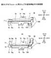
図2〜図5は、光モジュール4Aの一実施形態を説明する図である。図2は光モジュール4Aの斜視図であり、図3(A),(B)はフェルール用クリップ7Aの斜視図であり、図4はレンズ付きフェルール6の斜視図であり、図5は光モジュール4Aを下部筐体部2Bに装着した状態を示す斜視図である。 2-5 is a figure explaining one Embodiment of optical module 4A. 2 is a perspective view of the
MTフェルール5は、引き抜き方向側の端部に光ケーブル52が接続される。光ケーブル52は、複数の光ファイバーを有する多心の光ケーブルである。 In the MT ferrule 5, an
MTフェルール5の差し込み方向側の端部には、レンズ付きフェルール6と突き合わされる突き合わせ面が形成されている。突き合わせ面には、光ケーブル52に内設された光ファイバーの数に対応した複数の小孔が形成されている。 At the end of the MT ferrule 5 on the insertion direction side, a butting surface is formed to abut against the lens-equipped
小孔は、突き合わせ面に図中Y1,Y2方向に一列に並設されている。また各小孔は、MTフェルール5をX1,X2方向に貫通して形成されている。各小孔には、光ケーブル52の光ファイバーが挿入される。小孔に挿入された各光ファイバーの先端部は、突き合わせ面と同一面となるよう調整され、その後に接着剤により固定される。 The small holes are arranged in a line in the Y1 and Y2 directions in the drawing on the butted surfaces. Each small hole is formed through the MT ferrule 5 in the X1 and X2 directions. The optical fiber of the
突き合わせ面には、MTフェルールとレンズ付きフェルール6との位置決めを行うためのガイドピンが挿入されるガイドピン挿入孔が形成されている。ガイドピン挿入孔は、突き合わせ面の複数の小孔の両側に形成されている。 A guide pin insertion hole into which a guide pin for positioning the MT ferrule and the lens-equipped
レンズ付きフェルール6は、図4に示すように、フェルールベース61、フェルールカバー62、フェルールブーツ63を有している。 As shown in FIG. 4, the
レンズ付きフェルール6の差し込み方向側の端部には、フレキシブル光導波路67が接続される。フレキシブル光導波路67はポリイミド等の樹脂材料によりなるフィルム状の部材であり、光が通過する複数の光導波路コアが並列に形成されている。 A flexible
レンズ付きフェルール6は、引き抜き方向側の端部にMTフェルール5と突き合わされる突き合わせ面64を有している。突き合わせ面64は凹部68を有しており、凹部68の底面69には複数のレンズ部65が形成されている。 The lens-equipped
レンズ付きフェルール6はPBS(ポリブチレンサクシネート)等の透明樹脂により形成されており、レンズ部65はレンズ付きフェルール6の成形時に同時に形成される。レンズ部65は半球状の凸部である。 The lens-equipped
レンズ部65の形成位置は、MTフェルール5に形成された小孔(光ケーブル52の光ファイバーの先端部)の配設位置と対応するよう設定されている。また、レンズ部65の形成位置の両側部には、MTフェルール5とレンズ付きフェルール6との位置決めを行うためのガイドピンが挿入されるガイドピン挿入孔66が形成されている。 The formation position of the
フェルールベース61には、凹部61aが形成されている。凹部61aが形成されることによりフェルールベースは側面視で(Y2方向に見て)L字状の形状とされている。凹部61aには、フェルールブーツ63、フェルールカバー62、フレキシブル光導波路67が配設される。 The
フェルールブーツ63は、レンズ付きフェルール6の差し込み方向側の端部に配設される。フェルールブーツ63はフレキシブル光導波路67を保持するものであり、内部に形成された挿通孔にフレキシブル光導波路67が挿入される。 The
レンズ付きフェルール6を組み立てるには、予めフレキシブル光導波路67をフェルールブーツ63に挿通しておく。フレキシブル光導波路をフェルールブーツ63に挿通する際、フレキシブル光導波路67の先端が所定の長さだけフェルールブーツ63の先端からから延出するようにする(以下、フレキシブル光導波路67の延出した部分を延出部という)。また、フェルールベース61の凹部61aの突き合わせ面64に近い位置には、予め接着剤(例えば、紫外線硬化型接着剤)を塗布しておく。 In order to assemble the
次に、フェルールブーツ63と共にフレキシブル光導波路67を基部71の凹部61aに載置する。フレキシブル光導波路67を凹部61aに載置した状態で、延出部は凹部61aに塗布された接着剤の上部に位置している。しかしながら、紫外線硬化型接着剤はフレキシブル光導波路の載置時にはまだ硬化していないため、フレキシブル光導波路67はフェルールベース61に対して移動可能な状態となっている。 Next, the flexible
次に、凹部61aにフェルールカバー62を装着すると共に、フレキシブル光導波路67の位置決めを行う。フレキシブル光導波路67の突き合わせ方向の位置決めは、フレキシブル光導波路67の先端部を突き合わせ面64の背面(X1側の面)に突き当てることにより行う。 Next, the
また、フレキシブル光導波路67の高さ方向の位置決めは、フェルールカバー62でフレキシブル光導波路67を凹部61aの上面に押し付けることにより行う。 The flexible
また、フレキシブル光導波路67の幅方向の位置決めは、フェルールカバー62に形成された図に現れない位置決め突起を延出部の一側縁に接触させ、フェルールカバー62を凹部61a上でY1,Y2方向にスライドさせて延出部の他側縁を凹部61aに形成された位置決め突起に当接させることで行う。 Further, the positioning of the flexible
上記の位置決め処理を行うことにより、フレキシブル光導波路67はレンズ付きフェルール6に対して位置決めされる。位置決め処理が終了すると、紫外線硬化型接着剤に紫外線を照射する。レンズ付きフェルール6は透明樹脂により形成されているため、フェルールベース61及びフェルールカバー62の外部から紫外線硬化型接着剤に紫外線を照射することができる。 By performing the positioning process described above, the flexible
レンズ付きフェルール6は、フェルールベース61とフェルールカバー62を分離した構造であるため、フレキシブル光導波路67とフェルールベース61(レンズ部65)との位置決めを精度よく、かつ容易に行うことができる。 Since the
フレキシブル光導波路67の位置決めが終了すると、フェルールカバー62に形成された窓62bから接着剤62aが充填され、フェルールベース61、フェルールカバー62、及びフェルールブーツ63が接着される。 When the positioning of the flexible
光ケーブル52と光導波路67を接続するには、MTフェルール5の突き合わせ面と、レンズ付きフェルール6の突き合わせ面64とを突き合わせる。各突き合わせ面が突き合わされることにより、光ケーブル52の光ファイバーとフレキシブル光導波路67の光導波路コアは光学的に接続される。レンズ付きフェルール6はレンズ部65を有しているため、光ファイバーと光導波路コアとの光学的接続位置における光の拡散は防止され、光伝送効率の向上を図ることができる。 In order to connect the
また、光ファイバーと光導波路コアの良好な接続状態を維持するためには、MTフェルール5とレンズ付きフェルール6が所定の押圧力で突き合わされた状態を維持する必要がある。フェルール用クリップ7Aは、MTフェルール5とレンズ付きフェルール6に装着され、各フェルール5,6が所定の押圧力で突き合わされた状態を維持させる。なお、以下の説明においてMTフェルール5とレンズ付きフェルール6を総称してフェルール5,6ということがある。 In order to maintain a good connection state between the optical fiber and the optical waveguide core, it is necessary to maintain a state in which the MT ferrule 5 and the
次に、フェルール用クリップ7Aについて説明する。 Next, the
フェルール用クリップ7Aは、図3に示すように、基部71、ばね部72A、固定部74,75、係合部76、補強部78を有している。フェルール用クリップ7Aは、ばね材をプレス成形することにより一体形成されている。ばね材としては、ステンレス(SUS304,SUS631)、ベリリウム鋼(C1720)、りん青銅(C5210)等を用いることができるが、これに限定されるものではない。 As shown in FIG. 3, the ferrule clip 7 </ b> A has a
基部71は、フェルール5,6の突き合わせ方向を長手方向とした略長方形の形状を有している。基部71には、補強部78が形成されている。補強部78は、基部71の幅方向の略中央位置に、突き合わせ方向に延出するよう形成されている。 The
補強部78の図3の矢印B−B断面の形状は、本実施形態ではコ字形状としている。平板状の基部71に補強部78を設けることにより、基部71の実質的な断面積を増大することができ、よって基部71の剛性を高めることができる。 In the present embodiment, the shape of the cross section of the reinforcing
補強部78は、基部71の長手方向(フェルール5,6の突き合わせ方向)に形成されている。よって補強部78を設けるにより、基部71に曲げ方向(図3に矢印Cで示す方向)に撓みが発生することを防止することができる。本実施形態では、基部71に一つの補強部78を形成した例を示しているが、補強部78の形成数は一つに限定されるものではなく、基部71に必要とされる強度に対応して複数形成した構成としてもよい。 The reinforcing
ばね部72Aは、基部71の差し込み方向側の端部の両側に形成されている。ばね部72Aは、基部71に対し折り曲げ部79でZ2方向に略直角に折り曲げ、更に幅方向にU字状に曲げ形成することにより、突き合わせ方向にばね性を持たせた構成としている。なお、折り曲げ部79は、基部71の幅方向に延在している。 The
押圧部73Aは、各ばね部72Aの先端部に形成されている。本実施形態では、図3(B)に示されるように、押圧部73Aはばね部72Aの端部から引き抜き方向に突出するよう形成されている。また押圧部73Aは、ばね部72Aの先端部の基部71に近いZ1方向側の端部に形成されている。 73 A of press parts are formed in the front-end | tip part of each
固定部74,75は、基部71の長手方向の略中央位置から外側に向けて延出している。固定部74には光モジュール4Aを下部筐体部2Bに固定する際に用いるねじ26(図1参照)が挿通される挿通孔74aが形成されている。また固定部75には、光モジュール4Aを下部筐体部2Bに固定する際に下部筐体部2Bに形成されたボス28がかしめられるかしめ用孔75aが形成されている。 The fixing
係合部76は、基部71の引き抜き側の端部の両側に一体的に形成されている。係合部76は、基部71に対して係合部76を折り曲げ部77でZ2方向に折り曲げることにより形成される。 The engaging
折り曲げ部77の延在方向は、各フェルール5,6の突き合わせ方向と平行な方向とされている。よって係合部76のフェルール5,6の突き合わせ方向に対する剛性(機械的な強度)は、突き合わせ方向以外の方向に対する剛性に比べて高くなっている。 The extending direction of the
具体的には、図3(B)に矢印Eで示す方向に外力が印加された時に発生する係合部76の撓みは、矢印Eで示す方向以外の方向(例えば、図3(B)に矢印D方向)に外力が印加された時に発生する係合部76の撓みより小さくなる。 Specifically, the bending of the engaging
次に、光モジュール4Aの組み立て方法及び光コネクタ1の組み立て方法について説明する。 Next, an assembly method of the
光モジュール4Aを組み立てるには、まずMTフェルール5とレンズ付きフェルール6とを突き合わせる。この突き合わせを行う際、各フェルール5,6の突き合わせ面に形成されたガイドピン挿入孔にガイドピンを挿入する。このガイドピンにより、MTフェルール5とレンズ付きフェルール6の位置決めが行われ、光ケーブル52の光ファイバーとフレキシブル光導波路67の光導波路コアは、高い精度で光学的に接続される。 To assemble the
各フェルール5,6が突き合わされると、フェルール用クリップ7Aをフェルール5,6に装着する。フェルール用クリップ7Aをフェルール5,6に装着する際、フェルール用クリップ7Aの基部71には曲げ方向(図3に矢印Cで示す方向)に力が印加される。しかし、基部71は、補強部78が形成されることにより曲げ方向の剛性が高められている。 When the
よって、フェルール用クリップ7Aを各フェルール5,6に装着する際、基部71が撓むことはなく、光モジュール4Aの組み立てを容易に行うことができる。また装着後においては、基部71の変形に起因してフェルール5,6が離間することを防止することができる。 Therefore, when attaching the
ばね部72A及び係合部76の高さは、フェルール5,6の高さと等しいか、それより低く設定されている。よって、光モジュール4Aの高さHはフェルール5,6の高さと略等しい高さとなり、光モジュール4Aの低背化を図ることができる。 The height of the
図2に示すように、フェルール用クリップ7Aがフェルール5,6に装着された状態において、ばね部72Aはレンズ付きフェルール6に接触し、係合部76はMTフェルール5に係合する。 As shown in FIG. 2, in a state where the ferrule clip 7 </ b> A is attached to the
係合部76はMTフェルール5に係合する際、係合部76のX1方向側の縁部である側縁部76aは、MTフェルール5のY方向の幅が広くなった部分のX2側の面に接し、よってMTフェルール5とレンズ付きフェルール6は係合部76とばね部72Aとの間で挟持される。 When the engaging
またばね部72Aの押圧部73Aは、フェルールベース61のX1方向側の後端部(背面)を押圧するよう設定されている。よって、ばね部72Aの復元力は、フェルールベース61にのみ印可される。 The
押圧部73Aがフェルールカバー62を押圧する構成とした場合には、フェルールカバー62はフェルールベース61に接着した構成であるため、ばね部72Aの復元力はフェルールベース61に接着されたフェルールカバー62を剥がすように作用する。よって、押圧部73Aがフェルールカバー62を押圧する構成では、フェルールベース61からフェルールカバー62が離脱するおそれがある。 When the
これに対し本実施形態のように、押圧部73Aがフェルールベース61と接触(当接)する構成とすることにより、フェルールカバー62がフェルールベース61から離脱することを防止することができる。 On the other hand, the configuration in which the pressing portion 73 </ b> A is in contact (contact) with the
フェルール用クリップ7Aがフェルール5,6に装着されることにより、係合部76はMTフェルール5のX2方向側の後端部(背面)に係合する。係合部76がMTフェルール5に係合する際、係合76の側縁部76aがMTフェルール5の背面に当接する。 When the
このように、ばね部72Aがレンズ付きフェルール6と係合すると共に係合部76がMTフェルール5と係合することにより、フェルール用クリップ7Aはフェルール5,6に装着され、光モジュール4Aの組み立ては完了する。 Thus, when the
光モジュール4Aが組み立てられると、フレキシブル光導波路67にプリント基板8の光電変換部81が接続される。また光モジュール4Aの引き抜き方向側には、ケーブルブーツ90(スリーブ92,かしめリング93を含む)及びプルタブ95が配設される。 When the optical module 4 </ b> A is assembled, the
プリント基板8、ケーブルブーツ90、プルタブ95等が配設された光モジュール4Aは、筐体2に装着される。筐体2の上部筐体部2A及び下部筐体部2Bには、光モジュール4Aが装着されるモジュール装着部21と、プリント基板8が装着される基板装着部22が形成されている。 The optical module 4 </ b> A on which the printed circuit board 8, the
光モジュール4Aを筐体2に装着するには、光モジュール4Aをケーブルブーツ90と共に下部筐体部2Bのモジュール装着部21に挿入する。光モジュール4Aを下部筐体部2Bに挿入した状態で、フェルール用クリップ7Aの挿通孔74aとねじ孔27は対向し、下部筐体部2Bに突設されたボス28はかしめ用孔75aに挿入される。 In order to mount the
次に、挿通孔74aにねじ26を挿通してねじ孔27に螺着すると共にボス28をかしめる。これによって光モジュール4Aは、下部筐体部2B(筐体2)に固定される。またプリント基板8は、接着剤を用いて基板装着部22に固定される。 Next, the
光モジュール4A及びプリント基板8が下部筐体部2Bに装着されると、下部筐体部2Bに上部筐体部2Aを被せ、ねじ24を挿通孔23に挿入してねじ孔25に螺着することにより、光コネクタ1の組み立ては完了する。 When the
この光コネクタ1の組み立ての際、光ケーブル52が引き抜き方向に引っ張られるおそれがある。また光ケーブル52は、光コネクタ1を電子機器に対して引き抜き操作する際にも引っ張られるおそれがある。光ケーブル52が引っ張られた場合、この引っ張り力によりMTフェルール5は引き抜き方向に移動付勢される。 When the
しかし、MTフェルール5の背面には係合部76が係合している。この係合部76の突き合わせ方向に対する剛性は、他の方向に対する剛性に比べて高くなっている。また引っ張り力によりMTフェルール5が移動付勢される方向は、係合部76の剛性が高い方向と一致している。よって、光ケーブル52が引っ張られても、係合部76によりレンズ付きフェルール6が引き抜き方向へ移動することを防止できる。 However, the engaging
このように本実施形態に係る光モジュール4A及びこれを用いた光コネクタ1では、光ケーブル52が引っ張られても、MTフェルール5とレンズ付きフェルール6は良好な光学的接続状態を維持することができる。よって、光モジュール4A及びこれを用いた光コネクタ1の信頼性を高めることができる。 As described above, in the
また本実施形態に係る光コネクタ1では、光モジュール4Aを筐体2に固定する際、基部71の両側に形成された固定部74,75は下部筐体部2Bに固定される。固定部74,75を筐体2に固定する際、固定部74,75には応力が発生する。 Further, in the
しかし、固定部74,75の形成位置はばね部72Aの形成位置から離間しており、ねじ26の締め付けやボス28のかしめにより発生する応力がばね部72Aに影響を及ぼすようなことはない。よって、ばね部72Aは安定してレンズ付きフェルール6をMTフェルール5に向け押圧するため、信頼性の高い光学的な接続を行うことができる。 However, the positions where the fixing
図6は、フェルール用クリップ7Aの変形例であるフェルール用クリップ7Bを示している。なお、図6において、図1〜図5に示した構成と対応する構成については同一符号を付し、適宜その説明を省略する。 FIG. 6 shows a ferrule clip 7B which is a modification of the
図3に示したフェルール用クリップ7Aでは、ばね部72Aの先端部に形成される押圧部73Aが、ばね部72Aの端部から引き抜き方向に突出する形状とされていた。これに対して本変形例の押圧部73Bは、ばね部72Bの先端からU字状(湾曲状)に曲げられた形状とされている。本変形例のように押圧部73Bの形状をU字形状とすることにより、押圧部73Bにもばね性を持たせることが可能となる。 In the
次に、図7〜図9を用いて他の実施形態による光モジュール4Bについて説明する。 Next, an
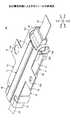
図7は光モジュール4Bの斜視図である。図8(A),(B)は光モジュール4Bに設けられるフェルール用クリップ7Cの斜視図であり、図9は光モジュール4Bを下部筐体部2Bに装着した状態を示している。なお、図7〜図9において、図1〜図5に示した構成と対応する構成については同一符号を付し、適宜その説明を省略する。 FIG. 7 is a perspective view of the
光モジュール4Bは、フェルール用クリップ7Cのばね部72Cを略C字形状に形成している。またばね部72Cは、フェルール用クリップ7Cの差し込み方向端部から上下方向(Z1,Z2方向)に延在するよう形成されている。更にばね部72C及び係合部76の高さは、各フェルール5,6の高さと等しいか、それより低く設定されている。 In the
よって、光モジュール4Bの高さは各フェルール5,6の高さと略等しい高さとなり、光モジュール4Aの低背化を図ることができる。 Therefore, the height of the
ばね部72Cの先端部に形成される押圧部73Cは、ばね部72Cの端部から引き抜き方向に突出する形状とされている。本実施形態でも、押圧部73Cはレンズ付きフェルール6のフェルールベース61にのみ接触し、フェルールカバー62には接触しないよう構成されている。 The
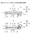
図10〜図13は、図8に示したフェルール用クリップ7Cの変形例であるフェルール用クリップ7D〜7Gを示している。なお、図10〜図13において、図1〜図5に示した構成と対応する構成については同一符号を付し、適宜その説明を省略する。また図10(A),(B)〜図13(A),(B)はフェルール用クリップ7D〜7Gの斜視図である。 10 to 13 show ferrule clips 7D to 7G, which are modified examples of the ferrule clip 7C shown in FIG. 10 to 13, components corresponding to those shown in FIGS. 1 to 5 are denoted by the same reference numerals, and description thereof is omitted as appropriate. FIGS. 10A, 10B, 13A, and 13B are perspective views of
図10(A,),(B)に示すフェルール用クリップ7Dは、ばね部72Dの形状を略S字形状に成形したものである。またフェルール用クリップ7Dには、補強部が形成されていない。補強部を設けなくても基部71が所定の剛性を有する場合には、必ずしも補強部は設ける必要はない。同様に、フェルール用クリップ7E〜7Gにおいても、ばね部72E〜72Gに補強部を必ずしも設ける必要はない。 A
図11(A),(B)に示すフェルール用クリップ7Eは、ばね部72Eの先端に断面半円形状の小突起である押圧部73Eを設けたものである。図11(C)は、押圧部73Eを拡大して示す斜視図である。またばね部72Eは、基部71の差し込み側の端部71aよりも差し込み方向に深く延出した構成とされている。 A
図12(A),(B)に示すフェルール用クリップ7Fは、ばね部72Fの形状を略S字形状とすると共に、ばね部72Fの先端に断面半円形状の小突起である押圧部73Fを設けたものである。またばね部72Fは、基部71の内側(図中X2方向側)に深く延出した構成とされている。 In the
図13(A),(B)に示すフェルール用クリップ7Gは、ばね部72Gの形状を略S字形状とすると共に、ばね部72Gの先端に断面半円形状の小突起である押圧部73Gを設けたものである。また押圧部73Gの位置を、図12(A),(B)に示したフェルール用クリップ7Fの押圧部73Fの位置よりも基部71の差し込み側の端部に近い位置とした構成とされている。 In the
以上、本発明の好ましい実施形態について詳述したが、本発明は上記した特定の実施形態に限定されるものではなく、特許請求の範囲に記載された本発明の要旨の範囲内において、種々の変形・変更が可能なものである。 The preferred embodiments of the present invention have been described in detail above. However, the present invention is not limited to the specific embodiments described above, and various modifications are possible within the scope of the gist of the present invention described in the claims. It can be modified and changed.
例えば、上記の各実施形態及び変形例では、その全体をばね性を有する金属から形成したフェルール用クリップ7A〜7Gを用いた例を示した。しかしながら,フェルール用クリップは必ずしもその全体を金属により構成する必要はなく、金属と樹脂との複合構造としても、また樹脂のみより形成することも可能である。 For example, in each of the above-described embodiments and modifications, examples using ferrule clips 7 </ b> A to 7 </ b> G formed entirely from a metal having a spring property are shown. However, the entire ferrule clip is not necessarily made of metal, and may be formed of a composite structure of metal and resin, or may be formed of resin alone.
1 光コネクタ
2 筐体
2A 上部筐体部
2B 下部筐体部
21 モジュール装着部
28 ボス
4A,4B 光モジュール
5 MTフェルール
52 光ケーブル
6 レンズ付きフェルール
61 フェルールベース
62 フェルールカバー
63 フェルールブーツ
64 突き合わせ面
65 レンズ部
66 ガイドピン挿入孔
67 フレキシブル光導波路
7A〜7G フェルール用クリップ
71 基部
72A〜72G ばね部
73A〜73G 押圧部
74,75 固定部
76 係合部
76a 側縁部
77 折り曲げ部
78 補強部
8 プリント基板
90 ケーブルブーツ
92 スリーブ
93 かしめリング
94 アーム部
95 プルタブDESCRIPTION OF
Claims (7)
Translated fromJapanese基部と、
前記基部に形成され、前記第1のフェルールと前記第2のフェルールが突き合わされる突き合わせ方向に弾性力を付勢するばね部と、
前記基部に形成され、前記突き合わせ方向に対する剛性が他の方向に対して高い係合部とを有し、
前記係合部は、前記第2のフェルールと前記突き合わせ方向に係合するものであって、
前記基部には、前記突き合わせ方向に垂直な断面の形状がコ字形状であって、前記突き合わせ方向と平行に延在する補強部が設けられており、
前記補強部は、前記基部の幅方向の略中央位置に形成されていることを特徴とするフェルール用クリップ。A ferrule clip for matching a first ferrule and a second ferrule,
The base,
A spring portion that is formed on the base and urges an elastic force in a butting direction in which the first ferrule and the second ferrule are butted;
An engagement portion formed on the base portion and having a high rigidity with respect to the butting direction with respect to the other direction;
The engaging portion engages with the second ferrule in the abutting direction,
The base portion has a U-shaped cross section perpendicular to the abutting direction, and a reinforcing portion extending in parallel with the abutting direction is provided.
The ferrule clip, wherein the reinforcing portion is formed at a substantially central position in the width direction of the base portion .
前記第2のフェルールは前記係合部の側縁部と係合することを特徴とする請求項1記載のフェルール用クリップ。The engaging portion is formed at a substantially right angle with a bent portion extending in parallel with the abutting direction,
The ferrule clip according to claim 1, wherein the second ferrule is engaged with a side edge portion of the engaging portion.
前記係合部は、前記フェルールベースと係合する構成としたことを特徴とする請求項1乃至3のいずれか一項に記載のフェルール用クリップ。The second ferrule has a ferrule base and a ferrule cover disposed on the ferrule base,
The ferrule clip according to any one of claims 1 to 3, wherein the engagement portion is configured to engage with the ferrule base.
第2のフェルールと、
請求項1乃至5のいずれか一項に記載のフェルール用クリップと
を有することを特徴とする光モジュール。A first ferrule;
A second ferrule;
An optical module comprising the ferrule clip according to any one of claims 1 to5 .
第1のフェルールと、第2のフェルールと、請求項1乃至5のいずれか一項に記載のフェルール用クリップとを有する光モジュールと
を有することを特徴とする光コネクタ。A housing,
An optical connector comprising: an optical module having a first ferrule, a second ferrule, and the ferrule clip according to any one of claims 1 to5 .
Priority Applications (2)
| Application Number | Priority Date | Filing Date | Title |
|---|---|---|---|
| JP2014201657AJP6498903B2 (en) | 2014-09-30 | 2014-09-30 | Clip for ferrule, optical module and optical connector |
| US14/856,722US9453975B2 (en) | 2014-09-30 | 2015-09-17 | Clip, optical module, and optical connector |
Applications Claiming Priority (1)
| Application Number | Priority Date | Filing Date | Title |
|---|---|---|---|
| JP2014201657AJP6498903B2 (en) | 2014-09-30 | 2014-09-30 | Clip for ferrule, optical module and optical connector |
Publications (2)
| Publication Number | Publication Date |
|---|---|
| JP2016071205A JP2016071205A (en) | 2016-05-09 |
| JP6498903B2true JP6498903B2 (en) | 2019-04-10 |
Family
ID=55584174
Family Applications (1)
| Application Number | Title | Priority Date | Filing Date |
|---|---|---|---|
| JP2014201657AExpired - Fee RelatedJP6498903B2 (en) | 2014-09-30 | 2014-09-30 | Clip for ferrule, optical module and optical connector |
Country Status (2)
| Country | Link |
|---|---|
| US (1) | US9453975B2 (en) |
| JP (1) | JP6498903B2 (en) |
Families Citing this family (9)
| Publication number | Priority date | Publication date | Assignee | Title |
|---|---|---|---|---|
| JP6498903B2 (en)* | 2014-09-30 | 2019-04-10 | 富士通コンポーネント株式会社 | Clip for ferrule, optical module and optical connector |
| US9720188B2 (en) | 2015-12-31 | 2017-08-01 | International Business Machines Corporation | Connecting mid-board optical modules |
| JP2018017861A (en)* | 2016-07-27 | 2018-02-01 | 富士通コンポーネント株式会社 | Optical module |
| WO2018163498A1 (en)* | 2017-03-08 | 2018-09-13 | ソニー・オリンパスメディカルソリューションズ株式会社 | Medical device and method for manufacturing medical device |
| US11221449B2 (en) | 2018-05-11 | 2022-01-11 | Sumitomo Electric Industries, Ltd. | Optical connector, optical module and clip member |
| CN110703390B (en)* | 2018-07-09 | 2021-07-20 | 菲尼萨公司 | Latch mechanism, connection method and optoelectronic system between ferrule and lens |
| CN112771425A (en)* | 2018-09-20 | 2021-05-07 | 扇港元器件股份有限公司 | Stackable adapter housing for opposed MT ferrules |
| US12248190B2 (en)* | 2021-12-12 | 2025-03-11 | Molex, Llc | Biased connector system |
| JP2023176616A (en)* | 2022-05-31 | 2023-12-13 | 住友電気工業株式会社 | Optical connector module, optical coupling structure, connecting member, and connecting method |
Family Cites Families (20)
| Publication number | Priority date | Publication date | Assignee | Title |
|---|---|---|---|---|
| US6095695A (en)* | 1996-10-28 | 2000-08-01 | Sumitomo Electric Industries, Ltd. | Optical connector, and using method and tool thereof |
| JP2987356B2 (en)* | 1998-02-24 | 1999-12-06 | 沖電気工業株式会社 | Optical connector |
| JP4128830B2 (en)* | 2002-08-30 | 2008-07-30 | 古河電気工業株式会社 | Optical fiber array type ferrule and optical fiber array type connector |
| JP2004191564A (en)* | 2002-12-10 | 2004-07-08 | Mitsubishi Electric Corp | Optical path conversion connector |
| JP4153418B2 (en)* | 2003-12-16 | 2008-09-24 | 株式会社巴川製紙所 | Optical connection structure |
| US7404680B2 (en)* | 2004-05-31 | 2008-07-29 | Ngk Spark Plug Co., Ltd. | Optical module, optical module substrate and optical coupling structure |
| WO2007053660A1 (en)* | 2005-11-01 | 2007-05-10 | Molex Incorporated | Locking mechanism for optical tranceivers |
| US7578623B2 (en)* | 2006-08-21 | 2009-08-25 | Intel Corporation | Aligning lens carriers and ferrules with alignment frames |
| US8104973B2 (en)* | 2007-02-09 | 2012-01-31 | Us Conec, Ltd. | Ferrule-to-ferrule adapter and ferrule adapter assembly |
| JP2008225339A (en)* | 2007-03-15 | 2008-09-25 | Hitachi Cable Ltd | Optical system connection structure, optical member, and optical transmission module |
| US20090245736A1 (en)* | 2008-03-31 | 2009-10-01 | Ahadian Joseph F | Connector attachment to a low height profile module |
| JP2010096838A (en)* | 2008-10-14 | 2010-04-30 | Advanced Cable Systems Corp | Optical connector |
| US8485735B2 (en)* | 2008-12-19 | 2013-07-16 | US Conec, Ltd | Field install fiber clip and method of use |
| JP2011075814A (en) | 2009-09-30 | 2011-04-14 | Fujikura Ltd | Clip for optical connector, connector assembly with reinforcing clip, and method for assembling the same |
| CN102346279B (en)* | 2010-07-30 | 2015-03-11 | 株式会社藤仓 | Optical connector and connector connection system |
| JP5667525B2 (en)* | 2011-06-15 | 2015-02-12 | 日本航空電子工業株式会社 | Optical connector |
| US20130216190A1 (en)* | 2012-02-20 | 2013-08-22 | Tyco Electronics Corporation | Optical assembly with ferrule and frame |
| JP5983456B2 (en)* | 2013-02-15 | 2016-08-31 | 日立金属株式会社 | Ferrule fixing member |
| JP2015125217A (en)* | 2013-12-26 | 2015-07-06 | 住友電気工業株式会社 | Optical coupling mechanism and optical transceiver |
| JP6498903B2 (en)* | 2014-09-30 | 2019-04-10 | 富士通コンポーネント株式会社 | Clip for ferrule, optical module and optical connector |
- 2014
- 2014-09-30JPJP2014201657Apatent/JP6498903B2/ennot_activeExpired - Fee Related
- 2015
- 2015-09-17USUS14/856,722patent/US9453975B2/ennot_activeExpired - Fee Related
Also Published As
| Publication number | Publication date |
|---|---|
| US20160091670A1 (en) | 2016-03-31 |
| JP2016071205A (en) | 2016-05-09 |
| US9453975B2 (en) | 2016-09-27 |
Similar Documents
| Publication | Publication Date | Title |
|---|---|---|
| JP6498903B2 (en) | Clip for ferrule, optical module and optical connector | |
| JP2016224346A (en) | Optical connector | |
| JP6044446B2 (en) | Ferrule fixing member and ferrule holding structure | |
| JP4818666B2 (en) | Optical connector receptacle, PCB with optical connector receptacle | |
| JP4942327B2 (en) | Optical connector | |
| JP4116017B2 (en) | Optical connector | |
| JP4800136B2 (en) | Optical receptacle housing, optical connector receptacle and optical device | |
| US9964714B2 (en) | Optical connector | |
| US9690059B2 (en) | Optical module | |
| US8905649B2 (en) | Optical fiber terminal fixing member, optical connector, and optical fiber cable with connector | |
| JP2012093536A (en) | Optical module | |
| EP2631691A1 (en) | Optical fiber terminal, optical fiber cable with terminal, optical connector, optical fiber cable with connector, and connection structure | |
| US20140321818A1 (en) | Electronic device with cable | |
| JP2011123429A (en) | Connection structure of optical connector and lens block, and optical module equipped with the same | |
| JP5622476B2 (en) | Optical connector, connector connection system | |
| JP6564566B2 (en) | Optical connector structure | |
| JP6215022B2 (en) | Photoelectric composite connector | |
| WO2013089737A2 (en) | Optical connector | |
| JP5269746B2 (en) | Optical connector | |
| JP4821619B2 (en) | Optical module | |
| JP2016090858A (en) | Optical assembly | |
| JP6460747B2 (en) | Optical connector structure | |
| JP2015031867A (en) | Optical module | |
| WO2023058634A1 (en) | Photoelectric composite connector | |
| US20240402436A1 (en) | Photoelectric composite connector |
Legal Events
| Date | Code | Title | Description |
|---|---|---|---|
| A621 | Written request for application examination | Free format text:JAPANESE INTERMEDIATE CODE: A621 Effective date:20170801 | |
| A977 | Report on retrieval | Free format text:JAPANESE INTERMEDIATE CODE: A971007 Effective date:20180712 | |
| A131 | Notification of reasons for refusal | Free format text:JAPANESE INTERMEDIATE CODE: A131 Effective date:20180717 | |
| A521 | Request for written amendment filed | Free format text:JAPANESE INTERMEDIATE CODE: A523 Effective date:20180914 | |
| A131 | Notification of reasons for refusal | Free format text:JAPANESE INTERMEDIATE CODE: A131 Effective date:20181211 | |
| A521 | Request for written amendment filed | Free format text:JAPANESE INTERMEDIATE CODE: A523 Effective date:20190206 | |
| TRDD | Decision of grant or rejection written | ||
| A01 | Written decision to grant a patent or to grant a registration (utility model) | Free format text:JAPANESE INTERMEDIATE CODE: A01 Effective date:20190305 | |
| A61 | First payment of annual fees (during grant procedure) | Free format text:JAPANESE INTERMEDIATE CODE: A61 Effective date:20190314 | |
| R150 | Certificate of patent or registration of utility model | Ref document number:6498903 Country of ref document:JP Free format text:JAPANESE INTERMEDIATE CODE: R150 | |
| LAPS | Cancellation because of no payment of annual fees |