JP6497931B2 - Surgical equipment - Google Patents
Surgical equipmentDownload PDFInfo
- Publication number
- JP6497931B2 JP6497931B2JP2014260009AJP2014260009AJP6497931B2JP 6497931 B2JP6497931 B2JP 6497931B2JP 2014260009 AJP2014260009 AJP 2014260009AJP 2014260009 AJP2014260009 AJP 2014260009AJP 6497931 B2JP6497931 B2JP 6497931B2
- Authority
- JP
- Japan
- Prior art keywords
- assembly
- jaw member
- firing
- cam bar
- cam
- Prior art date
- Legal status (The legal status is an assumption and is not a legal conclusion. Google has not performed a legal analysis and makes no representation as to the accuracy of the status listed.)
- Active
Links
- 238000010304firingMethods0.000claimsdescription149
- 238000004587chromatography analysisMethods0.000claims1
- 238000010168coupling processMethods0.000description15
- 230000008878couplingEffects0.000description12
- 238000005859coupling reactionMethods0.000description12
- 238000005520cutting processMethods0.000description4
- 210000005166vasculatureAnatomy0.000description4
- 238000002513implantationMethods0.000description3
- 238000000034methodMethods0.000description3
- 230000000712assemblyEffects0.000description2
- 238000000429assemblyMethods0.000description2
- 230000017531blood circulationEffects0.000description2
- 239000012636effectorSubstances0.000description2
- 239000002184metalSubstances0.000description2
- 238000003466weldingMethods0.000description2
- 239000000853adhesiveSubstances0.000description1
- 230000001070adhesive effectEffects0.000description1
- 230000000295complement effectEffects0.000description1
- 238000004519manufacturing processMethods0.000description1
- 239000000463materialSubstances0.000description1
- 238000012986modificationMethods0.000description1
- 230000004048modificationEffects0.000description1
- 238000001356surgical procedureMethods0.000description1
Images


Classifications
- A—HUMAN NECESSITIES
- A61—MEDICAL OR VETERINARY SCIENCE; HYGIENE
- A61B—DIAGNOSIS; SURGERY; IDENTIFICATION
- A61B17/00—Surgical instruments, devices or methods
- A61B17/068—Surgical staplers, e.g. containing multiple staples or clamps
- A61B17/072—Surgical staplers, e.g. containing multiple staples or clamps for applying a row of staples in a single action, e.g. the staples being applied simultaneously
- A61B17/07207—Surgical staplers, e.g. containing multiple staples or clamps for applying a row of staples in a single action, e.g. the staples being applied simultaneously the staples being applied sequentially
- A—HUMAN NECESSITIES
- A61—MEDICAL OR VETERINARY SCIENCE; HYGIENE
- A61B—DIAGNOSIS; SURGERY; IDENTIFICATION
- A61B17/00—Surgical instruments, devices or methods
- A61B17/068—Surgical staplers, e.g. containing multiple staples or clamps
- A61B17/072—Surgical staplers, e.g. containing multiple staples or clamps for applying a row of staples in a single action, e.g. the staples being applied simultaneously
- A—HUMAN NECESSITIES
- A61—MEDICAL OR VETERINARY SCIENCE; HYGIENE
- A61B—DIAGNOSIS; SURGERY; IDENTIFICATION
- A61B17/00—Surgical instruments, devices or methods
- A61B17/068—Surgical staplers, e.g. containing multiple staples or clamps
- A61B17/0682—Surgical staplers, e.g. containing multiple staples or clamps for applying U-shaped staples or clamps, e.g. without a forming anvil
- A—HUMAN NECESSITIES
- A61—MEDICAL OR VETERINARY SCIENCE; HYGIENE
- A61B—DIAGNOSIS; SURGERY; IDENTIFICATION
- A61B17/00—Surgical instruments, devices or methods
- A61B2017/0046—Surgical instruments, devices or methods with a releasable handle; with handle and operating part separable
- A—HUMAN NECESSITIES
- A61—MEDICAL OR VETERINARY SCIENCE; HYGIENE
- A61B—DIAGNOSIS; SURGERY; IDENTIFICATION
- A61B17/00—Surgical instruments, devices or methods
- A61B17/068—Surgical staplers, e.g. containing multiple staples or clamps
- A61B17/072—Surgical staplers, e.g. containing multiple staples or clamps for applying a row of staples in a single action, e.g. the staples being applied simultaneously
- A61B2017/07214—Stapler heads
- A61B2017/07257—Stapler heads characterised by its anvil
- A—HUMAN NECESSITIES
- A61—MEDICAL OR VETERINARY SCIENCE; HYGIENE
- A61B—DIAGNOSIS; SURGERY; IDENTIFICATION
- A61B17/00—Surgical instruments, devices or methods
- A61B17/068—Surgical staplers, e.g. containing multiple staples or clamps
- A61B17/072—Surgical staplers, e.g. containing multiple staples or clamps for applying a row of staples in a single action, e.g. the staples being applied simultaneously
- A61B2017/07214—Stapler heads
- A61B2017/07271—Stapler heads characterised by its cartridge
- A—HUMAN NECESSITIES
- A61—MEDICAL OR VETERINARY SCIENCE; HYGIENE
- A61B—DIAGNOSIS; SURGERY; IDENTIFICATION
- A61B17/00—Surgical instruments, devices or methods
- A61B17/068—Surgical staplers, e.g. containing multiple staples or clamps
- A61B17/072—Surgical staplers, e.g. containing multiple staples or clamps for applying a row of staples in a single action, e.g. the staples being applied simultaneously
- A61B2017/07214—Stapler heads
- A61B2017/07278—Stapler heads characterised by its sled or its staple holder
Landscapes
- Health & Medical Sciences (AREA)
- Life Sciences & Earth Sciences (AREA)
- Surgery (AREA)
- Heart & Thoracic Surgery (AREA)
- Engineering & Computer Science (AREA)
- Biomedical Technology (AREA)
- Nuclear Medicine, Radiotherapy & Molecular Imaging (AREA)
- Medical Informatics (AREA)
- Molecular Biology (AREA)
- Animal Behavior & Ethology (AREA)
- General Health & Medical Sciences (AREA)
- Public Health (AREA)
- Veterinary Medicine (AREA)
- Surgical Instruments (AREA)
Description
Translated fromJapanese 背景
技術分野
本開示は、外科手術装置に関する。より詳細には、本開示は、発射アセンブリを含む外科手術ステープラーに関し、この発射アセンブリは、顎部材が締め付け構成にあり、外科手術ステープラーが発射される場合、ステープラーの顎部材間の組織ギャップの距離を制御するように構成されている。BACKGROUND Technical Field The present disclosure relates to a surgical apparatus. More particularly, the present disclosure relates to a surgical stapler that includes a firing assembly that includes a tissue gap distance between the staple members of the stapler when the jaw members are in a clamped configuration and the surgical stapler is fired. Is configured to control.
関連技術の説明
組織を締め付け、ステープル留めするように構成されている外科手術ステープラーは公知である。そのようなステープラーは、ツールアセンブリを含み得、このツールアセンブリは、ステープラーのシャフトの遠位端において支持されている。ツールアセンブリは、例えば、アンビルとカートリッジとを含み得、このカートリッジは、複数のファスナーを含み、複数のファスナーは、組織をステープル留めする(例えば、移植手順中に脈管構造を塞ぐ)ように構成されている。Description of Related Art Surgical staplers that are configured to clamp and staple tissue are known. Such a stapler may include a tool assembly that is supported at the distal end of the shaft of the stapler. The tool assembly can include, for example, an anvil and a cartridge, the cartridge including a plurality of fasteners configured to staple tissue (eg, occlude vasculature during an implantation procedure). Has been.
そのようなステープラーを用いて組織をステープル留めするために、組織がカートリッジとアンビルとの間に位置決めされ得、アンビルが、カートリッジに向かって接近させられて、組織を締め付け得る。組織が締め付けられると、ステープラーは、発射され、カートリッジを通してステープラーの駆動アセンブリを遠位方向に前進させて、カートリッジから複数の外科手術ファスナーを連続して射出して、組織をステープル留めし得る。 In order to staple tissue using such a stapler, the tissue can be positioned between the cartridge and the anvil, and the anvil can be moved toward the cartridge to clamp the tissue. As the tissue is clamped, the stapler may be fired and the stapler drive assembly advanced distally through the cartridge to sequentially fire a plurality of surgical fasteners from the cartridge to staple the tissue.
複数のファスナーを発射するための記載された機構の他に、従来のステープラーは、ステープラーの発射中に、ツールアセンブリのアンビルとカートリッジとの間の組織ギャップの距離を制御するように構成されている構造をさらに含み得る。 In addition to the described mechanism for firing a plurality of fasteners, conventional staplers are configured to control the distance of the tissue gap between the anvil of the tool assembly and the cartridge during firing of the stapler. It may further include a structure.
前述のステープラーは、上記用途のためには満足のいくものであり得るが、外科手術ファスナーを発射し、かつ/またはカートリッジをアンビルに向かって接近させるためのより単純な設計の必要性が存在し得る。代替の接近アセンブリおよび/または方法の必要性だけではなく、より少ない空間を占める発射アセンブリの必要性も存在する。 While the aforementioned stapler may be satisfactory for the above applications, there is a need for a simpler design for firing surgical fasteners and / or moving the cartridge toward the anvil. obtain. There is a need not only for alternative access assemblies and / or methods, but also for launch assemblies that occupy less space.
概要
本開示の局面は、外科手術ステープル留め装置を提供する。外科手術ステープル留め装置は、作動デバイスを含み、この作動デバイスは、細長いシャフトを含む。ツールアセンブリは、シャフトの遠位端に配置されている。ツールアセンブリは、外科手術ステープル留め装置のシャフトの遠位端に取り外し可能に結合可能であり得る。ツールアセンブリは、カートリッジアセンブリを支持している第1の顎部材であって、このカートリッジアセンブリは、複数の外科手術ファスナーを有する、第1の顎部材と、アンビルを支持している第2の顎部材とを含む。第1の顎部材は、間隔が空けられた位置と接近させられた位置との間を第2の顎部材に対して移動可能である。第1および第2の顎部材のうちの1つは、その近位端においてカンチレバーを含む。カンチレバーは、ブリッジの形態であり得、このブリッジは、外科手術ステープル留め装置のシャフトを通して規定される長手方向軸に対して横方向に延びている。発射カムバーアセンブリは、ツールアセンブリ内にスライド可能に配置されている。発射カムバーアセンブリは、カンチレバーを係合して第1および第2の顎部材を接近させられた位置に向かって移動させるように構成されているカム表面と、発射カムバーアセンブリがツールアセンブリを通って遠位方向に並進させられる場合、カートリッジから複数の外科手術ファスナーを配備するように構成されている遠位端とを含む。SUMMARY An aspect of the present disclosure provides a surgical stapling apparatus. The surgical stapling apparatus includes an actuation device that includes an elongate shaft. The tool assembly is disposed at the distal end of the shaft. The tool assembly may be removably connectable to the distal end of the shaft of the surgical stapling apparatus. The tool assembly is a first jaw member supporting a cartridge assembly, the cartridge assembly having a first jaw member having a plurality of surgical fasteners and a second jaw supporting an anvil. Member. The first jaw member is movable relative to the second jaw member between a spaced position and an approximated position. One of the first and second jaw members includes a cantilever at its proximal end. The cantilever may be in the form of a bridge that extends transverse to the longitudinal axis defined through the shaft of the surgical stapling apparatus. The firing cam bar assembly is slidably disposed within the tool assembly. The firing cam bar assembly includes a cam surface configured to engage the cantilever to move the first and second jaw members toward the approximated position, and the firing cam bar assembly passes through the tool assembly. A distal end configured to deploy a plurality of surgical fasteners from the cartridge.
発射カムバーアセンブリは、第1の発射カムバーを含み得、この第1の発射カムバーは、細長い構成を有し、カム表面を規定する遠位部分を有する。外科手術ステープラーは、第2の発射カムバーをさらに含み得、この第2の発射カムバーは、細長い構成を有し、カム表面を規定する遠位部分を有し、第2の発射カムバーは、第1の発射カムバー内に置かれている。カートリッジは、複数のプッシャーを含み得、第1および第2の発射カムバーの遠位部分は、カートリッジの複数のプッシャーに接触して複数の外科手術ファスナーをカートリッジから配備するように構成されている。 The firing cam bar assembly may include a first firing cam bar, the first firing cam bar having an elongated configuration and having a distal portion defining a cam surface. The surgical stapler may further include a second firing cam bar, the second firing cam bar having an elongated configuration and having a distal portion defining a cam surface, the second firing cam bar being a first firing cam bar. Is placed in the firing cam bar. The cartridge may include a plurality of pushers, and the distal portions of the first and second firing cam bars are configured to contact the plurality of pushers of the cartridge to deploy a plurality of surgical fasteners from the cartridge.
発射カムバーアセンブリのカム表面は、第1のカム部分を含み得、この第1のカム部分は、第2のカム部分に対して遠位方向に、かつある角度で配置されている。カム表面の第2のカム部分は、発射カムバーアセンブリの近位端に向かって内方にテーパをつけられ得る。 The cam surface of the firing cam bar assembly may include a first cam portion that is disposed distally and at an angle with respect to the second cam portion. The second cam portion of the cam surface may be tapered inwardly toward the proximal end of the firing cam bar assembly.
カートリッジをアンビルから離れるほうに半径方向に付勢するための弾性部材が、カートリッジ上に提供され得る。弾性部材は、カートリッジの近位端に結合されている近位端と、アンビルの少なくとも一部分に接触するように位置決めされている遠位端とを含み得る。弾性部材の近位端は、2つのフィンガー部分を含み得、2つのフィンガー部分は、カートリッジの近位端に規定される2つの対応するアパーチャー内に置かれている。 A resilient member may be provided on the cartridge for urging the cartridge radially away from the anvil. The resilient member can include a proximal end coupled to the proximal end of the cartridge and a distal end positioned to contact at least a portion of the anvil. The proximal end of the elastic member may include two finger portions that are placed in two corresponding apertures defined at the proximal end of the cartridge.
本開示の局面は、外科手術ステープル留め装置との使用のために構成されているリロードを提供する。リロードは、シャフトを含み、このシャフトは、外科手術装置に結合するように適合されている近位端と、遠位端とを含む。ツールアセンブリは、シャフトの遠位端に配置されている。ツールアセンブリは、カートリッジアセンブリを支持している第1の顎部材であって、このカートリッジアセンブリは、複数の外科手術ファスナーを有する、第1の顎部材と、アンビルを支持している第2の顎部材とを含む。第1の顎部材は、間隔が空けられた位置と接近させられた位置との間を第2の顎部材に対して移動可能である。第1および第2の顎部材のうちの1つは、その近位端においてカンチレバーを含む。カンチレバーは、ブリッジの形態であり得、このブリッジは、外科手術ステープル留め装置のシャフトを通して規定される長手方向軸に対して横方向に延びている。発射カムバーアセンブリは、ツールアセンブリ内にスライド可能に配置されている。発射カムバーアセンブリは、カンチレバーを係合して第1および第2の顎部材を接近させられた位置に向かって移動させるように構成されているカム表面と、発射カムバーアセンブリがツールアセンブリを通って遠位方向に並進させられる場合、カートリッジから複数の外科手術ファスナーを配備するように構成されている遠位端とを含む。 Aspects of the present disclosure provide a reload configured for use with a surgical stapling apparatus. The reload includes a shaft that includes a proximal end adapted to couple to the surgical device and a distal end. The tool assembly is disposed at the distal end of the shaft. The tool assembly is a first jaw member supporting a cartridge assembly, the cartridge assembly having a first jaw member having a plurality of surgical fasteners and a second jaw supporting an anvil. Member. The first jaw member is movable relative to the second jaw member between a spaced position and an approximated position. One of the first and second jaw members includes a cantilever at its proximal end. The cantilever may be in the form of a bridge that extends transverse to the longitudinal axis defined through the shaft of the surgical stapling apparatus. The firing cam bar assembly is slidably disposed within the tool assembly. The firing cam bar assembly includes a cam surface configured to engage the cantilever to move the first and second jaw members toward the approximated position, and the firing cam bar assembly passes through the tool assembly. A distal end configured to deploy a plurality of surgical fasteners from the cartridge.
本開示の局面は、外科手術ステープル留め装置を提供する。外科手術ステープル留め装置は、作動デバイスを含み、この作動デバイスは、細長いシャフトを含む。ツールアセンブリは、シャフトの遠位端に配置されている。ツールアセンブリは、外科手術ステープル留め装置のシャフトの遠位端に取り外し可能に結合可能である。ツールアセンブリは、カートリッジアセンブリを支持している第1の顎部材であって、このカートリッジアセンブリは、複数のファスナーと、カートリッジアセンブリからファスナーを射出するように位置決めされているそりとを有する、第1の顎部材と、アンビルを支持している第2の顎部材とを含む。第1の顎部材は、間隔が空けられた位置と接近させられた位置との間を第2の顎部材に対して移動可能である。そりプッシャーアセンブリは、そりプッシャーを含み、このそりプッシャーは、カートリッジアセンブリのそりを係合するように構成されている遠位端を有する。駆動梁アセンブリは、ラッチアセンブリを含み、このラッチアセンブリは、そりプッシャーアセンブリに解放可能に結合されているラッチを有する。後退位置から前進位置に向かう駆動梁アセンブリの遠位方向の並進は、接近させられた位置への第1および第2の顎部材の移動をもたらし、ラッチアセンブリのラッチをそりプッシャーアセンブリから係合解除して、駆動梁アセンブリから独立したそりプッシャーの遠位方向の移動を容易にする。駆動梁アセンブリから独立したそりプッシャーの遠位方向の移動はまた、そりプッシャーの遠位端を前進させて、カートリッジアセンブリのそりと係合させて、カートリッジアセンブリから複数のファスナーを射出する。 Aspects of the present disclosure provide a surgical stapling apparatus. The surgical stapling apparatus includes an actuation device that includes an elongate shaft. The tool assembly is disposed at the distal end of the shaft. The tool assembly can be removably coupled to the distal end of the shaft of the surgical stapling apparatus. The tool assembly is a first jaw member supporting the cartridge assembly, the cartridge assembly having a plurality of fasteners and a sled positioned to eject the fasteners from the cartridge assembly. And a second jaw member supporting the anvil. The first jaw member is movable relative to the second jaw member between a spaced position and an approximated position. The sled pusher assembly includes a sled pusher, the sled pusher having a distal end configured to engage the sled of the cartridge assembly. The drive beam assembly includes a latch assembly having a latch releasably coupled to the sled pusher assembly. The distal translation of the drive beam assembly from the retracted position to the advanced position results in movement of the first and second jaw members to the approximated position and disengages the latch of the latch assembly from the sled pusher assembly. Thus facilitating distal movement of the sled pusher independent of the drive beam assembly. The distal movement of the sled pusher independent of the drive beam assembly also advances the distal end of the sled pusher to engage the sled of the cartridge assembly and eject a plurality of fasteners from the cartridge assembly.
ラッチアセンブリは、カラーを含み得、このカラーは、駆動梁アセンブリの近位端に結合されており、アパーチャーを含み得、このアパーチャーは、そりプッシャーアセンブリの支持部材を受け取るように構成されている。そりプッシャーアセンブリの支持部材は、少なくとも1つのアパーチャーを含み得、少なくとも1つのアパーチャーは、ラッチアセンブリのラッチを受け取るように構成されている。 The latch assembly may include a collar that is coupled to the proximal end of the drive beam assembly and may include an aperture that is configured to receive a support member of the sled pusher assembly. The support member of the sled pusher assembly may include at least one aperture, the at least one aperture being configured to receive a latch of the latch assembly.
駆動梁アセンブリは、I−梁を含み得、このI−梁は、切欠きを規定する側壁を有し、そりプッシャーは、切欠き内に受け取られる。I−梁は、駆動梁アセンブリが遠位方向に並進させられる場合、接近させられた位置へ第1および第2の顎部材にカム作用するように位置決めされ得る。 The drive beam assembly may include an I-beam, the I-beam having a sidewall that defines a notch, and a sled pusher is received within the notch. The I-beam may be positioned to cam the first and second jaw members to an approximated position when the drive beam assembly is translated distally.
ラッチアセンブリは、少なくとも1つのばねを含み得、少なくとも1つのばねは、ラッチアセンブリのラッチをそりプッシャーアセンブリの支持部材において規定されるアパーチャーの中に付勢するように構成されている。支持部材のアパーチャーは、そりプッシャーアセンブリの近位壁部分によって規定され得る。近位壁部分は、ラッチアセンブリのラッチを係合して駆動梁アセンブリおよびそりプッシャーを互いに結合されている状態に維持するように構成され得る。 The latch assembly may include at least one spring, the at least one spring configured to bias the latch of the latch assembly into an aperture defined in the support member of the sled pusher assembly. The aperture of the support member may be defined by the proximal wall portion of the sled pusher assembly. The proximal wall portion may be configured to engage the latch of the latch assembly to keep the drive beam assembly and the sled pusher coupled to each other.
細長いシャフトは、上方ハウジング部分と下方ハウジング部分とを含み得、上方ハウジング部分および下方ハウジング部分のうちの少なくとも1つは、少なくとも1つの停止部材を含み、少なくとも1つの停止部材は、駆動梁アセンブリが遠位方向に並進させられる場合、ラッチアセンブリのカラーの近位端に接触するように構成されている。ラッチは、側方オフセット延長部分を含み得、細長いシャフトの上方ハウジング部分および下方ハウジング部分のうちの少なくとも1つは、少なくとも1つの傾斜部分を含み、少なくとも1つの傾斜部分は、そりプッシャーアセンブリが駆動梁アセンブリに対して遠位方向に移動することを可能にするために、駆動梁アセンブリが遠位方向に移動させられる場合、側方オフセット延長部分によって係合されて、近位壁部分との係合をはずすラッチの移動をもたらすように構成されている。 The elongate shaft can include an upper housing portion and a lower housing portion, at least one of the upper housing portion and the lower housing portion including at least one stop member, wherein the at least one stop member is defined by the drive beam assembly. When translated distally, it is configured to contact the proximal end of the collar of the latch assembly. The latch may include a lateral offset extension portion, at least one of the upper and lower housing portions of the elongate shaft includes at least one inclined portion, and the at least one inclined portion is driven by the sled pusher assembly. When the drive beam assembly is moved in the distal direction to allow movement in the distal direction relative to the beam assembly, it is engaged by the lateral offset extension portion to engage the proximal wall portion. It is configured to provide latch movement that disengages.
カートリッジアセンブリをアンビルから離れるほうに半径方向に付勢するための弾性部材が、カートリッジ上に提供され得る。弾性部材は、カートリッジの近位端に結合されている底部部分と、アンビルの少なくとも一部分に接触するように位置決めされている頂部部分とを含み得る。弾性部材の底部部分は、カートリッジアセンブリの近位端に規定される対応するスロット内に置かれ得る。弾性部材の底部部分は、少なくとも1つの移動止めを含み得、少なくとも1つの移動止めは、対応するインデントに結合し、この対応するインデントは、スロットに隣接して、カートリッジアセンブリ上に配置されている。 A resilient member may be provided on the cartridge for urging the cartridge assembly radially away from the anvil. The resilient member may include a bottom portion that is coupled to the proximal end of the cartridge and a top portion that is positioned to contact at least a portion of the anvil. The bottom portion of the resilient member can be placed in a corresponding slot defined at the proximal end of the cartridge assembly. The bottom portion of the resilient member may include at least one detent, the at least one detent being coupled to a corresponding indent, the corresponding indent being disposed on the cartridge assembly adjacent to the slot. .
本開示の局面は、外科手術ステープル留め装置との使用のために構成されているリロードを提供する。リロードは、シャフトを含み、このシャフトは、近位端と遠位端とを含む。近位端は、外科手術装置に結合するように適合されている。ツールアセンブリは、シャフトの遠位端に配置されている。ツールアセンブリは、カートリッジアセンブリを支持している第1の顎部材であって、このカートリッジアセンブリは、複数のファスナーと、カートリッジアセンブリからファスナーを射出するように位置決めされているそりとを有する、第1の顎部材と、アンビルを支持している第2の顎部材とを含む。第1の顎部材は、間隔が空けられた位置と接近させられた位置との間を第2の顎部材に対して移動可能である。そりプッシャーアセンブリは、そりプッシャーを含み、このそりプッシャーは、カートリッジアセンブリのそりを係合するように構成されている遠位端を有する。駆動梁アセンブリは、ラッチアセンブリを含み、このラッチアセンブリは、そりプッシャーアセンブリに解放可能に結合されているラッチを有する。後退位置から前進位置に向かう駆動梁アセンブリの遠位方向の並進は、接近させられた位置への第1および第2の顎部材の移動をもたらし、ラッチアセンブリのラッチをそりプッシャーアセンブリから係合解除して、駆動梁アセンブリから独立したそりプッシャーの遠位方向の移動を容易にする。駆動梁アセンブリから独立したそりプッシャーの遠位方向の移動はまた、そりプッシャーの遠位端を前進させて、カートリッジアセンブリのそりと係合させて、カートリッジアセンブリから複数のファスナーを射出する。 Aspects of the present disclosure provide a reload configured for use with a surgical stapling apparatus. The reload includes a shaft that includes a proximal end and a distal end. The proximal end is adapted to couple to a surgical device. The tool assembly is disposed at the distal end of the shaft. The tool assembly is a first jaw member supporting the cartridge assembly, the cartridge assembly having a plurality of fasteners and a sled positioned to eject the fasteners from the cartridge assembly. And a second jaw member supporting the anvil. The first jaw member is movable relative to the second jaw member between a spaced position and an approximated position. The sled pusher assembly includes a sled pusher, the sled pusher having a distal end configured to engage the sled of the cartridge assembly. The drive beam assembly includes a latch assembly having a latch releasably coupled to the sled pusher assembly. The distal translation of the drive beam assembly from the retracted position to the advanced position results in movement of the first and second jaw members to the approximated position and disengages the latch of the latch assembly from the sled pusher assembly. Thus facilitating distal movement of the sled pusher independent of the drive beam assembly. The distal movement of the sled pusher independent of the drive beam assembly also advances the distal end of the sled pusher to engage the sled of the cartridge assembly and eject a plurality of fasteners from the cartridge assembly.
本発明は、例えば以下の項目を提供する。
(項目1)
外科手術ステープル留め装置であって、該外科手術ステープル留め装置は、
細長いシャフトを含む作動デバイスと、
該シャフトの遠位端に配置されているツールアセンブリであって、該ツールアセンブリは、カートリッジアセンブリを支持している第1の顎部材であって、該カートリッジアセンブリは、複数の外科手術ファスナーを有する、第1の顎部材と、アンビルを支持している第2の顎部材とを含み、該第1の顎部材は、間隔が空けられた位置と接近させられた位置との間を該第2の顎部材に対して移動可能であり、該第1の顎部材および該第2の顎部材のうちの1つは、その近位端においてカンチレバーを含む、ツールアセンブリと、
該ツールアセンブリ内にスライド可能に配置されている発射カムバーアセンブリと
を含み、該発射カムバーアセンブリは、該カンチレバーを係合して該第1の顎部材および該第2の顎部材を該接近させられた位置に向かって移動させるように構成されているカム表面と、該発射カムバーアセンブリが該ツールアセンブリを通って遠位方向に並進させられる場合、該カートリッジアセンブリから該複数の外科手術ファスナーを配備するように構成されている遠位端とを含む、外科手術ステープル留め装置。
(項目2)
上記発射カムバーアセンブリは、第1の発射カムバーを含み、該第1の発射カムバーは、細長い構成を有し、上記カム表面を規定する遠位部分を有する、上記項目に記載の外科手術ステープル留め装置。
(項目3)
第2の発射カムバーをさらに含み、該第2の発射カムバーは、細長い構成を有し、上記カム表面を規定する遠位部分を有し、該第2の発射カムバーは、上記第1の発射カムバー内に置かれている、上記項目のうちのいずれか一項に記載の外科手術ステープル留め装置。
(項目4)
上記カートリッジアセンブリは、複数のプッシャーを含み、上記第1の発射カバーおよび第2の発射カムバーの上記遠位部分は、該カートリッジアセンブリの該複数のプッシャーに接触して上記複数の外科手術ファスナーを該カートリッジアセンブリから配備するように構成されている、上記項目のうちのいずれか一項に記載の外科手術ステープル留め装置。
(項目5)
上記発射カムバーアセンブリの上記カム表面は、第1のカム部分を含み、該第1のカム部分は、第2のカム部分に対して遠位方向に、かつある角度で配置されている、上記項目のうちのいずれか一項に記載の外科手術ステープル留め装置。
(項目6)
上記カム表面の上記第2のカム部分は、上記発射カムバーアセンブリの近位端に向かって内方にテーパをつけられている、上記項目のうちのいずれか一項に記載の外科手術ステープル留め装置。
(項目7)
上記カートリッジアセンブリを上記アンビルから離れるほうに半径方向に付勢するための弾性部材が、該カートリッジアセンブリ上に提供されている、上記項目のうちのいずれか一項に記載の外科手術ステープル留め装置。
(項目8)
上記弾性部材は、上記カートリッジアセンブリの近位端に結合されている近位端と、上記アンビルの少なくとも一部分に接触するように位置決めされている遠位端とを含む、上記項目のうちのいずれか一項に記載の外科手術ステープル留め装置。
(項目9)
上記弾性部材の近位端は、2つのフィンガー部分を含み、該2つのフィンガー部分は、上記カートリッジアセンブリの近位端に規定される2つの対応するアパーチャー内に置かれている、上記項目のうちのいずれか一項に記載の外科手術ステープル留め装置。
(項目10)
上記第1の顎部材の上記カンチレバーは、ブリッジの形態であり、該ブリッジは、上記外科手術ステープル留め装置の上記シャフトを通して規定される長手方向軸に対して横方向に延びている、上記項目のうちのいずれか一項に記載の外科手術ステープル留め装置。
(項目11)
上記ツールアセンブリは、上記外科手術ステープル留め装置の上記シャフトの上記遠位端に取り外し可能に結合可能である、上記項目のうちのいずれか一項に記載の外科手術ステープル留め装置。
(項目12)
外科手術ステープル留め装置との使用のために構成されているリロードであって、該リロードは、
近位端と遠位端とを含むシャフトであって、該近位端は、外科手術装置に結合するように適合されている、シャフトと、
該シャフトの該遠位端に配置されているツールアセンブリであって、該ツールアセンブリは、カートリッジアセンブリを支持している第1の顎部材であって、該カートリッジアセンブリは、複数の外科手術ファスナーを有する、第1の顎部材と、アンビルを支持している第2の顎部材とを含み、該第1の顎部材は、間隔が空けられた位置と接近させられた位置との間を該第2の顎部材に対して移動可能であり、該第1の顎部材および該第2の顎部材のうちの1つは、その近位端においてカンチレバーを含む、ツールアセンブリと、
該ツールアセンブリ内にスライド可能に配置されている発射カムバーアセンブリと
を含み、該発射カムバーアセンブリは、該カンチレバーを係合して該第1の顎部材および該第2の顎部材を該接近させられた位置に向かって移動させるように構成されているカム表面と、該発射カムバーアセンブリが該ツールアセンブリを通って遠位方向に並進させられる場合、該カートリッジから該複数の外科手術ファスナーを配備するように構成されている遠位端とを含む、リロード。
(項目13)
上記発射カムバーアセンブリは、第1の発射カムバーを含み、該第1の発射カムバーは、細長い構成を有し、上記カム表面を規定する遠位部分を有する、上記項目のうちのいずれか一項に記載のリロード。
(項目14)
第2の発射カムバーをさらに含み、該第2の発射カムバーは、細長い構成を有し、上記カム表面を規定する遠位部分を有し、該第2の発射カムバーは、上記第1の発射カムバー内に置かれている、上記項目のうちのいずれか一項に記載のリロード。
(項目15)
上記カートリッジアセンブリは、複数のプッシャーを含み、上記第1の発射カムバーおよび上記第2の発射カムバーの上記遠位部分は、該カートリッジアセンブリの該複数のプッシャーに接触して上記複数の外科手術ファスナーを該カートリッジアセンブリから配備するように構成されている、上記項目のうちのいずれか一項に記載のリロード。
(項目16)
上記発射カムバーアセンブリの上記カム表面は、第1のカム部分を含み、該第1のカム部分は、第2のカム部分に対して遠位方向に、かつある角度で配置されている、上記項目のうちのいずれか一項に記載のリロード。
(項目17)
上記カム表面の上記第2のカム部分は、上記発射カムバーアセンブリの近位端に向かって内方にテーパをつけられている、上記項目のうちのいずれか一項に記載のリロード。
(項目18)
上記カートリッジアセンブリを上記アンビルから離れるほうに半径方向に付勢するための弾性部材が、該カートリッジアセンブリ上に提供されている、上記項目のうちのいずれか一項に記載のリロード。
(項目19)
上記弾性部材は、上記カートリッジアセンブリの近位端に結合されている近位端と、上記アンビルの少なくとも一部分に接触するように位置決めされている遠位端とを含む、上記項目のうちのいずれか一項に記載のリロード。
(項目20)
上記弾性部材の近位端は、2つのフィンガー部分を含み、該2つのフィンガー部分は、上記カートリッジの近位端に規定される2つの対応するアパーチャー内に置かれている、上記項目のうちのいずれか一項に記載のリロード。
(項目21)
上記第1の顎部材の上記カンチレバーは、ブリッジの形態であり、該ブリッジは、上記リロードの上記シャフトを通して規定される長手方向軸に対して横方向に延びている、上記項目のうちのいずれか一項に記載のリロード。For example, the present invention provides the following items.
(Item 1)
Surgical stapling apparatus, the surgical stapling apparatus comprising:
An actuation device including an elongated shaft;
A tool assembly disposed at a distal end of the shaft, the tool assembly being a first jaw member supporting a cartridge assembly, the cartridge assembly having a plurality of surgical fasteners. , A first jaw member and a second jaw member supporting the anvil, the first jaw member between the spaced and approximated positions. A tool assembly that is moveable relative to a jaw member, wherein one of the first jaw member and the second jaw member includes a cantilever at a proximal end thereof;
A firing cam bar assembly slidably disposed within the tool assembly, the firing cam bar assembly engaging the cantilever to bring the first jaw member and the second jaw member into proximity And a plurality of surgical fasteners from the cartridge assembly when the firing cam bar assembly is translated distally through the tool assembly and a cam surface configured to move toward a moved position And a distal end configured to deploy the surgical stapling apparatus.
(Item 2)
The surgical stapling of any preceding item, wherein the firing cam bar assembly includes a first firing cam bar, the first firing cam bar having an elongated configuration and having a distal portion defining the cam surface. apparatus.
(Item 3)
The second firing cam bar further comprises a second firing cam bar having an elongated configuration and having a distal portion defining the cam surface, the second firing cam bar being the first firing cam bar. The surgical stapling apparatus according to any one of the preceding items, wherein the surgical stapling apparatus is disposed within.
(Item 4)
The cartridge assembly includes a plurality of pushers, and the distal portions of the first firing cover and the second firing cam bar contact the plurality of pushers of the cartridge assembly to attach the plurality of surgical fasteners. The surgical stapling apparatus according to any one of the preceding items, wherein the surgical stapling apparatus is configured to be deployed from a cartridge assembly.
(Item 5)
The cam surface of the firing cam bar assembly includes a first cam portion, the first cam portion being disposed distally and at an angle with respect to the second cam portion. The surgical stapling apparatus according to any one of the items.
(Item 6)
The surgical stapling of any of the preceding items, wherein the second cam portion of the cam surface is tapered inwardly toward a proximal end of the firing cam bar assembly. apparatus.
(Item 7)
The surgical stapling apparatus according to any one of the preceding items, wherein an elastic member is provided on the cartridge assembly for urging the cartridge assembly radially away from the anvil.
(Item 8)
Any of the preceding items, wherein the resilient member includes a proximal end coupled to a proximal end of the cartridge assembly and a distal end positioned to contact at least a portion of the anvil. The surgical stapling apparatus according to
(Item 9)
Of the above items, the proximal end of the elastic member includes two finger portions, the two finger portions being located within two corresponding apertures defined at the proximal end of the cartridge assembly. The surgical stapling apparatus according to any one of the preceding claims.
(Item 10)
The cantilever of the first jaw member is in the form of a bridge, the bridge extending transversely to a longitudinal axis defined through the shaft of the surgical stapling apparatus. The surgical stapling apparatus according to any one of the preceding claims.
(Item 11)
The surgical stapling apparatus according to any one of the preceding items, wherein the tool assembly is removably connectable to the distal end of the shaft of the surgical stapling apparatus.
(Item 12)
A reload configured for use with a surgical stapling apparatus, the reload comprising:
A shaft including a proximal end and a distal end, wherein the proximal end is adapted to couple to a surgical device;
A tool assembly disposed at the distal end of the shaft, the tool assembly being a first jaw member supporting a cartridge assembly, the cartridge assembly comprising a plurality of surgical fasteners; A first jaw member and a second jaw member supporting the anvil, the first jaw member between the spaced and approximated positions. A tool assembly that is movable relative to two jaw members, one of the first jaw member and the second jaw member including a cantilever at a proximal end thereof;
A firing cam bar assembly slidably disposed within the tool assembly, the firing cam bar assembly engaging the cantilever to bring the first jaw member and the second jaw member into proximity A plurality of surgical fasteners from the cartridge when the firing cam bar assembly is translated distally through the tool assembly and a cam surface configured to move toward a moved position; A reload including a distal end configured to be deployed.
(Item 13)
The firing cam bar assembly includes a first firing cam bar, the first firing cam bar having an elongated configuration and having a distal portion defining the cam surface. Reload as described in.
(Item 14)
The second firing cam bar further comprises a second firing cam bar having an elongated configuration and having a distal portion defining the cam surface, the second firing cam bar being the first firing cam bar. Reload according to any one of the above items, placed in a.
(Item 15)
The cartridge assembly includes a plurality of pushers, and the distal portions of the first firing cam bar and the second firing cam bar contact the plurality of pushers of the cartridge assembly to secure the plurality of surgical fasteners. Reload according to any one of the preceding items, wherein the reload is configured to be deployed from the cartridge assembly.
(Item 16)
The cam surface of the firing cam bar assembly includes a first cam portion, the first cam portion being disposed distally and at an angle with respect to the second cam portion. Reload according to any one of the items.
(Item 17)
Reload according to any one of the preceding items, wherein the second cam portion of the cam surface tapers inwardly toward the proximal end of the firing cam bar assembly.
(Item 18)
Reload according to any of the preceding items, wherein an elastic member is provided on the cartridge assembly for urging the cartridge assembly radially away from the anvil.
(Item 19)
Any of the preceding items, wherein the resilient member includes a proximal end coupled to a proximal end of the cartridge assembly and a distal end positioned to contact at least a portion of the anvil. Reload according to one item.
(Item 20)
The proximal end of the elastic member includes two finger portions, the two finger portions being located within two corresponding apertures defined at the proximal end of the cartridge. Reload according to any one of the items.
(Item 21)
Any of the preceding items, wherein the cantilever of the first jaw member is in the form of a bridge, the bridge extending transversely to a longitudinal axis defined through the shaft of the reload. Reload according to one item.
(摘要)
外科手術ステープル留め装置が提供される。外科手術ステープル留め装置は、作動デバイスを含み、この作動デバイスは、細長いシャフトを含む。ツールアセンブリは、シャフトの遠位端に配置されている。ツールアセンブリは、カートリッジアセンブリを支持している第1の顎部材であって、このカートリッジアセンブリは、複数の外科手術ファスナーを有する、第1の顎部材と、アンビルを支持している第2の顎部材とを含む。第1の顎部材は、間隔が空けられた位置と接近させられた位置との間を第2の顎部材に対して移動可能である。第1および第2の顎部材のうちの1つは、その近位端においてカンチレバーを含む。発射カムバーアセンブリは、ツールアセンブリ内にスライド可能に配置されており、発射カムバーアセンブリは、カンチレバーを係合して第1および第2の顎部材を接近させられた位置に向かって移動させるように構成されているカム表面と、カートリッジアセンブリから複数の外科手術ファスナーを配備するように構成されている遠位端とを含む。(Summary)
A surgical stapling apparatus is provided. The surgical stapling apparatus includes an actuation device that includes an elongate shaft. The tool assembly is disposed at the distal end of the shaft. The tool assembly is a first jaw member supporting a cartridge assembly, the cartridge assembly having a first jaw member having a plurality of surgical fasteners and a second jaw supporting an anvil. Member. The first jaw member is movable relative to the second jaw member between a spaced position and an approximated position. One of the first and second jaw members includes a cantilever at its proximal end. The firing cam bar assembly is slidably disposed within the tool assembly so that the firing cam bar assembly engages the cantilever to move the first and second jaw members toward the approximated position. And a distal end configured to deploy a plurality of surgical fasteners from the cartridge assembly.
本開示の様々な実施形態が、図面を参照して、以下に記載される。 Various embodiments of the present disclosure are described below with reference to the drawings.
詳細な説明
本開示の詳細な実施形態が本明細書中に開示されるが、開示される実施形態は、単に本開示の例であり、様々な形態で具体化され得る。従って、本明細書中に開示される特定の構造上および機能上の詳細は、限定するものではなく、単に特許請求の範囲のための基礎として、および事実上任意の適切に詳述した構造で本開示を様々に用いるために、当業者に教示するための代表的な基礎として解釈されるべきである。DETAILED DESCRIPTION Although detailed embodiments of the present disclosure are disclosed herein, the disclosed embodiments are merely examples of the present disclosure and may be embodied in various forms. Accordingly, the specific structural and functional details disclosed herein are not intended to be limiting, but merely as a basis for the claims and in virtually any appropriately detailed structure. In order to use the present disclosure in various ways, it should be construed as a representative basis for teaching those skilled in the art.
本開示の実施形態が、図面を参照して詳細に記載され、図面において、類似の参照数字は、同様の要素または同一の要素を識別する。本明細書中で用いられる場合、用語「遠位」は、ユーザーからより遠いと記載されている部分を指し、用語「近位」は、ユーザーにより近いと記載されている部分を指す。 Embodiments of the present disclosure are described in detail with reference to the drawings, wherein like reference numerals identify similar or identical elements. As used herein, the term “distal” refers to the portion that is described as being farther from the user, and the term “proximal” refers to the portion that is described as being closer to the user.
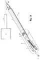
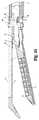
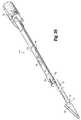
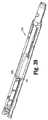
最初に図1Aを参照すると、本開示に従うリロード10が示されている。リロード10は、図1Aに12として概略的に示される多様な異なる外科手術作動デバイスに結合されるように構成され得、このデバイスとしては、手動で動作させられる作動デバイス、ロボットで制御される作動デバイス、電気機械式作動デバイス、動力化作動デバイスなどが挙げられる。外科手術作動デバイス12は、シャフトアセンブリ16を含み、このシャフトアセンブリ16は、リロード10を解放可能に支持するように構成されている遠位端を有する。 Referring initially to FIG. 1A, a reload 10 according to the present disclosure is shown. The reload 10 can be configured to be coupled to a variety of different surgical actuation devices, schematically shown as 12 in FIG. 1A, including manually operated actuation devices, robotic controlled actuation. Devices, electromechanical actuation devices, motorized actuation devices, and the like.
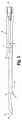
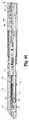
図1Bに例示されている1つの実施形態において、外科手術作動デバイス12は、手動で動作させられるステープラー212であり、この手動で動作させられるステープラー212は、ハンドルアセンブリ214とシャフトアセンブリ216とを含み、このシャフトアセンブリ216は、リロード10を係合し、支持している。ハンドルアセンブリ214は、1対の後退ノブ218を含み、1対の後退ノブ218は、ステープラー212を後退構成に戻すように構成されている。ステープラー212の動作および動作上の構成要素のより詳細な記載について、Millimanに対する共有に係る米国特許第5,865,361号が参照され、その内容全体は、これにより参考として援用される。 In one embodiment illustrated in FIG. 1B, the
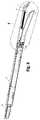
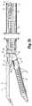
図2は、部品が分離されているリロード10の斜視図である。リロード10は、外側チューブ18を含み、この外側チューブ18は、シャフトアセンブリ20を収容し、このシャフトアセンブリ20は、リロード10を作動デバイス12のシャフトアセンブリ16に結合するように構成されている(図1Aを参照のこと)。シャフトアセンブリ20は、上方ハウジング部分22aと下方ハウジング部分22bとを含み、上方ハウジング部分22aと下方ハウジング部分22bとは、互いに結合された場合、リロード10の構成要素を収容する。上方ハウジング部分22aの近位端24a、および下方ハウジング部分22bの近位端24bは、作動デバイス12(例えば、‘361特許を参照のこと)のシャフトアセンブリ16の遠位端と解放可能に結合するように構成されている。シャフトアセンブリ20のハウジング部分22aの遠位端は、上方結合部材26aを支持し、シャフトアセンブリ20のハウジング部分22bの遠位端は、下方結合部材26bを支持している。結合部材26aの遠位端は、旋回アセンブリ30(図1Aを参照のこと)の上方旋回部分28aを旋回可能に係合するように構成され、結合部材26bの遠位端は、旋回アセンブリ30(図1Aを参照のこと)の下方旋回部分28bを旋回可能に係合するように構成されている。関節運動リンク32は、上方ハウジング部分22aおよび下方ハウジング部分22b内にスライド可能に位置決めされ、リロード10のエンドエフェクターまたはツールアセンブリ14をシャフトアセンブリ20に対して関節運動させるように構成されている。 FIG. 2 is a perspective view of the reload 10 with parts separated. The reload 10 includes an
ツールアセンブリ14は、カートリッジ15を支持している第1の顎部材13と、アンビル19を支持している第2の顎部材17とを含む。第1の顎部材13は、間隔が空けられた位置と接近させられた位置との間を第2の顎部材17に対して旋回可能に支持されている。カートリッジ15は、複数のプッシャー9とファスナー11とを収容する。切開先端19aは、ステープル留めされるべき組織に対してアンビル19の位置決めを容易にするために、アンビル19の遠位端に固定され得る。そのような切開先端19aは、米国特許第8,348,123号に記載され、上記米国特許は、これにより本明細書中で参考として援用される。 The
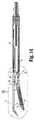
図3〜図6も参照すると、シャフトアセンブリ20は、発射カムバーアセンブリ34を含み、この発射カムバーアセンブリ34は、作動デバイス12の中央ロッド(示されない)と解放可能に係合される。発射カムバーアセンブリ34は、発射カムバーアセンブリ34がツールアセンブリ14を通って遠位方向に並進させられる場合、間隔が空けられた位置(図1B)から接近させられた位置(図18)にカートリッジ15をアンビル19に向かって移動させるように構成されている。発射カムバーアセンブリ34の遠位端はまた、さらに詳細に下に記載されるように、発射カムバーアセンブリ34がカートリッジ15を通って並進させられる場合、複数のプッシャー9を押すことにより、複数のファスナー11をカートリッジ15から発射するように構成されている。 Referring also to FIGS. 3-6, the
発射カムバーアセンブリ34は、第1の発射カムバー36を含み、この第1の発射カムバー36は、左側壁37aおよび右側壁37bによって規定される細長い構成を有し、左側壁37aおよび右側壁37bは、遠位端38を有する。カムバー36の左側壁37aおよび右側壁37bの各々は、カム表面33を含み、このカム表面33は、第1のカム部分39と第2のカム部分40とを有する。第1のカム部分39の各々は、第2のカム部分40のうちの1つに対して遠位方向に、かつある角度で配置されており、この角度は、左側壁37aおよび右側壁37bの底部表面/下方表面に沿って規定される。第2のカム部分40のうちの1つは、図3〜図5において見られ得る。カム表面33の第1のカム部分39の構成は、さらに詳細に下に記載されるように、組織が締め付けられ得るように、第2の顎部材17に向かって、間隔が空けられた位置から接近させられた位置へ第1の顎部材13が移動することを容易にする。第2のカム部分40は、第1のカム部分39に比べて長くされており、発射カムバーアセンブリ34(図5)の近位端に向かって、発射カムバーアセンブリ34の長手方向軸「B−B」に対して内方に距離「T」(図5)だけテーパをつけられている。テーパ「T」は、さらに詳細に下に記載されるように、第1の顎部材13および第2の顎部材17が、接近させられた位置に向かって移動させられる場合、第1の顎部材13と第2の顎部材17との間の組織ギャップの距離を制御する。 The firing
第1の発射カムバー36の遠位端38は、2つのプッシャー接触表面42a、42b(図4および図6)を含み、2つのプッシャー接触表面42a、42bは、カートリッジ15(図19)の複数のプッシャー9と整列させられる。プッシャー接触表面42a、42bは、複数のプッシャー9に接触して、複数の外科手術ファスナー11をカートリッジ15から配備するように構成されている。 The
例示されている実施形態において、発射カムバーアセンブリ34は、第2の発射カムバーまたは内側発射カムバー44を含み、第2の発射カムバーまたは内側発射カムバー44は、第1の発射カムバー36と同様である。第1の発射カムバー36および第2の発射カムバー44は、(図6に最も良好に示されるように)互いに入れ子状の構成を形成する。第2の発射カムバー44は、左側壁45aおよび右側壁45bによって規定される細長い構成を有し、左側壁45aおよび右側壁45bは、遠位端46を有する。カムバー44の左側壁45aおよび右側壁45bの各々は、カム表面53を含み、このカム表面53は、第1のカム部分49と第2のカム部分50とを有する。カム表面53の第1のカム部分49は、カム表面53の第2のカム部分50(第2の部分50のうちの1つのみが示されている)に対して遠位方向に、かつある角度で配置されている。第2の発射カムバー44の遠位端46は、2つのプッシャー接触表面48a、48bを含み、2つのプッシャー接触表面48a、48bは、カートリッジ15の複数のプッシャー9と整列させられ、複数のプッシャー9に接触することにより、複数の外科手術ファスナー11をカートリッジ15から配備する(図19)。 In the illustrated embodiment, the firing
第1の発射カムバー36および第2の発射カムバー44は、任意の適切な材料から形成され得、その材料としては、プラスチック、金属などが挙げられるが、これらに限定されない。実施形態において、第1の発射カムバー36および第2の発射カムバー44は、金属から形成される。 First firing
発射カムバーアセンブリ34は、第1の発射カムバー36および第2の発射カムバー44を含むものとして本明細書中に記載されているが、より多くの発射カムバーまたはより少ない発射カムバーが利用され得る。例えば、実施形態において、第2の発射カムバー44は、省略され得る。この特定の実施形態において、発射カムバーアセンブリ34の第1の発射カムバー36の構成は、第2の発射カムバー44の特徴を含むように改変され得る。例えば、第1の発射カムバー36の左側壁37aおよび右側壁37bは、カートリッジ15内に配置されている複数のファスナー11の全てを射出するために、複数のプッシャー9の列の全てと整列するように遠位端38において広くされている。あるいは、第2の発射カムバー44は、第1の発射カムバー36の構成に対する変更なしで省略され得る。 Although the firing
図7〜図13を参照すると、カンチレバー52(図13)は、第1の顎部材13の近位端において提供されている。カンチレバー52は、第1の顎部材13と一体式に形成され得る。あるいは、カンチレバー52は、第1の顎部材13とは別の別個の構成要素として形成され得、1つ以上の適切な結合方法(例えば、溶接)を介して、第1の顎部材13に結合され得る。カンチレバー52は、下方結合部材26bと関節運動リンク32の遠位端との間に、旋回アセンブリ30に隣接して配置されている(例えば、図9を参照のこと)。 With reference to FIGS. 7-13, a cantilever 52 (FIG. 13) is provided at the proximal end of the
例示されている実施形態において、カンチレバー52は、側面突出部55aと側面突出部55bとの間に形成されているブリッジ54の形態であり、側面突出部55aおよび側面突出部55bは、第1の顎部材13の近位端から近位方向に延びている(図13)。ブリッジ54は、リロード10のシャフトアセンブリ20を通って規定される長手方向軸「A−A」(図7)に対して横方向に配置されている。 In the illustrated embodiment, the
ブリッジ54は、カム部材57(図2および図13)を支持し、このカム部材57は、より詳細に下に記載されるように、発射カムバーアセンブリ34がカートリッジ15内で遠位方向に前進させられる場合、第1の発射カムバー36の第1のカム部分39および第2のカム部分40、ならびに第2の発射カムバー44の第1のカム部分49および第2のカム部分50によってスライド可能に係合されるように位置決めされている。カム部材57は、第1の顎部材13および第2の顎部材17が、接近させられた位置にある場合、第1の顎部材13と第2の顎部材17との間の組織ギャップのサイズを制御するために、(例示されている実施形態に示されるように)傾斜させられ得るか、または他の方法で、第1のカムバー36の第2のカム部分40および第2のカムバー44の第2のカム部分50のテーパ「T」と関連して動作するように構成され得る。カム部材57は、1つ以上の適切な結合方法(例えば、接着剤、溶接など)を介してブリッジ54に結合され得る。あるいは、カム部材57は、省略され得、ブリッジ54は、組織ギャップのサイズを制御するように構成されているカム表面と一体的に形成され得る。本開示に従って、ブリッジ54は、線形位置および関節運動した位置の両方において、発射カムバー36、44を係合して、第1の顎部材13と第2の顎部材17とを閉じる。 The
図9を参照すると、カンチレバー52は、側面突出部55a、55bとブリッジ54との間にアパーチャー58を規定する。アパーチャー58は、リロード10の製造中、下方結合部材26bを旋回アセンブリ30の下方部分28bに結合するためのリベット59(図9)を受け取る。 Referring to FIG. 9, the
図2、図14、および図15を参照すると、弾性部材56が、カートリッジ15上に提供され、弾性部材56は、カートリッジ15を、間隔が空けられた位置に向かって、アンビル19から離れるほうに半径方向に付勢するように位置決めされている。弾性部材56は、カートリッジ15の近位端に結合されている近位端60と、アンビル19の少なくとも一部分に接触するように位置決めされている遠位端62とを含む。例示されている実施形態において、弾性部材56の近位端60は、2つのフィンガー部分64a、64bを含み、2つのフィンガー部分64a、64bは、カートリッジ15の近位端に規定される適切な構成の2つの対応するアパーチャー66a、66bの中に置かれる(図2および図13を参照のこと)。 With reference to FIGS. 2, 14, and 15, an
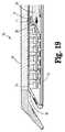
図16および図17を参照すると、使用において、第1の顎部材13と第2の顎部材17との間に組織を位置決めする前、ツールアセンブリ14は、間隔が空けられた位置または接近させられていない位置にある。この位置において、第1の発射カムバー36の遠位端38および第2の発射カムバー44の遠位端46は、複数のプッシャー9および複数のファスナー11の近位に位置決めされている。さらに、この構成において、第1の発射カムバー36の第1のカム部分39(図6も参照のこと)および第2の発射カムバー44の第1のカム部分49(図6も参照のこと)の係合部分は、カム部材57の近位に位置決めされている。上で議論されるように、弾性部材56は、顎部材13を間隔が空けられた位置または接近させられていない位置に押し付けるように位置決めされている。 Referring to FIGS. 16 and 17, in use, prior to positioning tissue between the
図18を参照すると、発射カムバーアセンブリ34が遠位方向に前進させられる場合、第1の発射カムバー36の第1のカム部分39および第2の発射カムバー44の第1のカム部分49は、ブリッジ54のカム部材57を係合し、カートリッジ15を含む第1の顎部材13を第2の顎部材17のアンビル19に向かって旋回させて、カートリッジ15を含む顎部材13を締め付けられた構成または接近させられた構成に移動させる。この例において、カートリッジは、第2の顎部材に旋回可能に取り付けられている。しかし、本明細書中に開示される実施形態のうちの任意のものは、旋回可能に移動可能である第1の顎部材もしくは第2の顎部材、または両方を有し得る。 Referring to FIG. 18, when the firing
図19を参照すると、発射カムバーアセンブリ34の引き続きの遠位方向の並進は、第1の発射カムバー36の遠位端38および第2の発射カムバー44の遠位端46を移動させて複数のプッシャー9と接触させ、カートリッジ15からアンビル19へ複数のファスナー11を連続して射出して、締め付けられている組織をステープル留めする。本開示に従って、発射カムバーアセンブリ34がカートリッジ15を通って並進させられる場合、第1の発射カムバー36の第2のカム部分40および第2の発射カムバー44の第2のカム部分50におけるテーパ「T」(図15)とのブリッジ54上のカム部材57の係合は、顎部材13に対する顎部材17の位置を制御し、所望の組織ギャップの距離を第1の顎部材13と第2の顎部材17との間に選択的に維持する(図20)。本開示に従って、第1の発射カムバー36の第2のカム部分40および第2の発射カムバー44の第2のカム部分50におけるテーパ「T」の程度は、カートリッジ15を通るカムバーアセンブリ34の並進中に、組織ギャップの距離を選択的に制御するために、均一または非均一であり得る。テーパ「T」は、適切または所望の組織ギャップの距離を提供するために、近位方向に、正(positive)または負(negative)のスロープを規定し得ることに留意のこと。 Referring to FIG. 19, subsequent distal translation of the firing
発射カムバーアセンブリ34およびカンチレバー52を含む顎部材13の独特な構成は、カートリッジ15とアンビル19との間の組織ギャップを接近させ、制御するための単純な設計を提供する。さらに、本開示のツールアセンブリ14は、発射カムバーアセンブリ34が前進させられる場合、第1の顎部材13と第2の顎部材17との間の組織ギャップが、第1の発射カムバー36の第2のカム部分40および第2の発射カムバー44の第2のカム部分50によって正確に制御されることを可能する。 The unique configuration of
実施形態において、ツールアセンブリ14は、外科手術作動デバイス12と一体的に形成され得る。この特定の実施形態において、ツールアセンブリ14は、外科手術作動デバイス12のシャフトアセンブリ16の遠位端において支持され得る関節運動アセンブリ(例えば、関節運動アセンブリ30)に動作可能に結合され得る。あるいは、関節運動アセンブリ30は、省略され得、ツールアセンブリ14は、外科手術作動デバイス12のシャフトアセンブリ16の遠位端に直接接続され得る。 In embodiments, the
図21〜図44は、本開示の別の実施形態に従うリロード110を例示している。リロード110は、図1Bに示されるステープラー212との使用のために構成されている。リロード110にとって独特である特徴のみが本明細書中に記載される。 21-44 illustrate a reload 110 according to another embodiment of the present disclosure. The reload 110 is configured for use with the
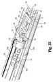
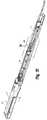
図22は、部品が分離されているリロード110の斜視図である。リロードは、外側チューブ118を含み、この外側チューブ118は、シャフトアセンブリ120を収容し、このシャフトアセンブリ120は、リロード110を図1Bに示される作動デバイス212のシャフトアセンブリ216と結合するように構成されている。シャフトアセンブリ120は、上方ハウジング部分122aと下方ハウジング部分122bとを含み、上方ハウジング部分122aおよび下方ハウジング部分122bは、互いに結合される場合、リロード110の構成要素を収容する。上方ハウジング部分122aの近位端124aおよび下方ハウジング部分122bの近位端124bは、作動デバイス212のシャフトアセンブリ216の遠位端に解放可能に結合するように構成されている(例えば、‘361特許を参照のこと)。シャフトアセンブリ120の遠位端は、1対の上方結合部材126aと下方結合部材126bとを含み、1対の上方結合部材126aおよび下方結合部材126bは、それぞれ、シャフトアセンブリ120を旋回アセンブリ130(図21を参照のこと)の上方旋回部分128aおよび下方旋回部分128bに結合するように構成されている。関節運動リンク132は、上方ハウジング部分122aおよび下方ハウジング部分122b内にスライド可能に位置決めされており、シャフトアセンブリ120を通して規定される長手方向軸「C−C」(図21)に対して、リロード110のエンドエフェクターまたはツールアセンブリ114を関節運動させるように構成されている。 FIG. 22 is a perspective view of the reload 110 with parts separated. The reload includes an
図22〜図24を参照すると、ツールアセンブリ114は、複数のプッシャー109およびファスナー111を収容しているカートリッジ115を支持している第1の顎部材113と、アンビル119を支持している第2の顎部材117とを含む。カートリッジ115は、弾性部材156を支持し、この弾性部材156は、カートリッジ115を、接近させられていない構成または間隔が空けられた構成に向かって、アンビル119から離れるほうに半径方向に付勢するように位置決めされている。弾性部材156は、カートリッジ115の近位端に結合されているベース部分160(図24)と、アンビル119の少なくとも一部分に接触するように位置決めされている上方部分162とを含む。弾性部材156のベース部分160は、カートリッジ115の近位端に規定される対応するスロット165内に置かれ、1つ以上の移動止め163(1つの移動止め163が図面に示されている)を含み、1つ以上の移動止め163は、対応するインデント166の中に受け取られ、この対応するインデント166は、弾性部材156をカートリッジ115に結合するために、スロット165に隣接してカートリッジ115上に配置されている。 Referring to FIGS. 22-24, the
図25および図26を参照すると、第2の顎部材117は、1対の上方レール121a、121bを含み、1対の上方レール121a、121bは、第2の顎部材117の内部壁部分123に沿って長手方向に延びている。上方レール121a、121bは、細長いスロット125によって分離され、この細長いスロット125は、上方レール121a、121bの長さに沿って延びている。上方レール121a、121bは、弾性部材156の頂部部分162が顎部材117の内部壁部分123に接触する場所の近くに、内部壁部分123に沿って位置決めされている(例えば、図35を参照のこと)。切開先端157(例えば、‘123特許に開示される)は、ステープル留めされるべき組織に対する第2の顎部材117の位置決めを容易にするために、第2の顎部材117の遠位端に固定され得る。 Referring to FIGS. 25 and 26, the
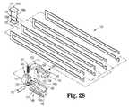
図27および図28も参照すると、リロード110(図21)は、複数の駆動梁部分135から形成されている駆動梁アセンブリ134を含み、複数の駆動梁部分135は、互いに結合されて、駆動梁136を形成する。駆動梁アセンブリ134の作業端は、I−梁137を含み、このI−梁137は、駆動梁部分135の遠位端に結合され、上方フランジ139aと下方フランジ139bとを含み、上方フランジ139aおよび下方フランジ139bは、支柱139cによって互いに接続されている。従来のI−梁と違い、I−梁137は、ステープル留めされた組織を切断するように構成されていないので、I−梁137は、支柱139cの前縁において、ナイフまたは切断刃を含まない。I−梁137は、さらに詳細に下に記載されるように、第1の顎部材113と第2の顎部材117とを接近させて、ファスナー111をカートリッジ115から射出するために、ツールアセンブリ114を通って並進可能である。上方フランジ139aは、第2の顎部材117(図26)内で上方レール121a、121bの上に位置決めされる。駆動梁アセンブリ134の駆動梁136が第2の顎部材117内で遠位方向に並進させられる場合、上方フランジ139aは、上方レール121a、121bの上にスライドして、第1の顎部材113に対する第2の顎部材117の外方への移動を防止する。同様に、I−梁の支柱139cは、第2の顎部材117に対する第1の顎部材113の外方への移動を防止するために、下方フランジ139bが第1の顎部材113の外部表面に沿ってスライド可能であるように、第1の顎部材113を通して規定される細長いスロット127(図31を参照のこと)を通って位置決めされている。切欠き129が、支柱139cの側壁を通して規定され、その重要性は、より詳細に下に記載される。 Referring also to FIGS. 27 and 28, reload 110 (FIG. 21) includes a
ラッチアセンブリ140は、駆動梁アセンブリ134の近位端に結合されている。ラッチアセンブリ140は、カラー142を含むラッチ本体141を含み、このカラー142は、底部スロットと頂部スロット144(頂部スロット144のみが示されている)とを規定する。スロット144は、駆動梁136の近位端を受け取るように構成されている。適切な構成の長手方向アパーチャー146が、カラー142を通って規定され、ラッチ本体141の細長い近位部分148とほぼ整列している。ラッチアセンブリ140のラッチ本体141は、1対の対向する支持部材149a、149bを含み、1対の対向する支持部材149a、149bは、旋回ピン151を支持する。突出部170が、カラー142に隣接して、ラッチアセンブリ140のラッチ本体から上方に延び、ばね171を支持するように構成されている。
ラッチアセンブリ140は、ラッチ150を含み、このラッチ150は、ほぼ細長い構成を有し、遠位部分152と、中間部分154と、近位部分158とを含む。横断アパーチャー153が、中間部分154を通って延びており、ラッチ150をラッチアセンブリ140のラッチ本体141に旋回可能に固定するための旋回ピン151を受け取るように構成されている。ラッチ150の遠位部分152は、(図27に最も良好に示されるように)ばね171がラッチ150の近位部分158の近位端172をラッチアセンブリ140の近位部分148に向かって下方に押し付けるように、ばね171に接触するように位置決めされている。突出部164が、ラッチアセンブリ150の近位部分158の近位端172において、底部表面上に提供されている。側方オフセット延長部分173もラッチアセンブリ150の近位端172に提供され、より詳細に下に記載されるように、ラッチ150をばね171の付勢に対抗して上方に移動させるために構成されている。 The
図29および図30を参照すると、そりプッシャーアセンブリ174が例示されている。そりプッシャーアセンブリ174は、細長い支持部材176を含み、この細長い支持部材176は、そりプッシャー178を係合している遠位端と、結合アセンブリ180を支持している近位端とを有する。支持部材176の遠位端は、スリット181と、1対のアパーチャー182(1つのアパーチャー182のみが示されている)とを規定する。アパーチャー182は、スリット181を通って延びており、ピン183、リベットなどを受け取る。スリット181は、そりプッシャー178の近位端を受け取るように構成されている。ピン183は、そりプッシャー178を支持部材176に固定するために、そりプッシャー178の近位端を通って規定されるアパーチャー186を通って延びている。認識され得るように、他の結合方法も、そりプッシャー178を支持部材176に結合するために利用され得る。 Referring to FIGS. 29 and 30, a
アパーチャー184が、支持部材176上に提供されている。アパーチャー184は、アパーチャー184を規定する近位壁部分185に突出部164が接触するように、ラッチ150の突出部164を受け取るように構成されている(図33)。本開示に従って、突出部164が近位壁部分185と接触している場合、そりプッシャーアセンブリ174および駆動梁アセンブリ134は、互いに解放可能に結合されており、その結果、そりプッシャーアセンブリ174の移動は、駆動梁アセンブリ134の対応する移動をもたらし、第2の顎部材117に向かう第1の顎部材113の移動をもたらす。 An
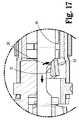
図32および図33も参照すると、下方ハウジング部分122bは、駆動アセンブリ134を支持し、この駆動アセンブリ134は、ラッチアセンブリ140とそりプッシャーアセンブリ174とを含む。下方ハウジング部分122bは、そりプッシャーアセンブリ174からラッチアセンブリ140のラッチ150を係合解除して、駆動梁アセンブリ134から独立した、そりプッシャーアセンブリ174のさらなる遠位方向の並進を可能にするように構成されている。特に、傾斜部分188が、下方ハウジング部分122bの頂部壁189に沿って提供されている。傾斜部分188は、駆動梁アセンブリ134およびそりプッシャーアセンブリ174が遠位方向に並進させられて、顎部材113と顎部材117とを接近させる場合に、ラッチ150の側方オフセット延長部分173に接触して、ラッチ150を旋回部材151の周りで旋回させ、ラッチ150の突出部164を持ち上げて、そりプッシャーアセンブリ174の支持部材176のアパーチャー184との係合からはずすように構成されている。 Referring also to FIGS. 32 and 33, the
1対の停止部190aが、下方ハウジング部分122bの内部壁部分191に沿って提供されている。停止部190aは、カラー142が停止部190aを係合した後、駆動梁アセンブリ134のさらなる遠位方向の並進を防止するために、ラッチアセンブリ140のカラー142の下方部分に接触するように位置決めされている。例示されている実施形態において、対応する1対の停止部190b(図39)が、上方ハウジング部分122aに提供され、カラー142が停止部190aを係合した後、駆動梁アセンブリ134のさらなる遠位方向の並進を防止するために、ラッチアセンブリ140のカラー142の上方部分に接触するように構成されている。 A pair of
図34〜図44は、リロード110の動作を例示している。図33〜図35を参照すると、第1の顎部材113と第2の顎部材117との間に組織を位置決めする前、ツールアセンブリ114は、第2の顎部材117の内部壁123に接触している弾性部材156によって、間隔が空けられた位置または接近させられていない位置に押し付けられている(図34および図35)。間隔が空けられた位置において、ラッチ150の突出部164は、支持部材176におけるアパーチャー184を規定する近位壁部分185と接触して、そりプッシャーアセンブリ174を駆動梁アセンブリ134に解放可能に結合し、その結果、そりプッシャーアセンブリ174の遠位方向の並進は、駆動梁アセンブリ134の対応する移動をもたらす。 34 to 44 illustrate the operation of the reload 110. Referring to FIGS. 33-35, the
顎部材113および117の間隔が空けられた位置において、支持部材176の遠位端は、ラッチアセンブリ140のカラー142の長手方向アパーチャー146を通って位置決めされ、そりプッシャー178は、そりプッシャー178の遠位端193をカートリッジ115(図35)中に提供されるそり187と整列させるために、I−梁137の支柱139cの切欠き129内に位置決めされる。そりプッシャー178の遠位端193は、そりプッシャー178がカートリッジ115の中へ遠位方向に並進させられる場合、そり187の近位端195を係合するように構成されている。例示されている実施形態において、そりプッシャー178の遠位端193およびそり187の近位端195は、それらの間の係合を容易にするために、相補的な構成(例えば、丸い構成)を含む。そり187は、当該分野において公知であるように、複数のプッシャー109に連続して接触して、複数のファスナー111をカートリッジ115から射出するように構成されている。 In the spaced position of the
図36〜図41を参照すると、外科手術作動デバイス12(図1B)がそりプッシャーアセンブリ174を前進させるように作動させられる場合、そりプッシャーアセンブリ174に解放可能に結合されている駆動アセンブリ134は、遠位方向に前進させられて、I−梁137をツールアセンブリ114に対して遠位方向に移動させる。I−梁が遠位方向に移動させられる場合、I−梁137の上方フランジ139aは、第2の顎部材117を係合し、I−梁137の下方フランジ139bは、第1の顎部材113を係合し、その結果、第1の顎部材113は、ツールアセンブリ114の締め付けられた位置または接近させられた位置まで第2の顎部材117に向かって移動させられて、組織を締め付ける(図36)。上で言及されるように、駆動アセンブリ134およびそりプッシャーアセンブリ174は、突出部164が支持部材176のアパーチャー184を規定する近位壁部分185と接触している結果として、一斉に移動する。 36-41, when the surgical actuation device 12 (FIG. 1B) is actuated to advance the
駆動アセンブリ134が遠位方向に移動させられて、顎部材113および117を締め付けられた位置または接近させられた位置に移動させる場合、ラッチ150の側方オフセット173(図38)は、下方ハウジング部分122bの傾斜188に沿って上方にスライドし、ラッチ150を持ち上げて、支持部材176の近位壁部分185との係合からラッチ140の突出部164を係合解除する。顎部材113および117の接近させられた位置において、そりプッシャーアセンブリ174は、駆動アセンブリ134から結合解除され、そりプッシャー178の遠位端193は、(図41に最も良好に示されるように)そり187の近位端195との係合に位置決めされる。 When the
接近させられた位置において、カラー142は、下方ハウジング部分122bにおける停止部190aと接触しており(図38および図42)、カラー142の上方部分は、上方ハウジング部分122aにおける停止部190bと接触している。停止部190aとカラー142との間の係合は、駆動梁アセンブリ134のさらなる遠位方向の移動を防止する。 In the approximated position,
図42〜図44を参照すると、そりプッシャーアセンブリ174が駆動アセンブリ134から結合解除された後、作動デバイス12のさらなる作動は、カラー142のアパーチャー146を通したそりプッシャーアセンブリ174の独立した移動をもたらし、その結果、そりプッシャー178の遠位端193は、駆動アセンブリ134のI−梁137に対して遠位方向に移動して、カートリッジ115を通してそり187を前進させて、プッシャー109と連続的に係合させて、複数のファスナー111をカートリッジ115から射出する(図43および図44)。 42-44, after the
リロード10、110は、ステープラー212との使用のために構成されているものとして本明細書中に記載されているが、リロード10、110の動作上の構成要素が、ステープラーに固定して取り付けられているツールアセンブリを有するステープラーに組み込まれ得ることは、本開示の範囲内である。 Although reloads 10, 110 are described herein as being configured for use with
ステープラーに取り付けられているリロード10、110のいずれかを有するステープラー212は、様々な組織構造をステープル留めするために利用され得る。例えば、移植部位に隣接した脈管構造を通る血流が、制御される必要があるか、または抑制される必要がある移植手順中、ステープラー212は、この脈管構造をステープル留めする(すなわち、塞ぐ)ために利用され得、それにより、脈管構造を通る血流を制御し、かつ/または抑制する。ステープラー212に取り付けられているリロード10、110のいずれかを有するステープラー212が、他のタイプの組織構造をステープル留めするために利用され得ること、および/または他の外科手術手順とともに利用され得ることが企図される。 A
本開示のいつくかの実施形態が図面に示されてきたが、本開示は当該分野が許容するのと同じほど範囲が広いこと、および本明細書は同様に読まれることが意図されるので、本開示はそれらの実施形態に限定されることが意図されない。従って、上の記載は、限定するものではなく、単に特定の実施形態の例証と解釈されるべきである。当業者は、本明細書に添付される特許請求の範囲の趣旨および範囲内の他の改変を想定する。 Although several embodiments of the present disclosure have been shown in the drawings, the present disclosure is as broad as the field allows and the specification is intended to be read similarly. The present disclosure is not intended to be limited to those embodiments. Therefore, the above description should not be construed as limiting, but merely as exemplifications of particular embodiments. Those skilled in the art will envision other modifications within the scope and spirit of the claims appended hereto.
Claims (21)
Translated fromJapanese細長いシャフトを含む作動デバイスと、
該シャフトの遠位端に配置されているツールアセンブリであって、該ツールアセンブリは、カートリッジアセンブリを支持している第1の顎部材であって、該カートリッジアセンブリは、複数の外科手術ファスナーを有する、第1の顎部材と、アンビルを支持している第2の顎部材とを含み、該第1の顎部材は、間隔が空けられた位置と接近させられた位置との間を該第2の顎部材に対して移動可能であり、該第1の顎部材は、その近位端においてカンチレバーを含む、ツールアセンブリと、
長手方向軸を規定する発射カムバーアセンブリであって、該ツールアセンブリ内にスライド可能に配置されている発射カムバーアセンブリと
を含み、該発射カムバーアセンブリは、第1のカム部分および第2のカム部分を有するカム表面含み、該第2のカム部分は、該第1のカム部分から延在し、該長手方向軸に対するテーパを含み、該カム表面は、該カンチレバーを係合して該第1の顎部材を該接近させられた位置に向かって該第2の顎部材に対して移動させるように構成され、該第2のカム部分の該テーパは、該接近させられた位置における該第1の顎部材と該第2の顎部材との間のギャップの距離を決定し、該発射カムバーアセンブリは、該発射カムバーアセンブリが該ツールアセンブリを通って遠位方向に並進させられる場合、該カートリッジアセンブリから該複数の外科手術ファスナーを配備するように構成されている遠位端を含む、外科手術ステープル留め装置。Surgical stapling apparatus, the surgical stapling apparatus comprising:
An actuation device including an elongated shaft;
A tool assembly disposed at a distal end of the shaft, the tool assembly being a first jaw member supporting a cartridge assembly, the cartridge assembly having a plurality of surgical fasteners. , A first jaw member and a second jaw member supporting the anvil, the first jaw member between the spaced and approximated positions. is movable relative to the jaw member, the first jaw memberincludes a cantilever at its proximal end, a tool assembly,
A firing cam bar assembly defining a longitudinal axis , wherein the firing cam bar assembly is slidably disposed within the tool assembly, the firing cam bar assembly including afirst cam portion and a second cam portion. A cam surface having a cam portion, wherein the second cam portion extends from the first cam portion and includes a taper with respect to the longitudinal axis, the cam surface engaging the cantilever and A jaw memberis configuredto moverelative to the second jaw member toward theapproximated position,wherein the taper of the second cam portion includes the first taper in the approximated position. Determining the distance of the gap between one jaw member and the second jaw member, and when the firing cam bar assembly is translated distally through the tool assembly, The It includesa distal end that is configured to deploy the plurality of surgical fasteners from the chromatography cartridge assembly, surgical stapling device.
近位端と遠位端とを含むシャフトであって、該近位端は、外科手術装置に結合するように適合されている、シャフトと、
該シャフトの該遠位端に配置されているツールアセンブリであって、該ツールアセンブリは、カートリッジアセンブリを支持している第1の顎部材であって、該カートリッジアセンブリは、複数の外科手術ファスナーを有する、第1の顎部材と、アンビルを支持している第2の顎部材とを含み、該第1の顎部材は、間隔が空けられた位置と接近させられた位置との間を該第2の顎部材に対して移動可能であり、該第1の顎部材は、その近位端においてカンチレバーを含む、ツールアセンブリと、
長手方向軸を規定する発射カムバーアセンブリであって、該ツールアセンブリ内にスライド可能に配置されている発射カムバーアセンブリと
を含み、該発射カムバーアセンブリは、第1のカム部分および第2のカム部分を有するカム表面含み、該第2のカム部分は、該第1のカム部分から延在し、該長手方向軸に対するテーパを含み、該カム表面は、該カンチレバーを係合して該第1の顎部材を該接近させられた位置に向かって該第2の顎部材に対して移動させるように構成され、該第2のカム部分の該テーパは、該接近させられた位置における該第1の顎部材と該第2の顎部材との間のギャップの距離を決定し、該発射カムバーアセンブリは、該発射カムバーアセンブリが該ツールアセンブリを通って遠位方向に並進させられる場合、該カートリッジアセンブリから該複数の外科手術ファスナーを配備するように構成されている遠位端を含む、リロード。A reload configured for use with a surgical stapling apparatus, the reload comprising:
A shaft including a proximal end and a distal end, wherein the proximal end is adapted to couple to a surgical device;
A tool assembly disposed at the distal end of the shaft, the tool assembly being a first jaw member supporting a cartridge assembly, the cartridge assembly comprising a plurality of surgical fasteners; A first jaw member and a second jaw member supporting the anvil, the first jaw member between the spaced and approximated positions. is movable relative to the second jaw member, the first jaw memberincludes a cantilever at its proximal end, a tool assembly,
A firing cam bar assembly defining a longitudinal axis , wherein the firing cam bar assembly is slidably disposed within the tool assembly, the firing cam bar assembly including afirst cam portion and a second cam portion. A cam surface having a cam portion, wherein the second cam portion extends from the first cam portion and includes a taper with respect to the longitudinal axis, the cam surface engaging the cantilever and A jaw memberis configuredto moverelative to the second jaw member toward theapproximated position,wherein the taper of the second cam portion includes the first taper in the approximated position. Determining the distance of the gap between one jaw member and the second jaw member, and when the firing cam bar assembly is translated distally through the tool assembly, The It includesa distal end that is configured to deploy the plurality of surgical fasteners from the cartridgesassembly, reload.
Applications Claiming Priority (2)
| Application Number | Priority Date | Filing Date | Title |
|---|---|---|---|
| US14/166,294US9629627B2 (en) | 2014-01-28 | 2014-01-28 | Surgical apparatus |
| US14/166,294 | 2014-01-28 |
Related Child Applications (1)
| Application Number | Title | Priority Date | Filing Date |
|---|---|---|---|
| JP2018240854ADivisionJP2019088799A (en) | 2014-01-28 | 2018-12-25 | Surgical apparatus |
Publications (2)
| Publication Number | Publication Date |
|---|---|
| JP2015139703A JP2015139703A (en) | 2015-08-03 |
| JP6497931B2true JP6497931B2 (en) | 2019-04-10 |
Family
ID=52231968
Family Applications (2)
| Application Number | Title | Priority Date | Filing Date |
|---|---|---|---|
| JP2014260009AActiveJP6497931B2 (en) | 2014-01-28 | 2014-12-24 | Surgical equipment |
| JP2018240854APendingJP2019088799A (en) | 2014-01-28 | 2018-12-25 | Surgical apparatus |
Family Applications After (1)
| Application Number | Title | Priority Date | Filing Date |
|---|---|---|---|
| JP2018240854APendingJP2019088799A (en) | 2014-01-28 | 2018-12-25 | Surgical apparatus |
Country Status (6)
| Country | Link |
|---|---|
| US (2) | US9629627B2 (en) |
| EP (1) | EP2898839B1 (en) |
| JP (2) | JP6497931B2 (en) |
| CN (1) | CN104799899B (en) |
| AU (2) | AU2014259548B2 (en) |
| CA (1) | CA2868736A1 (en) |
Families Citing this family (448)
| Publication number | Priority date | Publication date | Assignee | Title |
|---|---|---|---|---|
| US9060770B2 (en) | 2003-05-20 | 2015-06-23 | Ethicon Endo-Surgery, Inc. | Robotically-driven surgical instrument with E-beam driver |
| US20070084897A1 (en) | 2003-05-20 | 2007-04-19 | Shelton Frederick E Iv | Articulating surgical stapling instrument incorporating a two-piece e-beam firing mechanism |
| US9072535B2 (en) | 2011-05-27 | 2015-07-07 | Ethicon Endo-Surgery, Inc. | Surgical stapling instruments with rotatable staple deployment arrangements |
| US8215531B2 (en) | 2004-07-28 | 2012-07-10 | Ethicon Endo-Surgery, Inc. | Surgical stapling instrument having a medical substance dispenser |
| US11998198B2 (en) | 2004-07-28 | 2024-06-04 | Cilag Gmbh International | Surgical stapling instrument incorporating a two-piece E-beam firing mechanism |
| US11890012B2 (en) | 2004-07-28 | 2024-02-06 | Cilag Gmbh International | Staple cartridge comprising cartridge body and attached support |
| US7934630B2 (en) | 2005-08-31 | 2011-05-03 | Ethicon Endo-Surgery, Inc. | Staple cartridges for forming staples having differing formed staple heights |
| US10159482B2 (en) | 2005-08-31 | 2018-12-25 | Ethicon Llc | Fastener cartridge assembly comprising a fixed anvil and different staple heights |
| US9237891B2 (en) | 2005-08-31 | 2016-01-19 | Ethicon Endo-Surgery, Inc. | Robotically-controlled surgical stapling devices that produce formed staples having different lengths |
| US11246590B2 (en) | 2005-08-31 | 2022-02-15 | Cilag Gmbh International | Staple cartridge including staple drivers having different unfired heights |
| US11484312B2 (en) | 2005-08-31 | 2022-11-01 | Cilag Gmbh International | Staple cartridge comprising a staple driver arrangement |
| US7669746B2 (en) | 2005-08-31 | 2010-03-02 | Ethicon Endo-Surgery, Inc. | Staple cartridges for forming staples having differing formed staple heights |
| US20070106317A1 (en) | 2005-11-09 | 2007-05-10 | Shelton Frederick E Iv | Hydraulically and electrically actuated articulation joints for surgical instruments |
| US8186555B2 (en) | 2006-01-31 | 2012-05-29 | Ethicon Endo-Surgery, Inc. | Motor-driven surgical cutting and fastening instrument with mechanical closure system |
| US11224427B2 (en) | 2006-01-31 | 2022-01-18 | Cilag Gmbh International | Surgical stapling system including a console and retraction assembly |
| US20110024477A1 (en) | 2009-02-06 | 2011-02-03 | Hall Steven G | Driven Surgical Stapler Improvements |
| US11793518B2 (en) | 2006-01-31 | 2023-10-24 | Cilag Gmbh International | Powered surgical instruments with firing system lockout arrangements |
| US7753904B2 (en) | 2006-01-31 | 2010-07-13 | Ethicon Endo-Surgery, Inc. | Endoscopic surgical instrument with a handle that can articulate with respect to the shaft |
| US20120292367A1 (en) | 2006-01-31 | 2012-11-22 | Ethicon Endo-Surgery, Inc. | Robotically-controlled end effector |
| US8820603B2 (en) | 2006-01-31 | 2014-09-02 | Ethicon Endo-Surgery, Inc. | Accessing data stored in a memory of a surgical instrument |
| US11278279B2 (en) | 2006-01-31 | 2022-03-22 | Cilag Gmbh International | Surgical instrument assembly |
| US7845537B2 (en) | 2006-01-31 | 2010-12-07 | Ethicon Endo-Surgery, Inc. | Surgical instrument having recording capabilities |
| US20110295295A1 (en) | 2006-01-31 | 2011-12-01 | Ethicon Endo-Surgery, Inc. | Robotically-controlled surgical instrument having recording capabilities |
| US8708213B2 (en) | 2006-01-31 | 2014-04-29 | Ethicon Endo-Surgery, Inc. | Surgical instrument having a feedback system |
| US8992422B2 (en) | 2006-03-23 | 2015-03-31 | Ethicon Endo-Surgery, Inc. | Robotically-controlled endoscopic accessory channel |
| US8322455B2 (en) | 2006-06-27 | 2012-12-04 | Ethicon Endo-Surgery, Inc. | Manually driven surgical cutting and fastening instrument |
| US10568652B2 (en) | 2006-09-29 | 2020-02-25 | Ethicon Llc | Surgical staples having attached drivers of different heights and stapling instruments for deploying the same |
| US11980366B2 (en) | 2006-10-03 | 2024-05-14 | Cilag Gmbh International | Surgical instrument |
| US8684253B2 (en) | 2007-01-10 | 2014-04-01 | Ethicon Endo-Surgery, Inc. | Surgical instrument with wireless communication between a control unit of a robotic system and remote sensor |
| US11291441B2 (en) | 2007-01-10 | 2022-04-05 | Cilag Gmbh International | Surgical instrument with wireless communication between control unit and remote sensor |
| US8632535B2 (en) | 2007-01-10 | 2014-01-21 | Ethicon Endo-Surgery, Inc. | Interlock and surgical instrument including same |
| US11039836B2 (en) | 2007-01-11 | 2021-06-22 | Cilag Gmbh International | Staple cartridge for use with a surgical stapling instrument |
| US20080169333A1 (en) | 2007-01-11 | 2008-07-17 | Shelton Frederick E | Surgical stapler end effector with tapered distal end |
| US7673782B2 (en) | 2007-03-15 | 2010-03-09 | Ethicon Endo-Surgery, Inc. | Surgical stapling instrument having a releasable buttress material |
| US11564682B2 (en) | 2007-06-04 | 2023-01-31 | Cilag Gmbh International | Surgical stapler device |
| US8931682B2 (en) | 2007-06-04 | 2015-01-13 | Ethicon Endo-Surgery, Inc. | Robotically-controlled shaft based rotary drive systems for surgical instruments |
| US7753245B2 (en) | 2007-06-22 | 2010-07-13 | Ethicon Endo-Surgery, Inc. | Surgical stapling instruments |
| US11849941B2 (en) | 2007-06-29 | 2023-12-26 | Cilag Gmbh International | Staple cartridge having staple cavities extending at a transverse angle relative to a longitudinal cartridge axis |
| US9179912B2 (en) | 2008-02-14 | 2015-11-10 | Ethicon Endo-Surgery, Inc. | Robotically-controlled motorized surgical cutting and fastening instrument |
| JP5410110B2 (en) | 2008-02-14 | 2014-02-05 | エシコン・エンド−サージェリィ・インコーポレイテッド | Surgical cutting / fixing instrument with RF electrode |
| US7866527B2 (en) | 2008-02-14 | 2011-01-11 | Ethicon Endo-Surgery, Inc. | Surgical stapling apparatus with interlockable firing system |
| US8758391B2 (en) | 2008-02-14 | 2014-06-24 | Ethicon Endo-Surgery, Inc. | Interchangeable tools for surgical instruments |
| US8573465B2 (en) | 2008-02-14 | 2013-11-05 | Ethicon Endo-Surgery, Inc. | Robotically-controlled surgical end effector system with rotary actuated closure systems |
| US7819298B2 (en) | 2008-02-14 | 2010-10-26 | Ethicon Endo-Surgery, Inc. | Surgical stapling apparatus with control features operable with one hand |
| US8636736B2 (en) | 2008-02-14 | 2014-01-28 | Ethicon Endo-Surgery, Inc. | Motorized surgical cutting and fastening instrument |
| US11986183B2 (en) | 2008-02-14 | 2024-05-21 | Cilag Gmbh International | Surgical cutting and fastening instrument comprising a plurality of sensors to measure an electrical parameter |
| US9585657B2 (en) | 2008-02-15 | 2017-03-07 | Ethicon Endo-Surgery, Llc | Actuator for releasing a layer of material from a surgical end effector |
| US8210411B2 (en) | 2008-09-23 | 2012-07-03 | Ethicon Endo-Surgery, Inc. | Motor-driven surgical cutting instrument |
| US11648005B2 (en) | 2008-09-23 | 2023-05-16 | Cilag Gmbh International | Robotically-controlled motorized surgical instrument with an end effector |
| US9005230B2 (en) | 2008-09-23 | 2015-04-14 | Ethicon Endo-Surgery, Inc. | Motorized surgical instrument |
| US9386983B2 (en) | 2008-09-23 | 2016-07-12 | Ethicon Endo-Surgery, Llc | Robotically-controlled motorized surgical instrument |
| US8608045B2 (en) | 2008-10-10 | 2013-12-17 | Ethicon Endo-Sugery, Inc. | Powered surgical cutting and stapling apparatus with manually retractable firing system |
| US8517239B2 (en) | 2009-02-05 | 2013-08-27 | Ethicon Endo-Surgery, Inc. | Surgical stapling instrument comprising a magnetic element driver |
| RU2525225C2 (en) | 2009-02-06 | 2014-08-10 | Этикон Эндо-Серджери, Инк. | Improvement of drive surgical suturing instrument |
| US8220688B2 (en) | 2009-12-24 | 2012-07-17 | Ethicon Endo-Surgery, Inc. | Motor-driven surgical cutting instrument with electric actuator directional control assembly |
| US8851354B2 (en) | 2009-12-24 | 2014-10-07 | Ethicon Endo-Surgery, Inc. | Surgical cutting instrument that analyzes tissue thickness |
| US8783543B2 (en) | 2010-07-30 | 2014-07-22 | Ethicon Endo-Surgery, Inc. | Tissue acquisition arrangements and methods for surgical stapling devices |
| US9386988B2 (en) | 2010-09-30 | 2016-07-12 | Ethicon End-Surgery, LLC | Retainer assembly including a tissue thickness compensator |
| US11812965B2 (en) | 2010-09-30 | 2023-11-14 | Cilag Gmbh International | Layer of material for a surgical end effector |
| US11925354B2 (en) | 2010-09-30 | 2024-03-12 | Cilag Gmbh International | Staple cartridge comprising staples positioned within a compressible portion thereof |
| US9016542B2 (en) | 2010-09-30 | 2015-04-28 | Ethicon Endo-Surgery, Inc. | Staple cartridge comprising compressible distortion resistant components |
| US11298125B2 (en) | 2010-09-30 | 2022-04-12 | Cilag Gmbh International | Tissue stapler having a thickness compensator |
| US12213666B2 (en) | 2010-09-30 | 2025-02-04 | Cilag Gmbh International | Tissue thickness compensator comprising layers |
| US9788834B2 (en) | 2010-09-30 | 2017-10-17 | Ethicon Llc | Layer comprising deployable attachment members |
| US10945731B2 (en) | 2010-09-30 | 2021-03-16 | Ethicon Llc | Tissue thickness compensator comprising controlled release and expansion |
| US9629814B2 (en) | 2010-09-30 | 2017-04-25 | Ethicon Endo-Surgery, Llc | Tissue thickness compensator configured to redistribute compressive forces |
| US9351730B2 (en) | 2011-04-29 | 2016-05-31 | Ethicon Endo-Surgery, Llc | Tissue thickness compensator comprising channels |
| US8695866B2 (en) | 2010-10-01 | 2014-04-15 | Ethicon Endo-Surgery, Inc. | Surgical instrument having a power control circuit |
| AU2012250197B2 (en) | 2011-04-29 | 2017-08-10 | Ethicon Endo-Surgery, Inc. | Staple cartridge comprising staples positioned within a compressible portion thereof |
| US11207064B2 (en) | 2011-05-27 | 2021-12-28 | Cilag Gmbh International | Automated end effector component reloading system for use with a robotic system |
| US9168042B2 (en)* | 2012-01-12 | 2015-10-27 | Covidien Lp | Circular stapling instruments |
| US9044230B2 (en) | 2012-02-13 | 2015-06-02 | Ethicon Endo-Surgery, Inc. | Surgical cutting and fastening instrument with apparatus for determining cartridge and firing motion status |
| MX358135B (en) | 2012-03-28 | 2018-08-06 | Ethicon Endo Surgery Inc | Tissue thickness compensator comprising a plurality of layers. |
| JP6224070B2 (en) | 2012-03-28 | 2017-11-01 | エシコン・エンド−サージェリィ・インコーポレイテッドEthicon Endo−Surgery,Inc. | Retainer assembly including tissue thickness compensator |
| BR112014024098B1 (en) | 2012-03-28 | 2021-05-25 | Ethicon Endo-Surgery, Inc. | staple cartridge |
| US9101358B2 (en) | 2012-06-15 | 2015-08-11 | Ethicon Endo-Surgery, Inc. | Articulatable surgical instrument comprising a firing drive |
| US9289256B2 (en) | 2012-06-28 | 2016-03-22 | Ethicon Endo-Surgery, Llc | Surgical end effectors having angled tissue-contacting surfaces |
| US12383267B2 (en) | 2012-06-28 | 2025-08-12 | Cilag Gmbh International | Robotically powered surgical device with manually-actuatable reversing system |
| JP6290201B2 (en) | 2012-06-28 | 2018-03-07 | エシコン・エンド−サージェリィ・インコーポレイテッドEthicon Endo−Surgery,Inc. | Lockout for empty clip cartridge |
| US9282974B2 (en) | 2012-06-28 | 2016-03-15 | Ethicon Endo-Surgery, Llc | Empty clip cartridge lockout |
| US9408606B2 (en) | 2012-06-28 | 2016-08-09 | Ethicon Endo-Surgery, Llc | Robotically powered surgical device with manually-actuatable reversing system |
| US20140001231A1 (en) | 2012-06-28 | 2014-01-02 | Ethicon Endo-Surgery, Inc. | Firing system lockout arrangements for surgical instruments |
| US11278284B2 (en) | 2012-06-28 | 2022-03-22 | Cilag Gmbh International | Rotary drive arrangements for surgical instruments |
| BR112014032776B1 (en) | 2012-06-28 | 2021-09-08 | Ethicon Endo-Surgery, Inc | SURGICAL INSTRUMENT SYSTEM AND SURGICAL KIT FOR USE WITH A SURGICAL INSTRUMENT SYSTEM |
| RU2672520C2 (en) | 2013-03-01 | 2018-11-15 | Этикон Эндо-Серджери, Инк. | Hingedly turnable surgical instruments with conducting ways for signal transfer |
| BR112015021082B1 (en) | 2013-03-01 | 2022-05-10 | Ethicon Endo-Surgery, Inc | surgical instrument |
| US9808244B2 (en) | 2013-03-14 | 2017-11-07 | Ethicon Llc | Sensor arrangements for absolute positioning system for surgical instruments |
| US9629629B2 (en) | 2013-03-14 | 2017-04-25 | Ethicon Endo-Surgey, LLC | Control systems for surgical instruments |
| BR112015026109B1 (en) | 2013-04-16 | 2022-02-22 | Ethicon Endo-Surgery, Inc | surgical instrument |
| US9826976B2 (en) | 2013-04-16 | 2017-11-28 | Ethicon Llc | Motor driven surgical instruments with lockable dual drive shafts |
| MX369362B (en) | 2013-08-23 | 2019-11-06 | Ethicon Endo Surgery Llc | Firing member retraction devices for powered surgical instruments. |
| US9775609B2 (en) | 2013-08-23 | 2017-10-03 | Ethicon Llc | Tamper proof circuit for surgical instrument battery pack |
| US9629627B2 (en) | 2014-01-28 | 2017-04-25 | Coviden Lp | Surgical apparatus |
| US9962161B2 (en) | 2014-02-12 | 2018-05-08 | Ethicon Llc | Deliverable surgical instrument |
| US20150272580A1 (en) | 2014-03-26 | 2015-10-01 | Ethicon Endo-Surgery, Inc. | Verification of number of battery exchanges/procedure count |
| US12232723B2 (en) | 2014-03-26 | 2025-02-25 | Cilag Gmbh International | Systems and methods for controlling a segmented circuit |
| BR112016021943B1 (en) | 2014-03-26 | 2022-06-14 | Ethicon Endo-Surgery, Llc | SURGICAL INSTRUMENT FOR USE BY AN OPERATOR IN A SURGICAL PROCEDURE |
| US10013049B2 (en) | 2014-03-26 | 2018-07-03 | Ethicon Llc | Power management through sleep options of segmented circuit and wake up control |
| US10004497B2 (en) | 2014-03-26 | 2018-06-26 | Ethicon Llc | Interface systems for use with surgical instruments |
| US10327764B2 (en) | 2014-09-26 | 2019-06-25 | Ethicon Llc | Method for creating a flexible staple line |
| US10470768B2 (en) | 2014-04-16 | 2019-11-12 | Ethicon Llc | Fastener cartridge including a layer attached thereto |
| US20150297225A1 (en) | 2014-04-16 | 2015-10-22 | Ethicon Endo-Surgery, Inc. | Fastener cartridges including extensions having different configurations |
| CN106456176B (en) | 2014-04-16 | 2019-06-28 | 伊西康内外科有限责任公司 | Fastener Cartridge Including Extensions With Different Configurations |
| BR112016023825B1 (en) | 2014-04-16 | 2022-08-02 | Ethicon Endo-Surgery, Llc | STAPLE CARTRIDGE FOR USE WITH A SURGICAL STAPLER AND STAPLE CARTRIDGE FOR USE WITH A SURGICAL INSTRUMENT |
| CN106456159B (en) | 2014-04-16 | 2019-03-08 | 伊西康内外科有限责任公司 | Fastener Cartridge Assembly and Nail Retainer Cover Arrangement |
| US9788835B2 (en) | 2014-09-02 | 2017-10-17 | Ethicon Llc | Devices and methods for facilitating ejection of surgical fasteners from cartridges |
| BR112017004361B1 (en) | 2014-09-05 | 2023-04-11 | Ethicon Llc | ELECTRONIC SYSTEM FOR A SURGICAL INSTRUMENT |
| US10135242B2 (en) | 2014-09-05 | 2018-11-20 | Ethicon Llc | Smart cartridge wake up operation and data retention |
| US11311294B2 (en) | 2014-09-05 | 2022-04-26 | Cilag Gmbh International | Powered medical device including measurement of closure state of jaws |
| US10105142B2 (en) | 2014-09-18 | 2018-10-23 | Ethicon Llc | Surgical stapler with plurality of cutting elements |
| US11523821B2 (en) | 2014-09-26 | 2022-12-13 | Cilag Gmbh International | Method for creating a flexible staple line |
| CN107427300B (en) | 2014-09-26 | 2020-12-04 | 伊西康有限责任公司 | Surgical suture buttresses and auxiliary materials |
| US10076325B2 (en) | 2014-10-13 | 2018-09-18 | Ethicon Llc | Surgical stapling apparatus comprising a tissue stop |
| US9924944B2 (en) | 2014-10-16 | 2018-03-27 | Ethicon Llc | Staple cartridge comprising an adjunct material |
| US11141153B2 (en) | 2014-10-29 | 2021-10-12 | Cilag Gmbh International | Staple cartridges comprising driver arrangements |
| US10517594B2 (en) | 2014-10-29 | 2019-12-31 | Ethicon Llc | Cartridge assemblies for surgical staplers |
| US9844376B2 (en) | 2014-11-06 | 2017-12-19 | Ethicon Llc | Staple cartridge comprising a releasable adjunct material |
| US10736636B2 (en) | 2014-12-10 | 2020-08-11 | Ethicon Llc | Articulatable surgical instrument system |
| MX389118B (en) | 2014-12-18 | 2025-03-20 | Ethicon Llc | SURGICAL INSTRUMENT WITH AN ANVIL THAT CAN BE SELECTIVELY MOVED ON A DISCRETE, NON-MOBILE AXIS RELATIVE TO A STAPLE CARTRIDGE. |
| US9943309B2 (en) | 2014-12-18 | 2018-04-17 | Ethicon Llc | Surgical instruments with articulatable end effectors and movable firing beam support arrangements |
| US10085748B2 (en) | 2014-12-18 | 2018-10-02 | Ethicon Llc | Locking arrangements for detachable shaft assemblies with articulatable surgical end effectors |
| US9844375B2 (en) | 2014-12-18 | 2017-12-19 | Ethicon Llc | Drive arrangements for articulatable surgical instruments |
| US9844374B2 (en) | 2014-12-18 | 2017-12-19 | Ethicon Llc | Surgical instrument systems comprising an articulatable end effector and means for adjusting the firing stroke of a firing member |
| US9987000B2 (en) | 2014-12-18 | 2018-06-05 | Ethicon Llc | Surgical instrument assembly comprising a flexible articulation system |
| US11154301B2 (en) | 2015-02-27 | 2021-10-26 | Cilag Gmbh International | Modular stapling assembly |
| US10617412B2 (en) | 2015-03-06 | 2020-04-14 | Ethicon Llc | System for detecting the mis-insertion of a staple cartridge into a surgical stapler |
| JP2020121162A (en) | 2015-03-06 | 2020-08-13 | エシコン エルエルシーEthicon LLC | Time dependent evaluation of sensor data to determine stability element, creep element and viscoelastic element of measurement |
| US10687806B2 (en) | 2015-03-06 | 2020-06-23 | Ethicon Llc | Adaptive tissue compression techniques to adjust closure rates for multiple tissue types |
| US9993248B2 (en) | 2015-03-06 | 2018-06-12 | Ethicon Endo-Surgery, Llc | Smart sensors with local signal processing |
| US9901342B2 (en) | 2015-03-06 | 2018-02-27 | Ethicon Endo-Surgery, Llc | Signal and power communication system positioned on a rotatable shaft |
| US10245033B2 (en) | 2015-03-06 | 2019-04-02 | Ethicon Llc | Surgical instrument comprising a lockable battery housing |
| US10441279B2 (en) | 2015-03-06 | 2019-10-15 | Ethicon Llc | Multiple level thresholds to modify operation of powered surgical instruments |
| US10548504B2 (en) | 2015-03-06 | 2020-02-04 | Ethicon Llc | Overlaid multi sensor radio frequency (RF) electrode system to measure tissue compression |
| US10433844B2 (en) | 2015-03-31 | 2019-10-08 | Ethicon Llc | Surgical instrument with selectively disengageable threaded drive systems |
| US10835249B2 (en) | 2015-08-17 | 2020-11-17 | Ethicon Llc | Implantable layers for a surgical instrument |
| CN105125247A (en)* | 2015-08-28 | 2015-12-09 | 常州华森医疗器械有限公司 | Endoscope linear cut stapler nail abutting groove with nose |
| US10238390B2 (en)* | 2015-09-02 | 2019-03-26 | Ethicon Llc | Surgical staple cartridges with driver arrangements for establishing herringbone staple patterns |
| US10105139B2 (en) | 2015-09-23 | 2018-10-23 | Ethicon Llc | Surgical stapler having downstream current-based motor control |
| US10238386B2 (en) | 2015-09-23 | 2019-03-26 | Ethicon Llc | Surgical stapler having motor control based on an electrical parameter related to a motor current |
| US10299878B2 (en) | 2015-09-25 | 2019-05-28 | Ethicon Llc | Implantable adjunct systems for determining adjunct skew |
| US10478188B2 (en) | 2015-09-30 | 2019-11-19 | Ethicon Llc | Implantable layer comprising a constricted configuration |
| US11890015B2 (en) | 2015-09-30 | 2024-02-06 | Cilag Gmbh International | Compressible adjunct with crossing spacer fibers |
| US10980539B2 (en) | 2015-09-30 | 2021-04-20 | Ethicon Llc | Implantable adjunct comprising bonded layers |
| US10433846B2 (en) | 2015-09-30 | 2019-10-08 | Ethicon Llc | Compressible adjunct with crossing spacer fibers |
| US11141159B2 (en)* | 2015-10-15 | 2021-10-12 | Cilag Gmbh International | Surgical stapler end effector with multi-staple driver crossing center line |
| US10342535B2 (en) | 2015-10-15 | 2019-07-09 | Ethicon Llc | Method of applying staples to liver and other organs |
| US10952730B2 (en) | 2015-10-15 | 2021-03-23 | Ethicon Llc | End effector for surgical stapler with varying curve and taper |
| CN105434002B (en) | 2015-10-16 | 2017-11-17 | 逸思(苏州)医疗科技有限公司 | The surgical instruments that a kind of actuator can curve |
| US10548655B2 (en) | 2015-10-16 | 2020-02-04 | Ethicon Llc | Control and electrical connections for electrode endocutter device |
| US10973517B2 (en) | 2015-11-13 | 2021-04-13 | Intuitive Surgical Operations, Inc. | Stapler with composite cardan and screw drive |
| WO2017083129A1 (en) | 2015-11-13 | 2017-05-18 | Intuitive Surgical Operations, Inc. | Stapler anvil with compliant tip |
| US10292704B2 (en) | 2015-12-30 | 2019-05-21 | Ethicon Llc | Mechanisms for compensating for battery pack failure in powered surgical instruments |
| US10265068B2 (en) | 2015-12-30 | 2019-04-23 | Ethicon Llc | Surgical instruments with separable motors and motor control circuits |
| US10368865B2 (en) | 2015-12-30 | 2019-08-06 | Ethicon Llc | Mechanisms for compensating for drivetrain failure in powered surgical instruments |
| BR112018016098B1 (en) | 2016-02-09 | 2023-02-23 | Ethicon Llc | SURGICAL INSTRUMENT |
| US11213293B2 (en) | 2016-02-09 | 2022-01-04 | Cilag Gmbh International | Articulatable surgical instruments with single articulation link arrangements |
| US11224426B2 (en) | 2016-02-12 | 2022-01-18 | Cilag Gmbh International | Mechanisms for compensating for drivetrain failure in powered surgical instruments |
| US10448948B2 (en) | 2016-02-12 | 2019-10-22 | Ethicon Llc | Mechanisms for compensating for drivetrain failure in powered surgical instruments |
| US10828028B2 (en) | 2016-04-15 | 2020-11-10 | Ethicon Llc | Surgical instrument with multiple program responses during a firing motion |
| US10357247B2 (en) | 2016-04-15 | 2019-07-23 | Ethicon Llc | Surgical instrument with multiple program responses during a firing motion |
| US11607239B2 (en) | 2016-04-15 | 2023-03-21 | Cilag Gmbh International | Systems and methods for controlling a surgical stapling and cutting instrument |
| US10492783B2 (en) | 2016-04-15 | 2019-12-03 | Ethicon, Llc | Surgical instrument with improved stop/start control during a firing motion |
| US11179150B2 (en) | 2016-04-15 | 2021-11-23 | Cilag Gmbh International | Systems and methods for controlling a surgical stapling and cutting instrument |
| US10456137B2 (en) | 2016-04-15 | 2019-10-29 | Ethicon Llc | Staple formation detection mechanisms |
| US10426467B2 (en) | 2016-04-15 | 2019-10-01 | Ethicon Llc | Surgical instrument with detection sensors |
| US10335145B2 (en) | 2016-04-15 | 2019-07-02 | Ethicon Llc | Modular surgical instrument with configurable operating mode |
| US20170296173A1 (en) | 2016-04-18 | 2017-10-19 | Ethicon Endo-Surgery, Llc | Method for operating a surgical instrument |
| US11317917B2 (en) | 2016-04-18 | 2022-05-03 | Cilag Gmbh International | Surgical stapling system comprising a lockable firing assembly |
| US10363037B2 (en) | 2016-04-18 | 2019-07-30 | Ethicon Llc | Surgical instrument system comprising a magnetic lockout |
| US10500000B2 (en) | 2016-08-16 | 2019-12-10 | Ethicon Llc | Surgical tool with manual control of end effector jaws |
| US10973516B2 (en) | 2016-12-21 | 2021-04-13 | Ethicon Llc | Surgical end effectors and adaptable firing members therefor |
| US11090048B2 (en) | 2016-12-21 | 2021-08-17 | Cilag Gmbh International | Method for resetting a fuse of a surgical instrument shaft |
| US10758229B2 (en) | 2016-12-21 | 2020-09-01 | Ethicon Llc | Surgical instrument comprising improved jaw control |
| US10980536B2 (en) | 2016-12-21 | 2021-04-20 | Ethicon Llc | No-cartridge and spent cartridge lockout arrangements for surgical staplers |
| US11134942B2 (en) | 2016-12-21 | 2021-10-05 | Cilag Gmbh International | Surgical stapling instruments and staple-forming anvils |
| US10485543B2 (en) | 2016-12-21 | 2019-11-26 | Ethicon Llc | Anvil having a knife slot width |
| US10542982B2 (en) | 2016-12-21 | 2020-01-28 | Ethicon Llc | Shaft assembly comprising first and second articulation lockouts |
| US10582928B2 (en) | 2016-12-21 | 2020-03-10 | Ethicon Llc | Articulation lock arrangements for locking an end effector in an articulated position in response to actuation of a jaw closure system |
| JP7010957B2 (en) | 2016-12-21 | 2022-01-26 | エシコン エルエルシー | Shaft assembly with lockout |
| JP2020501815A (en) | 2016-12-21 | 2020-01-23 | エシコン エルエルシーEthicon LLC | Surgical stapling system |
| US10695055B2 (en) | 2016-12-21 | 2020-06-30 | Ethicon Llc | Firing assembly comprising a lockout |
| JP6983893B2 (en) | 2016-12-21 | 2021-12-17 | エシコン エルエルシーEthicon LLC | Lockout configuration for surgical end effectors and replaceable tool assemblies |
| CN110087565A (en) | 2016-12-21 | 2019-08-02 | 爱惜康有限责任公司 | Surgical stapling system |
| US10898186B2 (en) | 2016-12-21 | 2021-01-26 | Ethicon Llc | Staple forming pocket arrangements comprising primary sidewalls and pocket sidewalls |
| US10568625B2 (en) | 2016-12-21 | 2020-02-25 | Ethicon Llc | Staple cartridges and arrangements of staples and staple cavities therein |
| MX2019007295A (en) | 2016-12-21 | 2019-10-15 | Ethicon Llc | Surgical instrument system comprising an end effector lockout and a firing assembly lockout. |
| US11419606B2 (en) | 2016-12-21 | 2022-08-23 | Cilag Gmbh International | Shaft assembly comprising a clutch configured to adapt the output of a rotary firing member to two different systems |
| US20180168615A1 (en) | 2016-12-21 | 2018-06-21 | Ethicon Endo-Surgery, Llc | Method of deforming staples from two different types of staple cartridges with the same surgical stapling instrument |
| JP7010956B2 (en) | 2016-12-21 | 2022-01-26 | エシコン エルエルシー | How to staple tissue |
| US10813638B2 (en) | 2016-12-21 | 2020-10-27 | Ethicon Llc | Surgical end effectors with expandable tissue stop arrangements |
| US20180168625A1 (en) | 2016-12-21 | 2018-06-21 | Ethicon Endo-Surgery, Llc | Surgical stapling instruments with smart staple cartridges |
| US10729434B2 (en)* | 2017-02-17 | 2020-08-04 | Ethicon Llc | Surgical stapler with insertable distal anvil tip |
| US10806451B2 (en)* | 2017-02-17 | 2020-10-20 | Ethicon Llc | Surgical stapler with cooperating distal tip features on anvil and staple cartridge |
| US10478185B2 (en)* | 2017-06-02 | 2019-11-19 | Covidien Lp | Tool assembly with minimal dead space |
| US11071554B2 (en) | 2017-06-20 | 2021-07-27 | Cilag Gmbh International | Closed loop feedback control of motor velocity of a surgical stapling and cutting instrument based on magnitude of velocity error measurements |
| US10888321B2 (en) | 2017-06-20 | 2021-01-12 | Ethicon Llc | Systems and methods for controlling velocity of a displacement member of a surgical stapling and cutting instrument |
| US10881399B2 (en) | 2017-06-20 | 2021-01-05 | Ethicon Llc | Techniques for adaptive control of motor velocity of a surgical stapling and cutting instrument |
| US10646220B2 (en) | 2017-06-20 | 2020-05-12 | Ethicon Llc | Systems and methods for controlling displacement member velocity for a surgical instrument |
| US10779820B2 (en) | 2017-06-20 | 2020-09-22 | Ethicon Llc | Systems and methods for controlling motor speed according to user input for a surgical instrument |
| US11090046B2 (en) | 2017-06-20 | 2021-08-17 | Cilag Gmbh International | Systems and methods for controlling displacement member motion of a surgical stapling and cutting instrument |
| US10624633B2 (en) | 2017-06-20 | 2020-04-21 | Ethicon Llc | Systems and methods for controlling motor velocity of a surgical stapling and cutting instrument |
| US10881396B2 (en) | 2017-06-20 | 2021-01-05 | Ethicon Llc | Surgical instrument with variable duration trigger arrangement |
| US10307170B2 (en) | 2017-06-20 | 2019-06-04 | Ethicon Llc | Method for closed loop control of motor velocity of a surgical stapling and cutting instrument |
| US11653914B2 (en) | 2017-06-20 | 2023-05-23 | Cilag Gmbh International | Systems and methods for controlling motor velocity of a surgical stapling and cutting instrument according to articulation angle of end effector |
| USD879809S1 (en) | 2017-06-20 | 2020-03-31 | Ethicon Llc | Display panel with changeable graphical user interface |
| US11382638B2 (en) | 2017-06-20 | 2022-07-12 | Cilag Gmbh International | Closed loop feedback control of motor velocity of a surgical stapling and cutting instrument based on measured time over a specified displacement distance |
| USD890784S1 (en) | 2017-06-20 | 2020-07-21 | Ethicon Llc | Display panel with changeable graphical user interface |
| USD879808S1 (en) | 2017-06-20 | 2020-03-31 | Ethicon Llc | Display panel with graphical user interface |
| US10980537B2 (en) | 2017-06-20 | 2021-04-20 | Ethicon Llc | Closed loop feedback control of motor velocity of a surgical stapling and cutting instrument based on measured time over a specified number of shaft rotations |
| US11517325B2 (en) | 2017-06-20 | 2022-12-06 | Cilag Gmbh International | Closed loop feedback control of motor velocity of a surgical stapling and cutting instrument based on measured displacement distance traveled over a specified time interval |
| US10813639B2 (en) | 2017-06-20 | 2020-10-27 | Ethicon Llc | Closed loop feedback control of motor velocity of a surgical stapling and cutting instrument based on system conditions |
| US10912560B2 (en) | 2017-06-23 | 2021-02-09 | Lexington Medical, Inc. | Surgical reloadable cartridge assembly |
| US11090049B2 (en) | 2017-06-27 | 2021-08-17 | Cilag Gmbh International | Staple forming pocket arrangements |
| US10772629B2 (en) | 2017-06-27 | 2020-09-15 | Ethicon Llc | Surgical anvil arrangements |
| US10993716B2 (en) | 2017-06-27 | 2021-05-04 | Ethicon Llc | Surgical anvil arrangements |
| US11324503B2 (en) | 2017-06-27 | 2022-05-10 | Cilag Gmbh International | Surgical firing member arrangements |
| US11266405B2 (en) | 2017-06-27 | 2022-03-08 | Cilag Gmbh International | Surgical anvil manufacturing methods |
| US10856869B2 (en) | 2017-06-27 | 2020-12-08 | Ethicon Llc | Surgical anvil arrangements |
| US11259805B2 (en) | 2017-06-28 | 2022-03-01 | Cilag Gmbh International | Surgical instrument comprising firing member supports |
| US11272976B2 (en) | 2017-06-28 | 2022-03-15 | Cilag Gmbh International | Surgical end effector for applying electrosurgical energy to different electrodes on different time periods |
| USD906355S1 (en) | 2017-06-28 | 2020-12-29 | Ethicon Llc | Display screen or portion thereof with a graphical user interface for a surgical instrument |
| USD865175S1 (en)* | 2017-06-28 | 2019-10-29 | Ethicon Llc | Staple cartridge for surgical instrument |
| US10888325B2 (en) | 2017-06-28 | 2021-01-12 | Ethicon Llc | Cartridge arrangements for surgical cutting and fastening instruments with lockout disablement features |
| US11278346B2 (en) | 2017-06-28 | 2022-03-22 | Cilag Gmbh International | Systems and methods of displaying surgical instrument status |
| US10716614B2 (en) | 2017-06-28 | 2020-07-21 | Ethicon Llc | Surgical shaft assemblies with slip ring assemblies with increased contact pressure |
| US11564686B2 (en) | 2017-06-28 | 2023-01-31 | Cilag Gmbh International | Surgical shaft assemblies with flexible interfaces |
| US11484310B2 (en) | 2017-06-28 | 2022-11-01 | Cilag Gmbh International | Surgical instrument comprising a shaft including a closure tube profile |
| USD893717S1 (en) | 2017-06-28 | 2020-08-18 | Ethicon Llc | Staple cartridge for surgical instrument |
| US10758232B2 (en) | 2017-06-28 | 2020-09-01 | Ethicon Llc | Surgical instrument with positive jaw opening features |
| US11103301B2 (en) | 2017-06-28 | 2021-08-31 | Cilag Gmbh International | Surgical system coupleable with staple cartridge and radio frequency cartridge, and having a plurality of radio-frequency energy return paths |
| US11298128B2 (en) | 2017-06-28 | 2022-04-12 | Cilag Gmbh International | Surgical system couplable with staple cartridge and radio frequency cartridge, and method of using same |
| US11160604B2 (en) | 2017-06-28 | 2021-11-02 | Cilag Gmbh International | Surgical end effector to adjust jaw compression |
| US11246592B2 (en) | 2017-06-28 | 2022-02-15 | Cilag Gmbh International | Surgical instrument comprising an articulation system lockable to a frame |
| US11058477B2 (en) | 2017-06-28 | 2021-07-13 | Cilag Gmbh International | Surgical cutting and fastening instruments with dual power sources |
| US10903685B2 (en) | 2017-06-28 | 2021-01-26 | Ethicon Llc | Surgical shaft assemblies with slip ring assemblies forming capacitive channels |
| US11129666B2 (en) | 2017-06-28 | 2021-09-28 | Cilag Gmbh International | Shaft module circuitry arrangements |
| EP3420947B1 (en) | 2017-06-28 | 2022-05-25 | Cilag GmbH International | Surgical instrument comprising selectively actuatable rotatable couplers |
| US10765427B2 (en) | 2017-06-28 | 2020-09-08 | Ethicon Llc | Method for articulating a surgical instrument |
| US10813640B2 (en) | 2017-06-28 | 2020-10-27 | Ethicon Llc | Method of coating slip rings |
| US11065048B2 (en) | 2017-06-28 | 2021-07-20 | Cilag Gmbh International | Flexible circuit arrangement for surgical fastening instruments |
| US11013552B2 (en) | 2017-06-28 | 2021-05-25 | Cilag Gmbh International | Electrosurgical cartridge for use in thin profile surgical cutting and stapling instrument |
| US10888369B2 (en) | 2017-06-28 | 2021-01-12 | Ethicon Llc | Systems and methods for controlling control circuits for independent energy delivery over segmented sections |
| USD908216S1 (en) | 2017-06-28 | 2021-01-19 | Ethicon Llc | Surgical instrument |
| US10932772B2 (en) | 2017-06-29 | 2021-03-02 | Ethicon Llc | Methods for closed loop velocity control for robotic surgical instrument |
| US10898183B2 (en) | 2017-06-29 | 2021-01-26 | Ethicon Llc | Robotic surgical instrument with closed loop feedback techniques for advancement of closure member during firing |
| US11007022B2 (en) | 2017-06-29 | 2021-05-18 | Ethicon Llc | Closed loop velocity control techniques based on sensed tissue parameters for robotic surgical instrument |
| US11304695B2 (en) | 2017-08-03 | 2022-04-19 | Cilag Gmbh International | Surgical system shaft interconnection |
| US11944300B2 (en) | 2017-08-03 | 2024-04-02 | Cilag Gmbh International | Method for operating a surgical system bailout |
| US11471155B2 (en) | 2017-08-03 | 2022-10-18 | Cilag Gmbh International | Surgical system bailout |
| US11974742B2 (en) | 2017-08-03 | 2024-05-07 | Cilag Gmbh International | Surgical system comprising an articulation bailout |
| US11399829B2 (en) | 2017-09-29 | 2022-08-02 | Cilag Gmbh International | Systems and methods of initiating a power shutdown mode for a surgical instrument |
| US10743872B2 (en) | 2017-09-29 | 2020-08-18 | Ethicon Llc | System and methods for controlling a display of a surgical instrument |
| US10765429B2 (en) | 2017-09-29 | 2020-09-08 | Ethicon Llc | Systems and methods for providing alerts according to the operational state of a surgical instrument |
| USD907647S1 (en) | 2017-09-29 | 2021-01-12 | Ethicon Llc | Display screen or portion thereof with animated graphical user interface |
| USD907648S1 (en) | 2017-09-29 | 2021-01-12 | Ethicon Llc | Display screen or portion thereof with animated graphical user interface |
| USD917500S1 (en) | 2017-09-29 | 2021-04-27 | Ethicon Llc | Display screen or portion thereof with graphical user interface |
| US11090075B2 (en) | 2017-10-30 | 2021-08-17 | Cilag Gmbh International | Articulation features for surgical end effector |
| US11134944B2 (en) | 2017-10-30 | 2021-10-05 | Cilag Gmbh International | Surgical stapler knife motion controls |
| US10779903B2 (en) | 2017-10-31 | 2020-09-22 | Ethicon Llc | Positive shaft rotation lock activated by jaw closure |
| US10842490B2 (en) | 2017-10-31 | 2020-11-24 | Ethicon Llc | Cartridge body design with force reduction based on firing completion |
| US10863988B2 (en) | 2017-11-29 | 2020-12-15 | Intuitive Surgical Operations, Inc. | Surgical instrument with lockout mechanism |
| US10828033B2 (en) | 2017-12-15 | 2020-11-10 | Ethicon Llc | Handheld electromechanical surgical instruments with improved motor control arrangements for positioning components of an adapter coupled thereto |
| US10743874B2 (en) | 2017-12-15 | 2020-08-18 | Ethicon Llc | Sealed adapters for use with electromechanical surgical instruments |
| US11033267B2 (en) | 2017-12-15 | 2021-06-15 | Ethicon Llc | Systems and methods of controlling a clamping member firing rate of a surgical instrument |
| US10869666B2 (en) | 2017-12-15 | 2020-12-22 | Ethicon Llc | Adapters with control systems for controlling multiple motors of an electromechanical surgical instrument |
| US10966718B2 (en) | 2017-12-15 | 2021-04-06 | Ethicon Llc | Dynamic clamping assemblies with improved wear characteristics for use in connection with electromechanical surgical instruments |
| US10743875B2 (en) | 2017-12-15 | 2020-08-18 | Ethicon Llc | Surgical end effectors with jaw stiffener arrangements configured to permit monitoring of firing member |
| US11071543B2 (en)* | 2017-12-15 | 2021-07-27 | Cilag Gmbh International | Surgical end effectors with clamping assemblies configured to increase jaw aperture ranges |
| US11197670B2 (en) | 2017-12-15 | 2021-12-14 | Cilag Gmbh International | Surgical end effectors with pivotal jaws configured to touch at their respective distal ends when fully closed |
| US10779826B2 (en) | 2017-12-15 | 2020-09-22 | Ethicon Llc | Methods of operating surgical end effectors |
| US10779825B2 (en) | 2017-12-15 | 2020-09-22 | Ethicon Llc | Adapters with end effector position sensing and control arrangements for use in connection with electromechanical surgical instruments |
| US10687813B2 (en) | 2017-12-15 | 2020-06-23 | Ethicon Llc | Adapters with firing stroke sensing arrangements for use in connection with electromechanical surgical instruments |
| US11006955B2 (en)* | 2017-12-15 | 2021-05-18 | Ethicon Llc | End effectors with positive jaw opening features for use with adapters for electromechanical surgical instruments |
| US11045270B2 (en) | 2017-12-19 | 2021-06-29 | Cilag Gmbh International | Robotic attachment comprising exterior drive actuator |
| US11020112B2 (en) | 2017-12-19 | 2021-06-01 | Ethicon Llc | Surgical tools configured for interchangeable use with different controller interfaces |
| US10835330B2 (en) | 2017-12-19 | 2020-11-17 | Ethicon Llc | Method for determining the position of a rotatable jaw of a surgical instrument attachment assembly |
| US10716565B2 (en) | 2017-12-19 | 2020-07-21 | Ethicon Llc | Surgical instruments with dual articulation drivers |
| USD910847S1 (en) | 2017-12-19 | 2021-02-16 | Ethicon Llc | Surgical instrument assembly |
| US10729509B2 (en) | 2017-12-19 | 2020-08-04 | Ethicon Llc | Surgical instrument comprising closure and firing locking mechanism |
| US11179151B2 (en) | 2017-12-21 | 2021-11-23 | Cilag Gmbh International | Surgical instrument comprising a display |
| US12336705B2 (en) | 2017-12-21 | 2025-06-24 | Cilag Gmbh International | Continuous use self-propelled stapling instrument |
| US11076853B2 (en) | 2017-12-21 | 2021-08-03 | Cilag Gmbh International | Systems and methods of displaying a knife position during transection for a surgical instrument |
| US11129680B2 (en) | 2017-12-21 | 2021-09-28 | Cilag Gmbh International | Surgical instrument comprising a projector |
| US11311290B2 (en) | 2017-12-21 | 2022-04-26 | Cilag Gmbh International | Surgical instrument comprising an end effector dampener |
| US10945732B2 (en)* | 2018-01-17 | 2021-03-16 | Covidien Lp | Surgical stapler with self-returning assembly |
| CN111989051B (en) | 2018-02-12 | 2024-09-24 | 直观外科手术操作公司 | Surgical instruments with locking mechanism |
| US11439390B2 (en) | 2018-02-26 | 2022-09-13 | Intuitive Surgical Operations, Inc. | Surgical instrument with lockout mechanism |
| US12029473B2 (en) | 2018-05-31 | 2024-07-09 | Intuitive Surgical Operations, Inc. | Surgical instruments having a jaw locking mechanism |
| US10786252B2 (en) | 2018-07-16 | 2020-09-29 | Ethicon Llc | Surgical stapling end effector component with deformable tip having void |
| US11160550B2 (en)* | 2018-07-16 | 2021-11-02 | Cilag Gmbh International | Surgical stapling end effector component with articulation and asymmetric deformable tip |
| US11207065B2 (en)* | 2018-08-20 | 2021-12-28 | Cilag Gmbh International | Method for fabricating surgical stapler anvils |
| US11083458B2 (en) | 2018-08-20 | 2021-08-10 | Cilag Gmbh International | Powered surgical instruments with clutching arrangements to convert linear drive motions to rotary drive motions |
| US10779821B2 (en) | 2018-08-20 | 2020-09-22 | Ethicon Llc | Surgical stapler anvils with tissue stop features configured to avoid tissue pinch |
| US20200054321A1 (en) | 2018-08-20 | 2020-02-20 | Ethicon Llc | Surgical instruments with progressive jaw closure arrangements |
| US11291440B2 (en) | 2018-08-20 | 2022-04-05 | Cilag Gmbh International | Method for operating a powered articulatable surgical instrument |
| USD914878S1 (en) | 2018-08-20 | 2021-03-30 | Ethicon Llc | Surgical instrument anvil |
| US11039834B2 (en) | 2018-08-20 | 2021-06-22 | Cilag Gmbh International | Surgical stapler anvils with staple directing protrusions and tissue stability features |
| US10912559B2 (en) | 2018-08-20 | 2021-02-09 | Ethicon Llc | Reinforced deformable anvil tip for surgical stapler anvil |
| US11253256B2 (en) | 2018-08-20 | 2022-02-22 | Cilag Gmbh International | Articulatable motor powered surgical instruments with dedicated articulation motor arrangements |
| US11045192B2 (en) | 2018-08-20 | 2021-06-29 | Cilag Gmbh International | Fabricating techniques for surgical stapler anvils |
| US10842492B2 (en) | 2018-08-20 | 2020-11-24 | Ethicon Llc | Powered articulatable surgical instruments with clutching and locking arrangements for linking an articulation drive system to a firing drive system |
| US11324501B2 (en) | 2018-08-20 | 2022-05-10 | Cilag Gmbh International | Surgical stapling devices with improved closure members |
| US10856870B2 (en) | 2018-08-20 | 2020-12-08 | Ethicon Llc | Switching arrangements for motor powered articulatable surgical instruments |
| CN118750062A (en) | 2018-10-19 | 2024-10-11 | 直观外科手术操作公司 | Endoscopic purse-line suture surgical device |
| JP7241178B2 (en) | 2018-12-21 | 2023-03-16 | インテュイティブ サージカル オペレーションズ, インコーポレイテッド | Surgical instrument with reinforced staple cartridge |
| WO2020131692A1 (en) | 2018-12-21 | 2020-06-25 | Intuitive Surgical Operations, Inc. | Surgical instruments having mechanisms for identifying and/or deactivating stapler cartridges |
| EP3897405A4 (en) | 2018-12-21 | 2022-09-14 | Intuitive Surgical Operations, Inc. | ACTUATION MECHANISMS FOR SURGICAL INSTRUMENTS |
| US11857188B2 (en) | 2018-12-21 | 2024-01-02 | Intuitive Surgical Operations, Inc. | Articulation assemblies for surgical instruments |
| US11172929B2 (en) | 2019-03-25 | 2021-11-16 | Cilag Gmbh International | Articulation drive arrangements for surgical systems |
| US11147553B2 (en) | 2019-03-25 | 2021-10-19 | Cilag Gmbh International | Firing drive arrangements for surgical systems |
| US11147551B2 (en) | 2019-03-25 | 2021-10-19 | Cilag Gmbh International | Firing drive arrangements for surgical systems |
| US11696761B2 (en) | 2019-03-25 | 2023-07-11 | Cilag Gmbh International | Firing drive arrangements for surgical systems |
| US11944302B2 (en) | 2019-04-15 | 2024-04-02 | Intuitive Surgical Operations, Inc. | Staple cartridge for a surgical instrument |
| WO2020214397A1 (en)* | 2019-04-17 | 2020-10-22 | Intuitive Surgical Operations, Inc. | Surgical stapling instrument |
| US11253254B2 (en) | 2019-04-30 | 2022-02-22 | Cilag Gmbh International | Shaft rotation actuator on a surgical instrument |
| US11471157B2 (en) | 2019-04-30 | 2022-10-18 | Cilag Gmbh International | Articulation control mapping for a surgical instrument |
| US11648009B2 (en) | 2019-04-30 | 2023-05-16 | Cilag Gmbh International | Rotatable jaw tip for a surgical instrument |
| US11432816B2 (en) | 2019-04-30 | 2022-09-06 | Cilag Gmbh International | Articulation pin for a surgical instrument |
| US11452528B2 (en) | 2019-04-30 | 2022-09-27 | Cilag Gmbh International | Articulation actuators for a surgical instrument |
| US11426251B2 (en) | 2019-04-30 | 2022-08-30 | Cilag Gmbh International | Articulation directional lights on a surgical instrument |
| US11903581B2 (en) | 2019-04-30 | 2024-02-20 | Cilag Gmbh International | Methods for stapling tissue using a surgical instrument |
| CN113905675B (en) | 2019-05-31 | 2025-01-14 | 直观外科手术操作公司 | Staple cartridge for surgical instruments |
| US11478241B2 (en) | 2019-06-28 | 2022-10-25 | Cilag Gmbh International | Staple cartridge including projections |
| US11241235B2 (en) | 2019-06-28 | 2022-02-08 | Cilag Gmbh International | Method of using multiple RFID chips with a surgical assembly |
| US11497492B2 (en) | 2019-06-28 | 2022-11-15 | Cilag Gmbh International | Surgical instrument including an articulation lock |
| US11771419B2 (en) | 2019-06-28 | 2023-10-03 | Cilag Gmbh International | Packaging for a replaceable component of a surgical stapling system |
| US11298132B2 (en) | 2019-06-28 | 2022-04-12 | Cilag GmbH Inlernational | Staple cartridge including a honeycomb extension |
| US11399837B2 (en) | 2019-06-28 | 2022-08-02 | Cilag Gmbh International | Mechanisms for motor control adjustments of a motorized surgical instrument |
| US11219455B2 (en) | 2019-06-28 | 2022-01-11 | Cilag Gmbh International | Surgical instrument including a lockout key |
| US11426167B2 (en) | 2019-06-28 | 2022-08-30 | Cilag Gmbh International | Mechanisms for proper anvil attachment surgical stapling head assembly |
| US11553971B2 (en) | 2019-06-28 | 2023-01-17 | Cilag Gmbh International | Surgical RFID assemblies for display and communication |
| US11523822B2 (en) | 2019-06-28 | 2022-12-13 | Cilag Gmbh International | Battery pack including a circuit interrupter |
| US12004740B2 (en) | 2019-06-28 | 2024-06-11 | Cilag Gmbh International | Surgical stapling system having an information decryption protocol |
| US11627959B2 (en) | 2019-06-28 | 2023-04-18 | Cilag Gmbh International | Surgical instruments including manual and powered system lockouts |
| US11376098B2 (en) | 2019-06-28 | 2022-07-05 | Cilag Gmbh International | Surgical instrument system comprising an RFID system |
| US11638587B2 (en) | 2019-06-28 | 2023-05-02 | Cilag Gmbh International | RFID identification systems for surgical instruments |
| US11224497B2 (en) | 2019-06-28 | 2022-01-18 | Cilag Gmbh International | Surgical systems with multiple RFID tags |
| US11291451B2 (en) | 2019-06-28 | 2022-04-05 | Cilag Gmbh International | Surgical instrument with battery compatibility verification functionality |
| US11051807B2 (en) | 2019-06-28 | 2021-07-06 | Cilag Gmbh International | Packaging assembly including a particulate trap |
| US11298127B2 (en) | 2019-06-28 | 2022-04-12 | Cilag GmbH Interational | Surgical stapling system having a lockout mechanism for an incompatible cartridge |
| US11246678B2 (en) | 2019-06-28 | 2022-02-15 | Cilag Gmbh International | Surgical stapling system having a frangible RFID tag |
| US11259803B2 (en) | 2019-06-28 | 2022-03-01 | Cilag Gmbh International | Surgical stapling system having an information encryption protocol |
| US11464601B2 (en) | 2019-06-28 | 2022-10-11 | Cilag Gmbh International | Surgical instrument comprising an RFID system for tracking a movable component |
| US11684434B2 (en) | 2019-06-28 | 2023-06-27 | Cilag Gmbh International | Surgical RFID assemblies for instrument operational setting control |
| US11660163B2 (en) | 2019-06-28 | 2023-05-30 | Cilag Gmbh International | Surgical system with RFID tags for updating motor assembly parameters |
| US11786325B2 (en) | 2019-07-02 | 2023-10-17 | Intuitive Surgical Operations, Inc. | Remotely controlling a system using video |
| CN114502083A (en) | 2019-10-18 | 2022-05-13 | 直观外科手术操作公司 | Surgical instrument with adjustable jaws |
| US11304696B2 (en) | 2019-12-19 | 2022-04-19 | Cilag Gmbh International | Surgical instrument comprising a powered articulation system |
| US11607219B2 (en) | 2019-12-19 | 2023-03-21 | Cilag Gmbh International | Staple cartridge comprising a detachable tissue cutting knife |
| US11911032B2 (en) | 2019-12-19 | 2024-02-27 | Cilag Gmbh International | Staple cartridge comprising a seating cam |
| US11464512B2 (en) | 2019-12-19 | 2022-10-11 | Cilag Gmbh International | Staple cartridge comprising a curved deck surface |
| US11559304B2 (en) | 2019-12-19 | 2023-01-24 | Cilag Gmbh International | Surgical instrument comprising a rapid closure mechanism |
| US11504122B2 (en) | 2019-12-19 | 2022-11-22 | Cilag Gmbh International | Surgical instrument comprising a nested firing member |
| US11234698B2 (en) | 2019-12-19 | 2022-02-01 | Cilag Gmbh International | Stapling system comprising a clamp lockout and a firing lockout |
| US11291447B2 (en) | 2019-12-19 | 2022-04-05 | Cilag Gmbh International | Stapling instrument comprising independent jaw closing and staple firing systems |
| US11701111B2 (en) | 2019-12-19 | 2023-07-18 | Cilag Gmbh International | Method for operating a surgical stapling instrument |
| US11529139B2 (en) | 2019-12-19 | 2022-12-20 | Cilag Gmbh International | Motor driven surgical instrument |
| US11529137B2 (en) | 2019-12-19 | 2022-12-20 | Cilag Gmbh International | Staple cartridge comprising driver retention members |
| US11844520B2 (en) | 2019-12-19 | 2023-12-19 | Cilag Gmbh International | Staple cartridge comprising driver retention members |
| US12035913B2 (en) | 2019-12-19 | 2024-07-16 | Cilag Gmbh International | Staple cartridge comprising a deployable knife |
| US11931033B2 (en) | 2019-12-19 | 2024-03-19 | Cilag Gmbh International | Staple cartridge comprising a latch lockout |
| US11576672B2 (en) | 2019-12-19 | 2023-02-14 | Cilag Gmbh International | Surgical instrument comprising a closure system including a closure member and an opening member driven by a drive screw |
| US11446029B2 (en) | 2019-12-19 | 2022-09-20 | Cilag Gmbh International | Staple cartridge comprising projections extending from a curved deck surface |
| WO2021141971A1 (en) | 2020-01-07 | 2021-07-15 | Intuitive Surgical Operations, Inc. | Surgical instruments for applying multiple clips |
| US11642129B2 (en) | 2020-01-15 | 2023-05-09 | Intuitive Surgical Operations, Inc. | Staple cartridge and drive member for surgical instrument |
| US11298131B2 (en) | 2020-01-15 | 2022-04-12 | Lexington Medical, Inc. | Multidirectional apparatus |
| US11116501B1 (en) | 2020-04-10 | 2021-09-14 | Lexington Medical, Inc. | Surgical handle articulation assemblies |
| USD975851S1 (en) | 2020-06-02 | 2023-01-17 | Cilag Gmbh International | Staple cartridge |
| USD974560S1 (en) | 2020-06-02 | 2023-01-03 | Cilag Gmbh International | Staple cartridge |
| USD976401S1 (en) | 2020-06-02 | 2023-01-24 | Cilag Gmbh International | Staple cartridge |
| USD975278S1 (en) | 2020-06-02 | 2023-01-10 | Cilag Gmbh International | Staple cartridge |
| USD967421S1 (en) | 2020-06-02 | 2022-10-18 | Cilag Gmbh International | Staple cartridge |
| USD966512S1 (en) | 2020-06-02 | 2022-10-11 | Cilag Gmbh International | Staple cartridge |
| USD975850S1 (en) | 2020-06-02 | 2023-01-17 | Cilag Gmbh International | Staple cartridge |
| US11871925B2 (en) | 2020-07-28 | 2024-01-16 | Cilag Gmbh International | Surgical instruments with dual spherical articulation joint arrangements |
| US11452526B2 (en) | 2020-10-29 | 2022-09-27 | Cilag Gmbh International | Surgical instrument comprising a staged voltage regulation start-up system |
| US11617577B2 (en) | 2020-10-29 | 2023-04-04 | Cilag Gmbh International | Surgical instrument comprising a sensor configured to sense whether an articulation drive of the surgical instrument is actuatable |
| US11717289B2 (en) | 2020-10-29 | 2023-08-08 | Cilag Gmbh International | Surgical instrument comprising an indicator which indicates that an articulation drive is actuatable |
| US11844518B2 (en) | 2020-10-29 | 2023-12-19 | Cilag Gmbh International | Method for operating a surgical instrument |
| USD980425S1 (en) | 2020-10-29 | 2023-03-07 | Cilag Gmbh International | Surgical instrument assembly |
| US11896217B2 (en) | 2020-10-29 | 2024-02-13 | Cilag Gmbh International | Surgical instrument comprising an articulation lock |
| US11931025B2 (en) | 2020-10-29 | 2024-03-19 | Cilag Gmbh International | Surgical instrument comprising a releasable closure drive lock |
| US12053175B2 (en) | 2020-10-29 | 2024-08-06 | Cilag Gmbh International | Surgical instrument comprising a stowed closure actuator stop |
| US11517390B2 (en) | 2020-10-29 | 2022-12-06 | Cilag Gmbh International | Surgical instrument comprising a limited travel switch |
| US11779330B2 (en) | 2020-10-29 | 2023-10-10 | Cilag Gmbh International | Surgical instrument comprising a jaw alignment system |
| US11534259B2 (en) | 2020-10-29 | 2022-12-27 | Cilag Gmbh International | Surgical instrument comprising an articulation indicator |
| USD1013170S1 (en) | 2020-10-29 | 2024-01-30 | Cilag Gmbh International | Surgical instrument assembly |
| US11944296B2 (en) | 2020-12-02 | 2024-04-02 | Cilag Gmbh International | Powered surgical instruments with external connectors |
| US11849943B2 (en) | 2020-12-02 | 2023-12-26 | Cilag Gmbh International | Surgical instrument with cartridge release mechanisms |
| US11890010B2 (en) | 2020-12-02 | 2024-02-06 | Cllag GmbH International | Dual-sided reinforced reload for surgical instruments |
| US11627960B2 (en) | 2020-12-02 | 2023-04-18 | Cilag Gmbh International | Powered surgical instruments with smart reload with separately attachable exteriorly mounted wiring connections |
| US11737751B2 (en) | 2020-12-02 | 2023-08-29 | Cilag Gmbh International | Devices and methods of managing energy dissipated within sterile barriers of surgical instrument housings |
| US11653920B2 (en) | 2020-12-02 | 2023-05-23 | Cilag Gmbh International | Powered surgical instruments with communication interfaces through sterile barrier |
| US11678882B2 (en) | 2020-12-02 | 2023-06-20 | Cilag Gmbh International | Surgical instruments with interactive features to remedy incidental sled movements |
| US11653915B2 (en) | 2020-12-02 | 2023-05-23 | Cilag Gmbh International | Surgical instruments with sled location detection and adjustment features |
| US11744581B2 (en) | 2020-12-02 | 2023-09-05 | Cilag Gmbh International | Powered surgical instruments with multi-phase tissue treatment |
| US12402883B2 (en) | 2021-01-08 | 2025-09-02 | Intuitive Surgical Operations, Inc. | Surgical instrument with linear and purse string suture staples |
| US11749877B2 (en) | 2021-02-26 | 2023-09-05 | Cilag Gmbh International | Stapling instrument comprising a signal antenna |
| US11812964B2 (en) | 2021-02-26 | 2023-11-14 | Cilag Gmbh International | Staple cartridge comprising a power management circuit |
| US11793514B2 (en) | 2021-02-26 | 2023-10-24 | Cilag Gmbh International | Staple cartridge comprising sensor array which may be embedded in cartridge body |
| US11980362B2 (en) | 2021-02-26 | 2024-05-14 | Cilag Gmbh International | Surgical instrument system comprising a power transfer coil |
| US11723657B2 (en) | 2021-02-26 | 2023-08-15 | Cilag Gmbh International | Adjustable communication based on available bandwidth and power capacity |
| US11925349B2 (en) | 2021-02-26 | 2024-03-12 | Cilag Gmbh International | Adjustment to transfer parameters to improve available power |
| US11701113B2 (en) | 2021-02-26 | 2023-07-18 | Cilag Gmbh International | Stapling instrument comprising a separate power antenna and a data transfer antenna |
| US11730473B2 (en) | 2021-02-26 | 2023-08-22 | Cilag Gmbh International | Monitoring of manufacturing life-cycle |
| US11744583B2 (en) | 2021-02-26 | 2023-09-05 | Cilag Gmbh International | Distal communication array to tune frequency of RF systems |
| US12324580B2 (en) | 2021-02-26 | 2025-06-10 | Cilag Gmbh International | Method of powering and communicating with a staple cartridge |
| US12108951B2 (en) | 2021-02-26 | 2024-10-08 | Cilag Gmbh International | Staple cartridge comprising a sensing array and a temperature control system |
| US11950777B2 (en) | 2021-02-26 | 2024-04-09 | Cilag Gmbh International | Staple cartridge comprising an information access control system |
| US11950779B2 (en) | 2021-02-26 | 2024-04-09 | Cilag Gmbh International | Method of powering and communicating with a staple cartridge |
| US11696757B2 (en) | 2021-02-26 | 2023-07-11 | Cilag Gmbh International | Monitoring of internal systems to detect and track cartridge motion status |
| US11751869B2 (en) | 2021-02-26 | 2023-09-12 | Cilag Gmbh International | Monitoring of multiple sensors over time to detect moving characteristics of tissue |
| US11723658B2 (en) | 2021-03-22 | 2023-08-15 | Cilag Gmbh International | Staple cartridge comprising a firing lockout |
| US11759202B2 (en) | 2021-03-22 | 2023-09-19 | Cilag Gmbh International | Staple cartridge comprising an implantable layer |
| US11717291B2 (en) | 2021-03-22 | 2023-08-08 | Cilag Gmbh International | Staple cartridge comprising staples configured to apply different tissue compression |
| US11806011B2 (en) | 2021-03-22 | 2023-11-07 | Cilag Gmbh International | Stapling instrument comprising tissue compression systems |
| US11826042B2 (en) | 2021-03-22 | 2023-11-28 | Cilag Gmbh International | Surgical instrument comprising a firing drive including a selectable leverage mechanism |
| US11826012B2 (en) | 2021-03-22 | 2023-11-28 | Cilag Gmbh International | Stapling instrument comprising a pulsed motor-driven firing rack |
| US11737749B2 (en) | 2021-03-22 | 2023-08-29 | Cilag Gmbh International | Surgical stapling instrument comprising a retraction system |
| US11944336B2 (en) | 2021-03-24 | 2024-04-02 | Cilag Gmbh International | Joint arrangements for multi-planar alignment and support of operational drive shafts in articulatable surgical instruments |
| US11896219B2 (en) | 2021-03-24 | 2024-02-13 | Cilag Gmbh International | Mating features between drivers and underside of a cartridge deck |
| US11744603B2 (en) | 2021-03-24 | 2023-09-05 | Cilag Gmbh International | Multi-axis pivot joints for surgical instruments and methods for manufacturing same |
| US11849944B2 (en) | 2021-03-24 | 2023-12-26 | Cilag Gmbh International | Drivers for fastener cartridge assemblies having rotary drive screws |
| US11896218B2 (en) | 2021-03-24 | 2024-02-13 | Cilag Gmbh International | Method of using a powered stapling device |
| US11832816B2 (en) | 2021-03-24 | 2023-12-05 | Cilag Gmbh International | Surgical stapling assembly comprising nonplanar staples and planar staples |
| US11903582B2 (en) | 2021-03-24 | 2024-02-20 | Cilag Gmbh International | Leveraging surfaces for cartridge installation |
| US11849945B2 (en) | 2021-03-24 | 2023-12-26 | Cilag Gmbh International | Rotary-driven surgical stapling assembly comprising eccentrically driven firing member |
| US12102323B2 (en) | 2021-03-24 | 2024-10-01 | Cilag Gmbh International | Rotary-driven surgical stapling assembly comprising a floatable component |
| US11857183B2 (en) | 2021-03-24 | 2024-01-02 | Cilag Gmbh International | Stapling assembly components having metal substrates and plastic bodies |
| US11786243B2 (en) | 2021-03-24 | 2023-10-17 | Cilag Gmbh International | Firing members having flexible portions for adapting to a load during a surgical firing stroke |
| US11786239B2 (en) | 2021-03-24 | 2023-10-17 | Cilag Gmbh International | Surgical instrument articulation joint arrangements comprising multiple moving linkage features |
| US11793516B2 (en) | 2021-03-24 | 2023-10-24 | Cilag Gmbh International | Surgical staple cartridge comprising longitudinal support beam |
| US11944295B2 (en) | 2021-04-30 | 2024-04-02 | Cilag Gmbh International | Surgical instrument comprising end effector with longitudinal sealing step |
| US11857184B2 (en) | 2021-04-30 | 2024-01-02 | Cilag Gmbh International | Surgical instrument comprising a rotation-driven and translation-driven tissue cutting knife |
| US11931035B2 (en) | 2021-04-30 | 2024-03-19 | Cilag Gmbh International | Articulation system for surgical instrument |
| US11826043B2 (en) | 2021-04-30 | 2023-11-28 | Cilag Gmbh International | Staple cartridge comprising formation support features |
| US12232796B2 (en) | 2021-04-30 | 2025-02-25 | Cilag Gmbh International | Electrosurgical techniques for sealing, short circuit detection, and system determination of power level |
| US11918275B2 (en) | 2021-04-30 | 2024-03-05 | Cilag Gmbh International | Electrosurgical adaptation techniques of energy modality for combination electrosurgical instruments based on shorting or tissue impedance irregularity |
| US11826047B2 (en) | 2021-05-28 | 2023-11-28 | Cilag Gmbh International | Stapling instrument comprising jaw mounts |
| US11980363B2 (en) | 2021-10-18 | 2024-05-14 | Cilag Gmbh International | Row-to-row staple array variations |
| US12239317B2 (en) | 2021-10-18 | 2025-03-04 | Cilag Gmbh International | Anvil comprising an arrangement of forming pockets proximal to tissue stop |
| US11877745B2 (en) | 2021-10-18 | 2024-01-23 | Cilag Gmbh International | Surgical stapling assembly having longitudinally-repeating staple leg clusters |
| US11957337B2 (en) | 2021-10-18 | 2024-04-16 | Cilag Gmbh International | Surgical stapling assembly with offset ramped drive surfaces |
| US12432790B2 (en) | 2021-10-28 | 2025-09-30 | Cilag Gmbh International | Method and device for transmitting UART communications over a security short range wireless communication |
| US12089841B2 (en) | 2021-10-28 | 2024-09-17 | Cilag CmbH International | Staple cartridge identification systems |
| US11937816B2 (en) | 2021-10-28 | 2024-03-26 | Cilag Gmbh International | Electrical lead arrangements for surgical instruments |
| CN116269574A (en)* | 2021-12-21 | 2023-06-23 | 天臣国际医疗科技股份有限公司 | Nail heads and medical staplers |
| US20230255626A1 (en)* | 2022-02-11 | 2023-08-17 | Lexington Medical, Inc. | Blade assembly for a surgical reloadable cartridge assembly |
Family Cites Families (224)
| Publication number | Priority date | Publication date | Assignee | Title |
|---|---|---|---|---|
| GB216559A (en) | 1923-02-20 | 1924-05-20 | C H Wheeler Mfg Co | Improvements in methods of and apparatus for compressing elastic fluids |
| US2887111A (en) | 1957-10-03 | 1959-05-19 | Diaz Ricardo M Leyro | Surgical forceps |
| US3079606A (en) | 1960-01-04 | 1963-03-05 | Bobrov Boris Sergeevich | Instrument for placing lateral gastrointestinal anastomoses |
| US3490675A (en) | 1966-10-10 | 1970-01-20 | United States Surgical Corp | Instrument for placing lateral gastrointestinal anastomoses |
| US3675688A (en) | 1970-04-27 | 1972-07-11 | United States Surgical Corp | Instrument for ligating, suturing and dividing organic tubular structures |
| DE7318970U (en) | 1973-05-19 | 1973-08-30 | Wolf R Gmbh | PLIERS FOR SETTING TANTALUM CLIPS |
| SU659146A1 (en) | 1974-02-12 | 1979-04-30 | Организация П/Я М-5237 | Surgical instrument for placing anastomoses between hollow organs |
| JPS51149985A (en) | 1975-06-17 | 1976-12-23 | Kanebo Ltd | Continuous printing method of cloths |
| GB1555455A (en) | 1976-06-11 | 1979-11-07 | Cox Mastic Appliances Ltd P C | Dispensing gun |
| US4086926A (en) | 1976-10-08 | 1978-05-02 | United States Surgical Corporation | Ligating and dividing organic structures |
| SU728848A1 (en) | 1977-05-24 | 1980-04-25 | Всесоюзный научно-исследовательский и испытательный институт медицинской техники | Surgical suturing arrangement |
| DE2903159A1 (en) | 1979-01-27 | 1980-07-31 | Georg Kirchner | Motor driven medical instrument with piercing needles - has needle carrier reciprocated by eccentric drive mounted on motor shaft |
| DE2917783C2 (en) | 1979-05-03 | 1982-07-01 | Richard Wolf Gmbh, 7134 Knittlingen | Forceps for applying a clip to a fallopian tube |
| US4429695A (en) | 1980-02-05 | 1984-02-07 | United States Surgical Corporation | Surgical instruments |
| US4319576A (en) | 1980-02-26 | 1982-03-16 | Senco Products, Inc. | Intralumenal anastomosis surgical stapling instrument |
| US4331277A (en) | 1980-05-23 | 1982-05-25 | United States Surgical Corporation | Self-contained gas powered surgical stapler |
| SU980703A1 (en) | 1980-05-16 | 1982-12-15 | Иркутский Государственный Медицинский Институт | Device for dissection of tissues |
| DE3114135C2 (en) | 1981-04-08 | 1985-01-31 | Aesculap-Werke Ag Vormals Jetter & Scheerer, 7200 Tuttlingen | Method and circuit for determining the temperature in medical electric motors |
| SU990220A1 (en) | 1981-06-15 | 1983-01-23 | Московский научно-исследовательский институт микрохирургии глаза | Iris retractor |
| CA1188183A (en) | 1981-12-22 | 1985-06-04 | Hans L. Freund | Surgical stapling instrument |
| FR2542188B1 (en) | 1983-03-11 | 1985-08-16 | Foures Bernard | SURGICAL FORCEPS FOR LINEAR MECHANICAL SUTURES OF VISCARS OF THE THORACIC AND ABDOMINAL CAVITIES |
| US4527724A (en) | 1983-06-10 | 1985-07-09 | Senmed, Inc. | Disposable linear surgical stapling instrument |
| US4589413A (en) | 1983-07-21 | 1986-05-20 | Malyshev Boris N | Surgical instrument for resection of hollow organs |
| US4944443A (en) | 1988-04-22 | 1990-07-31 | Innovative Surgical Devices, Inc. | Surgical suturing instrument and method |
| US4602634A (en) | 1983-09-23 | 1986-07-29 | Ethicon, Inc. | Method and instrument for applying a fastener to a tissue using means to grasp, guide and pull the fastener through the tissue |
| US4530453A (en) | 1983-10-04 | 1985-07-23 | United States Surgical Corporation | Surgical fastener applying apparatus |
| US4505414A (en) | 1983-10-12 | 1985-03-19 | Filipi Charles J | Expandable anvil surgical stapler |
| US4610383A (en) | 1983-10-14 | 1986-09-09 | Senmed, Inc. | Disposable linear surgical stapler |
| GB8422863D0 (en) | 1984-09-11 | 1984-10-17 | Univ London | Sewing machine |
| US4671445A (en) | 1984-08-09 | 1987-06-09 | Baxter Travenol Laboratories, Inc. | Flexible surgical stapler assembly |
| US4633874A (en) | 1984-10-19 | 1987-01-06 | Senmed, Inc. | Surgical stapling instrument with jaw latching mechanism and disposable staple cartridge |
| US4608981A (en) | 1984-10-19 | 1986-09-02 | Senmed, Inc. | Surgical stapling instrument with staple height adjusting mechanism |
| US4633861A (en) | 1984-10-19 | 1987-01-06 | Senmed, Inc. | Surgical stapling instrument with jaw clamping mechanism |
| US4703887A (en) | 1985-01-28 | 1987-11-03 | Ethicon, Inc. | Collapsible purse string aid for use with intraluminal stapling device |
| US4665916A (en) | 1985-08-09 | 1987-05-19 | United States Surgical Corporation | Surgical stapler apparatus |
| US4728020A (en) | 1985-08-30 | 1988-03-01 | United States Surgical Corporation | Articulated surgical fastener applying apparatus |
| US4715520A (en) | 1985-10-10 | 1987-12-29 | United States Surgical Corporation | Surgical fastener applying apparatus with tissue edge control |
| US4815465A (en) | 1986-08-18 | 1989-03-28 | Alfredo Alvarado | Dissector device |
| US5119983A (en) | 1987-05-26 | 1992-06-09 | United States Surgical Corporation | Surgical stapler apparatus |
| FR2622429A1 (en) | 1987-11-16 | 1989-05-05 | Blagoveschensky G | SURGICAL SUTURE APPARATUS |
| US4951860A (en) | 1987-12-28 | 1990-08-28 | Edward Weck & Co. | Method and apparatus for storing, dispensing and applying surgical staples |
| EP0324637B1 (en) | 1988-01-15 | 1994-03-23 | Ethicon, Inc. | Surgical stapler pressure regulator |
| EP0324638A1 (en) | 1988-01-15 | 1989-07-19 | Ethicon, Inc. | Surgical stapler safety and sequencing mechanisms |
| GB8800909D0 (en) | 1988-01-15 | 1988-02-17 | Ethicon Inc | Gas powered surgical stapler |
| US4863088A (en) | 1988-03-09 | 1989-09-05 | Minnesota Mining And Manufacturing Company | Surgical stapling instrument |
| US4869415A (en) | 1988-09-26 | 1989-09-26 | Ethicon, Inc. | Energy storage means for a surgical stapler |
| US4892244A (en) | 1988-11-07 | 1990-01-09 | Ethicon, Inc. | Surgical stapler cartridge lockout device |
| DE68924692T2 (en) | 1988-11-11 | 1996-04-25 | United States Surgical Corp | Surgical instrument. |
| US4991764A (en) | 1989-01-23 | 1991-02-12 | Edward Weck Incorporated | Surgical stapling instrument |
| US5111987A (en) | 1989-01-23 | 1992-05-12 | Moeinzadeh Manssour H | Semi-disposable surgical stapler |
| US5318221A (en) | 1989-05-26 | 1994-06-07 | United States Surgical Corporation | Apparatus and method for placing staples in laparoscopic or endoscopic procedures |
| US5040715B1 (en) | 1989-05-26 | 1994-04-05 | United States Surgical Corp | Apparatus and method for placing staples in laparoscopic or endoscopic procedures |
| US5413268A (en) | 1989-05-26 | 1995-05-09 | United States Surgical Corporation | Apparatus and method for placing stables in laparoscopic or endoscopic procedures |
| IN177831B (en) | 1989-07-13 | 1997-02-22 | Nat Res Dev | |
| US5665100A (en) | 1989-12-05 | 1997-09-09 | Yoon; Inbae | Multifunctional instrument with interchangeable operating units for performing endoscopic procedures |
| FR2660851A1 (en) | 1990-04-11 | 1991-10-18 | Cardial Sa | Device for unblocking vascular channels, such as the arteries |
| US5156633A (en) | 1990-05-10 | 1992-10-20 | Symbiosis Corporation | Maryland dissector laparoscopic instrument |
| US5074454A (en) | 1990-06-04 | 1991-12-24 | Peters Ronald L | Surgical stapler |
| EP0484677B2 (en) | 1990-10-05 | 2000-07-05 | United States Surgical Corporation | Apparatus for placing staples in laparoscopic or endoscopic procedures |
| US5282807A (en) | 1990-11-05 | 1994-02-01 | Knoepfler Dennis J | Automatic stapler for laparoscopic procedure with selective cutter, nontraumatic jaws and suction irrigator |
| US5108403A (en) | 1990-11-09 | 1992-04-28 | Stern Mark S | Bone waxing device |
| US5129570A (en) | 1990-11-30 | 1992-07-14 | Ethicon, Inc. | Surgical stapler |
| CA2055943C (en) | 1990-12-06 | 2003-09-23 | Daniel P. Rodak | Surgical fastening apparatus with locking mechanism |
| US5083695A (en) | 1990-12-18 | 1992-01-28 | Minnesota Mining And Manufacturing Company | Stapler and firing device |
| US5141144A (en) | 1990-12-18 | 1992-08-25 | Minnesota Mining And Manufacturing Company | Stapler and firing device |
| BR9107241A (en) | 1990-12-18 | 1994-02-16 | Minnesota Mining & Mfg | CLAMP CARTRIDGE SET ADAPTED FOR USE IN A SURGICAL STAPLER |
| CA2061885A1 (en) | 1991-03-14 | 1992-09-15 | David T. Green | Approximating apparatus for surgical jaw structure |
| US5170925A (en) | 1991-03-18 | 1992-12-15 | Ethicon, Inc. | Laparoscopic stapler with knife means |
| US5217460A (en) | 1991-03-22 | 1993-06-08 | Knoepfler Dennis J | Multiple purpose forceps |
| US5065929A (en) | 1991-04-01 | 1991-11-19 | Ethicon, Inc. | Surgical stapler with locking means |
| US5470010A (en) | 1991-04-04 | 1995-11-28 | Ethicon, Inc. | Multiple fire endoscopic stapling mechanism |
| US5339799A (en) | 1991-04-23 | 1994-08-23 | Olympus Optical Co., Ltd. | Medical system for reproducing a state of contact of the treatment section in the operation unit |
| EP0596543B1 (en) | 1991-05-14 | 1999-08-11 | United States Surgical Corporation | Surgical stapler with spent cartridge sensing and lockout means |
| GB2260704B (en) | 1991-09-30 | 1995-08-23 | Philip Richardson | Suturing apparatus |
| FR2681775B1 (en) | 1991-10-01 | 1998-09-11 | Boutmy Ets | PLIERS FOR ENDOSCOPIC SURGERY WITH TILTING TOOL. |
| AU657364B2 (en) | 1991-10-18 | 1995-03-09 | United States Surgical Corporation | Self contained gas powered surgical apparatus |
| US5711472A (en) | 1991-10-18 | 1998-01-27 | United States Surgical Corporation | Self contained gas powered surgical apparatus |
| US5332142A (en) | 1991-10-18 | 1994-07-26 | Ethicon, Inc. | Linear stapling mechanism with cutting means |
| US5307976A (en) | 1991-10-18 | 1994-05-03 | Ethicon, Inc. | Linear stapling mechanism with cutting means |
| US5326013A (en) | 1991-10-18 | 1994-07-05 | United States Surgical Corporation | Self contained gas powered surgical apparatus |
| US5478003A (en) | 1991-10-18 | 1995-12-26 | United States Surgical Corporation | Surgical apparatus |
| US6250532B1 (en) | 1991-10-18 | 2001-06-26 | United States Surgical Corporation | Surgical stapling apparatus |
| US5312023A (en) | 1991-10-18 | 1994-05-17 | United States Surgical Corporation | Self contained gas powered surgical apparatus |
| CA2078794C (en) | 1991-10-18 | 1998-10-06 | Frank J. Viola | Locking device for an apparatus for applying surgical fasteners |
| US5397046A (en) | 1991-10-18 | 1995-03-14 | United States Surgical Corporation | Lockout mechanism for surgical apparatus |
| US5289963A (en) | 1991-10-18 | 1994-03-01 | United States Surgical Corporation | Apparatus and method for applying surgical staples to attach an object to body tissue |
| US5366134A (en) | 1991-10-18 | 1994-11-22 | United States Surgical Corporation | Surgical fastening apparatus |
| US5240163A (en) | 1991-10-30 | 1993-08-31 | American Cyanamid Company | Linear surgical stapling instrument |
| US5531744A (en) | 1991-11-01 | 1996-07-02 | Medical Scientific, Inc. | Alternative current pathways for bipolar surgical cutting tool |
| WO1993008754A1 (en) | 1991-11-01 | 1993-05-13 | Medical Scientific, Inc. | Electrosurgical cutting tool |
| US5395034A (en) | 1991-11-07 | 1995-03-07 | American Cyanamid Co. | Linear surgical stapling instrument |
| US5433721A (en) | 1992-01-17 | 1995-07-18 | Ethicon, Inc. | Endoscopic instrument having a torsionally stiff drive shaft for applying fasteners to tissue |
| US5383880A (en) | 1992-01-17 | 1995-01-24 | Ethicon, Inc. | Endoscopic surgical system with sensing means |
| FI90622C (en) | 1992-01-24 | 1994-03-10 | Biocon Oy | Surgical mounting instrument |
| US5484451A (en) | 1992-05-08 | 1996-01-16 | Ethicon, Inc. | Endoscopic surgical instrument and staples for applying purse string sutures |
| US5658300A (en) | 1992-06-04 | 1997-08-19 | Olympus Optical Co., Ltd. | Tissue fixing surgical instrument, tissue-fixing device, and method of fixing tissues |
| CA2099100C (en) | 1992-06-30 | 2005-02-22 | David T. Green | Apparatus for applying surgical fasteners |
| CA2100532C (en) | 1992-09-21 | 2004-04-20 | David T. Green | Device for applying a meniscal staple |
| CA2103507C (en) | 1992-09-23 | 1998-09-15 | David A. Nicholas | Locking mechanism for endoscopic or laparoscopic surgical instruments |
| US5485952A (en) | 1992-09-23 | 1996-01-23 | United States Surgical Corporation | Apparatus for applying surgical fasteners |
| US5626587A (en) | 1992-10-09 | 1997-05-06 | Ethicon Endo-Surgery, Inc. | Method for operating a surgical instrument |
| US5662662A (en) | 1992-10-09 | 1997-09-02 | Ethicon Endo-Surgery, Inc. | Surgical instrument and method |
| US5601224A (en) | 1992-10-09 | 1997-02-11 | Ethicon, Inc. | Surgical instrument |
| US5381943A (en) | 1992-10-09 | 1995-01-17 | Ethicon, Inc. | Endoscopic surgical stapling instrument with pivotable and rotatable staple cartridge |
| US5330502A (en) | 1992-10-09 | 1994-07-19 | Ethicon, Inc. | Rotational endoscopic mechanism with jointed drive mechanism |
| US5374277A (en) | 1992-10-09 | 1994-12-20 | Ethicon, Inc. | Surgical instrument |
| US5431323A (en) | 1992-10-09 | 1995-07-11 | Ethicon, Inc. | Endoscopic surgical instrument with pivotable and rotatable staple cartridge |
| DE4300307C2 (en) | 1993-01-08 | 1996-09-19 | Aesculap Ag | Surgical instrument |
| US5397324A (en) | 1993-03-10 | 1995-03-14 | Carroll; Brendan J. | Surgical stapler instrument and method for vascular hemostasis |
| US5540375A (en) | 1993-04-20 | 1996-07-30 | United States Surgical Corporation | Endoscopic stapler |
| US5467911A (en) | 1993-04-27 | 1995-11-21 | Olympus Optical Co., Ltd. | Surgical device for stapling and fastening body tissues |
| US5464300A (en) | 1993-04-29 | 1995-11-07 | Crainich; Lawrence | Medical instrument and coupling apparatus for same |
| US5407293A (en) | 1993-04-29 | 1995-04-18 | Crainich; Lawrence | Coupling apparatus for medical instrument |
| ES2122282T3 (en) | 1993-04-30 | 1998-12-16 | United States Surgical Corp | SURGICAL INSTRUMENT THAT HAS AN ARTICULATED JAW STRUCTURE. |
| US5447265A (en) | 1993-04-30 | 1995-09-05 | Minnesota Mining And Manufacturing Company | Laparoscopic surgical instrument with a mechanism for preventing its entry into the abdominal cavity once it is depleted and removed from the abdominal cavity |
| US5364003A (en) | 1993-05-05 | 1994-11-15 | Ethicon Endo-Surgery | Staple cartridge for a surgical stapler |
| US5415334A (en) | 1993-05-05 | 1995-05-16 | Ethicon Endo-Surgery | Surgical stapler and staple cartridge |
| CA2124109A1 (en) | 1993-05-24 | 1994-11-25 | Mark T. Byrne | Endoscopic surgical instrument with electromagnetic sensor |
| GR940100335A (en) | 1993-07-22 | 1996-05-22 | Ethicon Inc. | Electrosurgical device for placing staples. |
| US5810811A (en) | 1993-07-22 | 1998-09-22 | Ethicon Endo-Surgery, Inc. | Electrosurgical hemostatic device |
| US5487499A (en) | 1993-10-08 | 1996-01-30 | United States Surgical Corporation | Surgical apparatus for applying surgical fasteners including a counter |
| US5562682A (en) | 1993-10-08 | 1996-10-08 | Richard-Allan Medical Industries, Inc. | Surgical Instrument with adjustable arms |
| CA2117744A1 (en) | 1993-10-14 | 1995-04-15 | David T. Green | Gas powered apparatus for applying surgical fasteners to body tissue |
| US5376095A (en) | 1993-11-04 | 1994-12-27 | Ethicon Endo-Surgery | Endoscopic multi-fire flat stapler with low profile |
| US5743456A (en) | 1993-12-16 | 1998-04-28 | Stryker Corporation | Hand actuable surgical handpiece |
| US5782397A (en) | 1994-01-04 | 1998-07-21 | Alpha Surgical Technologies, Inc. | Stapling device |
| US5452837A (en) | 1994-01-21 | 1995-09-26 | Ethicon Endo-Surgery, Inc. | Surgical stapler with tissue gripping ridge |
| US5487500A (en) | 1994-02-03 | 1996-01-30 | Ethicon Endo-Surgery, Inc. | Surgical stapler instrument |
| US5465895A (en) | 1994-02-03 | 1995-11-14 | Ethicon Endo-Surgery, Inc. | Surgical stapler instrument |
| US5597107A (en) | 1994-02-03 | 1997-01-28 | Ethicon Endo-Surgery, Inc. | Surgical stapler instrument |
| US5452836A (en) | 1994-02-07 | 1995-09-26 | Ethicon Endo-Surgery, Inc. | Surgical stapling instrument with improved jaw closure and staple firing actuator mechanism |
| US5415335A (en) | 1994-04-07 | 1995-05-16 | Ethicon Endo-Surgery | Surgical stapler cartridge containing lockout mechanism |
| US5529235A (en) | 1994-04-28 | 1996-06-25 | Ethicon Endo-Surgery, Inc. | Identification device for surgical instrument |
| US5470007A (en) | 1994-05-02 | 1995-11-28 | Minnesota Mining And Manufacturing Company | Laparoscopic stapler with overload sensor and interlock |
| US5489058A (en) | 1994-05-02 | 1996-02-06 | Minnesota Mining And Manufacturing Company | Surgical stapler with mechanisms for reducing the firing force |
| US5628446A (en) | 1994-05-05 | 1997-05-13 | United States Surgical Corporation | Self-contained powered surgical apparatus |
| US5474566A (en) | 1994-05-05 | 1995-12-12 | United States Surgical Corporation | Self-contained powered surgical apparatus |
| US6704210B1 (en) | 1994-05-20 | 2004-03-09 | Medtronic, Inc. | Bioprothesis film strip for surgical stapler and method of attaching the same |
| US5833695A (en) | 1994-07-13 | 1998-11-10 | Yoon; Inbae | Surgical stapling system and method of applying staples from multiple staple cartridges |
| US5551622A (en) | 1994-07-13 | 1996-09-03 | Yoon; Inbae | Surgical stapler |
| AU694225B2 (en) | 1994-08-02 | 1998-07-16 | Ethicon Endo-Surgery, Inc. | Ultrasonic hemostatic and cutting instrument |
| US5507426A (en) | 1994-08-05 | 1996-04-16 | United States Surgical Corporation | Apparatus for applying surgical fasteners |
| US5779130A (en) | 1994-08-05 | 1998-07-14 | United States Surgical Corporation | Self-contained powered surgical apparatus |
| EP0699418A1 (en) | 1994-08-05 | 1996-03-06 | United States Surgical Corporation | Self-contained powered surgical apparatus |
| US5571116A (en) | 1994-10-02 | 1996-11-05 | United States Surgical Corporation | Non-invasive treatment of gastroesophageal reflux disease |
| US5797538A (en) | 1994-10-05 | 1998-08-25 | United States Surgical Corporation | Articulating apparatus for applying surgical fasteners to body tissue |
| US5901895A (en) | 1994-10-05 | 1999-05-11 | United States Surgical Corporation | Articulating apparatus for applying surgical fasteners to body tissue |
| EP0705571A1 (en) | 1994-10-07 | 1996-04-10 | United States Surgical Corporation | Self-contained powered surgical apparatus |
| US5868760A (en) | 1994-12-07 | 1999-02-09 | Mcguckin, Jr.; James F. | Method and apparatus for endolumenally resectioning tissue |
| US5713505A (en) | 1996-05-13 | 1998-02-03 | Ethicon Endo-Surgery, Inc. | Articulation transmission mechanism for surgical instruments |
| US5704534A (en) | 1994-12-19 | 1998-01-06 | Ethicon Endo-Surgery, Inc. | Articulation assembly for surgical instruments |
| US5632432A (en) | 1994-12-19 | 1997-05-27 | Ethicon Endo-Surgery, Inc. | Surgical instrument |
| US5624452A (en) | 1995-04-07 | 1997-04-29 | Ethicon Endo-Surgery, Inc. | Hemostatic surgical cutting or stapling instrument |
| US5665097A (en) | 1995-04-21 | 1997-09-09 | Baker; John W. | Clip applicator |
| US5553765A (en) | 1995-04-28 | 1996-09-10 | Ethicon Endo-Surgery, Inc. | Surgical stapler with improved operating lever mounting arrangement |
| US5630540A (en) | 1995-05-24 | 1997-05-20 | United States Surgical Corporation | Surgical staple and staple drive member |
| US5653928A (en) | 1995-06-15 | 1997-08-05 | Schnipke Family Partnership | Method for assembling a surgical stapling cartridge |
| US5649957A (en) | 1995-06-22 | 1997-07-22 | Levin; John M. | Articulated dissector |
| US5752644A (en) | 1995-07-11 | 1998-05-19 | United States Surgical Corporation | Disposable loading unit for surgical stapler |
| US5968065A (en) | 1995-07-13 | 1999-10-19 | Origin Medsystems, Inc. | Tissue separation cannula |
| US5810855A (en) | 1995-07-21 | 1998-09-22 | Gore Enterprise Holdings, Inc. | Endoscopic device and method for reinforcing surgical staples |
| US5762256A (en)* | 1995-08-28 | 1998-06-09 | United States Surgical Corporation | Surgical stapler |
| US6032849A (en) | 1995-08-28 | 2000-03-07 | United States Surgical | Surgical stapler |
| US5782396A (en) | 1995-08-28 | 1998-07-21 | United States Surgical Corporation | Surgical stapler |
| US6001120A (en) | 1995-09-07 | 1999-12-14 | Levin; John M. | Universal dissector |
| US5697542A (en) | 1995-10-19 | 1997-12-16 | Ethicon Endo-Surgery, Inc. | Endoscopic surgical stapler with compact profile |
| US5653721A (en) | 1995-10-19 | 1997-08-05 | Ethicon Endo-Surgery, Inc. | Override mechanism for an actuator on a surgical instrument |
| US5941442A (en) | 1995-10-27 | 1999-08-24 | United States Surgical | Surgical stapler |
| JPH09135837A (en) | 1995-11-13 | 1997-05-27 | Yasumasa Onuki | Ligating and suturing device |
| US5820009A (en) | 1996-02-20 | 1998-10-13 | Richard-Allan Medical Industries, Inc. | Articulated surgical instrument with improved jaw closure mechanism |
| US6010054A (en) | 1996-02-20 | 2000-01-04 | Imagyn Medical Technologies | Linear stapling instrument with improved staple cartridge |
| US5762255A (en) | 1996-02-20 | 1998-06-09 | Richard-Allan Medical Industries, Inc. | Surgical instrument with improvement safety lockout mechanisms |
| US5797537A (en) | 1996-02-20 | 1998-08-25 | Richard-Allan Medical Industries, Inc. | Articulated surgical instrument with improved firing mechanism |
| US6099537A (en) | 1996-02-26 | 2000-08-08 | Olympus Optical Co., Ltd. | Medical treatment instrument |
| US5673842A (en) | 1996-03-05 | 1997-10-07 | Ethicon Endo-Surgery | Surgical stapler with locking mechanism |
| US5772099A (en) | 1996-04-01 | 1998-06-30 | United States Surgical Corporation | Surgical fastening apparatus with alignment pin |
| US5823066A (en) | 1996-05-13 | 1998-10-20 | Ethicon Endo-Surgery, Inc. | Articulation transmission mechanism for surgical instruments |
| US6109500A (en) | 1996-10-04 | 2000-08-29 | United States Surgical Corporation | Lockout mechanism for a surgical stapler |
| US6096026A (en) | 1997-09-22 | 2000-08-01 | Jlj Medical Devices, International, Llc | Surgical instruments for minimally invasive surgical procedures |
| US5865361A (en) | 1997-09-23 | 1999-02-02 | United States Surgical Corporation | Surgical stapling apparatus |
| US6554844B2 (en) | 1998-02-24 | 2003-04-29 | Endovia Medical, Inc. | Surgical instrument |
| US6197017B1 (en) | 1998-02-24 | 2001-03-06 | Brock Rogers Surgical, Inc. | Articulated apparatus for telemanipulator system |
| US6241740B1 (en) | 1998-04-09 | 2001-06-05 | Origin Medsystems, Inc. | System and method of use for ligating and cutting tissue |
| US6202917B1 (en) | 1998-08-19 | 2001-03-20 | Hughes Electronics Corporation | Co-processing of adhesive curing and solder reflow in an electronic assembly operation |
| US6131790A (en) | 1998-09-02 | 2000-10-17 | Piraka; Hadi A. | Surgical stapler and cartridge |
| US6594552B1 (en) | 1999-04-07 | 2003-07-15 | Intuitive Surgical, Inc. | Grip strength with tactile feedback for robotic surgery |
| US6565554B1 (en) | 1999-04-07 | 2003-05-20 | Intuitive Surgical, Inc. | Friction compensation in a minimally invasive surgical apparatus |
| US6013028A (en) | 1999-04-23 | 2000-01-11 | Integra Neurocare Llc | Tissue spreading instrument for use in narrow passage |
| US6264087B1 (en) | 1999-07-12 | 2001-07-24 | Powermed, Inc. | Expanding parallel jaw device for use with an electromechanical driver device |
| US6443973B1 (en) | 1999-06-02 | 2002-09-03 | Power Medical Interventions, Inc. | Electromechanical driver device for use with anastomosing, stapling, and resecting instruments |
| US6315184B1 (en) | 1999-06-02 | 2001-11-13 | Powermed, Inc. | Stapling device for use with an electromechanical driver device for use with anastomosing, stapling, and resecting instruments |
| US6488196B1 (en) | 1999-06-30 | 2002-12-03 | Axya Medical, Inc. | Surgical stapler and method of applying plastic staples to body tissue |
| US6325810B1 (en) | 1999-06-30 | 2001-12-04 | Ethicon, Inc. | Foam buttress for stapling apparatus |
| US6761725B1 (en) | 1999-09-08 | 2004-07-13 | Jeffrey Grayzel | Percutaneous entry system and method |
| US6679895B1 (en) | 1999-11-05 | 2004-01-20 | Onux Medical, Inc. | Apparatus and method for placing suture wires into tissue for the approximation and tensioning of tissue |
| US6269977B1 (en) | 2000-01-26 | 2001-08-07 | Kim Ira Moore | Stackable container cover |
| US6439446B1 (en) | 2000-12-01 | 2002-08-27 | Stephen J. Perry | Safety lockout for actuator shaft |
| US6544274B2 (en) | 2001-05-02 | 2003-04-08 | Novare Surgical Systems, Inc. | Clamp having bendable shaft |
| US6656193B2 (en) | 2001-05-07 | 2003-12-02 | Ethicon Endo-Surgery, Inc. | Device for attachment of buttress material to a surgical fastening device |
| US6503257B2 (en) | 2001-05-07 | 2003-01-07 | Ethicon Endo-Surgery, Inc. | Method for releasing buttress material attached to a surgical fastening device |
| US6587750B2 (en) | 2001-09-25 | 2003-07-01 | Intuitive Surgical, Inc. | Removable infinite roll master grip handle and touch sensor for robotic surgery |
| US6592604B2 (en) | 2001-09-28 | 2003-07-15 | Ethicon, Inc. | Vessel harvesting retractor with dissection element |
| US6602252B2 (en) | 2002-01-03 | 2003-08-05 | Starion Instruments Corporation | Combined dissecting, cauterizing, and stapling device |
| JP2005525862A (en) | 2002-05-17 | 2005-09-02 | オーナックス・メディカル・インコーポレーテッド | Surgical suture instrument and method of use thereof |
| CA2489727C (en) | 2002-06-14 | 2011-04-26 | Power Medical Interventions, Inc. | Surgical device |
| US6783534B2 (en) | 2002-07-29 | 2004-08-31 | Hamid M. Mehdizadeh | Bone wax applicator |
| ES2289334T3 (en)* | 2002-10-04 | 2008-02-01 | Tyco Healthcare Group Lp | TOOL ASSEMBLY FOR SURGICAL STAPLING DEVICE. |
| US8714429B2 (en) | 2003-04-29 | 2014-05-06 | Covidien Lp | Dissecting tip for surgical stapler |
| US20040243151A1 (en) | 2003-04-29 | 2004-12-02 | Demmy Todd L. | Surgical stapling device with dissecting tip |
| JP4900889B2 (en) | 2005-01-21 | 2012-03-21 | キヤノン株式会社 | Information processing apparatus, control method therefor, and program |
| US8800838B2 (en)* | 2005-08-31 | 2014-08-12 | Ethicon Endo-Surgery, Inc. | Robotically-controlled cable-based surgical end effectors |
| US7328828B2 (en) | 2005-11-04 | 2008-02-12 | Ethicon Endo-Surgery, Inc, | Lockout mechanisms and surgical instruments including same |
| US20070175950A1 (en)* | 2006-01-31 | 2007-08-02 | Shelton Frederick E Iv | Disposable staple cartridge having an anvil with tissue locator for use with a surgical cutting and fastening instrument and modular end effector system therefor |
| US20120292367A1 (en)* | 2006-01-31 | 2012-11-22 | Ethicon Endo-Surgery, Inc. | Robotically-controlled end effector |
| US7506791B2 (en)* | 2006-09-29 | 2009-03-24 | Ethicon Endo-Surgery, Inc. | Surgical stapling instrument with mechanical mechanism for limiting maximum tissue compression |
| US8496153B2 (en)* | 2007-03-29 | 2013-07-30 | Covidien Lp | Anvil-mounted dissecting tip for surgical stapling device |
| US7950561B2 (en)* | 2007-06-18 | 2011-05-31 | Tyco Healthcare Group Lp | Structure for attachment of buttress material to anvils and cartridges of surgical staplers |
| US7959051B2 (en)* | 2008-02-15 | 2011-06-14 | Ethicon Endo-Surgery, Inc. | Closure systems for a surgical cutting and stapling instrument |
| US8701959B2 (en)* | 2008-06-06 | 2014-04-22 | Covidien Lp | Mechanically pivoting cartridge channel for surgical instrument |
| US8893949B2 (en)* | 2010-09-30 | 2014-11-25 | Ethicon Endo-Surgery, Inc. | Surgical stapler with floating anvil |
| US9314246B2 (en)* | 2010-09-30 | 2016-04-19 | Ethicon Endo-Surgery, Llc | Tissue stapler having a thickness compensator incorporating an anti-inflammatory agent |
| EP2621390A2 (en)* | 2010-10-01 | 2013-08-07 | Ethicon Endo-Surgery, Inc. | Surgical instrument with jaw member |
| US9629629B2 (en) | 2013-03-14 | 2017-04-25 | Ethicon Endo-Surgey, LLC | Control systems for surgical instruments |
| US9629627B2 (en) | 2014-01-28 | 2017-04-25 | Coviden Lp | Surgical apparatus |
- 2014
- 2014-01-28USUS14/166,294patent/US9629627B2/enactiveActive
- 2014-10-29CACA2868736Apatent/CA2868736A1/ennot_activeAbandoned
- 2014-11-07AUAU2014259548Apatent/AU2014259548B2/ennot_activeCeased
- 2014-12-22EPEP14199704.9Apatent/EP2898839B1/enactiveActive
- 2014-12-24JPJP2014260009Apatent/JP6497931B2/enactiveActive
- 2014-12-30CNCN201410843530.2Apatent/CN104799899B/enactiveActive
- 2017
- 2017-03-20USUS15/463,604patent/US11185326B2/enactiveActive
- 2018
- 2018-12-25JPJP2018240854Apatent/JP2019088799A/enactivePending
- 2019
- 2019-06-17AUAU2019204241Apatent/AU2019204241B2/ennot_activeCeased
Also Published As
| Publication number | Publication date |
|---|---|
| AU2019204241B2 (en) | 2020-07-30 |
| US20170189029A1 (en) | 2017-07-06 |
| AU2014259548A1 (en) | 2015-08-13 |
| US11185326B2 (en) | 2021-11-30 |
| AU2019204241A1 (en) | 2019-07-04 |
| JP2015139703A (en) | 2015-08-03 |
| CA2868736A1 (en) | 2015-07-28 |
| CN104799899B (en) | 2019-03-26 |
| US20150209037A1 (en) | 2015-07-30 |
| JP2019088799A (en) | 2019-06-13 |
| EP2898839A1 (en) | 2015-07-29 |
| EP2898839B1 (en) | 2019-03-13 |
| US9629627B2 (en) | 2017-04-25 |
| AU2014259548B2 (en) | 2019-03-28 |
| CN104799899A (en) | 2015-07-29 |
Similar Documents
| Publication | Publication Date | Title |
|---|---|---|
| JP6497931B2 (en) | Surgical equipment | |
| JP6480179B2 (en) | Surgical equipment | |
| US11534161B2 (en) | Surgical tool assembly with compact firing assembly | |
| JP7136591B2 (en) | Tool assembly with minimal dead space | |
| US8348124B2 (en) | Knife bar with geared overdrive | |
| US20180263621A1 (en) | Surgical instrument, loading unit and fasteners for use therewith | |
| US7988028B2 (en) | Surgical instrument having an asymmetric dynamic clamping member | |
| JP6484341B2 (en) | Surgical stapling device | |
| JP6110635B2 (en) | Multi-use loading unit | |
| JP6434072B2 (en) | Multi-use loading unit |
Legal Events
| Date | Code | Title | Description |
|---|---|---|---|
| A621 | Written request for application examination | Free format text:JAPANESE INTERMEDIATE CODE: A621 Effective date:20171214 | |
| A131 | Notification of reasons for refusal | Free format text:JAPANESE INTERMEDIATE CODE: A131 Effective date:20180927 | |
| A977 | Report on retrieval | Free format text:JAPANESE INTERMEDIATE CODE: A971007 Effective date:20180928 | |
| A521 | Request for written amendment filed | Free format text:JAPANESE INTERMEDIATE CODE: A523 Effective date:20181225 | |
| TRDD | Decision of grant or rejection written | ||
| A01 | Written decision to grant a patent or to grant a registration (utility model) | Free format text:JAPANESE INTERMEDIATE CODE: A01 Effective date:20190305 | |
| A61 | First payment of annual fees (during grant procedure) | Free format text:JAPANESE INTERMEDIATE CODE: A61 Effective date:20190312 | |
| R150 | Certificate of patent or registration of utility model | Ref document number:6497931 Country of ref document:JP Free format text:JAPANESE INTERMEDIATE CODE: R150 | |
| R250 | Receipt of annual fees | Free format text:JAPANESE INTERMEDIATE CODE: R250 | |
| R250 | Receipt of annual fees | Free format text:JAPANESE INTERMEDIATE CODE: R250 | |
| R250 | Receipt of annual fees | Free format text:JAPANESE INTERMEDIATE CODE: R250 | |
| R250 | Receipt of annual fees | Free format text:JAPANESE INTERMEDIATE CODE: R250 |