JP6497561B2 - Implanting device with bridge - Google Patents
Implanting device with bridgeDownload PDFInfo
- Publication number
- JP6497561B2 JP6497561B2JP2015562420AJP2015562420AJP6497561B2JP 6497561 B2JP6497561 B2JP 6497561B2JP 2015562420 AJP2015562420 AJP 2015562420AJP 2015562420 AJP2015562420 AJP 2015562420AJP 6497561 B2JP6497561 B2JP 6497561B2
- Authority
- JP
- Japan
- Prior art keywords
- bridge
- fixture
- sensor
- implanter
- ring
- Prior art date
- Legal status (The legal status is an assumption and is not a legal conclusion. Google has not performed a legal analysis and makes no representation as to the accuracy of the status listed.)
- Active
Links
Images


Classifications
- A—HUMAN NECESSITIES
- A61—MEDICAL OR VETERINARY SCIENCE; HYGIENE
- A61B—DIAGNOSIS; SURGERY; IDENTIFICATION
- A61B5/00—Measuring for diagnostic purposes; Identification of persons
- A61B5/68—Arrangements of detecting, measuring or recording means, e.g. sensors, in relation to patient
- A61B5/6846—Arrangements of detecting, measuring or recording means, e.g. sensors, in relation to patient specially adapted to be brought in contact with an internal body part, i.e. invasive
- A61B5/6847—Arrangements of detecting, measuring or recording means, e.g. sensors, in relation to patient specially adapted to be brought in contact with an internal body part, i.e. invasive mounted on an invasive device
- A61B5/686—Permanently implanted devices, e.g. pacemakers, other stimulators, biochips
- A—HUMAN NECESSITIES
- A61—MEDICAL OR VETERINARY SCIENCE; HYGIENE
- A61B—DIAGNOSIS; SURGERY; IDENTIFICATION
- A61B5/00—Measuring for diagnostic purposes; Identification of persons
- A61B5/02—Detecting, measuring or recording for evaluating the cardiovascular system, e.g. pulse, heart rate, blood pressure or blood flow
- A61B5/021—Measuring pressure in heart or blood vessels
- A61B5/0215—Measuring pressure in heart or blood vessels by means inserted into the body
- A—HUMAN NECESSITIES
- A61—MEDICAL OR VETERINARY SCIENCE; HYGIENE
- A61B—DIAGNOSIS; SURGERY; IDENTIFICATION
- A61B5/00—Measuring for diagnostic purposes; Identification of persons
- A61B5/02—Detecting, measuring or recording for evaluating the cardiovascular system, e.g. pulse, heart rate, blood pressure or blood flow
- A61B5/026—Measuring blood flow
- A—HUMAN NECESSITIES
- A61—MEDICAL OR VETERINARY SCIENCE; HYGIENE
- A61B—DIAGNOSIS; SURGERY; IDENTIFICATION
- A61B5/00—Measuring for diagnostic purposes; Identification of persons
- A61B5/68—Arrangements of detecting, measuring or recording means, e.g. sensors, in relation to patient
- A61B5/6846—Arrangements of detecting, measuring or recording means, e.g. sensors, in relation to patient specially adapted to be brought in contact with an internal body part, i.e. invasive
- A61B5/6867—Arrangements of detecting, measuring or recording means, e.g. sensors, in relation to patient specially adapted to be brought in contact with an internal body part, i.e. invasive specially adapted to be attached or implanted in a specific body part
- A61B5/6876—Blood vessel
- A—HUMAN NECESSITIES
- A61—MEDICAL OR VETERINARY SCIENCE; HYGIENE
- A61F—FILTERS IMPLANTABLE INTO BLOOD VESSELS; PROSTHESES; DEVICES PROVIDING PATENCY TO, OR PREVENTING COLLAPSING OF, TUBULAR STRUCTURES OF THE BODY, e.g. STENTS; ORTHOPAEDIC, NURSING OR CONTRACEPTIVE DEVICES; FOMENTATION; TREATMENT OR PROTECTION OF EYES OR EARS; BANDAGES, DRESSINGS OR ABSORBENT PADS; FIRST-AID KITS
- A61F2/00—Filters implantable into blood vessels; Prostheses, i.e. artificial substitutes or replacements for parts of the body; Appliances for connecting them with the body; Devices providing patency to, or preventing collapsing of, tubular structures of the body, e.g. stents
- A61F2/95—Instruments specially adapted for placement or removal of stents or stent-grafts
- A—HUMAN NECESSITIES
- A61—MEDICAL OR VETERINARY SCIENCE; HYGIENE
- A61B—DIAGNOSIS; SURGERY; IDENTIFICATION
- A61B90/00—Instruments, implements or accessories specially adapted for surgery or diagnosis and not covered by any of the groups A61B1/00 - A61B50/00, e.g. for luxation treatment or for protecting wound edges
- A61B90/39—Markers, e.g. radio-opaque or breast lesions markers
- A61B2090/3966—Radiopaque markers visible in an X-ray image
- A—HUMAN NECESSITIES
- A61—MEDICAL OR VETERINARY SCIENCE; HYGIENE
- A61B—DIAGNOSIS; SURGERY; IDENTIFICATION
- A61B5/00—Measuring for diagnostic purposes; Identification of persons
- A—HUMAN NECESSITIES
- A61—MEDICAL OR VETERINARY SCIENCE; HYGIENE
- A61B—DIAGNOSIS; SURGERY; IDENTIFICATION
- A61B5/00—Measuring for diagnostic purposes; Identification of persons
- A61B5/145—Measuring characteristics of blood in vivo, e.g. gas concentration or pH-value ; Measuring characteristics of body fluids or tissues, e.g. interstitial fluid or cerebral tissue
- A—HUMAN NECESSITIES
- A61—MEDICAL OR VETERINARY SCIENCE; HYGIENE
- A61B—DIAGNOSIS; SURGERY; IDENTIFICATION
- A61B5/00—Measuring for diagnostic purposes; Identification of persons
- A61B5/68—Arrangements of detecting, measuring or recording means, e.g. sensors, in relation to patient
- A61B5/6846—Arrangements of detecting, measuring or recording means, e.g. sensors, in relation to patient specially adapted to be brought in contact with an internal body part, i.e. invasive
- A61B5/6847—Arrangements of detecting, measuring or recording means, e.g. sensors, in relation to patient specially adapted to be brought in contact with an internal body part, i.e. invasive mounted on an invasive device
- A61B5/6862—Stents
- A—HUMAN NECESSITIES
- A61—MEDICAL OR VETERINARY SCIENCE; HYGIENE
- A61F—FILTERS IMPLANTABLE INTO BLOOD VESSELS; PROSTHESES; DEVICES PROVIDING PATENCY TO, OR PREVENTING COLLAPSING OF, TUBULAR STRUCTURES OF THE BODY, e.g. STENTS; ORTHOPAEDIC, NURSING OR CONTRACEPTIVE DEVICES; FOMENTATION; TREATMENT OR PROTECTION OF EYES OR EARS; BANDAGES, DRESSINGS OR ABSORBENT PADS; FIRST-AID KITS
- A61F2/00—Filters implantable into blood vessels; Prostheses, i.e. artificial substitutes or replacements for parts of the body; Appliances for connecting them with the body; Devices providing patency to, or preventing collapsing of, tubular structures of the body, e.g. stents
- A61F2/02—Prostheses implantable into the body
- A61F2/24—Heart valves ; Vascular valves, e.g. venous valves; Heart implants, e.g. passive devices for improving the function of the native valve or the heart muscle; Transmyocardial revascularisation [TMR] devices; Valves implantable in the body
- A61F2/2427—Devices for manipulating or deploying heart valves during implantation
- A61F2/243—Deployment by mechanical expansion
- A—HUMAN NECESSITIES
- A61—MEDICAL OR VETERINARY SCIENCE; HYGIENE
- A61F—FILTERS IMPLANTABLE INTO BLOOD VESSELS; PROSTHESES; DEVICES PROVIDING PATENCY TO, OR PREVENTING COLLAPSING OF, TUBULAR STRUCTURES OF THE BODY, e.g. STENTS; ORTHOPAEDIC, NURSING OR CONTRACEPTIVE DEVICES; FOMENTATION; TREATMENT OR PROTECTION OF EYES OR EARS; BANDAGES, DRESSINGS OR ABSORBENT PADS; FIRST-AID KITS
- A61F2/00—Filters implantable into blood vessels; Prostheses, i.e. artificial substitutes or replacements for parts of the body; Appliances for connecting them with the body; Devices providing patency to, or preventing collapsing of, tubular structures of the body, e.g. stents
- A61F2/82—Devices providing patency to, or preventing collapsing of, tubular structures of the body, e.g. stents
- A61F2/86—Stents in a form characterised by the wire-like elements; Stents in the form characterised by a net-like or mesh-like structure
- A61F2/90—Stents in a form characterised by the wire-like elements; Stents in the form characterised by a net-like or mesh-like structure characterised by a net-like or mesh-like structure
- A61F2/91—Stents in a form characterised by the wire-like elements; Stents in the form characterised by a net-like or mesh-like structure characterised by a net-like or mesh-like structure made from perforated sheets or tubes, e.g. perforated by laser cuts or etched holes
- A61F2/915—Stents in a form characterised by the wire-like elements; Stents in the form characterised by a net-like or mesh-like structure characterised by a net-like or mesh-like structure made from perforated sheets or tubes, e.g. perforated by laser cuts or etched holes with bands having a meander structure, adjacent bands being connected to each other
- A—HUMAN NECESSITIES
- A61—MEDICAL OR VETERINARY SCIENCE; HYGIENE
- A61F—FILTERS IMPLANTABLE INTO BLOOD VESSELS; PROSTHESES; DEVICES PROVIDING PATENCY TO, OR PREVENTING COLLAPSING OF, TUBULAR STRUCTURES OF THE BODY, e.g. STENTS; ORTHOPAEDIC, NURSING OR CONTRACEPTIVE DEVICES; FOMENTATION; TREATMENT OR PROTECTION OF EYES OR EARS; BANDAGES, DRESSINGS OR ABSORBENT PADS; FIRST-AID KITS
- A61F2/00—Filters implantable into blood vessels; Prostheses, i.e. artificial substitutes or replacements for parts of the body; Appliances for connecting them with the body; Devices providing patency to, or preventing collapsing of, tubular structures of the body, e.g. stents
- A61F2/0063—Implantable repair or support meshes, e.g. hernia meshes
- A61F2002/0072—Delivery tools therefor
- A—HUMAN NECESSITIES
- A61—MEDICAL OR VETERINARY SCIENCE; HYGIENE
- A61F—FILTERS IMPLANTABLE INTO BLOOD VESSELS; PROSTHESES; DEVICES PROVIDING PATENCY TO, OR PREVENTING COLLAPSING OF, TUBULAR STRUCTURES OF THE BODY, e.g. STENTS; ORTHOPAEDIC, NURSING OR CONTRACEPTIVE DEVICES; FOMENTATION; TREATMENT OR PROTECTION OF EYES OR EARS; BANDAGES, DRESSINGS OR ABSORBENT PADS; FIRST-AID KITS
- A61F2/00—Filters implantable into blood vessels; Prostheses, i.e. artificial substitutes or replacements for parts of the body; Appliances for connecting them with the body; Devices providing patency to, or preventing collapsing of, tubular structures of the body, e.g. stents
- A61F2/82—Devices providing patency to, or preventing collapsing of, tubular structures of the body, e.g. stents
- A61F2002/825—Devices providing patency to, or preventing collapsing of, tubular structures of the body, e.g. stents having longitudinal struts
- A—HUMAN NECESSITIES
- A61—MEDICAL OR VETERINARY SCIENCE; HYGIENE
- A61F—FILTERS IMPLANTABLE INTO BLOOD VESSELS; PROSTHESES; DEVICES PROVIDING PATENCY TO, OR PREVENTING COLLAPSING OF, TUBULAR STRUCTURES OF THE BODY, e.g. STENTS; ORTHOPAEDIC, NURSING OR CONTRACEPTIVE DEVICES; FOMENTATION; TREATMENT OR PROTECTION OF EYES OR EARS; BANDAGES, DRESSINGS OR ABSORBENT PADS; FIRST-AID KITS
- A61F2/00—Filters implantable into blood vessels; Prostheses, i.e. artificial substitutes or replacements for parts of the body; Appliances for connecting them with the body; Devices providing patency to, or preventing collapsing of, tubular structures of the body, e.g. stents
- A61F2/82—Devices providing patency to, or preventing collapsing of, tubular structures of the body, e.g. stents
- A61F2/86—Stents in a form characterised by the wire-like elements; Stents in the form characterised by a net-like or mesh-like structure
- A61F2/90—Stents in a form characterised by the wire-like elements; Stents in the form characterised by a net-like or mesh-like structure characterised by a net-like or mesh-like structure
- A61F2/91—Stents in a form characterised by the wire-like elements; Stents in the form characterised by a net-like or mesh-like structure characterised by a net-like or mesh-like structure made from perforated sheets or tubes, e.g. perforated by laser cuts or etched holes
- A61F2/915—Stents in a form characterised by the wire-like elements; Stents in the form characterised by a net-like or mesh-like structure characterised by a net-like or mesh-like structure made from perforated sheets or tubes, e.g. perforated by laser cuts or etched holes with bands having a meander structure, adjacent bands being connected to each other
- A61F2002/91533—Stents in a form characterised by the wire-like elements; Stents in the form characterised by a net-like or mesh-like structure characterised by a net-like or mesh-like structure made from perforated sheets or tubes, e.g. perforated by laser cuts or etched holes with bands having a meander structure, adjacent bands being connected to each other characterised by the phase between adjacent bands
- A61F2002/91541—Adjacent bands are arranged out of phase
- A—HUMAN NECESSITIES
- A61—MEDICAL OR VETERINARY SCIENCE; HYGIENE
- A61F—FILTERS IMPLANTABLE INTO BLOOD VESSELS; PROSTHESES; DEVICES PROVIDING PATENCY TO, OR PREVENTING COLLAPSING OF, TUBULAR STRUCTURES OF THE BODY, e.g. STENTS; ORTHOPAEDIC, NURSING OR CONTRACEPTIVE DEVICES; FOMENTATION; TREATMENT OR PROTECTION OF EYES OR EARS; BANDAGES, DRESSINGS OR ABSORBENT PADS; FIRST-AID KITS
- A61F2/00—Filters implantable into blood vessels; Prostheses, i.e. artificial substitutes or replacements for parts of the body; Appliances for connecting them with the body; Devices providing patency to, or preventing collapsing of, tubular structures of the body, e.g. stents
- A61F2/82—Devices providing patency to, or preventing collapsing of, tubular structures of the body, e.g. stents
- A61F2/86—Stents in a form characterised by the wire-like elements; Stents in the form characterised by a net-like or mesh-like structure
- A61F2/90—Stents in a form characterised by the wire-like elements; Stents in the form characterised by a net-like or mesh-like structure characterised by a net-like or mesh-like structure
- A61F2/91—Stents in a form characterised by the wire-like elements; Stents in the form characterised by a net-like or mesh-like structure characterised by a net-like or mesh-like structure made from perforated sheets or tubes, e.g. perforated by laser cuts or etched holes
- A61F2/915—Stents in a form characterised by the wire-like elements; Stents in the form characterised by a net-like or mesh-like structure characterised by a net-like or mesh-like structure made from perforated sheets or tubes, e.g. perforated by laser cuts or etched holes with bands having a meander structure, adjacent bands being connected to each other
- A61F2002/9155—Adjacent bands being connected to each other
- A61F2002/91575—Adjacent bands being connected to each other connected peak to trough
- A—HUMAN NECESSITIES
- A61—MEDICAL OR VETERINARY SCIENCE; HYGIENE
- A61F—FILTERS IMPLANTABLE INTO BLOOD VESSELS; PROSTHESES; DEVICES PROVIDING PATENCY TO, OR PREVENTING COLLAPSING OF, TUBULAR STRUCTURES OF THE BODY, e.g. STENTS; ORTHOPAEDIC, NURSING OR CONTRACEPTIVE DEVICES; FOMENTATION; TREATMENT OR PROTECTION OF EYES OR EARS; BANDAGES, DRESSINGS OR ABSORBENT PADS; FIRST-AID KITS
- A61F2/00—Filters implantable into blood vessels; Prostheses, i.e. artificial substitutes or replacements for parts of the body; Appliances for connecting them with the body; Devices providing patency to, or preventing collapsing of, tubular structures of the body, e.g. stents
- A61F2/82—Devices providing patency to, or preventing collapsing of, tubular structures of the body, e.g. stents
- A61F2/86—Stents in a form characterised by the wire-like elements; Stents in the form characterised by a net-like or mesh-like structure
- A61F2/90—Stents in a form characterised by the wire-like elements; Stents in the form characterised by a net-like or mesh-like structure characterised by a net-like or mesh-like structure
- A61F2/91—Stents in a form characterised by the wire-like elements; Stents in the form characterised by a net-like or mesh-like structure characterised by a net-like or mesh-like structure made from perforated sheets or tubes, e.g. perforated by laser cuts or etched holes
- A61F2/915—Stents in a form characterised by the wire-like elements; Stents in the form characterised by a net-like or mesh-like structure characterised by a net-like or mesh-like structure made from perforated sheets or tubes, e.g. perforated by laser cuts or etched holes with bands having a meander structure, adjacent bands being connected to each other
- A61F2002/9155—Adjacent bands being connected to each other
- A61F2002/91583—Adjacent bands being connected to each other by a bridge, whereby at least one of its ends is connected along the length of a strut between two consecutive apices within a band
- A—HUMAN NECESSITIES
- A61—MEDICAL OR VETERINARY SCIENCE; HYGIENE
- A61F—FILTERS IMPLANTABLE INTO BLOOD VESSELS; PROSTHESES; DEVICES PROVIDING PATENCY TO, OR PREVENTING COLLAPSING OF, TUBULAR STRUCTURES OF THE BODY, e.g. STENTS; ORTHOPAEDIC, NURSING OR CONTRACEPTIVE DEVICES; FOMENTATION; TREATMENT OR PROTECTION OF EYES OR EARS; BANDAGES, DRESSINGS OR ABSORBENT PADS; FIRST-AID KITS
- A61F2250/00—Special features of prostheses classified in groups A61F2/00 - A61F2/26 or A61F2/82 or A61F9/00 or A61F11/00 or subgroups thereof
- A61F2250/0014—Special features of prostheses classified in groups A61F2/00 - A61F2/26 or A61F2/82 or A61F9/00 or A61F11/00 or subgroups thereof having different values of a given property or geometrical feature, e.g. mechanical property or material property, at different locations within the same prosthesis
- A61F2250/0039—Special features of prostheses classified in groups A61F2/00 - A61F2/26 or A61F2/82 or A61F9/00 or A61F11/00 or subgroups thereof having different values of a given property or geometrical feature, e.g. mechanical property or material property, at different locations within the same prosthesis differing in diameter
- A—HUMAN NECESSITIES
- A61—MEDICAL OR VETERINARY SCIENCE; HYGIENE
- A61F—FILTERS IMPLANTABLE INTO BLOOD VESSELS; PROSTHESES; DEVICES PROVIDING PATENCY TO, OR PREVENTING COLLAPSING OF, TUBULAR STRUCTURES OF THE BODY, e.g. STENTS; ORTHOPAEDIC, NURSING OR CONTRACEPTIVE DEVICES; FOMENTATION; TREATMENT OR PROTECTION OF EYES OR EARS; BANDAGES, DRESSINGS OR ABSORBENT PADS; FIRST-AID KITS
- A61F2250/00—Special features of prostheses classified in groups A61F2/00 - A61F2/26 or A61F2/82 or A61F9/00 or A61F11/00 or subgroups thereof
- A61F2250/0058—Additional features; Implant or prostheses properties not otherwise provided for
- A61F2250/0096—Markers and sensors for detecting a position or changes of a position of an implant, e.g. RF sensors, ultrasound markers
- Y—GENERAL TAGGING OF NEW TECHNOLOGICAL DEVELOPMENTS; GENERAL TAGGING OF CROSS-SECTIONAL TECHNOLOGIES SPANNING OVER SEVERAL SECTIONS OF THE IPC; TECHNICAL SUBJECTS COVERED BY FORMER USPC CROSS-REFERENCE ART COLLECTIONS [XRACs] AND DIGESTS
- Y10—TECHNICAL SUBJECTS COVERED BY FORMER USPC
- Y10T—TECHNICAL SUBJECTS COVERED BY FORMER US CLASSIFICATION
- Y10T29/00—Metal working
- Y10T29/49—Method of mechanical manufacture
- Y10T29/49826—Assembling or joining
- Y10T29/49908—Joining by deforming
Landscapes
- Health & Medical Sciences (AREA)
- Life Sciences & Earth Sciences (AREA)
- Engineering & Computer Science (AREA)
- Biomedical Technology (AREA)
- Animal Behavior & Ethology (AREA)
- General Health & Medical Sciences (AREA)
- Heart & Thoracic Surgery (AREA)
- Veterinary Medicine (AREA)
- Public Health (AREA)
- Physics & Mathematics (AREA)
- Cardiology (AREA)
- Molecular Biology (AREA)
- Surgery (AREA)
- Pathology (AREA)
- Medical Informatics (AREA)
- Biophysics (AREA)
- Vascular Medicine (AREA)
- Transplantation (AREA)
- Physiology (AREA)
- Oral & Maxillofacial Surgery (AREA)
- Optics & Photonics (AREA)
- Hematology (AREA)
- Prostheses (AREA)
- Measuring And Recording Apparatus For Diagnosis (AREA)
- Measurement Of The Respiration, Hearing Ability, Form, And Blood Characteristics Of Living Organisms (AREA)
- Measuring Pulse, Heart Rate, Blood Pressure Or Blood Flow (AREA)
Description
Translated fromJapanese[発明の分野] 本発明は、体内センサーのための新規な植込装置および当該装置を製造する方法に関する。The present invention relates to novel implantable devices for in-vivo sensors and methods for manufacturing such devices.
[発明の背景] 植込型センサーは、患者の一ないし複数の生理パラメーターのリアルタイムの測定値を提供する。センサーは、温度、圧力、流体流量、生化学特性等、体内のさまざまな特性を監視するために使用することができる。からだの内部での使用に適した植込型センサーは、遠隔データ伝送が可能で、近年では、サイズの小型化と耐用期間の長期化が進んでいる。BACKGROUND OF THE INVENTION Implantable sensors provide real-time measurements of one or more physiological parameters of a patient. Sensors can be used to monitor various characteristics in the body, such as temperature, pressure, fluid flow rate, biochemical characteristics, and the like. Implantable sensors suitable for use inside the body are capable of remote data transmission. In recent years, the size has been reduced and the service life has been extended.
植込型センサーは、さまざまな装置、たとえば固定具を使用して管腔や他の体内の腔部の内部に固定することができる。拡張可能な固定具を使用する場合、固定具は、血管内を通してデリバリーするため圧縮され、標的部位で拡張されて血管壁に嵌合する。センサーは、圧縮された固定具がデリバリーされる間は、固定具に固定されていなければならず、固定具が標的部位で拡張されたら、固定された状態を維持しなければならない。さらに、センサーは、デリバリーおよび拡張の後も、その計測および伝送の能力を保っていなければならない。したがって、選択された生体パラメーターの信頼性の高い計測のためには、固定具およびセンサーの正確な配置が決定的に重要である。センサーの配置が不正確だと、センサーの測定値の完全性を損なうおそれがある。たとえば、センサー周囲での細胞の内方成長のせいでセンサーが血液に充分接触しない状態では、正確な血圧の測定値は得られない。Implantable sensors can be secured within lumens and other body cavities using a variety of devices, such as fasteners. When using an expandable fixture, the fixture is compressed for delivery through the blood vessel and expanded at the target site to fit into the vessel wall. The sensor must be secured to the fixture while the compressed fixture is delivered and must remain secured once the fixture is expanded at the target site. In addition, the sensor must retain its measurement and transmission capabilities after delivery and expansion. Therefore, the precise placement of fixtures and sensors is critical for reliable measurement of selected biological parameters. Inaccurate sensor placement can compromise the integrity of sensor readings. For example, accurate blood pressure readings cannot be obtained when the sensor is not sufficiently in contact with blood due to cell ingrowth around the sensor.
センサーの周囲における内皮細胞の成長をできるだけ抑えるためには、固定具の植込みを行うときに血管壁から一定間隔をおいてセンサーを配置することが望ましい。センサーを血管壁から離して配置すると、血管組織との干渉を減らし、センサーへのなんらかの細胞またはプラークの沈着を減らすことにもなる。しかし、固定具は、一般に、その血管内の位置を維持するために血管壁に押しつけられ、センサーはその固定具に取り付けられているので、現行の固定システムは、一般に、固定具からセンサーがずれないようになっている。したがって、センサーを備えた固定具センサー装置において、デリバリー可能な状態を維持するために圧縮可能でありながらも、固定具の植込みがなされたときには標的部位でのセンサーの正確性を最大化することが可能なものが必要とされている。In order to suppress the growth of endothelial cells around the sensor as much as possible, it is desirable to place the sensor at a certain distance from the blood vessel wall when implanting the fixture. Placing the sensor away from the vessel wall also reduces interference with vascular tissue and reduces the deposition of any cells or plaques on the sensor. However, because the fixture is typically pressed against the vessel wall to maintain its position within the vessel, and the sensor is attached to the fixture, current fixation systems generally do not align the sensor with the fixture. There is no such thing. Thus, in a fixture sensor device with a sensor, it can be compressed to maintain a deliverable state, while maximizing the accuracy of the sensor at the target site when the fixture is implanted. What is possible is needed.
[発明の概要] 本発明は、センサー用の植込装置および当該装置を製造する製造方法に関する。植込装置は、拡張可能な固定具と、ブリッジと、当該ブリッジに固定される小型受動センサーとを備えている。この装置は、管腔またはヒトの血管の中へのセンサーの配置を容易なものとするので、センサーは、たとえば、流体圧力、環境温度、化学測定値といった環境の内部測定値を正確に取得することができる。また、この装置は、たとえば、治療剤を放出することによって医学的症状の治療を行うことができる装置であってもよい。SUMMARY OF THE INVENTION The present invention relates to an implantation device for a sensor and a manufacturing method for manufacturing the device. The implanter includes an expandable fixture, a bridge, and a small passive sensor that is secured to the bridge. This device facilitates placement of the sensor in a lumen or human blood vessel so that the sensor accurately obtains internal measurements of the environment such as fluid pressure, environmental temperature, chemical measurements, etc. be able to. The device may also be a device capable of treating a medical condition, for example, by releasing a therapeutic agent.
固定具は、デリバリー中は圧縮可能でその径を縮小し、標的部位では拡張可能でその径を拡大する任意の構造ないし構成を有するものである。ブリッジは、固定具に取り付けられる。前記固定具が、デリバリー中に圧縮されているときには、ブリッジは固定具の壁にほぼ整列配置される。標的部位において、固定具は、拡張されることにより、その径を拡大し、ブリッジは、弓状に曲がった姿勢をとり、すなわち、管腔内に入り込み、弓状ブリッジの中央部分を血管壁から遠ざける。センサーをブリッジの弓状に曲がった部分に配置すると、血管壁との干渉がなくなり、センサーを測定対象に直接接触させることになるので、センサーの測定値の正確性が向上する。固定具は、圧縮された形態から拡張された形態に径を変える何らかの装置を含んでいてもよい。The fixture has any structure or configuration that can be compressed during delivery and reduced in diameter, and can be expanded at the target site and expanded in diameter. The bridge is attached to a fixture. When the fixture is compressed during delivery, the bridge is generally aligned with the fixture wall. At the target site, the fixture expands to expand its diameter, and the bridge takes an arcuate position, i.e. enters the lumen, and the central part of the arcuate bridge is removed from the vessel wall. keep away. When the sensor is arranged at the bowed portion of the bridge, the interference with the blood vessel wall is eliminated and the sensor is brought into direct contact with the measurement object, so that the accuracy of the measurement value of the sensor is improved. The fixture may include any device that changes the diameter from a compressed configuration to an expanded configuration.
ブリッジは、固定具の長手方向軸線に沿って配置され、固定具が拡張すると管腔の内部に向かって弓状に曲がるよう構成された長尺状部材である。一実施形態において、ブリッジは、固定具の長手方向軸線に沿って実質的に直線的に延びている。他の実施形態において、ブリッジは、一ないし複数の湾曲部すなわち曲線状の部分を有する。すべての態様において、ブリッジは、拡張時に管腔の中央部分の中に向かって弓状に曲がるよう設計されている。The bridge is an elongate member disposed along the longitudinal axis of the fixture and configured to bend in an arc toward the interior of the lumen when the fixture is expanded. In one embodiment, the bridge extends substantially linearly along the longitudinal axis of the fixture. In other embodiments, the bridge has one or more curved or curved portions. In all aspects, the bridge is designed to bow in the middle of the lumen when expanded.
ブリッジはセンサーを収容するよう構成されている。したがって、センサーは、接合補助リングによりブリッジに固定されてもよい。代替的に、センサーは、ブリッジの中に埋め込まれてもよい。ブリッジは、さらに、任意追加的に、センサーが精確に位置決めできるようにセンサーの位置と向きを表示する血管造影マーカーを含んでいてもよい。植込み部位へデリバリーされ適切に植込みが行われた後、ブリッジは、管腔の内部で弓状に曲がり、固定されたセンサーを植込み部位の壁から引き離す。センサーの測定値は、さらに侵襲的な処置を行うことなく植込みがなされている時間を通じて頻繁に取得される。The bridge is configured to accommodate the sensor. Therefore, the sensor may be fixed to the bridge by a joining auxiliary ring. Alternatively, the sensor may be embedded in the bridge. The bridge may optionally further include an angiographic marker that displays the position and orientation of the sensor so that the sensor can be accurately positioned. After delivery to the implantation site and proper implantation, the bridge bends inside the lumen, pulling the fixed sensor away from the wall at the implantation site. Sensor readings are frequently acquired over time during implantation without further invasive procedures.
本発明の他の態様は、前記した植込装置の製造方法に関する。一つの方法は、拡張可能な固定具と、ブリッジと、センサーとを有し、それによって、拡張可能な固定具が、圧縮および拡張される形態を有し、前記固定具が、長手方向軸線を有するとともに固定具壁を形成し、当該固定具が圧縮された形態のときは、前記ブリッジが固定具の長手方向軸線に沿って固定具壁に整列配置され、前記固定具が拡張された形態のときは、前記ブリッジが前記管腔内に入り込むよう構成された植込装置の製造に関し、(a)単一ユニットとしてブリッジと固定具とを製造するステップと、(b)ブリッジおよび固定具を熱処理して熱機械的に予め設定された形状にするステップと、(c)接合補助リングおよびセンサーをブリッジ上に組み付けるステップとを有する。単一ユニットのブリッジ・固定具は、たとえば、当業界で公知の方法で、チューブから製造してもよいし、平坦な金属シートまたは平面状の金属シートをレーザーで切断して丸め、溶接してチューブ状にしてもよい。熱処理するステップは、弓状に曲げられるブリッジが拡張後にとる形状に成形された予め選択されたディボットを有するマンドレル上で行うことができる。組み付けるステップは、さらに、接合補助リングとブリッジとの間にセンサーを保持させてもよい。この方法は、さらに、デリバリーカテーテル上に装置をクリンプし固定することを含んでいてもよい。任意追加的に、血管造影マーカーをセンサーに取り付けることもできる。Another aspect of the present invention relates to a method for manufacturing the above-described implantation device. One method includes an expandable fixture, a bridge, and a sensor, whereby the expandable fixture has a configuration that is compressed and expanded, the fixture having a longitudinal axis. And forming a fixture wall, wherein when the fixture is in a compressed configuration, the bridge is aligned with the fixture wall along the longitudinal axis of the fixture and the fixture is expanded. When manufacturing an implantable device configured to allow the bridge to enter the lumen; (a) manufacturing the bridge and fixture as a single unit; and (b) heat treating the bridge and fixture. And (c) assembling the joining auxiliary ring and the sensor on the bridge. Single unit bridges and fixtures may be manufactured from tubes, for example, by methods known in the art, or flat metal sheets or planar metal sheets cut with a laser, rolled and welded. It may be tube-shaped. The heat-treating step can be performed on a mandrel having a preselected divot shaped into a shape that the arcuately bent bridge takes after expansion. The assembling step may further hold the sensor between the joining auxiliary ring and the bridge. The method may further include crimping and securing the device on the delivery catheter. Optionally, an angiographic marker can be attached to the sensor.
代替的に、装置は、別部品の固定具とブリッジとから製造してもよい。この方法は、拡張可能な固定具と、ブリッジと、センサーとを有し、それによって、拡張可能な固定具が、圧縮および拡張される形態を有し、前記固定具が、長手方向軸線を有するとともに固定具壁を形成し、当該固定具が圧縮された形態のときは、前記ブリッジが固定具の長手方向軸線に沿って固定具壁に整列配置され、前記固定具が拡張された形態のときは、前記ブリッジが前記管腔内に入り込むよう構成された植込装置の製造に関し、(a)固定具を製造するステップと、(b)ブリッジを製造するステップと、(c)ブリッジを熱処理して熱機械的に予め設定された形状にするステップと、(d)ブリッジを固定具部品に取り付けるステップと、(e)センサーをブリッジに組み付けるステップとを有する。ブリッジは、溶接や接着やそのような部品を取り付ける他の公知の方法で、固定具部品に取り付けることができる。この方法は、さらに、デリバリーカテーテル上に装置をクリンプし固定することを含んでいてもよい。任意追加的に、血管造影マーカーをセンサーに取り付けることもできる。ステップ(d)は、ステップ(c)よりも前に実行してもよい。また、ステップ(e)は、ステップ(d)よりも前に実行してもよい。Alternatively, the device may be manufactured from separate fasteners and bridges. The method includes an expandable fixture, a bridge, and a sensor, whereby the expandable fixture has a configuration that is compressed and expanded, and the fixture has a longitudinal axis. Together with the fixture wall, when the fixture is in a compressed configuration, the bridge is aligned with the fixture wall along the longitudinal axis of the fixture and the fixture is in an expanded configuration Relates to the manufacture of an implantable device configured to allow the bridge to enter into the lumen, (a) manufacturing the fixture, (b) manufacturing the bridge, and (c) heat treating the bridge. A thermomechanically preset shape, (d) attaching the bridge to the fixture part, and (e) attaching the sensor to the bridge. The bridge can be attached to the fixture part by welding, gluing or other known methods of attaching such parts. The method may further include crimping and securing the device on the delivery catheter. Optionally, an angiographic marker can be attached to the sensor. Step (d) may be executed before step (c). Further, step (e) may be executed before step (d).
本発明のさらに他の態様は、センサーの植込みを行う方法であって、(a)拡張可能な固定部と、ブリッジと、センサーとを有する装置であって、それによって、拡張可能な固定具が、圧縮および拡張される形態を有し、前記固定具が、長手方向軸線を有するとともに固定具壁を形成し、当該固定具が圧縮された形態のときは、前記ブリッジが固定具の長手方向軸線に沿って固定具壁に整列配置され、前記固定具が拡張された形態のときは、前記ブリッジが前記管腔内に入り込むよう構成された装置を準備するステップと、(b)装置を管腔にデリバリーするステップと、(c)固定具を拡張し、ブリッジを前記管腔内に入り込ませるステップと、(d)前記センサーを前記管腔内に入り込ませるステップとを有する方法を提供する。Yet another aspect of the present invention is a method for implanting a sensor, comprising: (a) an apparatus having an expandable fixture, a bridge, and a sensor, whereby an expandable fixture is provided. The fastener has a longitudinal axis and forms a fixture wall, and when the fixture is in a compressed configuration, the bridge is in the longitudinal axis of the fixture. Providing a device that is aligned with the fixture wall along and wherein the bridge is configured to extend into the lumen when the fixture is in an expanded configuration; and (b) the device in the lumen And (c) expanding the fixture to allow the bridge to enter the lumen and (d) allowing the sensor to enter the lumen.
[発明の詳細な説明]
本発明は、センサー用の植込装置および当該装置を製造する製法に関する。植込装置は、拡張可能な固定具と、該固定具に取り付けられた、固定され長手方向に整列配置されたブリッジと、該ブリッジに固定されたセンサーとを有する。Detailed Description of the Invention
The present invention relates to an implantation device for a sensor and a method for producing the device. The implanter has an expandable fixture, a fixed and longitudinally aligned bridge attached to the fixture, and a sensor secured to the bridge.
一般に、固定具としては、当該技術分野において公知のステントまたは任意の拡張可能な人工器官、好ましくは、互いに相対移動が可能で固定具の拡張時に短縮が可能な複数の波形リングを有するものを採用することができる。波形リングの設計は、当該技術分野において知られているようなバリエーションがある。波形リングは、当該技術分野において公知の蛇行バンドや、湾曲部や、囲まれたスペースを含むものとすることができる。固定具の圧縮された形態において、波形リングは、互いに離間している。固定具が展開されると、隣接する一対の波形リングの少なくとも一部が互いに接近し、当該波形リング間の距離が短くなるよう構成されている。他の隣接する波形リングは、固定具の拡張時に必ずしも互いに近づくよう移動するわけではない。In general, the fixture employs a stent or any expandable prosthesis known in the art, preferably having multiple corrugated rings that can move relative to each other and can be shortened when the fixture is expanded. can do. The corrugated ring design has variations as known in the art. The corrugated ring can include meander bands, bends, and enclosed spaces known in the art. In the compressed form of the fixture, the corrugated rings are spaced apart from each other. When the fixture is deployed, at least a part of the pair of adjacent corrugated rings approaches each other, and the distance between the corrugated rings is shortened. Other adjacent corrugated rings do not necessarily move closer together when the fixture is expanded.
ブリッジは、好ましくは、固定具の隣接する一対の波形リングに取り付けられている。ブリッジは、圧縮された姿勢において隣接する連結した波形リングの間の距離におよぶ一定の固定長さを有する。固定具の圧縮された状態において、ブリッジは、圧縮された固定具の材料に実質的に整列した姿勢を維持する。固定具の拡張時には、隣接する波形リング間の距離が短くなり、ブリッジは、その整列した姿勢から弓状に曲がった姿勢に姿勢を変えるよう構成されている。ブリッジの弓状に曲がった姿勢は、効果的に、ブリッジを固定具の壁から離間させ管腔の中央に向けて入り込ませる。センサーは、ブリッジの弓状部の頂端ないし他の(固定具の壁から離れた)領域に配置することができる。それによって、センサーが血管系の細胞成長から保護され、植込み部位における正確な測定値が容易に得られる。固定具の圧縮された状態もしくは拡張された状態のいずれにおいても、ブリッジは一定の固定長さを維持する。一つ、二つまたは複数のブリッジを単一の固定具に取り付けてもよい。The bridge is preferably attached to a pair of adjacent corrugated rings of fixtures. The bridge has a fixed length that spans the distance between adjacent connected corrugated rings in a compressed position. In the compressed state of the fixture, the bridge maintains a substantially aligned posture with the compressed fixture material. When the fixture is expanded, the distance between adjacent corrugated rings is reduced, and the bridge is configured to change posture from its aligned posture to a bowed posture. The bridge's bowed posture effectively forces the bridge away from the fixture wall and into the center of the lumen. The sensor can be located at the top of the bridge arc or other area (away from the fixture wall). Thereby, the sensor is protected from vascular cell growth and an accurate measurement at the implantation site is easily obtained. Whether the fastener is in the compressed or expanded state, the bridge maintains a fixed length. One, two or more bridges may be attached to a single fixture.
一実施形態において、ブリッジは、平坦な姿勢および弓状に曲がった姿勢において同等の潜在エネルギーをもつようにすることで、オペレーターの裁量で2つの姿勢の間を行き来できるようにしてもよい。この特徴は、固定具を最初に展開させた後に精確な植込みのため再圧縮および再拡張することができる場合にメリットがある。他の実施形態において、ブリッジが、板ばねのように、平坦な姿勢のほうが弓状に曲げられた姿勢よりも高い潜在エネルギーをもつようにしてもよい。植込み部位での展開時に、ブリッジは、潜在エネルギーを解放するために弓状に曲がるので、固定具の拡張が容易であり、その後、拡張された形態に固定具をロックする補助として作用させることができる。In one embodiment, the bridge may be able to move back and forth between the two postures at the operator's discretion by having equal potential energy in a flat and bowed posture. This feature is advantageous when the fixture is first deployed and can be recompressed and re-expanded for precise implantation. In other embodiments, the bridge may have a higher potential energy in a flat position than in a bowed position, such as a leaf spring. When deployed at the implantation site, the bridge bends in an arc to release potential energy so that the fixture can be easily expanded and then act as an aid to lock the fixture in the expanded configuration. it can.
ブリッジは、単一のユニットとしての固定具装置の一部として製造されるものであってもよく、その場合、固定具に付着しているか、あるいは、別々に製造されて、溶接や当該技術分野において公知の他の方法によって、固定具に固定されるものであってもよい。他の実施形態において、ブリッジの一部は、単一のユニットとしての固定具の一部として製造し、ブリッジの別の部分は、別途製造して固定具に、あるいはブリッジの固定具と一体の部分に固定することとし、それぞれ製造することもできる。チューブやシート状材料を素材としたレーザーエッチングまたは化学エッチングや、当該技術分野において公知の他の製造方法を、固定具およびブリッジを、別々にまたは一体構造として製造するために、採用することができる。ブリッジは、前処理を施して弓状に曲げられた姿勢にしておいてもよい。特に、平坦な姿勢においてより高い潜在エネルギーとするのが望ましい場合には。The bridge may be manufactured as part of a fixture device as a single unit, in which case it is either attached to the fixture or manufactured separately, for welding or in the art. It may be fixed to the fixture by other known methods. In other embodiments, a portion of the bridge is manufactured as part of a fixture as a single unit, and another portion of the bridge is separately manufactured and integrated into the fixture or integral with the bridge fixture. Each part can be fixed and can be manufactured. Laser etching or chemical etching using tubes or sheet-like materials or other manufacturing methods known in the art can be employed to manufacture the fixture and bridge separately or as a unitary structure. . The bridge may be pre-processed and bend in a bow shape. Especially when it is desirable to have a higher potential energy in a flat position.
一般に、センサーとしては、当該技術分野において公知の任意の植込型センサーが採用できる。センサーは、受動式かつ小型で、植込み部位における、温度、圧力、流体流量、もしくは他の生化学特性の測定値をリアルタイムで取得可能なものが好ましい。そのようなセンサーの非制限的な例は、米国特許第5,619,997号、第5,989,190号、第6,083,165号、第6,331,163号、第6,770,032号、第7,134,341号、第7,415,883号、第8,162,839号(保護された、もしくはカプセルに包んだセンサーを記載している)、そして米国特許出願公開第20130060139号の各明細書に記載されている(これらの文献の内容はここに、引用により補充する)。センサーは、周囲流体の圧力を検知し、流体圧力測定値を患者のからだの外部の受信機に無線で伝送可能な振動部材を含むものであってもよい。センサーおよび固定具は、レシピエントがその有益な効果を享受する部位である任意の体内管腔に植込むことができる。管腔の例としては、たとえば、冠状動脈、頸動脈、大腿動脈などの動脈、および、たとえば、門脈、肝静脈などの静脈が挙げられる。たとえば、門脈に植込みがなされれば、そのセンサーによって、外科医が、望む頻度で、門脈血圧を監視することが可能になる。In general, any implantable sensor known in the art can be employed as the sensor. The sensor is preferably passive, small and capable of obtaining real-time measurements of temperature, pressure, fluid flow, or other biochemical properties at the site of implantation. Non-limiting examples of such sensors are US Pat. Nos. 5,619,997, 5,989,190, 6,083,165, 6,331,163, 6,770. , 032, 7,134,341, 7,415,883, 8,162,839 (describing protected or encapsulated sensors), and published US patent applications No. 20130060139 (the contents of these documents are hereby supplemented by reference). The sensor may include a vibrating member that senses the pressure of the surrounding fluid and can wirelessly transmit fluid pressure measurements to a receiver external to the patient's body. Sensors and fixtures can be implanted in any body lumen that is a site where the recipient enjoys its beneficial effects. Examples of lumens include, for example, arteries such as coronary arteries, carotid arteries, femoral arteries, and veins such as portal veins and hepatic veins. For example, once the portal vein is implanted, the sensor allows the surgeon to monitor the portal blood pressure as often as desired.
センサーは、接合補助リングによりブリッジに固定されていてもよい。センサーは、センサーを支持するよう構成されたブリッジの一部領域であるプレート上に配置されている。接合補助リングが、センサーを囲繞し、接着剤または溶接によりプレートに固定されており、それよって、センサーがブリッジに固定されている。センサーのサイズと形状に応じて、接合補助リングは、ブリッジの表面にセンサーを固定するとともにセンサーの振動部材を露出する形状につくられている。さらに、センサーが望ましくない鋭角の角部を有するものである場合、接合補助リングは、その丸みを帯びた形状で、センサーの鋭角の角部を覆うものとしてもよい。このように、接合補助リングは、任意の形状、好ましくは鋭角の角部がない形状、を含むものとすることができる。The sensor may be fixed to the bridge by a joining auxiliary ring. The sensor is placed on a plate that is part of a bridge configured to support the sensor. A joining aid ring surrounds the sensor and is secured to the plate by adhesive or welding, thereby securing the sensor to the bridge. Depending on the size and shape of the sensor, the joining auxiliary ring is formed in a shape that fixes the sensor to the surface of the bridge and exposes the vibration member of the sensor. Further, when the sensor has an undesirable sharp corner, the joining auxiliary ring may have a rounded shape and cover the acute corner of the sensor. As described above, the joining auxiliary ring can include any shape, preferably a shape without an acute corner.
固定具は、生体適合性金属合金(たとえば、ニチノール)やポリエステル(たとえば、PET)から製造してもよい。固定具は、好ましくは、自己拡張型であり、たとえば、ニチノールのような自己拡張材料でつくられている。たとえば、固定具は、ステンレス鋼、チタン、ニッケル‐チタン(たとえば、ニチノール)、タンタル、コバルト‐クロム、コバルト‐クロム‐バナジウム、コバルト‐クロム‐タングステン、金、銀、白金、白金‐イリジウム、あるいは、上述の金属および合金の任意の組み合わせ等の金属合金を含むものであってもよい。代替的に、固定具は、たとえば、ポリエチレンテレフタラート(PET)、ポリウレタン尿素、シリコーンなどの、生物学的に安定で生体吸収性のないポリマーを含んでいてもよい。他の代替例として、固定具は、たとえば、米国特許出願公開第2010/0274350号明細書(この文献の内容は、ここに、引用により補充する)に記載されているような、鉄、クロム、ホウ素、リンの合金などのようなアモルファス金属合金を含んでいてもよい。好ましくは、固定具は、完全に拡張された後に再度つぶして圧縮された形態にすることができる。このように、固定具は、最初の展開が満足のいくものでなかった場合にデリバリー装置の中で再度収縮させて、場所を変えて再展開させることができる。さらに他の代替例として、装置は、米国特許第5,629,008号明細書(この文献の内容は、ここに、引用により補充する)に記載されている装置のような、治療剤の局所的な、制御された、あるいは持続的なデリバリーのための輸送手段を含んでいてもよい。The fixture may be manufactured from a biocompatible metal alloy (eg, Nitinol) or polyester (eg, PET). The fixture is preferably self-expanding and made of a self-expanding material such as, for example, nitinol. For example, the fixture can be stainless steel, titanium, nickel-titanium (eg, Nitinol), tantalum, cobalt-chromium, cobalt-chromium-vanadium, cobalt-chromium-tungsten, gold, silver, platinum, platinum-iridium, or It may include a metal alloy such as any combination of the above metals and alloys. Alternatively, the fixture may comprise a biologically stable and non-bioabsorbable polymer such as, for example, polyethylene terephthalate (PET), polyurethaneurea, silicone. As another alternative, the fastener may be iron, chromium, as described, for example, in US 2010/0274350, the contents of which are hereby incorporated by reference. An amorphous metal alloy such as an alloy of boron or phosphorus may be included. Preferably, the fixture can be collapsed into a compressed form after being fully expanded. In this way, the fixture can be re-deployed in different locations by re-contracting in the delivery device if the initial deployment is not satisfactory. As yet another alternative, the device is a topical therapeutic agent, such as the device described in US Pat. No. 5,629,008, the contents of which are hereby incorporated by reference. May include transportation for controlled, controlled or continuous delivery.
ブリッジは、固定具と同じ材料でつくられていてもよく、そして/または、生体適合性を備え、血栓形成せず、生分解性がなく、および/または、生物付着しない、異なる材料でつくられていてもよい。接合補助リングは、固定具および/またはブリッジと同じ材料で作られていてもよく、あるいは、血栓形成せず、生分解性がなく、および/または、生物付着しない、異なる生体適合材料で作られていてもよい。The bridge may be made of the same material as the fixture and / or made of a different material that is biocompatible, non-thrombogenic, non-biodegradable, and / or non-bioadherent. It may be. The joining aid ring may be made of the same material as the fixture and / or bridge, or made of a different biocompatible material that does not clot, is not biodegradable, and / or does not bioadhere. It may be.
本発明およびそのさまざまな実施形態を、添付の図面を参照しつつ以下に説明する。図面は、本発明の典型例の理解を容易にするために、そして、本発明の具体的な諸実施形態を模式的に例示するために提供されている。当業者であれば、他の類似する例が同様に本発明の範囲に属することを容易に認識するであろう。図面は、添付の請求の範囲で定義された本発明の範囲を制限することを意図するものではない。The present invention and various embodiments thereof are described below with reference to the accompanying drawings. The drawings are provided to facilitate understanding of typical examples of the present invention and to schematically illustrate specific embodiments of the present invention. Those skilled in the art will readily recognize that other similar examples are similarly within the scope of the present invention. The drawings are not intended to limit the scope of the invention as defined in the appended claims.
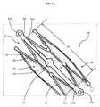
図1に、本発明の一実施形態、すなわち、径方向に圧縮された形態の固定具20と当該固定具に対して長手方向に整列配置されたブリッジ30とを有する圧縮された形態の植込装置10、を図示する。図1の実施形態において、固定具20は、長手方向軸線と管腔21とをもつチューブ形状を有する。固定具20は、固定具の全長にわたり長手方向に間隔をあけて配置された複数の蛇行部材23から構成されている。各蛇行部材23は、複数の峰部と谷部とから構成されており、各峰部は固定具の遠位端側に向かって突出し、各谷部は固定具の近位端側に向かって突出している。各蛇行部材23は、コネクター24で長手方向に隣接する蛇行部材に接続されている。コネクターは、図1には図示されているが、本発明の固定具の必須の要件ではなく、図1の実施形態に特有の要素である。図1において、コネクター24は、第1の蛇行部材の峰部から第2の蛇行部材の谷部まで延びている。コネクター24の長さは、D1の長さを調整するために必要に応じ変更してもよく、図1に示した長さに限定されない。コネクター24は、必要な場合に、固定具を、拡張後に再度圧縮された形態につぶす際の補助となる、図2に示す一ないし複数のピンチポイント28をさらに有するものであってもよい。ステントの峰部および谷部のデザインは、ブリッジがステントに接続するポイント間の距離がステントの拡張時に短くなるものである限りにおいて、当該技術分野において知られているように変えることが可能である。FIG. 1 illustrates an embodiment of the present invention, ie, a compressed form of implant having a radially compressed
囲まれたスペースであるセル25が、蛇行部材およびコネクターの配置によって形成されている。ステント周りの周方向に整列配置されている複数のセル25が壁22、すなわち固定具20の外包、を形成する。図1の圧縮された形態において、固定具20は、拡張された形態のときよりも径が小さい。圧縮された形態における固定具20の長さと径は、同様のステント技術において知られているように、標的となる血管内での拡張のため、必要に応じて、寸法を設定することができる。固定具20としては、任意の固定具、つまり、通常、経皮的心臓血管処置などに用いられる地金ステントや薬剤溶出型ステントを含むステントが採用できる。A
図1に示すように、ブリッジ30が固定具20に取り付けられている。ブリッジ30は、端部31aおよび31b、そして端部31aおよび31bの間に配置されたプレート30を含む。ブリッジの長さは、圧縮された形態において距離D1に及ぶ。図1において、ブリッジ30は、端部31bにおいて第1の蛇行リング23を、端部31aにおいて第2の蛇行リング23に接続する。端部31bは、第1の蛇行リングに接続され、端部31aは第2の蛇行リングに接続されている。 As shown in FIG. 1, a
図1において、セル25は、長手方向軸線に沿った反対側の頂点にあたる位置にポイント26aおよび26bを有する。2つの端部31aおよび31bは、それぞれ、ポイント26aおよび26bに取り付けられている。固定具20の各セルは、サイズおよび形状が不均一である。ブリッジ30は、固定具20の任意のセルに取り付けることができる。さらに、ブリッジ30は、固定具20と同じ材料で作られていてもよく、異なる生体適合材料で作られていてもよい。 In FIG. 1, the
図1において、ポイント26aおよび26bは、それぞれ、さらに、リング27aおよび27bを含んでいてもよい。リング27aおよび27bは、ブリッジ30の固定具20への取り付けを補助する、固定具20の構造的な特徴であり、ブリッジが固定具とは別に製造される場合に、ブリッジを固定具に固定する取付ポイントを提供する。さらに、リング27aおよび27bは、固定具が拡径しブリッジ30が弓状に曲がるときに固定具にかかる力を緩和するはたらきを有していてもよい。リング27aおよび27bは、図1においては円形を有するものとして図示されているが、この形状に限定されない。ブリッジ30を固定具20に取り付けるために、リング27aおよびbに円形でない形状を採用してもよい。さらに、リング27aおよび27bは、同じ形状またはサイズである必要はない。たとえば、リング27aがリング27bよりも大きくてもよいし、その逆であってもよい。ブリッジ30の固定具20への取り付けは、本明細書中において後述するような、溶接、はんだ付け、ろう付けなど、当該技術分野において公知の方法によって行うことができる。 In FIG. 1, points 26a and 26b may further include
図1に、圧縮された形態の固定具20を示す。この状態において、D1はポイント26aおよび26bの間の距離であり、ブリッジ30はD1の範囲を架け渡されている。さらに、ブリッジは、固定具20の管腔内に入り込んではいないので、圧縮されているときの固定具の部材に対し整列して配置されている。ブリッジは、固定具が拡張すると管腔内で弓状に曲がる範囲で所望の長さとすることができる。図1に示す実施形態においては、ブリッジ30は、D1と同じ長さである。他の実施形態において、例えば図3では、ブリッジ30は、湾曲部を含んでおり、長さはD1よりも長くてもよい。ブリッジの幅および厚みは、必要に応じ任意の寸法とすることができる。たとえば、幅および厚みは、図1および図2に示すように、固定具よりも大きくてもよい。代替的に、ブリッジの幅および厚みは、図6に示すように、固定具の部材と実質的に等しくてもよい。 FIG. 1 shows a
図1において、プレート35は、ブリッジ30の中点ないしその近傍に配置されており、ブリッジの隣接する部分よりも幅が広くてもよい。プレート35は、ブリッジ30の任意の位置に配置してよいのであり、必ずしも図1に示すような中央位置である必要はない。プレート35は、センサーおよび追加の接合補助リングを取り付けることができるよう構成されている。プレート35は、センサーの全領域をプレート35がカバーする大きさに設定されている。さらに、プレートの大きさは、ブリッジの他の部分の幅および厚みとは独立に変更することができる。たとえば、図1および図2においては、ブリッジの幅が、図3のブリッジ40に比べると広いので、図1および図2のプレート35は、図3のプレート45の不規則な形状と比較すると、より円に近い形状となっている。プレート35は、センサーに場所を提供するため、任意の形状とすることができる。図示せぬ代替実施形態として、プレートは、開口部を含むものとして、そのセンサー用開口部の内部にセンサーを配置した上で、接合補助リングにより固定することができるようにしてもよい。 In FIG. 1, the
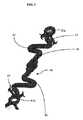
図2に、拡張された形態の、図1の植込装置10を図示する。固定具20は、図1の圧縮された固定具20に比べると、径方向に拡張され、管腔21の径が大きくなっている。この形態において、セル25は、圧縮された形態のときのセル25と比べて、長手方向に短く、周方向に広くなっている。固定具20の全長は、隣接する波形リング間距離が短くならない限りにおいて、短縮する必要はない。すなわち、短縮は、ブリッジが配置されているセルのみに局所化してもよい。 FIG. 2 illustrates the
図2のD2は拡張された形態におけるポイント26aおよび26bの間の距離である。固定部20の拡張は、ポイント26aおよび26bを長手方向軸線に沿って互いに近接移動させるので、図2のD2は図1のD1よりも小さい。デリバリー時には、植込装置は、デリバリーカテーテル内に径方向に拘束されており、ブリッジ30は、壁22と整列して配置されている。固定具の拡張によって、ポイント26aおよび26b間の距離が短くなり、端部31aおよび31bが相互に近接する向きに押圧される。固定具20が拡張されるとき、ブリッジ30は、固定具の圧縮された形態における端部31aおよび31b間の距離と同じ一定の長さを維持するよう構成されている。その結果、ブリッジは、図2に示す弓状に曲がった姿勢をとり、固定具20の管腔内に入り込む。ブリッジが弓状に曲がると、プレート35も管腔21内に入り込む。ブリッジ30の弓状に曲がった姿勢によって、プレート35およびそこに配置された任意のセンサーを血管壁から離間させた状態が保たれる(図2にセンサーは図示していない)。ブリッジは、プレート35を壁22から任意の間隔を置いて離れるように管腔21内に入り込ませるべく構成することができる。一実施形態において、ブリッジは、標的となる血管の中央にプレート35が来るように構成される。他の実施形態において、ブリッジは、弓状部の頂端が壁22から少なくとも2.5mm離間するよう構成されていてもよい。図2において、ブリッジ30は、さらに、溶接ポイント80、すなわちブリッジを固定具に溶接することができる領域、を有する。溶接ポイントは、図2に示す配置に限定されないのであり、ブリッジの任意の場所に配置することができる。 D2 in FIG. 2 is the distance between
ブリッジは、拡張された固定具における所望の弓状部のかたちとなるように、前処理を施してもよい。たとえば、ブリッジが金属製の場合、装置内に組み付けられる前に弓状となるように前処理を施すことができる。前処理方法の非限定的な例としては、スタンピングおよび熱処理が挙げられる。 The bridge may be pretreated to provide the desired arcuate shape in the expanded fixture. For example, if the bridge is made of metal, it can be pretreated so that it is arcuate before being assembled into the device. Non-limiting examples of pretreatment methods include stamping and heat treatment.
図面に示した装置は、一つのブリッジを含むものであるが、植込装置は、同一のセンサー、もしくは、図示しない複数の生理学的パラメーターを測定するため各ブリッジに固定された異なるセンサーを装着した複数のブリッジを一ないし複数のセルに有するものであってもよい。装置が二つ以上のブリッジを含む場合、ブリッジは、互いに独立に弓状に曲がることができるように固定具に配置することができる。 Although the device shown in the drawing includes a single bridge, the implanter may have a plurality of sensors mounted with the same sensor or different sensors fixed to each bridge to measure multiple physiological parameters (not shown). One or a plurality of cells may have a bridge. If the device includes more than one bridge, the bridges can be placed on the fixture so that they can be bent in an arc independently of each other.
図3に、ブリッジ40の他の実施形態を図示する。ブリッジ40は、センサー用取付部位として用いられるプレート45と、一連の湾曲部42,43とを有する。端部41aおよび41bがブリッジ40の両端部に配置されている。ブリッジ40は、プレート45の両側にそれぞれ一対の湾曲部42および43を有する。図示せぬ代替実施形態において、ブリッジのプレート45のどちらか一方の側に設ける湾曲部の数を増やしたり減らしたりしてもよく、プレート45がブリッジにおいて配置される位置も任意の位置でよい。湾曲部は、所望の膨出幅を有するものとすることが可能で、一つのブリッジ内の湾曲部が同じ膨出幅を有する必要はない。図3において、ブリッジ40は、平らに形成されており、すべての部分は同一平面内にあり、湾曲部42および43は、それぞれ、ブリッジ端部41aおよび41bから実質的に垂直な向きに設けられている。プレート45のそれぞれの側の湾曲部は、ブリッジ40の中点に対して対称である。この実施形態では、湾曲部によって、固定具が拡張するときに弓状に曲がった姿勢を形成するのが容易になっている。さらに、湾曲部の数と種類によって、ブリッジの管腔壁からの離間距離を調整することができる。ブリッジは湾曲部が多ければそれにともない柔軟性が生じ、湾曲部がすくないと柔軟性は低下する。 FIG. 3 illustrates another embodiment of the
固定具が拡張されると、ポイント41aおよび41bは互いに近接する方向に押され、セル25の長手方向の延長が短くなり、ブリッジ40が弓状に曲がり、湾曲部(42および43)で曲がる。図1〜2のまっすぐなブリッジの実施形態と同様、ブリッジ40が弓状に曲がった姿勢の時には、プレート45は管腔21内に入り込み、プレート45を壁22から所定距離に維持する。ブリッジ40が弓状に曲がると、湾曲部は、プレート45が管腔内に入り込むように、実質的にまっすぐになるよう構成されている。 When the fixture is expanded, the
図5に、ブリッジと接合補助リングを除外したセンサー60を図示する。センサー60は、ハウジング501と振動部材510とを有する。振動部材510は、当該技術分野において知られているように、温度、圧力、流体流量、その他の生化学特性に関連するデータを収集するよう構成することができる。センサー60は、体外の装置、たとえば、トランスデューサーとの間で応答指令信号を送ったり通信したりすることができるよう構成されている。センサーハウジング501は、センサーの他の構成部品(これも周知であり、前記の引用技術文献に記載されている)を含んでいてもよい。図5に示すように、振動部材510は、ハウジング501の一段高くなった部分であるハウジングセクション502に配置されている。 FIG. 5 illustrates the
低いハウジングセクション504および506が、一段高いハウジングセクション502の両サイドに配置されている。センサー60の寸法は、図5に示されているスケールに限定されない。センサー60の高さ(H)は、一段高いハウジングセクション502の高さと同様に、当該技術分野で知られた方法により必要に応じて変更してもよい。また、ハウジング501の幅および長さは、低いハウジングセクション504および506と同様に、当該技術分野で知られた方法により必要に応じて変更してもよい。センサーは、前記したように、振動部材510が外部環境に露出するようにブリッジの上に配置されるべく適合させてあり、センサーの寸法は、後述するように、接合補助リングによる固定に適合できるようになっている。図5に示すようなセンサーは全体として小さく、たとえば、体積が0.005〜0.3mm3である。
図5のセンサー60は、長方形を含むが、本発明に用いられるセンサーは、たとえば、米国特許第8,162,839号明細書(この文献の内容はここに、引用により補充する)に記載されているような任意の適当な形状を含むものとすることができる。センサー60は、さまざまなデータの測定値、たとえば、血圧、温度、流体流量、糖やミネラルやガスの含有量、ガス圧、その他の化学物質含有量などを含む、物理的測定値や化学的測定値を取得するよう構成させることができる。また、センサーは、米国特許第5,786,439号明細書に記載されているような、たとえば、PEGなどの生体適合ポリマーまたはゲルでコーティングしてもよい。またさらに、植込装置全体(すなわち、固定具、ブリッジ、接合補助リング)に対して同様にコーティングを施してもよい。 5 includes a rectangle, the sensor used in the present invention is described, for example, in US Pat. No. 8,162,839, the contents of which are hereby incorporated by reference. Any suitable shape can be included. The
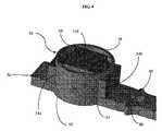
図4に、接合補助リング50によってプレート35に固定されたセンサー60の一実施形態を示す。図4に示す接合補助リングは、外壁51と、上端縁58と、側部開口54aおよび54bと、下端縁56とを有する。ある一部の実施形態では、センサーは、プレート35に直接取り付けるのに適さない材料から構成されている。そのような場合に、センサーを直接プレートに溶接せずにセンサー60をプレート35に固定するのに、接合補助リングを使用することができる。センサー60および接合補助リング50は、プレートの管腔側の(luminal)表面、すなわち固定具の内部管腔に面した側に、取り付けることができる。他の実施形態において、センサー60および接合補助リング50は、プレート35の管腔側でない方の(abluminal)表面、すなわち固定具の血管壁に面した側に、取り付けることができる。図4において、接合補助リング50の断面は円形だが、たとえば、卵形や楕円形など他の形状も、本発明の範囲に含まれる。FIG. 4 illustrates one embodiment of a
図4に示すように、センサー60が接合補助リング50内に嵌合し、接合補助リングがセンサーをプレート35に固定している。図4の実施形態において、側部開口54aおよび54bは、センサーの低いハウジングセクション504および506を突出させることで、センサーをブリッジに固定している。振動部材510は、接合補助リングの内部に収容され露出している。図示せぬ他の実施形態では、センサーは、接合補助リングによって完全に囲まれ、センサーにリングから突出する部分がないようにしてもよい。接合補助リングは、たとえば、接合補助リングをプレートに固定するタブやクリップを下端縁56に設けるなどの機械的手段や、たとえば、接着剤、溶着、ろう付け、はんだ付けといった当該技術分野において公知の手法などの他の手段を含む公知の手段により、プレートに取り付けることができる。接合補助リング50は、ブリッジと同じ生体適合材料や、ポリウレタン、ポリマー、ポリカーボネートなどの材料からなるものとすることができる。これらの材料の非限定的な例としては、PEEK−Optima(登録商標)またはChronoFlex(登録商標)が挙げられる。As shown in FIG. 4, the
図4に示すように、接合補助リングの上端縁58は、完全にまたは部分的に開口しており、植込み後において、振動部材510を外部環境に露出させる。接合補助リングの形状は、他の形状を有するセンサーのため、変形してもよく、そうでなければ、囲まれたセンサー60の他の表面を露出させて正しく機能するようにしなければならない。図4の構成において、植込み前と後の両方で外部物質の奔流が直接当たることから振動部材51を保護するべく、接合補助リング50の上端縁58を、センサー60の高さよりも高くなるようにしてもよい。振動部材510の上面は、接合補助リングがセンサーを不適当な接触から保護するように、接合補助リングの上端縁58内に引っ込んでいる。また、精確な植込みのためにセンサー60の配置と向きを表示する血管造影マーカーをプレートに取り付けてもよい。一実施形態において、血管造影マーカーは、センサーハウジング501の下面とプレート35との間に挿入される。血管造影マーカーは、当該技術分野において周知であり、金、ホウ素、タンタル、プラチナイリジウム、や同様の材料から構成することができる。血管造影マーカーの厚みは、10〜50μmの間とすることができる。一実施形態において、それは25μmである。図4には、ブリッジ30の一部が溶接ポイント80を有していることが示されている。As shown in FIG. 4, the
図6に、固定具610とブリッジ630を示す。固定具610は拡張された形態にあり、ブリッジ630は弓状に曲がった姿勢をとっている。ブリッジ630は、端部631aおよび631bを有し、それぞれリング627aおよび627bにおいて固定具に取り付けられている。図に示すように、リング627aと627bとはサイズが異なる。リングは、望ましい材料の量と、拡張可能な固定具にかかる力の量とによって、サイズを変えてもよい。プレート635は、ブリッジ630の中央に配置されている。図6のブリッジ630の幅は、図1のブリッジ30の幅よりも実質的に小さい。ブリッジの幅は、装置上の望ましい材料の量によって、変えてもよい。プレート635の幅は、ブリッジ630の幅よりも大きい。センサー60は、プレートに直接接触しており、接合補助リング50により固定されている。接合補助リング50は、領域660において、溶接などでプレート635に接合させることができる。図6は、プレート635の管腔側でない方の面を示しており、センサーは、プレート635の管腔側の面に取り付けられている。固定具610は、血管造影マーカーを挿入するための血管造影マーカーサイト650を備えていてもよく、この血管造影マーカーは、任意オプションとして、固定具610上の任意の位置に配置することができる。この実施形態において、マーカーサイト650は、さらに、リング627aに付着している。FIG. 6 shows the
本発明の他の態様は、植込装置を製造する方法に関連する。一般に、植込装置は、生体適合材料からなる平坦なシートまたは平面状のシートから、あるいは、チューブから、ブリッジと固定具とを別々に形成して、それら2部材を接合することによって製造することができる。代替的に、ブリッジと固定具とを単一のユニットとして形成してもよい。Another aspect of the invention relates to a method of manufacturing an implant device. In general, an implantation device is manufactured by forming a bridge and a fixture separately from a flat sheet or a flat sheet made of a biocompatible material, or from a tube, and joining the two members together. Can do. Alternatively, the bridge and fixture may be formed as a single unit.
装置を単一のユニットとして製造する方法において、当該方法は、(a)ブリッジおよび固定具を単一のユニットとして製造すること、(b)ブリッジおよび固定具を熱処理して熱機械的にあらかじめ設定された形状にすること、そして、(c)接合補助リングおよびセンサーをブリッジに組み付けること、を含む。この方法は、さらに、デリバリーカテーテル上に装置をクリンプし固定することを含んでいてもよい。任意追加的に、血管造影マーカーをセンサーに取り付けることもできる。In the method of manufacturing the device as a single unit, the method includes (a) manufacturing the bridge and fixture as a single unit, and (b) heat and mechanically setting the bridge and fixture in advance. And (c) assembling the joining aid ring and sensor to the bridge. The method may further include crimping and securing the device on the delivery catheter. Optionally, an angiographic marker can be attached to the sensor.
ブリッジおよび固定具の単一のユニットとしての製造は、チューブや、平坦なシートまたは平面状のシートを材料としてレーザーエッチングまたは化学エッチングによって行い、この平坦ないし平面状のパターンを丸めて溶接してチューブ状にすることにより実現することができる。 The manufacture of the bridge and fixture as a single unit is carried out by laser etching or chemical etching using a tube, flat sheet or flat sheet as a material, and this flat or flat pattern is rolled and welded to form a tube. This can be realized by forming a shape.
熱処理ステップは、固定具をマンドレル上に固定し、そこで予め成形されたディボット上にブリッジが配置され、拡張された固定具の形態に熱機械的に予め設定された形状を付与してブリッジの中に弓状に曲げるために必要な熱および力を加えることを含んでいる。固定具の望ましい拡張サイズ、たとえば、10mm径,8mm径,6mm径、に応じて、適切なサイズのマンドレルが使用される。好ましくは、固定具は、熱が固定具に均等に加わるようにしっかりと固定される。固定具およびブリッジが、単一のユニットとして形成される場合、マンドレルは、さらに、ブリッジと整列するディボットを有し、ブリッジが熱処理の間そのディボット内で弓状に曲がるようになっている。 The heat treatment step secures the fixture on the mandrel, where the bridge is placed on a pre-formed divot, giving the expanded fixture configuration a thermo-mechanically preset shape to form the inside of the bridge. Includes applying the heat and power necessary to bend into an arc. Depending on the desired expansion size of the fixture, for example, 10 mm diameter, 8 mm diameter, 6 mm diameter, an appropriately sized mandrel is used. Preferably, the fixture is securely fastened so that heat is evenly applied to the fixture. When the fixture and bridge are formed as a single unit, the mandrel further has a divot aligned with the bridge such that the bridge bends in the divot during heat treatment.
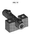
図7A〜Dに、熱処理プロセスのための固定具とブリッジとの固定の一実施形態を示す。図7Aにおいて、単一のユニットとして形成されている固定具20およびブリッジ30がマンドレル810上に配置されている。マンドレル810は、マンドレルの表面の凹みであってその上にブリッジが整列配置されるディボット830を備えている。固定具20の製造プロセス中に、固定具は、マンドレル上に配置されると、固定具をマンドレル上の一ないし複数の配向穴890に整列させる、一ないし複数の配向パネル90を有していてもよい。各パネル90は、マンドレル上の配向穴90の中に嵌入する配向ねじ840で、マンドレルに固定される。配向パネル90と配向穴890と配向ねじ840とを整列配置させることによって、ブリッジ30をディボット830に対して確実に整列配置させることができる。配向パネル90は、任意の形状・サイズでよく、図7A〜7Dに示した実施形態に限定されない。 7A-D illustrate one embodiment of fixing fixtures and bridges for a heat treatment process. In FIG. 7A, a
固定具20がマンドレル810上に固定されると、マンドレルは、図7Bおよび7Cに示すような下側ブロック850のソケット852内に配置される。ソケット852は、マンドレル810を固定するよう構成されている。下側ブロック850は、さらに、2つのブロック穴855および856とスタッド857とを有している。図7Cにおいて、スタッド857は、マンドレル810の対応する穴または凹部820内に嵌入することで、マンドレルが下側ブロック850に対して横方向にずれないようになっている。スタッド857および凹部820の向きも、ディボット830が確実に2つのブロック穴855の間にくるよう保証するものである。 When the
図7Dに、固定具およびブリッジを含む完全に組み立て済みの熱処理ブロックを示す。図7Dにおいて、上側ブロック860が下側ブロック850の上面に配置され、ブロックねじ870で下側ブロック850に固定されている。上側ブロック860は、マンドレル上のディボット830の形状に一致する図示せぬ突起を含んでいる。上側ブロック860が、下側ブロック850上に固定されると、突起がディボット830内に押し込まれ、ブリッジ30が下方向に押しつけられてマンドレルディボット内に押し込まれ、ブリッジ30に弓状に曲がった形状を与える。このステップは、熱機械的に予め設定された形状に熱処理することを伴う。任意追加的に、上側ブロック860を下側ブロック850に固定した後で、配向ねじ840を取り除いてもよい。熱処理に先立って配向ねじ840を取り除くと、熱処理がより効率的になるというメリットがあるかもしれない。配向パネル90は、配向ねじ840を取り除いた後いつでも固定具から取り除くことができる。 FIG. 7D shows a fully assembled heat treatment block including fixtures and bridges. In FIG. 7D, the
熱処理中は、装置を、形状記憶形態にするために、当該技術分野において知られている方法で加熱してもよい。一実施形態において、固定具は、約25〜40分間、600±3℃に加熱してもよい。代替的に、固定具は、約70〜85分間、320±3℃に加熱してもよい。この方法に適した熱処理システムは公知である。熱機械的に予め設定された形状にする熱処理によって、軟らかい状態の固定具およびブリッジ、すなわち、拡張された固定具と弓状に曲げられたブリッジとが形成される。 During the heat treatment, the apparatus may be heated by methods known in the art to bring it into shape memory form. In one embodiment, the fixture may be heated to 600 ± 3 ° C. for about 25-40 minutes. Alternatively, the fixture may be heated to 320 ± 3 ° C. for about 70-85 minutes. Heat treatment systems suitable for this method are known. A heat-mechanically pre-set heat treatment forms soft fixtures and bridges, ie, expanded fixtures and arcuately bent bridges.
熱処理が完了すると、センサーおよび接合補助リングがブリッジ上に組み付けられる。熱処理された固定具は、凹みを有する治具にセットされ、その凹みの中に、接合補助リング、センサーおよび/または血管造影マーカーが配置される。ブリッジが治具の凹みにきちんと整列されて配置されると、接合補助リングは、公知の方法、たとえば、溶接で、プレートに固定される。その後、固定具は、接合補助リング、センサーおよび/またはマーカーと共に、デリバリー装置に組み付けるため、治具から取り外されてもよい。 When the heat treatment is complete, the sensor and joining aid ring are assembled on the bridge. The heat-treated fixture is set in a jig having a recess, and a joining auxiliary ring, a sensor, and / or an angiographic marker are disposed in the recess. When the bridge is placed in proper alignment with the recess of the jig, the joining auxiliary ring is fixed to the plate by a known method, for example, welding. The fixture may then be removed from the jig for assembly with the delivery aid ring, sensor and / or marker to the delivery device.
図8に、接合補助リングおよびセンサーをブリッジに取り付けるプロセスの一実施形態を示す。ブリッジ30が一緒になった熱処理後の固定具20が、凹み領域910を有する円柱状の治具901にセットされる。接合補助リングが、上端縁58を治具の中央に向けて、凹み領域910の中に配置される。そして、センサー60が、振動部材510を下向きにして、接合補助リング50の中に配置される。オプションとしての血管造影マーカー95を、治具の内部に配置してもよい。接合補助リング、センサー、オプションの血管造影マーカーの凹み領域910への配置は、固定具20を治具にセットする前に行っても後に行ってもよい。固定具20は、プレート35が凹んだ領域910の接合補助リング50と整列するように、配置される。その後、接合補助リング50が、公知の手段、たとえば、接合補助リングをプレートに溶接することにより、プレート35に固定され、装置の組み立てを完成させることができる。 FIG. 8 illustrates one embodiment of a process for attaching a joining aid ring and sensor to the bridge. The
組み立て後の装置は、公知の従来型の手段によりクリンプされ、デリバリー装置に固定されてもよい。そのようなデリバリー装置としては、デリバリーカテーテルがある。既存のクリンプ装置およびクリンプされた固定具を固定する方法は、当該技術分野において周知であり、たとえば、米国特許第6,387,118号、第6,108,886号、第6,092,273号、第6,082,990号、第6,074,381号,第6,06,310号、第5,99,200号、7,225,518号の各明細書に記載されている(これらの文献の内容はここに、引用により補充する)。 The assembled device may be crimped by known conventional means and secured to the delivery device. An example of such a delivery device is a delivery catheter. Existing crimping devices and methods of securing crimped fasteners are well known in the art, for example, U.S. Pat. Nos. 6,387,118, 6,108,886, 6,092,273. No. 6,082,990, No. 6,074,381, No. 6,06,310, No. 5,99,200, No. 7,225,518 ( The contents of these documents are supplemented here by reference).
本発明の他の実施形態において、装置は、別体の固定具およびブリッジ構成部品から製造することができる。その方法は、拡張可能な固定具と、ブリッジと、センサーとを有し、それによって、拡張可能な固定具が、圧縮および拡張される形態を有し、前記ブリッジが、当該固定具が圧縮された形態のときは固定具の諸部材に整列され、前記固定具が拡張された形態のときは前記管腔内に入り込むよう構成された植込装置の製造に関し、(a)固定具を製造するステップと、(b)ブリッジを製造するステップと、(c)ブリッジを固定具に取り付けるステップと、(d)固定具およびブリッジを熱処理して熱機械的に予め設定された形状にするステップと、(e)センサーをブリッジに組み付けるステップとを有する。この方法は、さらに、デリバリーカテーテル上に装置をクリンプし固定することを含んでいてもよい。任意追加的に、血管造影マーカーをセンサーに取り付けることもできる。ステップ(d)は、ステップ(c)よりも前に実行してもよい。また、ステップ(e)は、ステップ(d)よりも前に実行してもよい。In other embodiments of the present invention, the device can be manufactured from separate fasteners and bridge components. The method includes an expandable fixture, a bridge, and a sensor, whereby the expandable fixture has a configuration that is compressed and expanded, the bridge being compressed by the fixture. In the form of an implant, the device is aligned with the members of the fixture, and when the fixture is in the expanded configuration, the device is configured to enter the lumen, and (a) the fixture is manufactured. (B) manufacturing the bridge; (c) attaching the bridge to the fixture; (d) heat treating the fixture and bridge to a thermomechanically preset shape; (E) attaching the sensor to the bridge. The method may further include crimping and securing the device on the delivery catheter. Optionally, an angiographic marker can be attached to the sensor. Step (d) may be executed before step (c). Further, step (e) may be executed before step (d).
固定具の製造は、チューブを材料としたレーザーエッチングまたは化学エッチングによって、あるいは平坦なシートまたは平面状のシートを材料としたレーザーエッチングまたは化学エッチング後に丸めてチューブ状にすることによって実現することができるが、これらは当該技術分野において公知のステント製造手順である。ブリッジは、同様に、生体適合材料からレーザーエッチングまたは化学エッチングによって製造することができる。 The manufacture of the fixing device can be realized by laser etching or chemical etching using a tube as a material, or by rounding into a tube after laser etching or chemical etching using a flat sheet or a flat sheet as a material. However, these are known stent manufacturing procedures in the art. The bridge can likewise be manufactured from a biocompatible material by laser etching or chemical etching.
固定具およびブリッジを別々に形成することによって、ブリッジを固定具とは異なる熱処理にかけることができるので、固定具とは異なる熱機械的特性を持たせることができる。熱処理ステップは、マンドレルに固定具を配置し固定して、固定具に形状記憶を付与するのに必要な熱を与えることによって行うことができる。固定具は、当該技術分野における公知の方法によってマンドレルに固定することができる。マンドレルのサイズは、固定具の望ましいサイズに応じて、たとえば、10cm、8cm、6mmから選択してもよい。好ましくは、固定具は、熱が固定具に均等に与えられるようマンドレルにしっかりと固定されている。 By forming the fixture and the bridge separately, the bridge can be subjected to a different heat treatment than the fixture and thus can have different thermomechanical properties than the fixture. The heat treatment step can be performed by placing and fixing a fixture on the mandrel and applying heat necessary to impart shape memory to the fixture. The fixture can be secured to the mandrel by methods known in the art. The mandrel size may be selected from, for example, 10 cm, 8 cm, and 6 mm depending on the desired size of the fixture. Preferably, the fixture is firmly secured to the mandrel so that heat is evenly applied to the fixture.
熱処理中は、固定具を、形状記憶形態にするために、当該技術分野において知られている方法で加熱してもよい。一実施形態において、固定具は、約25〜40分間、600±3℃に加熱してもよい。代替的に、固定具は、約70〜85分間、320±3℃に加熱してもよい。この方法に適した熱処理システムは公知である。熱機械的に予め設定された形状にする熱処理によって、軟らかい状態の固定具およびブリッジ、すなわち、拡張された固定具と弓状に曲げられたブリッジとが形成される。 During the heat treatment, the fixture may be heated by methods known in the art to obtain a shape memory configuration. In one embodiment, the fixture may be heated to 600 ± 3 ° C. for about 25-40 minutes. Alternatively, the fixture may be heated to 320 ± 3 ° C. for about 70-85 minutes. Heat treatment systems suitable for this method are known. A heat-mechanically pre-set heat treatment forms soft fixtures and bridges, ie, expanded fixtures and arcuately bent bridges.
熱処理が完了した後で、固定具と、ブリッジと、センサーと、接合補助リングとが組み立てられる。図8の治具901は、固定具、ブリッジ、センサー、接合補助リングの組立体に使用してもよい。まず、接合補助リングを、上端縁58を下向きに治具の中に入れるようにして、凹んだ領域910の中に配置する。そして、センサーを、振動部材510を下向きにして接合補助リング50の中に入りこませるように、配置する。オプションとしての血管造影マーカー95を治具内に配置してもよい。最後に、ブリッジを凹んだ領域910内に配置し、プレートを接合補助リングと整列配置させる。 After the heat treatment is complete, the fixture, bridge, sensor, and joining aid ring are assembled. The jig 901 in FIG. 8 may be used for an assembly of a fixture, a bridge, a sensor, and a joining auxiliary ring. First, the joining auxiliary ring is disposed in the recessed
代替的に、ブリッジ、接合補助リング、センサーおよび/または血管造影マークは、治具901内に配置する前に任意の公知の手段によってあらかじめ組み立てておいてもよい。このあらかじめ組み立てた組立体において、センサーは、オプションの血管造影マーカーをセンサーとブリッジの間に配置して、接合補助リングによってブリッジに固定してもよい。あらかじめ組み付けたブリッジおよびセンサーは、単一部品として、凹んだ領域910の中に配置することができる。その後、固定具20は、ブリッジ30に整列配置されて、ブリッジ30は、たとえば溶接で、固定具に固定することができる。 Alternatively, the bridge, joining aid ring, sensor and / or angiographic mark may be preassembled by any known means prior to placement in the jig 901. In this pre-assembled assembly, the sensor may be secured to the bridge with a joining aid ring with an optional angiographic marker placed between the sensor and the bridge. The pre-assembled bridge and sensor can be placed in the recessed
前記した主題において、本発明の範囲および趣旨を逸脱することなく、さまざまな変更が可能であり、前記明細書に含まれる、あるいは、添付の特許請求の範囲に定義されている主題は、本発明の説明および例示として解釈されることが意図されている。前記教示に照らして、本発明の多くの変更やバリエーションが可能である。 Various changes may be made in the subject matter described above without departing from the scope and spirit of the invention, and the subject matter included in the specification or defined in the appended claims is intended to be It is intended to be construed as a description and illustration. Many modifications and variations of the present invention are possible in light of the above teachings.
Claims (68)
Translated fromJapanese前記固定具に取り付けられた第1の端部と前記固定具に取り付けられた第2の端部とを有し、前記固定具が圧縮された形態にあるときは前記固定具の前記長手方向軸線に実質的に整列配置され、前記固定具が拡張された形態にあるときは前記管腔内に入り込むブリッジと
を有する植込装置。A fixture having a plurality of serpentine rings defining a lumen along a longitudinal axis and having a compressed and expanded configuration;
Having a first end attached to the fixture and a second end attached to the fixture, the longitudinal axis of the fixture when the fixture is in a compressed configuration And a bridge that enters the lumen when the fixture is in an expanded configuration.
(a)前記固定具およびブリッジを単一のユニットとして製造するステップと、
(b)所望の拡張後の前記固定具の直径とディボットとを有するマンドレルに前記した固定具およびブリッジを組み付けるステップと、
(c)前記ディボットの上に前記ブリッジを配置するステップと、
(d)前記固定具および前記ブリッジを熱機械的にあらかじめ設定された形状に熱処理するステップと、
(e)センサーを前記ブリッジに組み付けるステップと
を含む方法。A method for manufacturing the implantable device of claim 1, comprising:
(A) manufacturing the fixture and bridge as a single unit;
(B) assembling the fixture and bridge as described above to a mandrel having the desired expanded diameter and divot of the fixture;
(C) placing the bridge on the divot;
(D) heat-treating the fixture and the bridge into a thermomechanically preset shape;
(E) assembling a sensor to the bridge.
(a)前記固定具を製造するステップと、
(b)前記ブリッジを製造するステップと、
(c)前記固定具および前記ブリッジを熱処理するステップと、
(d)前記ブリッジを前記固定具に取り付けるステップと、
(e)センサーを前記ブリッジに組み付けるステップと
を含む方法。A method for manufacturing the implantable device of claim 1, comprising:
(A) manufacturing the fixture;
(B) manufacturing the bridge;
(C) heat treating the fixture and the bridge;
(D) attaching the bridge to the fixture;
(E) assembling a sensor to the bridge.
(b)前記デリバリーカテーテル上に装着される請求項1の植込装置と
を有する、センサーを植込むためのシステム。(A) a delivery catheter;
A system for implanting a sensor, comprising: (b) the implanting device of claim 1 mounted on the delivery catheter.
前記固定具に取り付けられた第1の端部と前記固定具に取り付けられた第2の端部とを有し、前記固定具が圧縮された形態にあるときは前記固定具の前記長手方向軸線に実質的に整列配置され、前記固定具が拡張された形態にあるときは前記管腔内に入り込むブリッジであって、一対の湾曲部を含むブリッジと
を有する植込装置。A fixture having a plurality of serpentine rings defining a lumen along a longitudinal axis and having a compressed and expanded configuration;
Having a first end attached to the fixture and a second end attached to the fixture, the longitudinal axis of the fixture when the fixture is in a compressed configuration And a bridge that includes a pair of curved portions, the bridge being inserted into the lumen when the fixture is in an expanded configuration.
Applications Claiming Priority (3)
| Application Number | Priority Date | Filing Date | Title |
|---|---|---|---|
| US201361791126P | 2013-03-15 | 2013-03-15 | |
| US61/791,126 | 2013-03-15 | ||
| PCT/IB2014/001565WO2014177936A2 (en) | 2013-03-15 | 2014-03-14 | Implantable device with bridge |
Publications (2)
| Publication Number | Publication Date |
|---|---|
| JP2016517292A JP2016517292A (en) | 2016-06-16 |
| JP6497561B2true JP6497561B2 (en) | 2019-04-10 |
Family
ID=51530524
Family Applications (1)
| Application Number | Title | Priority Date | Filing Date |
|---|---|---|---|
| JP2015562420AActiveJP6497561B2 (en) | 2013-03-15 | 2014-03-14 | Implanting device with bridge |
Country Status (10)
| Country | Link |
|---|---|
| US (2) | US10238339B2 (en) |
| EP (1) | EP2967352B1 (en) |
| JP (1) | JP6497561B2 (en) |
| CN (2) | CN105142502B (en) |
| AU (2) | AU2014261118B2 (en) |
| CA (1) | CA2907036A1 (en) |
| ES (1) | ES2813775T3 (en) |
| IL (1) | IL240991B (en) |
| RU (1) | RU2637417C2 (en) |
| WO (1) | WO2014177936A2 (en) |
Families Citing this family (13)
| Publication number | Priority date | Publication date | Assignee | Title |
|---|---|---|---|---|
| US8128677B2 (en) | 2007-12-12 | 2012-03-06 | Intact Vascular LLC | Device and method for tacking plaque to a blood vessel wall |
| WO2011120050A1 (en)* | 2010-03-26 | 2011-09-29 | Thubrikar Aortic Valve, Inc. | Valve component, frame component and prosthetic valve device including the same for implantation in a body lumen |
| US10667931B2 (en)* | 2014-07-20 | 2020-06-02 | Restore Medical Ltd. | Pulmonary artery implant apparatus and methods of use thereof |
| US9375336B1 (en) | 2015-01-29 | 2016-06-28 | Intact Vascular, Inc. | Delivery device and method of delivery |
| US9433520B2 (en) | 2015-01-29 | 2016-09-06 | Intact Vascular, Inc. | Delivery device and method of delivery |
| US10993824B2 (en) | 2016-01-01 | 2021-05-04 | Intact Vascular, Inc. | Delivery device and method of delivery |
| GB201616092D0 (en) | 2016-09-21 | 2016-11-02 | Imp Innovations Ltd | Apparatus for securing a device in a vascular lumen |
| CN108567511B (en)* | 2017-03-13 | 2020-06-16 | 上海微创医疗器械(集团)有限公司 | Stent system |
| US11660218B2 (en) | 2017-07-26 | 2023-05-30 | Intact Vascular, Inc. | Delivery device and method of delivery |
| US10588644B2 (en)* | 2017-08-31 | 2020-03-17 | DePuy Synthes Products, Inc. | Guide attachment for power tools |
| WO2021186009A1 (en)* | 2020-03-18 | 2021-09-23 | Scandinavian Real Heart Ab | Pressure sensor arrangement and method |
| EP4125739A1 (en)* | 2020-03-24 | 2023-02-08 | The Foundry, LLC | Expandable devices |
| WO2021195664A1 (en)* | 2020-03-24 | 2021-09-30 | The Foundry, Llc | Expandable devices and associated systems and methods |
Family Cites Families (47)
| Publication number | Priority date | Publication date | Assignee | Title |
|---|---|---|---|---|
| US599200A (en) | 1898-02-15 | Robert smallwood | ||
| US606310A (en) | 1898-06-28 | Device for heating water by steam | ||
| US5629008A (en) | 1992-06-02 | 1997-05-13 | C.R. Bard, Inc. | Method and device for long-term delivery of drugs |
| IL108470A (en) | 1994-01-28 | 1998-12-06 | Mizur Technology Ltd | Passive sensor system using ultrasonic energy |
| US5989190A (en) | 1994-01-27 | 1999-11-23 | Mizur Technology, Ltd. | Passive sensor system using ultrasonic energy |
| US5591197A (en)* | 1995-03-14 | 1997-01-07 | Advanced Cardiovascular Systems, Inc. | Expandable stent forming projecting barbs and method for deploying |
| US5786439A (en) | 1996-10-24 | 1998-07-28 | Minimed Inc. | Hydrophilic, swellable coatings for biosensors |
| US6602281B1 (en) | 1995-06-05 | 2003-08-05 | Avantec Vascular Corporation | Radially expansible vessel scaffold having beams and expansion joints |
| US5593442A (en) | 1995-06-05 | 1997-01-14 | Localmed, Inc. | Radially expansible and articulated vessel scaffold |
| RU2108765C1 (en) | 1996-02-26 | 1998-04-20 | Александр Павлович Коршок | Device to be implanted in vessels and hollow organs |
| US5755781A (en)* | 1996-08-06 | 1998-05-26 | Iowa-India Investments Company Limited | Embodiments of multiple interconnected stents |
| US5972016A (en) | 1997-04-22 | 1999-10-26 | Advanced Cardiovascular Systems, Inc. | Stent crimping device and method of use |
| US5992000A (en) | 1997-10-16 | 1999-11-30 | Scimed Life Systems, Inc. | Stent crimper |
| DE19746882A1 (en)* | 1997-10-23 | 1999-04-29 | Angiomed Ag | Expandable stent for tubular anatomical structures such as bile-ducts |
| US6331163B1 (en) | 1998-01-08 | 2001-12-18 | Microsense Cardiovascular Systems (1196) Ltd. | Protective coating for bodily sensor |
| US6082990A (en) | 1998-02-17 | 2000-07-04 | Advanced Cardiovascular Systems, Inc. | Stent crimping tool |
| US5984947A (en)* | 1998-05-04 | 1999-11-16 | Scimed Life Systems, Inc. | Removable thrombus filter |
| US5974652A (en) | 1998-05-05 | 1999-11-02 | Advanced Cardiovascular Systems, Inc. | Method and apparatus for uniformly crimping a stent onto a catheter |
| US6092273A (en) | 1998-07-28 | 2000-07-25 | Advanced Cardiovascular Systems, Inc. | Method and apparatus for a stent crimping device |
| US6074381A (en) | 1998-10-22 | 2000-06-13 | Isostent, Inc. | Cylindrical roller stent crimper apparatus with radiation shield |
| US6660021B1 (en)* | 1999-12-23 | 2003-12-09 | Advanced Cardiovascular Systems, Inc. | Intravascular device and system |
| US6387118B1 (en) | 2000-04-20 | 2002-05-14 | Scimed Life Systems, Inc. | Non-crimped stent delivery system |
| US6442413B1 (en)* | 2000-05-15 | 2002-08-27 | James H. Silver | Implantable sensor |
| WO2001097687A1 (en)* | 2000-06-20 | 2001-12-27 | Chf Solutions, Inc. | Instrumented stent |
| US6764446B2 (en) | 2000-10-16 | 2004-07-20 | Remon Medical Technologies Ltd | Implantable pressure sensors and methods for making and using them |
| WO2002102280A2 (en)* | 2001-06-18 | 2002-12-27 | Rex Medical, L.P. | Removable vein filter |
| US6770032B2 (en) | 2001-12-03 | 2004-08-03 | Microsense Cardiovascular Systems 1996 | Passive ultrasonic sensors, methods and systems for their use |
| US7134341B2 (en) | 2003-04-28 | 2006-11-14 | Zuli Holdings Ltd | Methods and devices for determining the resonance frequency of passive mechanical resonators |
| US9155639B2 (en) | 2009-04-22 | 2015-10-13 | Medinol Ltd. | Helical hybrid stent |
| US8162839B2 (en) | 2003-08-27 | 2012-04-24 | Microtech Medical Technologies Ltd. | Protected passive resonating sensors |
| US7415883B2 (en) | 2004-06-28 | 2008-08-26 | Zuli Holdings Ltd | Method for protecting resonating sensors and open protected resonating sensors |
| WO2005067817A1 (en)* | 2004-01-13 | 2005-07-28 | Remon Medical Technologies Ltd | Devices for fixing a sensor in a body lumen |
| US7225518B2 (en) | 2004-02-23 | 2007-06-05 | Boston Scientific Scimed, Inc. | Apparatus for crimping a stent assembly |
| EP1776066B1 (en)* | 2004-07-02 | 2012-02-08 | Cook Medical Technologies LLC | Stent having arcuate struts |
| US7931659B2 (en)* | 2004-09-10 | 2011-04-26 | Penumbra, Inc. | System and method for treating ischemic stroke |
| US20060122522A1 (en)* | 2004-12-03 | 2006-06-08 | Abhi Chavan | Devices and methods for positioning and anchoring implantable sensor devices |
| US10390714B2 (en)* | 2005-01-12 | 2019-08-27 | Remon Medical Technologies, Ltd. | Devices for fixing a sensor in a lumen |
| EP1948007A1 (en) | 2005-11-15 | 2008-07-30 | Remon Medical Technologies Ltd. | Implant device for fixing a sensor in a body lumen |
| US20070191904A1 (en)* | 2006-02-14 | 2007-08-16 | Imad Libbus | Expandable stimulation electrode with integrated pressure sensor and methods related thereto |
| EP2046242A4 (en)* | 2006-07-07 | 2010-08-25 | Endotronix Inc | Methods and systems for monitoring an endoprosthetic implant |
| JP5156749B2 (en)* | 2006-09-15 | 2013-03-06 | カーディアック ペースメイカーズ, インコーポレイテッド | Implantable sensor anchor |
| EP2166984B1 (en)* | 2007-06-22 | 2016-08-31 | C.R. Bard, Inc. | Flexible stent with hinged connectors |
| MX2012005150A (en)* | 2009-11-03 | 2012-08-17 | Large Bore Closure L L C | Closure device. |
| US8475372B2 (en)* | 2010-10-29 | 2013-07-02 | Medtronic Vascular, Inc. | Implantable medical sensor and fixation system |
| US8727996B2 (en)* | 2011-04-20 | 2014-05-20 | Medtronic Vascular, Inc. | Delivery system for implantable medical device |
| CA3060248C (en) | 2011-09-01 | 2022-04-12 | Microtech Medical Technologies Ltd. | Method of detecting portal and/or hepatic pressure and a portal hypertension monitoring system |
| EP2816969B1 (en)* | 2012-02-23 | 2018-06-13 | Merit Medical Systems, Inc. | Vascular filter |
- 2014
- 2014-03-14CNCN201480015014.9Apatent/CN105142502B/enactiveActive
- 2014-03-14ESES14767093Tpatent/ES2813775T3/enactiveActive
- 2014-03-14EPEP14767093.9Apatent/EP2967352B1/enactiveActive
- 2014-03-14AUAU2014261118Apatent/AU2014261118B2/ennot_activeCeased
- 2014-03-14CNCN201711328720.0Apatent/CN107960999B/enactiveActive
- 2014-03-14RURU2015135238Apatent/RU2637417C2/ennot_activeIP Right Cessation
- 2014-03-14WOPCT/IB2014/001565patent/WO2014177936A2/enactiveApplication Filing
- 2014-03-14USUS14/211,397patent/US10238339B2/enactiveActive
- 2014-03-14CACA2907036Apatent/CA2907036A1/ennot_activeAbandoned
- 2014-03-14JPJP2015562420Apatent/JP6497561B2/enactiveActive
- 2015
- 2015-09-01ILIL240991Apatent/IL240991B/enactiveIP Right Grant
- 2017
- 2017-03-17AUAU2017201834Apatent/AU2017201834B2/ennot_activeCeased
- 2019
- 2019-02-20USUS16/280,418patent/US11160506B2/enactiveActive
Also Published As
| Publication number | Publication date |
|---|---|
| EP2967352A2 (en) | 2016-01-20 |
| HK1212578A1 (en) | 2016-06-17 |
| AU2017201834A1 (en) | 2017-04-06 |
| ES2813775T3 (en) | 2021-03-24 |
| US20140276141A1 (en) | 2014-09-18 |
| AU2017201834B2 (en) | 2018-06-21 |
| US11160506B2 (en) | 2021-11-02 |
| WO2014177936A2 (en) | 2014-11-06 |
| RU2637417C2 (en) | 2017-12-04 |
| CN107960999A (en) | 2018-04-27 |
| CA2907036A1 (en) | 2014-11-06 |
| IL240991A0 (en) | 2015-11-30 |
| US20190175105A1 (en) | 2019-06-13 |
| CN107960999B (en) | 2020-11-17 |
| AU2014261118B2 (en) | 2017-04-13 |
| IL240991B (en) | 2019-12-31 |
| CN105142502A (en) | 2015-12-09 |
| RU2015135238A (en) | 2017-04-21 |
| CN105142502B (en) | 2018-01-16 |
| US10238339B2 (en) | 2019-03-26 |
| AU2014261118A1 (en) | 2015-09-03 |
| WO2014177936A3 (en) | 2015-03-05 |
| JP2016517292A (en) | 2016-06-16 |
| EP2967352B1 (en) | 2020-06-24 |
Similar Documents
| Publication | Publication Date | Title |
|---|---|---|
| JP6497561B2 (en) | Implanting device with bridge | |
| US7572228B2 (en) | Devices for fixing a sensor in a lumen | |
| US5354309A (en) | Apparatus for widening a stenosis in a body cavity | |
| KR101019896B1 (en) | Flexible and consistent stents and methods of making the same | |
| JP5067891B2 (en) | Implantable device for securing a sensor to a body lumen | |
| US7637935B2 (en) | Endoprosthesis for controlled contraction and expansion | |
| US20090125096A1 (en) | Stent Graft With Pins | |
| WO2007106533A1 (en) | Sensor, delivery system, and method of fixation | |
| US20040044393A1 (en) | Implant system | |
| US20070219610A1 (en) | Stent with flap | |
| JP2009515589A (en) | Stent with helical side branch support design | |
| CA2223479A1 (en) | Endovascular stent | |
| EP1811926A2 (en) | Endoprosthesis having foot extensions | |
| WO2001097687A1 (en) | Instrumented stent | |
| HK1212578B (en) | Implantable device with bridge and methods of manufacturing thereof | |
| JP2009508592A (en) | Split type device for inlet protection | |
| CA2079944A1 (en) | Apparatus for widening a stenosis in a body cavity | |
| US20120109275A1 (en) | Stent with radially asymmetric force distribution |
Legal Events
| Date | Code | Title | Description |
|---|---|---|---|
| A621 | Written request for application examination | Free format text:JAPANESE INTERMEDIATE CODE: A621 Effective date:20170309 | |
| A977 | Report on retrieval | Free format text:JAPANESE INTERMEDIATE CODE: A971007 Effective date:20171227 | |
| A131 | Notification of reasons for refusal | Free format text:JAPANESE INTERMEDIATE CODE: A131 Effective date:20180206 | |
| A521 | Request for written amendment filed | Free format text:JAPANESE INTERMEDIATE CODE: A523 Effective date:20180516 | |
| A601 | Written request for extension of time | Free format text:JAPANESE INTERMEDIATE CODE: A601 Effective date:20180507 | |
| A521 | Request for written amendment filed | Free format text:JAPANESE INTERMEDIATE CODE: A523 Effective date:20180725 | |
| A131 | Notification of reasons for refusal | Free format text:JAPANESE INTERMEDIATE CODE: A131 Effective date:20181023 | |
| A521 | Request for written amendment filed | Free format text:JAPANESE INTERMEDIATE CODE: A523 Effective date:20190118 | |
| TRDD | Decision of grant or rejection written | ||
| A01 | Written decision to grant a patent or to grant a registration (utility model) | Free format text:JAPANESE INTERMEDIATE CODE: A01 Effective date:20190205 | |
| A61 | First payment of annual fees (during grant procedure) | Free format text:JAPANESE INTERMEDIATE CODE: A61 Effective date:20190227 | |
| R150 | Certificate of patent or registration of utility model | Ref document number:6497561 Country of ref document:JP Free format text:JAPANESE INTERMEDIATE CODE: R150 | |
| R250 | Receipt of annual fees | Free format text:JAPANESE INTERMEDIATE CODE: R250 | |
| R250 | Receipt of annual fees | Free format text:JAPANESE INTERMEDIATE CODE: R250 | |
| R250 | Receipt of annual fees | Free format text:JAPANESE INTERMEDIATE CODE: R250 | |
| R250 | Receipt of annual fees | Free format text:JAPANESE INTERMEDIATE CODE: R250 |