JP6497447B2 - Luneberg lens antenna device - Google Patents
Luneberg lens antenna deviceDownload PDFInfo
- Publication number
- JP6497447B2 JP6497447B2JP2017552338AJP2017552338AJP6497447B2JP 6497447 B2JP6497447 B2JP 6497447B2JP 2017552338 AJP2017552338 AJP 2017552338AJP 2017552338 AJP2017552338 AJP 2017552338AJP 6497447 B2JP6497447 B2JP 6497447B2
- Authority
- JP
- Japan
- Prior art keywords
- antenna
- luneberg lens
- patch
- array
- antennas
- Prior art date
- Legal status (The legal status is an assumption and is not a legal conclusion. Google has not performed a legal analysis and makes no representation as to the accuracy of the status listed.)
- Active
Links
Images


Classifications
- H—ELECTRICITY
- H01—ELECTRIC ELEMENTS
- H01Q—ANTENNAS, i.e. RADIO AERIALS
- H01Q15/00—Devices for reflection, refraction, diffraction or polarisation of waves radiated from an antenna, e.g. quasi-optical devices
- H01Q15/02—Refracting or diffracting devices, e.g. lens, prism
- H01Q15/08—Refracting or diffracting devices, e.g. lens, prism formed of solid dielectric material
- H—ELECTRICITY
- H01—ELECTRIC ELEMENTS
- H01Q—ANTENNAS, i.e. RADIO AERIALS
- H01Q1/00—Details of, or arrangements associated with, antennas
- H01Q1/27—Adaptation for use in or on movable bodies
- H01Q1/32—Adaptation for use in or on road or rail vehicles
- H01Q1/3208—Adaptation for use in or on road or rail vehicles characterised by the application wherein the antenna is used
- H01Q1/3233—Adaptation for use in or on road or rail vehicles characterised by the application wherein the antenna is used particular used as part of a sensor or in a security system, e.g. for automotive radar, navigation systems
- H—ELECTRICITY
- H01—ELECTRIC ELEMENTS
- H01Q—ANTENNAS, i.e. RADIO AERIALS
- H01Q19/00—Combinations of primary active antenna elements and units with secondary devices, e.g. with quasi-optical devices, for giving the antenna a desired directional characteristic
- H01Q19/06—Combinations of primary active antenna elements and units with secondary devices, e.g. with quasi-optical devices, for giving the antenna a desired directional characteristic using refracting or diffracting devices, e.g. lens
- H01Q19/062—Combinations of primary active antenna elements and units with secondary devices, e.g. with quasi-optical devices, for giving the antenna a desired directional characteristic using refracting or diffracting devices, e.g. lens for focusing
- H—ELECTRICITY
- H01—ELECTRIC ELEMENTS
- H01Q—ANTENNAS, i.e. RADIO AERIALS
- H01Q21/00—Antenna arrays or systems
- H01Q21/0006—Particular feeding systems
- H01Q21/0025—Modular arrays
- H—ELECTRICITY
- H01—ELECTRIC ELEMENTS
- H01Q—ANTENNAS, i.e. RADIO AERIALS
- H01Q21/00—Antenna arrays or systems
- H01Q21/06—Arrays of individually energised antenna units similarly polarised and spaced apart
- H01Q21/061—Two dimensional planar arrays
- H01Q21/064—Two dimensional planar arrays using horn or slot aerials
- H—ELECTRICITY
- H01—ELECTRIC ELEMENTS
- H01Q—ANTENNAS, i.e. RADIO AERIALS
- H01Q21/00—Antenna arrays or systems
- H01Q21/06—Arrays of individually energised antenna units similarly polarised and spaced apart
- H01Q21/061—Two dimensional planar arrays
- H01Q21/065—Patch antenna array
- H—ELECTRICITY
- H01—ELECTRIC ELEMENTS
- H01Q—ANTENNAS, i.e. RADIO AERIALS
- H01Q21/00—Antenna arrays or systems
- H01Q21/06—Arrays of individually energised antenna units similarly polarised and spaced apart
- H01Q21/08—Arrays of individually energised antenna units similarly polarised and spaced apart the units being spaced along or adjacent to a rectilinear path
- H—ELECTRICITY
- H01—ELECTRIC ELEMENTS
- H01Q—ANTENNAS, i.e. RADIO AERIALS
- H01Q21/00—Antenna arrays or systems
- H01Q21/28—Combinations of substantially independent non-interacting antenna units or systems
Landscapes
- Engineering & Computer Science (AREA)
- Computer Security & Cryptography (AREA)
- Radar, Positioning & Navigation (AREA)
- Remote Sensing (AREA)
- Aerials With Secondary Devices (AREA)
- Variable-Direction Aerials And Aerial Arrays (AREA)
Description
Translated fromJapanese本発明は、ルネベルグレンズを備えたルネベルグレンズアンテナ装置に関する。 The present invention relates to a Luneberg lens antenna apparatus including a Luneberg lens.
ルネベルグレンズを用いて、複数の衛星からの電波を受信可能なアンテナ装置が知られている(例えば、特許文献1参照)。特許文献1に記載されたアンテナ装置では、ルネベルグレンズの焦点位置にマイクロ波の送受信機が設けられている。このアンテナ装置では、送受信機の位置を移動させることによって、電波の受信方向を変化させて、標的とする衛星からの電波を受信している。 An antenna device that can receive radio waves from a plurality of satellites using a Luneberg lens is known (see, for example, Patent Document 1). In the antenna device described in
ところで、特許文献1に記載されたアンテナ装置では、例えばMIMO(multiple-input and multiple-output)への適用を考慮していない。このため、広角な走査とマルチビームを形成するための条件については検討されていない。これに加えて、球形状のルネベルグレンズに表面に設けた複数の送受信機からケーブルによって信号を取り出す必要があり、ルネベルグレンズとは別個にケーブルを支持する部材等が必要になるという問題もある。 Incidentally, the antenna device described in
本発明は上述した従来技術の問題に鑑みなされたもので、本発明の目的は、広角な走査とマルチビームの形成が可能なルネベルグレンズアンテナ装置を提供することにある。 The present invention has been made in view of the above-described problems of the prior art, and an object of the present invention is to provide a Luneberg lens antenna apparatus capable of wide-angle scanning and multi-beam formation.
(1).上述した課題を解決するために、本発明によるルネベルグレンズアンテナ装置は、径方向に対して異なる誘電率の分布を有する円柱状のルネベルグレンズと、前記ルネベルグレンズの外周面側であって前記ルネベルグレンズの周方向および軸方向の異なる焦点位置に行列状に配置された複数のパッチアンテナを有したアレーアンテナとを備え、前記アレーアンテナは、前記ルネベルグレンズのうち全周の1/2以下の周方向範囲に設けられ、前記ルネベルグレンズの外周面側には、周方向の異なる位置に設けられた複数列の前記パッチアンテナに応じて、周方向に分離した複数のグランド電極が設けられ、複数の前記グランド電極は、各列の前記パッチアンテナをそれぞれ覆っている。(1). In order to solve the above-described problem, a Luneberg lens antenna device according to the present invention includes a cylindrical Luneberg lens having a distribution of dielectric constants different from each other in a radial direction, and an outer peripheral surface side of the Luneberg lens. An array antenna having a plurality ofpatch antennas arranged in amatrix at different focal positions in the circumferential direction and the axial direction of the Luneberg lens, and the array antenna is 1 / of the entire circumference of the Luneberg lens.A plurality of ground electrodes separated in the circumferential direction are provided on the outer circumferential surface side of the Luneberg lens according to the plurality of rows of patch antennas provided at different positions in the circumferential direction. A plurality of the ground electrodes cover thepatch antennas in each row .
本発明によれば、アレーアンテナは、ルネベルグレンズの外周面側であってルネベルグレンズの周方向の異なる焦点位置に配置された複数のアンテナ素子を備えている。このため、周方向の異なる位置に設けられた複数のアンテナ素子を用いることによって、互いに異なる方向に向けて低サイドローブのビームを形成することができると共に、マルチビームの形成が可能になる。また、軸方向の異なる位置に複数のアンテナ素子を設けたから、例えば軸方向に対してビームを絞ることができ、アンテナ利得を高めることができる。また、アレーアンテナは、ルネベルグレンズのうち全周の1/2以下の周方向範囲に設けられているから、アレーアンテナの周方向範囲に応じてビームを走査することができる。さらに、円柱状のルネベルグレンズを用いるから、ルネベルグレンズの外周面側に信号用の接続線路を形成することができ、球形状のルネベルグレンズを用いた場合に比べて容易に信号を取り出すことができる。 According to the present invention, the array antenna includes a plurality of antenna elements arranged on the outer peripheral surface side of the Luneberg lens and at different focal positions in the circumferential direction of the Luneberg lens. For this reason, by using a plurality of antenna elements provided at different positions in the circumferential direction, low sidelobe beams can be formed in different directions, and multi-beams can be formed. In addition, since a plurality of antenna elements are provided at different positions in the axial direction, for example, the beam can be focused in the axial direction, and the antenna gain can be increased. Further, since the array antenna is provided in a circumferential direction range of ½ or less of the entire circumference of the Luneberg lens, the beam can be scanned according to the circumferential range of the array antenna. Further, since a cylindrical Luneberg lens is used, a signal connection line can be formed on the outer peripheral surface side of the Luneberg lens, and a signal can be easily extracted as compared with the case where a spherical Luneberg lens is used. be able to.
(2).本発明では、前記アレーアンテナは、前記ルネベルグレンズの軸方向の異なる位置に配置された複数の前記パッチアンテナが相互に従属して動作している。(2). In the present invention, the array antenna is operated such that the plurality ofpatch antennas arranged at different positions in the axial direction of the Luneberg lens are subordinate to each other.
本発明によれば、アレーアンテナは、ルネベルグレンズの軸方向の異なる位置に配置された複数のアンテナ素子が相互に従属して動作する。このとき、ルネベルグレンズの軸方向の異なる位置に配置された複数のアンテナ素子は、MIMO構成ではなく、ルネベルグレンズの周方向の異なる位置に配置された複数のアンテナ素子がMIMO構成とすることができる。このため、軸方向に並ぶ複数のアンテナ素子には、例えば位相差が固定された信号のように、互いに決められた所定関係の信号を供給することができる。従って、周方向の異なる位置に設けた複数のアンテナ素子について、独立した信号を供給すればよく、送受信回路の構成を簡略化することができる。 According to the present invention, the array antenna operates with a plurality of antenna elements arranged at different positions in the axial direction of the Luneberg lens. At this time, the plurality of antenna elements arranged at different positions in the axial direction of the Luneberg lens are not in the MIMO configuration, and the plurality of antenna elements arranged at different positions in the circumferential direction of the Luneberg lens are in the MIMO configuration. Can do. For this reason, a plurality of antenna elements arranged in the axial direction can be supplied with signals having a predetermined relationship determined from each other, such as a signal having a fixed phase difference. Therefore, it is only necessary to supply independent signals to a plurality of antenna elements provided at different positions in the circumferential direction, and the configuration of the transmission / reception circuit can be simplified.
(3).本発明では、前記ルネベルグレンズには、軸方向の異なる位置に複数の前記アレーアンテナが設けられ、複数の前記アレーアンテナは、互いの周方向範囲の少なくとも一部が異なっている。(3). In the present invention, the Luneberg lens is provided with a plurality of the array antennas at different positions in the axial direction, and the plurality of the array antennas are different from each other in at least a part of the circumferential range.
本発明によれば、ルネベルグレンズには、互いの周方向範囲の少なくとも一部が異なった複数のアレーアンテナが、軸方向の異なる位置に設けられている。このため、単一のアレーアンテナを用いた場合に比べて、ビーム走査が可能な角度範囲を拡大することができ、例えば全周方向に対してビームを放射することができる。 According to the present invention, the Luneberg lens is provided with a plurality of array antennas having different circumferential ranges at different positions in the axial direction. For this reason, compared with the case where a single array antenna is used, the angular range in which beam scanning is possible can be expanded, and for example, the beam can be radiated in the entire circumferential direction.
(4).本発明では、複数の前記パッチアンテナは、前記アンテナ素子の軸方向の配列数が互いに異なっている。(4). In the present invention, the plurality ofpatch antennas are different from each other in the number of antenna elements arranged in the axial direction.
本発明によれば、複数のアレーアンテナは、アンテナ素子の軸方向の配列数が互いに異なる構成としている。このため、例えばアンテナ素子の軸方向の配列数が多いアレーアンテナでは、指向性の高いビームを形成して、遠方までビームを到達させることができる。一方、アンテナ素子の軸方向の配列数が少ないアレーアンテナでは、指向性の低いビームを形成して、近傍の広い角度範囲に亘ってビームを到達させることができる。このため、周方向に対して必要な特性が異なるときでも、その要求仕様に応じて、ビームの形状を設定することができる。 According to the present invention, the plurality of array antennas are configured such that the number of antenna elements arranged in the axial direction is different from each other. For this reason, for example, in an array antenna having a large number of antenna elements arranged in the axial direction, it is possible to form a highly directional beam and reach the beam far away. On the other hand, an array antenna having a small number of antenna elements arranged in the axial direction can form a beam with low directivity and reach the beam over a wide angular range in the vicinity. For this reason, even when required characteristics differ in the circumferential direction, the beam shape can be set according to the required specifications.
本発明は、以下に説明する複数の発明を包含する発明群に属する発明であり、以下に、その発明群の実施の形態として、第1ないし第4の実施の形態について説明するが、そのうち、第2の実施の形態が、本出願人が特許請求の範囲に記載した発明に対応するものである。
以下、本発明の実施の形態によるルネベルグレンズアンテナ装置を、添付図面を参照しつつ詳細に説明する。The present invention is an invention belonging to a group of inventions including a plurality of inventions described below. Hereinafter, the first to fourth embodiments will be described as embodiments of the invention group. The second embodiment corresponds to the invention described in the claims of the present applicant.
Hereinafter, a Luneberg lens antenna apparatus according to an embodiment of the present invention will be described in detail with reference to the accompanying drawings.
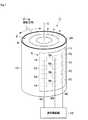
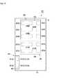
図1ないし図7に、第1の実施の形態によるルネベルグレンズアンテナ装置1(以下、アンテナ装置1という)を示す。アンテナ装置1は、ルネベルグレンズ2と、アレーアンテナ6とを備えている。 1 to 7 show a Luneberg lens antenna apparatus 1 (hereinafter referred to as an antenna apparatus 1) according to a first embodiment. The
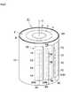
ルネベルグレンズ2は、径方向に対して異なる誘電率の分布を有する円柱状に形成されている。具体的には、ルネベルグレンズ2は、径方向の中心から外側に向けて複数(例えば3層)の誘電体層3〜5が積層されている。誘電体層3〜5は、互いに誘電率ε1〜ε3が異なり、径方向中心(中心軸C)から外側に近付くに従って、徐々に誘電率が小さくなっている。このため、径方向の中心に位置する円柱状の誘電体層3が最も誘電率が大きく、誘電体層3の外周面を覆う円筒状の誘電体層4が2番目に誘電率が大きく、誘電体層4の外周面を覆う円筒状の誘電体層5は誘電率が最も小さくなっている(ε1>ε2>ε3)。これにより、ルネベルグレンズ2は、電波レンズを構成し、所定の周波数の電磁波に対して、その外周面側で周方向の異なる位置に複数の焦点を有する。 The Luneberg
なお、図1には、ルネベルグレンズ2が3層の誘電体層3〜5を備えた場合を例示したが、本発明はこれに限らない。ルネベルグレンズは、2層の誘電体層を備えてもよく、4層以上の誘電体層を備えてもよい。また、誘電率の異なる材料を積み重ねる場合、通常は熱圧着等の手法を用いて積み重ねる。このとき、2つの材料の界面では、相互拡散等の影響により、誘電率が2つの材料のいずれとも異なる層が形成されてもよい。さらに、図1には、誘電率がルネベルグレンズの径方向にステップ状(段階的に)に変化する場合を例示したが、誘電率はルネベルグレンズの径方向にグラデーション状(連続的に)に変化してもよい。 1 illustrates the case where the Luneberg
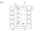
アレーアンテナ6は、複数(例えば12個)のパッチアンテナ7A〜7Cと、給電電極9A〜9Cと、グランド電極11とを備えている。 The
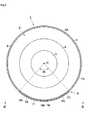
12個のパッチアンテナ7A〜7Cは、ルネベルグレンズ2の外周面2A、即ち最外径側の誘電体層5の外周面に設けられている。これらのパッチアンテナ7A〜7Cは、周方向と軸方向の異なる位置に行列状(4行3列)に配置されている。パッチアンテナ7A〜7Cは、例えばルネベルグレンズ2の周方向および軸方向に広がった長方形状の導体膜(金属膜)によって形成され、給電電極9A〜9Cに接続されている。パッチアンテナ7A〜7Cは、給電電極9A〜9Cからの高周波信号の供給によって、アンテナ素子(放射素子)として機能する。これにより、パッチアンテナ7A〜7Cは、例えばその長さ寸法等に応じて、例えばサブミリ波やミリ波等の高周波信号を送信または受信することができる。 The twelve patch antennas 7 </ b> A to 7 </ b> C are provided on the outer
4個のパッチアンテナ7Aは、周方向に対して同じ位置に配置されると共に、周方向の一方側(図2中の反時計回りの基端側)に位置している。これら4個のパッチアンテナ7Aは、例えば軸方向に等間隔に並んで配置されている。 The four
4個のパッチアンテナ7Bは、周方向に対して同じ位置に配置されると共に、周方向の中央に位置している。このため、4個のパッチアンテナ7Bは、パッチアンテナ7Aとパッチアンテナ7Cとに挟まれた位置に配置されている。これら4個のパッチアンテナ7Bは、例えば軸方向に等間隔に並んで配置されている。 The four
4個のパッチアンテナ7Cは、周方向に対して同じ位置に配置されると共に、周方向の他方側(図2中の反時計回りの終端側)に位置している。これら4個のパッチアンテナ7Cは、例えば軸方向に等間隔に並んで配置されている。パッチアンテナ7Aと、パッチアンテナ7Bと、パッチアンテナ7Cとは、互いに列が異なると共に、互いに独立して高周波信号の送信または受信が可能である。このため、パッチアンテナ7A〜7Cは、例えば周方向に複数の入出力端子をもつMIMOに適用されるものである。また、パッチアンテナ7A〜7Cは、例えば周方向に等間隔に並んで配置されている。 The four
ここで、個々のアンテナの動作をMIMO合成しない個々のアレーアンテナで説明する。図5に示すように、4個のパッチアンテナ7Aは、ルネベルグレンズ2の中心軸Cを挟んで反対側に向けて指向性をもったビームを形成する。即ち、4個のパッチアンテナ7Aは、周方向に対して同じ指向性をもったビームを形成する。 Here, the operation of the individual antennas will be described using individual array antennas that are not MIMO-synthesized. As shown in FIG. 5, the four patch antennas 7 </ b> A form a beam having directivity toward the opposite side across the central axis C of the
また、4個のパッチアンテナ7Aには、給電電極9Aから相互の関係(例えば、位相関係)が予め決められた信号が供給される。これにより、4個のパッチアンテナ7Aによって形成されるビームは、ルネベルグレンズ2の軸方向に対して固定されている。 The four
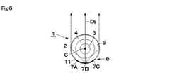
図6に示すように、4個のパッチアンテナ7Bも、パッチアンテナ7Aと同様に、ルネベルグレンズ2の中心軸Cを挟んで反対側に向けて指向性をもったビームを形成する。このとき、パッチアンテナ7Bは、ルネベルグレンズ2の周方向でパッチアンテナ7Aとは異なる位置に配置されている。このため、パッチアンテナ7Bによるビームの放射方向(方向Db)は、パッチアンテナ7Aによるビームの放射方向(方向Da)とは異なっている。 As shown in FIG. 6, the four
一方、4個のパッチアンテナ7Bには、給電電極9Bから相互の関係が予め決められた信号が供給される。これにより、4個のパッチアンテナ7Bによって形成されるビームは、ルネベルグレンズ2の軸方向に対して固定されている。 On the other hand, the four
図7に示すように、4個のパッチアンテナ7Cも、パッチアンテナ7A,7Bと同様に、ルネベルグレンズ2の中心軸Cを挟んで反対側に向けて指向性をもったビームを形成する。このとき、パッチアンテナ7Cは、ルネベルグレンズ2の周方向でパッチアンテナ7A,7Bとは異なる位置に配置されている。このため、パッチアンテナ7Cによるビームの放射方向(方向Dc)は、パッチアンテナ7A,7Bによるビームの放射方向(方向Da,Db)とは異なっている。 As shown in FIG. 7, the four
一方、4個のパッチアンテナ7Cには、給電電極9Cから相互の関係が予め決められた信号が供給される。これにより、4個のパッチアンテナ7Cによって形成されるビームは、ルネベルグレンズ2の軸方向に対して固定されている。 On the other hand, the four
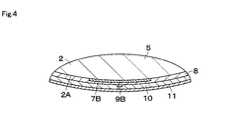
ルネベルグレンズ2の外周面2Aには、全てのパッチアンテナ7A〜7Cを覆って絶縁層8が設けられている。この絶縁層8は、円筒状の被覆部材によって形成され、例えばルネベルグレンズ2の誘電体層5とパッチアンテナ7A〜7Cを密着形成する接着層を含んでいる。このとき、絶縁層8は、誘電体層5よりも小さい誘電率を有することが好ましい。絶縁層8は、ルネベルグレンズ2の外周面2Aを全周に亘って覆っている。 An insulating
給電電極9A〜9Cは、細長い導体膜によって形成され、絶縁層8の外周面に設けられている。給電電極9Aは、4個のパッチアンテナ7Aに沿って軸方向に延び、その先端が4個のパッチアンテナ7Aにそれぞれ接続されている。給電電極9Bは、4個のパッチアンテナ7Bに沿って軸方向に延び、その先端が4個のパッチアンテナ7Bにそれぞれ接続されている。給電電極9Cは、4個のパッチアンテナ7Cに沿って軸方向に延び、その先端が4個のパッチアンテナ7Cにそれぞれ接続されている。給電電極9A〜9Cの基端は、送受信回路12に接続されている。給電電極9A〜9Cは、MIMOの入出力端子を構成している。 The power supply electrodes 9 </ b> A to 9 </ b> C are formed of an elongated conductor film and are provided on the outer peripheral surface of the insulating
絶縁層8の外周面には、給電電極9A〜9Cを覆って絶縁層10が設けられている。この絶縁層10は、絶縁性をもった各種の樹脂材料によって形成されている。絶縁層10は、ルネベルグレンズ2の外周面2Aを全周に亘って覆っている。 An insulating
グランド電極11は、絶縁層10の外周面に設けられている。グランド電極11は、ルネベルグレンズ2の周方向および軸方向に広がった長方形状の導体膜(金属膜)によって形成され、全てのパッチアンテナ7A〜7Cを覆っている。グランド電極11は、外部のグランドに接続され、グランド電位に保持されている。これにより、グランド電極11は、反射器として機能する。 The
このとき、グランド電極11は、ルネベルグレンズ2の中心軸Cに対して180度以下の角度範囲θ1をもって形成されている。これにより、パッチアンテナ7A〜7Cおよびグランド電極11を含むアレーアンテナ6は、ルネベルグレンズ2の全周に対して1/2以下の周方向範囲に形成されている。なお、アレーアンテナ6の角度範囲θ1が大きいと、パッチアンテナ7A〜7Cやグランド電極11の一部が電波を遮る可能性がある。この点を考慮すると、アレーアンテナ6は、90度以下の角度範囲θ1をもって形成され、ルネベルグレンズ2の全周に対して1/4以下の周方向範囲に形成されるのが好ましい。 At this time, the
送受信回路12は、給電電極9A〜9Cを介してパッチアンテナ7A〜7Cに接続されている。送受信回路12は、周方向の位置が互いに異なるパッチアンテナ7A〜7Cに対して、互いに独立した信号を入出力することができる。これにより、送受信回路12は、予め決められた角度範囲θ1に亘ってビームを走査することができる。また、送受信回路12は、パッチアンテナ7A〜7Cのうち少なくとも2つに一緒に給電を行うことによって、複数のビーム(マルチビーム)を形成することができる。なお、本実施の形態では、アレーアンテナ6はアンテナ素子としてパッチアンテナ7A〜7Cを用いた場合を例に挙げて説明したが、パッチアンテナに限定するものではない。例えばアンテナ素子としてスロットアンテナを用いたスロットアレーアンテナ等であってもよい。 The transmission /
次に、本実施の形態によるアンテナ装置1の作動について、図5ないし図7を参照しつつ説明する。 Next, the operation of the
給電電極9Aからパッチアンテナ7Aに向けて給電を行うと、パッチアンテナ7Aには、例えば軸方向に向けて電流が流れる。これにより、パッチアンテナ7Aは、軸方向の寸法に応じた高周波信号を、ルネベルグレンズ2に向けて放射する。この結果、図5に示すように、アンテナ装置1は、ルネベルグレンズ2の中心軸Cを挟んでパッチアンテナ7Aの反対側の方向Daに向けて、高周波信号(ビーム)を放射することができる。また、アンテナ装置1は、パッチアンテナ7Aを用いることによって、方向Daから到来する高周波信号を受信することもできる。 When power is fed from the feeding
同様に、図6に示すように、給電電極9Bからパッチアンテナ7Bに向けて給電したときには、アンテナ装置1は、ルネベルグレンズ2の中心軸Cを挟んでパッチアンテナ7Bの反対側の方向Dbに向けて高周波信号の送信することができると共に、方向Dbからの高周波信号を受信することができる。 Similarly, as shown in FIG. 6, when power is fed from the feeding
図7に示すように、給電電極9Cからパッチアンテナ7Cに向けて給電したときには、アンテナ装置1は、ルネベルグレンズ2の中心軸Cを挟んでパッチアンテナ7Cの反対側の方向Dcに向けて高周波信号の送信することができると共に、方向Dcからの高周波信号を受信することができる。 As shown in FIG. 7, when power is fed from the feeding
また、パッチアンテナ7Aとパッチアンテナ7Bとの両方を用いることによって、ビームの放射方向を方向Daと方向Dbとの間でビーム調整してもよい。同様に、パッチアンテナ7Bとパッチアンテナ7Cとの両方を用いることによって、ビームの放射方向を方向Dbと方向Dcとの間でビーム調整してもよい。これにより、アンテナ装置1は、方向Daから方向Dcの間で、任意の方向に向けてビームを放射することができる。 Further, by using both the
なお、パッチアンテナ7A〜7Cには、軸方向の電流を流し、垂直偏波の電磁波を放射した場合について説明した。本発明はこれに限らず、パッチアンテナ7A〜7Cには、周方向の電流を流し、水平偏波の電磁波を放射してもよいし、円偏波等でもよい。 Note that the case where an axial current is passed through the
かくして、第1の実施の形態では、アレーアンテナ6は、ルネベルグレンズ2の外周面2A側であってルネベルグレンズ2の周方向の異なる焦点位置に配置された複数のパッチアンテナ7A〜7Cを備える構成した。このため、周方向の異なる位置に設けられた複数のパッチアンテナ7A〜7Cを用いることによって、互いに異なる方向に向けて低サイドローブのビームを形成することができる。また、パッチアンテナ7A〜7Cを独立して一緒に動作させることによって、マルチビームの形成が可能になる。さらに、軸方向の異なる位置に複数のパッチアンテナ7A〜7Cを設けたから、例えば軸方向に対してビームを絞ることができ、アンテナ利得を高めることができる。 Thus, in the first embodiment, the
これに加え、アレーアンテナ6は、ルネベルグレンズ2のうち全周の1/2以下の周方向範囲に設けられているから、アレーアンテナ6の周方向範囲に応じて周方向にビームを走査することができる。 In addition to this, the
また、円柱状のルネベルグレンズ2を用いるから、ルネベルグレンズ2の外周面2A側に信号用の接続線路となる給電電極9A〜9Cを形成することができる。このため、アンテナ装置1は、球形状のルネベルグレンズを用いた場合に比べて容易に信号を取り出すことができる。 Further, since the
さらに、アレーアンテナ6は、ルネベルグレンズ2の軸方向の異なる位置に配置された複数のパッチアンテナ7A〜7Cが相互に従属して動作する構成とした。このとき、ルネベルグレンズ2の軸方向の異なる位置に配置された複数のパッチアンテナ(例えば、4個のパッチアンテナ7A)は、MIMO構成ではなく、ルネベルグレンズ2の周方向の異なる位置に配置された複数のパッチアンテナ7A〜7CがMIMO構成とすることができる。このため、軸方向に並ぶ4個のパッチアンテナ7Aには、例えば位相差が固定された信号のように、互いに決められた所定関係の信号を供給して、軸方向には固定のビームを形成することができる。この点は、パッチアンテナ7B,7Cも同様である。このため、軸方向に並ぶ複数のパッチアンテナ7A〜7Cは、例えば固定的な移相器等のような受動回路によって互いに接続することができる。従って、周方向の異なる位置に設けた3列のパッチアンテナ7A〜7Cについて、独立した信号を供給すればよく、送受信回路12の入出力回路を低減して、その構成を簡略化することができる。 Furthermore, the
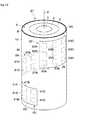
次に、図8および図9に、本発明の第2の実施の形態によるルネベルグレンズアンテナ装置21(以下、アンテナ装置21という)を示す。第2の実施の形態の特徴は、周方向の異なる位置に設けられた3列のパッチアンテナ7A〜7Cに応じて、3個のグランド電極23A〜23Cを互いに分離して設けたことにある。なお、アンテナ装置21の説明に際し、第1の実施の形態によるアンテナ装置1と同一の構成については同一の符号を付し、その説明は省略する。 Next, FIGS. 8 and 9 show a Luneberg lens antenna device 21 (hereinafter referred to as the antenna device 21) according to a second embodiment of the present invention. The feature of the second embodiment is that three
第2の実施の形態によるアンテナ装置21は、第1の実施の形態によるアンテナ装置1とほぼ同様に構成される。このため、アンテナ装置21は、ルネベルグレンズ2と、アレーアンテナ22とを備える。 The
第2の実施の形態によるアレーアンテナ22は、第1の実施の形態によるアレーアンテナ6とほぼ同様に構成される。このため、アレーアンテナ22は、パッチアンテナ7A〜7Cと、給電電極9A〜9Cと、グランド電極23A〜23Cとを備えている。 The
但し、グランド電極23A〜23Cは、周方向の異なる位置に設けられた3列のパッチアンテナ7A〜7Cに応じて、周方向に分離して設けられている。この点で、グランド電極23A〜23Cは、全てのパッチアンテナ7A〜7Cを覆って設けられた第1の実施の形態によるグランド電極11とは異なっている。 However, the
グランド電極23A〜23Cは、例えば軸方向に延びた長方形状に形成され、絶縁層10の外周面に設けられている。グランド電極23Aは、4個のパッチアンテナ7Aを覆っている。グランド電極23Bは、4個のパッチアンテナ7Bを覆っている。グランド電極23Cは、4個のパッチアンテナ7Cを覆っている。グランド電極23A〜23Cは、周方向に互いに等間隔に離間した位置に配置されている。 The ground electrodes 23 </ b> A to 23 </ b> C are formed in, for example, a rectangular shape extending in the axial direction, and are provided on the outer peripheral surface of the insulating
かくして、第2の実施の形態でも、第1の実施の形態と同様の作用効果を得ることができる。また、第1の実施の形態のように、単一のグランド電極11を用いた場合には、例えばグランド電極11の端部で電磁波の回折現象等が生じる傾向がある。このため、第1の実施の形態では、周方向の端部側に位置するパッチアンテナ7A,7Cによって形成されたビームと、周方向の中央に位置するパッチアンテナ7Bによって形成されたビームとでは、ビーム幅やサイドローブの形状等が互いに異なる傾向がある。 Thus, also in the second embodiment, it is possible to obtain the same effects as those in the first embodiment. Further, when a
これに対し、第2の実施の形態では、周方向の異なる位置に設けられた3列のパッチアンテナ7A〜7Cに応じて、3個のグランド電極23A〜23Cを互いに分離して設けた。このため、パッチアンテナ7A〜7Cによるビームについて、ビーム幅やサイドローブの形状等を互いに略同じ形状に形成することができる。 On the other hand, in the second embodiment, the three
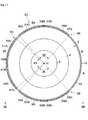
次に、図10ないし図12に、本発明の第3の実施の形態によるルネベルグレンズアンテナ装置31(以下、アンテナ装置31という)を示す。第3の実施の形態の特徴は、ルネベルグレンズには、軸方向の異なる位置に複数のアレーアンテナを設けたことにある。なお、アンテナ装置31の説明に際し、第1の実施の形態によるアンテナ装置1と同一の構成については同一の符号を付し、その説明は省略する。 Next, FIGS. 10 to 12 show a Luneberg lens antenna apparatus 31 (hereinafter referred to as an antenna apparatus 31) according to a third embodiment of the present invention. The feature of the third embodiment is that the Luneberg lens is provided with a plurality of array antennas at different positions in the axial direction. In the description of the
第3の実施の形態によるアンテナ装置31は、第1の実施の形態によるアンテナ装置1とほぼ同様に構成される。このため、アンテナ装置31は、ルネベルグレンズ2と、アレーアンテナ32,36,40とを備える。但し、アンテナ装置31は、軸方向の異なる位置に設けられた3個のアレーアンテナ32,36,40を備える点で、第1の実施の形態によるアンテナ装置1とは異なっている。 The
アレーアンテナ32は、第1の実施の形態によるアレーアンテナ6とほぼ同様に構成される。このため、アレーアンテナ32は、例えば3行3列のパッチアンテナ33A〜33Cと、給電電極34A〜34Cと、グランド電極35とを備えている。アレーアンテナ32は、ルネベルグレンズ2の中心軸Cを中心として90度以下の角度範囲θ1に亘って形成され、ルネベルグレンズ2の全周に対して1/2以下、好ましくは1/4以下の周方向範囲に形成されている。 The
アレーアンテナ32は、例えばルネベルグレンズ2の軸方向に対して最上部側に位置している。このアレーアンテナ32は、他のアレーアンテナ36,40に比べて、軸方向の配列数(行数)が多いパッチアンテナ33A〜33Cを備えている。このため、アレーアンテナ32によるビームは、アレーアンテナ36,40によるビームに比べて、軸方向のビーム幅が狭くなっている。この結果、アレーアンテナ32は、高利得となり、近傍範囲に限らず遠方範囲までビームを到達させることができる。 The
アレーアンテナ36は、例えば2行3列のパッチアンテナ37A〜37Cと、給電電極38A〜38Cと、グランド電極39とを備えている。アレーアンテナ36は、ルネベルグレンズ2の中心軸Cを中心として90度以下の角度範囲θ2に亘って形成され、ルネベルグレンズ2の全周に対して1/2以下、好ましくは1/4以下の周方向範囲に形成されている。 The
アレーアンテナ36は、例えばルネベルグレンズ2の軸方向に対してアレーアンテナ32の下側で、かつアレーアンテナ40の上側に位置している。アレーアンテナ36は、アレーアンテナ32に比べて、軸方向の配列数(行数)が少ないパッチアンテナ37A〜37Cを備えている。このため、アレーアンテナ36によるビームは、アレーアンテナ32によるビームに比べて、軸方向のビーム幅が広くなっている。この結果、アレーアンテナ36は、低利得となり、近傍範囲にビームを到達させることができる。 For example, the
アレーアンテナ40は、例えば2行3列のパッチアンテナ41A〜41Cと、給電電極42A〜42Cと、グランド電極43とを備えている。アレーアンテナ40は、ルネベルグレンズ2の中心軸Cを中心として90度以下の角度範囲θ3に亘って形成され、ルネベルグレンズ2の全周に対して1/2以下、好ましくは1/4以下の周方向範囲に形成されている。 The
アレーアンテナ40は、例えばルネベルグレンズ2の軸方向に対して最下部側に位置している。アレーアンテナ40は、アレーアンテナ36と同様に、アレーアンテナ32に比べて、軸方向の配列数(行数)が少ないパッチアンテナ41A〜41Cを備えている。このため、アレーアンテナ40によるビームは、アレーアンテナ32によるビームに比べて、軸方向のビーム幅が広くなっている。 The
このように、3個のアレーアンテナ32,36,40は、ルネベルグレンズ2の軸方向に対して互いに異なる位置に配置されている。これに加え、アレーアンテナ32,36,40は、ルネベルグレンズ2の周方向に対して互いに異なる位置に配置されている。このとき、図11に示すように、アレーアンテナ36の周方向の他方側端部(パッチアンテナ37Cが配置された図11中の反時計回りの終端部)は、アレーアンテナ40の周方向の一方側端部(パッチアンテナ41Aが配置された図11中の反時計回りの基端部)に隣接した位置に配置されている。また、アレーアンテナ40の周方向の他方側端部(パッチアンテナ41Cが配置された図11中の反時計回りの終端部)は、アレーアンテナ32の周方向の一方側端部(パッチアンテナ33Aが配置された図11中の反時計回りの基端部)に隣接した位置に配置されている。この結果、3個のアレーアンテナ32,36,40は、角度範囲θ1〜θ3を加え合わせた角度範囲に亘って、ビームを放射することができる。 As described above, the three
なお、図10および図11に示すように、3個のアレーアンテナ32,36,40を効率的に配置するためには、ルネベルグレンズ2の上方から見下ろしたときに、3個のアレーアンテナ32,36,40が重ならないように配置されていることが好ましい。しかしながら、本発明はこれに限らない。例えば、第1のアレーアンテナは0〜90度の角度範囲に配置され、第2のアレーアンテナは0〜110度の角度範囲に配置され、第3のアレーアンテナは0〜140度の角度範囲に配置されたときのように、一部の角度範囲(例えば、0〜90度の角度範囲)が互いに重複してもよい。即ち、例えば軸方向の異なる位置に設けられた複数のアレーアンテナは、互いの周方向範囲の少なくとも一部が異なっていればよく、周方向範囲が部分的に重複してもよい。 As shown in FIGS. 10 and 11, in order to efficiently arrange the three
かくして、第3の実施の形態でも、第1の実施の形態と同様の作用効果を得ることができる。また、第3の実施の形態では、ルネベルグレンズ2には、軸方向の異なる位置に複数のアレーアンテナ32,36,40が設けられるから、単一のアレーアンテナを用いた場合に比べて、ビーム走査が可能な角度範囲を拡大することができる。 Thus, in the third embodiment, it is possible to obtain the same operational effects as in the first embodiment. In the third embodiment, the
さらに、アレーアンテナ32のパッチアンテナ33A〜33Cは、他のアレーアンテナ36,40のパッチアンテナ37A〜37C,41A〜41Cに比べて、軸方向の配列数が多い構成とした。このため、アレーアンテナ32では、指向性の高いビームを形成して、遠方までビームを到達させることができる。一方、アレーアンテナ36,40では、指向性の低いビームを形成して、近傍の広い角度範囲に亘ってビームを到達させることができる。このため、周方向に対して必要な特性が異なるときでも、その要求仕様に応じて、ビームの形状を設定することができる。 Further, the
また、軸方向で隣合うアレーアンテナ32,36は、互いの角度範囲がルネベルグレンズ2を挟んで180度異なる位置に配置されている。このため、アレーアンテナ32とアレーアンテナ36との間に、例えば周方向に対して90度以上の角度範囲をもった隙間を形成することができる。この結果、アレーアンテナ32,36との間で、ビームの相互作用を抑制することができる。 Further, the
なお、第3の実施の形態では、3個のアレーアンテナ32,36,40を備えることによって、略270度の角度範囲に亘ってビームを走査可能とした。本発明はこれに限らず、例えば90度程度の角度範囲をもったアレーアンテナを4個備えることによって、全周(360度)に亘ってビームを走査可能としてもよい。 In the third embodiment, by providing the three
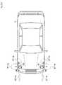
次に、図13に、本発明の第4の実施の形態によるルネベルグレンズアンテナ装置51,52(以下、アンテナ装置51,52という)を示す。第4の実施の形態の特徴は、アンテナ装置51,52を自動車Vの車載レーダに適用したことにある。なお、アンテナ装置51,52の説明に際し、第3の実施の形態によるアンテナ装置31と同一の構成については同一の符号を付し、その説明は省略する。 Next, FIG. 13 shows Luneberg
アンテナ装置51は、第3の実施の形態によるアンテナ装置31とほぼ同様に構成され、アレーアンテナ32,36,40を備えている。アンテナ装置51は、自動車Vに左側に設けられている。アレーアンテナ32は、ルネベルグレンズ2のうち後方位置に配置されている。アレーアンテナ36は、ルネベルグレンズ2のうち前方位置に配置されている。アレーアンテナ40は、ルネベルグレンズ2のうち右側位置に配置されている。これにより、アンテナ装置51は、自動車Vの前方、左側方および後方に向けてビームが放射可能となっている。 The
アンテナ装置52は、第3の実施の形態によるアンテナ装置31とほぼ同様に構成され、アレーアンテナ32,36,40を備えている。アンテナ装置52は、自動車Vに右側に設けられている。アレーアンテナ32は、ルネベルグレンズ2のうち後方位置に配置されている。アレーアンテナ36は、ルネベルグレンズ2のうち前方位置に配置されている。アレーアンテナ40は、ルネベルグレンズ2のうち左側位置に配置されている。これにより、アンテナ装置52は、自動車Vの前方、右側方および後方に向けてビームが放射可能となっている。The
かくして、第4の実施の形態でも、第3の実施の形態と同様の作用効果を得ることができる。また、第4の実施の形態では、アンテナ装置51,52は、高利得のアレーアンテナ32によって、自動車Vの前側に向けてビームを放射する。このため、アンテナ装置51,52は、例えば遠方に位置する先行車等を探知することができる。一方、アンテナ装置51,52は、低利得のアレーアンテナ36,40によって、自動車Vの後方および側方に向けて広角のビームを放射する。これより、自動車Vの後方および左側方、右側方については、広い近傍範囲の障害物を探知することができる。 Thus, in the fourth embodiment, the same function and effect as in the third embodiment can be obtained. In the fourth embodiment, the
なお、前記第1の実施の形態では、アレーアンテナ6は、パッチアンテナ7A〜7Cとグランド電極11との間に給電電極9A〜9Cを設ける構成とした。本発明はこれに限らず、グランド電極の径方向外側に給電電極を設け、グランド電極に設けたスルーホール等を通じて、給電電極をパッチアンテナに接続する構成としてもよい。この構成は、第2ないし第4の実施の形態にも適用することができる。 In the first embodiment, the
前記第1の実施の形態では、アレーアンテナ6は、4行3列のマトリクス状に配置された12個のパッチアンテナ7A〜7Cを備えるものとした。本発明はこれに限らず、パッチアンテナの個数や配置は、アレーアンテナの仕様等に応じて適宜設定することができる。この構成は、第2ないし第4の実施の形態にも適用することができる。 In the first embodiment, the
前記第1の実施の形態では、アレーアンテナ6は、ルネベルグレンズ2の軸方向の異なる位置に配置された複数のパッチアンテナ(例えば、4個のパッチアンテナ7A)が相互に従属して動作する構成とした。本発明はこれに限らず、アレーアンテナは、軸方向に異なる位置に設けられた複数のパッチアンテナに独立した信号を供給して、相互に独立して動作してもよい。この場合には、例えば軸方向のビームの放射方向や形状を調整することができる。この構成は、第2ないし第4の実施の形態にも適用することができる。 In the first embodiment, the
前記第3の実施の形態では、アレーアンテナ32,36,40は、いずれも周方向の異なる位置に3列のパッチアンテナ33A〜33C,37A〜37C,41A〜41Cを備えるものとした。本発明はこれに限らず、例えば軸方向の異なる位置に設けられた複数のアレーアンテナは、周方向に異なる配列数のパッチアンテナを備える構成としてもよい。この構成は、第4の実施の形態にも適用することができる。 In the third embodiment, each of the
前記第3の実施の形態では、ルネベルグレンズ2の軸方向の異なる位置に設けられたアレーアンテナ32のパッチアンテナ33A〜33Cと、アレーアンテナ36,40のパッチアンテナ37A〜37C,41A〜41Cとは、軸方向の配列数が異なる構成とした。本発明はこれに限らず、軸方向の異なる位置に設けられた複数のアレーアンテナは、パッチアンテナの軸方向の配列数が互いに同数であってもよい。この場合、例えばルネベルグレンズアンテナ装置を移動体通信用の基地局に用いる場合には、全方位に向けて均質なビームを放射することができる。 In the third embodiment, the
前記各実施の形態は例示であり、異なる実施の形態で示した構成の部分的な置換または組み合わせが可能であることは言うまでもない。 It is needless to say that each of the embodiments described above is an exemplification, and partial replacement or combination of the configurations shown in the different embodiments is possible.
1,21,31,51,52 ルネベルグレンズアンテナ装置(アンテナ装置)
2 ルネベルグレンズ
3〜5 誘電体層
6,22,32,36,40 アレーアンテナ
7A〜7C,33A〜33C,37A〜37C,41A〜41C パッチアンテナ
9A〜9C,34A〜34C,38A〜38C,42A〜42C 給電電極
11,23A〜23C,35,39,43 グランド電極
12 送受信回路1, 21, 31, 51, 52 Luneberg lens antenna device (antenna device)
2 Luneberg lenses 3-5 Dielectric layers 6, 22, 32, 36, 40
Claims (4)
Translated fromJapanese前記ルネベルグレンズの外周面側であって前記ルネベルグレンズの周方向および軸方向の異なる焦点位置に行列状に配置された複数のパッチアンテナを有したアレーアンテナとを備え、
前記アレーアンテナは、前記ルネベルグレンズのうち全周の1/2以下の周方向範囲に設けられ、
前記ルネベルグレンズの外周面側には、周方向の異なる位置に設けられた複数列の前記パッチアンテナに応じて、周方向に分離した複数のグランド電極が設けられ、
複数の前記グランド電極は、各列の前記パッチアンテナをそれぞれ覆ってなるルネベルグレンズアンテナ装置。A cylindrical Luneberg lens having a distribution of dielectric constants different from each other in the radial direction;
An array antenna having a plurality ofpatch antennas arranged in amatrix at different focal positions in the circumferential direction and the axial direction of the Luneberg lens on the outer peripheral surface side of the Luneberg lens;
The array antenna is provided in a circumferential direction range of 1/2 or less of the entire circumference of the Luneberg lens,
A plurality of ground electrodes separated in the circumferential direction are provided on the outer peripheral surface side of the Luneberg lens according to the plurality of rows of patch antennas provided at different positions in the circumferential direction.
The plurality of ground electrodes are Luneberg lens antenna deviceseach covering thepatch antenna in each row .
複数の前記アレーアンテナは、互いの周方向範囲の少なくとも一部が異なってなる請求項1に記載のルネベルグレンズアンテナ装置。The Luneberg lens is provided with a plurality of the array antennas at different positions in the axial direction,
2. The Luneberg lens antenna apparatus according to claim 1, wherein the plurality of array antennas are different from each other in at least part of a circumferential range.
Applications Claiming Priority (3)
| Application Number | Priority Date | Filing Date | Title |
|---|---|---|---|
| JP2015228645 | 2015-11-24 | ||
| JP2015228645 | 2015-11-24 | ||
| PCT/JP2016/082630WO2017090401A1 (en) | 2015-11-24 | 2016-11-02 | Luneberg lens antenna device |
Publications (2)
| Publication Number | Publication Date |
|---|---|
| JPWO2017090401A1 JPWO2017090401A1 (en) | 2018-08-30 |
| JP6497447B2true JP6497447B2 (en) | 2019-04-10 |
Family
ID=58763139
Family Applications (1)
| Application Number | Title | Priority Date | Filing Date |
|---|---|---|---|
| JP2017552338AActiveJP6497447B2 (en) | 2015-11-24 | 2016-11-02 | Luneberg lens antenna device |
Country Status (5)
| Country | Link |
|---|---|
| US (1) | US10777902B2 (en) |
| EP (1) | EP3382800B1 (en) |
| JP (1) | JP6497447B2 (en) |
| CN (1) | CN108292807B (en) |
| WO (1) | WO2017090401A1 (en) |
Families Citing this family (25)
| Publication number | Priority date | Publication date | Assignee | Title |
|---|---|---|---|---|
| EP3401999B1 (en)* | 2016-01-07 | 2020-10-07 | Murata Manufacturing Co., Ltd. | Luneberg lens antenna device |
| US11283189B2 (en) | 2017-05-02 | 2022-03-22 | Rogers Corporation | Connected dielectric resonator antenna array and method of making the same |
| DE112018002832T5 (en)* | 2017-06-30 | 2020-02-20 | Murata Manufacturing Co., Ltd. | DIELECTRIC LENS |
| CN107959122B (en)* | 2017-08-18 | 2019-03-12 | 西安肖氏天线科技有限公司 | A kind of ultralight artificial dielectric multilayer cylindrical lens |
| US11616302B2 (en) | 2018-01-15 | 2023-03-28 | Rogers Corporation | Dielectric resonator antenna having first and second dielectric portions |
| US10893349B2 (en)* | 2018-03-30 | 2021-01-12 | Audio-Technica U.S., Inc. | Wireless microphone comprising a plurality of antennas |
| WO2019216181A1 (en)* | 2018-05-09 | 2019-11-14 | 住友電気工業株式会社 | Lens, antenna, and on-board apparatus |
| CN117082455A (en)* | 2018-06-01 | 2023-11-17 | X开发有限责任公司 | Intelligent tracking system and method and system thereof |
| US11552390B2 (en)* | 2018-09-11 | 2023-01-10 | Rogers Corporation | Dielectric resonator antenna system |
| WO2020117489A1 (en) | 2018-12-04 | 2020-06-11 | Rogers Corporation | Dielectric electromagnetic structure and method of making the same |
| WO2020139607A1 (en)* | 2018-12-28 | 2020-07-02 | Saint-Gobain Performance Plastics Corporation | Continuous dielectric constant adaptation radome design |
| US10910712B2 (en)* | 2019-01-14 | 2021-02-02 | Raytheon Company | Active electronically scanned array (AESA) antenna configuration for simultaneous transmission and receiving of communication signals |
| US11715060B2 (en) | 2019-05-31 | 2023-08-01 | X Development Llc | Intelligent tracking system and methods and systems therefor |
| CN112151967B (en)* | 2019-06-26 | 2022-12-02 | 合肥若森智能科技有限公司 | Luneberg lens antenna |
| CN114631232A (en)* | 2019-10-21 | 2022-06-14 | 株式会社村田制作所 | Circularly polarized array antenna device |
| CN115087883A (en)* | 2019-11-25 | 2022-09-20 | 伦威夫公司 | Automobile radar based on gradient refractive index lens |
| CN110988870B (en)* | 2019-12-20 | 2023-08-18 | 北京工业大学 | Millimeter wave imaging system |
| US11482790B2 (en) | 2020-04-08 | 2022-10-25 | Rogers Corporation | Dielectric lens and electromagnetic device with same |
| CN112068110B (en)* | 2020-07-14 | 2022-05-03 | 南京航空航天大学 | An underwater obstacle detector based on Lumbert lens |
| US11929556B2 (en) | 2020-09-08 | 2024-03-12 | Raytheon Company | Multi-beam passively-switched patch antenna array |
| KR102678972B1 (en) | 2021-04-22 | 2024-07-03 | 한국전자통신연구원 | Acoustic luneburg meta lens and design method thereof |
| CN113270724B (en)* | 2021-05-18 | 2022-03-29 | 电子科技大学 | High-gain wide-angle scanning multi-beam manhole cover antenna based on Lumberg lens |
| CN115882219B (en)* | 2021-09-29 | 2025-09-26 | 华为技术有限公司 | Antenna systems and electronics |
| CN114552227B (en)* | 2022-04-27 | 2022-07-26 | 电子科技大学 | Planar luneberg lens antenna based on sparse phased array feed |
| CN116505292B (en)* | 2023-06-29 | 2023-09-08 | 西安海天天线科技股份有限公司 | Multi-stream omni-directional antenna equipment based on metamaterial lens technology |
Family Cites Families (13)
| Publication number | Priority date | Publication date | Assignee | Title |
|---|---|---|---|---|
| US3307187A (en)* | 1966-03-11 | 1967-02-28 | Armstrong Cork Co | Omniazimuthal reflectors |
| FR2165792B1 (en)* | 1971-12-31 | 1976-10-29 | Thomson Csf | |
| DE4430832A1 (en)* | 1994-05-23 | 1995-11-30 | Horn Wolfgang | Multiple beam aerial with transmission and receiving equipment |
| US6426814B1 (en) | 1999-10-13 | 2002-07-30 | Caly Corporation | Spatially switched router for wireless data packets |
| IL149083A0 (en)* | 1999-10-13 | 2002-11-10 | Caly Corp | Spatially switched router for wireless data packets |
| FR2807216B1 (en) | 2000-03-31 | 2002-06-21 | Thomson Csf | DEVICE FOR MOTORIZING SENSORS IN A RECEIVER AND / OR TRANSMITTER WITH A SPHERICAL ELECTROMAGNETIC LENS, AND RECEIVER AND / OR TRANSMITTER COMPRISING SUCH A DEVICE |
| JP2006054730A (en)* | 2004-08-12 | 2006-02-23 | Kobe Steel Ltd | Antenna system, and radiation characteristic control method |
| JP5208005B2 (en) | 2009-01-29 | 2013-06-12 | 日本無線株式会社 | Patch array antenna |
| CN102122762B (en)* | 2011-01-25 | 2013-08-07 | 浙江大学 | Millimeter wave 360o omnidirectional scanning dielectric cylindrical lens antenna |
| JP2013130466A (en)* | 2011-12-21 | 2013-07-04 | Hitachi Ltd | Electromagnetic wave visualization apparatus |
| US8854257B2 (en)* | 2012-10-22 | 2014-10-07 | The United States Of America As Represented By The Secretary Of The Army | Conformal array, luneburg lens antenna system |
| US9780457B2 (en)* | 2013-09-09 | 2017-10-03 | Commscope Technologies Llc | Multi-beam antenna with modular luneburg lens and method of lens manufacture |
| EP3401999B1 (en)* | 2016-01-07 | 2020-10-07 | Murata Manufacturing Co., Ltd. | Luneberg lens antenna device |
- 2016
- 2016-11-02CNCN201680068305.3Apatent/CN108292807B/enactiveActive
- 2016-11-02JPJP2017552338Apatent/JP6497447B2/enactiveActive
- 2016-11-02WOPCT/JP2016/082630patent/WO2017090401A1/enunknown
- 2016-11-02EPEP16868350.6Apatent/EP3382800B1/enactiveActive
- 2018
- 2018-05-23USUS15/987,291patent/US10777902B2/enactiveActive
Also Published As
| Publication number | Publication date |
|---|---|
| CN108292807B (en) | 2021-02-02 |
| EP3382800B1 (en) | 2021-08-04 |
| WO2017090401A1 (en) | 2017-06-01 |
| CN108292807A (en) | 2018-07-17 |
| EP3382800A1 (en) | 2018-10-03 |
| US10777902B2 (en) | 2020-09-15 |
| US20180269586A1 (en) | 2018-09-20 |
| JPWO2017090401A1 (en) | 2018-08-30 |
| EP3382800A4 (en) | 2019-06-12 |
Similar Documents
| Publication | Publication Date | Title |
|---|---|---|
| JP6497447B2 (en) | Luneberg lens antenna device | |
| US10468777B2 (en) | Luneburg lens antenna device | |
| US10910700B2 (en) | Omnidirectional antenna for mobile communication service | |
| US9379437B1 (en) | Continuous horn circular array antenna system | |
| US11777221B2 (en) | Antenna module | |
| WO2019102869A1 (en) | High-frequency module and communication device | |
| JP6536376B2 (en) | Luneberg lens antenna device | |
| US20150340770A1 (en) | Antenna Assembly and System | |
| US8912970B1 (en) | Antenna element with integral faraday cage | |
| US10439283B2 (en) | High coverage antenna array and method using grating lobe layers | |
| JP7358880B2 (en) | Dual polarization array antenna and its manufacturing method | |
| US11909103B2 (en) | Base station antennas having staggered linear arrays with improved phase center alignment between adjacent arrays | |
| CN112133999B (en) | Base station antenna | |
| WO2017119222A1 (en) | Luneberg lens antenna device | |
| JP2000269735A (en) | Array antenna | |
| US12206173B1 (en) | Dual mode omni / directional sectored array | |
| WO2015159871A1 (en) | Antenna and sector antenna | |
| US20220037798A1 (en) | Lens integrated planar programmable polarized and beamsteering antenna array | |
| KR102048355B1 (en) | antenna module having monopole antenna with multi band circular polarization | |
| KR102394771B1 (en) | Antenna apparatus and identification of friend or foe system with the same | |
| US9356353B1 (en) | Cog ring antenna for phased array applications | |
| EP1564843A1 (en) | Circular polarised array antenna |
Legal Events
| Date | Code | Title | Description |
|---|---|---|---|
| A621 | Written request for application examination | Free format text:JAPANESE INTERMEDIATE CODE: A621 Effective date:20180417 | |
| A131 | Notification of reasons for refusal | Free format text:JAPANESE INTERMEDIATE CODE: A131 Effective date:20181204 | |
| A521 | Request for written amendment filed | Free format text:JAPANESE INTERMEDIATE CODE: A523 Effective date:20190129 | |
| TRDD | Decision of grant or rejection written | ||
| A01 | Written decision to grant a patent or to grant a registration (utility model) | Free format text:JAPANESE INTERMEDIATE CODE: A01 Effective date:20190212 | |
| A61 | First payment of annual fees (during grant procedure) | Free format text:JAPANESE INTERMEDIATE CODE: A61 Effective date:20190225 | |
| R150 | Certificate of patent or registration of utility model | Ref document number:6497447 Country of ref document:JP Free format text:JAPANESE INTERMEDIATE CODE: R150 |