JP6494352B2 - Liquid discharge head - Google Patents
Liquid discharge headDownload PDFInfo
- Publication number
- JP6494352B2 JP6494352B2JP2015059403AJP2015059403AJP6494352B2JP 6494352 B2JP6494352 B2JP 6494352B2JP 2015059403 AJP2015059403 AJP 2015059403AJP 2015059403 AJP2015059403 AJP 2015059403AJP 6494352 B2JP6494352 B2JP 6494352B2
- Authority
- JP
- Japan
- Prior art keywords
- liquid
- liquid tank
- tank
- discharge head
- liquid discharge
- Prior art date
- Legal status (The legal status is an assumption and is not a legal conclusion. Google has not performed a legal analysis and makes no representation as to the accuracy of the status listed.)
- Active
Links
Images


Classifications
- B—PERFORMING OPERATIONS; TRANSPORTING
- B41—PRINTING; LINING MACHINES; TYPEWRITERS; STAMPS
- B41J—TYPEWRITERS; SELECTIVE PRINTING MECHANISMS, i.e. MECHANISMS PRINTING OTHERWISE THAN FROM A FORME; CORRECTION OF TYPOGRAPHICAL ERRORS
- B41J2/00—Typewriters or selective printing mechanisms characterised by the printing or marking process for which they are designed
- B41J2/005—Typewriters or selective printing mechanisms characterised by the printing or marking process for which they are designed characterised by bringing liquid or particles selectively into contact with a printing material
- B41J2/01—Ink jet
- B41J2/135—Nozzles
- B41J2/14—Structure thereof only for on-demand ink jet heads
- B41J2/1433—Structure of nozzle plates
- B—PERFORMING OPERATIONS; TRANSPORTING
- B41—PRINTING; LINING MACHINES; TYPEWRITERS; STAMPS
- B41J—TYPEWRITERS; SELECTIVE PRINTING MECHANISMS, i.e. MECHANISMS PRINTING OTHERWISE THAN FROM A FORME; CORRECTION OF TYPOGRAPHICAL ERRORS
- B41J2/00—Typewriters or selective printing mechanisms characterised by the printing or marking process for which they are designed
- B41J2/005—Typewriters or selective printing mechanisms characterised by the printing or marking process for which they are designed characterised by bringing liquid or particles selectively into contact with a printing material
- B41J2/01—Ink jet
- B41J2/17—Ink jet characterised by ink handling
- B41J2/175—Ink supply systems ; Circuit parts therefor
- B41J2/17503—Ink cartridges
- B41J2/1752—Mounting within the printer
- B—PERFORMING OPERATIONS; TRANSPORTING
- B41—PRINTING; LINING MACHINES; TYPEWRITERS; STAMPS
- B41J—TYPEWRITERS; SELECTIVE PRINTING MECHANISMS, i.e. MECHANISMS PRINTING OTHERWISE THAN FROM A FORME; CORRECTION OF TYPOGRAPHICAL ERRORS
- B41J2/00—Typewriters or selective printing mechanisms characterised by the printing or marking process for which they are designed
- B41J2/005—Typewriters or selective printing mechanisms characterised by the printing or marking process for which they are designed characterised by bringing liquid or particles selectively into contact with a printing material
- B41J2/01—Ink jet
- B41J2/17—Ink jet characterised by ink handling
- B41J2/175—Ink supply systems ; Circuit parts therefor
- B41J2/17503—Ink cartridges
- B41J2/17553—Outer structure
- B—PERFORMING OPERATIONS; TRANSPORTING
- B41—PRINTING; LINING MACHINES; TYPEWRITERS; STAMPS
- B41J—TYPEWRITERS; SELECTIVE PRINTING MECHANISMS, i.e. MECHANISMS PRINTING OTHERWISE THAN FROM A FORME; CORRECTION OF TYPOGRAPHICAL ERRORS
- B41J2/00—Typewriters or selective printing mechanisms characterised by the printing or marking process for which they are designed
- B41J2/005—Typewriters or selective printing mechanisms characterised by the printing or marking process for which they are designed characterised by bringing liquid or particles selectively into contact with a printing material
- B41J2/01—Ink jet
- B41J2/135—Nozzles
- B41J2/14—Structure thereof only for on-demand ink jet heads
- B41J2002/14491—Electrical connection
Landscapes
- Ink Jet (AREA)
Description
Translated fromJapanese本発明は、液体吐出装置に搭載される液体吐出ヘッドに関する。 The present invention relates to a liquid discharge head mounted on a liquid discharge apparatus.
インクジェット方式の記録装置に代表される液体吐出装置では、インク等の液体を貯留する液体タンクが液体吐出ヘッドに搭載されることがある。この方式によれば液体が液体タンクから液体吐出ヘッドに直接供給されるため、液体タンクと液体吐出ヘッドを連絡するチューブなどが不要であり、コンパクトで安価な液体吐出装置を提供することができる。 In a liquid ejection apparatus typified by an ink jet recording apparatus, a liquid tank that stores a liquid such as ink may be mounted on a liquid ejection head. According to this method, since the liquid is directly supplied from the liquid tank to the liquid discharge head, a tube for connecting the liquid tank and the liquid discharge head is unnecessary, and a compact and inexpensive liquid discharge apparatus can be provided.
特許文献1にはこのような液体吐出ヘッドが開示されている。液体吐出ヘッドの液体タンク収容空間は、液体タンクの四方を取り囲む周囲壁と、液体タンクの挿入方向前方に位置する側壁と、によって画定されている。側壁には液体タンクを吐出口に接続する液体供給管が設けられている。液体タンクが液体タンク収容空間に装着されると、液体供給管が液体タンクの液体供給口を貫通し、液体タンクの液体が吐出口に供給される。周囲壁と側壁は一体成形されている。
液体吐出装置の用途によっては液体タンクの大容量化が求められる場合がある。例えば、液体吐出装置の機能は変えずに液体タンクの容量のみを増加することが望まれている。また、複数の種類の液体を利用する液体吐出装置において、特定の種類の液体を収容する液体タンクだけを大容量化することが望まれている。特許文献1に記載の液体吐出ヘッドでは、このような要望に対処するためには、液体吐出ヘッド全体の構成を変更する必要がある。しかし、液体供給管のように液体タンクの容量に関連しない部分を含めて液体吐出ヘッド全体を変更することは経済性の観点から不利である。 Depending on the application of the liquid ejection device, it may be required to increase the capacity of the liquid tank. For example, it is desired to increase only the capacity of the liquid tank without changing the function of the liquid ejection device. Further, in a liquid ejecting apparatus that uses a plurality of types of liquid, it is desired to increase the capacity of only a liquid tank that stores a specific type of liquid. In the liquid ejection head described in
本発明の液体吐出ヘッドは、液体を吐出する吐出口を備える素子基板と、液体吐出装置の接点と接続され、素子基板に信号を伝達する電気配線基板と、を備える液体吐出部と、素子基板に供給するための液体を貯留する液体タンクを収容する枠体形状の収容部と、液体タンクの係止部と係合する係合部を備えたロック部材と、を備える液体タンク装着部と、液体吐出部と液体タンク装着部とを固定する固定手段と、装着された液体タンクを離脱方向へ付勢する弾性部材と、液体タンクが装着されたときに液体タンクに設けられた電気基板と電気接続する電気接続部材と、を有している。電気接続部材はロック部材と弾性部材との間に位置する。The liquid discharge head of the present invention, an element substrate including a discharge port for discharging liquid is connected to the contact point of the liquid discharge apparatus, a liquid discharging portion comprising athat electrical wiring board to transmit signals to the element substrate, and A liquid tank mounting portion comprising: aframe-shaped storage portion that stores a liquid tank that stores liquid to be supplied to the element substrate; and a lock member that includes an engagement portion that engages with a locking portion of the liquid tank. A fixing means for fixing the liquid discharge part and the liquid tank mounting part,an elastic member for urging the mounted liquid tank in the detaching direction, and an electric board provided in the liquid tank when the liquid tank is mounted And an electrical connection member for electrical connection .The electrical connection member is located between the lock member and the elastic member.
本発明の液体吐出ヘッドは、液体を吐出する吐出口を備える素子基板と、液体吐出装置の接点と接続され、素子基板に信号を伝達するための電気接続部を備える電気配線基板と、を備える液体吐出部と、素子基板に供給するための液体を貯留する液体タンクを収容する収容部と、液体タンクの係止部と係合する係合部を備えたロック部材と、を備える液体タンク装着部と、液体吐出部と液体タンク装着部とを固定する固定手段と、を有している。 A liquid discharge head according to the present invention includes an element substrate having a discharge port for discharging a liquid, and an electric wiring substrate connected to a contact point of the liquid discharge apparatus and having an electric connection portion for transmitting a signal to the element substrate. Liquid tank mounting comprising: a liquid ejecting section; a housing section that houses a liquid tank that stores liquid to be supplied to the element substrate; and a lock member that includes an engaging section that engages with a locking section of the liquid tank. And a fixing means for fixing the liquid discharge part and the liquid tank mounting part.
液体吐出ヘッドは液体タンク装着部と液体吐出部とを有し、液体タンク装着部と液体吐出部とが固定手段によって固定されている。すなわち、液体タンク装着部は吐出口を備えた液体吐出部から独立した部材である。液体タンクの容量の変更に対処するためには液体タンク装着部だけを変更すればよく、液体吐出部は液体タンクの容量にかかわらず同じ構成を用いることができる。 The liquid discharge head has a liquid tank mounting portion and a liquid discharge portion, and the liquid tank mounting portion and the liquid discharge portion are fixed by fixing means. That is, the liquid tank mounting part is a member independent of the liquid discharge part having the discharge port. In order to cope with the change in the capacity of the liquid tank, only the liquid tank mounting section needs to be changed, and the same configuration can be used for the liquid ejection section regardless of the capacity of the liquid tank.
本発明によれば、液体タンクの容量の変更に対して経済的に対処可能な液体吐出ヘッドを提供することができる。 ADVANTAGE OF THE INVENTION According to this invention, the liquid discharge head which can cope economically with the change of the capacity | capacitance of a liquid tank can be provided.
以下、本発明の実施形態について図面を参照して説明する。「上板」「底板」「側板」「上部」「上方」「下部」「下方」「高さ」「鉛直方向」等は液体吐出ヘッドの使用状態、つまり液体吐出ヘッドが液体吐出装置に搭載されあるいは液体吐出装置に搭載された液体吐出ヘッドに液体タンクが装着された状態で定義される。「挿入方向Y1」は液体タンクが液体吐出ヘッドに挿入される方向を、「引き抜き方向(離脱方向)Y2」は液体タンクが液体吐出ヘッドから引き抜かれる方向を意味し、「挿抜方向Y」は挿入方向Y1と引き抜き方向Y2の両者を包含する意味で用いられる。 Embodiments of the present invention will be described below with reference to the drawings. “Upper plate” “Bottom plate” “Side plate” “Upper” “Upper” “Lower” “Lower” “Height” “Vertical direction” etc. are the liquid discharge head usage status, that is, the liquid discharge head is mounted on the liquid discharge device Alternatively, it is defined in a state where a liquid tank is mounted on a liquid discharge head mounted on the liquid discharge apparatus. “Insertion direction Y1” means the direction in which the liquid tank is inserted into the liquid ejection head, “Drawing direction (detachment direction) Y2” means the direction in which the liquid tank is withdrawn from the liquid ejection head, and “Insertion direction Y” is the insertion It is used to include both the direction Y1 and the drawing direction Y2.
図1は、液体吐出装置の概略構成を示す斜視図である。液体吐出装置1は液体吐出ヘッド2を有している。液体吐出ヘッド2は、液体タンク3から供給される液体を記録情報に応じて多数の吐出口から吐出する。液体タンク3は液体吐出ヘッド2に着脱可能に装着される。本実施形態の液体吐出装置1ではブラック、シアン、マゼンタ、イエローの4種類の液体が使用され、液体吐出ヘッド2には、それぞれブラック、シアン、マゼンタ、イエローの液体を貯留する4つの液体タンク3が装着される。液体タンク3は内部を大気と連通させるための大気連通路(図示せず)を備えていてもよい。以下の記述で、各色の液体を区別するため、液体を第1の液体、第2の液体等と呼ぶ場合がある。同様に、「吐出口」「液体タンク」「液体供給管」「電気接続部材」「位置決めピン」「液体供給口」「電気基板」「位置決め穴」等についても「第1の」「第2の」等の用語を付して区別する場合がある。 FIG. 1 is a perspective view illustrating a schematic configuration of the liquid ejection apparatus. The
液体吐出ヘッド2はキャリッジ5に着脱可能に搭載されている。キャリッジ5はガイドレール6に摺動自在に支持され、モーター等の駆動部(図示せず)によってガイドレール6に沿って往復移動する。この結果、液体吐出ヘッド2は方向Aに往復移動(主走査)することができる。被記録材Mは、液体吐出ヘッド2の吐出口が開口する面である吐出口面と対向し吐出口面との距離が一定に維持されたまま、搬送ローラ対8a,8bによってキャリッジ5の移動方向と直交する方向Bに搬送される(副走査)。液体吐出ヘッド2の方向Aへの主走査と被記録材Mの方向Bへの所定ピッチでの副走査を繰り返しながら、液体吐出ヘッド2が吐出口から選択的に液体滴を吐出する。これによって被記録材Mに液体滴が付着し、被記録材Mに文字、記号、画像等が形成される。被記録材Mは一般記録紙、特殊紙、OHPフィルム等を含むが、これらに限定されない。 The
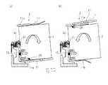
図2,3を参照して、液体吐出ヘッド2の構成について説明する。図2(a)は液体吐出ヘッドの分解斜視図、図2(b)は組み立て後の液体吐出ヘッドの斜視図、図3は図2(b)のA−A線に沿った液体吐出ヘッドの断面図である。液体吐出ヘッド2は、大別すると液体タンク装着部11と液体吐出部12とを有している。 The configuration of the
液体吐出部12は第1の液体を吐出する第1の吐出口4aを備える素子基板4と、装着された第1の液体タンク3aの第1の液体供給口13aを貫通し、第1の液体タンク3aの第1の液体を第1の吐出口4aに供給する第1の液体供給管14aとを有している。第1の液体供給管14aは第1の液体タンク3aの引き抜き方向Y2に直線状に延び、第1の液体タンク3aが装着されたときに第1の液体タンク3aの下部に位置する第1の液体供給口13aを貫通する。液体吐出部12は第1の液体に吐出するためのエネルギーを与えるエネルギー発生素子(図示せず)を有しており、エネルギー発生素子によって加熱された第1の液体が第1の吐出口4aから吐出する。液体吐出部12は装着された第1の液体タンク3aを引き抜き方向Y2へ付勢する弾性部材15を有している。本実施形態では、弾性部材15はコイルばねであり、第1の液体タンク3aの挿抜方向Yに伸縮可能である。液体吐出部12は、液体吐出装置1から信号や電力等を素子基板4に送るための複数の端子を備えるプリント基板である第1の電気配線基板39と、素子基板4と第1の電気配線基板39とを接続するフレキシブル配線基板40とを備える。さらに液体吐出部12は、液体タンク3aと液体吐出装置1との電気的な通信を行うための複数の端子を備えたプリント基板である第2の電気配線基板41を備える。後述するように、第1の液体タンク3aの電気基板31aは、液体吐出部12に設けられた電気接続部材32a、及び第2の電気配線基板41を介して液体吐出装置1の本体と電気的な通信を行う。このように液体吐出部12の同一面に第1の電気配線基板39と第2の電気配線基板41とを設けることで、夫々の電気配線基板のサイズ等を適正化することができ、1枚の電気配線基板で構成する場合に比べて電気配線基板を小型化することができる。また第2の電気配線基板41を装着面の全幅に渡って設けることで、装着面の強度を向上させることができる。 The
液体タンク装着部11は第1の液体を貯留する第1の液体タンク3aを収容する収容部を備える。液体タンク装着部11は上板11aと底板1bとこれらを連結する2つの側板11c,11dとを有する箱型の枠体形状を有している。上板11aと底板1bと側板11c,11dは、第1の液体タンク3aの挿入方向Y1における前方に位置する液体吐出部12とともに、第1の液体タンク3aの収容空間16aを形成している。液体タンク装着部11は固定手段18によって液体吐出部12に固定されている。本実施形態の固定手段18はねじ(ビス)である。ねじ18は、液体タンク装着部11に設けられた穴19を貫通し、液体吐出部12に設けられたねじ穴20と係合して、液体タンク装着部11を液体吐出部12に固定する。つまり、液体吐出ヘッド2を製造する際は、液体タンク装着部11と液体吐出部12を別部材として製作し、これらを固定手段18によって固定する。固定手段18はねじに限定されず、溶着、接着剤、嵌め合わせ(係合)などの任意の固定方法を用いることができる。 The liquid
液体タンク装着部11は装着された第1の液体タンク3aを固定するロック部材21を有している。ロック部材21は液体タンク装着部11の上板11aの上面に位置している。ロック部材21は、回転支点22の周りを回転可能な挿抜方向Yに細長い形状のレバー23と、第1の液体タンク3aの挿入方向Y1における後部に位置し、レバー23から斜め下方に延びる板ばね24と、を有している。第1の液体タンク3aの挿入方向Y1における前端、すなわちレバー23の回転支点22を挟んで板ばね24の反対側の端部には、レバー23の長手方向軸線25に対しほぼ直角かつ下方に延びる爪部26が形成されている。第1の液体タンク3aの上面38aは係止部である凹部28を備え、レバー23の爪部(係合部)26は凹部28と係合することができる。 The liquid
第1の液体タンク3aを装着する際は、液体タンク装着部11の底板1bに沿って第1の液体タンク3aを滑らせながら、第1の液体タンク3aを収容空間16aの内部に挿入する。板ばね24はレバー23と第1の液体タンク3aの間で圧縮されながらその先端が第1の液体タンク3aの上面38aを摺動する。レバー23は板ばね24の弾性復元力によって、図3において回転支点22の周りに反時計回りのモーメントを受け、レバー23の爪部26が第1の液体タンク3aの上面38aを摺動する。第1の液体タンク3aは弾性部材15と当接し、引き抜き方向Y2への付勢力を受ける。この弾性部材15の付勢力に抗してさらに第1の液体タンク3aを挿入し、第1の液体タンク3aが所定の装着位置に達すると、板ばね24の弾性復元力によってレバー23の爪部26が凹部28に係合し、第1の液体タンク3aは装着位置でロックされる。第1の液体タンク3aを取り外す際は、レバー23の挿入方向Y1における後端を押下げ、レバー23の爪部26と凹部28との係合を解除する。弾性部材15の付勢力によって第1の液体タンク3aが引き抜き方向Y2に押し出され、第1の液体タンク3aを液体タンク装着部11から容易に取り出すことができる。 When mounting the
液体吐出部12は、第1の液体タンク3aが液体タンク装着部11に装着されたときに第1の液体タンク3aの電気基板31aと電気接続する電気接続部材32aを有している。電気接続部材32aは鉛直方向Zにおいて爪部26と弾性部材15の間に位置している。電気接続部材32aの電気基板31aと電気接続する端部33aは引き抜き方向Y2に突き出しており、他端は電気配線基板34に接続されている。電気配線基板34は液体吐出装置本体の制御部(図示せず)に接続されている。電気基板31aと電気接続部材32aと電気配線基板34とを介して、第1の液体タンク3aの液体残量情報などが液体吐出装置本体の制御部に送信される。 The
液体吐出部12は、第1の液体タンク3aを装着する際に高精度に位置決めを行うため、第1の位置決めピン35aを有している。第1の位置決めピン35aは電気接続部材32aと第1の液体供給管14aの間に設けられており、第1の液体タンク3aの挿入方向Y1における前面から引き抜き方向Y2に延びる第1の位置決め穴36aと嵌合する。第1の位置決めピン35aと第1の位置決め穴36aの形状は円筒形であるが、第1の位置決めピン35aが第1の位置決め穴36aに嵌合する限りどのような形状でもかまわない。これにより第1の液体タンク3aの移動が規制され、電気接続部材32aと電気基板31aとの電気接続の信頼性を向上させることができる。以上の説明において、液体タンク装着部11には1つの第1の液体タンク3aを装着する構成について説明したが、本実施形態の液体タンク装着部11には複数の液体タンクが装着可能である。図2、3に示すように液体タンク装着部11には高さが実質的に等しい4つの液体タンクが装着可能となっている。このように液体タンク装着部11を箱型の枠体構成の筐体とし、その上面にロック部材21を設けることで、同様の着脱操作性を確保しつつ、複数個の液体タンクの着脱機構が可能となる。尚、本構成において、各液体タンクの高さは実質的に等しいほうが好ましいが、液体タンクの幅は適宜要求される使用に基づいて変更可能である。例えば、カラーインク用のタンクに比べてブラックインク用のタンクの幅を広くすることが可能である。弾性部材15と液体供給管14aは枠体内に設けられている。 The
液体吐出装置の仕様、用途に応じて異なる容量の液体タンクを装着可能とする場合がある。例えば、家庭用とビジネス用とでは印刷ボリュームが大きく異なるので、ビジネス用の液体タンクは家庭用に比べて大容量のインクを収納可能な大型の液体タンクの搭載が要求される。この場合、液体吐出部12は共通で適用な場合がある。尚、本発明によれば、異なる液体吐出装置への適用だけでなく、同じ1つの液体吐出装置に対しても、容量の異なる液体タンクが適用可能である。例えば、1つの液体装置に対して、2つの液体吐出ヘッド2を備え、一方の液体吐出ヘッドには比較的容量の小さい液体タンクを搭載し、他方の液体吐出ヘッドには比較的容量の大きい液体タンクを搭載する。また、1つの液体吐出ヘッドに対して、容量の異なる複数の液体タンクの搭載も可能である。例えばカラーインク用の液体タンクと、それに比較して高さの高い、ブラックインク用の液体タンクとを1つの液体吐出ヘッドに対して装着可能な構成も適用できる。
一例として、図1、3で説明した液体吐出装置とは異なる液体吐出装置(例えばビジネス用)に搭載される液体吐出ヘッド2の構成を図4に示す。図4は、第1の液体タンク3aよりも容量が大きい第2の液体タンク3bが装着された図3と同様の断面図である。本実施形態では第2の液体タンク3bの高さH2が第1の液体タンク3aの高さH1より高いが、第2の液体タンク3bの挿抜方向Yの奥行L2が第1の液体タンク3aの挿抜方向Yの奥行L1より長くてもよく、高さと奥行きの双方が異なっていてもよい。すなわち、第1の液体タンク3aと第2の液体タンク3bは高さと挿抜方向Yの奥行きの少なくともいずれかが異なっていればよい。このような液体タンクのセットを用いることにより、例えば、使用頻度の高い液体(ブラックのインクなど)を第2の液体タンクから供給し、それ以外の液体(カラーのインクなど)を第1、第3、第4の液体タンクから供給することができる。あるいは、液体吐出装置の機種や仕様に応じて液体タンクの容量を増減する場合は、機種や仕様に応じて、同じ種類の液体に対して第1の液体タンク3aと第2の液体タンク3bを選択的に使用することができる。尚、上述したように本発明は本実施形態のように容量が大きい液体タンクと容量の小さい液体タンクとの双方を1つの装置本体に装着可能な構成には限られない。例えば、比較的容量の小さい液体タンクが装着される比較的小型の装置と、比較的容量の大きい液体タンクが装着されるビジネス対応の比較的大型の装置とに対して、共通の液体吐出部12を適用することが可能である。双方の装置本体に対して、共通の構成の液体吐出部12を使用し、液体タンクの大きさに対応させた個別の液体タンク装着部11を適用すれば良い。Depending on the specifications and applications of the liquid ejection device, it may be possible to mount liquid tanks having different capacities. For example, since the printing volume differs greatly between home use and business use, the business liquid tank is required to be equipped with a large liquid tank capable of storing a large volume of ink as compared with the home use. In this case, the
As an example, FIG. 4 shows a configuration of a
本実施形態では、第1の液体タンク3aと第2の液体タンク3bの高さの違いに対処するため、図4に示す第2の液体タンク3bの収容空間16bの高さHH2が、図3に示す第1の液体タンク3aの収容空間16aの高さHH1より高くなっている。一方、第2の液体供給管14bは第1の液体供給管14aと同じ高さにある。すなわち、第2の液体タンク3bの底面37bと第2の液体供給管14b(中心軸)との間の高さ方向の距離h2は、第1の液体タンク3aの底面37aと第1の液体供給管14a(中心軸)との間の高さ方向の距離h1と等しい。同様に、第2の電気接続部材32bは第1の電気接続部材32aと同じ高さにある。すなわち、第2の液体タンク3bの底面37bと第2の電気接続部材32b(接触端部の中心位置)との間の高さ方向の距離k2は、第1の液体タンク3aの底面37aと第1の電気接続部材32a(接触端部の中心位置)との間の高さ方向の距離k1と等しい。さらに、第2の位置決めピン35bは第1の位置決めピン35aと同じ高さにある。すなわち、第2の液体タンク3bの底面37bと第2の位置決めピン35b(中心軸)との間の高さ方向の距離j2は、第1の液体タンク3aの底面37aと第1の位置決めピン35a(中心軸)との間の高さ方向の距離j1と等しい。 In this embodiment, in order to cope with the difference in height between the
これに対応して、第2の液体タンク3bの底面37bと第2の液体供給口13b(中心軸)との間の高さ方向の距離r2は、第1の液体タンク3aの底面37aと第1の液体供給口13a(中心軸)との間の高さ方向の距離r1と等しい。同様に、第2の液体タンク3bの底面37bと第2の電気基板31b(電気接続部材の接触中心)との間の高さ方向の距離s2は第1の液体タンク3aの底面37aと第1の電気基板31a(電気接続部材の接触中心)との間の高さ方向の距離s1と等しい。さらに、第2の液体タンク3bの底面37bと第2の位置決め穴36b(中心軸)との間の高さ方向の距離t2は第1の液体タンク3aの底面37aと第1の位置決め穴36a(中心軸)との間の高さ方向の距離t1と等しい。また図4に示すような比較的大容量の液体タンクを装着した状態において、鉛直方向に関して、弾性部材15と電気接続部32との間隔より、電気接続部32と爪部26との間隔のほうが大きい。このような構成により電気的な信頼性を確保しつつ、比較的大容量の液体タンク3bを適用することが可能となる。比較的小容量の液体タンクと、比較的大容量の液体タンクを適用した場合においても、電気的な信頼性や着脱信頼性を損ねることなく同一構成の液体吐出部12を共用することが可能となる。 Correspondingly, the distance r2 in the height direction between the
このように、第1の液体タンク3aと第2の液体タンク3bでは、容量や寸法に拘わらず、液体吐出部12との接続が生じる液体供給口13a,13b、電気基板31a,31b、位置決め穴36a,36bが同じ位置に設けられている。さらに、容量の異なる液体タンクを用いるときに構成の変更が生じる液体タンク装着部11は液体吐出部12とは別の部材として製作され、固定手段18によって液体吐出部12に固定されている。これらの方策によって、容量が異なる液体タンクを用いる場合でも、同一の構成の液体吐出部12を用いることができる。液体吐出部12は液体タンクの容量によって構成や大きさが変わらないため、キャリッジ5の大きさも同一にすることができる。このように液体供給管14aを備える液体吐出部12と、液体タンク装着部11とを別部材の構成とすることで、異なる容量や寸法の液体タンクに関しても、夫々の液体タンクに応じた液体吐出ヘッドを提供する必要はない。液体タンク装着部のみの変更で異なる容量や寸法の液体タンクに対して対応可能となる。 As described above, in the
本実施形態においては、液体吐出ヘッドの使用状態において、鉛直方向に関して下方から弾性部材15、電気接続部材32、爪部26がこの順に配置されている。図5を参照して、電気接続部材32を爪部26と弾性部材15の間に設け、ロック部材21を液体タンク装着部11の上板11aに設ける理由について説明する。図5(a)は比較例としての構成を説明する図で、液体タンク3のロック部材21が液体タンク装着部11の底板1bに位置する液体吐出ヘッドを示している。図5(b)は本実施形態のようにロック部材21が液体タンク装着部11の上板11aに位置する液体吐出ヘッドを示している。電気接続部材32は液体タンク3の液体残量情報などを液体吐出装置1の制御部に伝達するための接点である。電気接続部材32と液体タンク3の電気基板31との電気的接触が断たれると、液体タンク3が液体吐出ヘッド2に装着されていることが液体吐出装置1の制御部で認識できなくなり、液体吐出装置1の制御に影響を及ぼす。このため、電気接続部材32と電気基板31の接点信頼性は非常に重要である。 In the present embodiment, the
図5(a),(b)に示すいずれの液体吐出ヘッド2も、液体タンク3は弾性部材15によって引き抜き方向Y2に付勢されている。ロック部材21がこの付勢力を支持することによって、液体タンク3は液体タンク装着部11に固定されている。より詳細には、ロック部材21は装着された液体タンク3を弾性部材15の付勢力に抗して爪部26の周りで回動可能にロックしている。 In any of the liquid discharge heads 2 shown in FIGS. 5A and 5B, the
図5(a)に示す液体吐出ヘッド2では、液体タンク3は爪部26を支点すなわち回動中心として、図示の時計回りの方向、すなわち電気基板31が電気接続部材32から離れる方向に回転しようとする。このため、電気基板31と電気接続部材32との間の電気接点の信頼性が不安定となる。これは弾性部材15が爪部26と電気接続部材32の間にあるためである。特に、大容量の液体タンクを装着した場合は重心の位置が上がり、液体吐出ヘッド自体の姿勢も不安定となる。このため、主走査方向への移動中に電気接続部材32と電気基板31の電気的接触が一層不安定となる。 In the
これに対して図5(b)に示す液体吐出ヘッド2では、液体タンク3は爪部26を支点すなわち回動中心として、図示の反時計回りの方向、すなわち電気基板31が電気接続部材32に近づく方向に回転しようとする。電気基板31は電気接続部材32に強く押し付けられ、電気基板31と電気接続部材32との間の電気接点の信頼性が保たれる。これは電気接続部材32が爪部26と弾性部材15との間にあるためである。以上より、電気接続部材32は爪部26と弾性部材15の間に位置にあることが望ましく、本実施形態のように電気接続部材32が弾性部材15より上方にある場合には、ロック部材21は液体タンク3の上板11aに設けることが望ましい。 On the other hand, in the
爪部26の周りのモーメントは爪部26と弾性部材15の距離(アーム長)に依存する。従って、液体タンクの大容量化を行う際は液体タンクの高さ(Z方向寸法)を増加することが好ましいが、前述のように奥行(Y方向寸法)を増加することもできる。後者の場合でも電気基板31が電気接続部材32に近づく方向に回転するモーメントが発生するため、電気基板31と電気接続部材32との間の電気接点の信頼性は保たれる。 The moment around the
2 液体吐出ヘッド
3a 液体タンク
4a 吐出口
11 液体タンク装着部
12 液体吐出部
13a 液体供給管
18 固定手段2
Claims (11)
Translated fromJapanese前記素子基板に供給するための液体を貯留する液体タンクを収容する枠体形状の収容部と、前記液体タンクの係止部と係合する係合部を備えたロック部材と、を備える液体タンク装着部と、
前記液体吐出部と前記液体タンク装着部とを固定する固定手段と、
装着された前記液体タンクを離脱方向へ付勢する弾性部材と、
前記液体タンクが装着されたときに前記液体タンクに設けられた電気基板と電気接続する電気接続部材と、
を有し、
前記電気接続部材は前記ロック部材と前記弾性部材との間に位置する、液体吐出ヘッド。An element substrate including a discharge port for discharging liquid is connected to the contact point of the liquid discharge apparatus, a liquid ejecting portion and anelectrical wiring boardyou transmit a signal to the element substrate,
A liquid tank comprising: aframe-shaped housing portion that houses a liquid tank that stores liquid to be supplied to the element substrate; and a lock member that includes an engaging portion that engages with a locking portion of the liquid tank. A mounting part;
Fixing means for fixing the liquid ejection part and the liquid tank mounting part;
An elastic member for urging the mounted liquid tank in the disengagement direction;
An electrical connection member that is electrically connected to an electrical board provided in the liquid tank when the liquid tank is mounted;
I have a,
The liquid discharge head,wherein the electrical connection member is located between the lock member and the elastic member .
Priority Applications (2)
| Application Number | Priority Date | Filing Date | Title |
|---|---|---|---|
| JP2015059403AJP6494352B2 (en) | 2014-05-30 | 2015-03-23 | Liquid discharge head |
| US14/719,609US9446592B2 (en) | 2014-05-30 | 2015-05-22 | Liquid ejection cartridge and liquid ejection apparatus |
Applications Claiming Priority (3)
| Application Number | Priority Date | Filing Date | Title |
|---|---|---|---|
| JP2014112193 | 2014-05-30 | ||
| JP2014112193 | 2014-05-30 | ||
| JP2015059403AJP6494352B2 (en) | 2014-05-30 | 2015-03-23 | Liquid discharge head |
Publications (2)
| Publication Number | Publication Date |
|---|---|
| JP2016005887A JP2016005887A (en) | 2016-01-14 |
| JP6494352B2true JP6494352B2 (en) | 2019-04-03 |
Family
ID=54700768
Family Applications (1)
| Application Number | Title | Priority Date | Filing Date |
|---|---|---|---|
| JP2015059403AActiveJP6494352B2 (en) | 2014-05-30 | 2015-03-23 | Liquid discharge head |
Country Status (2)
| Country | Link |
|---|---|
| US (1) | US9446592B2 (en) |
| JP (1) | JP6494352B2 (en) |
Families Citing this family (7)
| Publication number | Priority date | Publication date | Assignee | Title |
|---|---|---|---|---|
| US10596815B2 (en) | 2017-04-21 | 2020-03-24 | Canon Kabushiki Kaisha | Liquid ejection head and inkjet printing apparatus |
| JP6953175B2 (en) | 2017-05-16 | 2021-10-27 | キヤノン株式会社 | Inkjet recording head and inkjet recording device |
| WO2018222194A1 (en)* | 2017-06-01 | 2018-12-06 | Hewlett-Packard Development Company, L.P. | Printhead carriages with mechanical protectors |
| JP7234696B2 (en)* | 2019-02-28 | 2023-03-08 | カシオ計算機株式会社 | Electronics and printers |
| JP2021024178A (en)* | 2019-08-02 | 2021-02-22 | セイコーエプソン株式会社 | Connection auxiliary tool, liquid supply device, and liquid jet device |
| KR20230158523A (en)* | 2021-03-19 | 2023-11-20 | 세이코 엡슨 가부시키가이샤 | cartridge |
| CN117042972A (en)* | 2021-03-19 | 2023-11-10 | 精工爱普生株式会社 | Box (B) |
Family Cites Families (19)
| Publication number | Priority date | Publication date | Assignee | Title |
|---|---|---|---|---|
| JPH02217257A (en)* | 1989-02-17 | 1990-08-30 | Canon Inc | Ink jet recording device |
| AU4092596A (en) | 1995-01-13 | 1996-08-08 | Canon Kabushiki Kaisha | Liquid ejecting head, liquid ejecting device and liquid ejecting method |
| TW312658B (en) | 1995-01-13 | 1997-08-11 | Canon Kk | |
| DE69733980T2 (en) | 1996-06-07 | 2006-02-23 | Canon K.K. | Method and device for ejecting liquid |
| JPH1024573A (en) | 1996-07-09 | 1998-01-27 | Canon Inc | Liquid discharge head, method of manufacturing the liquid discharge head, head cartridge, and liquid discharge device |
| JP3403009B2 (en) | 1996-07-12 | 2003-05-06 | キヤノン株式会社 | Liquid discharge method involving displacement of movable member and bubble growth, liquid discharge head used for the discharge method, head cartridge, and liquid discharge apparatus using these |
| US6027209A (en)* | 1997-09-03 | 2000-02-22 | Hewlett-Packard Company | Ordered storage and/or removal of inkjet cartridges and capping means from a storage container |
| US6491380B2 (en) | 1997-12-05 | 2002-12-10 | Canon Kabushiki Kaisha | Liquid discharging head with common ink chamber positioned over a movable member |
| JPH11320914A (en)* | 1998-05-13 | 1999-11-24 | Seiko Epson Corp | Ink jet recording device |
| EP2179848A1 (en)* | 1998-05-18 | 2010-04-28 | Seiko Epson Corporation | Ink-jet printing apparatus and ink cartridge therefor |
| MXPA04012681A (en)* | 2003-12-26 | 2005-07-01 | Canon Kk | Liquid container and liquid supplying system. |
| JP2006110837A (en)* | 2004-10-14 | 2006-04-27 | Canon Inc | Inkjet recording head cartridge |
| JP4933161B2 (en)* | 2006-06-08 | 2012-05-16 | キヤノン株式会社 | Image heating device |
| JP5213328B2 (en) | 2006-12-13 | 2013-06-19 | キヤノン株式会社 | Recording head, head cartridge, and recording apparatus |
| JP5541655B2 (en) | 2008-06-17 | 2014-07-09 | キヤノン株式会社 | Recording head |
| JP5541656B2 (en) | 2008-06-17 | 2014-07-09 | キヤノン株式会社 | Recording head |
| ES2752226T3 (en) | 2010-10-22 | 2020-04-03 | Hewlett Packard Development Co | Fluid cartridge |
| JP6137918B2 (en) | 2013-04-12 | 2017-05-31 | キヤノン株式会社 | Inkjet recording head and inkjet recording apparatus |
| JP6312507B2 (en) | 2013-05-13 | 2018-04-18 | キヤノン株式会社 | Liquid ejection device and liquid ejection head |
- 2015
- 2015-03-23JPJP2015059403Apatent/JP6494352B2/enactiveActive
- 2015-05-22USUS14/719,609patent/US9446592B2/enactiveActive
Also Published As
| Publication number | Publication date |
|---|---|
| US20150343770A1 (en) | 2015-12-03 |
| US9446592B2 (en) | 2016-09-20 |
| JP2016005887A (en) | 2016-01-14 |
Similar Documents
| Publication | Publication Date | Title |
|---|---|---|
| JP6494352B2 (en) | Liquid discharge head | |
| CN103203996B (en) | Box and printing equipment | |
| TWI637859B (en) | Carcass and printing material supply system | |
| JP5119719B2 (en) | Liquid container | |
| US10434786B2 (en) | Liquid supply unit | |
| JP3667284B2 (en) | Liquid storage container and recording apparatus | |
| CN107718892A (en) | Container, liquid injection apparatus, liquid accommodating body | |
| JP6183273B2 (en) | cartridge | |
| US9132649B2 (en) | Removable guide element | |
| JP6079362B2 (en) | Printing fluid supply apparatus and printing fluid cartridge | |
| US7954937B2 (en) | Ink jet printing apparatus | |
| JP5007635B2 (en) | Liquid detection unit, liquid storage container using the same, and liquid storage container manufacturing method and decomposition method | |
| JP5927954B2 (en) | Cartridge and printing apparatus | |
| JP6202052B2 (en) | Liquid supply unit | |
| US8231192B2 (en) | Liquid detection unit, and liquid container using liquid detection unit | |
| US7735985B2 (en) | Cartridge holder | |
| JP4579813B2 (en) | Liquid jet recording device | |
| CN104512105B (en) | Printing unit that can be shared with general inkjet printing and page width printing | |
| CN105196702B (en) | Unit and fluid jet recording apparatus for fluid jet recording apparatus | |
| JP6372322B2 (en) | Liquid container and cartridge | |
| JP2013086338A (en) | Ink cartridge, ink jet printer and method of manufacturing ink cartridge | |
| KR200463175Y1 (en) | Apparatus for supplying ink of printer | |
| JP2000218822A (en) | Ink jet recording apparatus | |
| JP2017191847A (en) | Circuit board, liquid container holder, and liquid consuming device |
Legal Events
| Date | Code | Title | Description |
|---|---|---|---|
| A621 | Written request for application examination | Free format text:JAPANESE INTERMEDIATE CODE: A621 Effective date:20171218 | |
| A131 | Notification of reasons for refusal | Free format text:JAPANESE INTERMEDIATE CODE: A131 Effective date:20181002 | |
| A977 | Report on retrieval | Free format text:JAPANESE INTERMEDIATE CODE: A971007 Effective date:20180928 | |
| A521 | Request for written amendment filed | Free format text:JAPANESE INTERMEDIATE CODE: A523 Effective date:20181116 | |
| TRDD | Decision of grant or rejection written | ||
| A01 | Written decision to grant a patent or to grant a registration (utility model) | Free format text:JAPANESE INTERMEDIATE CODE: A01 Effective date:20190205 | |
| A61 | First payment of annual fees (during grant procedure) | Free format text:JAPANESE INTERMEDIATE CODE: A61 Effective date:20190305 | |
| R151 | Written notification of patent or utility model registration | Ref document number:6494352 Country of ref document:JP Free format text:JAPANESE INTERMEDIATE CODE: R151 |