JP6491275B2 - Vibration generator - Google Patents
Vibration generatorDownload PDFInfo
- Publication number
- JP6491275B2 JP6491275B2JP2017140502AJP2017140502AJP6491275B2JP 6491275 B2JP6491275 B2JP 6491275B2JP 2017140502 AJP2017140502 AJP 2017140502AJP 2017140502 AJP2017140502 AJP 2017140502AJP 6491275 B2JP6491275 B2JP 6491275B2
- Authority
- JP
- Japan
- Prior art keywords
- joint
- vibration generator
- outer peripheral
- bottom plate
- weight
- Prior art date
- Legal status (The legal status is an assumption and is not a legal conclusion. Google has not performed a legal analysis and makes no representation as to the accuracy of the status listed.)
- Active
Links
Images


Landscapes
- Apparatuses For Generation Of Mechanical Vibrations (AREA)
Description
Translated fromJapaneseこの発明は、振動発生器に関し、特に、往復移動して振動を発生させる振動発生器に関する。 The present invention relates to a vibration generator, and more particularly to a vibration generator that reciprocates to generate vibration.
振動子を運動させて振動を発生させる振動発生器としては、例えば、マグネットを含む振動子を、磁力を用いて往復運動させるものがある。 As a vibration generator that generates vibration by moving a vibrator, for example, there is a vibrator that reciprocates a vibrator including a magnet using a magnetic force.
下記特許文献1には、固定部である枠部の内部に可動部となる磁石を配置し、磁石と枠部との間に板ばねを設けて磁石を保持した構造のリニアモータが開示されている。このリニアモータにおいて、磁石は、磁石の上下を挟むように配置されたコイル部が励磁することで、枠部に対して移動する。 The following
ところで、上記の特許文献1に記載されているような振動発生器は、板ばねにより磁石を付勢して磁石を移動させるものであるため、板ばねが変形するスペースを比較的広く確保することが必要である。そのため、振動発生器に対する振動子の大きさを大きくするのには限界があり、振動量を大きくするのは困難である。 By the way, since the vibration generator as described in the above-mentioned
この発明は、揺動部の揺動時にウエイトに対して弾性部材がずれにくくなる振動発生器を提供することを目的としている。An object of the present invention is to provide a vibration generator in which theelastic member is less likely to be displaced with respect to the weight when theswinging portion swings .
上記目的を達成するためこの発明のある局面に従うと、振動発生器は、ボトムプレートと、トッププレートと、ボトムプレートとトッププレートとの間に配置されたフレームと、揺動部と、フレームに対して揺動部を水平方向に変位可能に支持する弾性部材と、を備え、揺動部は、弾性部材に接合される第1の接合部を有するウエイトを備え、ウエイトのフレームに対向する外周面の一部分は、第1の接合部を構成し、弾性部材は、ウエイトに接合される第2の接合部を備え、第1の接合部の外周面の一部分と第2の接合部の外周面の一部分とが、接合面を構成しており、トッププレートに対向するウエイトの面とボトムプレートに対向するウエイトの面との間において、接合面を構成する第1の接合部の外周面の一部分又は接合面を構成する第2の接合部の外周面の一部分には、傾斜を有する起伏があり、水平方向において、トッププレートに対向する第1の接合部の面及びトッププレートに対向する第2の接合部の面は並んで配置されており、水平方向において、ボトムプレートに対向する第1の接合部の面及びボトムプレートに対向する第2の接合部の面は並んで配置されている。According to one aspect of the present invention for achieving the above object, avibration generator is provided for a bottom plate, a top plate, a framedisposed between the bottom plate and the top plate , a swinging portion, and theframe. and an elasticmember for displaceably supporting the swing unit horizontally Te, swinging unit includes a weighthaving a first joint portion joined to the elastic member,the outer peripheral surface facing the frame of the weight The elastic member has a second joint portion joined to the weight, and a part of the outer peripheral surface of the first joint portion and the outer peripheral surface of the second joint portion. A part of the outer peripheral surface of the first joint part constituting the joint surface between the surface of the weight facing the top plate and the surface of the weight facing the bottom plate, or Configure the joint surface A portion of the outer peripheral surface of the second joint has an undulation having an inclination, and in the horizontal direction, the surface of the first joint facing the top plate and the surface of the second joint facing the top plate are In the horizontal direction, the surface of the first joint portion facing the bottom plate and the surface of the second joint portion facing the bottom plate are disposed side by side in the horizontal direction .
好ましくは、弾性部材は、梁部を備え、トッププレートからボトムプレートに向かう方向における梁部の寸法は、揺動部の揺動方向における梁部の寸法よりも大きい。Preferably, theelastic member includes a beam portion, and the size of the beam portion in the direction from the top plate to the bottom plate is larger than the size of the beam portion in the swing direction of the swing portion.
好ましくは、弾性部材を含む複数の弾性部材を備え、ウエイトは、複数の第1の接合部を有し、複数の弾性部材それぞれの第2の接合部の外周面の一部分と複数の第1の接合部それぞれの外周面の一部分とが、接合面を構成している。
好ましくは、トッププレートに対向するウエイトの面とボトムプレートに対向するウエイトの面との間において、接合面を構成する第1の接合部の外周面の一部分のみが起伏を有する。
好ましくは、トッププレートからボトムプレートに向かう方向において、傾斜を有する起伏は傾斜している。
好ましくは、接合面を構成する第1の接合部の外周面の一部分内及び接合面を構成する第2の接合部の外周面の一部分内に起伏がある。
好ましくは、トッププレートに対向する第1の接合部の面に溝部が設けられており、溝部は接合面を構成している。
好ましくは、ボトムプレートに対向する第1の接合部の面に溝部が設けられており、溝部は接合面を構成している。Preferably, the weight includes a plurality of elastic members including an elastic member, the weight includes a plurality of first joint portions, a part of the outer peripheral surface of each of the second joint portions of the plurality of elastic members, and the plurality of first portions. A part of the outer peripheral surface of each joint portion constitutes a joint surface.
Preferably, only a part of the outer peripheral surface of the first joint portion constituting the joint surface has undulations between the weight surface facing the top plate and the weight surface facing the bottom plate.
Preferably, the undulation having an inclination is inclined in a direction from the top plate to the bottom plate.
Preferably, there are undulations in a part of the outer peripheral surface of the first joint part constituting the joint surface and in a part of the outer peripheral surface of the second joint part constituting the joint surface.
Preferably, the groove part is provided in the surface of the 1st junction part which opposes a top plate, and the groove part comprises the junction surface.
Preferably, the groove part is provided in the surface of the 1st junction part which opposes a bottom plate, and the groove part comprises the junction surface.
好ましくは、溝部は揺動部の揺動方向とは異なる方向に形成されている。
好ましくは、接合面は平面である部分を含む。
好ましくは、接合面を構成する第1の接合部の外周面の一部分と接合面を構成する第2の接合部の外周面の一部分とは、貼り付いている。
好ましくは、傾斜を有する起伏は、突出部を有する。
好ましくは、箱形の外形を有する筐体を備え、筐体は、トッププレートとボトムプレートとフレームとで形成される。Preferably, the groove portion is formed in a direction different from the swing direction of the swing portion.
Preferably, the joining surface includes a portion that is a flat surface.
Preferably, a part of the outer peripheral surface of the first joint part constituting the joint surface and a part of the outer peripheral surface of the second joint part constituting the joint surface are adhered.
Preferably, the sloped undulation has a protrusion.
Preferably, a housing having a box shape is provided, and the housing is formed of a top plate, a bottom plate, and a frame.
以下、本発明の実施の形態の1つにおける振動発生器について説明する。 Hereinafter, a vibration generator in one embodiment of the present invention will be described.
振動発生器は、振動子のうちマグネットを保持する部分が、振動発生器の他の部分に対して変位可能に支持された構造を有している。マグネットの近くには、マグネットから離れて、コイルが配置されている。コイルは、マグネットの位置及び姿勢のうち少なくとも一方を変化させるための磁場を発生させる。振動発生器は、コイルの励磁に応じて振動子が変形してマグネットが往復運動することで、振動力を発生する。すなわち、振動発生器は、いわゆるリニアタイプのものである。 The vibration generator has a structure in which a portion of the vibrator that holds the magnet is supported so as to be displaceable with respect to the other portions of the vibration generator. A coil is arranged near the magnet, away from the magnet. The coil generates a magnetic field for changing at least one of the position and posture of the magnet. The vibration generator generates a vibration force by deforming the vibrator according to the excitation of the coil and causing the magnet to reciprocate. That is, the vibration generator is of a so-called linear type.
[第1の実施の形態] [First Embodiment]
図1は、本発明の実施の形態の1つにおける振動発生器を示す平面図である。図2は、図1のA−A線断面図である。図3は、振動発生器の構造を示す斜視図である。 FIG. 1 is a plan view showing a vibration generator in one embodiment of the present invention. 2 is a cross-sectional view taken along line AA in FIG. FIG. 3 is a perspective view showing the structure of the vibration generator.
図1においては、振動発生器1の部品レイアウトが容易に理解できるように、本来トッププレート20によって隠れている振動子50などが、部分的に実線で表示されている。図1においては、フレキシブルプリント基板(FPC;以下、単に基板ということがある。)10の図示は、一部を除き省略されている。 In FIG. 1, the
以下の説明において、振動発生器1について、図1で示される座標のX軸方向を左右方向(原点から見てX軸で正となる方向が右方向)、Y軸方向を前後方向(原点から見てY軸で正となる方向が後方向)ということがある。また、図2のZ軸方向(図1のXY平面に垂直な方向)を上下方向(原点から見てZ軸で正となる方向が上方向)ということがある。 In the following description, with respect to the
[振動発生器1の全体構造] [Overall structure of vibration generator 1]
図3に示されるように、振動発生器1は、大まかに、基板10と、トッププレート20と、ボトムプレート30と、コイル40と、振動子50とを有している。図1に示されるように、振動子50は、本実施の形態において、フレーム55と、揺動部60と、4つのアーム部(弾性部材の一例)80(80a,80b,80c,80d)とを有している。 As shown in FIG. 3, the
後述するように、振動発生器1は、揺動部60が、フレーム55など振動子50を含む振動発生器1の他の部位に対して主に左右方向に変位し、揺動することで、振動を発生させる。すなわち、本実施の形態において、揺動部60の揺動方向は、左右方向である。 As will be described later, in the
振動発生器1は、全体として、上下の寸法が比較的小さい薄型の略直方体形状に形成されている。振動発生器1は、例えば、左右方向、前後方向のそれぞれの外形寸法が10ミリメートル〜20ミリメートル程度しかない、小型のものである。振動発生器1は、側周を囲むフレーム55を有する振動子50の上面と下面とがトッププレート20とボトムプレート30とで覆われた、箱形の外形を有している。 The
図3に示されるように、振動子50は、フレーム55の内側に、揺動部60が配置された構造を有している。フレーム55と揺動部60とは、4つのアーム部80を介して接続されている。 As shown in FIG. 3, the
本実施の形態において、フレーム55は、例えば、1つ又は複数の、帯状の金属板などを折り曲げることで、長方形の環状に形成されている。換言すると、フレーム55は、四角型で中空に形成された筒形状を有しており、その内部に、揺動部60が配置されている。なお、フレーム55は、完全な環状でなくてもよい。例えば、部分的に途切れているものであったり、1つ又は複数の金属板の端部同士が部分的に重なるようにして全体として環状に形成されたものであったりしてもよい。 In the present embodiment, the
揺動部60は、平面視で、略長方形状に形成されている。揺動部60は、水平面(図1においてXY平面)に平行となる板形状を有している。揺動部60は、平面視で、四角を除き、各辺が前後方向又は左右方向に対して平行な略長方形形状に形成されている。 The
揺動部60は、平面視で振動子50の中央部、すなわち振動発生器1の中央部に配置されている。図2に示されるように、揺動部60は、コイル40と略平行に、コイル40に対して面対向に配置されている。 The oscillating
トッププレート20は、平板状であり、フレーム55の上端縁と略同型状の、長方形形状を有している。トッププレート20は、フレーム55の上端部にはめ込まれるようにして配置されている。ボトムプレート30は、平板状であり、フレーム55の下端縁と略同型状の、長方形形状を有している。トッププレート20は、フレーム55の下端部にはめ込まれるようにして配置されている。トッププレート20やボトムプレート30は、フレーム55に接着されていたり、溶接されていたりしてもよい。 The
本実施の形態においては、ボトムプレート30の短辺の一部に、切り欠き部35が形成されている。切り欠き部35が形成されていることにより、振動発生器1の内部と外部とは、連通している。 In the present embodiment, a
図2に示されるように、基板10は、コイル40へ接続される電極が形成された第1の部分10aと、振動発生器1を駆動させるためのラインが接続される電極が形成された第2の部分10bとが、折り曲げ部10cを介して互いに繋がっているものである。折り曲げ部10cは、切り欠き部35を通る幅に形成されている。基板10は、切り欠き部35に折り曲げ部10cが位置するようにし、第1の部分10aと第2の部分10bとでボトムプレート30を上下に挟むようにして配置されている。このようなフレキシブルプリント基板10が用いられていることで、両面基板を用いる場合と比較して、振動発生器1の上下方向の寸法を削減できる。また、単純な形状のボトムプレート30を用いることができるので、振動発生器1の製造コストを低減できる。ボトムプレート30には切り欠き部35が設けられているので、基板10が筐体外側にはみ出すことがなく、基板10を確実に保護することができる。 As shown in FIG. 2, the
コイル40は、例えば導線を巻回してなる、全体として楕円形で平板状の空芯コイルである。すなわち、コイル40は、巻回軸方向の寸法が、巻回軸方向に直交する方向の寸法よりも小さい薄型コイルである。なお、コイル40は、金属箔を巻回したものをスライスしてなるものであったり、シートコイルを積層したものであったりしてもよい。また、コイル40は、平面視で、円形や、四角形形状などの多角形形状を有していてもよい。 The
コイル40は、巻回軸方向が上下方向となるようにして、基板10の第1の部分10a上に配置されている。図1に示されるように、コイル40は、平面視で、振動発生器1の中央部に、後述するように揺動部60に対して面対向に配置されている。コイル40は、基板10の第1の部分10a上に形成されている電極(図示せず)に接続されている。振動発生器1の外表面に露出する、基板10の第2の部分10bに形成されている電極(図示せず)に通電することで、コイル40に通電することができる。 The
このように、揺動部60及びコイル40は、トッププレート20、ボトムプレート30、及びフレーム55により覆われている。これにより、振動発生器1の内部にちりなどの異物が入ることを防止することができ、振動発生器1を動作可能に保つことができる。また、振動発生器1は、トッププレート20、ボトムプレート30、及びフレーム55で箱形に囲まれているので、振動発生器1自身の剛性が高くなる。したがって、振動発生器1は、確実に振動を発生することができる。また、振動発生器1は、外部機器等への取り付け作業時において取り扱いやすいものとなる。 As described above, the swinging
本実施の形態において、フレーム55及びトッププレート20は、例えば鉄などの軟磁性体製である。振動発生器1は、フレーム55及びトッププレート20で囲まれた構造を有するので、周囲の磁場等に影響されにくい。また、振動発生器1内の磁束が外部に漏れにくく、外部の機器や回路などに影響が及ぶことが防止される。 In the present embodiment, the
他方、ボトムプレート30は、非磁性材料を用いて構成されている。ボトムプレート30は、例えば非磁性ステンレス鋼など、非磁性の金属材料を用いて構成されている。なお、ボトムプレート30は、金属材料を用いたものに限られず、例えば樹脂製であってもよい。また、フレーム55やトッププレート20は、軟磁性体製に限られず、例えば樹脂や非磁性の金属材料を用いて構成されていてもよい。 On the other hand, the
[振動子50の詳細構造] [Detailed structure of vibrator 50]
図2に示されるように、揺動部60は、マグネット61と、バックヨーク63と、ウエイト65とを有している。マグネット61は、永久磁石であり、揺動部60の略中央に配置されている。バックヨーク63は、例えば鉄などの軟磁性体であり、マグネット61の上部に配置されている。ウエイト65は、マグネット61及びバックヨーク63の周囲に、マグネット61及びバックヨーク63を保持するようにして配置されている。ウエイト65は、例えば、比重が比較的大きい金属などで構成されている。 As shown in FIG. 2, the swinging
本実施の形態において、マグネット61としては、左右に分かれて配置された2つ(マグネット61a,61b)が設けられている。マグネット61aと、マグネット61bとは、互いに極性が異なるように構成されている。すなわち、マグネット61aのコイル40に対する磁極の向きは、マグネット61bのそれと反対である。なお、マグネット61としては、コイル40に対する磁極の向きが左右で互いに異なるように着磁された1つが設けられていてもよい。例えば、マグネット61は、コイル40に対向する底面側部分において、N極とS極とが左右方向に分かれるように2極に着磁されているものであってもよい。また、3つ以上のマグネット61が配置されていてもよい。 In the present embodiment, as the
図1に示されるように、各アーム部80は、揺動部60のうちウエイト65の外周面に接合されているウエイト接合部81と、フレーム55の内側面に接合されているフレーム接合部83と、ウエイト接合部81とフレーム接合部83との間を接続する梁部85と、ウエイト接合部81側に形成されたゲート部87とを有している。各アーム部80は、例えば、弾性を有する樹脂で一体に成形されている。 As shown in FIG. 1, each
梁部85は、各アーム部80のうち、フレーム55に対して揺動部60が変位するときに主としてたわむ部位である。各アーム部80は、それぞれの梁部85の長手方向がY軸方向に略平行となるようにして配置されている。すなわち、梁部85は、揺動部60の揺動方向に対して垂直な方向が長手方向となるように、形成されている。 The
本実施の形態において、梁部85の長手方向に対して垂直な断面(すなわち、ZX平面に平行な断面;以下、単に梁部85の断面ということがある)は、長方形である。その断面の短辺は、揺動部60の揺動方向に対して略平行となっている。 In the present embodiment, a cross section perpendicular to the longitudinal direction of the beam portion 85 (that is, a cross section parallel to the ZX plane; hereinafter, simply referred to as a cross section of the beam portion 85) is a rectangle. The short side of the cross section is substantially parallel to the swinging direction of the swinging
4つのアーム部80は、揺動部60がフレーム55に対してバランス良く支持されるように、揺動部60の4つの角(右後、右前、左前、左後)に接続されている。アーム部80aは、ウエイト65の右後に配置されている。アーム部80bは、ウエイト65の右前に配置されている。アーム部80cは、ウエイト65の左前に配置されている。アーム部80dは、ウエイト65の左後に配置されている。 The four
揺動部60は、平面視で揺動部60の中心を通りYZ平面に平行な第1の平面及び揺動部60の中心を通りZX平面に平行な第2の平面のそれぞれについて、対称な形状を有している。また、4つのアーム部80は、上記第1の平面及び第2の平面のそれぞれについて、対称となる位置に、対称となる姿勢で配置されている。すなわち、振動子50は、上記第1の平面及び第2の平面のそれぞれについて対称に構成されている。 The oscillating
ここで、図1に示されるように、ウエイト65のうちアーム部80が配置されているそれぞれの部位(ウエイト65とアーム部80との接合部)には、溝部67(67a,67b,67c,67d)が形成されている。 Here, as shown in FIG. 1, each portion of the
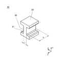
図4は、ウエイト65のうち溝部67が形成されている部位を示す斜視図である。 FIG. 4 is a perspective view showing a portion of the
図4を参照して、溝部67は、揺動部60の揺動方向(ここでは、主としてX軸方向)に対して平行とはならない方向が長手方向となるように形成されている。すなわち、溝部67は、揺動部60の揺動方向に対して略垂直なZ軸方向が長手方向となるようにして形成されている。 Referring to FIG. 4, groove 67 is formed such that the longitudinal direction is a direction that is not parallel to the swinging direction of swinging unit 60 (here, mainly the X-axis direction). That is, the
このように溝部67が形成されているのに対し、アーム部80には、溝部67に食い込むようにウエイト接合部81から突出するゲート部87が形成されている。すなわち、アーム部80とウエイト65との接合面は、揺動部60の揺動方向に対して垂直な方向に起伏している。 While the
[振動子50の製造方法についての説明] [Description on Manufacturing Method of Vibrator 50]
本実施の形態において、振動子50は、フレーム55、揺動部60(マグネット61、バックヨーク63、及びウエイト65)、及び4つのアーム部80が、インサート成形により一体成形されて構成されている。振動子50の製造は、次のようにして行われる。 In the present embodiment, the
まず、ウエイト65にバックヨーク63とマグネット61とが貼り付けられる。これにより揺動部60が構成される。また、長方形形状に折り曲げた状態のフレーム55を用意する。バックヨーク63とマグネット61とは、例えばスポット溶接や接着により、互いに貼り付けられればよい。 First, the
次に、振動子50の成形型に、フレーム55と、揺動部60とがセットされる。 Next, the
そして、成形型に、アーム部80を構成する樹脂を流し込む。成形型を外すことで、振動子50が得られる。 Then, a resin constituting the
なお、バックヨーク63やマグネット61は、一体成形が行われた後で、ウエイト65部分に貼り付けられていてもよい。 Note that the
アーム部80などに用いられる樹脂(一体成形に用いられる樹脂)としては、例えば、シリコン樹脂などが用いられる。そのほか、熱に強いフッ素系のゴムなどを用いてもよい。このようなゴムを用いて振動子50を形成することにより、振動発生器1の耐熱性を向上させることができる。弾性体はこれに限られず、種々のものを用いることができる。 As a resin (resin used for integral molding) used for the
ここで、上述のようにウエイト65に溝部67が形成されているところ、振動子50の一体成形に際しては、溝部67をゲートとして用いて樹脂の注入が行われる。したがって、より容易に、成形を行うことができる。 Here, when the
[振動発生器1の動作の説明] [Description of Operation of Vibration Generator 1]
振動発生器1において、揺動部60は、アーム部80の梁部85を変形させながら、フレーム55に対して変位可能である。コイル40は、揺動部60をフレーム55に対して往復運動させるための磁場を発生する。コイル40が励磁されると、それに伴って、揺動部60がフレーム55に対して変位する。振動発生器1は、揺動部60の往復運動が繰り返されることで、振動を発生させる。 In the
より具体的には、コイル40に電流が流れると、コイル40が励磁し、上下方向に磁場が生じる。磁場が生じると、マグネット61がこの磁場の影響を受け、反発・吸引の力が生じる。揺動部60には、磁場の方向及びマグネット61の磁極の配置に応じて、左方又は右方へ変位させる力が作用する。そのため、揺動部60は、各梁部85をたわませながら、左右方向のいずれかに変位する。コイル40に交流が流されることにより、その交流に応じて、揺動部60は、平面視で、フレーム55に対して、左右方向に往復直線運動を行う。これにより、振動発生器1が振動力を発生する。 More specifically, when a current flows through the
交流の電流値が小さくなり、磁場が弱くなったり磁場がなくなったりすると、揺動部60は、アーム部80の復元力により、平面視で振動発生器1の中央部に戻ろうとする。このとき、アーム部80は弾性体であるところ、アーム部80で消費されるエネルギは比較的大きくなる。したがって、振動は速やかに減衰される。 When the alternating current value decreases and the magnetic field becomes weaker or disappears, the oscillating
本実施の形態において、ボトムプレート30は非磁性材料を用いて構成されているので、揺動部60とボトムプレート30との間に、マグネット61による磁気吸引力は発生しない。揺動部60は、コイル40が発生させた磁場に応じて、スムーズに、効率良く変位する。したがって、振動発生器1を、より薄型化でき、かつ、適正に動作させることができる。 In the present embodiment, since the
[梁部85の形状の説明] [Description of shape of beam portion 85]
ここで、本実施の形態において、各アーム部80の梁部85の形状は、次のように、振動子50が効率良く動作するように決定されている。 Here, in the present embodiment, the shape of the
図5は、アーム部80を示す斜視図である。 FIG. 5 is a perspective view showing the
図5に示されるように、本実施の形態において、梁部85の縦方向の寸法(梁部85の断面の長辺の寸法)hは、梁部85の横方向の寸法(梁部85の断面の短辺の寸法)tよりも、大きくなっている。例えば、縦方向の寸法hは、横方向の寸法tの2倍程度の大きさになっている。 As shown in FIG. 5, in the present embodiment, the vertical dimension (the dimension of the long side of the cross section of the beam part 85) h of the
このように梁部85の形状が設定されていることにより、揺動部60のZ軸方向に対する挙動が比較的抑えられる一方で、振動量が大きく得られる。したがって、コイル40が励磁されることにより発生する力を、効率良く、揺動部60の主となる揺動方向に伝達させることができる。なお、梁部85の縦方向の寸法hと横方向の寸法tとの最適な寸法比は、それらのパラメータを変更しながらシミュレーションを行うことなどにより、適宜求めることができる。 By setting the shape of the
[実施の形態における効果] [Effects of the embodiment]
以上説明したように、本実施の形態においては、振動子50が、フレーム55と、揺動部60と、アーム部80とが一体成形されて構成されている。したがって、振動子50を、容易に、かつ、高い組立精度で組み立てることができる。揺動部60をフレーム55に取り付ける手間も掛からず、部品点数も少なく抑えられるので、振動発生器1の製造コストを低減できる。また、揺動部60及びフレーム55は一体に形成されているので、揺動部60とフレーム55との取り付け部は、もろくなることはない。したがって、振動発生器1の衝撃に対する信頼性を高めることができる。揺動部60のフレーム55への取り付けに、ねじなどの別の部材を要することがないので、振動発生器1の小型化、薄型化、軽量化を進めることができる。 As described above, in the present embodiment, the
本実施の形態では、揺動部60とフレーム55とは、別部材で構成されているので、部品点数が少なくなる。また、容易に組立て可能な簡素な構造としながら、フレーム55の材質を適宜選択できる。したがって、例えば別途磁気シールドとして機能する部材などを設けることなく、フレーム55がその役割を果たすように構成することができる。 In the present embodiment, since the swinging
振動子50は、フレーム55も含めて一体成形されている。したがって、アーム部80の大きさを、比較的、小さくしたまま、十分な振動力を得ることができる。振動子50の全体の大きさに比して、すなわち振動発生器1の全体の大きさに比して、揺動部60の大きさを、比較的大きくすることができる。そのため、小型の振動発生器1においても、比較的大きな振動量を得ることができる。特に、各アーム部80において、梁部85の長手方向は、揺動方向に直交する方向であり、梁部85は揺動方向に効率良く変形する。したがって、本効果をより効果的に得ることができる。 The
アーム部80は、上記第1の平面及び第2の平面のそれぞれについて対称となるように配置されている。したがって、揺動部60がバランス良く支持され、振動発生器1は、振動をより効果的に発生させることができる。 The
アーム部80とウエイト65との接合部は、溝部67が設けられていることで、起伏している。特に、溝部67は、揺動部60の揺動方向とは異なる方向が長手方向となるように形成されている。溝部67が設けられていなくても、アーム部80と揺動部60との接合強度は十分に得られるが、このように溝部67を設けることで、アーム部80に対して揺動方向に揺動部60がずれるなどのトラブルを、より確実に防止でき、振動発生器1の耐久性をより向上させることができる。 The joint portion between the
[変型例の説明] [Description of variant]
振動子は、アーム部の梁部にスリットを有していてもよい。 The vibrator may have a slit in the beam portion of the arm portion.
図6は、本実施の形態の一変型例に係る振動発生器を示す平面図である。 FIG. 6 is a plan view showing a vibration generator according to a variation of the present embodiment.
図6においては、振動発生器101は、図1と同様にして示されている。振動発生器101は、上述の振動発生器1と比較して、アーム部80とは形状がやや異なるアーム部180(180a,180b,180c,180d)を有している点で相違する。なお、図6において、溝部67の図示は省略されている。アーム部80とアーム部180との違いのほかは、振動発生器101は、振動発生器1と略同一の構成を有している。 In FIG. 6, the
図7は、アーム部180を示す斜視図である。 FIG. 7 is a perspective view showing the
図7に示されるように、アーム部180は、アーム部80の梁部85と比べてX軸方向の幅が広い梁部185を有している。梁部185は、そのX軸方向中央部に、梁部185の長手方向に沿って形成されたスリット186を有している。スリット186は、梁部185の上面から下面まで貫通するように形成されている。スリット186は、ウエイト接合部81からフレーム接合部83までの間の全域に形成されている。すなわち、梁部185は、スリット186が形成されていることで、X軸方向の幅が狭い2本の梁に分かれている。梁部185のX軸方向の幅寸法やスリット186の幅寸法などは、振動子50の振動時における振幅量などの特性が所望のものになるように、適宜設定されていればよい。 As shown in FIG. 7, the
このように梁部185にスリット186が設けられていることにより、揺動部60が変位するときに梁部185に生じる応力は、スリット186が設けられていないタイプの梁部85を用いた場合と比較して低減する。したがって、梁部185の寿命を比較的長くすることができ、振動発生器101の耐久性をより向上させることができる。 Since the
溝部は、ウエイトとアーム部との接合部のうち一部にのみ設けられていてもよい。 The groove part may be provided only in a part of the joint part between the weight and the arm part.
図8は、本実施の形態の別の変型例に係る振動発生器のウエイトのうち、溝部が形成されている部位を示す斜視図である。 FIG. 8 is a perspective view showing a portion where a groove is formed in a weight of a vibration generator according to another modification of the present embodiment.
図8に示されるように、ウエイト65には、上記実施の形態における溝部67とは異なる形状の溝部267が形成されていてもよい。この場合、溝部267がアーム部80の成形時においてゲートとして用いられることで、アーム部80には、溝部267に対応する形状の突出部287が形成される。 As shown in FIG. 8, the
溝部267は、例えば、ウエイト65の上面から所定の距離だけ下方に彫り込まれた形状を有している。溝部267の下端部は、ウエイト65の下面には到達していない。すなわち、溝部267は、ウエイト65とアーム部80との接合部のうち一部にのみ設けられている。 The
このような形状の溝部267が設けられていても、上述の実施の形態と同様の効果が得られる。すなわち、ウエイト65とアーム部80との接合面には起伏が生じており、揺動部60の揺動時にウエイト65に対してアーム部80がずれにくくなる。また、溝部267はアーム部80の成形時においてゲートとして用いられるので、アーム部80を容易に成形することができる。 Even if the
[その他] [Others]
ウエイトの溝部及びアーム部の突出部は、設けられていなくてもよい。ウエイト側にゲート位置を設けなくても、接合強度は十分確保される。 The groove part of the weight and the protruding part of the arm part may not be provided. Even if the gate position is not provided on the weight side, the bonding strength is sufficiently ensured.
コイルは、複数設けられていてもよい。例えば、揺動部の揺動方向に沿って左右に並ぶように設けることができる。この場合、マグネットとしては、コイルに対向する面の極が単極となるように着磁されているものを用いてもよい。 A plurality of coils may be provided. For example, it can be provided so as to be lined up on the left and right along the swing direction of the swing portion. In this case, a magnet that is magnetized so that the pole on the surface facing the coil is a single pole may be used.
フレームの形状や振動子の形状は、平面視で長方形のものに限られない。例えば、楕円形や多角形など、種々の形状に形成することができる。 The shape of the frame and the shape of the vibrator are not limited to a rectangular shape in plan view. For example, it can be formed in various shapes such as an ellipse and a polygon.
コイルが、振動を利用する機器のメイン基板などに取り付けられており、そのコイル実装済みのメイン基板に、振動子を取り付けることで、揺動部が駆動可能となるように構成されていてもよい。換言すると、他の機器の基板上に搭載されているコイルを用いて振動発生器が構成されていてもよい。 The coil may be attached to a main board or the like of a device that uses vibration, and the oscillator may be attached to the main board on which the coil is mounted so that the swinging unit can be driven. . In other words, the vibration generator may be configured using a coil mounted on a substrate of another device.
トッププレートは、振動発生器において必ずしも取り付けられていなくてもよい。トッププレートは、振動子へのごみの混入防止のため有用なものであるが、例えば振動発生器を狭い空間に収める場合になどにおいては、トッププレートが用いられなくてもよい。 The top plate may not necessarily be attached to the vibration generator. The top plate is useful for preventing dust from entering the vibrator, but the top plate may not be used, for example, when the vibration generator is stored in a narrow space.
フレキシブルプリント基板に代えて、プリント配線基板(両面基板など)が用いられていてもよい。この場合、ボトムプレート及びフレキシブルプリント基板の両方に代えて、プリント配線基板が用いられ、ボトムプレートは用いられていなくてもよい。 Instead of the flexible printed board, a printed wiring board (such as a double-sided board) may be used. In this case, instead of both the bottom plate and the flexible printed board, a printed wiring board is used, and the bottom plate may not be used.
上記実施の形態は、すべての点で例示であって制限的なものではないと考えられるべきである。本発明の範囲は上記した説明ではなくて特許請求の範囲によって示され、特許請求の範囲と均等の意味及び範囲内でのすべての変更が含まれることが意図される。 The above embodiment should be considered as illustrative in all points and not restrictive. The scope of the present invention is defined by the terms of the claims, rather than the description above, and is intended to include any modifications within the scope and meaning equivalent to the terms of the claims.
1,101 振動発生器
10 フレキシブルプリント基板
20 トッププレート
30 ボトムプレート
40 コイル
50 振動子
55 フレーム
60 揺動部
61 マグネット
63 バックヨーク
65 ウエイト
67,267 溝部(ゲート)
80,180 アーム部(弾性部材の一例)
85,185 梁部
186 スリット1,101
80, 180 arm part (an example of an elastic member)
85,185
Claims (13)
Translated fromJapaneseトッププレートと、
前記ボトムプレートと前記トッププレートとの間に配置されたフレームと、
揺動部と、
前記フレームに対して前記揺動部を水平方向に変位可能に支持する弾性部材と、を備え、
前記揺動部は、前記弾性部材に接合される第1の接合部を有するウエイトを備え、
前記ウエイトの前記フレームに対向する外周面の一部分は、前記第1の接合部を構成し、
前記弾性部材は、前記ウエイトに接合される第2の接合部を備え、
前記第1の接合部の外周面の一部分と前記第2の接合部の外周面の一部分とが、接合面を構成しており、
前記トッププレートに対向する前記ウエイトの面と前記ボトムプレートに対向する前記ウエイトの面との間において、前記接合面を構成する前記第1の接合部の外周面の一部分又は前記接合面を構成する前記第2の接合部の外周面の一部分には、傾斜を有する起伏があり、
前記水平方向において、前記トッププレートに対向する前記第1の接合部の面及び前記トッププレートに対向する前記第2の接合部の面は並んで配置されており、
前記水平方向において、前記ボトムプレートに対向する前記第1の接合部の面及び前記ボトムプレートに対向する前記第2の接合部の面は並んで配置されている、振動発生器。A bottom plate,
A top plate;
A framedisposed between the bottom plate and the top plate ;
A rocking part;
An elastic memberthat supports the swinging part so as to be horizontally displaceable with respect to the frame ,
The swing part includesa weighthaving a first joint part joined to the elastic member ,
A portion of the outer peripheral surface of the weight facing the frame constitutes the first joint portion,
The elastic member includes a second joint portion joined to the weight,
A part of the outer peripheral surface of the first joint part and a part of the outer peripheral surface of the second joint part constitute a joint surface,
A part of the outer peripheral surface of the first joining portion constituting the joining surface or the joining surface is formed between the surface of the weight facing the top plate and the surface of the weight facing the bottom plate. A portion of the outer peripheral surface of the second joint has an undulationwith an inclination,
In the horizontal direction, the surface of the first joint portion facing the top plate and the surface of the second joint portion facing the top plate are arranged side by side,
In the horizontal direction, the surface of the first joint portion facing the bottom plate and the surface of the second joint portion facing the bottom plate are arranged side by side .
前記トッププレートから前記ボトムプレートに向かう方向における前記梁部の寸法は、前記揺動部の揺動方向における前記梁部の寸法よりも大きい、請求項1に記載の振動発生器。 2. The vibration generator according to claim 1, wherein a dimension of the beam portion in a direction from the top plate to the bottom plate is larger than a dimension of the beam portion in a swing direction of the swing portion.
前記ウエイトは、複数の前記第1の接合部を有し、 The weight has a plurality of the first joint portions;
前記複数の弾性部材それぞれの前記第2の接合部の外周面の一部分と前記複数の第1の接合部それぞれの外周面の一部分とが、接合面を構成している、請求項1又は2に記載の振動発生器。 The part of the outer peripheral surface of the second joint part of each of the plurality of elastic members and the part of the outer peripheral surface of each of the plurality of first joint parts constitute a joint surface. The described vibration generator.
前記溝部は前記接合面を構成している、請求項1から6のいずれかに記載の振動発生器。 The vibration generator according to claim 1, wherein the groove portion constitutes the joint surface.
前記溝部は前記接合面を構成している、請求項1から7のいずれかに記載の振動発生器。 The vibration generator according to claim 1, wherein the groove portion constitutes the joint surface.
前記筐体は、前記トッププレートと前記ボトムプレートと前記フレームとで形成される、請求項1から12のいずれかに記載の振動発生器。 The vibration generator according to any one of claims 1 to 12, wherein the casing is formed by the top plate, the bottom plate, and the frame.
Priority Applications (1)
| Application Number | Priority Date | Filing Date | Title |
|---|---|---|---|
| JP2017140502AJP6491275B2 (en) | 2017-07-20 | 2017-07-20 | Vibration generator |
Applications Claiming Priority (1)
| Application Number | Priority Date | Filing Date | Title |
|---|---|---|---|
| JP2017140502AJP6491275B2 (en) | 2017-07-20 | 2017-07-20 | Vibration generator |
Related Parent Applications (1)
| Application Number | Title | Priority Date | Filing Date |
|---|---|---|---|
| JP2016204923ADivisionJP6181836B2 (en) | 2016-10-19 | 2016-10-19 | Vibration generator |
Related Child Applications (1)
| Application Number | Title | Priority Date | Filing Date |
|---|---|---|---|
| JP2019035511ADivisionJP6681489B2 (en) | 2019-02-28 | 2019-02-28 | Vibration generator |
Publications (2)
| Publication Number | Publication Date |
|---|---|
| JP2017185495A JP2017185495A (en) | 2017-10-12 |
| JP6491275B2true JP6491275B2 (en) | 2019-03-27 |
Family
ID=60045967
Family Applications (1)
| Application Number | Title | Priority Date | Filing Date |
|---|---|---|---|
| JP2017140502AActiveJP6491275B2 (en) | 2017-07-20 | 2017-07-20 | Vibration generator |
Country Status (1)
| Country | Link |
|---|---|
| JP (1) | JP6491275B2 (en) |
Families Citing this family (1)
| Publication number | Priority date | Publication date | Assignee | Title |
|---|---|---|---|---|
| JP2019213411A (en)* | 2018-06-07 | 2019-12-12 | パナソニックIpマネジメント株式会社 | Vibration type actuator and personal care device |
Family Cites Families (7)
| Publication number | Priority date | Publication date | Assignee | Title |
|---|---|---|---|---|
| JPH0746377Y2 (en)* | 1989-02-23 | 1995-10-25 | 東京パーツ工業株式会社 | Solenoid as vibration source for pager |
| JP2004057958A (en)* | 2002-07-30 | 2004-02-26 | Tokyo Parts Ind Co Ltd | Cylindrical vibrator and mounting structure thereof |
| JP2009028640A (en)* | 2007-07-26 | 2009-02-12 | Mitsumi Electric Co Ltd | Vibration generating device |
| JP2010036131A (en)* | 2008-08-06 | 2010-02-18 | Sanyo Electric Co Ltd | Linear motor and portable device equipped with linear motor |
| JP2010094567A (en)* | 2008-10-14 | 2010-04-30 | Citizen Electronics Co Ltd | Vibration generator |
| KR101069997B1 (en)* | 2009-09-11 | 2011-10-04 | 삼성전기주식회사 | Linear vibration motor |
| WO2012144571A1 (en)* | 2011-04-19 | 2012-10-26 | 日本電気株式会社 | Piezoelectric actuator and electronic device having piezoelectric actuator mounted thereon |
- 2017
- 2017-07-20JPJP2017140502Apatent/JP6491275B2/enactiveActive
Also Published As
| Publication number | Publication date |
|---|---|
| JP2017185495A (en) | 2017-10-12 |
Similar Documents
| Publication | Publication Date | Title |
|---|---|---|
| JP6029854B2 (en) | Vibrator and vibration generator | |
| JP6120539B2 (en) | Vibration generator | |
| US20220247293A1 (en) | Vibration generator moving vibrator by magnetic field generated by coil and holder used in vibration-generator | |
| JP6692242B2 (en) | Vibration motor | |
| JP6049266B2 (en) | Vibration generator | |
| JP5979899B2 (en) | Vibration generator | |
| JP6174765B2 (en) | Vibration generator | |
| JP6203484B2 (en) | Vibration generator | |
| JP6181836B2 (en) | Vibration generator | |
| JP6328305B2 (en) | Vibration generator | |
| JP6491275B2 (en) | Vibration generator | |
| JP6423911B2 (en) | Vibration generator | |
| JP6346688B2 (en) | Vibration generator | |
| JP6234355B2 (en) | Holder with vibrator and vibration generator | |
| JP2015202465A (en) | Holder with vibrator and vibration generator | |
| JP7110430B2 (en) | vibration generator | |
| JP6472560B2 (en) | Vibration generator | |
| JP2018161047A (en) | Vibration generator | |
| JP6681489B2 (en) | Vibration generator | |
| JP2017184618A (en) | Vibration generator | |
| JP6113338B2 (en) | Vibration generator | |
| JP6351372B2 (en) | Vibration generator | |
| JP2019024317A (en) | Vibration generator | |
| JP2017205765A (en) | Vibration generator | |
| JP7152438B2 (en) | vibration generator |
Legal Events
| Date | Code | Title | Description |
|---|---|---|---|
| A521 | Written amendment | Free format text:JAPANESE INTERMEDIATE CODE: A523 Effective date:20170720 | |
| A621 | Written request for application examination | Free format text:JAPANESE INTERMEDIATE CODE: A621 Effective date:20170720 | |
| A977 | Report on retrieval | Free format text:JAPANESE INTERMEDIATE CODE: A971007 Effective date:20180418 | |
| A131 | Notification of reasons for refusal | Free format text:JAPANESE INTERMEDIATE CODE: A131 Effective date:20180424 | |
| A601 | Written request for extension of time | Free format text:JAPANESE INTERMEDIATE CODE: A601 Effective date:20180619 | |
| A521 | Written amendment | Free format text:JAPANESE INTERMEDIATE CODE: A523 Effective date:20180823 | |
| TRDD | Decision of grant or rejection written | ||
| A01 | Written decision to grant a patent or to grant a registration (utility model) | Free format text:JAPANESE INTERMEDIATE CODE: A01 Effective date:20190129 | |
| A601 | Written request for extension of time | Free format text:JAPANESE INTERMEDIATE CODE: A601 Effective date:20190227 | |
| A61 | First payment of annual fees (during grant procedure) | Free format text:JAPANESE INTERMEDIATE CODE: A61 Effective date:20190228 | |
| R150 | Certificate of patent or registration of utility model | Ref document number:6491275 Country of ref document:JP Free format text:JAPANESE INTERMEDIATE CODE: R150 |