JP6490684B2 - Method and apparatus for forming glass ribbon - Google Patents
Method and apparatus for forming glass ribbonDownload PDFInfo
- Publication number
- JP6490684B2 JP6490684B2JP2016529788AJP2016529788AJP6490684B2JP 6490684 B2JP6490684 B2JP 6490684B2JP 2016529788 AJP2016529788 AJP 2016529788AJP 2016529788 AJP2016529788 AJP 2016529788AJP 6490684 B2JP6490684 B2JP 6490684B2
- Authority
- JP
- Japan
- Prior art keywords
- forming roll
- forming
- roll
- work area
- working area
- Prior art date
- Legal status (The legal status is an assumption and is not a legal conclusion. Google has not performed a legal analysis and makes no representation as to the accuracy of the status listed.)
- Expired - Fee Related
Links
- 239000011521glassSubstances0.000titleclaimsdescription40
- 238000000034methodMethods0.000titleclaimsdescription26
- 239000006060molten glassSubstances0.000claimsdescription41
- 238000001816coolingMethods0.000claimsdescription25
- 238000010438heat treatmentMethods0.000claimsdescription16
- 239000012530fluidSubstances0.000claimsdescription12
- 238000007496glass formingMethods0.000claimsdescription11
- 230000002093peripheral effectEffects0.000claimsdescription10
- 238000000465mouldingMethods0.000claimsdescription9
- 238000005728strengtheningMethods0.000claimsdescription2
- 230000001939inductive effectEffects0.000claims1
- 238000002360preparation methodMethods0.000claims1
- 230000001154acute effectEffects0.000description24
- 239000012809cooling fluidSubstances0.000description9
- 238000003466weldingMethods0.000description6
- 238000009826distributionMethods0.000description3
- 239000000463materialSubstances0.000description3
- 238000007493shaping processMethods0.000description3
- 230000004927fusionEffects0.000description2
- 238000004519manufacturing processMethods0.000description2
- BASFCYQUMIYNBI-UHFFFAOYSA-NplatinumChemical compound[Pt]BASFCYQUMIYNBI-UHFFFAOYSA-N0.000description2
- 229910000990Ni alloyInorganic materials0.000description1
- 239000000919ceramicSubstances0.000description1
- 238000005524ceramic coatingMethods0.000description1
- 238000010586diagramMethods0.000description1
- 230000000694effectsEffects0.000description1
- 238000005516engineering processMethods0.000description1
- 239000005357flat glassSubstances0.000description1
- 239000004973liquid crystal related substanceSubstances0.000description1
- 229910001092metal group alloyInorganic materials0.000description1
- 238000012986modificationMethods0.000description1
- 230000004048modificationEffects0.000description1
- 229910052697platinumInorganic materials0.000description1
- 239000011819refractory materialSubstances0.000description1
- 230000003014reinforcing effectEffects0.000description1
- 230000000717retained effectEffects0.000description1
- 239000010935stainless steelSubstances0.000description1
- 229910001220stainless steelInorganic materials0.000description1
- XLYOFNOQVPJJNP-UHFFFAOYSA-NwaterSubstancesOXLYOFNOQVPJJNP-UHFFFAOYSA-N0.000description1
Images


Classifications
- C—CHEMISTRY; METALLURGY
- C03—GLASS; MINERAL OR SLAG WOOL
- C03B—MANUFACTURE, SHAPING, OR SUPPLEMENTARY PROCESSES
- C03B13/00—Rolling molten glass, i.e. where the molten glass is shaped by rolling
- C03B13/04—Rolling non-patterned sheets continuously
- C—CHEMISTRY; METALLURGY
- C03—GLASS; MINERAL OR SLAG WOOL
- C03B—MANUFACTURE, SHAPING, OR SUPPLEMENTARY PROCESSES
- C03B13/00—Rolling molten glass, i.e. where the molten glass is shaped by rolling
- C03B13/16—Construction of the glass rollers
Landscapes
- Chemical & Material Sciences (AREA)
- Engineering & Computer Science (AREA)
- Materials Engineering (AREA)
- Organic Chemistry (AREA)
- Re-Forming, After-Treatment, Cutting And Transporting Of Glass Products (AREA)
- Shaping Of Tube Ends By Bending Or Straightening (AREA)
Description
Translated fromJapanese本出願は、2013年7月25日出願の米国仮特許出願第61/858295号の米国特許法第119条に基づく優先権を主張するものであって、その内容に依拠し、参照により全内容を本明細書に援用するものである。 This application claims priority under US Patent Act No. 119 of US Provisional Patent Application No. 61/858295, filed July 25, 2013, which relies on its contents and is hereby incorporated by reference in its entirety. Is incorporated herein by reference.
本開示は、広くはガラスリボンを成形する方法及び装置に関し、より詳細には、離隔配置され、ガラス成形ギャップを画成する少なくとも1つの成形ロールと成形本体とを用いて、ガラスリボンを成形する方法及び装置に関するものである。 The present disclosure relates generally to a method and apparatus for forming a glass ribbon, and more particularly, forming a glass ribbon using at least one forming roll and a forming body spaced apart and defining a glass forming gap. It relates to a method and a device.
通常、ロール式板ガラスは成形ロール対を用いて成形される。しかし、成形ロールを用いた従来のガラスロール成形装置によって製造されたガラスリボンは、一般に高精度の寸法の均一性(例えば、厚さの均一性が±0.025mm以内)を有しておらず、また厚さ2〜3mm未満の薄いガラスを製造することはできない。精確な厚さ制御不足の一因は、ガラスリボンに成形される溶融ガラスのストリームによって加熱される成形ロールの、不均一な半径方向の熱膨張である。 Usually, a roll type plate glass is formed using a pair of forming rolls. However, a glass ribbon manufactured by a conventional glass roll forming apparatus using a forming roll generally does not have high-precision dimensional uniformity (for example, thickness uniformity within ± 0.025 mm). Moreover, it is not possible to produce a thin glass having a thickness of less than 2 to 3 mm. One cause of lack of precise thickness control is the non-uniform radial thermal expansion of the forming roll heated by the molten glass stream formed into the glass ribbon.
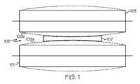
図1は、分かり易くするために必ずしも精確な縮尺ではない、従来の2つの成形ロール101、103の概略図である。図示のように、成形ロールが互いに離隔配置され、溶融ガラス107のストリームを受け取るためのガラス成形ギャップ105を画成している。成形ロール101、103は、溶融ガラス107のストリームからの加熱(たとえば約1000℃以上)によって半径方向に不均一に膨張し得る。例えば、破線109a、109bで示すように、溶融ガラス107のストリームによる成形ロール101、103の加熱によって、各々の成形ロールの作業領域表面が、作業領域表面の長さにわたり、対応する回転軸から半径方向に不均一に膨張し得る。成形ロール101、103の中心部が対応する成形ロール101、103の端部より高い温度に上昇するため、この不均一な半径方向の膨張が生じる。この不均一な半径方向の膨張により、成形ロールによって成形されたガラスリボンが、結果としてガラスリボンの対向する端部と比較して相対的に薄い中心部を有することになる。 FIG. 1 is a schematic diagram of two conventional forming
成形ロールの加熱時の半径方向の膨張によって厚さプロファイルが実質的に変化しない、ガラスリボンの成形に使用できる成形ロールの提供が望まれている。 It would be desirable to provide a forming roll that can be used to form a glass ribbon that does not substantially change the thickness profile due to radial expansion upon heating of the forming roll.
以下は、詳細な説明に記載してある幾つかの例示的な態様の基本的な理解を提供するために、本開示の簡単な概要を述べるものである。 The following presents a simplified summary of the disclosure in order to provide a basic understanding of some example aspects described in the detailed description.
第1の態様において、ロール成形装置が、溶融ガラスのストリームを供給するガラス供給装置と、成形本体から離隔配置された少なくとも1つの成形ロールであって、成形本体と成形ロールとの間に溶融ガラスのストリームを受け取って成形厚を有するガラスリボンを成形する成形ギャップを画成する、少なくとも1つの成形ロールとを備えている。成形ロールは、溶融ガラスのストリームに係合する作業領域表面を有する、作業領域部を備えている。作業領域表面は成形ロールの回転軸に沿って延びる長さを有している。成形ロールは、成形ロールの回転軸に対し鋭角に延びる熱抵抗境界を更に有している。 1st aspect WHEREIN: A roll forming apparatus is the glass supply apparatus which supplies the stream of molten glass, and at least 1 forming roll spaced apart from the shaping | molding main body, Comprising: Molten glass between a shaping | molding main body and a shaping | molding roll And at least one forming roll defining a forming gap for forming a glass ribbon having a forming thickness. The forming roll includes a work area portion having a work area surface that engages a stream of molten glass. The work area surface has a length extending along the axis of rotation of the forming roll. The forming roll further has a thermal resistance boundary extending at an acute angle with respect to the rotation axis of the forming roll.
第1の態様の1つの実施例において、熱抵抗境界は、作業領域部の温度が第1の温度から第2の温度に上昇したとき、作業領域表面が、作業領域表面の長さにわたり、回転軸から半径方向に実質的に均一に膨張するように構成されている。 In one embodiment of the first aspect, the thermal resistance boundary is such that when the temperature of the work area portion increases from the first temperature to the second temperature, the work area surface rotates over the length of the work area surface. It is configured to expand substantially uniformly in the radial direction from the shaft.
第1の態様の別の実施例において、熱抵抗境界は、作業領域部の円錐台形端面を含んでいる。 In another embodiment of the first aspect, the thermal resistance boundary includes a frustoconical end face of the working area portion.
第1の態様の更に別の実施例において、熱抵抗境界は、成形ロールの回転軸を中心に放射状に離隔配置された複数のボア穴を含んでいる。 In yet another embodiment of the first aspect, the thermal resistance boundary includes a plurality of bore holes spaced radially about the axis of rotation of the forming roll.
第1の態様の更に別の実施例において、熱抵抗境界は、成形ロール内に画成された円錐台形溝を含んでいる。例えば、円錐台形溝は、溝内に配置された1つ又は複数の強度要素を備えることができる。 In yet another embodiment of the first aspect, the thermal resistance boundary includes a frustoconical groove defined in the forming roll. For example, the frustoconical groove can comprise one or more strength elements disposed within the groove.
第1の態様の更に別の実施例において、成形ロールは、成形ロールを流体冷却するように構成された冷却流路を有している。 In yet another embodiment of the first aspect, the forming roll has a cooling channel configured to fluidly cool the forming roll.
第1の態様の更に別の実施例において、ロール成形装置は、少なくとも1つのギャップリング対を更に備え、ギャップリング対によって成形ロールと成形本体とが離隔配置されて、ガラス成形ギャップが画成される。 In yet another embodiment of the first aspect, the roll forming apparatus further comprises at least one gap ring pair, wherein the forming roll and the forming body are spaced apart by the gap ring pair to define a glass forming gap. The
第1の態様の更に別の実施例において、ギャップリング対は、成形ロールの作業領域部に取り付けられている。 In yet another embodiment of the first aspect, the gap ring pair is attached to the working area of the forming roll.
第1の態様の更に別の実施例において、鋭角は約30°〜約60°である。 In yet another embodiment of the first aspect, the acute angle is between about 30 degrees and about 60 degrees.
第1の態様は、単独、又は、前述の第1の態様の実施例の1つ若しくは任意の組合せと一緒に実施することができる。 The first aspect can be performed alone or in combination with one or any combination of the embodiments of the first aspect described above.
第2の態様において、成形ロールが、溶融ガラスに係合する作業領域表面を有する、作業領域部を備えている。作業領域表面は、成形ロールの回転軸に沿って延びる長さを有している。成形ロールは、成形ロール内に画成され、成形ロールの回転軸に対し鋭角に延びる円錐台形溝を更に備えている。 In the second aspect, the forming roll includes a work area portion having a work area surface engaged with the molten glass. The work area surface has a length extending along the rotation axis of the forming roll. The forming roll further includes a frustoconical groove defined in the forming roll and extending at an acute angle with respect to the rotation axis of the forming roll.
第2の態様の1つの実施例において、円錐台形溝は、作業領域部の温度が第1の温度から第2の温度に上昇したとき、作業領域表面が、作業領域表面の長さにわたり、回転軸から半径方向に実質的に均一に膨張するように構成されている。 In one embodiment of the second aspect, the frustoconical groove rotates the work area surface over the length of the work area surface when the temperature of the work area portion increases from the first temperature to the second temperature. It is configured to expand substantially uniformly in the radial direction from the shaft.
第2の態様の別の実施例において、成形ロールは、成形ロールを流体冷却するように構成された冷却流路を更に備えている。 In another embodiment of the second aspect, the forming roll further comprises a cooling channel configured to fluidly cool the forming roll.
第2の態様の更に別の実施例において、成形ロールは、作業領域部に取り付けられた少なくとも1つのギャップリングを更に備えている。 In yet another embodiment of the second aspect, the forming roll further comprises at least one gap ring attached to the working area portion.
第2の態様の更に別の実施例において、鋭角は約30°〜約60°である。 In yet another embodiment of the second aspect, the acute angle is from about 30 ° to about 60 °.
第2の態様の別の実施例において、円錐台形溝は、成形ロールの半径の約50%〜約85%の範囲内の深さまで、作業領域表面内に延びている。 In another embodiment of the second aspect, the frustoconical groove extends into the work area surface to a depth in the range of about 50% to about 85% of the radius of the forming roll.
第2の態様は、単独、又は、前述の第2の態様の実施例の1つ若しくは任意の組合せと一緒に実施することができる。 The second aspect can be implemented alone or together with one or any combination of the embodiments of the second aspect described above.
第3の態様において、離隔配置され、間にガラス成形ギャップを画成する少なくとも1つの成形ロールと成形本体とを用いて、ガラスリボンを成形する方法が提供される。成形ロールは、成形ロールの回転軸に沿って延びる長さを有する作業領域表面を有する、作業領域部を備えている。成形ロールは、成形ロールの回転軸に対し鋭角に延びる熱抵抗境界を更に有している。本方法は、(I)溶融ガラスのストリームを供給するステップ、及び(II)溶融ガラスのストリームをギャップに送り込んで、成形厚を有するガラスリボンを成形するステップを有している。熱抵抗境界によって、溶融ガラスによる作業領域部の加熱に応じ、作業領域表面の長さにわたり、作業領域表面が回転軸に対し半径方向に実質的に均一に膨張するのが容易になる。 In a third aspect, a method is provided for forming a glass ribbon using at least one forming roll and a forming body spaced apart and defining a glass forming gap therebetween. The forming roll includes a work area portion having a work area surface having a length extending along the rotation axis of the forming roll. The forming roll further has a thermal resistance boundary extending at an acute angle with respect to the rotation axis of the forming roll. The method includes (I) supplying a stream of molten glass, and (II) feeding the stream of molten glass into the gap to form a glass ribbon having a forming thickness. The thermal resistance boundary facilitates substantially uniform expansion of the work area surface in the radial direction with respect to the rotation axis over the length of the work area surface in response to heating of the work area portion by the molten glass.
第3の態様の1つの実施例において、ステップ(II)の熱抵抗境界は、作業領域部の円錐台形端面として提供される。 In one embodiment of the third aspect, the thermal resistance boundary of step (II) is provided as a frustoconical end face of the working area portion.
第3の態様の別の実施例において、ステップ(II)の熱抵抗境界は、成形ロールの回転軸を中心に放射状に離隔配置された複数のボア穴として提供される。 In another embodiment of the third aspect, the thermal resistance boundary of step (II) is provided as a plurality of bore holes spaced radially about the axis of rotation of the forming roll.
第3の態様の更に別の実施例において、ステップ(II)の熱抵抗境界は、成形ロール内に画成された円錐台形溝として提供される。例えば、本方法は、円錐台形溝を、溝内に配置された複数の強度要素を用いて強化する、第1のステップを有することができる。 In yet another embodiment of the third aspect, the thermal resistance boundary of step (II) is provided as a frustoconical groove defined in the forming roll. For example, the method can include a first step of strengthening the frustoconical groove using a plurality of strength elements disposed within the groove.
第3の態様の別の実施例において、本方法は成形ロールを流体で冷却するステップを更に有している。例えば、冷却するステップは、成形ロールの回転軸に沿って延びる冷却流路を通して流体を流すことを含むことができる。別の実施例において、冷却するステップは、成形ロールの内側中心部に対し流体を流し、溶融ガラスによる作業領域部の加熱に応じ、作業領域表面の長さにわたり、作業領域表面が実質的に均一に膨張するのを容易にすることを含むことができる。 In another embodiment of the third aspect, the method further comprises cooling the forming roll with a fluid. For example, the cooling step can include flowing a fluid through a cooling channel that extends along the axis of rotation of the forming roll. In another embodiment, the cooling step comprises flowing a fluid to the inner center of the forming roll and substantially uniform the work area surface over the length of the work area surface in response to heating of the work area by molten glass. To facilitate expansion.
第3の態様の別の実施例において、本方法は、作業領域部の外周縁部に熱を誘導し、溶融ガラスによる作業領域部の加熱に応じ、作業領域表面の長さにわたり、作業領域表面が実質的に均一に膨張することを容易にするステップを更に有することができる。 In another embodiment of the third aspect, the method induces heat to the outer peripheral edge of the work area portion and over the length of the work area surface in response to heating of the work area portion by molten glass. The method may further comprise the step of facilitating a substantially uniform expansion.
第3の態様の更に別の実施例において、鋭角は、約30°〜約60°である。 In yet another embodiment of the third aspect, the acute angle is from about 30 ° to about 60 °.
第3の態様は、単独、又は、前述の第3の態様の実施例の1つ若しくは任意の組合せと一緒に実施することができる。 The third aspect can be implemented alone or in combination with one or any combination of the embodiments of the third aspect described above.
添付図面を参照しながら以下の詳細な説明を読むことによって、これ等及び他の態様をより良く理解できる。 These and other aspects can be better understood by reading the following detailed description with reference to the accompanying drawings.
以下、例示的な実施の形態を示す添付図面を参照して、実施例について更に詳細に説明する。図面全体を通し、可能な限り、同一又は同様の部品には同じ参照番号を用いている。しかし、態様は多くの異なる形態で具体化することができ、本明細書に記載の実施の形態に限定されると解釈されるべきではない。 Hereinafter, examples will be described in more detail with reference to the accompanying drawings showing exemplary embodiments. Wherever possible, the same reference numbers will be used throughout the drawings to refer to the same or like parts. However, aspects may be embodied in many different forms and should not be construed as limited to the embodiments set forth herein.
本開示のロール成形装置は、その後ガラスシートに分離して様々な用途に使用できるガラスリボンの製造に有用であり得る。例えば、ガラスシートは液晶ディスプレイ(LCDs)、電気泳動ディスプレイ(EPD)、有機発光ダイオードディスプレイ(OLEDs)、プラズマディスプレイパネル(PDPs)等の製造に用いることができる。 The roll forming apparatus of the present disclosure can be useful for producing a glass ribbon that can then be separated into glass sheets and used in various applications. For example, glass sheets can be used in the manufacture of liquid crystal displays (LCDs), electrophoretic displays (EPD), organic light emitting diode displays (OLEDs), plasma display panels (PDPs), and the like.
図2〜4において、1つの例示的なロール成形装置201は、溶融ガラス205のストリームを供給するガラス供給装置203を備えることができる。図2に示すように、ガラス供給装置203はフィッシュテール型スロット供給部を含むことができるが、別の実施例では別のガラス供給装置を備えることができる。例えば、ガラス供給装置は、フュージョンダウンドロー装置、フュージョンアップドロー装置、リドロー装置、又は溶融ガラス205のストリームを供給することができる他のガラス供給装置を含むことができる。 2-4, one exemplary
図示のように、ロール成形装置201は、成形本体209から離隔配置された少なくとも1つの成形ロール207を備えている。成形ロール及び成形本体は様々な選択肢の耐火材料(例えば、セラミック、白金等)を含むことができる。成形ロール及び成形本体の製造に使用される材料は、成形ロール及び成形本体の構造的完全性を維持しながら、溶融ガラスをガラスリボンに成形することができる。更に、成形ロール及び成形本体は成形されたガラスリボンの主表面に接触するため、成形ロール及び成形本体は成形されたガラスリボンの主表面を損傷あるいは汚染しない材料から成る必要がある。例えば、成形本体は様々な金属合金(例えば、ステンレス鋼、ニッケル合金)から成ることができる。 As shown in the figure, the
成形ロール207と成形本体209とによって、溶融ガラス205のストリームを受け取るガラス成形ギャップ211を成形ロール207と成形本体209との間に画成することができる。図2〜4に示すように、成形本体209は成形ロール207と同じでも異なっていてもよい成形ロールを含むことができる。図示していないが、別の実施例において、成形本体209を成形ロール207と同一又は同様ではない別の部材として提供することもできる。例えば、成形本体209は、成形ロール207と連携してガラス成形ギャップ211を画成することができる(回転可能又は回転不能な)部材を含むことができる。ガラスリボン213は、成形ロール207と成形本体209との間のガラス成形ギャップ211を溶融ガラス205のストリームが通過することにより、成形することができる。ガラスリボン213は、ガラス成形ギャップ211の幅W(図4参照)に対応する厚さT(図3参照)で成形することができる。 By the forming
図2及び4に示すように、成形ロール207は、溶融ガラス205のストリームに係合する作業領域表面217を有する作業領域部215を備えている。作業領域表面217は円筒形状であってよいが、別の実施例において、作業領域表面は多角筒形状又は他の形状表面を含むことができる。更に、図示のように、作業領域表面217は成形ロール207の回転軸219に沿って延びる長さLを有している。本開示の成形ロールは、成形ロールの回転軸に対し鋭角に延びる少なくとも1つの熱抵抗境界を更に有している。例えば、図示のように、少なくとも1つの熱抵抗境界は、成形ロールの回転軸に対し鋭角αに延びる第1の熱抵抗境界、及び成形ロールの回転軸に対し別の鋭角βに延びる第2の熱抵抗境界を含むことができる。図示のように、一部の実施の形態において、鋭角α、βは互いに同一かつ反対方向に向いていてよいが、別の実施例ではこれ等の鋭角は異なっていてよい。鋭角α、βは約30°〜約60°の範囲内の絶対値を有することができるが、別の実施例では別の鋭角を設けることができる。互いに反対の鋭角α、βを設定することによって、図4に示す台形の断面部分401を有する鳩尾形の外周部の生成に役立つ。 As shown in FIGS. 2 and 4, the forming
図4に示すように、第1及び第2の熱抵抗境界を成形ロールのそれぞれの端部403、405に設け、熱をより効果的に作業領域部215内に保持できるようにすることができる。事実、熱抵抗境界によって、作業領域部からの熱伝達に対し熱抵抗が相対的に高い場所が提供され、それによって作業領域部215から出て成形ロール207の端部403、405に至る熱伝達の抑制に役立つ。一方、熱抵抗境界の角度α、βによって、作業領域部215の望ましい熱分布特性を得ることができる。事実、熱抵抗境界を成形ロール207の回転軸に対して反対の鋭角α、βに設けることによって、溶融ガラス205のストリームからの熱が保持され、作業領域部215全体に適切に分布させられるように、図示の台形の断面部分401を有する鳩尾形の外周部を設けることができる。その結果得られた作業領域部215の熱分布によって、溶融ガラス205による作業領域部215に対する第1の温度から第2の温度への加熱に応じ、作業領域表面217の長さLにわたり、作業領域表面217が回転軸219に対し半径方向に実質的に均一に膨張する、望ましい温度分布プロファイルが得られる。加熱中における作業領域表面217の実質的に均一な半径方向の膨張によって、成形ロール207の加熱及び冷却サイクルを通し、作業領域表面217が、作業領域表面217の長さLにわたり、実質的に均一な半径を維持することができる。 As shown in FIG. 4, first and second thermal resistance boundaries can be provided at the respective ends 403 and 405 of the forming roll so that heat can be held more effectively in the
熱抵抗境界は幅広い様々な代替構成が可能である。例えば、図4は第1の円錐台形溝407を含む第1の熱抵抗境界、及び第2の円錐台形溝409を含む第2の熱抵抗境界を示している。各々の円錐台形溝407、409は、成形ロール207の回転軸219に対しそれぞれ鋭角α、βに延びるように、成形ロール207内に画成することができる。円錐台形溝407、409は成形ロール207の周囲を完全に、部分的に、又は間欠的に延びることができる。例えば、図示のように、円錐台形溝407、409は、それぞれ成形ロール207の周囲を連続的かつ完全に延びている。一方又は両方の円錐台形溝を成形ロールの周囲を完全に延びる連続円錐台形溝として設けることにより、作業領域部の外部への熱伝導に対し、より有効な境界を設定することができる。別の方法として、一方又は両方の円錐台形溝を、成形ロール207の周囲に離隔配置された整列溝部分のように、不連続性を有するものとすることができる。不連続によって熱抵抗が低い点が生じ得るが、不連続によって、連続円錐台形溝では達成し得ない成形ロールの構造的完全性が得られる。 A wide variety of alternative configurations for the thermal resistance boundary are possible. For example, FIG. 4 shows a first thermal resistance boundary that includes a first
図4に更に示すように、円錐台形溝407、409は、作業領域表面217から深さ“d”まで延びることができる。成形ロール207の構造的完全性を維持しながら、様々な深さの範囲を設定して十分な熱抵抗境界を提供することができる。例えば、図示のように、成形ロールは、成形ロール207の半径“R”の2倍の直径“D”を有することができる。円錐台形溝407、409の深さ“d”は成形ロール207の半径“R”の約50%〜約85%の範囲とすることができるが、別の実施例では別の深さを提供することができる。 As further shown in FIG. 4, the
図2〜4に更に示すように、ロール成形装置201はギャップリング対221、223も備えることができ、このギャップリング対221、223によって成形ロール207と成形本体209とが互いに離隔配置され、ガラス成形ギャップ211が画成される。成形ロール207及び成形本体209の熱抵抗境界は、成形ロール及び成形本体の半径方向の膨張時に長さLに沿って実質的に均一な幅Wを維持するように構成されるが、この半径方向の膨張時に、実質的に一定の幅Wが維持されるようにギャップリング221、223を構成することができる。図2〜4に示す実施例において、ギャップリング221、223が成形ロール207の作業領域部215に取り付けられ、作業領域表面217から距離Xだけ突出している。別の実施例において、ギャップリング221、223の一方又は両方を成形本体209の作業領域部225に取り付けることができ、作業領域部225の作業領域表面227から距離Xだけ突出させることができる。更に別の実施例において、図2において隠線でギャップリング222、224を更に示すように、成形ロール207及び成形本体209の両方が、それぞれ対応する作業領域表面217、227から距離X/2だけ突出したギャップリング対をそれぞれ有することができる。動作時、ギャップリングによって与えられる作業領域表面217、227間の合計間隔がXになるように、それぞれのギャップリング221と222及び223と224とが互いに係合することができる。 As further shown in FIGS. 2 to 4, the
従って、膨張時、ギャップリング対221、223によって、成形ロール207及び成形本体209の作業領域表面217、227が、距離Xに対応する一定の幅Wで確実に分離されたままの状態にすることができる。従って、作業領域表面217から所定の距離Xだけ突出するギャップリング対221、223を選択して、所定の距離Xに対応する実質的に均一な厚さTを有するガラスリボン213を成形することができる。従って、ギャップリングを使用しなければ必要である、幅Wが成形ロールの膨張時にどのように変化し得るかの予測を行う必要なく、1mm以下の均一な厚さの薄いガラスリボンを容易に成形することができる。更に、ロール成形工程において、ギャップリング221、223の温度が上昇すると、ギャップリング221、223そのものが膨張し得るが、(1mm以下の薄いガラスシートを成形する場合のように)距離Xが小さい場合、距離Xの膨張はごく僅かである。その上、ギャップリング221、223を熱伝導率の低いセラミックコーティングで被覆したもの、又は熱膨張率の低い材料を含むものとすることにより、距離Xの膨張に与える熱の影響を抑制することができる。 Therefore, during expansion, the working area surfaces 217 and 227 of the forming
ギャップリング対221、223は成形ロール207及び/又は成形本体209と一体とすることも、成形ロール207及び/又は成形本体209に別に取り付けることもできる。加えて、前述のように、成形本体209に取り付けられ、成形ロール207の第1のギャップリング対221、223に接触する第2のギャップリング対(図示せず)が存在し得る。更に、ここに示した実施例は、成形ロール207の作業領域部215に取り付けられたギャップリング対221、223を示しているが、別の方法として、これ等を成形ロール207の端部403、405に取り付けることができる。しかし、作業領域部215は溶融ガラス205からの熱を保持し、従って端部403、405とは異なる(かつより速い)速度で膨張するため、ギャップリング221、223を作業領域部215、225に取り付けることによって長さLに沿った幅Wのより良い制御が可能になる。換言すれば、ギャップリング221、223を端部403、405に取り付けることによって、端部403、405が一定の距離で離隔された状態になることが保証されるが、作業領域表面217、227が端部403、405とは異なる速度で膨張し得るため、作業領域表面217、227が一定の距離で離隔された状態になることを保証することはできない可能性がある。 The gap ring pairs 221 and 223 can be integrated with the forming
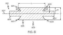
図4に示すように、成形ロール207及び成形本体209の各々は同様(たとえば図示のような同一)の熱抵抗境界の構成を有することができる。事実、前述のように成形本体209は、成形ロール207と成形本体209とによって、図示のように実質的に同一の成形ロール対が形成されるように、成形ロール207と同一であってよい。成形ロール及び成形本体の一方又は両方が熱抵抗境界の別の構造を有することができる。例えば、成形ロール207及び/又は成形本体209の一方又は両方が、図5及び6に示す成形ロール501を含むことができる。成形ロール501は、溶融ガラス205のストリームに係合する作業領域表面505を有する作業領域部503を備えている。作業領域表面505は、成形ロール501の回転軸507に沿って延びる長さLを有している。図6に示すように、成形ロール501は、第1の円錐台形端面601を含む第1の熱抵抗境界、及び第2の円錐台形端面603を含む第2の熱抵抗境界を有している。円錐台形端面601、603の各々は、成形ロール501の回転軸507に対してそれぞれ鋭角α、βに延びることができる。 As shown in FIG. 4, each of the forming
図6に更に示すように、円錐台形端面601、603は作業領域表面505内に深さ“d”まで延びることができる。成形ロール501の構造的完全性を維持しながら、様々な深さの範囲を設定して十分な熱抵抗境界を提供することができる。例えば、図示のように、成形ロールは、成形ロール501の半径“R”の2倍の直径“D”を有することができる。円錐台形端面601、603の深さ“d”は成形ロール501の半径“R”の約50%〜約85%の範囲とすることができるが、別の実施例では別の深さが提供されてもよい。 As further shown in FIG. 6, the frustoconical end surfaces 601, 603 can extend into the working
図6に示すように、端面601、603は成形ロール501の端部605、607の対応する面に対向していない。従って、図5及び6の熱抵抗境界は、熱伝達に対し図2〜4の熱抵抗境界より高い熱抵抗を有することができる。図示してないが、成形ロール501は、成形ロール501の構造強度を強化するために、必要に応じ、回転軸507を中心に放射状に延び、端面601、603とそれぞれの端部605、607との間にまたがる複数の強化リブを含むことができる。 As shown in FIG. 6, the end surfaces 601 and 603 do not face the corresponding surfaces of the
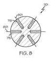
更に別の実施例において、成形ロール及び成形本体の一方又は両方が、図7及び8に示す成形ロール701を含むことができる。成形ロール701は、溶融ガラス205のストリームに係合する作業領域表面705を有する作業領域部703を備えている。作業領域表面705は、成形ロール701の回転軸707に沿って延びる長さLを有している。成形ロール701は、第1の複数のボア穴709を含む第1の熱抵抗境界、及び第2の複数のボア穴711を含む第2の熱抵抗境界を備えている。各々のボア穴715の陰線713で示すように、ボア穴はボア穴軸801(図8参照)に沿って、円錐台形の断面8−8で示すように、成形ロール701の回転軸707に対しそれぞれ鋭角α、βに延びることができる。図8は、図7の対応する円錐台形の面8−8に沿った、成形ロール701の回転軸707を中心に放射状に離隔配置されたボア穴715の配列を示している。ボア穴715は互いに等間隔であってもそうでなくてもよい。更に、ボア穴715の数、深さ、及び寸法は図示の実施例と異なっていてもよい。これらの代替的な実施の形態において、各々のボア穴軸801がそれぞれ鋭角α、βに延びているため、熱抵抗境界も同様に成形ロール701の回転軸に対し鋭角に延びている。熱抵抗境界をそれぞれ複数のボア穴として設けることにより、成形ロールのかなりの部分を除去して熱抵抗境界を作製する他の設計と比較した場合、強化された構造的完全性が得られる。 In yet another embodiment, one or both of the forming roll and the forming body can include the forming
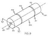
更に別の実施例において、成形ロール及び成形本体の一方又は両方が、図9及び10に示す成形ロール901を含んでいてもよい。成形ロール901は溶融ガラス205のストリームに係合する作業領域表面905を有する作業領域部903を備えている。作業領域表面905は、成形ロール901の回転軸907に沿って延びる長さLを有している。成形ロール901は、第1の円錐台形溝909を含む第1の熱抵抗境界、及び第2の円錐台形溝911を含む第2の熱抵抗境界を備えている。各々の円錐台形溝909、911は、成形ロール901の回転軸907に対しそれぞれ前述の鋭角α、βに延びるように、成形ロール901内に画成することができる。図4に示す円錐台形溝407、409と同様に、円錐台形溝909、911は、成形ロール901の周囲を完全に、部分的に、又は間欠的に延びることができる。例えば、図示のように、円錐台形溝909、911は、それぞれ成形ロール901の周囲を完全に延びている。一方又は両方の円錐台形溝を、成形ロール901の周囲を完全に延びる円錐台形溝として設けることにより、作業領域部の外部への熱伝導に対し、より有効な境界を設定することができる。 In yet another embodiment, one or both of the forming roll and the forming body may include a forming
別の方法として、必要に応じ、一方又は両方の円錐台形溝を不連続とし、連続円錐台形溝では達成し得ない成形ロールの構造的完全性を達成することができる。例えば、図10に示すように、円錐台形溝909、911の各々は、成形ロール901を強化するために溝内に配置された、図示の溶接ポイント1001、1003等の複数の強度要素を有することができる。溶接ポイント1001、1003は作業領域部903を成形ロール901の端部913、915に取り付けることによって、成形ロール901に強度と剛性を付加する。溶接ポイント1001、1003は、成形ロール901の周囲を完全又は部分的に延びることができる。また、各溝内に複数の溶接点が存在することができる。更に、溶接ポイント1001、1003は、成形ロール901の表面により近くなるように半径方向に配置することも、成形ロール901の回転軸に近くなるように溝内により深く配置することもできる。 Alternatively, if desired, one or both frustoconical grooves can be made discontinuous to achieve structural integrity of the forming roll that cannot be achieved with a continuous frustoconical groove. For example, as shown in FIG. 10, each of the
本開示の成形ロールは、任意の冷却流路も備えることができる。例えば、図10に示すように、成形ロール901は、成形ロール901を流体冷却するように構成された任意の冷却流路1007を備えている。一部の実施例において、冷却流路1007は成形ロール901と同軸であってよく、作業領域部903にわたって延びている。図10に更に示すように、円錐台形溝909、911は作業領域表面905内に深さ“d”まで延びることができる。成形ロール903の構造的完全性を維持しながら、様々な深さの範囲を設定して十分な熱抵抗境界を提供することができる。例えば、図示のように、成形ロールは、成形ロール903の半径“R1”の2倍の直径“D”を有することができる。更に、冷却流路1007は半径“R2”を有することができ、壁厚“WT”が作業領域表面905と冷却流路1007の内壁面との間に形成される。円錐台形溝909、911の深さ“d”は成形ロール903の壁厚“WT”の約50%〜約85%の範囲とすることができるが、別の実施例では別の深さが提供されてもよい。 The forming roll of the present disclosure can also include an optional cooling channel. For example, as shown in FIG. 10, the forming
この冷却流路1007に冷却流体を供給し、冷却流体ストリーム1009として分散して、ロール成形処理の間、成形ロール901を冷却し成形ロールの膨張を抑制することができる。冷却流体は水、圧縮空気、又は別の特定の冷却流体であってよい。図10に示すように、導管1005を冷却流路1007の内部に設けて冷却流体を供給し、冷却流体ストリーム1009を成形ロール901の内側中心部に誘導することができる。 A cooling fluid can be supplied to the
ロール成形処理の間、成形ロール901の中心部が成形ロール901の外周部よりも多くの熱を受ける。従って、冷却流体を成形ロール901の中心部に誘導することによって、中心部が作業領域部903の外周部と実質的に同じ速度で膨張するように中心部の温度を制御することができる。従って、成形ロール901の内側中心部に対して流体ストリーム1009を誘導することによって、作業領域表面905が、溶融ガラス205のストリームによる作業領域部903の加熱に応じ、作業領域表面905の長さLにわたり、実質的に均一に膨張するのを容易にすることができる。 During the roll forming process, the center portion of the forming
図10に示すように、冷却流路を通して冷却流体を流すことに加え、又は流すことに代え、熱Hを作業領域部903の外周縁部に誘導して、作業領域表面905が、溶融ガラスによる作業領域部903の加熱に応じ、作業領域表面905の長さLにわたり、実質的に均一に膨張するのを容易にすることができる。熱を作業領域部903の外周縁部に誘導することによって、外周部が作業領域部903の中心部と実質的に同じ速度で膨張するように、外周部の温度を制御することができる。 As shown in FIG. 10, in addition to or instead of flowing the cooling fluid through the cooling flow path, heat H is guided to the outer peripheral edge of the
ガラスリボン213を成形する方法について説明するが、本開示の例示的な成形ロール/成形本体の構成の何れにも適用することができる。本方法は、離隔配置され、間にガラス成形ギャップを画成する少なくとも1つの成形ロール及び成形本体を用いて実施することができる。前述のように、成形本体は様々な構成を採ることができ、成形ロールと同様又は同じであってもよい。例えば、図2及び4に示すように、成形ロール207及び成形本体209は、それぞれ対応する成形ロール207及び成形本体209の回転軸219に沿って延びる長さLを有する作業領域表面217、227を有する、作業領域部215、225を備えたものとされる。前述のように、成形ロール及び成形本体は、それぞれの回転軸(例えば、回転軸219)対してそれぞれ鋭角α、βに延びる、成形ロール207内に画成された円錐台形溝407、409を含む熱抵抗境界を各々備えていてもよい。本方法は鋭角α、βを約30°〜約60°の範囲内とすることができるが、別の実施例では別の鋭角が用いられてもよい。 A method of forming the
前述のように、別の実施例において、熱抵抗境界の別の構成を用いることができる。例えば、図5及び6は、作業領域部503の円錐台形端面601、603を含む熱抵抗境界を示している。図7及び8は、熱抵抗境界が成形ロールの回転軸707を中心に放射状に離隔配置された複数のボア穴709、711を含む、別の実施例を示している。図9及び10に示すように、別の実施例では、溝内に配置された複数の強度要素(例えば、溶接ポイント1001、1003)を有する円錐台形溝909、911として、熱抵抗境界が提供される。 As described above, in other embodiments, other configurations of thermal resistance boundaries can be used. For example, FIGS. 5 and 6 show a thermal resistance boundary including the frustoconical end faces 601 and 603 of the
図2及び3において、本方法は、溶融ガラス205のストリームを供給するステップ、及び溶融ガラスのストリームをギャップ211に送り込んで成形厚Tを有するガラスリボン213を成形するステップを更に有することができる。本開示の各々の実施例の熱抵抗境界によって、溶融ガラスによる作業領域部の加熱に応じ、作業領域表面の長さにわたり、回転軸に対し作業領域表面が半径方向に実質的に均一に膨張するのが容易になる。1つの実施例において、本方法は成形ロールを流体で冷却するステップを更に有することができる。例えば、図10に示すように、本方法は成形ロール901の回転軸907に沿って延びる冷却流路1007を通して流体を流すことを含むことができる。更に図示するように、本方法は、例えば冷却流体ストリーム1009によるなどして、成形ロールの内側中心部に流体を流すことによって冷却するステップを有することができる。成形ロールの内側中心部に対して流体を流すことによって、溶融ガラス205による作業領域部903の加熱に応じ、作業領域表面905の長さLにわたり、作業域面905が実質的に均一に膨張するのが容易になる。 2 and 3, the method may further comprise the steps of providing a stream of
更に、図10において“H”で模式的に示すように、本方法は作業領域部903の外周縁部を加熱して、溶融ガラス205による作業領域部903の加熱に応じ、作業領域表面905の長さLにわたり、作業領域表面905が実質的に均一に膨張するのを容易にするステップを有することもできる。 Further, as schematically shown by “H” in FIG. 10, the present method heats the outer peripheral edge of the
特許請求した本発明の精神及び範囲を逸脱せずに、様々な改良及び変形が可能であることは当業者にとって明白であろう。 It will be apparent to those skilled in the art that various modifications and variations can be made without departing from the spirit and scope of the claimed invention.
201 ロール成形装置
203 ガラス供給装置
205 溶融ガラス
207、501、701、901 成形ロール
209 成形本体
211 ガラス成形ギャップ
213 ガラスリボン
215、503、703、903 作業領域部
217、505、705、905 作業領域表面
219、507、707、907 回転軸
221、222、223、224 ギャップリング
407、409、909、911 円錐台形溝
601、603 円錐台形端面
709、711 複数のボア穴
715 各ボア穴
1001、1003 溶接ポイント
1007 冷却流路DESCRIPTION OF
Claims (11)
Translated fromJapanese溶融ガラスのストリームを供給するガラス供給装置と、
成形本体から離隔配置された少なくとも1つの成形ロールであって、前記成形本体と該成形ロールとの間に前記溶融ガラスのストリームを受け取って成形厚を有するガラスリボンを成形する成形ギャップを画成する、少なくとも1つの成形ロールと、
を備え、
前記成形ロールが、該成形ロールの回転軸に沿って延びる長さを有する作業領域表面であって、前記溶融ガラスのストリームに係合する作業領域表面を有する、作業領域部を備え、
前記成形ロールが、該成形ロールの両端部の外周面から該成形ロールの前記回転軸に向かって且つ長さ方向内方に向かって前記作業領域部内に前記回転軸に対して斜めに延びて、前記作業領域部の温度が第1の温度から第2の温度に上昇したとき、前記作業領域表面が、該作業領域表面の前記長さに亘り、前記回転軸から半径方向に実質的に均一に膨張するように構成されてなる熱抵抗境界を有していることを特徴とする装置。A roll forming device,
A glass supply device for supplying a stream of molten glass;
At least one forming roll spaced apart from the forming body, defining a forming gap between the forming body and the forming roll for receiving the stream of molten glass and forming a glass ribbon having a forming thickness; At least one forming roll;
With
The forming roll has a working area surface having a working area surface having a length extending along a rotation axis of the forming roll, the working area surface engaging with the molten glass stream;
The molding roll extendsobliquely withrespect to the rotation axis in the work area partfrom the outer peripheral surface of both ends of the molding rolltoward the rotation axis of the molding roll andinward in the longitudinal direction, When the temperature of the work area rises from the first temperature to the second temperature, the work area surface is substantially uniform in the radial direction from the rotation axis over the length of the work area surface. apparatus characterized in that it has a thermal resistance boundarying configured to expand.
b.前記熱抵抗境界が、前記成形ロール内に画成された円錐台形溝を含んでいることを特徴とする請求項1記載の装置。a . The thermal resistance boundary includes a frustoconical end surface of the working area portion, and / or
b . The apparatus of claim 1, wherein the thermal resistance boundaryincludes a frustoconical groove defined in the forming roll.
前記斜めが約30°〜約60°であることを特徴とする請求項1から3いずれか1項記載の装置。Further comprising at least one gap ring pair, by the gap ring pairs, the forming roll and said molding body the glass shaped gap is spaced are defined,及Beauty <br/> theoblique about 4. A device accordingto any one of claims 1to 3 , characterized in that it is between 30 [deg.] And about 60 [deg.].
前記成形ロールの回転軸に沿って延びる長さを有する作業領域表面であって、溶融ガラスのストリームに係合する作業領域表面を有する、作業領域部と、
前記成形ロール内に画成され、該成形ロールの両端部の外周面から該成形ロールの前記回転軸に向かって且つ長さ方向内方に向かって前記作業領域部内に前記回転軸に対して斜めに延びて、前記作業領域部の温度が第1の温度から第2の温度に上昇したとき、前記作業領域表面が、該作業領域表面の長さに亘り、前記回転軸から半径方向に実質的に均一に膨張するように構成されてなる円錐台形溝と、
を備えたことを特徴とする成形ロール。A forming roll,
A work area surface having a length extending along the axis of rotation of the forming roll and having a work area surface that engages a stream of molten glass; and
It is defined in the forming roll, and isinclined with respect to the rotation axis in the work area partfrom the outer peripheral surface of both ends of the forming rolltoward the rotation axis of the forming roll and inwardin the longitudinal direction. And whenthe temperature of the working area rises from the first temperature to the second temperature, the working area surface substantially extends radially from the rotational axis over the length of the working area surface. a frustoconical grooveing configured to uniformly expands,
A forming roll characterized by comprising:
b.前記作業領域部に取り付けられた少なくとも1つのギャップリングを更に備える、
ことを特徴とする請求項5記載の成形ロール。a. Further comprising a cooling channel of the forming roll is configured to be in fluid cooling,及beauty <br/> b. And further comprising at least one gap ring attached to the working area portion.
The forming roll according to claim5 .
(I)溶融ガラスのストリームを供給するステップ、及び
(II)前記溶融ガラスのストリームを前記ギャップに送り込んで成形厚を有するガラスリボンを成形するステップを有し、前記成形ロールが、該成形ロールの両端部の外周面から該成形ロールの前記回転軸に向かって且つ長さ方向内方に向かって前記作業領域部内に前記回転軸に対して斜めに延びる熱抵抗境界を有し、該熱抵抗境界によって、前記溶融ガラスによる前記作業領域部の加熱に応じ、該作業領域表面の前記長さに亘り、前記作業領域表面が前記回転軸に対し半径方向に実質的に均一に膨張するのが容易になることを特徴とする方法。A method of forming a glass ribbon using at least one forming roll and a forming body that are spaced apart and define a glass forming gap therebetween, wherein the forming roll extends along a rotation axis of the forming roll. in a working area surface having a length,obtain Preparations work area part way extending,
(I) supplying a stream of molten glass; and (II) feeding the stream of molten glass into the gap to form a glass ribbon having a molding thickness, themolding roll comprising: has a thermal resistance boundaries extending obliquely relative to the rotation axis in the working area portion toward the toward the rotation axis and a length inwards of the shaped roll from the outer peripheral surface of both end portions, the thermal resistance boundary the response to heating of the working area portion by the molten glass, RiWataru the length of the working area surface, easier the working area surface substantially uniformly expand radially relative to the rotational axis A method characterized by becoming.
a.前記作業領域部の円錐台形端面、及び/又は前記成形ロール内に画成された円錐台形溝として、又は
b.前記成形ロールの前記回転軸を中心に放射状に離隔配置された複数のボア穴として、
提供されることを特徴とする請求項8記載の方法。The thermal resistance boundary of the step (II) is
a. As a frustoconical end face of the working areaand / ora frustoconical groove defined in the forming roll, or b. Asa plurality of bore holes radially spaced around the rotation axis of the forming roll,
9. The method of claim 8, wherein the method is provided.
当該方法が、前記円錐台形溝を、該溝内に配置された複数の強度要素によって強化するステップを更に有することを特徴とする請求項9記載の方法。The thermal resistance boundary of step (II) is provided as a frustoconical groove defined in the forming roll; and
10. The method of claim 9, further comprising the step of strengthening the frustoconical groove with a plurality of strength elements disposed within the groove.
b.前記成形ロールの前記回転軸に沿って延びる冷却流路を通して流体を流すことを含む、冷却するステップ、及び
c.前記作業領域部の外周縁部に熱を誘導し、前記溶融ガラスによる前記作業領域部の加熱に応じ、該作業領域表面の前記長さに亘り、前記作業領域表面が実質的に均一に膨張するのを容易にするステップ、
を更に有することを特徴とする請求項8又は9記載の方法。a. Cooling the forming roll with a fluid; and / or b. It includes flowing fluid through the cooling channel extending along the rotation axis of the forming roll, cooling step,及Beauty
c. Inducing heat to the outer periphery of the working area portion, depending on the heating of the working area portion by the molten glass, RiWataru the length of the working region surface, the work area surface substantially uniformly inflated Steps, which make it easy to
10. The method according to claim 8 or 9, further comprising:
Applications Claiming Priority (3)
| Application Number | Priority Date | Filing Date | Title |
|---|---|---|---|
| US201361858295P | 2013-07-25 | 2013-07-25 | |
| US61/858,295 | 2013-07-25 | ||
| PCT/US2014/046976WO2015013092A1 (en) | 2013-07-25 | 2014-07-17 | Methods and apparatus for forming a glass ribbon |
Publications (3)
| Publication Number | Publication Date |
|---|---|
| JP2016528145A JP2016528145A (en) | 2016-09-15 |
| JP2016528145A5 JP2016528145A5 (en) | 2017-09-07 |
| JP6490684B2true JP6490684B2 (en) | 2019-03-27 |
Family
ID=51298990
Family Applications (1)
| Application Number | Title | Priority Date | Filing Date |
|---|---|---|---|
| JP2016529788AExpired - Fee RelatedJP6490684B2 (en) | 2013-07-25 | 2014-07-17 | Method and apparatus for forming glass ribbon |
Country Status (7)
| Country | Link |
|---|---|
| US (2) | US9643872B2 (en) |
| EP (1) | EP3024785B1 (en) |
| JP (1) | JP6490684B2 (en) |
| KR (1) | KR102274255B1 (en) |
| CN (1) | CN105531236B (en) |
| TW (2) | TWI638786B (en) |
| WO (1) | WO2015013092A1 (en) |
Families Citing this family (39)
| Publication number | Priority date | Publication date | Assignee | Title |
|---|---|---|---|---|
| US9359251B2 (en) | 2012-02-29 | 2016-06-07 | Corning Incorporated | Ion exchanged glasses via non-error function compressive stress profiles |
| JP6490684B2 (en)* | 2013-07-25 | 2019-03-27 | コーニング インコーポレイテッド | Method and apparatus for forming glass ribbon |
| US11079309B2 (en) | 2013-07-26 | 2021-08-03 | Corning Incorporated | Strengthened glass articles having improved survivability |
| US10246365B2 (en) | 2013-10-09 | 2019-04-02 | Corning Incorporated | Apparatus and method for forming thin glass articles |
| US9701574B2 (en) | 2013-10-09 | 2017-07-11 | Corning Incorporated | Crack-resistant glass-ceramic articles and methods for making the same |
| US9517968B2 (en) | 2014-02-24 | 2016-12-13 | Corning Incorporated | Strengthened glass with deep depth of compression |
| TWI773291B (en) | 2014-06-19 | 2022-08-01 | 美商康寧公司 | Glasses having non-frangible stress profiles |
| MX2017001386A (en) | 2014-07-31 | 2017-08-21 | Corning Inc | Thermally tempered glass and methods and apparatuses for thermal tempering of glass. |
| US10611664B2 (en) | 2014-07-31 | 2020-04-07 | Corning Incorporated | Thermally strengthened architectural glass and related systems and methods |
| US11097974B2 (en) | 2014-07-31 | 2021-08-24 | Corning Incorporated | Thermally strengthened consumer electronic glass and related systems and methods |
| DE202015009904U1 (en) | 2014-10-08 | 2021-05-14 | Corning Incorporated | Glass-based item |
| US10150698B2 (en) | 2014-10-31 | 2018-12-11 | Corning Incorporated | Strengthened glass with ultra deep depth of compression |
| CN115536270A (en) | 2014-11-04 | 2022-12-30 | 康宁股份有限公司 | Deep non-fragile stress curve and method of making the same |
| US11613103B2 (en) | 2015-07-21 | 2023-03-28 | Corning Incorporated | Glass articles exhibiting improved fracture performance |
| US9701569B2 (en) | 2015-07-21 | 2017-07-11 | Corning Incorporated | Glass articles exhibiting improved fracture performance |
| CN108431726A (en) | 2015-07-30 | 2018-08-21 | 康宁公司 | Hot-reinforced glass and related system and method |
| US12338159B2 (en) | 2015-07-30 | 2025-06-24 | Corning Incorporated | Thermally strengthened consumer electronic glass and related systems and methods |
| WO2017020041A1 (en) | 2015-07-30 | 2017-02-02 | Corning Incorporated | Thermally strengthened glass and related systems and methods |
| KR102029948B1 (en) | 2015-12-11 | 2019-10-08 | 코닝 인코포레이티드 | Fusion-Formable Glass-Based Products Including Metal Oxide Concentration Gradients |
| KR101952085B1 (en) | 2016-01-12 | 2019-05-21 | 코닝 인코포레이티드 | Thin, thermally and chemically tempered glass-based products |
| US11795102B2 (en) | 2016-01-26 | 2023-10-24 | Corning Incorporated | Non-contact coated glass and related coating system and method |
| JP2019507090A (en) | 2016-01-29 | 2019-03-14 | コーニング インコーポレイテッド | Heat-enhanced photochromic glass and related systems and methods |
| US10017417B2 (en) | 2016-04-08 | 2018-07-10 | Corning Incorporated | Glass-based articles including a metal oxide concentration gradient |
| KR20210122313A (en) | 2016-04-08 | 2021-10-08 | 코닝 인코포레이티드 | Glass-based articles including a stress profile comprising two regions, and methods of making |
| US11453612B2 (en) | 2016-04-20 | 2022-09-27 | Corning Incorporated | Glass-based articles including a metal oxide concentration gradient |
| TWI729116B (en)* | 2016-04-21 | 2021-06-01 | 美商康寧公司 | Methods and apparatus for processing glass |
| CN105837007A (en)* | 2016-06-02 | 2016-08-10 | 平凉市老兵科技研发有限公司 | Device for manufacturing vacuum glass with protrusions |
| CN111065609A (en) | 2017-08-24 | 2020-04-24 | 康宁股份有限公司 | Glass with improved tempering capability |
| CN111491901B (en)* | 2017-10-31 | 2022-10-18 | 康宁公司 | Method of making a glass ribbon |
| TWI785156B (en) | 2017-11-30 | 2022-12-01 | 美商康寧公司 | Non-iox glasses with high coefficient of thermal expansion and preferential fracture behavior for thermal tempering |
| KR20210154825A (en) | 2019-04-23 | 2021-12-21 | 코닝 인코포레이티드 | Glass laminate with definite stress profile and method for manufacturing the same |
| KR102748256B1 (en) | 2019-06-26 | 2024-12-31 | 코닝 인코포레이티드 | Device for manufacturing ribbons |
| US11697617B2 (en) | 2019-08-06 | 2023-07-11 | Corning Incorporated | Glass laminate with buried stress spikes to arrest cracks and methods of making the same |
| US11414337B2 (en) | 2019-08-29 | 2022-08-16 | Owens-Brockway Glass Container Inc. | Forming glass containers from tubular parisons |
| EP4028367A4 (en) | 2019-09-12 | 2023-09-13 | Corning Incorporated | Methods and apparatus for manufacturing a glass ribbon |
| CN115734947A (en)* | 2020-06-19 | 2023-03-03 | 康宁公司 | Method of making a glass ribbon |
| WO2022072257A1 (en)* | 2020-10-02 | 2022-04-07 | Corning Incorporated | Methods and apparatus for manufacturing a glass ribbon |
| NL2027190B1 (en) | 2020-11-13 | 2022-06-30 | Corning Inc | Apparatus for, and method of, roll forming sheets of high refractive index glass |
| CN113429117B (en)* | 2021-08-11 | 2022-05-20 | 江西鼎盛新材料科技有限公司 | Forming device and forming method of microcrystalline glass |
Family Cites Families (31)
| Publication number | Priority date | Publication date | Assignee | Title |
|---|---|---|---|---|
| BE357209A (en)* | ||||
| US1816307A (en)* | 1926-11-06 | 1931-07-28 | American Bicheroux Company | Roll for rolling glass plates from molten glass |
| US1659053A (en)* | 1927-03-03 | 1928-02-14 | Edward Ford Plate Glass | Roll for rolling molten glass |
| US1772072A (en) | 1927-10-06 | 1930-08-05 | Libbey Owens Ford Glass Co | Process and apparatus for forming sheet glass |
| US1818152A (en)* | 1928-01-19 | 1931-08-11 | Libbey Owens Ford Glass Co | Process and apparatus for forming sheet glass |
| US1937382A (en)* | 1931-09-17 | 1933-11-28 | Libbey Owens Ford Glass Co | Fluid cooled roll |
| US2015747A (en)* | 1932-07-11 | 1935-10-01 | Libbey Owens Ford Glass Co | Roll construction |
| FR1582950A (en)* | 1968-08-27 | 1969-10-10 | ||
| US3653455A (en) | 1969-08-01 | 1972-04-04 | Allan E Hetteen | Off-road vehicle wheel suspension |
| JPS58137866A (en) | 1982-02-10 | 1983-08-16 | Canon Inc | Fixing device |
| JPS6045345U (en)* | 1983-09-07 | 1985-03-30 | セントラル硝子株式会社 | Roll for plate glass plate |
| JPS6389421A (en) | 1986-09-30 | 1988-04-20 | Nippon Electric Glass Co Ltd | Device for forming sheet glass |
| CN2088550U (en)* | 1991-03-26 | 1991-11-13 | 倪敏禄 | High-speed steel roller for glass making |
| FR2741335B1 (en) | 1995-11-22 | 1998-01-16 | Corning Inc | METHOD AND DEVICE FOR FORMING A SHEET IN A VITREOUS MATERIAL, BY PRESSING THE SHEET IN THE PASTY STATE BETWEEN CONTRAROTATIVE ROLLS |
| US5833455A (en)* | 1996-05-14 | 1998-11-10 | Bricmont, Inc. | Dry roll furnace arrangement |
| US5970747A (en) | 1996-11-07 | 1999-10-26 | Corning Incorporated | Apparatus for forming glass sheets with coaxial cavities |
| US5970474A (en) | 1997-04-24 | 1999-10-19 | Sears, Roebuck And Co. | Registry information system for shoppers |
| JPH11139837A (en)* | 1997-11-07 | 1999-05-25 | Ishizuka Glass Co Ltd | Sheet glass forming apparatus and forming method |
| US6250220B1 (en)* | 1999-08-10 | 2001-06-26 | Quad/Graphics, Inc. | Anti-wrinkle system for a web offset press |
| US20040093900A1 (en) | 2002-11-15 | 2004-05-20 | Fredholm Allan M. | Apparatus and method for producing sheets of glass presenting at least one face of very high surface quality |
| JP4291172B2 (en)* | 2004-02-05 | 2009-07-08 | 株式会社リコー | Conductive roller, process cartridge having the same, and image forming apparatus having the process cartridge |
| JP5016646B2 (en) | 2008-09-17 | 2012-09-05 | ニチアス株式会社 | Heat-resistant roll, manufacturing method thereof, and manufacturing method of plate glass using the same |
| EP2226299B1 (en) | 2009-02-23 | 2018-01-24 | Corning Incorporated | Glass manufacturing system and method for forming a high quality thin glass sheet |
| EP2258664A1 (en) | 2009-06-04 | 2010-12-08 | Corning Incorporated | Vertical rolling apparatus and method for producing a textured glass sheet |
| JP2012001762A (en) | 2010-06-16 | 2012-01-05 | Nippon Electric Glass Co Ltd | Vapor deposition method and vapor deposition device |
| US9003835B2 (en) | 2011-05-31 | 2015-04-14 | Corning Incorporated | Precision roll forming of textured sheet glass |
| WO2012166761A1 (en)* | 2011-05-31 | 2012-12-06 | Corning Incorporated | Precision glass roll forming process and apparatus |
| CN202465487U (en)* | 2012-03-23 | 2012-10-03 | 广东科迪微晶玻璃实业有限公司 | Calendaring and forming roller for glass ceramics |
| CN102603193B (en)* | 2012-03-28 | 2013-12-25 | 广东科迪微晶玻璃实业有限公司 | Production method for grinding-free and polishing-free black transparent microcrystalline glass plate |
| EP2738143B1 (en) | 2012-11-29 | 2015-07-08 | Corning Incorporated | Precision forming of sheet glass and sheet rolling apparatus |
| JP6490684B2 (en)* | 2013-07-25 | 2019-03-27 | コーニング インコーポレイテッド | Method and apparatus for forming glass ribbon |
- 2014
- 2014-07-17JPJP2016529788Apatent/JP6490684B2/ennot_activeExpired - Fee Related
- 2014-07-17KRKR1020167004496Apatent/KR102274255B1/ennot_activeExpired - Fee Related
- 2014-07-17EPEP14748385.3Apatent/EP3024785B1/ennot_activeNot-in-force
- 2014-07-17CNCN201480049962.4Apatent/CN105531236B/ennot_activeExpired - Fee Related
- 2014-07-17WOPCT/US2014/046976patent/WO2015013092A1/enactiveApplication Filing
- 2014-07-18USUS14/334,852patent/US9643872B2/ennot_activeExpired - Fee Related
- 2014-07-21TWTW103124942Apatent/TWI638786B/ennot_activeIP Right Cessation
- 2014-07-21TWTW107124896Apatent/TWI678340B/ennot_activeIP Right Cessation
- 2017
- 2017-03-27USUS15/470,251patent/US10259736B2/ennot_activeExpired - Fee Related
Also Published As
| Publication number | Publication date |
|---|---|
| JP2016528145A (en) | 2016-09-15 |
| TW201836999A (en) | 2018-10-16 |
| EP3024785B1 (en) | 2019-07-10 |
| TW201504164A (en) | 2015-02-01 |
| KR20160037953A (en) | 2016-04-06 |
| TWI638786B (en) | 2018-10-21 |
| US9643872B2 (en) | 2017-05-09 |
| US20150027169A1 (en) | 2015-01-29 |
| KR102274255B1 (en) | 2021-07-07 |
| US20170327401A1 (en) | 2017-11-16 |
| EP3024785A1 (en) | 2016-06-01 |
| CN105531236B (en) | 2018-11-30 |
| WO2015013092A1 (en) | 2015-01-29 |
| CN105531236A (en) | 2016-04-27 |
| US10259736B2 (en) | 2019-04-16 |
| TWI678340B (en) | 2019-12-01 |
Similar Documents
| Publication | Publication Date | Title |
|---|---|---|
| JP6490684B2 (en) | Method and apparatus for forming glass ribbon | |
| JP2016528145A5 (en) | ||
| JP5565062B2 (en) | Float glass manufacturing apparatus and float glass manufacturing method | |
| JP2014520059A5 (en) | ||
| WO2017158635A1 (en) | Tube diameter expanding method and molding apparatus | |
| TWI614837B (en) | Substrate support with controlled sealing gap | |
| KR101570296B1 (en) | Heating device for forming curved plate | |
| CN110395882B (en) | Edge-drawing shaft assembly and edge-drawing machine | |
| TW201523715A (en) | Method for slicing wafers from a workpiece by means of a wire saw | |
| JP2016083692A (en) | Spinning molding method | |
| CN104501623A (en) | A cylindrical member for cooling and heating | |
| CN103785689B (en) | A constant temperature roll based on heat conduction oil | |
| JP2015224154A (en) | Optical element manufacturing apparatus and optical element molding die set | |
| CN105764668A (en) | Rubber strip manufacturing apparatus | |
| JP6436000B2 (en) | Carburizing equipment | |
| CN204934230U (en) | Cold extrusion plug | |
| JP2013167434A (en) | Heat pipe type heating roller | |
| CN206357637U (en) | A 3D printing nozzle | |
| JP2015020325A (en) | Continuous drying facility | |
| JP2014117731A (en) | Metallic tubular body and manufacturing method thereof | |
| JP2019064223A (en) | Kneaded rubber heating device | |
| JP7262316B2 (en) | Gravure roll and gravure coating device provided with the same | |
| KR20100108973A (en) | Unevenness formed a pipe and the manufacture method | |
| JP4766984B2 (en) | Heat medium flow roller | |
| JP2009220504A (en) | Resin film forming roll, its manufacturing process and roll-to-roll apparatus for resin film formation |
Legal Events
| Date | Code | Title | Description |
|---|---|---|---|
| A521 | Request for written amendment filed | Free format text:JAPANESE INTERMEDIATE CODE: A523 Effective date:20170714 | |
| A621 | Written request for application examination | Free format text:JAPANESE INTERMEDIATE CODE: A621 Effective date:20170714 | |
| A977 | Report on retrieval | Free format text:JAPANESE INTERMEDIATE CODE: A971007 Effective date:20180322 | |
| A131 | Notification of reasons for refusal | Free format text:JAPANESE INTERMEDIATE CODE: A131 Effective date:20180327 | |
| A601 | Written request for extension of time | Free format text:JAPANESE INTERMEDIATE CODE: A601 Effective date:20180627 | |
| A601 | Written request for extension of time | Free format text:JAPANESE INTERMEDIATE CODE: A601 Effective date:20180827 | |
| A521 | Request for written amendment filed | Free format text:JAPANESE INTERMEDIATE CODE: A523 Effective date:20180918 | |
| TRDD | Decision of grant or rejection written | ||
| A01 | Written decision to grant a patent or to grant a registration (utility model) | Free format text:JAPANESE INTERMEDIATE CODE: A01 Effective date:20190130 | |
| A61 | First payment of annual fees (during grant procedure) | Free format text:JAPANESE INTERMEDIATE CODE: A61 Effective date:20190227 | |
| R150 | Certificate of patent or registration of utility model | Ref document number:6490684 Country of ref document:JP Free format text:JAPANESE INTERMEDIATE CODE: R150 | |
| R250 | Receipt of annual fees | Free format text:JAPANESE INTERMEDIATE CODE: R250 | |
| LAPS | Cancellation because of no payment of annual fees |