JP6490167B2 - COMMUNICATION DEVICE, COMMUNICATION METHOD, COMPUTER PROGRAM, AND COMMUNICATION SYSTEM - Google Patents
COMMUNICATION DEVICE, COMMUNICATION METHOD, COMPUTER PROGRAM, AND COMMUNICATION SYSTEMDownload PDFInfo
- Publication number
- JP6490167B2 JP6490167B2JP2017170262AJP2017170262AJP6490167B2JP 6490167 B2JP6490167 B2JP 6490167B2JP 2017170262 AJP2017170262 AJP 2017170262AJP 2017170262 AJP2017170262 AJP 2017170262AJP 6490167 B2JP6490167 B2JP 6490167B2
- Authority
- JP
- Japan
- Prior art keywords
- communication
- communication device
- processes
- series
- monitoring
- Prior art date
- Legal status (The legal status is an assumption and is not a legal conclusion. Google has not performed a legal analysis and makes no representation as to the accuracy of the status listed.)
- Active
Links
Images


Landscapes
- Data Exchanges In Wide-Area Networks (AREA)
Description
Translated fromJapanese本発明は、L3仮想閉域網のサービス基盤の切り替えを行う技術に関する。 The present invention relates to a technology for switching a service base of an L3 virtual closed network.
例えば、データセンタ等の情報システム拠点において、メインサイト内に現用系の設備と予備系の設備とを設けることで、メインサイト内での冗長化を図る技術が知られている。また、例えば災害が発生した場合にメインサイトに代わる代替拠点として、メインサイトとは別にDRサイト(Disaster Recovery site)を設ける技術が知られている。特許文献1には、このようなメインサイトとDRサイトとの切り替えに関し、メインサイトに繋がる複数の端末装置に対する通信状態の確認に基づいて切り替えを行う技術が記載されている。 For example, in an information system base such as a data center, there is known a technique for providing redundancy in the main site by providing active facilities and standby facilities in the main site. In addition, for example, a technique is known in which a DR site (Disaster Recovery site) is provided separately from the main site as an alternative base to replace the main site when a disaster occurs.
ところで、OSI参照モデル(OSI reference model)のレイヤ3における仮想専用ネットワーク(以降「L3仮想閉域網」と呼ぶ)サービスが知られている。このようなサービスを提供する通信事業者において、L3仮想閉域網のサービス基盤を、メインサイトからDRサイトへ切り替える場合を想定する。このような場合、メインサイトで使用されている通信装置の提供ベンダと、DRサイトで使用されている通信装置の提供ベンダとは必ずしも同じであるとは限らないことから、サイト切り替えのための専用機能を予め通信装置に組み込んでおくことが困難であるという課題があった。 By the way, a virtual private network (hereinafter referred to as “L3 virtual closed network”) service in the
本発明は、上記問題に鑑みてなされたものであり、L3仮想閉域網のサービス基盤の切り替えに関し、メインサイトで使用されている通信装置の提供ベンダと、DRサイトで使用されている通信装置の提供ベンダとが異なる場合(以降、「マルチベンダな環境」とも呼ぶ)においても、メインサイトとDRサイトの切り替えを正常に実施可能な技術を提供することを目的とする。 The present invention has been made in view of the above problems, and relates to switching of the service infrastructure of the L3 virtual closed network, providing a communication device used at the main site, and providing a communication device used at the DR site. It is an object of the present invention to provide a technique capable of normally switching between a main site and a DR site even when the vendor is different (hereinafter also referred to as “multi-vendor environment”).
(1)本発明の一形態によれば、DRサイトにおいて、L3仮想閉域網のエッジに配置される通信装置が提供される。この通信装置は、特定の閉域用のルーティングテーブルであって、前記L3仮想閉域網を通過し、メインサイトの通信装置において前記特定の閉域に属する第1のインターフェースに割り当てられた第1のアドレスを経由する静的ルートを含むルーティングテーブルが記憶された記憶部と、前記静的ルートの削除を監視する監視部と、前記静的ルートの削除を契機として、前記通信装置が、前記メインサイトの通信装置に代替して動作するための一連の処理を実行する切替部と、を備える。(1) According to one form of this invention, the communication apparatus arrange | positioned in the DR site at the edge of a L3 virtual closed network is provided. This communication device is a routing table for a specific closed area, passes through the L3 virtual closed network, and passes through the first address assigned to the first interface belonging to the specific closed area in the communication device at the main site. A storage unit storing a routing table including a static route, a monitoring unit that monitors deletion of the static route, and the deletion of the static route, the communication device is connected to the communication device of the main site. And a switching unit that executes a series of processes for operating instead.
(2)上記形態の通信装置において、前記切替部は、前記静的ルートの削除後、前記第1のアドレスに対する疎通を確認し、前記疎通が確認できた場合は、前記一連の処理の実行を中止し、前記疎通が確認できなかった場合は、前記一連の処理を実行してもよい。(2) In the communication device according to the above aspect, the switching unit confirms communication with the first address after deleting the static route, and executes the series of processes when the communication is confirmed. If the communication is stopped and the communication cannot be confirmed, the series of processes may be executed.
(3)上記形態の通信装置において、前記一連の処理は、前記通信装置において、前記L3仮想閉域網の外側にあるアクセス網に接続されたインターフェースを有効にする処理を含み、前記切替部は、前記有効にする処理の終了後、前記メインサイトの通信装置において前記アクセス網に接続されると共に前記特定の閉域に属する第2のインターフェースに割り当てられた第2のアドレスに対する疎通を確認し、前記疎通が確認できた場合は、前記一連の処理の実行を中止し、前記疎通が確認できなかった場合は、前記一連の処理を継続してもよい。(3) In the communication apparatus of the above aspect, the series of processes includes a process of enabling an interface connected to an access network outside the L3 virtual closed network in the communication apparatus, and the switching unit includes: After completion of the enabling process, the main site communication device is connected to the access network and confirms communication with the second address assigned to the second interface belonging to the specific closed area. If it is confirmed, the execution of the series of processes may be stopped, and if the communication is not confirmed, the series of processes may be continued.
(4)上記形態の通信装置において、前記監視部は、前記ルーティングテーブルの状態を記録したログを監視することにより、前記静的ルートの削除を監視してもよい。(4) In the communication device of the above aspect, the monitoring unit may monitor the deletion of the static route by monitoring a log in which the state of the routing table is recorded.
(5)本発明の一形態によれば、DRサイト内のL3仮想閉域網のエッジに配置される装置における通信方法が提供される。この方法は、前記L3仮想閉域網を通過し、メインサイトの通信装置において特定の閉域に属する第1のインターフェースに割り当てられた第1のアドレスを経由する静的ルートの削除を監視する工程と、前記静的ルートの削除を契機として、前記装置が、前記メインサイトの通信装置に代替して動作するための一連の処理を実行する工程と、を備える。(5) According to one form of this invention, the communication method in the apparatus arrange | positioned at the edge of the L3 virtual closed network in DR site is provided. The method monitors the deletion of a static route passing through the L3 virtual closed network and passing through a first address assigned to a first interface belonging to a specific closed area in a communication device at a main site; And a step of executing a series of processes for the device to operate in place of the communication device at the main site triggered by the deletion of the static route.
(6)本発明の一形態によれば、DRサイト内のL3仮想閉域網のエッジに配置される装置において実行されるコンピュータプログラムが提供される。このコンピュータプログラムでは、前記L3仮想閉域網を通過し、メインサイトの通信装置において特定の閉域に属する第1のインターフェースに割り当てられた第1のアドレスを経由する静的ルートの削除を監視する機能と、前記静的ルートの削除を契機として、前記装置が、前記メインサイトの通信装置に代替して動作するための一連の処理を実行する機能と、が実現される。(6) According to an aspect of the present invention, there is provided a computer program that is executed in an apparatus disposed at an edge of an L3 virtual closed network in a DR site. In this computer program, the function of monitoring the deletion of a static route that passes through the L3 virtual closed network and passes through the first address assigned to the first interface belonging to the specific closed area in the communication device at the main site; When the static route is deleted, a function of executing a series of processes for the device to operate in place of the communication device at the main site is realized.
(7)本発明の一形態によれば、通信システムが提供される。この通信システムは、メインサイトにおいて、L3仮想閉域網のエッジに配置されるメイン通信装置と、DRサイトにおいて、前記L3仮想閉域網のエッジに配置されるDR通信装置と、を備える。前記メイン通信装置は、前記L3仮想閉域網に接続されると共に特定の閉域に属し、第1のアドレスが割り当てられた第1のインターフェースと、前記L3仮想閉域網の外側にあるアクセス網に接続されると共に前記特定の閉域に属し、第2のアドレスが割り当てられた第2のインターフェースと、を備え、前記DR通信装置は、前記L3仮想閉域網に接続されると共に前記特定の閉域に属し、第3のアドレスが割り当てられた第3のインターフェースと、前記アクセス網に接続されると共に前記特定の閉域に属し、第4のアドレスが割り当てられた第4のインターフェースと、前記特定の閉域用のルーティングテーブルであって、前記第3のインターフェースから前記L3仮想閉域網を通過し、前記第1のアドレスを経由する静的ルートを含むルーティングテーブルが記憶された記憶部と、前記静的ルートの削除を監視する監視部と、前記静的ルートの削除を契機として、前記DR通信装置が、前記メイン通信装置に代替して動作するための一連の処理を実行する切替部と、を備える。(7) According to an aspect of the present invention, a communication system is provided. The communication system includes a main communication device arranged at the edge of the L3 virtual closed network at the main site, and a DR communication device arranged at the edge of the L3 virtual closed network at the DR site. The main communication device is connected to the L3 virtual closed network and belongs to a specific closed area, and is connected to a first interface to which a first address is assigned and an access network outside the L3 virtual closed network. And the second interface to which the second address is assigned, and the DR communication device is connected to the L3 virtual closed network and belongs to the specific closed area, A third interface to which the third address is assigned, a fourth interface which is connected to the access network and belongs to the specific closed area and to which the fourth address is assigned, and the routing table for the specific closed area A static route passing through the L3 virtual closed network from the third interface and passing through the first address. The DR communication device operates in place of the main communication device triggered by the deletion of the static route and the storage unit storing the routing table, the monitoring unit monitoring the deletion of the static route, and the deletion of the static route. And a switching unit that executes a series of processes for this purpose.
(8)上記形態の通信システムにおいて、前記DR通信装置の前記切替部は、前記静的ルートの削除後、前記第1のアドレスに対する疎通を確認し、前記疎通が確認できた場合は、前記一連の処理の実行を中止し、前記疎通が確認できなかった場合は、前記一連の処理を実行してもよい。(8) In the communication system according to the above aspect, the switching unit of the DR communication device confirms communication with the first address after deleting the static route. If the communication is not confirmed and the communication is not confirmed, the series of processes may be executed.
(9)上記形態の通信システムにおいて、前記一連の処理は、前記第4のインターフェースを有効にする処理を含み、前記DR通信装置の前記切替部は、前記有効にする処理の終了後、前記第2のアドレスに対する疎通を確認し、前記疎通が確認できた場合は、前記一連の処理の実行を中止し、前記疎通が確認できなかった場合は、前記一連の処理を継続してもよい。(9) In the communication system according to the above aspect, the series of processes includes a process of enabling the fourth interface, and the switching unit of the DR communication device, after the process of enabling, The communication with respect to the
(10)上記形態の通信システムにおいて、前記DR通信装置の前記監視部は、前記ルーティングテーブルの状態を記録したログを監視することにより、前記静的ルートの削除を監視してもよい。(10) In the communication system according to the above aspect, the monitoring unit of the DR communication device may monitor the deletion of the static route by monitoring a log recording the state of the routing table.
なお、本発明は、種々の態様で実現することが可能であり、例えば、通信装置、通信方法、通信装置を含む通信システム、これら装置やシステムの機能を実現するためのコンピュータプログラム、そのコンピュータプログラムを配布するためのサーバ装置、そのコンピュータプログラムを記憶した一時的でない記憶媒体等の形態で実現することができる。 The present invention can be realized in various modes. For example, a communication device, a communication method, a communication system including the communication device, a computer program for realizing the functions of these devices and the system, and the computer program Can be realized in the form of a server device for distributing the program, a non-temporary storage medium storing the computer program, and the like.
本発明によれば、DRサイトの通信装置は、特定の閉域に属する第1のインターフェースに割り当てられた第1のアドレスを経由する静的ルートの削除をもって、メインサイトの通信装置がダウンしたと判定し、メインサイトからDRサイトへの切り替えを実施する。すなわち、本発明によれば、DRサイトの通信装置は、閉域の設定、ルーティングテーブルにおける静的ルートの設定、ルーティングテーブルの状態監視といった、汎用的な技術を利用することで、メインサイトの通信装置がダウンしたことを知ることができる。この結果、メインサイトの通信装置の提供ベンダと、DRサイトの通信装置の提供ベンダとが異なる場合(マルチベンダな環境である場合)においても、メインサイトとDRサイトの切り替えを正常に実施することができる。 According to the present invention, the communication device at the DR site determines that the communication device at the main site has gone down due to the deletion of the static route via the first address assigned to the first interface belonging to the specific closed area. Switch from the main site to the DR site. That is, according to the present invention, the communication device at the DR site uses the general-purpose technology such as the setting of the closed area, the setting of the static route in the routing table, and the monitoring of the status of the routing table. You can know that it went down. As a result, even when the vendor providing the communication device at the main site and the vendor providing the communication device at the DR site are different (in a multi-vendor environment), switching between the main site and the DR site can be performed normally. .
以下、図面を参照して本発明の一実施形態について説明する。 Hereinafter, an embodiment of the present invention will be described with reference to the drawings.
A.実施形態:
(通信システムの構成)
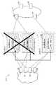
図1は、本発明の一実施形態に係る通信システムの概略構成を示す図である。通信システム1000は、OSI参照モデル(OSI reference model)のレイヤ3における仮想専用ネットワーク(以降「L3仮想閉域網」と呼ぶ)のサービス基盤として機能するシステムである。本実施形態の通信システム1000は、L3仮想閉域網を、IP−VPN(Internet Protocol Virtual Private Network)、より具体的には、MPLS−VPN(Multi-Protocol Label Switching Virtual Private Network)を利用することにより実現している。通信システム1000は、MPLSネットワーク3と、アクセスネットワーク4とを含む。A. Embodiment:
(Configuration of communication system)
FIG. 1 is a diagram showing a schematic configuration of a communication system according to an embodiment of the present invention. The
アクセスネットワーク4は、L3仮想閉域網サービスを利用するユーザ(クライアント)側に構築されているリングネットワークであり「アクセス網」として機能する。アクセスネットワーク4は、アクセスネットワーク4内に配置された複数の伝送装置40、41、42、43を含む。各伝送装置は、OSI参照モデルのレイヤ1,2に相当する物理層、データリンク層における伝送処理を行う周知の装置である。 The
MPLSネットワーク3は、MPLSを利用したラベルスイッチングにより仮想専用ネットワークを実現する「L3仮想閉域網」として機能する。MPLSネットワーク3は、L3仮想閉域網サービスを提供する通信事業者側に構築されているネットワークである。MPLSネットワーク3は、MPLSネットワーク3内に配置された複数の通信装置30、31、32、33と、MPLSネットワーク3のエッジに配置されたメイン通信装置10、11と、MPLSネットワーク3のエッジに配置されたDR通信装置20と、を含む。通信装置30、31、32、33はPルータとも呼ばれ、メイン通信装置10、11およびDR通信装置20はPEルータとも呼ばれる。 The MPLS
メイン通信装置10および11は、平常時におけるL3仮想閉域網サービスの提供を行うメインサイト1を構成している。メイン通信装置10は、現用系の通信装置(PEルータ)である。このため、図1の破線矢印に示すように、アクセスネットワーク4上にあるクライアント装置(図示省略)からのパケットは、メイン通信装置10を経由してMPLSネットワーク3へと転送される。一方、メイン通信装置11は、予備系の通信装置(PEルータ)である。すなわち、メイン通信装置11は、メイン通信装置10と同じ構成、同じIPアドレスを持ち、メイン通信装置10に障害が発生した場合においてメイン通信装置10に代替して動作する。このように、メイン通信装置11によってメインサイト1内でのPEルータの冗長化が図られている。なお、メイン通信装置11は省略してもよい。 The
DR通信装置20は、例えば災害等の発生に伴ってメインサイト1が使用不可能となった場合に、メインサイト1に代替して動作するDRサイト2を構成している。本実施形態のDR通信装置20は、後述の切替処理を実行することによって、メインサイト1の障害(換言すれば、メイン通信装置10および11の両方が使用不可能となったこと)を自動的に検知し、メインサイト1のメイン通信装置10、11に代替した転送処理を自動的に開始することができる。なお、DRサイト2はメインサイト1からの遠隔地に設けられることが多い。 The
メイン通信装置10、11と、DR通信装置20とには、MPLS−VPNを利用して、他の閉域OAと、監視用閉域SAとが設定されている。他の閉域OAは、L3仮想閉域網サービスのために用いられる閉域であり、サービス提供を受けるユーザ毎に設定されている。監視用閉域SAは、本実施形態の切替処理のために用いられる閉域(仮想専用ネットワーク)である。監視用閉域SAは「特定の閉域」として機能する。 In the
メイン通信装置10において、監視用閉域SAには、MPLS監視IF101とアクセス監視IF102とが設定されている。MPLS監視IF101は、アクセスネットワーク4に接続された「第1のインターフェース」であり、第1のアドレスが割り当てられている。アクセス監視IF102は、アクセスネットワーク4に接続された「第2のインターフェース」であり、第2のアドレスが割り当てられている。なお、MPLS監視IF101およびアクセス監視IF102を、アクセスネットワーク4に接続されたインターフェースとして設定することにより、アクセスネットワークの使用可否を検知することができる。同様に、メイン通信装置11において、監視用閉域SAには、MPLS監視IF111とアクセス監視IF112とが設定されている。MPLS監視IF111はMPLS監視IF101と同様の構成および機能を有し、アクセス監視IF112はアクセス監視IF102と同様の構成および機能を有する。 In the
DR通信装置20において、監視用閉域SAには、MPLS監視IF201とアクセス監視IF202とが設定されている。MPLS監視IF201は、MPLSネットワーク3に接続された「第3のインターフェース」であり、第3のアドレスが割り当てられている。アクセス監視IF202は、アクセスネットワーク4に接続された「第4のインターフェース」であり、第4のアドレスが割り当てられている。これら第1〜第4のアドレスは、それぞれ異なるIPアドレスである。なお、メイン通信装置10とDR通信装置20との間における経路情報のやりとりは、MPLS監視IF101とMPLS監視IF201とから、MPLSネットワーク3を経由して(具体的には、MPLSネットワーク3上の図示しないルートリフレクタを介して)行われる。メイン通信装置11についても同様である。また、図1の各通信装置において、他の閉域OAに設定されているインターフェースについては、図示を省略する。 In the
(DR通信装置の構成)
図2は、DR通信装置20の概略構成を示す図である。本実施形態のDR通信装置20は、後述の切替処理を実行することによって、メインサイト1の障害(換言すれば、メイン通信装置10および11の両方が使用不可能となったこと)を自動的に検知し、メインサイト1のメイン通信装置10、11に代替した転送処理を自動的に開始する。DR通信装置20は、請求項1における「通信装置」として機能する。(Configuration of DR communication device)
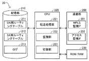
FIG. 2 is a diagram illustrating a schematic configuration of the
DR通信装置20は、記憶部210と、CPU220と、通信部200と、ROM/RAM230とを備えており、各部は図示しないバスにより相互に接続されている。 The
記憶部210は、ハードディスク、フラッシュメモリ、メモリカードなどで構成される。記憶部210には、OA用ルーティングテーブル211と、SA用ルーティングテーブル212と、ログ213とが記憶されている。OA用ルーティングテーブル211は、他の閉域OA(図1)用のルーティングテーブルである。SA用ルーティングテーブル212は、監視用閉域SA(図1)用のルーティングテーブルである。詳細は後述する。ログ213は、DR通信装置20の動作や状態が記録されるログである。 The
CPU220は、ROMに格納されているコンピュータプログラムをRAMに展開して実行することにより、DR通信装置20の各部を制御する。そのほか、CPU220は、転送処理部221、監視部222、切替部223としても機能する。 The
転送処理部221は、OA用ルーティングテーブル211に基づくデータ転送処理を実行することで他の閉域OA(図1)を形成する。また、転送処理部221は、SA用ルーティングテーブル212に基づくデータ転送処理を実行することで監視用閉域SA(図1)を形成する。なお、転送処理部221の機能の一部または全部は、CPU220とは別に設けられたASIC(Application Specific Integrated Circuit)等により実現されてもよい。例えば、転送処理部221のうち、OA用ルーティングテーブル211に基づくデータ転送処理はASICにより実現され、転送処理部221のうち、SA用ルーティングテーブル212に基づくデータ転送処理はCPU220により実現されてもよい。AISCを利用すれば、CPU220を利用した場合と比較して高速なデータ転送処理を実現できる。 The
監視部222は、後述の切替処理においてログ213を監視することで、メインサイト1の障害を検知する。切替部223は、後述の切替処理において、メインサイト1からDRサイト2への切り替えを実施する。 The
通信部200は、他の通信装置との間における通信を制御する。他の通信装置には、上述したメイン通信装置10、11、通信装置30〜33、伝送装置40〜43のほか、図1に記載しない他の装置が含まれていてもよい。通信部200には、監視用閉域SAに設定されている上述のMPLS監視IF201およびアクセス監視IF202と、他の閉域OAに設定されている複数のインターフェースとが含まれている。 The
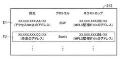
図3は、SA用ルーティングテーブル212の一部を示す図である。SA用ルーティングテーブル212には、エントリE1、E2の各経路情報が含まれている。なお、図3では、本発明に関連のない経路情報の図示を省略している。図3の「X」、「A」、「B」、「C」は任意の数字を意味する。 FIG. 3 is a diagram showing a part of the SA routing table 212. The SA routing table 212 includes path information for the entries E1 and E2. In FIG. 3, illustration of route information not related to the present invention is omitted. “X”, “A”, “B”, and “C” in FIG. 3 mean arbitrary numbers.
エントリE1は、DR通信装置20が、メイン通信装置10のMPLS監視IF101の経路情報を学習することによって得られた経路情報である。エントリE1は、アクセスネットワーク4上にあるIPアドレス「XX.XXX.XXX.AA/XX」が宛先である場合、転送処理のプロトコルとして「BGP」を使用し、次の転送先(ネクストホップ)として「XX.XXX.XXX.BB/XX」をアドレスに持つMPLS監視IF101を使用することが規定されている。 The entry E1 is route information obtained by the
一方、エントリE2は、切替処理においてメインサイト1の障害監視のために使用される静的ルート(スタティックルート)である。エントリE2は、任意のIPアドレス「XX.XXX.XXX.CC/XX」が宛先である場合、転送処理のプロトコルとして「Static」を使用し、次の転送先として「XX.XXX.XXX.BB/XX」をアドレスに持つMPLS監視IF101を使用することが規定されている。なお、エントリE2は上述の通り、メインサイト1の障害監視のために使用される経路情報である。このため、エントリE2の宛先は、通信システム1000上に存在しないダミーのIPアドレスであることが好ましい。 On the other hand, the entry E2 is a static route (static route) used for failure monitoring of the
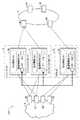
図4は、SA用ルーティングテーブル212のエントリE2について説明する図である。図4において破線の矢印で示すように、エントリE2には、DR通信装置20のMPLS監視IF201(第3のインターフェース)から、MPLSネットワーク3(L3仮想閉域網)を通過して、メイン通信装置10のMPLS監視IF101(第1のインターフェース)に割り当てられたIPアドレス(第1のアドレス)を経由する静的ルートが規定されていると言える。なお、図4では、メイン通信装置10と同様の構成を有する予備系のメイン通信装置11に対しても破線の矢印を付している。 FIG. 4 is a diagram illustrating the entry E2 of the SA routing table 212. As indicated by a broken arrow in FIG. 4, the entry E <b> 2 passes through the MPLS network 3 (L3 virtual closed network) from the MPLS monitoring IF 201 (third interface) of the
(切替処理)
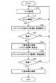
図5は、切替処理の手順を示すフローチャートである。切替処理は、DR通信装置20の監視部222と切替部223とが協働して実行される処理であり、DR通信装置20が動作している間は常に実行されている。(Switching process)
FIG. 5 is a flowchart showing the procedure of the switching process. The switching process is a process executed by the
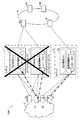
図6および図7は、切替処理のステップS10について説明する図である。図6に示すように、メインサイト1の両系(現用系および予備系)の通信装置、すなわち、メイン通信装置10とメイン通信装置11とが共に使用不可能となった場合を想定する。なお、メインサイト1のうち、現用系のメイン通信装置10のみが使用不可能となった場合は、予備系のメイン通信装置11が代わって動作するため、以下説明するDRサイト2への切り替えは行われない。 6 and 7 are diagrams for explaining step S10 of the switching process. As shown in FIG. 6, a case is assumed in which both systems (active system and standby system) of the
メインサイト1の両系の通信装置が共に使用不可能となった場合、メインサイト1の両系の通信装置に対して共にデータが到達しなくなるため、学習により得られるエントリE1の経路情報がSA用ルーティングテーブル212から削除される(図7:上段エントリE1)。そして、エントリE1の削除に伴い、エントリE2に規定された静的ルートの到達性も無くなる。このため、エントリE2の経路情報もSA用ルーティングテーブル212から削除される(図7:上段エントリE2)。この結果、DR通信装置20のログ213には、エントリE2に規定された静的ルートが削除された旨のメッセージErが記録される(図7:下段)。 If both communication systems at the
切替処理(図5)のステップS10において、監視部222はログ213を監視する。ステップS12において監視部222は、ログ213に静的ルートが削除された旨のメッセージEr(図7:下段)が記録されたか否かを判定する。メッセージErが無い場合、監視部222は、静的ルートが削除されていないと判定し(ステップS12:NO)、ログ213の監視を継続する。メッセージErがある場合、監視部222は、静的ルートが削除されたと判定し(ステップS12:YES)、処理をステップS20へ遷移させる。 In step S10 of the switching process (FIG. 5), the
ステップS10、S12によれば、監視部222は、ログ213の監視によって簡便に、静的ルートの削除を検出することができる。なお、監視部222は、ログ213を参照する以外の方法(例えば、SA用ルーティングテーブル212を検索する方法)によって、静的ルートの削除を検出してもよい。 According to steps S10 and S12, the
図8は、切替処理のステップS20について説明する図である。切替処理(図5)のステップS20において、切替部223は、メインサイト1のMPLS監視IF101、111に対する疎通確認を実施する。疎通確認は、例えば、MPLS監視IF101、111に割り当てられている第1のアドレス(XX.XXX.XXX.BB/XX)に対するpingコマンドを利用して実施できる。図8において一点鎖線の矢印で示すように、このpingコマンドは、DR通信装置20のMPLS監視IF201から、MPLSネットワーク3を経由して、メイン通信装置10、11へと送出される。 FIG. 8 is a diagram illustrating step S20 of the switching process. In step S <b> 20 of the switching process (FIG. 5), the
ステップS22において切替部223は、疎通したか否かを判定する。疎通した場合(ステップS22:YES)、切替部223は、静的ルートの削除はMPLS監視IF101、111のばたつきに起因するものであり、メインサイト1に障害が発生したわけではないと判定し、処理をステップS10へ遷移させてログ213の監視を継続させる。一方、疎通しない場合(ステップS22:NO)、切替部223は、メインサイト1に障害が発生したと判定し、処理をステップS24へ遷移させる。 In step S22, the
ステップS20、S22によれば、切替部223は、静的ルートの削除(メッセージEr)が、メインサイト1の障害に起因するものか否かを確認することができる。そして、切替部223は、疎通が確認できた場合は代替処理の実行を中止し、疎通が確認できなかった場合は代替処理を実行する。これにより、DR通信装置20は、メインサイト1の障害の検知を確実に行うと共に、代替処理が誤って実行されることを抑制することができる。なお、ステップS20、S22は省略してもよい。 According to steps S20 and S22, the
ステップS24において、切替部223は代替処理を開始する。代替処理とは、DR通信装置20が、メイン通信装置10、11に代わって動作するための「一連の処理」である。まず、切替部223は、アクセス監視IF202が所属しているインターフェース(親であるインターフェース)を停止状態から起動させる。その後、切替部223は、アクセス監視IF202や、他の閉域OAに設定されている各インターフェースを有効化する。有効化後、切替部223は、処理をステップS30へ遷移させる。なお、ステップS24では、上述した以外の種々の処理が実行されてよい。 In step S24, the
図9は、切替処理のステップS30について説明する図である。切替処理(図5)のステップS30において、切替部223は、メインサイト1のアクセス監視IF102、112に対する疎通確認を実施する。疎通確認は、例えば、アクセス監視IF102、112に割り当てられている第2のアドレスに対するpingコマンドを利用して実施できる。図9において一点鎖線の矢印で示すように、このpingコマンドは、DR通信装置20のアクセス監視IF202から、アクセスネットワーク4を経由して、メイン通信装置10、11へと送出される。 FIG. 9 is a diagram illustrating step S30 of the switching process. In step S <b> 30 of the switching process (FIG. 5), the
ステップS32において切替部223は、疎通したか否かを判定する。疎通した場合(ステップS32:YES)、切替部223は、メインサイト1が復旧した(メイン通信装置10、11が使用可能となった)と判定し、代替処理を中止する。切替部223は、代替処理の中止と共に切戻し処理(DR通信装置20を待機状態へと戻す処理)を実行してもよい。その後、切替部223は、処理をステップS10へ遷移させ、ログ213の監視を継続させる。一方、疎通しない場合(ステップS32:NO)、切替部223は、メインサイト1の障害が継続していると判定し、処理をステップS34へ遷移させる。 In step S32, the
図10は、切替処理のステップS34について説明する図である。ステップS34において切替部223は、引き続き、代替処理(DR通信装置20がメイン通信装置10、11に代わって動作するための一連の処理)の実行を継続する。これにより、図10の破線矢印に示すように、アクセスネットワーク4上にあるクライアント装置(図示省略)からのパケットは、DRサイト2のDR通信装置20を経由して、MPLSネットワーク3へと転送される。 FIG. 10 is a diagram illustrating step S34 of the switching process. In step S <b> 34, the
ステップS30、S32によれば、切替部223は、アクセスネットワーク4の側から、メインサイト1の状態を再度確認することができる。そして、切替部223は、疎通が確認できた場合は代替処理の実行を中止し、疎通が確認できなかった場合は代替処理を継続する(ステップS34)。これにより、DR通信装置20は、メインサイト1の障害の継続を確認すると共に、代替処理が誤って継続されることを抑制することができる。なお、ステップS30、S32は省略してもよい。また、ステップS34以降にも定期的に、ステップS30、S32と同じ処理が繰り返されてもよい。 According to steps S30 and S32, the
以上説明した通り、本発明によれば、DRサイトの通信装置(DR通信装置20)は、特定の閉域(監視用閉域SA)に属する第1のインターフェース(MPLS監視IF101、111)に割り当てられた第1のアドレス(XX.XXX.XXX.BB/XX)を経由する静的ルート(SA用ルーティングテーブル212のエントリE2)の削除をもって、メインサイト1の通信装置(メイン通信装置10、11)がダウンしたと判定し、メインサイト1からDRサイト2への切り替えを実施する(図5:ステップS24)。すなわち、本発明によれば、DRサイトの通信装置(DR通信装置20)は、閉域の設定、ルーティングテーブルにおける静的ルートの設定、ルーティングテーブルの状態監視といった、汎用的な技術を利用することで、メインサイト1の通信装置がダウンしたことを知ることができる。この結果、メインサイト1の通信装置(メイン通信装置10、11)の提供ベンダと、DRサイト2の通信装置(DR通信装置20)の提供ベンダとが異なる場合(マルチベンダな環境である場合)においても、メインサイト1とDRサイト2の切り替えを正常に実施することができる。 As described above, according to the present invention, the DR site communication device (DR communication device 20) is assigned to the first interface (MPLS monitoring IF 101, 111) belonging to a specific closed area (monitoring closed area SA). When the static route (entry E2 in the SA routing table 212) via the first address (XX.XXX.XXX.BB/XX) is deleted, the communication device (
B.変形例:
上述した各実施態様において、ハードウェアによって実現されるとした構成の一部をソフトウェアに置き換えるようにしてもよく、逆に、ソフトウェアによって実現されるとした構成の一部をハードウェアに置き換えるようにしてもよい。その他、以下のような変形も可能である。B. Variation:
In each of the above-described embodiments, a part of the configuration realized by hardware may be replaced by software, and conversely, a part of the configuration realized by software may be replaced by hardware. May be. In addition, the following modifications are possible.
上記実施形態では、メイン通信装置10、11、DR通信装置20は、いずれも、装置として実在する、いわゆる「物理ルータ」として説明した。しかし、メイン通信装置10、11、DR通信装置20のうちの少なくとも一部は、仮想的にルーティング機能を提供する、いわゆる「仮想ルータ」として構成されてもよい。仮想ルータの構成は、ハードウェア型、ソフトウェア型、分散エッジ型、種々採用できる。 In the above-described embodiment, the
上記実施形態では、L3仮想閉域網を、MPLS−VPNを利用することにより実現するとしたが、MPLS−VPNにおいてEVPN L3を利用することにより実現してもよい。 In the above embodiment, the L3 virtual closed network is realized by using MPLS-VPN, but may be realized by using EVPN L3 in MPLS-VPN.
上記実施形態では、メインサイト1における装置構成は、現用系と予備系の2台構成としたが、種々の変更が可能である。また、DRサイト2における装置構成についても、現用系の1台構成としたが、種々の変更が可能である。 In the above-described embodiment, the apparatus configuration at the
本発明を諸図面や実施例に基づき説明してきたが、当業者であれば本開示に基づき種々の変形や修正を行うことが容易であることに注意されたい。従って、これらの変形や修正は本発明の範囲に含まれることに留意されたい。例えば、各手段、各ステップ等に含まれる機能等は論理的に矛盾しないように再配置可能であり、複数の手段やステップ等を1つに組み合わせたり、或いは分割したりすることが可能である。また、上記実施の形態に示す構成を適宜組み合わせることとしてもよい。 Although the present invention has been described based on the drawings and examples, it should be noted that those skilled in the art can easily make various modifications and corrections based on the present disclosure. Therefore, it should be noted that these variations and modifications are included in the scope of the present invention. For example, the functions included in each means, each step, etc. can be rearranged so that there is no logical contradiction, and a plurality of means, steps, etc. can be combined or divided into one. . The structures described in the above embodiments may be combined as appropriate.
1…メインサイト
2…DRサイト
3…MPLSネットワーク
4…アクセスネットワーク
10…メイン通信装置
11…メイン通信装置
20…DR通信装置
30…通信装置
40…伝送装置
101…MPLS監視IF
102…アクセス監視IF
111…MPLS監視IF
112…アクセス監視IF
200…通信部
201…MPLS監視IF
202…アクセス監視IF
210…記憶部
211…OA用ルーティングテーブル
212…SA用ルーティングテーブル
213…ログ
220…CPU
221…転送処理部
222…監視部
223…切替部
230…ROM/RAM
1000…通信システム
OA…閉域
SA…監視用閉域DESCRIPTION OF
102 ... Access monitoring IF
111 ... MPLS monitoring IF
112 ... Access monitoring IF
200: Communication unit 201: MPLS monitoring IF
202 ... access monitoring IF
210 ...
221:
1000: Communication system OA ... Closed area SA ... Closed area for monitoring
Claims (9)
Translated fromJapanese特定の閉域用のルーティングテーブルであって、前記L3仮想閉域網を通過し、メインサイトの通信装置において前記特定の閉域に属する第1のインターフェースに割り当てられた第1のアドレスを経由する静的ルートを含むルーティングテーブルが記憶された記憶部と、
前記静的ルートの削除を監視する監視部と、
前記静的ルートの削除を契機として、前記通信装置が、前記メインサイトの通信装置に代替して動作するための一連の処理を実行する切替部と、
を備えるものであって、前記切替部は、
前記静的ルートの削除後、前記第1のアドレスに対する疎通を確認し、
前記疎通が確認できた場合は、前記一連の処理の実行を中止し、
前記疎通が確認できなかった場合は、前記一連の処理を実行する、通信装置。A communication device arranged at the edge of the L3 virtual closed network at the DR site,
A routing table for a specific closed area, passing through the L3 virtual closed network, and a static route passing through a first address assigned to a first interface belonging to the specific closed area in a communication device at a main site A storage unit storing a routing table including;
A monitoring unit for monitoring the deletion of the static route;
When the static route is deleted, the communication device executes a series of processes for operating in place of the main site communication device, and a switching unit,
Theswitching unit includes:
After deleting the static route, confirm communication with the first address;
When the communication is confirmed, the execution of the series of processes is stopped,
A communication devicethat executes the series of processes when the communication cannot be confirmed .
前記一連の処理は、前記通信装置において、前記L3仮想閉域網の外側にあるアクセス網に接続されたインターフェースを有効にする処理を含み、
前記切替部は、
前記有効にする処理の終了後、前記メインサイトの通信装置において前記アクセス網に接続されると共に前記特定の閉域に属する第2のインターフェースに割り当てられた第2のアドレスに対する疎通を確認し、
前記疎通が確認できた場合は、前記一連の処理の実行を中止し、
前記疎通が確認できなかった場合は、前記一連の処理を継続する、通信装置。The communication device according to claim 1,
The series of processes includes a process of enabling an interface connected to an access network outside the L3 virtual closed network in the communication device,
The switching unit is
After completion of the enabling process, the main site communication device is connected to the access network and confirms communication with the second address assigned to the second interface belonging to the specific closed area,
When the communication is confirmed, the execution of the series of processes is stopped,
A communication device that continues the series of processes when the communication cannot be confirmed.
前記監視部は、前記ルーティングテーブルの状態を記録したログを監視することにより、前記静的ルートの削除を監視する、通信装置。A communication device according to claim 1 or 2, wherein
The communication unit is configured to monitor deletion of the static route by monitoring a log in which the state of the routing table is recorded.
前記L3仮想閉域網を通過し、メインサイトの通信装置において特定の閉域に属する第1のインターフェースに割り当てられた第1のアドレスを経由する静的ルートの削除を監視する工程と、
前記静的ルートの削除を契機として、前記装置が、前記メインサイトの通信装置に代替して動作するための一連の処理を実行する工程と、前記実行する工程は、
前記静的ルートの削除後、前記第1のアドレスに対する疎通を確認し、
前記疎通が確認できた場合は、前記一連の処理の実行を中止し、
前記疎通が確認できなかった場合は、前記一連の処理を実行する通信方法。A communication method in a device arranged at an edge of an L3 virtual closed network in a DR site,
Monitoring the deletion of a static route that passes through the L3 virtual closed network and passes through a first address assigned to a first interface belonging to a specific closed area in a communication device at a main site;
In response to the deletion of the static route, the step of executing a series of processes for the device to operate in place of the communication device of the main site,
After deleting the static route, confirm communication with the first address;
When the communication is confirmed, the execution of the series of processes is stopped,
A communication methodfor executing the series of processes when the communication cannot be confirmed .
前記L3仮想閉域網を通過し、メインサイトの通信装置において特定の閉域に属する第1のインターフェースに割り当てられた第1のアドレスを経由する静的ルートの削除を監視する機能と、
前記静的ルートの削除を契機として、前記装置が、前記メインサイトの通信装置に代替して動作するための一連の処理を実行する機能と、を備えるものであって、前記実行する機能は、
前記静的ルートの削除後、前記第1のアドレスに対する疎通を確認し、
前記疎通が確認できた場合は、前記一連の処理の実行を中止し、
前記疎通が確認できなかった場合は、前記一連の処理を実行するコンピュータプログラム。A computer program executed in a device arranged at an edge of an L3 virtual closed network in a DR site,
A function of monitoring deletion of a static route that passes through the L3 virtual closed network and passes through a first address assigned to a first interface belonging to a specific closed area in a communication device at a main site;
Triggered by the deletion of the static route, the device includes a function of executing a series of processes for operating instead of the communication device of the main site, and the function to be executedis
After deleting the static route, confirm communication with the first address;
When the communication is confirmed, the execution of the series of processes is stopped,
A computer programthat executes the series of processes when the communication cannot be confirmed .
メインサイトにおいて、L3仮想閉域網のエッジに配置されるメイン通信装置と、
DRサイトにおいて、前記L3仮想閉域網のエッジに配置されるDR通信装置と、
を備え、
前記メイン通信装置は、
前記L3仮想閉域網に接続されると共に特定の閉域に属し、第1のアドレスが割り当てられた第1のインターフェースと、
前記L3仮想閉域網の外側にあるアクセス網に接続されると共に前記特定の閉域に属し、第2のアドレスが割り当てられた第2のインターフェースと、
を備え、
前記DR通信装置は、
前記L3仮想閉域網に接続されると共に前記特定の閉域に属し、第3のアドレスが割り当てられた第3のインターフェースと、
前記アクセス網に接続されると共に前記特定の閉域に属し、第4のアドレスが割り当てられた第4のインターフェースと、
前記特定の閉域用のルーティングテーブルであって、前記第3のインターフェースから前記L3仮想閉域網を通過し、前記第1のアドレスを経由する静的ルートを含むルーティングテーブルが記憶された記憶部と、
前記静的ルートの削除を監視する監視部と、
前記静的ルートの削除を契機として、前記DR通信装置が、前記メイン通信装置に代替して動作するための一連の処理を実行する切替部と、前記DR通信装置の前記切替部は、
前記静的ルートの削除後、前記第1のアドレスに対する疎通を確認し、
前記疎通が確認できた場合は、前記一連の処理の実行を中止し、
前記疎通が確認できなかった場合は、前記一連の処理を実行するものである、通信システム。A communication system,
At the main site, a main communication device arranged at the edge of the L3 virtual closed network,
A DR communication device arranged at an edge of the L3 virtual closed network at a DR site;
With
The main communication device is
A first interface connected to the L3 virtual closed network and belonging to a specific closed area and assigned a first address;
A second interface connected to an access network outside the L3 virtual closed network and belonging to the specific closed area and assigned a second address;
With
The DR communication device
A third interface connected to the L3 virtual closed network and belonging to the specific closed area and assigned with a third address;
A fourth interface connected to the access network and belonging to the specific closed area and assigned a fourth address;
A storage unit storing a routing table for a specific closed area, the routing table including a static route passing through the L3 virtual closed network from the third interface and passing through the first address;
A monitoring unit for monitoring the deletion of the static route;
In response to the deletion of the static route, the DR communication device executes a series of processes for operating instead of the main communication device, and the switching unit of theDR communication device includes:
After deleting the static route, confirm communication with the first address;
When the communication is confirmed, the execution of the series of processes is stopped,
A communication systemthat executes the series of processes when the communication cannot be confirmed .
前記DR通信装置の前記切替部は、
前記静的ルートの削除後、前記第1のアドレスに対する疎通を確認し、
前記疎通が確認できた場合は、前記一連の処理の実行を中止し、
前記疎通が確認できなかった場合は、前記一連の処理を実行する、通信システム。The communication system according to claim6 ,
The switching unit of the DR communication device includes:
After deleting the static route, confirm communication with the first address;
When the communication is confirmed, the execution of the series of processes is stopped,
A communication system that executes the series of processes when the communication cannot be confirmed.
前記一連の処理は、前記第4のインターフェースを有効にする処理を含み、
前記DR通信装置の前記切替部は、
前記有効にする処理の終了後、前記第2のアドレスに対する疎通を確認し、
前記疎通が確認できた場合は、前記一連の処理の実行を中止し、
前記疎通が確認できなかった場合は、前記一連の処理を継続する、通信システム。The communication system according to claim6 or7 ,
The series of processes includes a process of enabling the fourth interface,
The switching unit of the DR communication device includes:
After completion of the enabling process, confirm communication with the second address,
When the communication is confirmed, the execution of the series of processes is stopped,
A communication system that continues the series of processes when the communication cannot be confirmed.
前記DR通信装置の前記監視部は、前記ルーティングテーブルの状態を記録したログを監視することにより、前記静的ルートの削除を監視する、通信システム。
A communication system according to any one of claims6 to8 , comprising:
The communication unit, wherein the monitoring unit of the DR communication device monitors the deletion of the static route by monitoring a log recording the state of the routing table.
Priority Applications (1)
| Application Number | Priority Date | Filing Date | Title |
|---|---|---|---|
| JP2017170262AJP6490167B2 (en) | 2017-09-05 | 2017-09-05 | COMMUNICATION DEVICE, COMMUNICATION METHOD, COMPUTER PROGRAM, AND COMMUNICATION SYSTEM |
Applications Claiming Priority (1)
| Application Number | Priority Date | Filing Date | Title |
|---|---|---|---|
| JP2017170262AJP6490167B2 (en) | 2017-09-05 | 2017-09-05 | COMMUNICATION DEVICE, COMMUNICATION METHOD, COMPUTER PROGRAM, AND COMMUNICATION SYSTEM |
Publications (2)
| Publication Number | Publication Date |
|---|---|
| JP2019047396A JP2019047396A (en) | 2019-03-22 |
| JP6490167B2true JP6490167B2 (en) | 2019-03-27 |
Family
ID=65814898
Family Applications (1)
| Application Number | Title | Priority Date | Filing Date |
|---|---|---|---|
| JP2017170262AActiveJP6490167B2 (en) | 2017-09-05 | 2017-09-05 | COMMUNICATION DEVICE, COMMUNICATION METHOD, COMPUTER PROGRAM, AND COMMUNICATION SYSTEM |
Country Status (1)
| Country | Link |
|---|---|
| JP (1) | JP6490167B2 (en) |
Families Citing this family (1)
| Publication number | Priority date | Publication date | Assignee | Title |
|---|---|---|---|---|
| CN112737942B (en)* | 2020-12-24 | 2022-06-03 | 土巴兔集团股份有限公司 | Service route switching method, device, equipment and medium |
Family Cites Families (4)
| Publication number | Priority date | Publication date | Assignee | Title |
|---|---|---|---|---|
| WO2008120267A1 (en)* | 2007-03-28 | 2008-10-09 | Fujitsu Limited | Edge node redundant system |
| JP4980971B2 (en)* | 2008-03-27 | 2012-07-18 | 株式会社野村総合研究所 | Route flapping prevention device, route flapping prevention router |
| JP5083432B2 (en)* | 2011-04-04 | 2012-11-28 | 富士通株式会社 | Route control apparatus and route control method |
| JP5941404B2 (en)* | 2012-12-28 | 2016-06-29 | 株式会社日立製作所 | Communication system, path switching method, and communication apparatus |
- 2017
- 2017-09-05JPJP2017170262Apatent/JP6490167B2/enactiveActive
Also Published As
| Publication number | Publication date |
|---|---|
| JP2019047396A (en) | 2019-03-22 |
Similar Documents
| Publication | Publication Date | Title |
|---|---|---|
| AU2004306913B2 (en) | Redundant routing capabilities for a network node cluster | |
| CN110113259B (en) | Path state notification method, path switching method, forwarding equipment and system | |
| US20060087962A1 (en) | Fault tolerant network architecture | |
| WO2014087850A1 (en) | Automatic-fault-handling cache system, fault-handling processing method for cache server, and cache manager | |
| CN101588302B (en) | Method and apparatus for updating router | |
| CN104168193A (en) | Virtual router redundancy protocol fault detection method and router equipment | |
| US7710899B1 (en) | System and method for speeding border gateway protocol graceful restart | |
| CN105939254B (en) | The method and device of VRRP backup group state switching | |
| JP4620019B2 (en) | Network monitoring apparatus, network monitoring method, and computer program | |
| JP4922267B2 (en) | Gateway device, route control method and program thereof | |
| WO2017036165A1 (en) | Link fault detection method and apparatus | |
| CN103348722B (en) | Systems and methods for providing communication connection resiliency | |
| JP6524817B2 (en) | Route control apparatus, route control system and route control method | |
| JP6490167B2 (en) | COMMUNICATION DEVICE, COMMUNICATION METHOD, COMPUTER PROGRAM, AND COMMUNICATION SYSTEM | |
| US11258700B1 (en) | Enhanced messaging for backup state status notifications in communications networks | |
| CN110535947A (en) | A kind of memory device set group configuration node switching method, device and equipment | |
| CN102932249A (en) | Method and device for transmitting virtual router redundancy protocol (VRRP) message | |
| WO2018223991A1 (en) | Method and system for switching between active bng and standby bng, and bng | |
| JP4133738B2 (en) | High-speed network address takeover method, network device, and program | |
| CN101651560B (en) | Two-way routing network and reliability supporting method | |
| CN108259325A (en) | Route maintenance method and routing device | |
| WO2016202015A1 (en) | Method and apparatus for protecting active and standby access network elements in data communications network | |
| CN116155795A (en) | Route updating method and device | |
| JP4378205B2 (en) | Blade type network relay device | |
| US11374849B1 (en) | High availability router switchover decision using monitoring and policies |
Legal Events
| Date | Code | Title | Description |
|---|---|---|---|
| A521 | Request for written amendment filed | Free format text:JAPANESE INTERMEDIATE CODE: A523 Effective date:20190108 | |
| TRDD | Decision of grant or rejection written | ||
| A01 | Written decision to grant a patent or to grant a registration (utility model) | Free format text:JAPANESE INTERMEDIATE CODE: A01 Effective date:20190212 | |
| A61 | First payment of annual fees (during grant procedure) | Free format text:JAPANESE INTERMEDIATE CODE: A61 Effective date:20190226 | |
| R150 | Certificate of patent or registration of utility model | Ref document number:6490167 Country of ref document:JP Free format text:JAPANESE INTERMEDIATE CODE: R150 | |
| S531 | Written request for registration of change of domicile | Free format text:JAPANESE INTERMEDIATE CODE: R313531 | |
| R350 | Written notification of registration of transfer | Free format text:JAPANESE INTERMEDIATE CODE: R350 | |
| R250 | Receipt of annual fees | Free format text:JAPANESE INTERMEDIATE CODE: R250 | |
| R250 | Receipt of annual fees | Free format text:JAPANESE INTERMEDIATE CODE: R250 |