JP6489422B2 - Assist wear, assist wear operating method, and control program - Google Patents
Assist wear, assist wear operating method, and control programDownload PDFInfo
- Publication number
- JP6489422B2 JP6489422B2JP2015014663AJP2015014663AJP6489422B2JP 6489422 B2JP6489422 B2JP 6489422B2JP 2015014663 AJP2015014663 AJP 2015014663AJP 2015014663 AJP2015014663 AJP 2015014663AJP 6489422 B2JP6489422 B2JP 6489422B2
- Authority
- JP
- Japan
- Prior art keywords
- actuator
- wear
- assist
- fit
- actuators
- Prior art date
- Legal status (The legal status is an assumption and is not a legal conclusion. Google has not performed a legal analysis and makes no representation as to the accuracy of the status listed.)
- Active
Links
Images


Classifications
- A—HUMAN NECESSITIES
- A41—WEARING APPAREL
- A41D—OUTERWEAR; PROTECTIVE GARMENTS; ACCESSORIES
- A41D1/00—Garments
- A41D1/002—Garments adapted to accommodate electronic equipment
- A—HUMAN NECESSITIES
- A61—MEDICAL OR VETERINARY SCIENCE; HYGIENE
- A61B—DIAGNOSIS; SURGERY; IDENTIFICATION
- A61B5/00—Measuring for diagnostic purposes; Identification of persons
- A61B5/103—Measuring devices for testing the shape, pattern, colour, size or movement of the body or parts thereof, for diagnostic purposes
- A61B5/11—Measuring movement of the entire body or parts thereof, e.g. head or hand tremor or mobility of a limb
- A61B5/1107—Measuring contraction of parts of the body, e.g. organ or muscle
- A—HUMAN NECESSITIES
- A61—MEDICAL OR VETERINARY SCIENCE; HYGIENE
- A61B—DIAGNOSIS; SURGERY; IDENTIFICATION
- A61B5/00—Measuring for diagnostic purposes; Identification of persons
- A61B5/68—Arrangements of detecting, measuring or recording means, e.g. sensors, in relation to patient
- A61B5/6801—Arrangements of detecting, measuring or recording means, e.g. sensors, in relation to patient specially adapted to be attached to or worn on the body surface
- A61B5/6802—Sensor mounted on worn items
- A61B5/6804—Garments; Clothes
- A—HUMAN NECESSITIES
- A61—MEDICAL OR VETERINARY SCIENCE; HYGIENE
- A61F—FILTERS IMPLANTABLE INTO BLOOD VESSELS; PROSTHESES; DEVICES PROVIDING PATENCY TO, OR PREVENTING COLLAPSING OF, TUBULAR STRUCTURES OF THE BODY, e.g. STENTS; ORTHOPAEDIC, NURSING OR CONTRACEPTIVE DEVICES; FOMENTATION; TREATMENT OR PROTECTION OF EYES OR EARS; BANDAGES, DRESSINGS OR ABSORBENT PADS; FIRST-AID KITS
- A61F2/00—Filters implantable into blood vessels; Prostheses, i.e. artificial substitutes or replacements for parts of the body; Appliances for connecting them with the body; Devices providing patency to, or preventing collapsing of, tubular structures of the body, e.g. stents
- A61F2/50—Prostheses not implantable in the body
- A—HUMAN NECESSITIES
- A61—MEDICAL OR VETERINARY SCIENCE; HYGIENE
- A61H—PHYSICAL THERAPY APPARATUS, e.g. DEVICES FOR LOCATING OR STIMULATING REFLEX POINTS IN THE BODY; ARTIFICIAL RESPIRATION; MASSAGE; BATHING DEVICES FOR SPECIAL THERAPEUTIC OR HYGIENIC PURPOSES OR SPECIFIC PARTS OF THE BODY
- A61H1/00—Apparatus for passive exercising; Vibrating apparatus; Chiropractic devices, e.g. body impacting devices, external devices for briefly extending or aligning unbroken bones
- A61H1/02—Stretching or bending or torsioning apparatus for exercising
- A61H1/0237—Stretching or bending or torsioning apparatus for exercising for the lower limbs
- A61H1/0244—Hip
- A—HUMAN NECESSITIES
- A61—MEDICAL OR VETERINARY SCIENCE; HYGIENE
- A61H—PHYSICAL THERAPY APPARATUS, e.g. DEVICES FOR LOCATING OR STIMULATING REFLEX POINTS IN THE BODY; ARTIFICIAL RESPIRATION; MASSAGE; BATHING DEVICES FOR SPECIAL THERAPEUTIC OR HYGIENIC PURPOSES OR SPECIFIC PARTS OF THE BODY
- A61H1/00—Apparatus for passive exercising; Vibrating apparatus; Chiropractic devices, e.g. body impacting devices, external devices for briefly extending or aligning unbroken bones
- A61H1/02—Stretching or bending or torsioning apparatus for exercising
- A61H1/0274—Stretching or bending or torsioning apparatus for exercising for the upper limbs
- A61H1/0277—Elbow
- A—HUMAN NECESSITIES
- A61—MEDICAL OR VETERINARY SCIENCE; HYGIENE
- A61H—PHYSICAL THERAPY APPARATUS, e.g. DEVICES FOR LOCATING OR STIMULATING REFLEX POINTS IN THE BODY; ARTIFICIAL RESPIRATION; MASSAGE; BATHING DEVICES FOR SPECIAL THERAPEUTIC OR HYGIENIC PURPOSES OR SPECIFIC PARTS OF THE BODY
- A61H1/00—Apparatus for passive exercising; Vibrating apparatus; Chiropractic devices, e.g. body impacting devices, external devices for briefly extending or aligning unbroken bones
- A61H1/02—Stretching or bending or torsioning apparatus for exercising
- A61H1/0274—Stretching or bending or torsioning apparatus for exercising for the upper limbs
- A61H1/0285—Hand
- A61H1/0288—Fingers
- A—HUMAN NECESSITIES
- A61—MEDICAL OR VETERINARY SCIENCE; HYGIENE
- A61H—PHYSICAL THERAPY APPARATUS, e.g. DEVICES FOR LOCATING OR STIMULATING REFLEX POINTS IN THE BODY; ARTIFICIAL RESPIRATION; MASSAGE; BATHING DEVICES FOR SPECIAL THERAPEUTIC OR HYGIENIC PURPOSES OR SPECIFIC PARTS OF THE BODY
- A61H3/00—Appliances for aiding patients or disabled persons to walk about
- A61H2003/007—Appliances for aiding patients or disabled persons to walk about secured to the patient, e.g. with belts
- A—HUMAN NECESSITIES
- A61—MEDICAL OR VETERINARY SCIENCE; HYGIENE
- A61H—PHYSICAL THERAPY APPARATUS, e.g. DEVICES FOR LOCATING OR STIMULATING REFLEX POINTS IN THE BODY; ARTIFICIAL RESPIRATION; MASSAGE; BATHING DEVICES FOR SPECIAL THERAPEUTIC OR HYGIENIC PURPOSES OR SPECIFIC PARTS OF THE BODY
- A61H2201/00—Characteristics of apparatus not provided for in the preceding codes
- A61H2201/01—Constructive details
- A61H2201/0173—Means for preventing injuries
- A61H2201/0184—Means for preventing injuries by raising an alarm
- A—HUMAN NECESSITIES
- A61—MEDICAL OR VETERINARY SCIENCE; HYGIENE
- A61H—PHYSICAL THERAPY APPARATUS, e.g. DEVICES FOR LOCATING OR STIMULATING REFLEX POINTS IN THE BODY; ARTIFICIAL RESPIRATION; MASSAGE; BATHING DEVICES FOR SPECIAL THERAPEUTIC OR HYGIENIC PURPOSES OR SPECIFIC PARTS OF THE BODY
- A61H2201/00—Characteristics of apparatus not provided for in the preceding codes
- A61H2201/02—Characteristics of apparatus not provided for in the preceding codes heated or cooled
- A61H2201/0207—Characteristics of apparatus not provided for in the preceding codes heated or cooled heated
- A—HUMAN NECESSITIES
- A61—MEDICAL OR VETERINARY SCIENCE; HYGIENE
- A61H—PHYSICAL THERAPY APPARATUS, e.g. DEVICES FOR LOCATING OR STIMULATING REFLEX POINTS IN THE BODY; ARTIFICIAL RESPIRATION; MASSAGE; BATHING DEVICES FOR SPECIAL THERAPEUTIC OR HYGIENIC PURPOSES OR SPECIFIC PARTS OF THE BODY
- A61H2201/00—Characteristics of apparatus not provided for in the preceding codes
- A61H2201/02—Characteristics of apparatus not provided for in the preceding codes heated or cooled
- A61H2201/0214—Characteristics of apparatus not provided for in the preceding codes heated or cooled cooled
- A—HUMAN NECESSITIES
- A61—MEDICAL OR VETERINARY SCIENCE; HYGIENE
- A61H—PHYSICAL THERAPY APPARATUS, e.g. DEVICES FOR LOCATING OR STIMULATING REFLEX POINTS IN THE BODY; ARTIFICIAL RESPIRATION; MASSAGE; BATHING DEVICES FOR SPECIAL THERAPEUTIC OR HYGIENIC PURPOSES OR SPECIFIC PARTS OF THE BODY
- A61H2201/00—Characteristics of apparatus not provided for in the preceding codes
- A61H2201/02—Characteristics of apparatus not provided for in the preceding codes heated or cooled
- A61H2201/0221—Mechanism for heating or cooling
- A61H2201/0228—Mechanism for heating or cooling heated by an electric resistance element
- A—HUMAN NECESSITIES
- A61—MEDICAL OR VETERINARY SCIENCE; HYGIENE
- A61H—PHYSICAL THERAPY APPARATUS, e.g. DEVICES FOR LOCATING OR STIMULATING REFLEX POINTS IN THE BODY; ARTIFICIAL RESPIRATION; MASSAGE; BATHING DEVICES FOR SPECIAL THERAPEUTIC OR HYGIENIC PURPOSES OR SPECIFIC PARTS OF THE BODY
- A61H2201/00—Characteristics of apparatus not provided for in the preceding codes
- A61H2201/12—Driving means
- A61H2201/1207—Driving means with electric or magnetic drive
- A—HUMAN NECESSITIES
- A61—MEDICAL OR VETERINARY SCIENCE; HYGIENE
- A61H—PHYSICAL THERAPY APPARATUS, e.g. DEVICES FOR LOCATING OR STIMULATING REFLEX POINTS IN THE BODY; ARTIFICIAL RESPIRATION; MASSAGE; BATHING DEVICES FOR SPECIAL THERAPEUTIC OR HYGIENIC PURPOSES OR SPECIFIC PARTS OF THE BODY
- A61H2201/00—Characteristics of apparatus not provided for in the preceding codes
- A61H2201/12—Driving means
- A61H2201/1238—Driving means with hydraulic or pneumatic drive
- A—HUMAN NECESSITIES
- A61—MEDICAL OR VETERINARY SCIENCE; HYGIENE
- A61H—PHYSICAL THERAPY APPARATUS, e.g. DEVICES FOR LOCATING OR STIMULATING REFLEX POINTS IN THE BODY; ARTIFICIAL RESPIRATION; MASSAGE; BATHING DEVICES FOR SPECIAL THERAPEUTIC OR HYGIENIC PURPOSES OR SPECIFIC PARTS OF THE BODY
- A61H2201/00—Characteristics of apparatus not provided for in the preceding codes
- A61H2201/16—Physical interface with patient
- A61H2201/1602—Physical interface with patient kind of interface, e.g. head rest, knee support or lumbar support
- A61H2201/165—Wearable interfaces
- A—HUMAN NECESSITIES
- A61—MEDICAL OR VETERINARY SCIENCE; HYGIENE
- A61H—PHYSICAL THERAPY APPARATUS, e.g. DEVICES FOR LOCATING OR STIMULATING REFLEX POINTS IN THE BODY; ARTIFICIAL RESPIRATION; MASSAGE; BATHING DEVICES FOR SPECIAL THERAPEUTIC OR HYGIENIC PURPOSES OR SPECIFIC PARTS OF THE BODY
- A61H2201/00—Characteristics of apparatus not provided for in the preceding codes
- A61H2201/50—Control means thereof
- A61H2201/5002—Means for controlling a set of similar massage devices acting in sequence at different locations on a patient
- A—HUMAN NECESSITIES
- A61—MEDICAL OR VETERINARY SCIENCE; HYGIENE
- A61H—PHYSICAL THERAPY APPARATUS, e.g. DEVICES FOR LOCATING OR STIMULATING REFLEX POINTS IN THE BODY; ARTIFICIAL RESPIRATION; MASSAGE; BATHING DEVICES FOR SPECIAL THERAPEUTIC OR HYGIENIC PURPOSES OR SPECIFIC PARTS OF THE BODY
- A61H2201/00—Characteristics of apparatus not provided for in the preceding codes
- A61H2201/50—Control means thereof
- A61H2201/5007—Control means thereof computer controlled
- A61H2201/501—Control means thereof computer controlled connected to external computer devices or networks
- A—HUMAN NECESSITIES
- A61—MEDICAL OR VETERINARY SCIENCE; HYGIENE
- A61H—PHYSICAL THERAPY APPARATUS, e.g. DEVICES FOR LOCATING OR STIMULATING REFLEX POINTS IN THE BODY; ARTIFICIAL RESPIRATION; MASSAGE; BATHING DEVICES FOR SPECIAL THERAPEUTIC OR HYGIENIC PURPOSES OR SPECIFIC PARTS OF THE BODY
- A61H2201/00—Characteristics of apparatus not provided for in the preceding codes
- A61H2201/50—Control means thereof
- A61H2201/5058—Sensors or detectors
- A61H2201/5061—Force sensors
- A—HUMAN NECESSITIES
- A61—MEDICAL OR VETERINARY SCIENCE; HYGIENE
- A61H—PHYSICAL THERAPY APPARATUS, e.g. DEVICES FOR LOCATING OR STIMULATING REFLEX POINTS IN THE BODY; ARTIFICIAL RESPIRATION; MASSAGE; BATHING DEVICES FOR SPECIAL THERAPEUTIC OR HYGIENIC PURPOSES OR SPECIFIC PARTS OF THE BODY
- A61H2201/00—Characteristics of apparatus not provided for in the preceding codes
- A61H2201/50—Control means thereof
- A61H2201/5058—Sensors or detectors
- A61H2201/5084—Acceleration sensors
- A—HUMAN NECESSITIES
- A61—MEDICAL OR VETERINARY SCIENCE; HYGIENE
- A61H—PHYSICAL THERAPY APPARATUS, e.g. DEVICES FOR LOCATING OR STIMULATING REFLEX POINTS IN THE BODY; ARTIFICIAL RESPIRATION; MASSAGE; BATHING DEVICES FOR SPECIAL THERAPEUTIC OR HYGIENIC PURPOSES OR SPECIFIC PARTS OF THE BODY
- A61H2230/00—Measuring physical parameters of the user
- A61H2230/08—Other bio-electrical signals
- A61H2230/085—Other bio-electrical signals used as a control parameter for the apparatus
- A—HUMAN NECESSITIES
- A61—MEDICAL OR VETERINARY SCIENCE; HYGIENE
- A61H—PHYSICAL THERAPY APPARATUS, e.g. DEVICES FOR LOCATING OR STIMULATING REFLEX POINTS IN THE BODY; ARTIFICIAL RESPIRATION; MASSAGE; BATHING DEVICES FOR SPECIAL THERAPEUTIC OR HYGIENIC PURPOSES OR SPECIFIC PARTS OF THE BODY
- A61H2230/00—Measuring physical parameters of the user
- A61H2230/60—Muscle strain, i.e. measured on the user, e.g. Electromyography [EMG]
- A61H2230/605—Muscle strain, i.e. measured on the user, e.g. Electromyography [EMG] used as a control parameter for the apparatus
Landscapes
- Health & Medical Sciences (AREA)
- Life Sciences & Earth Sciences (AREA)
- General Health & Medical Sciences (AREA)
- Veterinary Medicine (AREA)
- Animal Behavior & Ethology (AREA)
- Public Health (AREA)
- Physical Education & Sports Medicine (AREA)
- Rehabilitation Therapy (AREA)
- Pain & Pain Management (AREA)
- Epidemiology (AREA)
- Engineering & Computer Science (AREA)
- Heart & Thoracic Surgery (AREA)
- Biomedical Technology (AREA)
- Oral & Maxillofacial Surgery (AREA)
- Medical Informatics (AREA)
- Surgery (AREA)
- Biophysics (AREA)
- Pathology (AREA)
- Molecular Biology (AREA)
- Physics & Mathematics (AREA)
- Textile Engineering (AREA)
- Transplantation (AREA)
- Cardiology (AREA)
- Vascular Medicine (AREA)
- Dentistry (AREA)
- Physiology (AREA)
- Manipulator (AREA)
- Rehabilitation Tools (AREA)
- Massaging Devices (AREA)
Description
Translated fromJapanese本発明は、生体に装着して生体の発生力を補助して生体の動作を支援するアシストウェア、アシストウェアの作動方法、及び、制御プログラムに関する。The present invention assists wear wearing to the living body to assist the force generated living body to assist the operation of the living body,actuation how the assist hardware, and a control program.
従来、布等のメッシュ状の人体装着部を人体の膝などの関節部分に装着し、人体装着部に設けられたアクチュエータを駆動して人体の発生力を補助することにより、日常生活における動作を支援することができる人体運動補助装置が知られている(例えば、特許文献1参照。)。 Conventionally, a mesh-like human body wearing part such as a cloth is attached to a joint part such as a knee of a human body, and an actuator provided in the human body wearing part is driven to assist the human body's generated force, thereby enabling movement in daily life. A human body movement assisting device that can assist is known (for example, see Patent Document 1).
しかしながら、従来技術では、アシストウェアのフィット状態または装着位置を適切にするため、さらなる改善が必要であった。 However, in the prior art, further improvement is necessary in order to make the fit state or mounting position of the assist wear appropriate.
そこで、本開示は、より適切にアシスト力が生体に作用するアシストウェア、アシストウェアの作動方法、及び、制御プログラムを提供する。The present disclosure is more appropriately assisted hardware assist force acts on the living body,actuation how the assist hardware, and provides a control program.
本発明の一態様にかかるアシストウェアは、
生体の部位に装着されるアシストウェアであって、
前記部位に装着された場合において前記部位の筋肉の伸縮方向に沿って線状に複数本配置され、伸縮駆動して前記筋肉の動きをアシストするアシスト用アクチュエータと、
前記アシスト用アクチュエータと交差して線状に複数本配置され、伸縮駆動するフィット用アクチュエータと、
前記アシスト用アクチュエータの駆動と、前記フィット用アクチュエータの駆動とをそれぞれ制御する制御部と、
を備え、
前記制御部は、前記フィット用アクチュエータを駆動することによって前記フィット用アクチュエータを収縮させ、前記部位に前記アシスト用アクチュエータを密着固定し、前記フィット用アクチュエータを駆動することによって前記フィット用アクチュエータを伸張させ、前記密着固定を開放する、ものである。
Assist wear according to one aspect of the present invention is
Assist wear to be worn on the body part,
A plurality of linearly arranged along the direction of expansion and contraction of the muscles of the part when mounted on the part, and an assisting actuator that assists the movement of the muscle by extending and contracting,
A plurality of linear actuators that intersect with the assisting actuators and are driven to extend and contract, and
A control unit that controls driving of the assisting actuator and driving of the fitting actuator;
Equipped witha,
The control unit contracts the fit actuator by driving the fit actuator, closely contacts and fixes the assist actuator to the portion, and extends the fit actuator by driving the fit actuator. , it opens the tightly fixed, those.
本発明の前記一態様によれば、アシスト用アクチュエータからのアシスト力を、より適切に生体の筋肉などに作用させることが可能になる。 According to the one aspect of the present invention, the assist force from the assist actuator can be more appropriately applied to a living body muscle or the like.
以下に、本発明にかかる実施の形態を図面に基づいて詳細に説明する。 Embodiments according to the present invention will be described below in detail with reference to the drawings.
以下、図面を参照して本発明における実施形態を詳細に説明する前に、本発明の種々の態様について説明する。 DESCRIPTION OF EMBODIMENTS Hereinafter, various embodiments of the present invention will be described before detailed description of embodiments of the present invention with reference to the drawings.
本開示の第1の態様にかかるアシストウェアは、生体の部位に装着されるアシストウェアであって、
前記部位に装着された場合において前記部位の筋肉の伸縮方向に沿って線状に複数本配置され、伸縮駆動するアシスト用アクチュエータと、
前記アシスト用アクチュエータと交差して線状に複数本配置され、伸縮駆動するフィット用アクチュエータと、
前記アシスト用アクチュエータの駆動と、前記フィット用アクチュエータの駆動とをそれぞれ制御する制御部と、
を備える。The assist wear according to the first aspect of the present disclosure is assist wear attached to a part of a living body,
A plurality of assisting actuators that are arranged linearly along the direction of expansion and contraction of the muscles of the part when attached to the part, and that are driven to extend and contract,
A plurality of linear actuators that intersect with the assisting actuators and are driven to extend and contract, and
A control unit that controls driving of the assisting actuator and driving of the fitting actuator;
Is provided.
従来のアシストウェアのように、アシスト用アクチュエータを用いただけでは、アシスト用アクチュエータの伸縮過程でアシストウェアに偏ったしわが生じ、アシストウェアが人体にフィットしない場合が生じ得る。そのため、例えば、様々な体型の、人体に対応することは困難であり、アシストウェアのフィット状態又は装着位置が不適切になりやすく、アクチュエータによるアシスト力が十分に人体の筋肉に作用しなくなるという課題があった。 If only the assist actuator is used as in the conventional assist wear, wrinkles biased in the assist wear may occur during the expansion and contraction process of the assist actuator, and the assist wear may not fit the human body. Therefore, for example, it is difficult to deal with the human body of various body types, the fit state or wearing position of the assist wear tends to be inappropriate, and the assist force by the actuator does not sufficiently act on the human muscle was there.
本態様によると、アシスト用アクチュエータの他に、アシスト用アクチュエータと交差してフィット用アクチュエータを設けている。これにより、アシスト用アクチュエータを用いてアシストウェアを筋肉の伸縮方向に沿って伸縮させるだけではなく、フィット用アクチュエータを用いてアシスト用アクチュエータと交差する方向にアシストウェアを収縮させることができる。そのため、フィット用アクチュエータを用いてアシスト用アクチュエータの伸縮過程でアシストウェアに偏ったしわが生じるのを防ぎつつ、生体に、より適切にフィットした状態とすることができる。その結果、アシスト用アクチュエータからのアシスト力を、より適切に生体の筋肉に作用させることが可能になる。 According to this aspect, in addition to the assisting actuator, the fitting actuator is provided so as to intersect the assisting actuator. Thus, the assist wear can be contracted in the direction intersecting with the assist actuator using the fit actuator, as well as the assist wear using the assist actuator. For this reason, the fitting actuator can be used to more appropriately fit the living body while preventing the wrinkles that are biased in the assist wear during the expansion / contraction process of the assisting actuator. As a result, the assist force from the assist actuator can be more appropriately applied to the muscle of the living body.
また、前記態様において、例えば、前記アシスト用アクチュエータは、アシストウェア本体の一端部から他端部に向かう方向沿いに線状に複数本配置され、
前記フィット用アクチュエータは、前記アシストウェア本体の前記一端部と前記他端部との少なくともいずれか一方の端部の周囲方向に沿って線状に複数本配置されるようにしてもよい。Further, in the above aspect, for example, a plurality of the assisting actuators are arranged linearly along a direction from one end portion to the other end portion of the assist wear main body,
A plurality of the fitting actuators may be arranged in a line along the circumferential direction of at least one of the one end and the other end of the assist wear body.
本態様によると、アシストウェア本体の一端部から他端部に向かう方向に対してアシスト用アクチュエータによりアシスト力が作用する。また、一端部と他端部との少なくともいずれか一方の端部の周囲方向に沿ってフィット用アクチュエータが配置された状態にてフィット用アクチュエータを収縮させることにより、アシストウェアの端部が生体に、より適切にフィットした状態を実現することができる。 According to this aspect, the assisting force is applied by the assisting actuator in the direction from the one end portion to the other end portion of the assist wear main body. Further, the end portion of the assist wear is brought into the living body by contracting the fit actuator in a state where the fit actuator is disposed along the circumferential direction of at least one of the one end portion and the other end portion. It is possible to realize a more appropriately fitted state.
また、前記態様において、例えば、前記フィット用アクチュエータは、前記部位に装着された場合において前記部位の周囲方向に沿って線状に複数本配置されるようにしてもよい。 In the above aspect, for example, a plurality of the fitting actuators may be arranged linearly along the peripheral direction of the part when mounted on the part.
本態様によると、部位の周囲方向に沿ってフィット用アクチュエータが配置された状態にてフィット用アクチュエータを収縮させることにより、アシストウェア全体が部位に、より適切にフィットした状態を実現することができる。 According to this aspect, it is possible to realize a state where the entire assist wear fits the part more appropriately by contracting the fitting actuator in a state where the fitting actuator is arranged along the peripheral direction of the part. .
また、前記態様において、例えば、前記アシストウェアは、前記アシスト用アクチュエータ及び前記フィット用アクチュエータがそれぞれ配置された位置又はそれぞれのアクチュエータの配置位置の周囲に複数配置され、前記アシストウェアが前記生体に接触したか否かを検知する複数のセンサをさらに備え、
前記制御部は、前記センサからの検知結果に基づき、前記フィット用アクチュエータの駆動を制御するとしてもよい。Further, in the above aspect, for example, a plurality of the assist wears are arranged around the positions where the assist actuators and the fit actuators are arranged, or around the arrangement positions of the actuators, and the assist wear contacts the living body. A plurality of sensors for detecting whether or not
The control unit may control driving of the fitting actuator based on a detection result from the sensor.
本態様によると、センサの検知結果に基づき、フィット用アクチュエータの駆動を制御するため、より確実にアシストウェアが締め付けられた状態にすることが可能となる。これにより、より生体にフィットした状態を実現できるため、アシスト用アクチュエータからのアシスト力を筋肉に作用させることが可能となる。 According to this aspect, since the drive of the fitting actuator is controlled based on the detection result of the sensor, the assist wear can be more securely tightened. As a result, it is possible to realize a state that is more fitted to the living body, so that the assist force from the assist actuator can be applied to the muscle.
また、前記態様において、例えば、前記センサは、前記筋肉を動かすときに生じる電圧を検知する筋電センサであり、
前記制御部は、前記筋電センサからの検知結果に基づき、前記アシスト用アクチュエータの駆動を制御するとしてもよい。Moreover, in the said aspect, the said sensor is a myoelectric sensor which detects the voltage produced when moving the said muscle, for example,
The control unit may control driving of the assisting actuator based on a detection result from the myoelectric sensor.
ここで、筋電センサで検知する電圧は、筋肉を動かすときに生じる電圧、即ち実際に筋肉を動かした後に生じる電圧ではなく、動かす直前に生じる電圧である。そのため、本態様によると、筋肉を動かす直前に生じる電圧の検知結果に基づき、アシスト用アクチュエータの駆動を制御することができる。その結果、アシスト用アクチュエータによるアシストの追従性が向上する。 Here, the voltage detected by the myoelectric sensor is not a voltage generated when the muscle is moved, that is, a voltage generated immediately after the muscle is moved, not a voltage generated after actually moving the muscle. Therefore, according to this aspect, it is possible to control the driving of the assisting actuator based on the detection result of the voltage generated immediately before moving the muscle. As a result, assist follow-up by the assist actuator is improved.
また、前記態様において、例えば、前記部位のうち前記筋肉に対応する領域に前記センサを配置する密度が、前記筋肉に対応する領域以外の領域に前記センサを配置する密度より大きいとしてもよい。 In the above aspect, for example, the density of arranging the sensor in a region corresponding to the muscle in the part may be higher than the density of arranging the sensor in a region other than the region corresponding to the muscle.
ここで、筋肉に対応する領域は、筋肉を動かした際にアシストウェアが装着される生体の部位の中で比較的大きく動く領域である。そのため、例えばセンサが筋電センサの場合、本態様によると、筋肉に対応する領域に筋電センサを重点的に配置することにより、より確実に筋肉の動きを検知することが可能となり、より適切なアシストを行うことが可能となる。 Here, the region corresponding to the muscle is a region that moves relatively greatly in the part of the living body to which the assist wear is worn when the muscle is moved. Therefore, for example, when the sensor is a myoelectric sensor, according to this aspect, it is possible to detect the movement of the muscle more reliably by placing the myoelectric sensor in a region corresponding to the muscle, and more appropriately. It is possible to perform a simple assist.
また、前記態様において、例えば、前記制御部は、前記複数のセンサの検知結果に基づき、前記アシスト用アクチュエータのうち前記筋肉に対応する領域に配置された前記センサに近い前記アシスト用アクチュエータを駆動制御するとしてもよい。 In the above aspect, for example, the control unit drives and controls the assist actuator close to the sensor arranged in a region corresponding to the muscle among the assist actuators based on detection results of the plurality of sensors. You may do that.
本態様によると、筋肉に対応する領域に近いアシスト用アクチュエータが駆動制御されることになる。その結果、アシスト用アクチュエータによるアシスト力をより確実に筋肉に作用させることが可能となる。 According to this aspect, the assist actuator close to the region corresponding to the muscle is driven and controlled. As a result, the assist force by the assist actuator can be applied to the muscle more reliably.
また、前記態様において、例えば、前記部位のうち前記筋肉に対応する領域に前記アシスト用アクチュエータを配置する密度が、前記筋肉に対応する領域以外の領域に前記アシスト用アクチュエータを配置する密度より大きいとしてもよい。 In the above aspect, for example, the density of arranging the assisting actuator in a region corresponding to the muscle in the region is greater than the density of arranging the assisting actuator in a region other than the region corresponding to the muscle. Also good.
本態様よると、筋肉に対応する領域にアシスト用アクチュエータを重点的に配置することになる。その結果、筋肉に対してアシスト力を作用するアシスト用アクチュエータの本数を増やすことが可能となり、かつ複数のアシスト用アクチュエータの中からより適切なアシスト用アクチュエータを選択することが可能となる。 According to this aspect, the assisting actuator is intensively arranged in the region corresponding to the muscle. As a result, it is possible to increase the number of assisting actuators that apply assisting force to muscles, and it is possible to select a more appropriate assisting actuator from among a plurality of assisting actuators.
また、前記態様において、例えば、アシストウェア本体の端部に対応する領域に前記フィット用アクチュエータを配置する密度が、前記端部に対応する領域以外の領域に前記フィット用アクチュエータを配置する密度より大きいとしてもよい。 Further, in the above aspect, for example, the density of arranging the fit actuator in a region corresponding to the end portion of the assist wear main body is larger than the density of arranging the fit actuator in a region other than the region corresponding to the end portion. It is good.
本態様によると、アシストウェアを装着する生体の体軸方向の端部に対応する領域にフィット用アクチュエータを重点的に配置することになる。その結果、アシストウェア本体のずり下がり、またはずり上がりを防ぐことが可能となる。 According to this aspect, the fitting actuator is preferentially arranged in a region corresponding to the end portion in the body axis direction of the living body wearing the assist wear. As a result, it is possible to prevent the assist wear body from sliding down or sliding up.
また、前記態様において、例えば、前記制御部は、
前記複数のフィット用アクチュエータの第1のアクチュエータを収縮させると、前記複数のセンサの中で前記第1のアクチュエータの配置位置又は周囲に配置された前記センサの検知結果から、前記第1のアクチュエータの配置位置又は周囲の全てが前記生体に接触したか否かを判断し、
前記第1のアクチュエータの配置位置又は周囲の全てが前記生体に接触したと判断した場合、前記複数のフィット用アクチュエータの第2のアクチュエータを収縮させてもよい。Moreover, in the said aspect, the said control part is, for example,
When the first actuators of the plurality of fit actuators are contracted, the detection results of the sensors disposed at or around the positions of the first actuators among the plurality of sensors are detected. Determine whether the placement position or all of the surroundings have contacted the living body,
When it is determined that the arrangement position of the first actuator or all of the surroundings are in contact with the living body, the second actuators of the plurality of fitting actuators may be contracted.
本態様によると、複数本のフィット用アクチュエータは、全てが一遍に収縮させるのではなく、一本一本段階的に収縮される。これにより、フィット用アクチュエータの収縮によりアシストウェアに偏ったしわが生じることを防ぐことができる。そのため、全てのフィット用アクチュエータの収縮が完了した際、各フィット用アクチュエータの周囲が全て生体に接触している状態を実現できる。 According to this aspect, the plurality of fitting actuators are not contracted all at once, but are contracted step by step. Thereby, it is possible to prevent wrinkles that are biased in the assist wear due to contraction of the fitting actuator. Therefore, when the contraction of all the fitting actuators is completed, it is possible to realize a state where the surroundings of each fitting actuator are all in contact with the living body.
また、前記態様において、例えば、前記第2のアクチュエータは、前記第1のアクチュエータに隣接して配置されるようにしてもよい。 In the above aspect, for example, the second actuator may be arranged adjacent to the first actuator.
本態様によると、フィット用アクチュエータは一定の方向に段階的に収縮されることになり、アシストウェアにしわが生じるのを防ぎつつ、より適切にアシストウェアを生体にフィットさせることが可能となる。 According to this aspect, the fitting actuator is contracted stepwise in a certain direction, and the assist wear can be more appropriately fitted to the living body while preventing wrinkles from occurring in the assist wear.
また、前記態様において、例えば、前記制御部は、アシストウェア本体の軸方向の一端部から他端部に向かって順に前記フィット用アクチュエータを収縮させてもよい。 In the above aspect, for example, the control unit may contract the fit actuator in order from one end portion in the axial direction of the assist wear body toward the other end portion.
本態様によると、フィット用アクチュエータは、アシストウェア本体の軸方向の一端部から他端部に向かって順に収縮されることになり、アシストウェアにしわが生じるのを防ぎつつ、よりアシストウェアを生体にフィットさせることが可能となる。 According to this aspect, the fitting actuator is contracted in order from one end portion in the axial direction of the assist wear main body toward the other end portion, thereby preventing wrinkles from being generated in the assist wear and making the assist wear more vibrant. It is possible to fit.
また、前記態様において、例えば、前記アシストウェアは、さらに、通知部を備え、
前記制御部は、
前記複数のセンサの中で前記第1のアクチュエータの配置位置又は周囲に配置された前記センサの検知結果から、前記第1のアクチュエータの配置位置又は周囲の全てが前記生体に接触していないと判断した場合、前記通知部を用いて前記アシストウェアが前記生体に接触していない旨を通知してもよい。In the above aspect, for example, the assist wear further includes a notification unit,
The controller is
Based on the detection results of the sensors disposed at or around the first actuator among the plurality of sensors, it is determined that all of the positions or the surroundings of the first actuator are not in contact with the living body. When it does, you may notify that the said assist wear is not contacting the said biological body using the said notification part.
本態様によると、アシストウェアが生体に接触していない旨を通知、即ちアシストウェアにしわが生じていることを通知することが可能となる。これにより、アシストウェアを装着する生体に対して、しわを解消するよう促すことが可能となり、より適切にアシストウェアを生体にフィットさせることが可能となる。 According to this aspect, it is possible to notify that the assist wear is not in contact with the living body, that is, to notify that the assist wear is wrinkled. Accordingly, it is possible to prompt the living body wearing the assist wear to eliminate wrinkles, and it is possible to more appropriately fit the assist wear to the living body.
また、前記態様において、例えば、前記制御部は、前記通知部による通知と共に、前記第1のアクチュエータを伸縮駆動して振動を発生させてもよい。 In the above aspect, for example, the control unit may generate vibration by extending and contracting the first actuator together with the notification by the notification unit.
本態様によると、生体の一例であるユーザは、アシストウェアが生体に接触していない箇所、即ちアシストウェアにしわが生じている箇所を把握することが可能となり、より確実にしわを解消することを促すことが可能となる。 According to this aspect, a user, which is an example of a living body, can grasp a place where the assist wear is not in contact with the living body, that is, a place where wrinkles are generated in the assist wear, and more reliably eliminate wrinkles. It is possible to prompt.
また、前記態様において、例えば、前記フィット用アクチュエータは、熱の印加により収縮する線状のアクチュエータとしてもよい。 In the above aspect, for example, the fitting actuator may be a linear actuator that contracts when heat is applied.
また、前記態様において、例えば、前記フィット用アクチュエータは、空気圧の調整により伸縮する線状の空圧アクチュエータとしてもよい。 In the above aspect, for example, the fitting actuator may be a linear pneumatic actuator that expands and contracts by adjusting the air pressure.
また、前記態様において、例えば、前記制御部は、始めに前記フィット用アクチュエータを収縮駆動させ、前記フィット用アクチュエータの収縮駆動完了後に前記アシスト用アクチュエータを伸縮駆動させてもよい。 In the aspect, for example, the control unit may first drive the fitting actuator to contract and drive the assisting actuator to extend and contract after the contracting drive of the fitting actuator is completed.
本態様によると、始めにフィット用アクチュエータによりアシストウェアが緩く装着された状態から締め付けられた状態、即ち生体にフィットした状態となる。その状態で、アシスト用アクチュエータを伸縮させる。そのため、アシスト用アクチュエータだけを用いた場合と比較して、アシスト用アクチュエータの伸縮過程でアシストウェアに偏ったしわが生じることを防止できる。その結果、アシストウェアを生体にフィットさせて、アシスト用アクチュエータからのアシスト力を、より適切にかつ確実に生体の筋肉に作用させることが可能になる。 According to this aspect, the assist wear is first tightened from the loosely attached state by the fitting actuator, that is, the state fits to the living body. In this state, the assisting actuator is expanded and contracted. Therefore, as compared with the case where only the assist actuator is used, it is possible to prevent the wrinkles that are biased in the assist wear from occurring during the expansion / contraction process of the assist actuator. As a result, it is possible to fit the assist wear to the living body and cause the assist force from the assisting actuator to act on the muscle of the living body more appropriately and reliably.
本態様によると、アシスト用アクチュエータの他に、アシスト用アクチュエータと交差してフィット用アクチュエータを設けている。これにより、アシスト用アクチュエータを用いてアシストウェアを筋肉の伸縮方向に沿って伸縮させるだけではなく、フィット用アクチュエータを用いてアシスト用アクチュエータと交差する方向にアシストウェアを収縮させることができる。そのため、フィット用アクチュエータを用いてアシスト用アクチュエータの伸縮過程でアシストウェアに偏ったしわが生じるのを防ぎつつ、生体に、より適切にフィットした状態とすることができる。その結果、アシスト用アクチュエータからのアシスト力を、より適切に生体の筋肉に作用させることが可能になる。 According to this aspect, in addition to the assisting actuator, the fitting actuator is provided so as to intersect the assisting actuator. Thus, the assist wear can be contracted in the direction intersecting with the assist actuator using the fit actuator, as well as the assist wear using the assist actuator. For this reason, the fitting actuator can be used to more appropriately fit the living body while preventing the wrinkles that are biased in the assist wear during the expansion / contraction process of the assisting actuator. As a result, the assist force from the assist actuator can be more appropriately applied to the muscle of the living body.
また、本開示の別の態様にかかる制御方法は、生体に装着された場合において前記生体の筋肉の収縮方向に沿って線状に複数本配置され、伸縮駆動するアシスト用アクチュエータと、
前記アシスト用アクチュエータと交差して線状に複数本配置され、伸縮駆動するフィット用アクチュエータと、
前記アシスト用アクチュータ及び前記フィット用アクチュエータの周囲に複数配置される複数のセンサと、
前記複数のセンサの検知結果に基づき、前記アシスト用アクチュエータの駆動と、前記フィット用アクチュエータの駆動とをそれぞれ制御する制御部と、
を備えるアシストウェアの前記制御部の制御方法であって、
前記制御部に対して、
前記フィット用アクチュエータの中の第1のアクチュエータを収縮させ、
前記複数のセンサの中で前記第1のアクチュエータの周囲に配置された前記センサを用いて前記アシストウェアが前記生体に接触したか否かを検知させ、
前記センサの検知結果から、前記第1のアクチュエータの周囲の全てが前記生体に接触したか否かを判断させ、
前記第1のアクチュエータの周囲の全てが前記生体に接触したと判断した場合、前記フィット用アクチュエータの中の第2のアクチュエータを収縮させる。In addition, a control method according to another aspect of the present disclosure includes a plurality of assist actuators that are linearly arranged along the contraction direction of the muscles of the living body and that are driven to extend and contract when attached to the living body,
A plurality of linear actuators that intersect with the assisting actuators and are driven to extend and contract, and
A plurality of sensors arranged around the assist actuator and the fit actuator;
Based on the detection results of the plurality of sensors, a controller that controls driving of the assisting actuator and driving of the fitting actuator,
A control method of the control unit of assist wear comprising:
For the control unit
Contracting a first actuator of the fitting actuators;
Using the sensors arranged around the first actuator among the plurality of sensors to detect whether the assist wear has touched the living body,
From the detection result of the sensor, it is determined whether or not everything around the first actuator has contacted the living body,
When it is determined that the entire periphery of the first actuator has contacted the living body, the second actuator in the fitting actuator is contracted.
本態様によると、アシスト用アクチュエータの他に、アシスト用アクチュエータと交差してフィット用アクチュエータを設けている。これにより、アシスト用アクチュエータを用いてアシストウェアを筋肉の伸縮方向に沿って伸縮させるだけではなく、フィット用アクチュエータを用いてアシスト用アクチュエータと交差する方向にアシストウェアを収縮させることができる。そのため、フィット用アクチュエータを用いてアシスト用アクチュエータの伸縮過程でアシストウェアに偏ったしわが生じるのを防ぎつつ、生体に、より適切にフィットした状態とすることができる。その結果、アシスト用アクチュエータからのアシスト力を、より適切に生体の筋肉に作用させることが可能になる。 According to this aspect, in addition to the assisting actuator, the fitting actuator is provided so as to intersect the assisting actuator. Thus, the assist wear can be contracted in the direction intersecting with the assist actuator using the fit actuator, as well as the assist wear using the assist actuator. For this reason, the fitting actuator can be used to more appropriately fit the living body while preventing the wrinkles that are biased in the assist wear during the expansion / contraction process of the assisting actuator. As a result, the assist force from the assist actuator can be more appropriately applied to the muscle of the living body.
また、前記態様において、例えば、生体に装着された場合において前記生体の筋肉の収縮方向に沿って線状に複数本配置され、伸縮駆動するアシスト用アクチュエータと、
前記アシスト用アクチュエータと交差して線状に複数本配置され、伸縮駆動するフィット用アクチュエータと、
前記アシスト用アクチュータ及び前記フィット用アクチュエータの周囲に複数配置される複数のセンサと、
前記複数のセンサの検知結果に基づき、前記アシスト用アクチュエータの駆動と、前記フィット用アクチュエータの駆動とをそれぞれ制御する制御部と、
を備えるアシストウェアの前記制御部のコンピュータにおいて実行されるプログラムであって、
前記制御部のコンピュータに対して、
前記フィット用アクチュエータの中の第1のアクチュエータを収縮させる機能と、
前記複数のセンサの中で前記第1のアクチュエータの周囲に配置された前記センサを用いて前記アシストウェアが前記生体に接触したか否かを検知させる機能と、
前記センサの検知結果から、前記第1のアクチュエータの周囲の全てが前記生体に接触したか否かを判断させる機能と、
前記第1のアクチュエータの周囲の全てが前記生体に接触したと判断した場合、前記フィット用アクチュエータの中の第2のアクチュエータを収縮させる機能とを実行させるようにしてもよい。Further, in the above aspect, for example, when being attached to a living body, a plurality of linearly arranged along the contraction direction of the muscle of the living body, and an actuator for driving to extend and contract,
A plurality of linear actuators that intersect with the assisting actuators and are driven to extend and contract, and
A plurality of sensors arranged around the assist actuator and the fit actuator;
Based on the detection results of the plurality of sensors, a controller that controls driving of the assisting actuator and driving of the fitting actuator,
A program executed on a computer of the control unit of the assist wear comprising:
For the computer of the control unit,
A function of contracting a first actuator of the fitting actuators;
A function of detecting whether the assist wear has touched the living body using the sensor arranged around the first actuator among the plurality of sensors;
A function for determining whether or not all of the periphery of the first actuator has contacted the living body from the detection result of the sensor;
When it is determined that the entire periphery of the first actuator is in contact with the living body, a function of contracting the second actuator among the fitting actuators may be executed.
本態様によると、複数本のフィット用アクチュエータは、全てが一遍に収縮させるのではなく、一本一本段階的に収縮される。これにより、フィット用アクチュエータの収縮によりアシストウェアに偏ったしわが生じることを防ぐことができる。そのため、全てのフィット用アクチュエータの収縮が完了した際、各フィット用アクチュエータの周囲が全て生体に接触している状態を実現できる。 According to this aspect, the plurality of fitting actuators are not contracted all at once, but are contracted step by step. Thereby, it is possible to prevent wrinkles that are biased in the assist wear due to contraction of the fitting actuator. Therefore, when the contraction of all the fitting actuators is completed, it is possible to realize a state where the surroundings of each fitting actuator are all in contact with the living body.
(第1実施形態)
以下、図面を参照して本発明における第1実施形態を詳細に説明する。(First embodiment)
Hereinafter, a first embodiment of the present invention will be described in detail with reference to the drawings.
(構成)
図1は、本発明の第1の実施形態にかかるアシストウェア4をユーザ1に装着した状態を示す説明図である。図2は、図1のアシストウェア4の斜視図である。図3Aは、アシストウェア4の制御部などのブロック図である。図3Bは、後述する図34のウェアアシスト4による歩行アシストの工程(フェーズA〜G)のうちのフェーズEでの歩行状態の判定のための実際の信号と、記憶部8aに記憶された各フェーズの信号(代表例として、フェーズE,F,Gのみ図示。)との比較判定を説明するための説明図である。図3Cは、図3Bでの判定時に使用する、時間応答パターンのフェーズEの信号の説明図である。図3Dは、図3Bでの判定後に使用する、フェーズEでのアシスト用アクチュエータ6(代表例として、アクチュエータA〜E)の駆動例の説明図である。図4は、アシストウェア本体2の表面のウェアフィット用アクチュエータ5の配置状態を示す説明図である。図5は、ウェア本体2の表面のアシスト用アクチュエータ6の配置状態を示す説明図である。(Constitution)
FIG. 1 is an explanatory diagram showing a state in which the assist wear 4 according to the first embodiment of the present invention is worn on the
本発明の第1の実施形態にかかるアシストウェア4は、図1に示すように、ウェア本体2に、複数の線状のウェアフィット用アクチュエータ5と、複数の線状のアシスト用アクチュエータ6と、制御部8とを少なくとも備えて、生体の一例である人体、ここではユーザ1の下半身などのアシストすべき部位に装着して筋肉の動きのアシストを行う。 As shown in FIG. 1, the assist wear 4 according to the first embodiment of the present invention includes a plurality of linear wear-
複数のウェアフィット用アクチュエータ5は、ウェア本体2の少なくとも一つの端部沿いにアシスト用アクチュエータ6と交差してウェア本体2に線状に複数本配置され、ユーザ1の部位に対してウェア本体2を緩く装着した状態から、締め付けて装着された状態に変化させるよう伸縮駆動するものである。一例として、ウェアフィット用アクチュエータ5は、ある部位に装着された場合において、その部位の周囲方向に沿って線状に複数本配置されている。 A plurality of wear
複数のアシスト用アクチュエータ6は、ウェアフィット用アクチュエータ5と交差して、ユーザ1にウェア本体2が装着された場合においてユーザ1の筋肉の伸縮方向に沿ってウェア本体2に線状に複数本配置され、ウェアフィット用アクチュエータ5で締め付け状態となった部位の筋肉の動きをアシストするように伸縮駆動するものである。筋肉の伸縮方向とは、例えば、ウェア本体2で言えば、一端部から他端部に向かう方向である。この場合、一例として、フィット用アクチュエータ5は、ウェア本体2の一端部と他端部との少なくともいずれか一方の端部の周囲方向に沿って線状に複数本配置されている。ただし、図4では、フィット用アクチュエータ5は、両方の端部(上端部2aと下端部2c)の周囲方向に沿って配置されているとともに、さらに、その中間部(大腿部の付け根部2b)の周囲方向に沿っても配置されている。 A plurality of assisting
なお、フィット用アクチュエータ5が配置されるウェア本体2の端部とは、線状又は帯状の被締付部(締付対象部)であって、アシストウェア4がパンツの場合には腰部(上端部)又は下端部であり、アシストウェア4が腕に装着する筒状の部材の場合には手首部又は腕の付け根側の端部であり、アシストウェア4が胴に装着する筒状の部材の場合には上側又は下側の端部である。また、アシストウェア4が手に装着する筒状の部材の場合には指の先端又は付け根の端部である。要するに、人体の部位に装着するアシストウェア4として筒状の部材として構成している場合には、その中心軸方向のいずれかの端部を意味している。ただし、脚アシスト用のパンツ又は胴用のアシストウェアの場合には、一例として、フィット用アクチュエータ5による締め付け前のとき、ウェア本体2が人体1からずり落ちないようにするため、上側の端部とする。なお、フィット用アクチュエータ5が配置されるウェア本体2の配置位置としては、端部のみに限られるものではなく、例えば、アシストウェアが、脇を挟んで胴部から一方の腕部にかけて装着する腕の上げ下げアシスト用アシストウェアである場合には、脇部の付近を締め付け可能とするように、脇部を挟む腕の付け根部と胴の一部とを配置位置としてもよい。 The end of the wear
制御部8は、ウェアフィット用アクチュエータ5の駆動と、アシスト用アクチュエータ6の駆動とを独立してそれぞれ制御する。 The
より具体的な一例としては、アシストウェア4は、さらに複数のセンサ7を備えている。センサ7は、ユーザ1の部位の皮膚に直接的に又は間接的に接触するように位置してユーザ1の信号を検出して制御部8に出力する。一例として、センサ7は、アシスト用アクチュエータ6及びフィット用アクチュエータ5がそれぞれ配置された位置又はそれぞれのアクチュエータ6,5の配置位置の周囲に複数配置され、アシストウェア4がユーザ1に接触したか否かを検知している。ユーザ1の部位のうち筋肉に対応する領域2gにセンサ7を配置する密度が、筋肉に対応する領域2g以外の領域にセンサ7を配置する密度より大きいとしてもよい。 As a more specific example, the assist wear 4 further includes a plurality of
制御部8は、センサ7からの出力に基づき、ウェアフィット用アクチュエータ5の駆動を制御する。すなわち、いずれかのセンサ7がユーザ1からの信号を検出できていないときは、ウェア本体2がユーザ1にフィットしていないと制御部8で判定して、制御部8により、入出力装置16のスピーカ又はディスプレイ又は振動装置などによる警告を発生させる。各センサ7がユーザ1からの信号を検出できているときは、ウェア本体2がユーザ1にフィットしていると制御部8で判定して、アシスト用アクチュエータ6の駆動開始信号を待つ。すなわち、入出力装置16のスピーカ又はディスプレイ又は振動装置は、通知部の一例として機能して、複数のセンサ7の中で第1のアクチュエータ5の配置位置又は周囲に配置されたセンサ7の検知結果から、第1のアクチュエータの配置位置又は周囲の全てがユーザ1に接触していないと判断した場合、通知部を用いてアシストウェア4を着用するユーザ1に、アシストウェア4がユーザ1に接触していない旨を通知する。 The
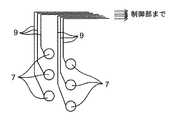
図1及び図2〜図5は、アシストウェア4のウェア本体2がパンツである例を示している。図1は、ユーザ1が、制御部8を内蔵したコントローラベルト3を腰に装着し、ウェア本体2を履いている状態を示している。このウェア本体2には、一例として、図2に示すように、パンツの縦方向、言い換えれば、ユーザ1の人体軸方向(図2の上下方向)に、例えば筋電センサで構成された多数のセンサ7と、多数のアシスト用アクチュエータ6とを所定間隔をあけてウェア本体2の図2の表裏両面に固定している(図5参照)。すなわち、多数のセンサ7が接続された配線9と、アシスト用アクチュエータ6とが交互に配置されている。一方、パンツの横方向、言い換えれば、人体軸方向(図2の上下方向)と直交する方向に、多数のウェアフィット用アクチュエータ5を、所定間隔をあけてウェア本体2の図2の表裏両面に固定している(図4参照)。 1 and 2 to 5 show an example in which the
具体的な例として、ウェアフィット用アクチュエータ5は、図4に示すように、ウェア本体2の軸方向の端部、例えば、腰部であるウェア本体2の上端部2aと、大腿部の付け根部2bと、ウェア本体の下端部2cとが、これらの端部2a〜2c以外の他の部分2eと比較して、密度が濃いように配置して、ウェア本体2が端部2a,2b,2cでユーザ1にしっかりと密着固定できるように構成している。すなわち、ウェア本体2の上端部2aと大腿部の付け根部2bとウェア本体2の下端部2cとにおいては、ウェアフィット用アクチュエータ5を駆動又は駆動停止することによりウェアフィット用アクチュエータ5を収縮又は伸長させて、ユーザ1に密着固定する締め付け状態と、密着固定が開放されて緩められた状態との間で変化させるように構成している。このような構成によれば、アシスト用アクチュエータ6の発生力をユーザ1に作用させる際に重要となる部分を、ウェアフィット用アクチュエータ5により、しっかりと締め付けられるので、アシスト用アクチュエータ6からのアシスト力を、より適切にユーザ1の筋肉などに作用させることができるようになる。また、ウェアフィット用アクチュエータ5は、端部2a〜2c以外の他の部分2eでも締め付けることにより、ウェア本体2の弛みを防止するようにしている。このようにすることで、端部2a〜2c以外の他の部分2eにおいてもセンサ7を、より適切にユーザ1に接触させられるようになる。 As a specific example, as shown in FIG. 4, the
また、具体的な例として、アシスト用アクチュエータ6は、図5に示すように、ウェア本体2の表裏の、大腿部の前側中央から腰部にかけての部分2d、及び、その部分2dに対応する大腿部の後側中央から腰部にかけての部分まで(筋肉に対応する領域)は、これらの部分2d以外の部分2fと比較して、密度が濃いように配置して、アシスト用アクチュエータ6からの補助力が大腿部の筋肉(図6の筋肉1b)に対して作用しやすいように構成している。このように、ウェアフィット用アクチュエータ5とアシスト用アクチュエータ6とは、それぞれの機能に応じて、言い換えれば、それぞれの機能が効率的に発揮できるように、異なる位置に粗密に配置するようにしている。 As a specific example, as shown in FIG. 5, the assisting
(アクチュエータ)
線状の各ウェアフィット用アクチュエータ5は、線状の各アシスト用アクチュエータ6と同じものを使用しているが、別に異なるアクチュエータを使用してもよい。(Actuator)
The linear wear-
この第1実施形態では、同じ構造のアクチュエータを線状のウェアフィット用アクチュエータ5及び線状のアシスト用アクチュエータ6に使用している。 In the first embodiment, actuators having the same structure are used for the linear wear-
図8は、アクチュエータ5,6の説明図である。図9はアクチュエータ5,6の拡大説明図である。図10は、別のアクチュエータの説明図である。図11〜図13は変形例にかかるアクチュエータの説明図である。各アクチュエータは、一例として、図8の(a)に示すように、例えば直径0.233mmのらせん状に巻かれた合成樹脂の線状部材で構成され、両端の電極5aに電圧が印加されて通電加熱されると、図8の(b)に示すように、全長が収縮する。一方、通電が解除されて自然放熱すると、元の長さまで伸長する。これは、図9に示すように、らせん状に捩じられている樹脂の線状部材が加熱により周方向に捩じりが発生することにより、全長が収縮することによる。自然放熱などにより冷却されると、周方向に捩じりが解除されることにより、全長が伸長することになる。各アクチュエータは、一本で使用してもよいし、図11及び図12に示すように、作用させる力の大きさに応じて、多数本のアクチュエータを並列して配置して同期して伸縮動作するようにしてもよい。また、図13に示すように、直交する2つの軸方向にそれぞれ多数本のアクチュエータを並列して配置して、直交する2つの軸方向にそれぞれ同期して伸縮動作するように配置してもよい。 FIG. 8 is an explanatory diagram of the
このようなアクチュエータの例としては、熱の印加により収縮する線状のアクチュエータ、具体的には、線状で軸方向に伸縮可能な高分子アクチュエータが例示できる。より具体的には、銀で表面がコーティングされたナイロン繊維を加撚してコイル化したアクチュエータで、銀コーティングに電流印加して通電加熱した時に、トルクが発生して収縮する一方、電流印加を解除すれば、元の長さまで伸長して復帰するものが使用できる。このようなアクチュエータは、駆動が容易で、重量当たりの出力を大きくできる。 As an example of such an actuator, a linear actuator that contracts by application of heat, specifically, a linear polymer actuator that can expand and contract in the axial direction can be exemplified. More specifically, an actuator in which a nylon fiber whose surface is coated with silver is twisted to form a coil. When an electric current is applied to the silver coating and energized and heated, torque is generated and contracted, while an electric current is applied. If it cancels | releases, the thing which expands and returns to the original length can be used. Such an actuator is easy to drive and can increase the output per weight.
アクチュエータの他の例としては、図10に示す、空気圧の調整により伸縮する線状の空圧アクチュエータが使用できる。この空圧アクチュエータの一例としては、ゴムチューブ30の両端にフランジ33を固定し、ゴムチューブ30の外周に網目状繊維31が巻き付けられて構成したマッキベン型アクチュエータ32でもよい。このマッキベン型アクチュエータ32では、配管34から流体(空気等)を一方のフランジ33を通してゴムチューブ30内に流入させると、ゴムチューブ30は加圧されて膨張するが、網目状繊維31により拘束されているため、ゴムチューブ30は半径方向(図10の(c)参照)には膨張するが、中心軸方向には大きく収縮するよう動作する(図10の(b)参照)。一方、配管34から流体(空気等)を一方のフランジ33を通してゴムチューブ30内から排出させると、ゴムチューブ30は減圧されてゴムチューブ30は半径方向(図10の(c)参照)には網目状繊維31と共に収縮するが、中心軸方向には大きく伸長するよう動作する。具体的な一例としては、マッキベン型アクチュエータ32は外径1.2mmのものが既に開発されている。このようなアクチュエータは、ゴムチューブ30内への流体の出入りを遮断することで、容易に保持動作が実現できる。 As another example of the actuator, a linear pneumatic actuator shown in FIG. 10 that expands and contracts by adjusting the air pressure can be used. As an example of this pneumatic actuator, a
ウェアフィット用アクチュエータ5の機能としては、ユーザ1の部位の軸方向に対して交差(例えば直交)する方向沿いに配置して、アシスト用アクチュエータ6をユーザ1側に接触させるような力を作用させる。ウェアフィット用アクチュエータ5としては、少なくとも、ウェア本体2の軸方向の両端部の領域に配置して、ウェア本体2を両端部でユーザ1にしっかりと固定している。さらに、一例として、ウェア本体2がパンツの場合には、脚の付け根の領域などにも、ウェアフィット用アクチュエータ5を配置して、ウェア本体2をユーザ1にしっかりと固定している。例えば、関節をまたいでウェア本体2をユーザ1に装着するとき、関節の両側の領域にも、ウェアフィット用アクチュエータ5を配置して、ウェア本体2をユーザ1にしっかりと固定している。ウェアフィット用アクチュエータ5を駆動することにより、ウェア本体2の緩みを無くして締め付け状態にする。ウェア本体2の緩みを無くして締め付け状態にすることは、ユーザ1に対してウェア本体2のサイズ調整を行っているとも解釈できる。すなわち、ウェアフィット用アクチュエータ5を駆動することにより、ウェア本体2をユーザ1に締め付け状態にすれば、ウェア本体2のサイズ又はユーザ1の体型による締め付け状態の差異を無くすことができる。また、ウェア本体2の装着前は、ウェアフィット用アクチュエータ5を駆動せずに、緩み状態で履きやすくする。ウェア本体2の装着後に、ウェアフィット用アクチュエータ5を駆動して締め付け状態に変更して、ウェア本体2をアシスト用アクチュエータ6と共にユーザ1にしっかりと固定している。この結果、アシスト用アクチュエータ6からのアシスト力が確実にかつより適切に筋肉1bに伝えることができる。一方、ウェア本体2の脱着時には、ウェアフィット用アクチュエータ5の駆動を停止して、ウェア本体2を再び緩み状態として、脱ぎやすくすることができる。 As a function of the
アシスト用アクチュエータ6は、ユーザ1の部位の軸方向(言い換えれば、当該部位の筋肉の軸方向)に配置する一例であるが、これに限られるものではなく、部位の軸方向に対して交差する方向(例えば、直交する方向又は斜め方向など任意の方向)に配置することもできる。一例として、図6の筋肉1bの動きに沿ってアシスト用アクチュエータ6を伸縮させると、筋肉1bの動きをアシストさせることができる。 The assisting
(センサ)
センサ7の例としては、生体の信号の例として筋肉を動かすときに生じる電圧である筋電を測定する筋電センサを例示している。筋電センサは、筋肉に対する脳からの指令を検出できることから、筋動作へのアシストの追従性が高められる。しかしながら、センサ7としては、これに限られるものではなく、歪センサ、加速度センサ、又は、ジャイロセンサなども使用することができる。また、センサ7として筋電センサを使用する場合には、詳しくは後述するが、フィット動作時のしわ39の検出を行うことができる利点もある。(Sensor)
As an example of the
センサ7の配置と筋肉1bとの関係を図14に示す。各センサ7の位置としては、筋肉1bの動きが測定できる位置とし、例えば、筋肉1bに対応する位置のうち、筋肉が最も大きく動く位置に対応する位置に配置すれば、センサ7により筋肉1bの動きを検出しやすくなる。具体的には、例えば図6及び図7に示すように、1個又は複数のセンサ7を、ウェア本体2の表裏両面の筋肉1bに対応する領域2gに配置して、筋肉1bの動きをセンサ7で測定しやすくしている。より具体的には、ウェア本体2の表面では、大腿直筋などの大腿筋に対応する位置又は領域2gにセンサ7を配置する。ウェア本体2の裏面では、臀部の筋肉とハムストリングに対応する位置又は領域2gにセンサ7を配置する。 The relationship between the arrangement of the
また、それぞれのセンサ7からの配線9は、アナログ配線の場合は図15に示すような配線となる。このような構成は、各センサ7の信号を独立して検出できる。一方、それぞれのセンサ7からの配線9が、デジタル配線の場合は図16に示すような共通配線としてデジタル通信バスを利用した配線となる。このような構成は、配線を少なくできる。 Further, the
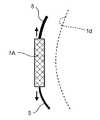
また、センサ7の別の例としては、フィット状態を検出するための軸方向力センサ7Aと、垂直方向力センサ7Bとがある。図17及び図18は、軸方向力センサ7Aをユーザ1に取り付けた状態の平面的な説明図及び側面的な説明図である。図19及び図20は、垂直方向力センサ7Bをユーザ1に取り付けた状態の平面的な説明図及び側面的な説明図である。 As another example of the
軸方向力センサ7Aは、図17及び図18に示すように、ユーザ1の脚1dに装着する場合、ウェアフィット用アクチュエータ5の中間部に軸方向力センサ7Aが固定され、ウェアフィット用アクチュエータ5の伸縮時の力を軸方向力センサ7Aで直接測定(検出)できるようにしている。 As shown in FIGS. 17 and 18, when the
垂直方向力センサ7Bは、図19及び図20に示すように、ユーザ1の脚1dに装着する場合、ウェアフィット用アクチュエータ5のユーザ側にユーザ1と接触するように配置し、垂直方向力センサ7Bにより、ウェアフィット用アクチュエータ5の伸縮動作によりユーザ側に作用する垂直力を測定(検出)できるようにしている。 As shown in FIGS. 19 and 20, the
軸方向力センサ7A、垂直方向力センサ7Bなどのセンサ7で検出された力は、制御部8に出力されて、ウェアフィット用アクチュエータ5の伸縮動作制御に使用される。 The force detected by the
例えば、制御部8によるセンサ出力に基づくウェアフィット用アクチュエータ5の力制御動作のフローチャートを、図21に示す。 For example, a flowchart of the force control operation of the
図21に示すように、まず、ステップS1で、制御部8で力しきい値を決定する。この力しきい値は、センサ7の信号検出に十分な押し付け圧、アシスト用アクチュエータ6の浮き、又は、端部のずれを抑えるのに十分な圧力、等を加味して設定される。 As shown in FIG. 21, first, in step S1, the
次いで、ステップS2で、センサ7により力を検出して制御部8に出力する。なお、センサ7により力が検出されない場合には、検出されるまで待機する。 Next, in step S <b> 2, the force is detected by the
次いで、ステップS3で、ステップS2で検出された力が、ステップS1で決定されたしきい値を越えているか否かを制御部8で判定する。もし、ステップS2で検出された力が、ステップS1で決定されたしきい値を越えていると制御部8で判定した場合には、ステップS4に進み、ウェアフィット用アクチュエータ5の駆動を制御部8で停止して、ステップS2に戻る。一方、もし、ステップS2で検出された力が、ステップS1で決定されたしきい値を越えていないと制御部8で判定した場合には、ステップS5に進み、ウェアフィット用アクチュエータ5を駆動し続ける。その後、ステップS2に戻る。 Next, in step S3, the
このように、センサ7での出力を基に、制御部8でウェアフィット用アクチュエータ5を駆動制御すれば、ウェアフィット用アクチュエータ5でのウェア本体2のユーザ1への装着力が過度にユーザ1に作用せず、安全に使用することができるとともに、適切な装着状態と装着解除状態とを確保することができる。 In this way, if the wear-fitting
センサ7の具体的な配置位置としては、図22に示すように、ウェア本体2の腰部2aと、大腿部の付け根部2bと、ウェア本体の下端部2cとなどの他、他の部分2eにおいてそれぞれ配置したウェアフィット用アクチュエータ5にセンサ7(センサ7A又は7B)を配置して、前記した効果を発揮するように構成することができる。 As shown in FIG. 22, the specific arrangement position of the
すべてのセンサ7とウェアフィット用アクチュエータ5とアシスト用アクチュエータ6とは、配線9をパンツの上端部である腰部に集約して、リング状のコントローラベルト3に配線を接続している。 All the
コントローラベルト3は、両端の係合部3aを有しており、ユーザ1の腰部に嵌めて、係合部3aで係合させて腰部に装着できるようにしている。係合部3aにはスイッチを設けて、係合部3aを係合させれば、ウェアフィット用アクチュエータ5の開始信号が制御部8に入力されるように構成してもよい。また、下記する入出力装置16からウェアフィット用アクチュエータ5の開始信号を制御部8にユーザ1が入力するようにしてもよい。 The
コントローラベルト3には、操作装置18を備えている。この操作装置18は、図3Aに示すように、スマートフォンなどの情報端末機15と通信可能でかつ操作ボタンとスピーカとLEDとディスプレイと無線通信機器となどを有する入出力装置16と、入出力装置16と接続された制御部8とを備えている。なお、入出力装置16は、スマートフォンなどの情報端末機15と通信するための無線通信機器を備えずに、入出力装置16での直接入力のみを受け付けるようにしてもよい。ユーザ1は、アシスト開始及び終了などの指示を、入出力装置16に直接入力するか、又は、情報端末機15を介して入出力装置16に間接的に入力して、ウェアフィット用アクチュエータ5とアシスト用アクチュエータ6とのそれぞれの駆動を制御部8で制御する。 The
入出力装置16には、フィット動作(ウェアフィット用アクチュエータ5の駆動)開始及び終了、アシスト動作(アシスト用アクチュエータ6の駆動)開始及び終了、しわに対する対策完了信号などの指示が入力されて、制御部8に伝達される。フィット動作(ウェアフィット用アクチュエータ5の駆動)開始及び終了信号の入力は、例えば、コントローラベルト3の係合部3aの係合動作及び係合解除動作で自動的に入力するようにしてもよい。また、制御部8からの警告指示に応じて、警告動作(スピーカからの警告音発生、ディスプレイでの警告表示、振動装置での警告用振動発生など)を入出力装置16で実施する。 Instructions such as start and end of a fit operation (drive of the wear fit actuator 5), start and end of an assist operation (drive of the assist actuator 6), a wrinkle countermeasure completion signal, and the like are input to the input /
スマートフォンなどの情報端末機15としては、人体1であるユーザが、フィット動作(ウェアフィット用アクチュエータ5の駆動)開始及び終了、アシスト動作(アシスト用アクチュエータ6の駆動)開始及び終了、しわに対する対策完了信号などの指示を入力可能とする。情報端末機15に入力された指示は、情報端末機15から制御部8に伝達される。制御部8からの警告指示に応じて、前記した警告動作を情報端末機15で実施してもよい。 As the
制御部8は、記憶部8aと、演算部8bと、判定部8cと、アクチュエータ選択部8eと、駆動部8dとを備えている。制御部8は、操作装置18からの指示に従って、センサ7の信号を基に、ウェアフィット用アクチュエータ5とアシスト用アクチュエータ6とのそれぞれの駆動を制御する。 The
記憶部8aには、ウェアの締め付け時の判定に用いるしきい値(第1しきい値、第2しきい値、誤差検出用しきい値等)を記憶しているとともに、アシストの力の強さ又はアシストのタイミングなどが異なる複数もしくは単一のアシスト動作モード等を記憶しておく。アシスト動作モードには、例えば、歩行モード、又は、階段の昇降モードなどが含まれる。記憶部8aには、各アシスト動作モード毎に、演算部8bで演算したセンサ7の値の時間変化に対応した変化パターンを記憶している。さらに、記憶部8aには、判定部8cでアシスト用アクチュエータ6の動作を決定するのに用いるプログラム等も記憶している。また、記憶部8aには、各センサ7の位置情報、各センサ7に対応するウェアフィット用アクチュエータ5の位置情報、及び、各センサ7に対応するアシスト用アクチュエータ6の位置情報も予め記憶されている。 The
演算部8bは、センサ7からの複数の出力信号のうちから、最も強い信号又は比較的強い信号を抽出したり、センサ7からの複数の出力信号に重み付けした上で平均化したりするセンサキャリブレーションの演算を必要に応じて実施する。また、演算部8bは、センサ7の出力信号に対してゲイン調整又はノイズキャンセル等の演算を行うようにしてもよい。演算部8bでの演算結果は、演算部8bから判定部8cに伝達される。 The
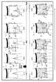
ウェアの締め付け時には、判定部8cは、演算部8bで演算したセンサ7の値と記憶部8aから読み出されるしきい値との大小を比較判定する。判定部8cは、センサ7が軸方向力センサ7A又は垂直方向力センサ7Bである場合、締め付け力が第1しきい値又は第2しきい値を越えているか否かで、ウェアフィット用アクチュエータ5の動作を決定し、必要に応じてアクチュエータ選択部8eに指示を伝達する。また、判定部8cは、センサ7が筋電センサの場合、検出電位が誤差検出用しきい値を越えているか否かでしわ検出を実施し、その結果に基づいて、ウェアフィット用アクチュエータ5の動作を決定し、必要に応じて、アクチュエータ選択部8eに指示を伝達したり、必要に応じて操作装置18に警告指示を伝達したりする。一方、アシストフェーズの場合には、判定部8cは、演算部8bで演算したセンサ7の値の時間変化と記憶部8aから読み出されるアシスト動作モードに応じた変化パターンとを比較してユーザの動作又は状態を判定する。また、判定部8cは、記憶部8aに予め記憶されたプログラムなどに基づき、アシスト用アクチュエータ6の動作を決定し、必要に応じてアクチュエータ選択部8eに指示を伝達する。一例として、図3Bには、図34のウェアアシスト4による歩行アシストの工程(フェーズA〜G)のうちのフェーズEでの歩行状態の判定のための実際の信号と、記憶部8aに記憶された各フェーズの信号(代表例として、フェーズE,F,Gのみ図示。)とを示す。図3C及び図3Dには、2つのセンサ7のフェーズEの時間応答パターンの例と、フェーズEでのアシスト用アクチュエータ6(代表例として、アクチュエータA〜Eのみ図示。)の駆動例を示す。図34では、ユーザの動作又は状態を判定するとき、実際の信号と、記憶部8aに記憶された各フェーズの信号とを判定部8cで比較する。すると、実際の信号と、図3Cに示すような時間応答パターンのフェーズEの信号とが最も一致するので、ユーザの歩行状態はフェーズEであると、判定部8cで判定することができる。この判定部8cでの判定結果と記憶部8aに予め記憶されたプログラム(ここでは、歩行用プログラム)とに基づき、判定部8cは、図3Dに示すように、フェーズEでのアシスト用アクチュエータ6(代表例として、アクチュエータA〜Eのみ図示。)の駆動例に基づき、アシスト用アクチュエータ6の動作を決定し、アクチュエータ選択部8eを介して駆動部8dに指示を伝達する。駆動部8dは、判定部8cからの指示に基づき、対応するアシスト用アクチュエータ6(代表例として、アクチュエータA〜E)を駆動する。 When tightening the wear, the
(ウェア本体)
ウェア本体2の第1構造例45としては、図23に示すように、まず、ユーザ1に最も近い側の第1層41には、センサ7及びその配線9を配置している。第1層41上の第2層42には、ウェアフィット用アクチュエータ5を配置している。第2層42の上の第3層43には、ウェアフィット用アクチュエータ5の軸方向と交差するような軸方向を有するアシスト用アクチュエータ6を配置している。最外層の第4層44には、第3層43を全て覆う、布などのカバーを配置している。この結果、第1構造例45は、全体として4層構造としている。なお、図23の46はアシスト用アクチュエータ6の両端を固定するアシスト用アクチュエータ固定部、47はアシスト用アクチュエータ6の配線である。(Wear body)
As a first structural example 45 of the wear
この第1構造例45によれば、簡単な構造であり、また、全てのアシスト用アクチュエータ6はウェアフィット用アクチュエータ5よりも外側に配置されており、ウェアフィット用アクチュエータ5により押圧されることが無いため、アシスト用アクチュエータ6の伸縮動作時の摩擦を少なくすることができる。 According to the first structural example 45, the structure is simple, and all the assisting
ウェア本体2の第2構造例55としては、図24に示すように、まず、ユーザ1に最も近い側の第1層51には、センサ7及びその配線9を配置している。第1層51の上の第2層52には、アシスト用アクチュエータ6を配置するとともに、アシスト用アクチュエータ6の軸方向と交差するような軸方向を有するウェアフィット用アクチュエータ5を配置している。第2層52において、アシスト用アクチュエータ6の両端部近くではウェアフィット用アクチュエータ5を後述する第3層側に配置するとともに、それ以外の部分では、ウェアフィット用アクチュエータ5を第1層側に配置している。第2層52の上の最外層の第3層53には、第2層52を全て覆う、布などのカバーを配置している。この結果、第2構造例55は、全体として3層構造としている。なお、図24の56はアシスト用アクチュエータ6の両端を固定するアシスト用アクチュエータ固定部、57はアシスト用アクチュエータ6の配線である。 As a second structural example 55 of the wear
この第2構造例55によれば、アシスト用アクチュエータ6の両端をウェアフィット用アクチュエータ5によりユーザ1に向けてしっかり押さえることでアシスト用アクチュエータ6から筋肉1bへの補助力の伝達効率を向上させる一方、それ以外の部分では、ウェアフィット用アクチュエータ5がアシスト用アクチュエータ6よりもユーザ1に近い位置に配置されているため、ウェアフィット用アクチュエータ5により押圧されることが無いため、アシスト用アクチュエータ6の伸縮動作時の摩擦を少なくすることができる。 According to the second structural example 55, the assisting
ウェア本体2の第3構造例65としては、図25に示すように、まず、ユーザ1に最も近い側の第1層61には、センサ7及びその配線9を配置している。中間の第2層62には、アシスト用アクチュエータ6を配置している。第2層62上の第3層63には、ウェアフィット用アクチュエータ5を配置している。第3層63の上の最外層である第4層64には、第3層63を全て覆う、布などのカバーを配置している。この結果、第3構造例65は、全体として4層構造としている。なお、図25の66はアシスト用アクチュエータ6の両端を固定するアシスト用アクチュエータ固定部、67はアシスト用アクチュエータ6の配線である。 As a third structural example 65 of the wear
この第3構造例65によれば、簡単な構造であり、かつ、ウェアフィット用アクチュエータ5がアシスト用アクチュエータ6の外側に配置されているため、ウェアフィット用アクチュエータ5によりアシスト用アクチュエータ6をユーザ1に向けてしっかり押さえることができる。 According to the third structural example 65, since the wear-
ウェア本体2の第4構造例75としては、図26に示すように、まず、ユーザ1に最も近い側の第1層71には、センサ7及びその配線9を配置している。第1層71の上の第2層72には、アシスト用アクチュエータ6をジクザク状に配置するとともに、アシスト用アクチュエータ6の軸方向と交差するような軸方向を有するウェアフィット用アクチュエータ5を、アシスト用アクチュエータ6に対して第1層側と後述する第3層側とに交互に配置している。第2層72の上の最外層の第3層73には、第2層72を全て覆う、布などのカバーを配置している。この結果、第4構造例75は、全体として3層構造としている。なお、図26の76はアシスト用アクチュエータ6の両端を固定するアシスト用アクチュエータ固定部、77はアシスト用アクチュエータ6の配線である。 As a fourth structure example 75 of the wear
この第4構造例75によれば、ウェアフィット用アクチュエータ5とアシスト用アクチュエータ6とが交互に配置されているので、ウェアフィット用アクチュエータ5とアシスト用アクチュエータ6とがしっかり固定され、位置ずれが起こりにくい。なお、第4構造例75では、アシスト用アクチュエータ6に対してウェアフィット用アクチュエータ5が上に来る場合と下に来る場合とが交互に入れ替わっているが、これに限るものではなく、任意の回数ごとに入れ替わってもよい。 According to the fourth structural example 75, since the wear-
(センサキャリブレーション)
図27は、センサキャリブレーションの説明図である。図28は、センサ出力の処理の仕方の説明図である。図29は、別のセンサ出力の処理の仕方の説明図である。(Sensor calibration)
FIG. 27 is an explanatory diagram of sensor calibration. FIG. 28 is an explanatory diagram of a sensor output processing method. FIG. 29 is an explanatory diagram of another sensor output processing method.
ユーザの特性(体型、男女、年齢など)、又は、ウェア本体2のユーザ1に対するフィット具合などにより、実際には、センサ7の位置がユーザ毎又は装着する度に異なってしまう。このような場合、ユーザ1が自ら逐一調整しないで済むように、制御部8でセンサキャリブレーションを自動的に行うことも可能である。 Actually, the position of the
例えば、図27に示すように、まず、目標筋肉1eに対応して配置されるセンサ目標領域2h近傍のセンサ7で、筋電などの生体信号を取得する。なお、この図27では、ウェア本体2の全体に対してセンサ7が均等に配置されている。 For example, as shown in FIG. 27, first, a biosignal such as myoelectricity is acquired by the
次いで、センサ7で取得した生体信号のうちから、最も強い信号を制御部8の演算部8bで抽出する。一例として、図28に示すように、4個のセンサ7、すなわち、センサ7−1、7−2、7−3、7−4からの出力信号を(1)、(2)、(3)、(4)とすると、センサ7−4からの出力信号(4)が最も強い信号である。 Next, the strongest signal is extracted by the
この結果、この最も強い信号である出力信号(4)を検出したセンサ7を、センサ目標領域2hでのセンサ7として、制御部8で取り扱う。このようにすれば、センサ目標領域2h内でのセンサ7のみでは、力を十分に検出できずに誤作動を発生させる可能性があったとしても、センサ目標領域2h近傍の複数のセンサ7からの出力信号を考慮して、最も強い信号を抽出して対応するセンサ7を、使用すべき適切なセンサ7として制御部8で選択することにより、補正、すなわち、センサキャリブレーションを行うことができる。 As a result, the
このセンサキャリブレーションの別の処理の仕方としては、最も強い信号のみを抽出するのではなく、図29に示すように、制御部8の演算部8bにおいて、出力信号(1)、(2)、(3)、(4)にそれぞれに重み付け係数を乗算し、それらを全て加算したのち、出力信号の個数で除算することにより、出力信号の平均値を算出する。このようにして算出した出力信号の平均値を、補正された出力信号として取得し、これを使用することにより、センサキャリブレーションを行うこともできる。 As another processing method of this sensor calibration, instead of extracting only the strongest signal, as shown in FIG. 29, the
一例として、このキャリブレーションは、次のようなタイミングで行う。図30は、ウェアアシストでの全体の動作の流れを示すフローチャートである。 As an example, this calibration is performed at the following timing. FIG. 30 is a flowchart showing the overall operation flow in wear assist.
すなわち、図30に示すように、まず、ステップS11で、ウェア本体2をユーザ1に装着したのち、ウェアフィット用アクチュエータ5を駆動してウェア本体2をユーザ1にフィットさせる。 That is, as shown in FIG. 30, first, in step S <b> 11, the wear
その後、ステップS12で、前記したようにセンサキャリブレーションを行う。 Thereafter, in step S12, sensor calibration is performed as described above.
最後に、ステップS13で、アシスト用アクチュエータ6でのアシスト動作を行う。このとき、例えば、アシスト動作モードが複数選択可能である場合には、入出力装置16により、いずれかのモードを選択するようにしてもよい。例えば、歩行モード及び階段の昇降モードがある場合には、いずれかを選択したのち、アシストを開始する。 Finally, in step S13, an assist operation is performed by the
(アクチュエータキャリブレーション)
図31及び図32は、ユーザ1により筋肉の位置が異なるために異なるアシスト用アクチュエータを選択する場合の説明図である。図33は、アクチュエータキャリブレーションの動作の流れを示すフローチャートである。(Actuator calibration)
FIG. 31 and FIG. 32 are explanatory diagrams in the case where different assisting actuators are selected because the positions of muscles differ depending on the
前記した複数のセンサ7からの出力信号のうち最も強い信号のセンサ7を抽出したのち、そのセンサ7に対応して配置された(例えば、そのセンサ7の近くに配置された)アシスト用アクチュエータ6を制御部8でさらに選択すれば、アシスト用アクチュエータ6から筋肉1dに対して、アシスト用アクチュエータ6からの補助力を適切に伝達することができる。例えば、図31に示すように、あるユーザ1では、ウェア本体2の縦方向に配置されたアシスト用アクチュエータ6のうち、大腿部及びその付近に対応するアシスト用アクチュエータ6A〜6Fのうち、他のアシスト用アクチュエータ6A,6B,6E,6Fよりも信号が強い2本のアシスト用アクチュエータ6Cと6Dとを使用すればよい。これに対して、図32に示すように、ある別のユーザの1では、筋肉の位置が先のユーザとは異なるため、ウェア本体2の縦方向に配置されたアシスト用アクチュエータ6のうち、大腿部及びその付近に対応するアシスト用アクチュエータ6A〜6Fのうち、他のアシスト用アクチュエータ6A,6D,6E,6Fよりも信号が強い2本のアシスト用アクチュエータ6Bと6Cとを使用すればよい。このように、センサ7の出力データに基づき、制御部8でウェア本体2に対する筋肉1bの位置を検出し、筋肉1bに最も近いアシスト用アクチュエータ6を制御部8で適切に選択することができる。なお、各センサ7の位置情報、及び、各センサ7に対応するアシスト用アクチュエータ6の位置情報は、制御部8の記憶部8aに予め記憶しておく。 After extracting the
一例として、このアクチュエータキャリブレーションは、次のようなタイミングで行う。 As an example, this actuator calibration is performed at the following timing.
すなわち、図33に示すように、まず、ステップS15で、ウェア本体2をユーザ1に装着したのち、ウェアフィット用アクチュエータ5を駆動してウェア本体2をユーザ1にフィットさせたのち、センサ目標領域2h近傍の複数のセンサ7から検出データを制御部8で取得する。 That is, as shown in FIG. 33, first, in step S15, after the wear
その後、ステップS16で、一例として、複数のセンサ7の検出データのうち最も強い信号のセンサ7を、使用するセンサ7として制御部8で決定する。 Thereafter, in step S16, as an example, the
最後に、ステップS17で、決定したセンサに対応するアシスト用アクチュエータ6を、使用するアシスト用アクチュエータ6として制御部8で決定する。 Finally, in step S17, the assisting
(歩行アシスト)
図34は、ウェアアシスト4による歩行アシストの工程の説明図である。(Walking assist)
FIG. 34 is an explanatory diagram of a walk assist process by the
図34に示すように、制御部8の制御の下での、右の大腿部の前後の筋肉1bに対するアシスト用アクチュエータ6によるアシストは、一例として以下のようにして行われる。このアシストは、センサ7により検出される筋肉1bの動きに連動したアシスト力を発生することで行われている。ここでは、説明を簡単にするため、右の大腿部の前後の筋肉1bに対するアシスト用アクチュエータ6についてのみ説明するが、左の大腿部の前後の筋肉1bに対するアシスト用アクチュエータ6についても同様である。 As shown in FIG. 34, the assist by the assisting
まず、G状態〜A状態に向かうとき、ユーザ1が、右足を前に出して、一歩、歩き始める。このとき、右の大腿部の前側の筋肉1bに対応するアシスト用アクチュエータ6によるアシストを増加させるが、右の大腿部の後側の筋肉1bに対応するアシスト用アクチュエータ6によるアシストは徐々に減少させている。 First, when going to the G state to the A state, the
次いで、A状態〜B状態に向かうとき、ユーザ1が、右足に体重を乗せて支えつつ、左足を地面から離し始める。このB状態に移行するとき、右の大腿部の前側の筋肉1bに対応するアシスト用アクチュエータ6によるアシストを、ピークアシストの値に到達するまで、最大限行う。このとき、右の大腿部の後側の筋肉1bに対応するアシスト用アクチュエータ6によるアシストはわずかしか行わない。 Next, when going to the A state to the B state, the
次いで、B状態〜C状態に向かうとき、ユーザ1が、右足に全体重を乗せて支える一方、左足を地面から完全に離している。このとき、右の大腿部の前側の筋肉1bに対応するアシスト用アクチュエータ6によるアシストは徐々に減少させ、右の大腿部の後側の筋肉1bに対応するアシスト用アクチュエータ6によるアシストはわずかしか行わない。 Next, when heading from the B state to the C state, the
次いで、C状態〜D状態に向かうとき、ユーザ1が、左足を前に出して、さらに一歩、歩き始める。このとき、右の大腿部の前側と後側との両方の筋肉1bに対応するアシスト用アクチュエータ6によるアシストはわずかしか行わない。 Next, when going to the C state to the D state, the
次いで、D状態〜E状態に向かうとき、ユーザ1が、左足に体重を乗せて支えつつ、右足を地面から離し始める。このD状態からE状態に移行するとき、右の大腿部の前側の筋肉1bに対応するアシスト用アクチュエータ6によるアシストを増加させる。このとき、右の大腿部の後側の筋肉1bに対応するアシスト用アクチュエータ6によるアシストはわずかしか行わない。 Next, when moving from the D state to the E state, the
次いで、E状態〜F状態に向かうとき、ユーザ1が、左足に全体重を乗せて支える一方、右足を地面から完全に離している。このとき、右の大腿部の前側の筋肉1bに対応するアシスト用アクチュエータ6によるアシストは徐々に減少させ、右の大腿部の後側の筋肉1bに対応するアシスト用アクチュエータ6によるアシストはわずかしか行わない。 Next, when going to the E state to the F state, the
次いで、F状態〜G状態に向かうとき、ユーザ1が、右足を前に出して、さらに一歩、歩き始める。このF状態からG状態に移行するとき、右の大腿部の後側の筋肉1bに対応するアシスト用アクチュエータ6によるアシストを、ピークアシストの値に到達するまで、最大限増加させる。このとき、右の大腿部の前側の筋肉1bに対応するアシスト用アクチュエータ6によるアシストはわずかしか行わない。 Next, when going to the F state to the G state, the
以上、本アシスト例では、筋肉1bの動きに連動してアシスト力徐々に変化させているが、これに限るものではなく、アシストが必要なタイミングでパルス的にアシスト力を発生させるなどしても良い。また、アシストをわずかしか行わない場合などでは、アシストを一切行わないようにしても良い。 As described above, in the present assist example, the assist force is gradually changed in conjunction with the movement of the
(アシストフェーズ)
図35は、制御部8によるアシスト用アクチュエータ6の駆動制御のフローチャートである。(Assist phase)
FIG. 35 is a flowchart of drive control of the assisting
図35に示すように、制御部8によるアシスト用アクチュエータ6の駆動制御は、以下のようにして行われる。ここでは、ユーザ1の歩行状態に応じて、アシストするアシスト用アクチュエータ6が異なっている。センサ7からは、対応するそれぞれの筋肉1bの動きが情報として得られるので、それらの情報を例えば人の歩行パターンと制御部8で照らし合わせることで、ユーザ1の歩行状態を識別することができる。それにより、制御部8において、駆動される筋肉1bに対応したアシスト用アクチュエータ6を選択し、筋肉1bに同期してアシストすることが可能になる。 As shown in FIG. 35, the drive control of the assisting
まず、ステップS21で、ユーザ1から入出力装置16を使用して、歩行モード等の指示が入力される。 First, in step S21, an instruction such as a walking mode is input from the
次いで、ステップS22で、アシストを制御部8で開始する。すなわち、アシスト用アクチュエータ6を制御部8の記憶部8aに予め記憶されたプログラムなどに基づき、アシスト用アクチュエータ6の駆動制御を開始する。 Next, in step S <b> 22, the assist is started by the
次いで、ステップS23で、まず、アシスト用アクチュエータ6の駆動制御を実際に開始する前に、全てのセンサ7からのデータを制御部8で取得する。 Next, in step S23, first, data from all the
次いで、ステップS24で、制御部8で取得した全てのセンサ7からのデータを基に、制御部8で、ユーザ1の動作又は状態を制御部8で決定する。例えば、現在、歩行中であるか否か、歩行中であれば、どのような状態であるかなどを制御部8で決定する。 Next, in step S <b> 24, based on the data from all the
次いで、ステップS25で、決定されたユーザ1の動作又は状態に基づき、各アシスト用アクチュエータ6の目標動作を制御部8で決定する。 Next, in step S25, based on the determined motion or state of the
次いで、ステップS26で、ステップS25での決定された目標動作に基づいて、アシスト用アクチュエータの駆動制御を制御部8で行う。 Next, in step S26, the
次いで、ステップS27で、入出力装置16などにより指示変更があるか否かを制御部8で判定する。もし指示変更があると制御部8で判定すれば、ステップS28に進む。もし指示変更がないと制御部8で判定すれば、ステップS23に戻る。 Next, in step S27, the
次いで、ステップS28で、指示変更は終了指示であるか否かを制御部8で判定する。もし指示変更が終了指示でないと制御部8で判定すれば、ステップS30に進む。もし指示変更が終了指示であると制御部8で判定すれば、ステップS29に進む。 Next, in step S28, the
次いで、ステップS29で、一連の動作処理を終了する。 Next, in step S29, a series of operation processing is terminated.
ステップS30では、指示変更に基づく設定変更を制御部8で行ったのち、ステップS23に戻る。 In step S30, the
(ウェア本体の締め付け)
図36は、ウェア本体2をユーザ1に締め付けるときの一連の動作の説明図である。図37は、別の方法での、ウェア本体2をユーザ1に締め付けるときの一連の動作の説明図である。(Tightening the wear body)
FIG. 36 is an explanatory diagram of a series of operations when fastening the wear
図36及び図37に基づき、ウェア本体2をユーザ1に締め付けるときの一連の動作について説明する。 A series of operations when the wear
図36は、ウェア本体2をユーザ1が履いたのち、ウェア本体2の下端部から上端部に向けて締め付けていく方法を説明している。図37は、逆に、ウェア本体2をユーザ1が履いたのち、ウェア本体2の上端部から下端部に向けて締め付けていく方法を説明している。いずれも、ウェア本体2の軸方向(縦方向)いずれか一方の端部から他方に端部に向けて締め付けていくようにしている。 FIG. 36 illustrates a method of tightening the wear
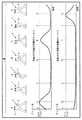
まず、図36は、ウェア本体2の一例としてのパンツをユーザ1が履いたのち、ウェア本体2の下端部から上端部に向けて締め付けていく方法について説明する。図36の上段の(1)〜(5)の状態はウェア本体2の外観を示し、下段の(11)〜(15)の状態はウェア本体2のウェアフィット用アクチュエータ5の状態を示している。(1)〜(5)の状態及び(11)〜(15)の状態は、それぞれ時系列順に並べられており、(1)〜(5)の状態は(11)〜(15)の状態にそれぞれ対応している。(11)〜(15)の状態では、ウェアフィット用アクチュエータ5が駆動されておらず収縮していない状態は点線で示し、ウェアフィット用アクチュエータ5が駆動されて収縮した状態は実線で示している。なお、ウェアフィット用アクチュエータ5を制御部8で駆動させるとき、ウェアフィット用アクチュエータ5が徐々に収縮するように駆動制御している。また、ウェア本体2の外形が波線で表される部分は、緩んでいる状態の部分を示し、外形が直線で表される部分は、締め付けられた状態の部分を示し、上向きの矢印は、緩んでいる状態から締め付けられた状態に変化していく方向を示している。 First, FIG. 36 illustrates a method in which the
図36の(1)及び(11)の状態では、ユーザ1がウェア本体2を履いた直後の状態であり、ウェア本体2は全体的に緩く装着されている。この段階では、全てのウェアフィット用アクチュエータ5は駆動されていない。 36 (1) and (11) are the states immediately after the
次いで、図36の(2)及び(12)の状態では、ウェア本体2の下端部2cに配置された複数のウェアフィット用アクチュエータ5を制御部8で順に又は一斉に駆動して収縮させ、ウェア本体2の下端部2cを締め付けている。他の部分は、ウェアフィット用アクチュエータ5が駆動されていないため、緩んだ状態である。以下、同様に、各状態(3)〜(5)及び(13)〜(15)では、締め付け状態の部分のみを説明し、説明されていない部分は緩んだ状態である。 Next, in the states of (2) and (12) in FIG. 36, the plurality of wear
次いで、図36の(3)及び(13)の状態では、ウェア本体2の下端部2cに配置された複数のウェアフィット用アクチュエータ5を駆動して収縮した状態で、下端部2cのさらに上方に配置された複数のウェアフィット用アクチュエータ5を制御部8で順に又は一斉に駆動して収縮させ、ウェア本体2の下端部2cのさらに上方の部分までを締め付け状態としている。次いで、大腿部の付け根部2bに配置された複数のウェアフィット用アクチュエータ5を制御部8で順に又は一斉に駆動して収縮させ、ウェア本体2の下端部2c〜大腿部の付け根部2bまでを締め付け状態としている。 Next, in the states of (3) and (13) in FIG. 36, the plurality of wear
次いで、図36の(4)及び(14)の状態では、ウェア本体2の下端部2c〜大腿部の付け根部2bまでに配置された複数のウェアフィット用アクチュエータ5を駆動して収縮した状態で、大腿部の付け根部2bの上方に配置された複数のウェアフィット用アクチュエータ5を制御部8で順に又は一斉に駆動して収縮させ、ウェア本体2の下端部2c〜大腿部の付け根部2bの上方の部分までを締め付け状態としている。 Next, in the states of (4) and (14) in FIG. 36, a plurality of wear
次いで、図36の(5)及び(15)の状態では、ウェア本体2の下端部2c〜大腿部の付け根部2bの上方の部分までに配置された複数のウェアフィット用アクチュエータ5を駆動して収縮した状態で、ウェア本体2の上端部2aに配置された複数のウェアフィット用アクチュエータ5を制御部8で順に又は一斉に駆動して収縮させ、ウェア本体2の下端部2c〜ウェア本体2の上端部2a、すなわち、ウェア本体2全体を締め付け状態としている。 Next, in the states of (5) and (15) in FIG. 36, the plurality of wear
この結果、ウェア本体2を、下端部2cから上端部2aに向けて徐々にしわを伸ばしつつ緩められた状態から締め付け状態に変化させることができ、ウェア本体2をユーザ1にフィットさせることができる。 As a result, the wear
次に、図37は、ウェア本体2の一例としてのパンツをユーザ1が履いたのち、ウェア本体2の上端部から下端部に向けて逆に締め付けていく方法について説明する。図37の上段の(21)〜(26)の状態はウェア本体2の外観を示し、下段の(31)〜(36)の状態はウェア本体2のウェアフィット用アクチュエータ5の状態を示している。(21)〜(26)の状態及び(31)〜(36)の状態は、それぞれ時系列順に並べられており、(21)〜(26)の状態は(31)〜(36)の状態にそれぞれ対応している。(31)〜(36)の状態では、ウェアフィット用アクチュエータ5が駆動されておらず収縮していない状態は点線で示し、ウェアフィット用アクチュエータ5が駆動されて収縮した状態は実線で示している。なお、ウェアフィット用アクチュエータ5を制御部8で駆動させるとき、ウェアフィット用アクチュエータ5が徐々に収縮するように駆動制御している。また、ウェア本体2の外形が波線で表される部分は、緩んでいる状態の部分を示し、外形が直線で表される部分は、締め付けられた状態の部分を示し、上向きの矢印は、緩んでいる状態から締め付けられた状態に変化していく方向を示している。 Next, FIG. 37 illustrates a method in which the
図37の(21)及び(31)の状態では、ユーザ1がウェア本体2を履いた直後の状態であり、ウェア本体2は全体的に緩く装着されている。この段階では、全てのウェアフィット用アクチュエータ5は駆動されていない。 In the states of (21) and (31) in FIG. 37, the
次いで、図37の(22)及び(32)の状態では、ウェア本体2の上端部2aに配置された複数のウェアフィット用アクチュエータ5を制御部8で順に又は一斉に駆動して収縮させ、ウェア本体2の上端部2aを締め付けている。他の部分は、ウェアフィット用アクチュエータ5が駆動されていないため、緩んだ状態である。以下、同様に、各状態(23)〜(26)及び(33)〜(36)では、締め付け状態の部分のみを説明し、説明されていない部分は緩んだ状態である。 Next, in the states of (22) and (32) in FIG. 37, the plurality of wear
次いで、図37の(23)及び(33)の状態では、ウェア本体2の上端部2aに配置された複数のウェアフィット用アクチュエータ5を駆動して収縮した状態で、上端部2aのさらに下方に配置された複数のウェアフィット用アクチュエータ5を制御部8で順に又は一斉に駆動して収縮させ、ウェア本体2の上端部2aのさらに下方の部分までを締め付け状態としている。 Next, in the states of (23) and (33) in FIG. 37, the plurality of wear
次いで、図37の(24)及び(34)の状態では、大腿部の付け根部2bの上方に配置されたウェアフィット用アクチュエータ5を制御部8で駆動して収縮させ、ウェア本体2の上端部2a〜大腿部の付け根部2bの上方までを締め付け状態としている。 Next, in the states of (24) and (34) in FIG. 37, the
次いで、図37の(25)及び(35)の状態では、ウェア本体2の上端部2a〜大腿部の付け根部2bの上方までに配置された複数のウェアフィット用アクチュエータ5を駆動して収縮した状態で、大腿部の付け根部2bに配置された複数のウェアフィット用アクチュエータ5を制御部8で順に又は一斉に駆動して収縮させ、ウェア本体2の上端部2a〜大腿部の付け根部2bまでを締め付け状態としている。 Next, in the states of (25) and (35) in FIG. 37, a plurality of wear
次いで、図37の(26)及び(36)の状態では、ウェア本体2の上端部2a〜大腿部の付け根部2bまでに配置された複数のウェアフィット用アクチュエータ5を駆動して収縮した状態で、ウェア本体2の下端部2cに配置された複数のウェアフィット用アクチュエータ5を制御部8で順に又は一斉に駆動して収縮させ、ウェア本体2の上端部2a〜ウェア本体2の下端部2c、すなわち、ウェア本体2全体を締め付け状態としている。 Next, in the states of (26) and (36) in FIG. 37, a plurality of wear
この結果、ウェア本体2を、上端部2aから下端部2cに向けて徐々にしわを伸ばしつつ緩められた状態から締め付け状態に変化させることができ、ウェア本体2をユーザ1にフィットさせることができる。 As a result, the wear
(ウェア本体の装着時のウェアフィット用アクチュエータの動作手順)
図38は、ウェア本体2の装着時のウェアフィット用アクチュエータ5の動作手順のフローチャートである。(Operation procedure of wear fitting actuator when wearing the wear body)
FIG. 38 is a flowchart of the operation procedure of the
次に、ウェア本体2の装着時のウェアフィット用アクチュエータ5の動作手順について、図38を基に説明する。 Next, the operation procedure of the
まず、ステップS41で、コントローラベルト3の係合部3aを閉じて係合させることにより、ウェアフィット用アクチュエータ5の開始信号が制御部8に入力されるまで待機する。開始信号が制御部8に入力されると、ステップS42に進む。 First, in step S41, the
次いで、ステップS42で、ウェアフィット用アクチュエータ5としてi=1番目のウェアフィット用アクチュエータ5を制御部8で選択する。 Next, in step S <b> 42, the
次いで、ステップS43で、制御部8の制御の下に、制御部8で選択されたi=1番目のウェアフィット用アクチュエータ5の駆動を開始して、i=1番目のウェアフィット用アクチュエータ5を少し収縮させて締め付けを開始する。 Next, in step S43, under the control of the
次いで、ステップS44で、i=1番目のウェアフィット用アクチュエータ5の収縮が完了したか否かを軸方向力センサ7A、垂直方向力センサ7Bなどのセンサ7の情報を基に制御部8で判定する。i=1番目のウェアフィット用アクチュエータ5の収縮が完了していないと制御部8で判定すれば、ステップS43に戻る。i=1番目のウェアフィット用アクチュエータ5の収縮が完了したと制御部8で判定すれば、ステップS45に進む。 Next, in step S44, the
次いで、ステップS45で、全てのウェアフィット用アクチュエータ5の駆動すなわち収縮が完了したか否かを制御部8で判定する。全てのウェアフィット用アクチュエータ5の収縮が完了していないと制御部8で判定すれば、ステップS47に進む。全てのウェアフィット用アクチュエータ5の収縮が完了したと制御部8で判定すれば、ステップS46に進んで終了する。 Next, in step S45, the
ステップS47では、ウェアフィット用アクチュエータ5としてi=i+1番目のウェアフィット用アクチュエータ5を制御部8で選択したのち、ステップS43に進む。 In step S47, i = i + 1th wear
このように処理することにより、ウェア本体2の上端部2aから下端部2cに向けて、又は、下端部2cから上端部2aに向けて順に配置されたウェアフィット用アクチュエータ5を1本ずつ順に駆動制御することができる。このような構成の場合、ウェアフィット用アクチュエータ5を駆動してウェア本体2をユーザ1に締め付けてフィットさせる際、1本ずつフィットさせているため、ユーザが適切にフィットできていない位置をユーザ自身が把握し易い。その結果、エラー位置をユーザに提示せずとも、ユーザ自身によるエラー位置の修正(ウェア本体2のしわ伸ばしなど)を促すことができる。 By processing in this way, the
(ウェア本体の脱衣動作)
図39は、ウェア本体2の脱衣動作の説明図である。図40は、ウェア本体2をユーザ1に対して緩めるときの一連の動作の説明図である。(Wear body undressing operation)
FIG. 39 is an explanatory diagram of the undressing operation of the wear
一方、逆に、ウェア本体2をユーザ1から脱ぐときは、図39に示すように、ウェア本体2の全てのウェアフィット用アクチュエータ5の駆動を停止して、一括して緩める方法がある。この場合は、ウェア本体2の全ての部分での締め付け状態が開放されて緩められた状態となり、ウェア本体2をユーザ1から早く脱ぐことができる。 On the other hand, when the wear
また、これ以外には、図40に示すように、ウェア本体2のウェアフィット用アクチュエータ5の駆動を上端部2aから下端部2cに向けて順に停止して徐々に緩める方法がある。すなわち、図40は、ウェア本体2の一例としてのパンツをユーザ1に履いて締め付けたのち、ウェア本体2の上端部から下端部に向けて逆に緩めていく方法について説明する。図40の上段の(41)〜(45)の状態はウェア本体2の外観を示し、下段の(51)〜(56)の状態はウェア本体2のウェアフィット用アクチュエータ5の状態を示している。(41)〜(45)の状態及び(51)〜(55)の状態は、それぞれ時系列順に並べられており、(41)〜(45)の状態は(51)〜(55)の状態にそれぞれ対応している。(51)〜(55)の状態では、ウェアフィット用アクチュエータ5が駆動されておらず収縮していない状態は点線で示し、ウェアフィット用アクチュエータ5が駆動されて収縮した状態は実線で示している。なお、ウェアフィット用アクチュエータ5を制御部8で駆動させるとき、ウェアフィット用アクチュエータ5が徐々に収縮するように駆動制御している。また、ウェア本体2の外形が波線で表される部分は、緩んでいる状態の部分を示し、外形が直線で表される部分は、締め付けられた状態の部分を示し、上向きの矢印は、緩んでいる状態から締め付けられた状態に変化していく方向を示している。 In addition to this, as shown in FIG. 40, there is a method in which the driving of the
図40の(41)及び(51)の状態では、ユーザ1がウェア本体2を履いたのちに締め付けられ状態であり、ウェア本体2は全体的にユーザ1にフィットして締め付けられている。この段階では、全てのウェアフィット用アクチュエータ5は駆動されている。 In the states of (41) and (51) in FIG. 40, the
次いで、図40の(42)及び(52)の状態では、ウェア本体2の上端部2aに配置された複数のウェアフィット用アクチュエータ5を制御部8で順に又は一斉に駆動停止して伸長させ、ウェア本体2の上端部2aを緩めている。他の部分は、ウェアフィット用アクチュエータ5が駆動された状態が維持されているため、締め付けられた状態である。以下、同様に、各状態(43)〜(45)及び(53)〜(55)では、緩められた状態の部分のみを説明し、説明されていない部分は締め付けられた状態である。 Next, in the states of (42) and (52) in FIG. 40, the plurality of wear
次いで、図40の(43)及び(53)の状態では、ウェア本体2の上端部2aに配置された複数のウェアフィット用アクチュエータ5を駆動停止して緩められた状態で、上端部2aのさらに下方の大腿部の付け根部2bの上方に配置された複数のウェアフィット用アクチュエータ5を制御部8で順に又は一斉に駆動停止して伸長させ、ウェア本体2の上端部2aのさらに下方の部分までを緩めた状態としている。 Next, in the states of (43) and (53) in FIG. 40, the plurality of wear
次いで、図40の(44)及び(54)の状態では、ウェア本体2の上端部2a〜大腿部の付け根部2bの上方までに配置された複数のウェアフィット用アクチュエータ5を駆動停止して緩められた状態で、大腿部の付け根部2bに配置された複数のウェアフィット用アクチュエータ5を制御部8で順に又は一斉に駆動停止して伸長させ、ウェア本体2の上端部2a〜大腿部の付け根部2bまでを緩められた状態としている。 Next, in the states of (44) and (54) in FIG. 40, the driving of the plurality of wear
次いで、図40の(45)及び(55)の状態では、ウェア本体2の上端部2a〜大腿部の付け根部2bまでに配置された複数のウェアフィット用アクチュエータ5を駆動停止して緩められた状態で、ウェア本体2の下端部2cに配置された複数のウェアフィット用アクチュエータ5を制御部8で順に又は一斉に駆動停止して伸長させ、ウェア本体2の上端部2a〜ウェア本体2の下端部2c、すなわち、ウェア本体2全体を緩められた状態としている。 Next, in the states of (45) and (55) in FIG. 40, the plurality of wear
この結果、ウェア本体2を、上端部2aから下端部2cに向けて徐々に締め付けられた状態から緩められた状態に変化させることができ、ユーザ1はウェア本体2が順に緩められるのを容易に理解しやすく、脱ぎやすくなる。また、ユーザ1の意図と無関係にウェア本体がずり落ちてしまうこともない。 As a result, the wear
なお、脱ぎ方は、これに限らず、逆に、ウェア本体2のウェアフィット用アクチュエータ5の駆動を下端部2cから上端部2aに向けて順に停止して徐々に緩めるようにしても、同様な作用効果を奏することができる。 The method of detachment is not limited to this, but conversely, the driving of the
(ウェア本体の脱衣動作時のウェアフィット用アクチュエータの動作手順)
図41は、ウェア本体2の脱衣動作のフローチャートである。(Operation procedure of wear fitting actuator during undressing movement of wear body)
FIG. 41 is a flowchart of the undressing operation of the wear
次に、ウェア本体の脱衣動作時のウェアフィット用アクチュエータの動作手順について、図41を基に説明する。 Next, the operation procedure of the wear fitting actuator during the undressing operation of the wear body will be described with reference to FIG.
まず、ステップS51で、ウェア本体2の脱衣開始信号が入出力装置16に入力されるまで待機する。脱衣開始信号が制御部8に入力されると、ステップS52に進む。 First, it waits until the undressing start signal of the wear
次いで、ステップS52で、ウェアフィット用アクチュエータ5としてi=1番目のウェアフィット用アクチュエータ5を制御部8で選択する。 In step S52, the
次いで、ステップS53で、制御部8の制御の下に、制御部8で選択されたi=1番目のウェアフィット用アクチュエータ5の駆動停止を開始して、i=1番目のウェアフィット用アクチュエータ5を少し伸長させて締め付け解除を開始する。 Next, in step S53, under the control of the
次いで、ステップS54で、i=1番目のウェアフィット用アクチュエータ5の伸長が完了したか否かを軸方向力センサ7A、垂直方向力センサ7Bなどのセンサ7の情報を基に制御部8で判定する。i=1番目のウェアフィット用アクチュエータ5の伸長が完了していないと制御部8で判定すれば、ステップS53に戻る。i=1番目のウェアフィット用アクチュエータ5の伸長が完了したと制御部8で判定すれば、ステップS55に進む。 Next, in step S54, the
次いで、ステップS55で、全てのウェアフィット用アクチュエータ5の駆動停止すなわち伸長が完了したか否かを制御部8で判定する。全てのウェアフィット用アクチュエータ5の伸長が完了していないと制御部8で判定すれば、ステップS57に進む。全てのウェアフィット用アクチュエータ5の伸長が完了したと制御部8で判定すれば、ステップS56に進んで終了する。 Next, in step S55, the
ステップS57では、ウェアフィット用アクチュエータ5としてi=i+1番目のウェアフィット用アクチュエータ5を制御部8で選択したのち、ステップS53に進む。 In step S57, the
このように処理することにより、ウェア本体2の上端部2aから下端部2cに向けて、又は、下端部2cから上端部2aに向けて順に配置されたウェアフィット用アクチュエータ5を1本ずつ順に駆動停止制御することができる。 By processing in this way, the
(しわの発生時の解決策)
図42及び図43は、ウェア本体2にしわ39が発生した状態を示す説明図及び断面図である。図44は、ウェア本体2にしわ39が発生した状態でのセンサ出力を示す説明図である。(Solution when wrinkles occur)
42 and 43 are an explanatory view and a cross-sectional view showing a state in which the
ウェア本体2をユーザ1に装着するとき、もし、ウェア本体2にしわ39が発生してしまった場合について説明する。 When the wear
図42に示すように、ウェア本体2をユーザ1に装着したときに、ウェア本体2の上端部から大腿部の付け根部2b付近にしわ39が発生してしまったと仮定する。この場合には、図43に示すように、しわ39の部分では、ユーザ1の皮膚1aに対してセンサ7が接触しないことになり、当該センサ7では筋電などの生体信号を検出することができない。図44の(a)は、ユーザ1の皮膚1aに対してセンサ7が接触している場合のセンサ7の出力信号であるのに対して、図44の(b)は、ユーザ1の皮膚1aに対してセンサ7が接触していない場合のセンサ7の出力信号であり、何ら信号が出力されていない。 As shown in FIG. 42, it is assumed that when the wear
このような、しわ39が発生していることを自動的に検出する処理について、図45を基に説明する。 A process for automatically detecting the occurrence of the
図45において、ステップS41からステップS45及びS47は、図38のステップS41からステップS45及びS47と同じステップを行う。すなわち、図38のウェア本体2の装着時のウェアフィット用アクチュエータ5の動作手順が終了したのち、ステップS61で全てのセンサ7の出力を制御部8で検出する。 45, steps S41 to S45 and S47 perform the same steps as steps S41 to S45 and S47 of FIG. That is, after the operation procedure of the
次いで、ステップS62で各センサ7の出力において、検出電位が正常か否かを制御部8で判定する。例えば、センサ7が筋電センサの場合には、ユーザ1の動きに対して筋電信号が発生する(すなわち、検出電位が正常である)か否かを判定する。検出電位が正常であるか否かは、例えば、センサ7からの出力が、誤差検出用しきい値以下の出力であれば、正常ではないと制御部8で判定することができる。検出電位が正常であると制御部8で判定するときは、ステップS65で処理を終了する。もし、検出電位が正常ではないと制御部8で判定するときは、ステップS63に進む。 Next, in step S62, the
ステップS63では、制御部8の制御の下に、しわ39がある旨の警告を入出力装置16のスピーカ又はディスプレイ又は振動装置などにより行う。なお、振動装置としては、特別に公知の振動装置を設けるほか、制御部8の制御の下に、ウェアフィット用アクチュエータを小刻みに伸縮駆動して振動を発生させるようにしてもよい。 In step S63, under the control of the
次いで、ステップS64では、対策が完了したか否かを制御部8で判定する。対策が完了すれば、ステップS65で処理を終了する。対策が完了しない場合には、警告を出し続ける。ここで、対策の例としては、しわ39がある部分をユーザ1が手で直して、しわ39を取り、全てのセンサ7を皮膚1aに接触させる方法がある。また、入出力装置16を操作して、制御部8を介して、ウェア本体2のしわ39がある部分に配置されたウェアフィット用アクチュエータ5の駆動を一旦停止したのち再度駆動して、しわ39を無くすようにする方法もある。いずれかの方法を実施することにより、しわ39を無くすようにして、検出電位が正常となったことを制御部8で判定するようにしてもよい。また、ユーザ1が入出力装置16を操作して、制御部8に対策完了信号を入力するようにしてもよい。 Next, in step S64, the
(効果)
従来は、ウェアを人体に装着したとき、ウェアのしわなどにより、ウェアが人体から浮いたりして、ウェアと人体との間に隙間が生じてうまくフィットせず、ウェアに設けられたアクチュエータからの力が、人体に適切に伝わらず、アシストが適切に行われていなかった。(effect)
Conventionally, when the garment is worn on the human body, the garment floats from the human body due to wrinkles of the garment, and a gap is created between the garment and the human body, which does not fit well. The power was not properly transmitted to the human body, and the assist was not performed properly.
これに対して、第1実施形態では、ウェアフィット用アクチュエータ5でウェア本体2を人体1にフィットさせたのち、アシスト用アクチュエータ6を駆動するので、アシスト用アクチュエータ6からの補助力が人体1に確実に伝達されて、アシストを、より適切に行うことができる。すなわち、ウェアフィット用アクチュエータ5によりウェア本体2を緩く装着された状態から締め付けられた状態となり、人体1に適切にフィットした状態となり、アシスト用アクチュエータ6からのアシスト力を、より適切に人体1の筋肉1bなどに作用させることが可能になる。 On the other hand, in the first embodiment, after the
(ウェア装着動作の変形例1)
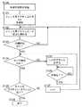
ウェア本体2の装着時のウェアフィット用アクチュエータ5の動作手順として、ウェアフィット用アクチュエータ5を1本ずつ駆動場合、及び、複数本を同時に駆動する場合を示したが、さらに別の方法として、複数のウェアフィット用アクチュエータ5を、時間差を設けて順に駆動するようにしてもよい。図46A〜図46Dは、複数のウェアフィット用アクチュエータ5を、時間差を設けて順に駆動する処理のフローチャートである。図47は、そのときの、ウェアフィット用アクチュエータ5による締め付け力としきい値との関係を示す説明図である。(
As an operation procedure of the
以下、この変形例を図46A〜図46Dを用いて説明する。まず、ステップS71で、制御部8の制御の下に、例えば1番目のウェアフィット用アクチュエータ5の駆動を開始する。このとき、例えば、制御部8の制御の下に、1番目のウェアフィット用アクチュエータ5に電圧を印加する。 Hereinafter, this modification will be described with reference to FIGS. 46A to 46D. First, in step S71, under the control of the
次いで、ステップS72で、1番目のウェアフィット用アクチュエータ5の駆動による収縮で発生した締め付け力を軸方向力センサ7A、垂直方向力センサ7Bなどのセンサ7で検出し、その大きさが第1しきい値を越えているか否かを制御部8で判定する。もし、締め付け力が、第1しきい値を越えていないと制御部8で判定すれば、ステップS73で所定時間だけ駆動を続けたのち、再度、ステップS72で、締め付け力が、第1しきい値を越えているか否かを制御部8で判定する。締め付け力が、第1しきい値を越えていると制御部8で判定すれば、ステップS74に進む。 Next, in step S72, the tightening force generated by the contraction due to the driving of the first
次いで、ステップS74で、制御部8の制御の下に、例えば2番目のウェアフィット用アクチュエータ5の駆動を開始する。これは、1番目のウェアフィット用アクチュエータ5の締め付け力がある程度以上になってから、2番目のウェアフィット用アクチュエータ5の駆動を開始することを意味している。 Next, in step S74, under the control of the
次いで、ステップS75で、1番目のウェアフィット用アクチュエータ5の駆動による収縮で発生した締め付け力を軸方向力センサ7A、垂直方向力センサ7Bなどのセンサ7で検出し、その大きさが第2しきい値を越えているか否かを制御部8で判定する。もし、締め付け力が、第2しきい値を越えていないと制御部8で判定すれば、ステップS76で所定時間だけ駆動を続けたのち、再度、ステップS75で、締め付け力が、第2しきい値を越えているか否かを制御部8で判定する。締め付け力が、第2しきい値を越えていると制御部8で判定すれば、ステップS77に進む。 Next, in step S75, the tightening force generated by the contraction due to the driving of the first
次いで、ステップS77で、制御部8の制御の下に、1番目のウェアフィット用アクチュエータ5の駆動を停止する。これにより、ステップS78で、1番目のウェアフィット用アクチュエータ5の駆動動作を終了する。これは、2番目のウェアフィット用アクチュエータ5の駆動を開始したのち、1番目のウェアフィット用アクチュエータ5の締め付け力が所定値まで到達すれば駆動を停止させることを意味している。 Next, in step S77, under the control of the
一方、ステップS79では、これらの一連のステップS71〜ステップS77までの間、2番目のウェアフィット用アクチュエータ5の駆動が開始されたか否かを制御部8で判定する。2番目のウェアフィット用アクチュエータ5の駆動が開始されていないときには、2番目のウェアフィット用アクチュエータ5の駆動が開始されるまで、待機しておく。ステップS74に連動して、2番目のウェアフィット用アクチュエータ5の駆動が開始されると、ステップS80に進む。 On the other hand, in step S79, the
ステップS80で、2番目のウェアフィット用アクチュエータ5の駆動による収縮で発生した締め付け力を軸方向力センサ7A、垂直方向力センサ7Bなどのセンサ7で検出し、その大きさが第1しきい値を越えているか否かを制御部8で判定する。もし、締め付け力が、第1しきい値を越えていないと制御部8で判定すれば、ステップS81で所定時間だけ駆動を続けたのち、再度、ステップS80で、締め付け力が、第1しきい値を越えているか否かを制御部8で判定する。締め付け力が、第1しきい値を越えていると制御部8で判定すれば、ステップS82に進む。 In step S80, the tightening force generated by the contraction caused by the driving of the second wear-
次いで、ステップS82で、制御部8の制御の下に、例えば3番目のウェアフィット用アクチュエータ5の駆動を開始する。これは、2番目のウェアフィット用アクチュエータ5の締め付け力がある程度以上になってから、3番目のウェアフィット用アクチュエータ5の駆動を開始することを意味している。 Next, in step S82, for example, the driving of the third
次いで、ステップS83で、2番目のウェアフィット用アクチュエータ5の駆動による収縮で発生した締め付け力を軸方向力センサ7A、垂直方向力センサ7Bなどのセンサ7で検出し、その大きさが第2しきい値を越えているか否かを制御部8で判定する。もし、締め付け力が、第2しきい値を越えていないと制御部8で判定すれば、ステップS84で所定時間だけ駆動を続けたのち、再度、ステップS83で、締め付け力が、第2しきい値を越えているか否かを制御部8で判定する。締め付け力が、第2しきい値を越えていると制御部8で判定すれば、ステップS85に進む。 Next, in step S83, the tightening force generated by the contraction due to the driving of the second
次いで、ステップS85で、制御部8の制御の下に、2番目のウェアフィット用アクチュエータ5の駆動を停止する。これにより、ステップS86で、2番目のウェアフィット用アクチュエータ5の駆動動作を終了する。これは、3番目のウェアフィット用アクチュエータ5の駆動を開始したのち、2番目のウェアフィット用アクチュエータ5の締め付け力が所定値まで到達すれば駆動を停止させることを意味している。 Next, in step S85, driving of the second
また、ステップS87では、これらの一連のステップS71〜ステップS86までの間、3番目のウェアフィット用アクチュエータ5の駆動が開始されたか否かを制御部8で判定する。3番目のウェアフィット用アクチュエータ5の駆動が開始されていないときには、3番目のウェアフィット用アクチュエータ5の駆動が開始されるまで、待機しておく。ステップS82に連動して、3番目のウェアフィット用アクチュエータ5の駆動が開始されると、ステップS88に進む。 In step S87, the
ステップS89で、3番目のウェアフィット用アクチュエータ5の駆動による収縮で発生した締め付け力を軸方向力センサ7A、垂直方向力センサ7Bなどのセンサ7で検出し、その大きさが第1しきい値を越えているか否かを制御部8で判定する。もし、締め付け力が、第1しきい値を越えていないと制御部8で判定すれば、ステップS90で所定時間だけ駆動を続けたのち、再度、ステップS89で、締め付け力が、第1しきい値を越えているか否かを制御部8で判定する。締め付け力が、第1しきい値を越えていると制御部8で判定すれば、ステップS91に進む。 In step S89, the tightening force generated by the contraction due to the driving of the third wear-
次いで、ステップS91で、制御部8の制御の下に、例えば4番目のウェアフィット用アクチュエータ5の駆動を開始する。これは、3番目のウェアフィット用アクチュエータ5の締め付け力がある程度以上になってから、4番目のウェアフィット用アクチュエータ5の駆動を開始することを意味している。 Next, in step S91, under the control of the
次いで、ステップS92で、3番目のウェアフィット用アクチュエータ5の駆動による収縮で発生した締め付け力でかつセンサ7で検出した締め付け力が、第2しきい値を越えているか否かを制御部8で判定する。もし、締め付け力が、第2しきい値を越えていないと制御部8で判定すれば、ステップS93で所定時間だけ駆動を続けたのち、再度、ステップS92で、締め付け力が、第2しきい値を越えているか否かを制御部8で判定する。締め付け力が、第2しきい値を越えていると制御部8で判定すれば、ステップS94に進む。 Next, in step S92, the
次いで、ステップS94で、制御部8の制御の下に、3番目のウェアフィット用アクチュエータ5の駆動を停止する。これにより、ステップS95で、3番目のウェアフィット用アクチュエータ5の駆動動作を終了する。これは、4番目のウェアフィット用アクチュエータ5の駆動を開始したのち、3番目のウェアフィット用アクチュエータ5の締め付け力が所定値まで到達すれば駆動を停止させることを意味している。 Next, in step S94, the driving of the third
以下、同様に、総数N個のウェアフィット用アクチュエータ5について、ステップS96では、S96より前の一連のステップまでの間、(N−1)番目のウェアフィット用アクチュエータ5の駆動が開始されたか否かを制御部8で判定する。(N−1)番目のウェアフィット用アクチュエータ5の駆動が開始されていないときには、(N−1)番目のウェアフィット用アクチュエータ5の駆動が開始されるまで、待機しておく。(N−1)番目のウェアフィット用アクチュエータ5の駆動が開始されると、ステップS97に進む。 Hereinafter, similarly, in step S96, the driving of the (N-1)
ステップS97で、(N−1)番目のウェアフィット用アクチュエータ5の駆動による収縮で発生した締め付け力を軸方向力センサ7A、垂直方向力センサ7Bなどのセンサ7で検出し、その大きさが第1しきい値を越えているか否かを制御部8で判定する。もし、締め付け力が、第1しきい値を越えていないと制御部8で判定すれば、ステップS98で所定時間だけ駆動を続けたのち、再度、ステップS97で、締め付け力が、第1しきい値を越えているか否かを制御部8で判定する。締め付け力が、第1しきい値を越えていると制御部8で判定すれば、ステップS99に進む。 In step S97, the tightening force generated by the contraction due to the driving of the (N-1)
次いで、ステップS99で、制御部8の制御の下に、N番目のウェアフィット用アクチュエータ5の駆動を開始する。これは、(N−1)番目のウェアフィット用アクチュエータ5の締め付け力がある程度以上になってから、N番目のウェアフィット用アクチュエータ5の駆動を開始することを意味している。 Next, in step S99, driving of the Nth wear
次いで、ステップS100で、(N−1)番目のウェアフィット用アクチュエータ5の駆動による収縮で発生した締め付け力を軸方向力センサ7A、垂直方向力センサ7Bなどのセンサ7で検出し、その大きさが第2しきい値を越えているか否かを制御部8で判定する。もし、締め付け力が、第2しきい値を越えていないと制御部8で判定すれば、ステップS101で所定時間だけ駆動を続けたのち、再度、ステップS100で、締め付け力が、第2しきい値を越えているか否かを制御部8で判定する。締め付け力が、第2しきい値を越えていると制御部8で判定すれば、ステップS102に進む。 Next, in step S100, the tightening force generated by the contraction due to the driving of the (N-1) th wear-
次いで、ステップS102で、制御部8の制御の下に、(N−1)番目のウェアフィット用アクチュエータ5の駆動を停止する。これにより、ステップS103で、(N−1)番目のウェアフィット用アクチュエータ5の駆動動作を終了する。これは、N番目のウェアフィット用アクチュエータ5の駆動を開始したのち、(N−1)番目のウェアフィット用アクチュエータ5の締め付け力が所定値まで到達すれば駆動を停止させることを意味している。 Next, in step S102, under the control of the
ステップS104では、S104より前の一連のステップまでの間、N番目のウェアフィット用アクチュエータ5の駆動が開始されたか否かを制御部8で判定する。N番目のウェアフィット用アクチュエータ5の駆動が開始されていないときには、N番目のウェアフィット用アクチュエータ5の駆動が開始されるまで、待機しておく。N番目のウェアフィット用アクチュエータ5の駆動が開始されると、ステップS105に進む。 In step S104, the
ステップS105で、N番目のウェアフィット用アクチュエータ5の駆動による収縮で発生した締め付け力を軸方向力センサ7A、垂直方向力センサ7Bなどのセンサ7で検出し、その大きさが第2しきい値を越えているか否かを制御部8で判定する。もし、締め付け力が、第2しきい値を越えていないと制御部8で判定すれば、ステップS106で所定時間だけ駆動を続けたのち、再度、ステップS105で、締め付け力が、第2しきい値を越えているか否かを制御部8で判定する。締め付け力が、第2しきい値を越えていると制御部8で判定すれば、ステップS107に進む。 In step S105, the tightening force generated by the contraction due to the driving of the Nth wear-
次いで、ステップS107で、制御部8の制御の下に、N番目のウェアフィット用アクチュエータ5の駆動を停止する。これにより、ステップS108で、N番目のウェアフィット用アクチュエータ5の駆動動作を終了する。これは、N番目すなわち最後のウェアフィット用アクチュエータ5の締め付け力が所定値まで到達すれば駆動を停止させることを意味している。 Next, in step S107, driving of the
前記した第1しきい値の例としては、所定値の80%の値とし、第2しきい値の例としては、所定値の100%の値とする。このときの駆動状態を示すグラフを図47に示す。ここでは、1本目〜3本目までのウェアフィット用アクチュエータ5が順次時間差で駆動されることが示されている。 An example of the first threshold value is 80% of the predetermined value, and an example of the second threshold value is 100% of the predetermined value. A graph showing the drive state at this time is shown in FIG. Here, it is shown that the first to third wear-
このように構成すれば、1番目からN番目のウェアフィット用アクチュエータ5まで、複数のウェアフィット用アクチュエータ5を、時間差を設けて順に駆動することができる。このような構成にすれば、多数のウェアフィット用アクチュエータ5を1本ずつ逐一駆動する場合よりも、短時間で、しわ39を発生させること無くフィットさせることができる。 If comprised in this way, the several wear
なお、本実施形態では、ウェア本体2の一端から他端に向けてフィットを行っているが、中央からフィットを開始して両端に向かってフィットを同時的に行っても良い。それにより、さらに、フィットのための時間を短縮することができる。 In this embodiment, the fitting is performed from one end to the other end of the wear
(ウェア装着動作の変形例2)
次に、ウェア本体装着時のエラー対応について変形例を示す。図37及び図38を用いて示した装着時の動作手順は、フィット用アクチュエータ5のフィットが完了した後、しわの検出を行っている。しかし、ウェア装着時において、ウェア本体2の一端から順にフィットさせていく過程でしわ等のエラーを検出し、ユーザ1にしわ伸ばし等の対応を促すようにしてもよい。(
Next, a modified example of error handling when the wear main body is mounted will be described. The operation procedure at the time of mounting shown in FIGS. 37 and 38 detects wrinkles after the fitting of the
これについて、図48を基に詳しく説明する。図48は、締め付け(フィット)動作時に、しわ39があると制御部8で判定された場合に、その領域の締め付け動作を再度やり直す動作の説明図である。図48の(1)の状態は、ウェア本体2をユーザ1が履いた状態であり、全体が緩んでいる状態である。この後、ウェア本体2の上端部の領域2g1に対応して配置されたウェアフィット用アクチュエータ5の駆動を行って締め付け状態にしたのち、当該領域のセンサ7の出力を制御部8で検出してしわ39の有無を判定する。 This will be described in detail with reference to FIG. FIG. 48 is an explanatory diagram of an operation of redoing the tightening operation in the region when the
しわ39があると制御部8で判定された場合には、図48の(2)の状態に示すように、上端部の領域2g1に配置されたウェアフィット用アクチュエータ5の駆動を停止したのち再び駆動を行って、締め付け動作のやり直しを行う。あるいは、制御部8の制御の下に、しわ39がある旨の警告を入出力装置16のスピーカ又はディスプレイ又は振動装置などにより行う。その後、ユーザ1が手でウェア本体2を引っ張るなどしてしわ39を取除くなどしたのち、再び、当該領域のセンサ7の出力を制御部8で検出してしわ39の有無を判定するようにしてもよい。このしわ取り動作は、しわが無くなるまで行ってもよいし、数回行ってもしわ39がある場合には、エラー表示を行って、アシスト動作を停止してもよい。 If the
なお、この図48では、しわ39が無いと制御部8で判定された領域のセンサ7は黒丸で示し、しわ39の有無判定を未だしていない領域のセンサ7は白丸で示している。 In FIG. 48, the
しわ39を取除くなどしたのち、当該領域のセンサ7の出力を制御部8で検出してしわ39が無いと判定されると(図48の(3)の状態を参照)、次の領域2g2での締め付け動作及びしわ39の有無判定を順次行う(図48の(4)の状態を参照)。順番に2g3、2g4の領域の締め付け及びしわ39の確認を左右の下端部2cまで行えば(図48の(5)〜(6)の状態を参照)、ウェア本体2の全体がしわ39が無い状態となる(図48の(6)の状態を参照)。 After removing the
次に、この一連の動作を図49のフローチャートを基に詳しく説明する。 Next, this series of operations will be described in detail based on the flowchart of FIG.
まず、ステップS120で、ユーザ1からのウェア本体2の脱衣の指示を制御部8で受信すれば、以下の処理を開始する。 First, in step S120, if the
次いで、ステップS121で、ウェアフィット用アクチュエータ5としてi=1番目のウェアフィット用アクチュエータ5を制御部8で選択する。 Next, in step S <b> 121, the
次いで、ステップS122で、制御部8の制御の下に、制御部8で選択されたi=1番目のウェアフィット用アクチュエータ5の駆動を開始して、i=1番目のウェアフィット用アクチュエータ5を少し収縮させて締め付けを開始する。 Next, in step S122, under the control of the
次いで、ステップS123で、i=1番目のウェアフィット用アクチュエータ5の収縮が完了したか否かを制御部8で判定する。i=1番目のウェアフィット用アクチュエータ5の収縮が完了していないと制御部8で判定すれば、ステップS122に戻る。i=1番目のウェアフィット用アクチュエータ5の収縮が完了したと制御部8で判定すれば、ステップS124に進む。 Next, in step S123, the
次いで、ステップS124で、センサ7の出力を制御部8で検出する。このとき、i=1番目のウェアフィット用アクチュエータ5が配置されている領域内のセンサ7の出力のみを制御部8で抽出して、検出電位が正常か否かを制御部8で判定する。例えば、センサ7が筋電センサの場合には、ユーザ1の動きに対して筋電信号が発生するか否かを判定する。検出電位が正常であると制御部8で判定するときは、ステップS125に進む。もし、検出電位が正常ではないと制御部8で判定するときは、ステップS128に進む。 Next, in step S124, the output of the
ステップS128では、制御部8の制御の下に、しわ39がある旨の警告を入出力装置16のスピーカ又はディスプレイ又は振動装置などにより行う。警告の仕方としては、入出力装置16のスピーカ、LED、又は無線通信機器でユーザ1の情報端末機15に通知するなどが例示できる。警告の仕方として、しわ39の発生を警告するだけでなく、センサ7の出力に基づき、しわ39が発生した領域をユーザ1に通知することもできる。 In step S128, under the control of the
次いで、ステップS129では、対策が完了したか否かを制御部8で判定する。対策が完了すれば、ステップS124に戻る。対策が完了しない場合には、警告を出し続ける。ここで、対策の例としては、しわ39がある部分をユーザ1が手で直して、しわ39を取り、全てのセンサ7を皮膚1aに接触させる方法がある。また、入出力装置16を操作して、制御部8を介して、ウェア本体2のしわ39がある部分に配置されたウェアフィット用アクチュエータ5の駆動を一旦停止したのち再度駆動して、しわ39を無くすようにする方法もある。例えば、ウェア本体2を、予め、上端部2aの領域(2g1)と、上端部2aと大腿部の付け根部2bとの間の領域(2g2)と、大腿部の付け根部2bの領域(2g3)と、左側の下端部2cの領域(2g4)と、右側の下端部2cの領域(2g4)とに分けておき、しわ39が発生した領域に対応して配置されたウェアフィット用アクチュエータ5の駆動を一旦停止したのち再度駆動して、しわ39を無くすようにすることができる。いずれかの方法を実施することにより、しわ39を無くすようにして、検出電位が正常となったことを制御部8で判定するようにしてもよい。また、ユーザ1が入出力装置16を操作して、制御部8に対策完了信号を入力するようにしてもよい。 Next, in step S129, the
ステップS125で、全てのウェアフィット用アクチュエータ5の駆動すなわち収縮が完了したか否かを制御部8で判定する。全てのウェアフィット用アクチュエータ5の収縮が完了していないと制御部8で判定すれば、ステップS127に進む。全てのウェアフィット用アクチュエータ5の収縮が完了したと制御部8で判定すれば、ステップS126に進んで終了する。 In step S125, the
ステップS127では、ウェアフィット用アクチュエータ5としてi=i+1番目のウェアフィット用アクチュエータ5を制御部8で選択したのち、ステップS122に戻る。 In step S127, the
以上のようにすると、ウェア装着時においてしわ39が発生した段階で、すぐにユーザ1がしわ39の発生に気づくことができるようになる。それにより、ユーザ1は全てのウェアフィット用アクチュエータ5の動作完了を待たずに、すぐに、しわ39を解消することができると共に、どの領域で問題が発生したかも容易に認識できるようになる。 As described above, the
(変形例)
先の実施形態では、ウェアフィット用アクチュエータ5は、全て同一の構造及び力を作用させる部材を使用しているが、これに限られるものではない。(Modification)
In the previous embodiment, the wear-
例えば、図50では、ウェア本体2の全体にわたって同一のウェアフィット用アクチュエータ5を配置し、ウェア本体2の部分によって配置密度を変えた例である。この場合は、ウェア本体2をユーザ1の部位に対して、全体的に均一に締め付け力を加えることができて、均一にフィットさせるのに適している。 For example, FIG. 50 shows an example in which the same
このように構成すれば、全てのセンサ7の接触状態を均一にすることができ、安定した測定を行うことができる。この例は、例えば、図23のウェア本体2の第1構造例45において特に有効である。 If comprised in this way, the contact state of all the
これに対して、図51では、強い力で締め付けが可能なウェアフィット用アクチュエータ5と弱い力で締め付けが可能なウェアフィット用アクチュエータ5とを使用している。一例として、収縮時に張力を100%発揮可能なウェアフィット用アクチュエータ5Cと、収縮時に張力を60%発揮可能なウェアフィット用アクチュエータ5Dとの2種類のウェアフィット用アクチュエータ5C,5Dとを配置している。具体的には、張力を100%発揮可能なウェアフィット用アクチュエータ5Cは、ウェア本体2の上端部2aと、大腿部の付け根部2bと、ウェア本体の下端部2cとに配置して、しっかりとフィットさせるようにしている。これに対して、張力を60%発揮可能なウェアフィット用アクチュエータ5Dは、ウェア本体2の上端部2aと大腿部の付け根部2bとの間の部分、及び、大腿部の付け根部2bとウェア本体の下端部2cの間の部分に配置して、やや緩めにフィットさせるようにしている。 On the other hand, in FIG. 51, the wear-
このように構成すれば、ウェアフィット用アクチュエータ5Cを使用して、アシスト用アクチュエータ6の拘束に必要な部分を重点的に固定することで位置ずれを防ぎ、それ以外の部分には、ウェアフィット用アクチュエータ5Dを使用して緩めることで、アシスト用アクチュエータ6が伸縮しやすくすることができる。この例は、例えば、図25のウェア本体2の第3構造例65において特に有効である。 If comprised in this way, using the
(変形例)
前記実施形態では、ウェア本体2の例としてパンツであったが、これに限られるものではなく、図52及び図53にそれぞれ示すように、腕1fに装着して肘1gの屈伸動作をアシストする肘用のアシストウェア4B、及び、手1hに装着して各指1jの屈伸動作をアシストする指用のアシストウェア4Cでもよい。また、図1に示すように、コントローラベルト3もウェア本体2と別に設けるものに限らず、図52に示すように、肘用のアシストウェア4Bに装着するアシストウェア本体2Bの先端部には、操作装置18を備えるようにしてもよい。(Modification)
In the above-described embodiment, the pants are an example of the wear
図52に示すように、肘用のアシストウェア4Bは、腕1fの軸方向沿いに複数のアシスト用アクチュエータ6を配置する一方、軸方向と交差する方向沿いに複数のウェアフィット用アクチュエータ5を配置している。 As shown in FIG. 52, the
また、図53に示すように、指用のアシストウェア4Cは、腕1f及び指1jの軸方向沿いに複数のアシスト用アクチュエータ6を配置する一方、軸方向と交差する方向沿いに複数のウェアフィット用アクチュエータ5を配置している。 Further, as shown in FIG. 53, the assist wear 4C for fingers includes a plurality of
なお、図52及び図53における黒色のバンド部は、ゴムベルトなどの拘束部2kである。 52 and 53, the black band portion is a restraining
なお、これら以外にも、膝、足首、足の指などにも同様に適用するようにしてもよい。 In addition to these, the present invention may be applied similarly to knees, ankles, toes, and the like.
なお、本発明を第1実施形態及び変形例に基づいて説明してきたが、本発明は、前記の第1実施形態及び変形例に限定されないのはもちろんである。以下のような場合も本発明に含まれる。 Although the present invention has been described based on the first embodiment and modifications, it is needless to say that the present invention is not limited to the first embodiment and modifications. The following cases are also included in the present invention.
前記制御部8の一部又は全部は、具体的には、マイクロプロセッサ、ROM、RAM、ハードディスクユニット、ディスプレイユニット、キーボード、マウスなどから構成されるコンピュータシステムである。前記RAM又はハードディスクユニットには、コンピュータプログラムが記憶されている。前記マイクロプロセッサが、前記コンピュータプログラムにしたがって動作することにより、各部は、その機能を達成する。ここでコンピュータプログラムは、所定の機能を達成するために、コンピュータに対する指令を示す命令コードが複数個組み合わされて構成されたものである。 Specifically, a part or all of the
例えば、ハードディスク又は半導体メモリ等の記録媒体に記録されたソフトウェア・プログラムをCPU等のプログラム実行部が読み出して実行することによって、各構成要素が実現され得る。 For example, each component can be realized by a program execution unit such as a CPU reading and executing a software program recorded on a recording medium such as a hard disk or a semiconductor memory.
なお、前記実施形態又は変形例における制御部を構成する要素の一部又は全部を実現するソフトウェアは、以下のようなプログラムである。 In addition, the software which implement | achieves a part or all of the element which comprises the control part in the said embodiment or modification is the following programs.
つまり、このプログラムは、生体の部位に装着されるアシストウェアであって、
生体に装着された場合において前記生体の筋肉の収縮方向に沿って線状に複数本配置され、伸縮駆動するアシスト用アクチュエータと、
前記アシスト用アクチュエータと交差して線状に複数本配置され、伸縮駆動するフィット用アクチュエータと、
前記アシスト用アクチュータ及び前記フィット用アクチュエータの周囲に複数配置される複数のセンサと、
前記複数のセンサの検知結果に基づき、前記アシスト用アクチュエータの駆動と、前記フィット用アクチュエータの駆動とをそれぞれ制御する制御部と、
を備えるアシストウェアの前記制御部のコンピュータにおいて実行されるプログラムであって、
前記制御部のコンピュータに対して、
前記フィット用アクチュエータの中の第1のアクチュエータを収縮させる機能と、
前記複数のセンサの中で前記第1のアクチュエータの周囲に配置された前記センサを用いて前記アシストウェアが前記生体に接触したか否かを検知させる機能と、
前記センサの検知結果から、前記第1のアクチュエータの周囲の全てが前記生体に接触したか否かを判断させる機能と、
前記第1のアクチュエータの周囲の全てが前記生体に接触したと判断した場合、前記フィット用アクチュエータの中の第2のアクチュエータを収縮させる機能とを実行させるための、アシストウェアの制御部の制御プログラムである。In other words, this program is assist wear to be worn on the body part,
A plurality of assisting actuators that are arranged linearly along the direction of contraction of the muscles of the living body when attached to the living body, and that are driven to extend and contract,
A plurality of linear actuators that intersect with the assisting actuators and are driven to extend and contract, and
A plurality of sensors arranged around the assist actuator and the fit actuator;
Based on the detection results of the plurality of sensors, a controller that controls driving of the assisting actuator and driving of the fitting actuator,
A program executed on a computer of the control unit of the assist wear comprising:
For the computer of the control unit,
A function of contracting a first actuator of the fitting actuators;
A function of detecting whether the assist wear has touched the living body using the sensor arranged around the first actuator among the plurality of sensors;
A function for determining whether or not all of the periphery of the first actuator has contacted the living body from the detection result of the sensor;
The control program of the control unit of the assist wear for executing the function of contracting the second actuator of the actuator for fitting when it is determined that all the surroundings of the first actuator are in contact with the living body It is.
また、別のプログラムとしては、生体の部位に装着されるアシストウェアであって、
前記部位に装着された場合において前記部位の筋肉の伸縮方向に沿って線状に複数本配置され、伸縮駆動するアシスト用アクチュエータと、
前記アシスト用アクチュエータと交差して線状に複数本配置され、伸縮駆動するフィット用アクチュエータと、
前記アシスト用アクチュエータの駆動と、前記フィット用アクチュエータの駆動とをそれぞれ制御する制御部と、
を備えるアシストウェアの前記制御部において実行されるプログラムであって、
前記制御部のコンピュータに対して、
前記フィット用アクチュエータを収縮駆動させる機能と、
次に、前記アシスト用アクチュエータを伸縮駆動させる機能とを実行させるための、アシストウェアの制御部の制御プログラムである。Another program is assist wear to be worn on a body part,
A plurality of assisting actuators that are arranged linearly along the direction of expansion and contraction of the muscles of the part when attached to the part, and that are driven to extend and contract,
A plurality of linear actuators that intersect with the assisting actuators and are driven to extend and contract, and
A control unit that controls driving of the assisting actuator and driving of the fitting actuator;
A program executed by the control unit of the assist wear comprising:
For the computer of the control unit,
A function of contractively driving the fitting actuator;
Next, there is a control program of a control unit of assist wear for executing a function of extending and retracting the assist actuator.
また、このプログラムは、サーバなどからダウンロードされることによって実行されてもよく、所定の記録媒体(例えば、CD−ROMなどの光ディスク、磁気ディスク、又は、半導体メモリなど)に記録されたプログラムが読み出されることによって実行されてもよい。 The program may be executed by being downloaded from a server or the like, and a program recorded on a predetermined recording medium (for example, an optical disk such as a CD-ROM, a magnetic disk, or a semiconductor memory) is read out. May be executed.
また、このプログラムを実行するコンピュータは、単数であってもよく、複数であってもよい。すなわち、集中処理を行ってもよく、あるいは分散処理を行ってもよい。 Further, the computer that executes this program may be singular or plural. That is, centralized processing may be performed, or distributed processing may be performed.
なお、本開示の前記態様を別の表現形式で、以下のように表現することもできる。すなわち、本開示の別の態様にかかるアシストウェアは、生体の部位に装着されるアシストウェアであって、
前記アシストウェア本体の少なくとも一端部の周囲に沿って線状に複数本配置され、伸縮駆動するフィット用アクチュエータと、
前記フィット用アクチュエータと交差して線状に複数本配置され、伸縮駆動するアシスト用アクチュエータと、
前記アシスト用アクチュエータの駆動と、前記フィット用アクチュエータの駆動とをそれぞれ制御する制御部と、
を備える。In addition, the said aspect of this indication can also be expressed as follows with another expression form. That is, the assist wear according to another aspect of the present disclosure is assist wear attached to a part of a living body,
A plurality of linearly arranged along the periphery of at least one end of the assist wear body, and a fitting actuator that drives to extend and contract,
A plurality of assisting actuators arranged in a line and intersecting with the fitting actuators to drive expansion and contraction,
A control unit that controls driving of the assisting actuator and driving of the fitting actuator;
Is provided.
また、このような態様においては、前記アシスト用アクチュエータは、前記部位に装着された場合において前記部位の筋肉の伸縮方向に沿って配置される、ようにしてもよい。 Moreover, in such an aspect, the assisting actuator may be arranged along the direction of expansion and contraction of the muscle of the part when the assisting actuator is attached to the part.
なお、前記様々な実施形態又は変形例のうちの任意の実施形態又は変形例を適宜組み合わせることにより、それぞれの有する効果を奏するようにすることができる。また、実施形態同士の組み合わせ又は実施例同士の組み合わせ又は実施形態と実施例との組み合わせが可能であると共に、異なる実施形態又は実施例の中の特徴同士の組み合わせも可能である。 In addition, it can be made to show the effect which each has by combining arbitrary embodiment or modification of the said various embodiment or modification suitably. In addition, combinations of the embodiments, combinations of the examples, or combinations of the embodiments and examples are possible, and combinations of features in different embodiments or examples are also possible.
本開示にかかるアシストウェア、アシストウェアの作動方法、及び、制御プログラムは、ウェアフィット用アクチュエータにより前記ウェア本体を緩く装着された状態から締め付けられた状態となり、人体に、より適切にフィットした状態となり、アシスト用アクチュエータからのアシスト力を、より適切に人体の筋肉などに作用させることが可能になる。この結果、重労働の軽減のため、上腕二等筋、背筋、大殿筋、若しくは大腿筋等をアシストすることによる重量物の持ち上げ又は運搬作業等のアシスト動作、リハビリ、筋力低下の補助のため、指の屈伸をアシストする握力アシスト又は大殿筋若しくは大腿筋等をアシストする歩行アシスト動作、マッサージのため、首、肩、若しくは腰などの周辺筋肉のアシスト動作、スキルアシストのため、全身の筋肉をアシストするゴルフスウィングのレッスン用の筋肉アシスト動作、又はトレーニングのため、筋肉の動作とは逆方向に負荷をかけて筋肉を鍛える筋肉アシスト動作など、種々の動作のアシストに利用することができる。State assisted ware according to the presentdisclosure,actuation how the assist hardware, and the control program becomes a state in which tightened from the state by wear fit actuator mounted loosely the wear body, the human body, that fits more appropriately Thus, the assist force from the assist actuator can be applied to the human muscles and the like more appropriately. As a result, in order to reduce heavy labor, assisting lifting, carrying work, etc. of heavy objects by assisting the biceps, back muscles, gluteal muscles, thigh muscles, etc. Grip strength assist to assist flexion and extension of the body, walking assist operation to assist the greater gluteus or thigh muscle, etc., assist massage of peripheral muscles such as neck, shoulders or hips for massage, assist whole body muscle for skill assist It can be used for assisting various operations such as a muscle assist operation for a golf swing lesson or a muscle assist operation for training a muscle by applying a load in the opposite direction to the muscle operation for training.
1 人体(ユーザ)
1a 皮膚
1b 筋肉
1d 脚
1e 目標筋肉
1f 腕
1g 肘
1h 手
1j 指
2,2B アシストウェア本体
2a ウェア本体の上端部
2b 大腿部の付け根部
2c ウェア本体の下端部
2d 大腿部の前側中央から腰部にかけての部分
2e 端部2a〜2c以外の他の部分
2f 部分2d以外の部分
2g 筋肉に対応する領域
2h センサ目標領域
2k 拘束部
3 コントローラベルト
3a 係合部
4 アシストウェア
4B 肘用のアシストウェア
4C 指用のアシストウェア
5 ウェアフィット用アクチュエータ
5a 電極
6,6A〜6F アシスト用アクチュエータ
7 センサ
7A 軸方向力センサ
7B 垂直方向力センサ
8 制御部
8a 記憶部
8b 演算部
8c 判定部
8d 駆動部
8e アクチュエータ選択部
9 センサ用配線
15 スマートフォンなどの情報端末機
16 入出力装置
18 操作装置
30 ゴムチューブ
31 網目状繊維
32 マッキベン型アクチュエータ
33 フランジ
34 配管
39 しわ
41 第1層
42 第2層
43 第3層
44 第4層
45 第1構造例
46 アシスト用アクチュエータ固定部
47 アシスト用アクチュエータの配線
51 第1層
52 第2層
53 第3層
55 第2構造例
56 アシスト用アクチュエータ固定部
57 アシスト用アクチュエータの配線
61 第1層
62 第2層
63 第3層
64 第4層
65 第3構造例
66 アシスト用アクチュエータ固定部
67 アシスト用アクチュエータの配線
71 第1層
72 第2層
73 第3層
75 第4構造例
76 アシスト用アクチュエータ固定部
77 アシスト用アクチュエータの配線1 Human body (user)
DESCRIPTION OF SYMBOLS 1a Skin 1b Muscle 1d Leg 1e Target muscle 1f Arm 1g Elbow 1h Hand 1j Finger 2, 2B Assist wear main body 2a Upper end part 2b of wear main part 2c Bottom part of wear main part 2c Lower end part 2d of wear main body From front center of thigh 2e other than the end portions 2a to 2c 2f other than the portion 2d 2g other than the portion 2d 2g corresponding to the muscle 2h sensor target region 2k restraint unit 3 controller belt 3a engagement unit 4 assist wear 4B assist wear for elbow 4C Finger assist wear 5 Wear fit actuator 5a Electrodes 6, 6A to 6F Assist actuator 7 Sensor 7A Axial force sensor 7B Vertical force sensor 8 Control unit 8a Storage unit 8b Calculation unit 8c Determination unit 8d Drive unit 8e Actuator Selection unit 9 Sensor wiring 15 Information terminal 16 such as a smartphone Device 18 Operating device 30 Rubber tube 31 Mesh fiber 32 Macchiben type actuator 33 Flange 34 Pipe 39 Wrinkle 41 First layer 42 Second layer 43 Third layer 44 Fourth layer 45 First structural example 46 Assist actuator fixing portion 47 Assist Actuator wiring 51 First layer 52 Second layer 53 Third layer 55 Second structural example 56 Assist actuator fixing portion 57 Assist actuator wiring 61 First layer 62 Second layer 63 Third layer 64 Fourth layer 65 Third Structure Example 66 Assist Actuator Fixing Section 67 Assist Actuator Wiring 71 First Layer 72 Second Layer 73 Third Layer 75 Fourth Structure Example 76 Assist Actuator Fixing Section 77 Assist Actuator Wiring
Claims (19)
Translated fromJapanese前記部位に装着された場合において前記部位の筋肉の伸縮方向に沿って線状に複数本配置され、伸縮駆動して前記筋肉の動きをアシストするアシスト用アクチュエータと、
前記アシスト用アクチュエータと交差して線状に複数本配置され、伸縮駆動するフィット用アクチュエータと、
前記アシスト用アクチュエータの駆動と、前記フィット用アクチュエータの駆動とをそれぞれ制御する制御部と、
を備え、
前記制御部は、前記フィット用アクチュエータを駆動することによって前記フィット用アクチュエータを収縮させ、前記部位に前記アシスト用アクチュエータを密着固定し、前記フィット用アクチュエータを駆動することによって前記フィット用アクチュエータを伸張させ、前記密着固定を開放するアシストウェア。Assist wear to be worn on the body part,
A plurality of linearly arranged along the direction of expansion and contraction of the muscles of the part when mounted on the part, and an assisting actuator that assists the movement of the muscle by extending and contracting,
A plurality of linear actuators that intersect with the assisting actuators and are driven to extend and contract, and
A control unit that controls driving of the assisting actuator and driving of the fitting actuator;
Equipped witha,
The control unit contracts the fit actuator by driving the fit actuator, closely contacts and fixes the assist actuator to the portion, and extends the fit actuator by driving the fit actuator. , assist wearyou open the tightly fixed.
前記フィット用アクチュエータは、前記アシストウェア本体の前記一端部と前記他端部との少なくともいずれか一方の端部の周囲方向に沿って線状に複数本配置される、
請求項1に記載のアシストウェア。The assisting actuator is arranged in a plurality of lines along the direction from one end of the assist wear main body to the other end,
A plurality of the fit actuators are arranged in a line along the circumferential direction of at least one of the one end and the other end of the assist wear body.
The assist wear according to claim 1.
請求項1に記載のアシストウェア。When the fitting actuator is attached to the part, a plurality of the actuators are arranged linearly along the circumferential direction of the part.
The assist wear according to claim 1.
前記制御部は、前記センサからの検知結果に基づき、前記フィット用アクチュエータの駆動を制御する、
請求項1から3のいずれか1つに記載のアシストウェア。A plurality of the assist wears are arranged at or around the positions where the assist actuators and the fit actuators are arranged, respectively, and detect whether or not the assist wear contacts the living body. The sensor is further provided,
The control unit controls driving of the fitting actuator based on a detection result from the sensor.
The assist wear according to any one of claims 1 to 3.
前記制御部は、前記筋電センサからの検知結果に基づき、前記アシスト用アクチュエータの駆動を制御する、
請求項4に記載のアシストウェア。The sensor is a myoelectric sensor that detects a voltage generated when moving the muscle,
The control unit controls driving of the assisting actuator based on a detection result from the myoelectric sensor.
The assist wear according to claim4 .
請求項4又は5に記載のアシストウェア。The density of arranging the sensor in a region corresponding to the muscle in the part is larger than the density of arranging the sensor in a region other than the region corresponding to the muscle.
The assist wear according to claim4 or 5 .
請求項4から6のいずれか1つに記載のアシストウェア。The control unit drives and controls the assist actuator close to the sensor arranged in a region corresponding to the muscle among the assist actuators based on detection results of the plurality of sensors.
The assist wear according to any one of claims4 to 6 .
請求項1から7のいずれか1つに記載のアシストウェア。The density of arranging the assisting actuator in a region corresponding to the muscle in the region is larger than the density of arranging the assisting actuator in a region other than the region corresponding to the muscle.
The assist wear according to any one of claims 1 to7 .
請求項1から8のいずれか1つに記載のアシストウェア。The density of arranging the fit actuator in a region corresponding to the end of the assist wear body is greater than the density of arranging the fit actuator in a region other than the region corresponding to the end.
The assist wear according to any one of claims 1 to8 .
前記複数のフィット用アクチュエータの第1のアクチュエータを収縮させると、前記複数のセンサの中で前記第1のアクチュエータの配置位置又は周囲に配置された前記センサの検知結果から、前記第1のアクチュエータの配置位置又は周囲の全てが前記生体に接触したか否かを判断し、
前記第1のアクチュエータの配置位置又は周囲の全てが前記生体に接触したと判断した場合、前記複数のフィット用アクチュエータの第2のアクチュエータを収縮させる、
請求項4から9のいずれか1つに記載のアシストウェア。The controller is
When the first actuators of the plurality of fit actuators are contracted, the detection results of the sensors disposed at or around the positions of the first actuators among the plurality of sensors are detected. Determine whether the placement position or all of the surroundings have contacted the living body,
When it is determined that the arrangement position of the first actuator or all of the surroundings are in contact with the living body, the second actuator of the plurality of fitting actuators is contracted.
The assist wear according to any one of claims4 to 9 .
請求項10に記載のアシストウェア。The second actuator is disposed adjacent to the first actuator;
The assist wear according to claim10 .
請求項10又は11に記載のアシストウェア。The control unit contracts the fitting actuator in order from one end portion in the axial direction of the assist wear main body toward the other end portion.
The assist wear according to claim10 or 11 .
前記制御部は、
前記複数のセンサの中で前記第1のアクチュエータの配置位置又は周囲に配置された前記センサの検知結果から、前記第1のアクチュエータの配置位置又は周囲の全てが前記生体に接触していないと判断した場合、前記通知部を用いて前記アシストウェアが前記生体に接触していない旨を通知する、
請求項10から12のいずれか1つに記載のアシストウェア。The assist wear further includes a notification unit,
The controller is
Based on the detection results of the sensors disposed at or around the first actuator among the plurality of sensors, it is determined that all of the positions or the surroundings of the first actuator are not in contact with the living body. If not, using the notification unit to notify that the assist wear is not in contact with the living body,
The assist wear according to any one of claims10 to 12 .
請求項13に記載のアシストウェア。The control unit generates vibration by extending and contracting the first actuator together with the notification by the notification unit.
The assist wear according to claim13 .
請求項1から14のいずれか1つに記載のアシストウェア。The fitting actuator is a linear actuator that contracts by application of heat.
The assist wear according to any one of claims 1 to14 .
請求項1から14のいずれか1つに記載のアシストウェア。The fitting actuator is a linear pneumatic actuator that expands and contracts by adjusting the air pressure.
The assist wear according to any one of claims 1 to14 .
始めに前記フィット用アクチュエータを収縮駆動させ、前記フィット用アクチュエータの収縮駆動完了後に前記アシスト用アクチュエータを伸縮駆動させる、
請求項1から16のいずれか1つに記載のアシストウェア。The controller is
First, the fitting actuator is contracted and driven, and the assisting actuator is expanded and contracted after the fitting actuator is contracted.
The assist wear according to any one of claims 1 to16 .
前記アシスト用アクチュエータと交差して線状に複数本配置され、伸縮駆動するフィット用アクチュエータと、
前記アシスト用アクチュータ及び前記フィット用アクチュエータの周囲に複数配置される複数のセンサと、
前記複数のセンサの検知結果に基づき、前記アシスト用アクチュエータの駆動と、前記フィット用アクチュエータの駆動とをそれぞれ制御する制御部と、
を備えるアシストウェアの作動方法であって、
前記制御部が、
前記フィット用アクチュエータの中の第1のアクチュエータを収縮させ、
前記複数のセンサの中で前記第1のアクチュエータの周囲に配置された前記センサを用いて前記アシストウェアが前記生体に接触したか否かを検知させ、
前記センサの検知結果から、前記第1のアクチュエータの周囲の全てが前記生体に接触したか否かを判断させ、
前記第1のアクチュエータの周囲の全てが前記生体に接触したと判断した場合、前記フィット用アクチュエータの中の第2のアクチュエータを収縮させるように制御する、
アシストウェアの作動方法。A plurality of assisting actuators that are linearly arranged along the contraction direction of the muscles of the living body when attached to the living body and that are driven to extend and contract to assist the movement of the muscles;
A plurality of linear actuators that intersect with the assisting actuators and are driven to extend and contract, and
A plurality of sensors arranged around the assist actuator and the fit actuator;
Based on the detection results of the plurality of sensors, a controller that controls driving of the assisting actuator and driving of the fitting actuator,
An assist wear operating method comprising:
The control unit is
Contracting a first actuator of the fitting actuators;
Using the sensors arranged around the first actuator among the plurality of sensors to detect whether the assist wear has touched the living body,
From the detection result of the sensor, it is determined whether or not everything around the first actuator has contacted the living body,
When it is determined that the entire periphery of the first actuator has contacted the living body, the second actuator in the fitting actuator is controlled to contract.
The operation method of assist wear.
前記アシスト用アクチュエータと交差して線状に複数本配置され、伸縮駆動するフィット用アクチュエータと、
前記アシスト用アクチュータ及び前記フィット用アクチュエータの周囲に複数配置される複数のセンサと、
前記複数のセンサの検知結果に基づき、前記アシスト用アクチュエータの駆動と、前記フィット用アクチュエータの駆動とをそれぞれ制御する制御部と、
を備えるアシストウェアの前記制御部のコンピュータにおいて実行されるプログラムであって、
前記制御部のコンピュータに対して、
前記フィット用アクチュエータの中の第1のアクチュエータを収縮させる機能と、
前記複数のセンサの中で前記第1のアクチュエータの周囲に配置された前記センサを用いて前記アシストウェアが前記生体に接触したか否かを検知させる機能と、
前記センサの検知結果から、前記第1のアクチュエータの周囲の全てが前記生体に接触したか否かを判断させる機能と、
前記第1のアクチュエータの周囲の全てが前記生体に接触したと判断した場合、前記フィット用アクチュエータの中の第2のアクチュエータを収縮させる機能とを実行させる、 アシストウェアの制御部の制御プログラム。A plurality of assisting actuators that are arranged linearly along the direction of contraction of the muscles of the living body when attached to the living body, and that are driven to extend and contract,
A plurality of linear actuators that intersect with the assisting actuators and are driven to extend and contract, and
A plurality of sensors arranged around the assist actuator and the fit actuator;
Based on the detection results of the plurality of sensors, a controller that controls driving of the assisting actuator and driving of the fitting actuator,
A program executed on a computer of the control unit of the assist wear comprising:
For the computer of the control unit,
A function of contracting a first actuator of the fitting actuators;
A function of detecting whether the assist wear has touched the living body using the sensor arranged around the first actuator among the plurality of sensors;
A function for determining whether or not all of the periphery of the first actuator has contacted the living body from the detection result of the sensor;
The control program of the control part of assistware which performs the function to contract the 2nd actuator in the actuator for a fit, when it is judged that all the circumference | surroundings of the said 1st actuator contacted the said biological body.
Priority Applications (4)
| Application Number | Priority Date | Filing Date | Title |
|---|---|---|---|
| JP2015014663AJP6489422B2 (en) | 2015-01-28 | 2015-01-28 | Assist wear, assist wear operating method, and control program |
| CN201510992696.5ACN105816301B (en) | 2015-01-28 | 2015-12-24 | Auxiliary suit, control method of the control unit of the assist suit |
| US14/988,871US10561565B2 (en) | 2015-01-28 | 2016-01-06 | Assist garment, method for controlling controller of assist garment, and recording medium |
| US16/728,354US11445769B2 (en) | 2015-01-28 | 2019-12-27 | Assist garment, method for controlling controller of assist garment, and recording medium |
Applications Claiming Priority (1)
| Application Number | Priority Date | Filing Date | Title |
|---|---|---|---|
| JP2015014663AJP6489422B2 (en) | 2015-01-28 | 2015-01-28 | Assist wear, assist wear operating method, and control program |
Publications (2)
| Publication Number | Publication Date |
|---|---|
| JP2016137146A JP2016137146A (en) | 2016-08-04 |
| JP6489422B2true JP6489422B2 (en) | 2019-03-27 |
Family
ID=56433918
Family Applications (1)
| Application Number | Title | Priority Date | Filing Date |
|---|---|---|---|
| JP2015014663AActiveJP6489422B2 (en) | 2015-01-28 | 2015-01-28 | Assist wear, assist wear operating method, and control program |
Country Status (3)
| Country | Link |
|---|---|
| US (2) | US10561565B2 (en) |
| JP (1) | JP6489422B2 (en) |
| CN (1) | CN105816301B (en) |
Families Citing this family (38)
| Publication number | Priority date | Publication date | Assignee | Title |
|---|---|---|---|---|
| US10611020B2 (en) | 2013-12-19 | 2020-04-07 | Roam Robotics Inc. | Pneumatic exomuscle system and method |
| CN105902367B (en)* | 2015-02-19 | 2020-02-07 | 松下知识产权经营株式会社 | Assist garment and control method for control unit of assist garment |
| CN105902363B (en)* | 2015-02-19 | 2020-02-07 | 松下知识产权经营株式会社 | Assist garment and control method for control unit of assist garment |
| US10660382B2 (en)* | 2015-02-27 | 2020-05-26 | Honeywell Safety Products Usa, Inc. | Apparatus, systems and methods for optimizing and masking compression in a biosensing garment |
| WO2016160624A1 (en) | 2015-03-27 | 2016-10-06 | Other Lab Llc | Lower-leg exoskeleton system and method |
| JP7020919B2 (en) | 2015-05-21 | 2022-02-16 | アザー ラブ リミテッド ライアビリティ カンパニー | Systems and methods for heat-adaptive materials |
| CA3000972A1 (en)* | 2015-10-05 | 2017-04-13 | Tactile Systems Technology, Inc. | Head and neck compression garment |
| EP3405152B1 (en) | 2016-01-21 | 2022-03-30 | Tactile Systems Technology, Inc. | Compression garment system |
| JP6832530B2 (en)* | 2016-09-30 | 2021-02-24 | パナソニックIpマネジメント株式会社 | Assist system, assist method and computer program |
| US11036295B2 (en) | 2016-11-23 | 2021-06-15 | Microsoft Technology Licensing, Llc | Electrostatic slide clutch |
| JP2018114025A (en)* | 2017-01-16 | 2018-07-26 | 株式会社東芝 | Operation support device and data collection method |
| ES2969892T3 (en) | 2017-02-03 | 2024-05-23 | Roam Robotics Inc | System and method for user intent recognition |
| USD839484S1 (en) | 2017-02-28 | 2019-01-29 | Tactile Systems Technology, Inc. | Head Garment |
| JP6904731B2 (en)* | 2017-03-01 | 2021-07-21 | 株式会社Zozo | Size measuring device, management server, user terminal and size measuring system |
| US11033450B2 (en) | 2017-04-13 | 2021-06-15 | Roam Robotics Inc. | Leg exoskeleton system and method |
| EP3646843B1 (en)* | 2017-06-29 | 2022-01-19 | NEOFECT Co., Ltd. | Body movement assistance device |
| JP6967717B2 (en)* | 2017-07-28 | 2021-11-17 | パナソニックIpマネジメント株式会社 | Assist device and how to operate the assist device |
| IL272623B2 (en) | 2017-08-29 | 2024-12-01 | Roam Robotics Inc | System and method for detecting semi-guided intent |
| US10780012B2 (en)* | 2017-08-29 | 2020-09-22 | Roam Robotics Inc. | Exoskeleton fit evaluation system and method |
| WO2019090339A1 (en) | 2017-11-06 | 2019-05-09 | Tactile Systems Technology, Inc. | Compression garment systems |
| WO2019108655A1 (en)* | 2017-11-28 | 2019-06-06 | Seismic Holdings, Inc. | Exosuit systems and methods |
| US20200375270A1 (en)* | 2017-11-29 | 2020-12-03 | Regents Of The University Of Minnesota | Active fabrics, garments, and materials |
| JP7253761B2 (en)* | 2017-12-08 | 2023-04-07 | 国立大学法人東海国立大学機構 | Active bodies and movement aids |
| US11023047B2 (en) | 2018-05-01 | 2021-06-01 | Microsoft Technology Licensing, Llc | Electrostatic slide clutch with bidirectional drive circuit |
| US10852825B2 (en) | 2018-09-06 | 2020-12-01 | Microsoft Technology Licensing, Llc | Selective restriction of skeletal joint motion |
| US20200107779A1 (en)* | 2018-10-05 | 2020-04-09 | Chang Ming Yang | Sensing system utilizing multifunctional fabric, method, and object |
| US10860102B2 (en) | 2019-05-08 | 2020-12-08 | Microsoft Technology Licensing, Llc | Guide for supporting flexible articulating structure |
| US11054905B2 (en)* | 2019-05-24 | 2021-07-06 | Microsoft Technology Licensing, Llc | Motion-restricting apparatus with common base electrode |
| US11061476B2 (en) | 2019-05-24 | 2021-07-13 | Microsoft Technology Licensing, Llc | Haptic feedback apparatus |
| EP4072498B1 (en) | 2019-12-13 | 2025-08-27 | Roam Robotics Inc. | Powered device to benefit a wearer during skiing |
| IL295817A (en) | 2020-02-25 | 2022-10-01 | Roam Robotics Inc | Fluidic actuator systems and methods for mobile robots |
| US12023292B2 (en)* | 2020-03-30 | 2024-07-02 | Regents Of The University Of Minnesota | Dynamic anchoring using localized active compression |
| WO2021243064A1 (en) | 2020-05-27 | 2021-12-02 | Roam Robotics Inc. | Modular exoskeleton systems and methods |
| WO2022027248A1 (en)* | 2020-08-04 | 2022-02-10 | Huawei Technologies Co., Ltd. | Haptic feedback arrangement |
| JP2024534808A (en) | 2021-08-17 | 2024-09-26 | ローム ロボティクス インコーポレイテッド | Maritime Applications for Mobile Robots |
| CN119384340A (en)* | 2022-04-29 | 2025-01-28 | 丹尼森科技有限公司 | Garment components designed to trigger, facilitate or resist movement |
| WO2024119406A1 (en)* | 2022-12-07 | 2024-06-13 | 深圳市韶音科技有限公司 | Wearable device |
| WO2024180458A1 (en)* | 2023-02-27 | 2024-09-06 | Dennisson Technologies Limited | Actuator assembly |
Family Cites Families (41)
| Publication number | Priority date | Publication date | Assignee | Title |
|---|---|---|---|---|
| US20020061692A1 (en)* | 1996-10-17 | 2002-05-23 | Helge G. Steckmann | Flat composite fabric with memory metal and its applications |
| US6741911B2 (en)* | 2000-09-20 | 2004-05-25 | John Castle Simmons | Natural robot control |
| CN2533826Y (en)* | 2001-07-16 | 2003-02-05 | 宗刚 | Multifunction combined space body-building orthopedic clothes |
| JP4196058B2 (en)* | 2001-12-28 | 2008-12-17 | パナソニック電工株式会社 | Massage machine equipped with actuator and sphygmomanometer equipped with the actuator |
| SG103371A1 (en)* | 2001-12-28 | 2004-04-29 | Matsushita Electric Works Ltd | Wearable human motion applicator |
| JP4165184B2 (en) | 2002-10-28 | 2008-10-15 | 松下電工株式会社 | Actuator |
| US7725175B2 (en)* | 2002-12-04 | 2010-05-25 | Kinetic Muscles, Inc. | System and method for neuromuscular reeducation |
| JP4542036B2 (en)* | 2003-03-28 | 2010-09-08 | 学校法人東京理科大学 | Wearable joint drive |
| CN1838933B (en)* | 2003-08-21 | 2010-12-08 | 国立大学法人筑波大学 | Wearable motion assistance device, method for controlling wearable motion assistance device, and control program |
| WO2005045112A1 (en)* | 2003-11-07 | 2005-05-19 | Koninklijke Philips Electronics, N.V. | Controllable surface area fabric |
| ITMI20041810A1 (en)* | 2004-09-22 | 2004-12-22 | Sports & Supports Ltd | "SANITARY ITEM, EVEN FOR SPORTS USE, AND RELATED PRODUCTION METHOD" |
| US20060122544A1 (en)* | 2004-12-03 | 2006-06-08 | Gary Ciluffo | Therapeutic "smart" fabric garment including support hose, body garments, and athletic wear |
| JP4426432B2 (en)* | 2004-12-17 | 2010-03-03 | 本田技研工業株式会社 | Auxiliary moment control method for leg exercise assistive device |
| US7896825B2 (en)* | 2005-06-17 | 2011-03-01 | Bridgepoint Medical, Inc. | Medical compression devices and methods |
| JP2007068794A (en)* | 2005-09-07 | 2007-03-22 | Okayama Univ | Fluid actuator, fluid actuator manufacturing method, muscle force assisting device equipped with fluid actuator, and restraint tool composed of fluid actuator |
| CN101282696B (en)* | 2005-10-11 | 2012-12-05 | 松下电器产业株式会社 | Motion assistance apparatus and method |
| KR100772908B1 (en)* | 2006-05-15 | 2007-11-05 | 삼성전자주식회사 | Muscle exercise aids |
| JP5098245B2 (en)* | 2006-08-01 | 2012-12-12 | ソニー株式会社 | Actuator and manufacturing method thereof |
| US7976924B2 (en)* | 2007-02-03 | 2011-07-12 | Raytheon Company | Active garment materials |
| JP5079458B2 (en)* | 2007-11-07 | 2012-11-21 | アクティブリンク株式会社 | Operation support device |
| WO2009114676A1 (en)* | 2008-03-13 | 2009-09-17 | Carolon Company | Compression adjustable fabric and garments |
| US20110166491A1 (en)* | 2008-09-10 | 2011-07-07 | University Of Tsukuba | Biological signal measuring wearing device and wearable motion assisting apparatus |
| JP5472680B2 (en)* | 2009-04-09 | 2014-04-16 | 国立大学法人 筑波大学 | Wearable motion assist device |
| US20150088043A1 (en)* | 2009-07-15 | 2015-03-26 | President And Fellows Of Harvard College | Actively controlled wearable orthotic devices and active modular elastomer sleeve for wearable orthotic devices |
| EP2453850A2 (en)* | 2009-07-15 | 2012-05-23 | President and Fellows of Harvard College | Actively controlled orthotic devices |
| JP2011036558A (en)* | 2009-08-17 | 2011-02-24 | Konica Minolta Holdings Inc | Active device for joint |
| US8257289B2 (en)* | 2010-02-03 | 2012-09-04 | Tyco Healthcare Group Lp | Fitting of compression garment |
| CN102078228A (en)* | 2010-12-30 | 2011-06-01 | 霍启英 | Intelligent mechanical leg |
| WO2013006845A2 (en)* | 2011-07-07 | 2013-01-10 | Leib Roger Kenneth | Chair, frame and lifting garment useful for patients |
| JP2013146328A (en)* | 2012-01-18 | 2013-08-01 | Seiko Epson Corp | Device for supporting operation |
| US20150366504A1 (en)* | 2014-06-20 | 2015-12-24 | Medibotics Llc | Electromyographic Clothing |
| US9303717B2 (en)* | 2012-07-11 | 2016-04-05 | The United States Of America As Represented By The Secretary Of The Army | Rate-responsive, stretchable devices |
| JP6074791B2 (en)* | 2012-09-06 | 2017-02-08 | 国立大学法人信州大学 | Elastic clothing |
| US9351900B2 (en)* | 2012-09-17 | 2016-05-31 | President And Fellows Of Harvard College | Soft exosuit for assistance with human motion |
| JP2014087636A (en)* | 2012-10-02 | 2014-05-15 | Nikon Corp | Walking support device |
| JP6379481B2 (en) | 2012-12-14 | 2018-08-29 | 株式会社ニコン | Auxiliary tools |
| US9775763B2 (en)* | 2012-12-19 | 2017-10-03 | Intel Corporation | Adaptive exoskeleton, control system and methods using the same |
| CN205521410U (en)* | 2013-03-15 | 2016-08-31 | Sri国际公司 | Programmable body augmentation system and platform for body augmentation |
| CN108670195B (en)* | 2013-05-31 | 2022-05-10 | 哈佛大学校长及研究员协会 | Soft Robotic Armor for Assisting Human Movement |
| US20160120734A1 (en)* | 2014-10-30 | 2016-05-05 | Elwha Llc | Garment system including at least one sensor and at least one actuator responsive to the sensor and related methods |
| US9687404B2 (en)* | 2014-08-26 | 2017-06-27 | Elwha Llc | Garment system including at least one muscle or joint activity sensor and at least one actuator responsive to the sensor and related methods |
- 2015
- 2015-01-28JPJP2015014663Apatent/JP6489422B2/enactiveActive
- 2015-12-24CNCN201510992696.5Apatent/CN105816301B/enactiveActive
- 2016
- 2016-01-06USUS14/988,871patent/US10561565B2/enactiveActive
- 2019
- 2019-12-27USUS16/728,354patent/US11445769B2/enactiveActive
Also Published As
| Publication number | Publication date |
|---|---|
| CN105816301B (en) | 2020-08-28 |
| US20160213548A1 (en) | 2016-07-28 |
| CN105816301A (en) | 2016-08-03 |
| US10561565B2 (en) | 2020-02-18 |
| JP2016137146A (en) | 2016-08-04 |
| US11445769B2 (en) | 2022-09-20 |
| US20200138663A1 (en) | 2020-05-07 |
Similar Documents
| Publication | Publication Date | Title |
|---|---|---|
| JP6489422B2 (en) | Assist wear, assist wear operating method, and control program | |
| CN105902367B (en) | Assist garment and control method for control unit of assist garment | |
| CN105902363B (en) | Assist garment and control method for control unit of assist garment | |
| US10556335B2 (en) | Wearable robot and method for controlling the same | |
| JP7142254B2 (en) | Assist device, operating method and program for assist device | |
| CN105873555B (en) | joint movement aids | |
| JP7142252B2 (en) | Assist device, operating method and program for assist device | |
| JP7065369B2 (en) | Assist device, operation method and program of assist device | |
| KR20210050636A (en) | Exercise support method and exercise support apparatus | |
| JP7142253B2 (en) | Assist device, operating method and program for assist device | |
| JP2014087636A (en) | Walking support device | |
| JP6229660B2 (en) | Auxiliary tool | |
| JP2019081248A (en) | Assist device, assist method and program | |
| JP6587452B2 (en) | Massage equipment | |
| JP7142255B2 (en) | Assist device, operating method and program for assist device | |
| JP7174919B2 (en) | Assist device, operating method and program for assist device | |
| JP6094209B2 (en) | Operation assist device and program for operation assist control | |
| KR101822946B1 (en) | Wearable robot with flexible strap | |
| JP5879976B2 (en) | Operation assist device and program for operation assist control | |
| JP5882696B2 (en) | Operation assist device and program for operation assist control | |
| JP6544613B1 (en) | Assist device, assist method and program | |
| HK1095509A1 (en) | Wearable action-assist device, and method and program for controlling wearable action-assist device |
Legal Events
| Date | Code | Title | Description |
|---|---|---|---|
| A621 | Written request for application examination | Free format text:JAPANESE INTERMEDIATE CODE: A621 Effective date:20170825 | |
| A977 | Report on retrieval | Free format text:JAPANESE INTERMEDIATE CODE: A971007 Effective date:20180531 | |
| A131 | Notification of reasons for refusal | Free format text:JAPANESE INTERMEDIATE CODE: A131 Effective date:20180605 | |
| A521 | Request for written amendment filed | Free format text:JAPANESE INTERMEDIATE CODE: A523 Effective date:20180727 | |
| A131 | Notification of reasons for refusal | Free format text:JAPANESE INTERMEDIATE CODE: A131 Effective date:20181106 | |
| A521 | Request for written amendment filed | Free format text:JAPANESE INTERMEDIATE CODE: A523 Effective date:20181225 | |
| TRDD | Decision of grant or rejection written | ||
| A01 | Written decision to grant a patent or to grant a registration (utility model) | Free format text:JAPANESE INTERMEDIATE CODE: A01 Effective date:20190129 | |
| A61 | First payment of annual fees (during grant procedure) | Free format text:JAPANESE INTERMEDIATE CODE: A61 Effective date:20190214 | |
| R151 | Written notification of patent or utility model registration | Ref document number:6489422 Country of ref document:JP Free format text:JAPANESE INTERMEDIATE CODE: R151 |