JP6487575B2 - Power adapter - Google Patents
Power adapterDownload PDFInfo
- Publication number
- JP6487575B2 JP6487575B2JP2017557436AJP2017557436AJP6487575B2JP 6487575 B2JP6487575 B2JP 6487575B2JP 2017557436 AJP2017557436 AJP 2017557436AJP 2017557436 AJP2017557436 AJP 2017557436AJP 6487575 B2JP6487575 B2JP 6487575B2
- Authority
- JP
- Japan
- Prior art keywords
- voltage
- charging
- terminal
- power adapter
- unit
- Prior art date
- Legal status (The legal status is an assumption and is not a legal conclusion. Google has not performed a legal analysis and makes no representation as to the accuracy of the status listed.)
- Active
Links
- 238000007600chargingMethods0.000claimsdescription584
- 238000005070samplingMethods0.000claimsdescription139
- 230000010349pulsationEffects0.000claimsdescription69
- 238000004804windingMethods0.000claimsdescription40
- 230000015572biosynthetic processEffects0.000claimsdescription18
- 238000003786synthesis reactionMethods0.000claimsdescription18
- 238000002955isolationMethods0.000claimsdescription17
- 238000001514detection methodMethods0.000claimsdescription13
- 230000002194synthesizing effectEffects0.000claimsdescription6
- 238000000034methodMethods0.000description69
- 230000006854communicationEffects0.000description58
- 238000004891communicationMethods0.000description58
- 230000008569processEffects0.000description46
- WHXSMMKQMYFTQS-UHFFFAOYSA-NLithiumChemical compound[Li]WHXSMMKQMYFTQS-UHFFFAOYSA-N0.000description24
- 229910052744lithiumInorganic materials0.000description24
- 239000003990capacitorSubstances0.000description22
- 230000007175bidirectional communicationEffects0.000description20
- 238000010586diagramMethods0.000description15
- 230000010287polarizationEffects0.000description14
- 230000008021depositionEffects0.000description12
- 230000000694effectsEffects0.000description12
- 230000020169heat generationEffects0.000description12
- 238000010891electric arcMethods0.000description10
- 230000006870functionEffects0.000description8
- 238000010280constant potential chargingMethods0.000description6
- 230000005611electricityEffects0.000description6
- 230000004044responseEffects0.000description6
- 230000008859changeEffects0.000description5
- 238000006243chemical reactionMethods0.000description4
- 230000008878couplingEffects0.000description4
- 238000010168coupling processMethods0.000description4
- 238000005859coupling reactionMethods0.000description4
- 230000007423decreaseEffects0.000description4
- 206010048669Terminal stateDiseases0.000description3
- 238000010277constant-current chargingMethods0.000description3
- 238000001914filtrationMethods0.000description3
- 238000003860storageMethods0.000description3
- 230000002159abnormal effectEffects0.000description2
- 230000002457bidirectional effectEffects0.000description2
- 238000013461designMethods0.000description2
- 238000004519manufacturing processMethods0.000description2
- 239000000463materialSubstances0.000description2
- 238000011160researchMethods0.000description2
- 230000001360synchronised effectEffects0.000description2
- 230000005856abnormalityEffects0.000description1
- 238000009825accumulationMethods0.000description1
- 230000009471actionEffects0.000description1
- 230000003213activating effectEffects0.000description1
- 230000000712assemblyEffects0.000description1
- 238000000429assemblyMethods0.000description1
- 230000033228biological regulationEffects0.000description1
- 238000004364calculation methodMethods0.000description1
- 239000002131composite materialSubstances0.000description1
- 239000012141concentrateSubstances0.000description1
- 238000012937correctionMethods0.000description1
- 230000007547defectEffects0.000description1
- 238000004146energy storageMethods0.000description1
- 238000005516engineering processMethods0.000description1
- 230000003993interactionEffects0.000description1
- 230000002427irreversible effectEffects0.000description1
- 238000005304joiningMethods0.000description1
- 238000012986modificationMethods0.000description1
- 230000004048modificationEffects0.000description1
- 238000012544monitoring processMethods0.000description1
- 230000002265preventionEffects0.000description1
- 238000012545processingMethods0.000description1
- 239000004065semiconductorSubstances0.000description1
- 238000000926separation methodMethods0.000description1
- 239000007787solidSubstances0.000description1
- 230000005654stationary processEffects0.000description1
- 230000002459sustained effectEffects0.000description1
Images


Classifications
- H—ELECTRICITY
- H04—ELECTRIC COMMUNICATION TECHNIQUE
- H04M—TELEPHONIC COMMUNICATION
- H04M19/00—Current supply arrangements for telephone systems
- H—ELECTRICITY
- H02—GENERATION; CONVERSION OR DISTRIBUTION OF ELECTRIC POWER
- H02J—CIRCUIT ARRANGEMENTS OR SYSTEMS FOR SUPPLYING OR DISTRIBUTING ELECTRIC POWER; SYSTEMS FOR STORING ELECTRIC ENERGY
- H02J7/00—Circuit arrangements for charging or depolarising batteries or for supplying loads from batteries
- H02J7/007—Regulation of charging or discharging current or voltage
- G—PHYSICS
- G01—MEASURING; TESTING
- G01R—MEASURING ELECTRIC VARIABLES; MEASURING MAGNETIC VARIABLES
- G01R31/00—Arrangements for testing electric properties; Arrangements for locating electric faults; Arrangements for electrical testing characterised by what is being tested not provided for elsewhere
- G01R31/28—Testing of electronic circuits, e.g. by signal tracer
- G01R31/2851—Testing of integrated circuits [IC]
- G01R31/2855—Environmental, reliability or burn-in testing
- G01R31/2872—Environmental, reliability or burn-in testing related to electrical or environmental aspects, e.g. temperature, humidity, vibration, nuclear radiation
- G01R31/2874—Environmental, reliability or burn-in testing related to electrical or environmental aspects, e.g. temperature, humidity, vibration, nuclear radiation related to temperature
- H—ELECTRICITY
- H01—ELECTRIC ELEMENTS
- H01F—MAGNETS; INDUCTANCES; TRANSFORMERS; SELECTION OF MATERIALS FOR THEIR MAGNETIC PROPERTIES
- H01F27/00—Details of transformers or inductances, in general
- H01F27/42—Circuits specially adapted for the purpose of modifying, or compensating for, electric characteristics of transformers, reactors, or choke coils
- H01F27/422—Circuits specially adapted for the purpose of modifying, or compensating for, electric characteristics of transformers, reactors, or choke coils for instrument transformers
- H01F27/425—Circuits specially adapted for the purpose of modifying, or compensating for, electric characteristics of transformers, reactors, or choke coils for instrument transformers for voltage transformers
- H—ELECTRICITY
- H01—ELECTRIC ELEMENTS
- H01M—PROCESSES OR MEANS, e.g. BATTERIES, FOR THE DIRECT CONVERSION OF CHEMICAL ENERGY INTO ELECTRICAL ENERGY
- H01M10/00—Secondary cells; Manufacture thereof
- H01M10/05—Accumulators with non-aqueous electrolyte
- H01M10/052—Li-accumulators
- H01M10/0525—Rocking-chair batteries, i.e. batteries with lithium insertion or intercalation in both electrodes; Lithium-ion batteries
- H—ELECTRICITY
- H02—GENERATION; CONVERSION OR DISTRIBUTION OF ELECTRIC POWER
- H02H—EMERGENCY PROTECTIVE CIRCUIT ARRANGEMENTS
- H02H3/00—Emergency protective circuit arrangements for automatic disconnection directly responsive to an undesired change from normal electric working condition with or without subsequent reconnection ; integrated protection
- H02H3/20—Emergency protective circuit arrangements for automatic disconnection directly responsive to an undesired change from normal electric working condition with or without subsequent reconnection ; integrated protection responsive to excess voltage
- H02H3/202—Emergency protective circuit arrangements for automatic disconnection directly responsive to an undesired change from normal electric working condition with or without subsequent reconnection ; integrated protection responsive to excess voltage for DC systems
- H—ELECTRICITY
- H02—GENERATION; CONVERSION OR DISTRIBUTION OF ELECTRIC POWER
- H02H—EMERGENCY PROTECTIVE CIRCUIT ARRANGEMENTS
- H02H7/00—Emergency protective circuit arrangements specially adapted for specific types of electric machines or apparatus or for sectionalised protection of cable or line systems, and effecting automatic switching in the event of an undesired change from normal working conditions
- H02H7/18—Emergency protective circuit arrangements specially adapted for specific types of electric machines or apparatus or for sectionalised protection of cable or line systems, and effecting automatic switching in the event of an undesired change from normal working conditions for batteries; for accumulators
- H—ELECTRICITY
- H02—GENERATION; CONVERSION OR DISTRIBUTION OF ELECTRIC POWER
- H02J—CIRCUIT ARRANGEMENTS OR SYSTEMS FOR SUPPLYING OR DISTRIBUTING ELECTRIC POWER; SYSTEMS FOR STORING ELECTRIC ENERGY
- H02J7/00—Circuit arrangements for charging or depolarising batteries or for supplying loads from batteries
- H02J7/00032—Circuit arrangements for charging or depolarising batteries or for supplying loads from batteries characterised by data exchange
- H02J7/00036—Charger exchanging data with battery
- H—ELECTRICITY
- H02—GENERATION; CONVERSION OR DISTRIBUTION OF ELECTRIC POWER
- H02J—CIRCUIT ARRANGEMENTS OR SYSTEMS FOR SUPPLYING OR DISTRIBUTING ELECTRIC POWER; SYSTEMS FOR STORING ELECTRIC ENERGY
- H02J7/00—Circuit arrangements for charging or depolarising batteries or for supplying loads from batteries
- H02J7/00032—Circuit arrangements for charging or depolarising batteries or for supplying loads from batteries characterised by data exchange
- H02J7/00038—Circuit arrangements for charging or depolarising batteries or for supplying loads from batteries characterised by data exchange using passive battery identification means, e.g. resistors or capacitors
- H02J7/00043—Circuit arrangements for charging or depolarising batteries or for supplying loads from batteries characterised by data exchange using passive battery identification means, e.g. resistors or capacitors using switches, contacts or markings, e.g. optical, magnetic or barcode
- H—ELECTRICITY
- H02—GENERATION; CONVERSION OR DISTRIBUTION OF ELECTRIC POWER
- H02J—CIRCUIT ARRANGEMENTS OR SYSTEMS FOR SUPPLYING OR DISTRIBUTING ELECTRIC POWER; SYSTEMS FOR STORING ELECTRIC ENERGY
- H02J7/00—Circuit arrangements for charging or depolarising batteries or for supplying loads from batteries
- H02J7/0013—Circuit arrangements for charging or depolarising batteries or for supplying loads from batteries acting upon several batteries simultaneously or sequentially
- H—ELECTRICITY
- H02—GENERATION; CONVERSION OR DISTRIBUTION OF ELECTRIC POWER
- H02J—CIRCUIT ARRANGEMENTS OR SYSTEMS FOR SUPPLYING OR DISTRIBUTING ELECTRIC POWER; SYSTEMS FOR STORING ELECTRIC ENERGY
- H02J7/00—Circuit arrangements for charging or depolarising batteries or for supplying loads from batteries
- H02J7/0029—Circuit arrangements for charging or depolarising batteries or for supplying loads from batteries with safety or protection devices or circuits
- H02J7/0031—Circuit arrangements for charging or depolarising batteries or for supplying loads from batteries with safety or protection devices or circuits using battery or load disconnect circuits
- H—ELECTRICITY
- H02—GENERATION; CONVERSION OR DISTRIBUTION OF ELECTRIC POWER
- H02J—CIRCUIT ARRANGEMENTS OR SYSTEMS FOR SUPPLYING OR DISTRIBUTING ELECTRIC POWER; SYSTEMS FOR STORING ELECTRIC ENERGY
- H02J7/00—Circuit arrangements for charging or depolarising batteries or for supplying loads from batteries
- H02J7/0042—Circuit arrangements for charging or depolarising batteries or for supplying loads from batteries characterised by the mechanical construction
- H02J7/0044—Circuit arrangements for charging or depolarising batteries or for supplying loads from batteries characterised by the mechanical construction specially adapted for holding portable devices containing batteries
- H—ELECTRICITY
- H02—GENERATION; CONVERSION OR DISTRIBUTION OF ELECTRIC POWER
- H02J—CIRCUIT ARRANGEMENTS OR SYSTEMS FOR SUPPLYING OR DISTRIBUTING ELECTRIC POWER; SYSTEMS FOR STORING ELECTRIC ENERGY
- H02J7/00—Circuit arrangements for charging or depolarising batteries or for supplying loads from batteries
- H02J7/0042—Circuit arrangements for charging or depolarising batteries or for supplying loads from batteries characterised by the mechanical construction
- H02J7/0045—Circuit arrangements for charging or depolarising batteries or for supplying loads from batteries characterised by the mechanical construction concerning the insertion or the connection of the batteries
- H—ELECTRICITY
- H02—GENERATION; CONVERSION OR DISTRIBUTION OF ELECTRIC POWER
- H02J—CIRCUIT ARRANGEMENTS OR SYSTEMS FOR SUPPLYING OR DISTRIBUTING ELECTRIC POWER; SYSTEMS FOR STORING ELECTRIC ENERGY
- H02J7/00—Circuit arrangements for charging or depolarising batteries or for supplying loads from batteries
- H02J7/0047—Circuit arrangements for charging or depolarising batteries or for supplying loads from batteries with monitoring or indicating devices or circuits
- H—ELECTRICITY
- H02—GENERATION; CONVERSION OR DISTRIBUTION OF ELECTRIC POWER
- H02J—CIRCUIT ARRANGEMENTS OR SYSTEMS FOR SUPPLYING OR DISTRIBUTING ELECTRIC POWER; SYSTEMS FOR STORING ELECTRIC ENERGY
- H02J7/00—Circuit arrangements for charging or depolarising batteries or for supplying loads from batteries
- H02J7/007—Regulation of charging or discharging current or voltage
- H02J7/0071—Regulation of charging or discharging current or voltage with a programmable schedule
- H—ELECTRICITY
- H02—GENERATION; CONVERSION OR DISTRIBUTION OF ELECTRIC POWER
- H02J—CIRCUIT ARRANGEMENTS OR SYSTEMS FOR SUPPLYING OR DISTRIBUTING ELECTRIC POWER; SYSTEMS FOR STORING ELECTRIC ENERGY
- H02J7/00—Circuit arrangements for charging or depolarising batteries or for supplying loads from batteries
- H02J7/007—Regulation of charging or discharging current or voltage
- H02J7/00711—Regulation of charging or discharging current or voltage with introduction of pulses during the charging process
- H—ELECTRICITY
- H02—GENERATION; CONVERSION OR DISTRIBUTION OF ELECTRIC POWER
- H02J—CIRCUIT ARRANGEMENTS OR SYSTEMS FOR SUPPLYING OR DISTRIBUTING ELECTRIC POWER; SYSTEMS FOR STORING ELECTRIC ENERGY
- H02J7/00—Circuit arrangements for charging or depolarising batteries or for supplying loads from batteries
- H02J7/007—Regulation of charging or discharging current or voltage
- H02J7/00712—Regulation of charging or discharging current or voltage the cycle being controlled or terminated in response to electric parameters
- H02J7/00714—Regulation of charging or discharging current or voltage the cycle being controlled or terminated in response to electric parameters in response to battery charging or discharging current
- H—ELECTRICITY
- H02—GENERATION; CONVERSION OR DISTRIBUTION OF ELECTRIC POWER
- H02J—CIRCUIT ARRANGEMENTS OR SYSTEMS FOR SUPPLYING OR DISTRIBUTING ELECTRIC POWER; SYSTEMS FOR STORING ELECTRIC ENERGY
- H02J7/00—Circuit arrangements for charging or depolarising batteries or for supplying loads from batteries
- H02J7/007—Regulation of charging or discharging current or voltage
- H02J7/00712—Regulation of charging or discharging current or voltage the cycle being controlled or terminated in response to electric parameters
- H02J7/007182—Regulation of charging or discharging current or voltage the cycle being controlled or terminated in response to electric parameters in response to battery voltage
- H—ELECTRICITY
- H02—GENERATION; CONVERSION OR DISTRIBUTION OF ELECTRIC POWER
- H02J—CIRCUIT ARRANGEMENTS OR SYSTEMS FOR SUPPLYING OR DISTRIBUTING ELECTRIC POWER; SYSTEMS FOR STORING ELECTRIC ENERGY
- H02J7/00—Circuit arrangements for charging or depolarising batteries or for supplying loads from batteries
- H02J7/007—Regulation of charging or discharging current or voltage
- H02J7/007188—Regulation of charging or discharging current or voltage the charge cycle being controlled or terminated in response to non-electric parameters
- H02J7/007192—Regulation of charging or discharging current or voltage the charge cycle being controlled or terminated in response to non-electric parameters in response to temperature
- H—ELECTRICITY
- H02—GENERATION; CONVERSION OR DISTRIBUTION OF ELECTRIC POWER
- H02J—CIRCUIT ARRANGEMENTS OR SYSTEMS FOR SUPPLYING OR DISTRIBUTING ELECTRIC POWER; SYSTEMS FOR STORING ELECTRIC ENERGY
- H02J7/00—Circuit arrangements for charging or depolarising batteries or for supplying loads from batteries
- H02J7/02—Circuit arrangements for charging or depolarising batteries or for supplying loads from batteries for charging batteries from AC mains by converters
- H02J7/04—Regulation of charging current or voltage
- H02J7/06—Regulation of charging current or voltage using discharge tubes or semiconductor devices
- H—ELECTRICITY
- H02—GENERATION; CONVERSION OR DISTRIBUTION OF ELECTRIC POWER
- H02J—CIRCUIT ARRANGEMENTS OR SYSTEMS FOR SUPPLYING OR DISTRIBUTING ELECTRIC POWER; SYSTEMS FOR STORING ELECTRIC ENERGY
- H02J7/00—Circuit arrangements for charging or depolarising batteries or for supplying loads from batteries
- H02J7/14—Circuit arrangements for charging or depolarising batteries or for supplying loads from batteries for charging batteries from dynamo-electric generators driven at varying speed, e.g. on vehicle
- H02J7/1469—Regulation of the charging current or voltage otherwise than by variation of field
- H02J7/1492—Regulation of the charging current or voltage otherwise than by variation of field by means of controlling devices between the generator output and the battery
- H—ELECTRICITY
- H02—GENERATION; CONVERSION OR DISTRIBUTION OF ELECTRIC POWER
- H02J—CIRCUIT ARRANGEMENTS OR SYSTEMS FOR SUPPLYING OR DISTRIBUTING ELECTRIC POWER; SYSTEMS FOR STORING ELECTRIC ENERGY
- H02J7/00—Circuit arrangements for charging or depolarising batteries or for supplying loads from batteries
- H02J7/14—Circuit arrangements for charging or depolarising batteries or for supplying loads from batteries for charging batteries from dynamo-electric generators driven at varying speed, e.g. on vehicle
- H02J7/16—Regulation of the charging current or voltage by variation of field
- H02J7/24—Regulation of the charging current or voltage by variation of field using discharge tubes or semiconductor devices
- H02J7/2434—Regulation of the charging current or voltage by variation of field using discharge tubes or semiconductor devices with pulse modulation
- H—ELECTRICITY
- H02—GENERATION; CONVERSION OR DISTRIBUTION OF ELECTRIC POWER
- H02M—APPARATUS FOR CONVERSION BETWEEN AC AND AC, BETWEEN AC AND DC, OR BETWEEN DC AND DC, AND FOR USE WITH MAINS OR SIMILAR POWER SUPPLY SYSTEMS; CONVERSION OF DC OR AC INPUT POWER INTO SURGE OUTPUT POWER; CONTROL OR REGULATION THEREOF
- H02M1/00—Details of apparatus for conversion
- H02M1/08—Circuits specially adapted for the generation of control voltages for semiconductor devices incorporated in static converters
- H—ELECTRICITY
- H02—GENERATION; CONVERSION OR DISTRIBUTION OF ELECTRIC POWER
- H02M—APPARATUS FOR CONVERSION BETWEEN AC AND AC, BETWEEN AC AND DC, OR BETWEEN DC AND DC, AND FOR USE WITH MAINS OR SIMILAR POWER SUPPLY SYSTEMS; CONVERSION OF DC OR AC INPUT POWER INTO SURGE OUTPUT POWER; CONTROL OR REGULATION THEREOF
- H02M3/00—Conversion of DC power input into DC power output
- H02M3/02—Conversion of DC power input into DC power output without intermediate conversion into AC
- H02M3/04—Conversion of DC power input into DC power output without intermediate conversion into AC by static converters
- H02M3/10—Conversion of DC power input into DC power output without intermediate conversion into AC by static converters using discharge tubes with control electrode or semiconductor devices with control electrode
- H02M3/145—Conversion of DC power input into DC power output without intermediate conversion into AC by static converters using discharge tubes with control electrode or semiconductor devices with control electrode using devices of a triode or transistor type requiring continuous application of a control signal
- H02M3/155—Conversion of DC power input into DC power output without intermediate conversion into AC by static converters using discharge tubes with control electrode or semiconductor devices with control electrode using devices of a triode or transistor type requiring continuous application of a control signal using semiconductor devices only
- H02M3/156—Conversion of DC power input into DC power output without intermediate conversion into AC by static converters using discharge tubes with control electrode or semiconductor devices with control electrode using devices of a triode or transistor type requiring continuous application of a control signal using semiconductor devices only with automatic control of output voltage or current, e.g. switching regulators
- H—ELECTRICITY
- H02—GENERATION; CONVERSION OR DISTRIBUTION OF ELECTRIC POWER
- H02M—APPARATUS FOR CONVERSION BETWEEN AC AND AC, BETWEEN AC AND DC, OR BETWEEN DC AND DC, AND FOR USE WITH MAINS OR SIMILAR POWER SUPPLY SYSTEMS; CONVERSION OF DC OR AC INPUT POWER INTO SURGE OUTPUT POWER; CONTROL OR REGULATION THEREOF
- H02M3/00—Conversion of DC power input into DC power output
- H02M3/22—Conversion of DC power input into DC power output with intermediate conversion into AC
- H02M3/24—Conversion of DC power input into DC power output with intermediate conversion into AC by static converters
- H02M3/28—Conversion of DC power input into DC power output with intermediate conversion into AC by static converters using discharge tubes with control electrode or semiconductor devices with control electrode to produce the intermediate AC
- H02M3/325—Conversion of DC power input into DC power output with intermediate conversion into AC by static converters using discharge tubes with control electrode or semiconductor devices with control electrode to produce the intermediate AC using devices of a triode or a transistor type requiring continuous application of a control signal
- H02M3/335—Conversion of DC power input into DC power output with intermediate conversion into AC by static converters using discharge tubes with control electrode or semiconductor devices with control electrode to produce the intermediate AC using devices of a triode or a transistor type requiring continuous application of a control signal using semiconductor devices only
- H02M3/33507—Conversion of DC power input into DC power output with intermediate conversion into AC by static converters using discharge tubes with control electrode or semiconductor devices with control electrode to produce the intermediate AC using devices of a triode or a transistor type requiring continuous application of a control signal using semiconductor devices only with automatic control of the output voltage or current, e.g. flyback converters
- H02M3/33515—Conversion of DC power input into DC power output with intermediate conversion into AC by static converters using discharge tubes with control electrode or semiconductor devices with control electrode to produce the intermediate AC using devices of a triode or a transistor type requiring continuous application of a control signal using semiconductor devices only with automatic control of the output voltage or current, e.g. flyback converters with digital control
- H—ELECTRICITY
- H02—GENERATION; CONVERSION OR DISTRIBUTION OF ELECTRIC POWER
- H02M—APPARATUS FOR CONVERSION BETWEEN AC AND AC, BETWEEN AC AND DC, OR BETWEEN DC AND DC, AND FOR USE WITH MAINS OR SIMILAR POWER SUPPLY SYSTEMS; CONVERSION OF DC OR AC INPUT POWER INTO SURGE OUTPUT POWER; CONTROL OR REGULATION THEREOF
- H02M3/00—Conversion of DC power input into DC power output
- H02M3/22—Conversion of DC power input into DC power output with intermediate conversion into AC
- H02M3/24—Conversion of DC power input into DC power output with intermediate conversion into AC by static converters
- H02M3/28—Conversion of DC power input into DC power output with intermediate conversion into AC by static converters using discharge tubes with control electrode or semiconductor devices with control electrode to produce the intermediate AC
- H02M3/325—Conversion of DC power input into DC power output with intermediate conversion into AC by static converters using discharge tubes with control electrode or semiconductor devices with control electrode to produce the intermediate AC using devices of a triode or a transistor type requiring continuous application of a control signal
- H02M3/335—Conversion of DC power input into DC power output with intermediate conversion into AC by static converters using discharge tubes with control electrode or semiconductor devices with control electrode to produce the intermediate AC using devices of a triode or a transistor type requiring continuous application of a control signal using semiconductor devices only
- H02M3/33507—Conversion of DC power input into DC power output with intermediate conversion into AC by static converters using discharge tubes with control electrode or semiconductor devices with control electrode to produce the intermediate AC using devices of a triode or a transistor type requiring continuous application of a control signal using semiconductor devices only with automatic control of the output voltage or current, e.g. flyback converters
- H02M3/33523—Conversion of DC power input into DC power output with intermediate conversion into AC by static converters using discharge tubes with control electrode or semiconductor devices with control electrode to produce the intermediate AC using devices of a triode or a transistor type requiring continuous application of a control signal using semiconductor devices only with automatic control of the output voltage or current, e.g. flyback converters with galvanic isolation between input and output of both the power stage and the feedback loop
- H—ELECTRICITY
- H02—GENERATION; CONVERSION OR DISTRIBUTION OF ELECTRIC POWER
- H02M—APPARATUS FOR CONVERSION BETWEEN AC AND AC, BETWEEN AC AND DC, OR BETWEEN DC AND DC, AND FOR USE WITH MAINS OR SIMILAR POWER SUPPLY SYSTEMS; CONVERSION OF DC OR AC INPUT POWER INTO SURGE OUTPUT POWER; CONTROL OR REGULATION THEREOF
- H02M3/00—Conversion of DC power input into DC power output
- H02M3/22—Conversion of DC power input into DC power output with intermediate conversion into AC
- H02M3/24—Conversion of DC power input into DC power output with intermediate conversion into AC by static converters
- H02M3/28—Conversion of DC power input into DC power output with intermediate conversion into AC by static converters using discharge tubes with control electrode or semiconductor devices with control electrode to produce the intermediate AC
- H02M3/325—Conversion of DC power input into DC power output with intermediate conversion into AC by static converters using discharge tubes with control electrode or semiconductor devices with control electrode to produce the intermediate AC using devices of a triode or a transistor type requiring continuous application of a control signal
- H02M3/335—Conversion of DC power input into DC power output with intermediate conversion into AC by static converters using discharge tubes with control electrode or semiconductor devices with control electrode to produce the intermediate AC using devices of a triode or a transistor type requiring continuous application of a control signal using semiconductor devices only
- H02M3/3353—Conversion of DC power input into DC power output with intermediate conversion into AC by static converters using discharge tubes with control electrode or semiconductor devices with control electrode to produce the intermediate AC using devices of a triode or a transistor type requiring continuous application of a control signal using semiconductor devices only having at least two simultaneously operating switches on the input side, e.g. "double forward" or "double (switched) flyback" converter
- H—ELECTRICITY
- H02—GENERATION; CONVERSION OR DISTRIBUTION OF ELECTRIC POWER
- H02M—APPARATUS FOR CONVERSION BETWEEN AC AND AC, BETWEEN AC AND DC, OR BETWEEN DC AND DC, AND FOR USE WITH MAINS OR SIMILAR POWER SUPPLY SYSTEMS; CONVERSION OF DC OR AC INPUT POWER INTO SURGE OUTPUT POWER; CONTROL OR REGULATION THEREOF
- H02M3/00—Conversion of DC power input into DC power output
- H02M3/22—Conversion of DC power input into DC power output with intermediate conversion into AC
- H02M3/24—Conversion of DC power input into DC power output with intermediate conversion into AC by static converters
- H02M3/28—Conversion of DC power input into DC power output with intermediate conversion into AC by static converters using discharge tubes with control electrode or semiconductor devices with control electrode to produce the intermediate AC
- H02M3/325—Conversion of DC power input into DC power output with intermediate conversion into AC by static converters using discharge tubes with control electrode or semiconductor devices with control electrode to produce the intermediate AC using devices of a triode or a transistor type requiring continuous application of a control signal
- H02M3/335—Conversion of DC power input into DC power output with intermediate conversion into AC by static converters using discharge tubes with control electrode or semiconductor devices with control electrode to produce the intermediate AC using devices of a triode or a transistor type requiring continuous application of a control signal using semiconductor devices only
- H02M3/33538—Conversion of DC power input into DC power output with intermediate conversion into AC by static converters using discharge tubes with control electrode or semiconductor devices with control electrode to produce the intermediate AC using devices of a triode or a transistor type requiring continuous application of a control signal using semiconductor devices only of the forward type
- H02M3/33546—Conversion of DC power input into DC power output with intermediate conversion into AC by static converters using discharge tubes with control electrode or semiconductor devices with control electrode to produce the intermediate AC using devices of a triode or a transistor type requiring continuous application of a control signal using semiconductor devices only of the forward type with automatic control of the output voltage or current
- H—ELECTRICITY
- H02—GENERATION; CONVERSION OR DISTRIBUTION OF ELECTRIC POWER
- H02M—APPARATUS FOR CONVERSION BETWEEN AC AND AC, BETWEEN AC AND DC, OR BETWEEN DC AND DC, AND FOR USE WITH MAINS OR SIMILAR POWER SUPPLY SYSTEMS; CONVERSION OF DC OR AC INPUT POWER INTO SURGE OUTPUT POWER; CONTROL OR REGULATION THEREOF
- H02M3/00—Conversion of DC power input into DC power output
- H02M3/22—Conversion of DC power input into DC power output with intermediate conversion into AC
- H02M3/24—Conversion of DC power input into DC power output with intermediate conversion into AC by static converters
- H02M3/28—Conversion of DC power input into DC power output with intermediate conversion into AC by static converters using discharge tubes with control electrode or semiconductor devices with control electrode to produce the intermediate AC
- H02M3/325—Conversion of DC power input into DC power output with intermediate conversion into AC by static converters using discharge tubes with control electrode or semiconductor devices with control electrode to produce the intermediate AC using devices of a triode or a transistor type requiring continuous application of a control signal
- H02M3/335—Conversion of DC power input into DC power output with intermediate conversion into AC by static converters using discharge tubes with control electrode or semiconductor devices with control electrode to produce the intermediate AC using devices of a triode or a transistor type requiring continuous application of a control signal using semiconductor devices only
- H02M3/33569—Conversion of DC power input into DC power output with intermediate conversion into AC by static converters using discharge tubes with control electrode or semiconductor devices with control electrode to produce the intermediate AC using devices of a triode or a transistor type requiring continuous application of a control signal using semiconductor devices only having several active switching elements
- H02M3/33576—Conversion of DC power input into DC power output with intermediate conversion into AC by static converters using discharge tubes with control electrode or semiconductor devices with control electrode to produce the intermediate AC using devices of a triode or a transistor type requiring continuous application of a control signal using semiconductor devices only having several active switching elements having at least one active switching element at the secondary side of an isolation transformer
- H02M3/33592—Conversion of DC power input into DC power output with intermediate conversion into AC by static converters using discharge tubes with control electrode or semiconductor devices with control electrode to produce the intermediate AC using devices of a triode or a transistor type requiring continuous application of a control signal using semiconductor devices only having several active switching elements having at least one active switching element at the secondary side of an isolation transformer having a synchronous rectifier circuit or a synchronous freewheeling circuit at the secondary side of an isolation transformer
- H—ELECTRICITY
- H02—GENERATION; CONVERSION OR DISTRIBUTION OF ELECTRIC POWER
- H02M—APPARATUS FOR CONVERSION BETWEEN AC AND AC, BETWEEN AC AND DC, OR BETWEEN DC AND DC, AND FOR USE WITH MAINS OR SIMILAR POWER SUPPLY SYSTEMS; CONVERSION OF DC OR AC INPUT POWER INTO SURGE OUTPUT POWER; CONTROL OR REGULATION THEREOF
- H02M7/00—Conversion of AC power input into DC power output; Conversion of DC power input into AC power output
- H02M7/02—Conversion of AC power input into DC power output without possibility of reversal
- H02M7/04—Conversion of AC power input into DC power output without possibility of reversal by static converters
- H02M7/06—Conversion of AC power input into DC power output without possibility of reversal by static converters using discharge tubes without control electrode or semiconductor devices without control electrode
- H—ELECTRICITY
- H02—GENERATION; CONVERSION OR DISTRIBUTION OF ELECTRIC POWER
- H02M—APPARATUS FOR CONVERSION BETWEEN AC AND AC, BETWEEN AC AND DC, OR BETWEEN DC AND DC, AND FOR USE WITH MAINS OR SIMILAR POWER SUPPLY SYSTEMS; CONVERSION OF DC OR AC INPUT POWER INTO SURGE OUTPUT POWER; CONTROL OR REGULATION THEREOF
- H02M7/00—Conversion of AC power input into DC power output; Conversion of DC power input into AC power output
- H02M7/02—Conversion of AC power input into DC power output without possibility of reversal
- H02M7/04—Conversion of AC power input into DC power output without possibility of reversal by static converters
- H02M7/12—Conversion of AC power input into DC power output without possibility of reversal by static converters using discharge tubes with control electrode or semiconductor devices with control electrode
- H02M7/21—Conversion of AC power input into DC power output without possibility of reversal by static converters using discharge tubes with control electrode or semiconductor devices with control electrode using devices of a triode or transistor type requiring continuous application of a control signal
- H02M7/217—Conversion of AC power input into DC power output without possibility of reversal by static converters using discharge tubes with control electrode or semiconductor devices with control electrode using devices of a triode or transistor type requiring continuous application of a control signal using semiconductor devices only
- H—ELECTRICITY
- H01—ELECTRIC ELEMENTS
- H01F—MAGNETS; INDUCTANCES; TRANSFORMERS; SELECTION OF MATERIALS FOR THEIR MAGNETIC PROPERTIES
- H01F27/00—Details of transformers or inductances, in general
- H01F27/40—Structural association with built-in electric component, e.g. fuse
- H01F2027/408—Association with diode or rectifier
- H—ELECTRICITY
- H01—ELECTRIC ELEMENTS
- H01M—PROCESSES OR MEANS, e.g. BATTERIES, FOR THE DIRECT CONVERSION OF CHEMICAL ENERGY INTO ELECTRICAL ENERGY
- H01M10/00—Secondary cells; Manufacture thereof
- H01M10/42—Methods or arrangements for servicing or maintenance of secondary cells or secondary half-cells
- H01M10/425—Structural combination with electronic components, e.g. electronic circuits integrated to the outside of the casing
- H01M10/4257—Smart batteries, e.g. electronic circuits inside the housing of the cells or batteries
- H—ELECTRICITY
- H02—GENERATION; CONVERSION OR DISTRIBUTION OF ELECTRIC POWER
- H02J—CIRCUIT ARRANGEMENTS OR SYSTEMS FOR SUPPLYING OR DISTRIBUTING ELECTRIC POWER; SYSTEMS FOR STORING ELECTRIC ENERGY
- H02J2207/00—Indexing scheme relating to details of circuit arrangements for charging or depolarising batteries or for supplying loads from batteries
- H02J2207/10—Control circuit supply, e.g. means for supplying power to the control circuit
- H—ELECTRICITY
- H02—GENERATION; CONVERSION OR DISTRIBUTION OF ELECTRIC POWER
- H02J—CIRCUIT ARRANGEMENTS OR SYSTEMS FOR SUPPLYING OR DISTRIBUTING ELECTRIC POWER; SYSTEMS FOR STORING ELECTRIC ENERGY
- H02J2207/00—Indexing scheme relating to details of circuit arrangements for charging or depolarising batteries or for supplying loads from batteries
- H02J2207/20—Charging or discharging characterised by the power electronics converter
- H—ELECTRICITY
- H02—GENERATION; CONVERSION OR DISTRIBUTION OF ELECTRIC POWER
- H02J—CIRCUIT ARRANGEMENTS OR SYSTEMS FOR SUPPLYING OR DISTRIBUTING ELECTRIC POWER; SYSTEMS FOR STORING ELECTRIC ENERGY
- H02J7/00—Circuit arrangements for charging or depolarising batteries or for supplying loads from batteries
- H02J7/00032—Circuit arrangements for charging or depolarising batteries or for supplying loads from batteries characterised by data exchange
- H02J7/00034—Charger exchanging data with an electronic device, i.e. telephone, whose internal battery is under charge
- H—ELECTRICITY
- H02—GENERATION; CONVERSION OR DISTRIBUTION OF ELECTRIC POWER
- H02J—CIRCUIT ARRANGEMENTS OR SYSTEMS FOR SUPPLYING OR DISTRIBUTING ELECTRIC POWER; SYSTEMS FOR STORING ELECTRIC ENERGY
- H02J7/00—Circuit arrangements for charging or depolarising batteries or for supplying loads from batteries
- H02J7/0047—Circuit arrangements for charging or depolarising batteries or for supplying loads from batteries with monitoring or indicating devices or circuits
- H02J7/0048—Detection of remaining charge capacity or state of charge [SOC]
- H02J7/0049—Detection of fully charged condition
- H—ELECTRICITY
- H02—GENERATION; CONVERSION OR DISTRIBUTION OF ELECTRIC POWER
- H02M—APPARATUS FOR CONVERSION BETWEEN AC AND AC, BETWEEN AC AND DC, OR BETWEEN DC AND DC, AND FOR USE WITH MAINS OR SIMILAR POWER SUPPLY SYSTEMS; CONVERSION OF DC OR AC INPUT POWER INTO SURGE OUTPUT POWER; CONTROL OR REGULATION THEREOF
- H02M1/00—Details of apparatus for conversion
- H02M1/0003—Details of control, feedback or regulation circuits
- H02M1/0009—Devices or circuits for detecting current in a converter
- H—ELECTRICITY
- H02—GENERATION; CONVERSION OR DISTRIBUTION OF ELECTRIC POWER
- H02M—APPARATUS FOR CONVERSION BETWEEN AC AND AC, BETWEEN AC AND DC, OR BETWEEN DC AND DC, AND FOR USE WITH MAINS OR SIMILAR POWER SUPPLY SYSTEMS; CONVERSION OF DC OR AC INPUT POWER INTO SURGE OUTPUT POWER; CONTROL OR REGULATION THEREOF
- H02M1/00—Details of apparatus for conversion
- H02M1/0048—Circuits or arrangements for reducing losses
- H—ELECTRICITY
- H02—GENERATION; CONVERSION OR DISTRIBUTION OF ELECTRIC POWER
- H02M—APPARATUS FOR CONVERSION BETWEEN AC AND AC, BETWEEN AC AND DC, OR BETWEEN DC AND DC, AND FOR USE WITH MAINS OR SIMILAR POWER SUPPLY SYSTEMS; CONVERSION OF DC OR AC INPUT POWER INTO SURGE OUTPUT POWER; CONTROL OR REGULATION THEREOF
- H02M5/00—Conversion of AC power input into AC power output, e.g. for change of voltage, for change of frequency, for change of number of phases
- H02M5/40—Conversion of AC power input into AC power output, e.g. for change of voltage, for change of frequency, for change of number of phases with intermediate conversion into DC
- H02M5/42—Conversion of AC power input into AC power output, e.g. for change of voltage, for change of frequency, for change of number of phases with intermediate conversion into DC by static converters
- H02M5/44—Conversion of AC power input into AC power output, e.g. for change of voltage, for change of frequency, for change of number of phases with intermediate conversion into DC by static converters using discharge tubes or semiconductor devices to convert the intermediate DC into AC
- H02M5/453—Conversion of AC power input into AC power output, e.g. for change of voltage, for change of frequency, for change of number of phases with intermediate conversion into DC by static converters using discharge tubes or semiconductor devices to convert the intermediate DC into AC using devices of a triode or transistor type requiring continuous application of a control signal
- H02M5/458—Conversion of AC power input into AC power output, e.g. for change of voltage, for change of frequency, for change of number of phases with intermediate conversion into DC by static converters using discharge tubes or semiconductor devices to convert the intermediate DC into AC using devices of a triode or transistor type requiring continuous application of a control signal using semiconductor devices only
- Y—GENERAL TAGGING OF NEW TECHNOLOGICAL DEVELOPMENTS; GENERAL TAGGING OF CROSS-SECTIONAL TECHNOLOGIES SPANNING OVER SEVERAL SECTIONS OF THE IPC; TECHNICAL SUBJECTS COVERED BY FORMER USPC CROSS-REFERENCE ART COLLECTIONS [XRACs] AND DIGESTS
- Y02—TECHNOLOGIES OR APPLICATIONS FOR MITIGATION OR ADAPTATION AGAINST CLIMATE CHANGE
- Y02D—CLIMATE CHANGE MITIGATION TECHNOLOGIES IN INFORMATION AND COMMUNICATION TECHNOLOGIES [ICT], I.E. INFORMATION AND COMMUNICATION TECHNOLOGIES AIMING AT THE REDUCTION OF THEIR OWN ENERGY USE
- Y02D30/00—Reducing energy consumption in communication networks
- Y02D30/70—Reducing energy consumption in communication networks in wireless communication networks
- Y—GENERAL TAGGING OF NEW TECHNOLOGICAL DEVELOPMENTS; GENERAL TAGGING OF CROSS-SECTIONAL TECHNOLOGIES SPANNING OVER SEVERAL SECTIONS OF THE IPC; TECHNICAL SUBJECTS COVERED BY FORMER USPC CROSS-REFERENCE ART COLLECTIONS [XRACs] AND DIGESTS
- Y02—TECHNOLOGIES OR APPLICATIONS FOR MITIGATION OR ADAPTATION AGAINST CLIMATE CHANGE
- Y02E—REDUCTION OF GREENHOUSE GAS [GHG] EMISSIONS, RELATED TO ENERGY GENERATION, TRANSMISSION OR DISTRIBUTION
- Y02E60/00—Enabling technologies; Technologies with a potential or indirect contribution to GHG emissions mitigation
- Y02E60/10—Energy storage using batteries
Landscapes
- Engineering & Computer Science (AREA)
- Power Engineering (AREA)
- Signal Processing (AREA)
- Chemical & Material Sciences (AREA)
- Environmental & Geological Engineering (AREA)
- Manufacturing & Machinery (AREA)
- Chemical Kinetics & Catalysis (AREA)
- Electrochemistry (AREA)
- General Chemical & Material Sciences (AREA)
- Materials Engineering (AREA)
- General Physics & Mathematics (AREA)
- Physics & Mathematics (AREA)
- Microelectronics & Electronic Packaging (AREA)
- Computer Hardware Design (AREA)
- General Engineering & Computer Science (AREA)
- Toxicology (AREA)
- Health & Medical Sciences (AREA)
- Charge And Discharge Circuits For Batteries Or The Like (AREA)
- Secondary Cells (AREA)
- Dc-Dc Converters (AREA)
- Computer Networks & Wireless Communication (AREA)
- Power Sources (AREA)
- Power Conversion In General (AREA)
- Telephone Function (AREA)
- Protection Of Static Devices (AREA)
Description
Translated fromJapanese本発明は端末装置技術分野に関し、特に、電源アダプターに関する。The present invention relates to a terminal device art, in particular, it relatesto the poweradapter.
従来、移動端末(例えば、スマートフォン)は益々多くの消費者に歓迎されているが、移動端末の消費電力量が大きく、常に充電する必要がある。 Conventionally, mobile terminals (for example, smart phones) are welcomed by more and more consumers, but the power consumption of mobile terminals is large and needs to be constantly charged.
一般的に、移動端末は電源アダプターにより充電される。ここで、一般的に、電源アダプターは、一次整流回路、一次フィルタ回路、トランス、二次整流回路、二次フィルタ回路、及び制御回路等を備え、このように電源アダプターは入力された220∨交流を移動端末のニーズに適切な安定した低電圧の直流(例えば、5∨)に変換し、移動端末の電源管理装置と電池とに提供し、移動端末の充電を実現する。 Generally, a mobile terminal is charged by a power adapter. Here, the power adapter generally includes a primary rectifier circuit, a primary filter circuit, a transformer, a secondary rectifier circuit, a secondary filter circuit, a control circuit, and the like. Is converted into a stable low-voltage direct current (for example, 5∨) suitable for the needs of the mobile terminal, and provided to the power management device and the battery of the mobile terminal to realize charging of the mobile terminal.
しかしながら、電源アダプターの電力が大きくなるにつれて、例えば、5Wから10W、15W、25W等のより大きい電力にアップグレードすると、より多くの、高電力に耐えられ且つ精度をより良く制御できる電子部品を適用する必要があり、これは、電源アダプターの体積を増加させるだけではなく、同時にアダプターの生産コストと製造難度とを増加させる。 However, as the power of the power adapter increases, upgrading from 5W to larger power, such as 10W, 15W, 25W, etc., applies more electronic components that can withstand higher power and better control accuracy There is a need, which not only increases the volume of the power adapter, but also increases the production cost and manufacturing difficulty of the adapter.
本発明は、発明者により以下の問題についての認識及び研究に基づいて作成されたものである。 The present invention was created by the inventor based on recognition and research on the following problems.
発明者は、研究時に、電源アダプターの電力が多くなるにつれて、電源アダプターにより移動端末の電池に充電する場合、電池の分極抵抗が容易に大きくなり、電池温度の上昇が高くなりやすいので、電池の使用寿命を減少させ、電池の信頼性と安全性とに影響を及ぼす。 When the inventor charges the battery of the mobile terminal with the power adapter as the power of the power adapter increases at the time of research, the polarization resistance of the battery easily increases and the rise of the battery temperature tends to increase. Reduces service life and affects battery reliability and safety.
また、一般的に、交流電源を給電している場合、大半数の機器は直接交流で作動することができない。これは、交流例えば、50Hzである220∨の商用交流が間歇的に電気エネルギーを出力するからであり、「間欠」をさせないように、電解コンデンサを利用してエネルギーを貯蔵する必要があり、このように給電がトラフにある場合、給電の持続は電解コンデンサのエネルギー貯蔵により安定した電気エネルギーの供給を維持する。よって、交流電源は電源アダプターにより移動端末に充電する場合、まず交流電源により提供された交流、例えば、220∨の交流を安定した直流に変換して移動端末に供給する。しかし、電源アダプターは移動端末の電池に充電するものであるから、間接的に移動端末に給電し、給電の継続性は電池により保証され、このように電源アダプターは電池に充電する際に連続的に安定して直流を出力する必要がない。 Also, in general, when an AC power supply is supplied, the majority of devices cannot operate directly with AC. This is because AC, for example, 220 Hz commercial AC of 50 Hz intermittently outputs electrical energy, and it is necessary to store energy using an electrolytic capacitor so as not to cause “intermittent”. Thus, when the power supply is in the trough, the continuous power supply maintains a stable supply of electric energy by the energy storage of the electrolytic capacitor. Therefore, when the AC power source charges the mobile terminal with the power adapter, first, the AC provided by the AC power source, for example, 220 交流 AC is converted into a stable DC and supplied to the mobile terminal. However, since the power adapter charges the battery of the mobile terminal, power is indirectly supplied to the mobile terminal, and the continuity of the power supply is guaranteed by the battery. Thus, the power adapter is continuously charged when charging the battery. It is not necessary to output a direct current stably.
そのため、本発明の一つ目の目的は、充電ニーズを満足させる第2交流電流を出力して、それを直接に端末の電池に印加し、これにより電源アダプターの小型化や、低コストを実現し、電池の使用寿命を向上させる電源アダプターを提供することである。Therefore, an object of th presentinvention, outputs a second alternating current to satisfy thecharging needs, it directly applied to the battery terminals, thereby downsizing and power adapter, a low-cost It is to provide apower adapter that realizes and improves the service life of the battery.
本発明の参考例としての発明は、端末用充電システム、充電装置、充電方法および端末用充電方法である。Inventions asreference examples of the present invention are aterminal charging system, a charging device, a charging method,and a terminal charging method .
上記目的を達成する本発明の参考例として、電源アダプターを含み、前記電源アダプターは、入力された交流を整流して第1脈動波形の電圧を出力する第1整流ユニットと、制御信号に基づいて前記第1脈動波形の電圧を変調させるためのスイッチユニットと、変調された前記第1脈動波形の電圧に基づいて複数の脈動波形の電圧を出力するためのトランスと、前記複数の脈動波形の電圧を合成して第2交流を出力し、前記第2交流の各サイクルの正の半分のピーク電圧が負の半分のトラフ電圧の絶対値より大きい合成ユニットと、前記合成ユニットの出力端に接続されている第1充電インターフェースと、前記第2交流の電圧及び/又は電流をサンプリングして電圧のサンプリング値及び/又は電流のサンプリング値を取得するためのサンプリングユニットと、前記サンプリングユニットと前記スイッチユニットとにそれぞれ接続され、前記制御信号を前記スイッチユニットに出力し、前記電圧のサンプリング値及び/又は電流のサンプリング値に基づいて前記制御信号のデューティ比を調節し、前記第2交流が前記端末の充電ニーズを満足するようにする制御ユニットと、第2充電インターフェースと電池とを含み、前記第2充電インターフェースは前記電池に接続され、ここで、前記第2充電インターフェースが前記第1充電インターフェースに接続される場合、前記第2充電インターフェースは前記第2交流を前記電池に印加する端末と、を含む端末用充電システムを提供する。Asa reference example of the present invention that achieves the above object, the power adapter includes a first rectifier unit that rectifies input alternating current and outputs a voltage having a first pulsation waveform, and a control signal. A switch unit for modulating the voltage of the first pulsation waveform, a transformer for outputting voltages of a plurality of pulsation waveforms based on the modulated voltage of the first pulsation waveform, and voltages of the plurality of pulsation waveforms And a second alternating current is output, and the positive half peak voltage of each cycle of the second alternating current is greater than the absolute value of the negative half trough voltage, and is connected to the output terminal of the combining unit. A first charging interface, and a sample for sampling the voltage and / or current of the second alternating current to obtain a voltage sampling value and / or a current sampling value. A ring unit, the sampling unit and the switch unit, respectively, to output the control signal to the switch unit, and to set the duty ratio of the control signal based on the voltage sampling value and / or the current sampling value A control unit for adjusting the second alternating current to satisfy the charging needs of the terminal; a second charging interface; and a battery, wherein the second charging interface is connected to the battery, wherein When a second charging interface is connected to the first charging interface, the second charging interface provides a terminal charging system including a terminal that applies the second alternating current to the battery.
上記参考例の端末用充電システムにおいては、電源アダプターが第2交流を出力するように制御して、電源アダプターにより出力された第2交流を直接に端末の電池に印加することにより、交流波形の出力電圧/電流は直接に電池を急速充電する。ここで、交流波形の出力電圧/電流の大きさは定期的に変換し、且つ各サイクルの正の半分のピーク電圧が負の半分のトラフ電圧の絶対値より大きく、このように、従来の定電圧定電流と比較して、リチウム電池のリチウム析出を低減させ、電池の使用寿命を向上させ、充電インターフェースの接点のアーク放電の確率と強度とを減少させ、充電インターフェースの寿命を向上させ、及び電池の分極効果を低減させ、充電速度を向上させ、電池の発熱を減少させ、端末が充電する時の安全性と信頼性を保証する。また、電源アダプターにより出力されたのは交流波形の電圧であるから、電源アダプターに電解コンデンサを設ける必要はなく、電源アダプターを簡略化して小型化させるだけではなく、大幅にコストダウンすることもできる。In the terminal charging system ofthe above reference example , the power adapter is controlled to output the second alternating current, and the second alternating current output by the power adapter is directly applied to the battery of the terminal, whereby the alternating current waveform is The output voltage / current directly charges the battery quickly. Here, the magnitude of the output voltage / current of the AC waveform is periodically converted, and the positive half peak voltage of each cycle is larger than the absolute value of the negative half trough voltage. Compared with voltage constant current, reduce lithium deposition of the lithium battery, improve the service life of the battery, reduce the probability and intensity of arc discharge of the charging interface contacts, improve the life of the charging interface, and It reduces the polarization effect of the battery, improves the charging speed, reduces the heat generation of the battery, and guarantees the safety and reliability when the terminal charges. Moreover, since the voltage output by the power adapter is an AC waveform voltage, it is not necessary to provide an electrolytic capacitor in the power adapter, and not only the power adapter can be simplified and reduced in size, but also the cost can be greatly reduced. .
上記目的を達成するために、本発明の第1態様の実施形態においては、入力された交流を整流して第1脈動波形の電圧を出力する第1整流ユニットと、制御信号に基づいて前記第1脈動波形の電圧を変調させるスイッチユニットと、変調された前記第1脈動波形の電圧に基づいて複数の脈動波形の電圧を出力するトランスと、前記複数の脈動波形の電圧を合成して第2交流を出力し、該第2交流の各サイクルの正の半分のピーク電圧が負の半分のトラフ電圧の絶対値より大きい合成ユニットと、該合成ユニットの出力端に接続される第1充電インターフェースと、該第1充電インターフェースに接続され、且つ、端末の電池に接続され、前記第2交流を前記端末の電池に印加する第2充電インターフェースと、前記第2交流の電圧及び/又は電流をサンプリングして電圧サンプリング値及び/又は電流サンプリング値を取得するためのサンプリングユニットと、該サンプリングユニット及び前記スイッチユニットにそれぞれ接続され、前記制御信号を前記スイッチユニットに出力し、前記電圧サンプリング値及び/又は前記電流サンプリング値に基づいて前記制御信号のデューティ比を調節し、前記第2交流が前記端末の充電ニーズを満足するように制御する制御ユニットとを備える電源アダプターを提供する。In order to achieve the above object, in an embodiment of thefirst aspect of the present invention, a first rectification unit that rectifies an input alternating current and outputs a voltage having a first pulsation waveform, and the first rectification unit based on a control signal. A switch unit that modulates the voltage of one pulsation waveform, a transformer that outputs voltages of a plurality of pulsation waveforms based on the modulated voltage of the first pulsation waveform, and a second that combines the voltages of the plurality of pulsation waveforms A synthesis unit that outputs an alternating current, the positive half peak voltage of each cycle of the second alternating current is greater than the absolute value of the negative half trough voltage, and a first charging interface connected to the output terminal of the composite unit; A second charging interface connected to the first charging interface and connected to the terminal battery and applying the second alternating current to the terminal battery; and the second alternating voltage and / or A sampling unit for sampling a current to obtain a voltage sampling value and / or a current sampling value, and connected to the sampling unit and the switch unit, respectively, to output the control signal to the switch unit; And / or a control unit that adjusts a duty ratio of the control signal based on the current sampling value and controls the second alternating current to satisfy charging needs of the terminal.
本態様の実施形態に係る電源アダプターは、第1充電インターフェースにより第2交流を出力し、端末の第2充電インターフェースにより第2交流を直接に端末の電池に印加し、これにより交流波形の出力電圧/電流は直接に電池を急速充電する。ここで、交流波形の出力電圧/電流の大きさは定期的に変換し、且つ第2交流の各サイクルの正の半分のピーク電圧が負の半分のトラフ電圧の絶対値より大きく、従来の定電圧定電流と比較して、リチウム電池のリチウム析出を低減させ、電池の使用寿命を向上させ、充電インターフェースの接点のアーク放電の確率と強度とを減少させ、充電インターフェースの寿命を向上させ、及び電池の分極効果を低減させ、充電速度を向上させ、電池の発熱を減少させ、端末が充電する時の安全性と信頼性を保証する。また、電源アダプターにより出力されたのは交流波形の電圧であるから、電源アダプターに電解コンデンサを設ける必要はなく、電源アダプターを簡略化して小型化させるだけではなく、大幅にコストダウンすることもできる。 The power adapter according to the embodiment of the present aspect outputs the second alternating current through the first charging interface, and applies the second alternating current directly to the battery of the terminal through the second charging interface of the terminal, whereby the output voltage of the alternating current waveform / Current directly charges the battery quickly. Here, the magnitude of the output voltage / current of the AC waveform is periodically converted, and the positive half peak voltage of each cycle of the second AC is larger than the absolute value of the negative half trough voltage. Compared with voltage constant current, reduce lithium deposition of the lithium battery, improve the service life of the battery, reduce the probability and intensity of arc discharge of the charging interface contacts, improve the life of the charging interface, and It reduces the polarization effect of the battery, improves the charging speed, reduces the heat generation of the battery, and guarantees the safety and reliability when the terminal charges. Moreover, since the voltage output by the power adapter is an AC waveform voltage, it is not necessary to provide an electrolytic capacitor in the power adapter, and not only the power adapter can be simplified and reduced in size, but also the cost can be greatly reduced. .
上記目的を達成する本発明の別の参考例として、商用交流を受け入れるための充電受け入れ端と、入力端が前記充電受け入れ端に接続され、出力端が電池に接続され、前記商用交流を調整処理して第2交流を出力し、該第2交流を前記電池に直接に印加して前記電池を充電し、前記第2交流の各サイクルの正の半分のピーク電圧が負の半分のトラフ電圧の絶対値より大きい電圧調整回路と、該電圧調整回路を制御して前記第2交流の電圧及び/または電流を調節し、前記電池の充電ニーズに応答する中央制御モジュールとを備える充電装置を提供する。Asanother reference example of thepresent invention for achieving the above object, a charge receiving end for receiving commercial alternating current, an input end connected to the charge receiving end, an output end connected to a battery, and adjusting the commercial alternating current The second alternating current is output, the second alternating current is directly applied to the battery to charge the battery, and the positive half peak voltage of each cycle of the second alternating current is a negative half trough voltage. Provided is a charging device comprising a voltage adjustment circuit that is larger than an absolute value, and a central control module that controls the voltage adjustment circuit to adjust the voltage and / or current of the second alternating current and responds to the charging needs of the battery. .
上記参考例の充電装置は、商用交流を調整処理することにより、電池の充電ニーズを満足する第2交流を出力し、電池に直接に印加し、電池を急速充電し、これにより、従来の定電圧定電流充電と比較して、リチウム電池のリチウム析出を低減させ、電池の使用寿命を向上させ、充電インターフェースの接点のアーク放電の確率と強さとを減少させ、充電インターフェースの寿命を向上させ、電池の分極効果を低減させ、充電速度を向上させ、電池の発熱を減少させ、電池を充電する時の安全性と信頼性とを保証できる。The charging device of theabove reference example adjusts commercial alternating current to output the second alternating current that satisfies the charging needs of the battery, directly applies it to the battery, and rapidly charges the battery. Compared with voltage constant current charging, reduce lithium deposition of lithium battery, improve the service life of the battery, reduce the probability and strength of arc discharge of the contact of the charging interface, improve the life of the charging interface, It can reduce the polarization effect of the battery, improve the charging speed, reduce the heat generation of the battery, and guarantee the safety and reliability when charging the battery.
上記目的を達成する本発明のさらに別の参考例として、商用交流を受け入れるステップと、前記商用交流を調整処理して第2交流を出力し、該第2交流を直接に電池に印加して該電池を充電し、前記第2交流の各サイクルの正の半分のピーク電圧が負の半分のトラフ電圧の絶対値より大きいステップと、前記第2交流の電圧及び/または電流を調節して、前記電池の充電ニーズに応答するステップとを含む充電方法を提供する。Asstill another reference example of thepresent invention for achieving the above object, a step of accepting commercial alternating current, adjusting the commercial alternating current to output a second alternating current, and applying the second alternating current directly to a battery Charging the battery, adjusting the positive half peak voltage of each cycle of the second alternating current to be greater than the absolute value of the negative half trough voltage, adjusting the second alternating voltage and / or current, and Responding to the charging needs of the battery.
上記参考例の充電方法は、商用交流を調整処理することにより、電池の充電ニーズを満足する第2交流を直接に電池に印加し、電池を急速充電することにより、従来の定電圧定電流充電と比較して、リチウム電池のリチウム析出を低減させ、電池の使用寿命を向上させ、充電インターフェースの接点のアーク放電の確率と強さとを減少させ、充電インターフェースの寿命を向上させ、電池の分極効果を低減させ、充電速度を向上させ、電池の発熱を減少させ、電池を充電する時の安全性と信頼性とを保証できる。
The charging method of theabove reference example is a conventional constant-voltage constant-current charging by adjusting the commercial alternating current to directly apply the second alternating current satisfying the battery charging needs to the battery and rapidly charging the battery. Compared with, reduce lithium deposition of the lithium battery, improve the service life of the battery, reduce the probability and strength of arc discharge of the contact of the charging interface, improve the life of the charging interface, the polarization effect of the battery , Improve the charging speed, decrease the heat generation of the battery, and ensure the safety and reliability when charging the battery.
上記目的を達成する本発明の参考例として、電源アダプターの第1充電インターフェースが前記端末の第2充電インターフェースに接続された場合、入力された交流を一次整流して第1脈動波形の電圧を出力するステップと、スイッチユニットを制御して前記第1脈動波形の電圧を変調させ、トランスの変換により複数の脈動波形の電圧を出力するステップと、前記複数の脈動波形の電圧を合成して第2交流を出力し、ここで、前記第2交流の各サイクルの正の半分のピーク電圧が負の半分のトラフ電圧の絶対値より大きいステップと、前記第2充電インターフェースにより前記第2交流を前記端末の電池に印加するステップと、前記第2交流の電圧及び/又は電流をサンプリングして電圧のサンプリング値及び/又は電流のサンプリング値を取得するステップと、前記電圧のサンプリング値及び/又は電流のサンプリング値に基づいて前記スイッチユニットを制御する制御信号のデューティ比を調節し、前記第2交流が充電ニーズを満足するようにするステップとを含む端末用充電方法を提供する。Asa reference example of the present invention that achieves the above object, when the first charging interface of the power adapter is connected to the second charging interface of the terminal, the input alternating current is primarily rectified and the voltage of the first pulsation waveform is output. A step of controlling the switch unit to modulate the voltage of the first pulsation waveform, outputting a voltage of a plurality of pulsation waveforms by conversion of a transformer, and a second by combining the voltages of the plurality of pulsation waveforms. Outputting an alternating current, wherein the positive half peak voltage of each cycle of the second alternating current is greater than the absolute value of the negative half trough voltage, and the second charging interface causes the second alternating current to pass through the terminal. A step of applying the voltage to the battery, and sampling the voltage and / or current of the second alternating current to sample the voltage and / or sample the current. Obtaining, adjusting the duty ratio of a control signal for controlling the switch unit based on the voltage sampling value and / or the current sampling value so that the second alternating current satisfies charging needs; and A charging method for a terminal is provided.
上記参考例の端末用充電方法は、電源アダプターが充電ニーズを満足するほどの第2交流を出力するように電源アダプターを制御して、電源アダプターにより出力された第2交流を直接に端末の電池に印加することにより、交流波形の出力電圧/電流は直接に電池を急速充電する。ここで、交流波形の出力電圧/電流の大きさは定期的に変換し、且つ第2交流の各サイクルの正の半分のピーク電圧が負の半分のトラフ電圧の絶対値より大きく、従来の定電圧定電流と比較して、リチウム電池のリチウム析出を低減させ、電池の使用寿命を向上させ、充電インターフェースの接点のアーク放電の確率と強度とを減少させ、充電インターフェースの寿命を向上させ、及び電池の分極効果を低減させ、充電速度を向上させ、電池の発熱を減少させ、端末が充電する時の安全性と信頼性を保証する。また、電源アダプターにより出力されたのは交流波形の電圧であるから、電源アダプターに電解コンデンサを設ける必要はなく、電源アダプターを簡略化して小型化させるだけではなく、大幅にコストダウンすることもできる。In the charging method fora terminal of theabove reference example , the power adapter is controlled so that the power adapter outputs a second alternating current that satisfies the charging needs, and the second alternating current output by the power adapter is directly connected to the battery of the terminal. The output voltage / current with an alternating waveform directly charges the battery. Here, the magnitude of the output voltage / current of the AC waveform is periodically converted, and the positive half peak voltage of each cycle of the second AC is larger than the absolute value of the negative half trough voltage. Compared with voltage constant current, reduce lithium deposition of the lithium battery, improve the service life of the battery, reduce the probability and intensity of arc discharge of the charging interface contacts, improve the life of the charging interface, and It reduces the polarization effect of the battery, improves the charging speed, reduces the heat generation of the battery, and guarantees the safety and reliability when the terminal charges. Moreover, since the voltage output by the power adapter is an AC waveform voltage, it is not necessary to provide an electrolytic capacitor in the power adapter, and not only the power adapter can be simplified and reduced in size, but also the cost can be greatly reduced. .
以下に、本発明の一実施形態を詳細に説明する。上記実施形態の一例が図面に示されるが、同一または類似する符号は、常に、相同又は類似の部品、或いは、相同又は類似の機能を有する部品を表す。以下に、図面を参照しながら説明される一実施形態は例示的なものであり、本発明を解釈するためだけに用いられ、本発明を限定するものと理解されてはならない。 Hereinafter, an embodiment of the present invention will be described in detail. An example of the above embodiment is shown in the drawings, but the same or similar reference always represents a homologous or similar component or a component having a homologous or similar function. In the following, one embodiment described with reference to the drawings is exemplary and is used only for interpreting the present invention and should not be understood as limiting the present invention.
以下に、図面を参照しながら本発明の一実施形態により提供される端末用充電システム、電源アダプター、充電装置、充電方法及び端末用充電方法を説明する。 Hereinafter, a terminal charging system, a power adapter, a charging device, a charging method, and a terminal charging method provided by an embodiment of the present invention will be described with reference to the drawings.
図1Aから図13に示すように、本発明の一実施形態により提供される端末用充電システムは、電源アダプター1と、端末2とを備える。 As shown in FIGS. 1A to 13, a terminal charging system provided by an embodiment of the present invention includes a
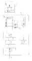
図1Aに示すように、電源アダプター1は、第1整流ユニット101と、スイッチユニット102と、トランス103と、合成ユニット104と、第1充電インターフェース105と、サンプリングユニット106と制御ユニット107とを備える。
第1整流ユニット101は、入力された交流(商用電、例えば、AC220∨)を整流して第1脈動波形の電圧、例えば、饅頭形波電圧を出力し、ここで、図2に示すように、第1整流ユニット101は、4つのダイオードからなるフルブリッジ整流回路である。
スイッチユニット102は、制御信号に基づいて第1脈動波形の電圧を変調させ、ここで、スイッチユニット102はMOS管からなり、MOS管をPWM(Pulse Width Modulation、パルス幅変調)制御して饅頭形波電圧をチョッピング変調させる。As shown in FIG. 1A, the
The
The
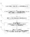
トランス103は、変調された第1脈動波形の電圧に基づいて複数の脈動波形の電圧を出力する。合成ユニット104は、複数の脈動波形の電圧を合成して第2交流を出力する。第2交流の電圧波形は、図3に示すように、第2交流の各サイクルの正の半分のピーク電圧が負の半分のトラフ電圧の絶対値より大きくてもよい。 The
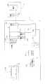
本発明の一実施形態においては、図2に示すように、電源アダプターは、フライバックスイッチユニットを利用することができる。ここで、トランス103は、一次巻線、第1の二次巻線及び第2の二次巻線を備える。
一次巻線の一端が第1整流ユニット101の第1出力端に接続され、第1整流ユニット101の第2出力端が接地され、一次巻線の他端がスイッチユニット102に接続され(例えば、このスイッチユニット102はMOS管である。ここで、一次巻線の他端はMOS管のドレインに接続され)、第1の二次巻線も接続され、第2の二次巻線はいずれも合成ユニット104に接続され、トランス103は変調された第1脈動波形の電圧に基づいて第1の二次巻線を介して第2脈動波形の電圧を出力し、変調された第1脈動波形の電圧に基づいて第2の二次巻線を介して第3脈動波形の電圧を出力する。合成ユニット104は、第2脈動波形の電圧及び第3脈動波形の電圧を合成して第2交流を出力するためのものである。In one embodiment of the present invention, as shown in FIG. 2, the power adapter can use a flyback switch unit. Here, the
One end of the primary winding is connected to the first output end of the
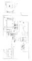
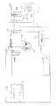
本発明の一実施形態においては、図1B及び図1Cに示すように、合成ユニット104は、電子スイッチングデバイス、例えば、MOS管からなる二つの制御可能スイッチング回路と、二つの制御可能スイッチング回路を導通または遮断されるように制御する制御モジュールとを備える。
二つの制御可能スイッチング回路は交互に導通され、交互に遮断され、例えば、制御モジュールは一方の制御可能スイッチング回路が導通され、他方の制御可能スイッチング回路が遮断されるように制御した場合、合成ユニット104が出力したのは第2交流の半分のサイクルの波形であり、制御モジュールは一方の制御可能スイッチング回路が遮断され、他方の制御可能スイッチング回路が導通されるように制御した場合、合成ユニット104が出力したのは第2交流のもう半分のサイクルの波形である。
また、図1Cに示すように、本発明の他の実施形態において、制御モジュールとして上記の制御ユニット107を利用することができる。In one embodiment of the present invention, as shown in FIGS. 1B and 1C, the combining
Two controllable switching circuits are alternately turned on and off, for example, if the control module controls such that one controllable switching circuit is turned on and the other controllable switching circuit is cut off, the combining unit The output of 104 is a waveform of a half cycle of the second alternating current, and when the control module controls so that one controllable switching circuit is cut off and the other controllable switching circuit is turned on, the
Further, as shown in FIG. 1C, in another embodiment of the present invention, the
ここで、トランス103は高周波トランスであり、その作動周波数は50KHzから2MHzであってもよい。高周波トランスは変調された第1脈動波形の電圧を二次にカップリングし、二次巻線、例えば、第1の二次巻線と第2の二次巻線とにより出力する。本発明の一実施形態においては、高周波トランスを利用し、高周波トランスが低周波トランス(低周波トランスまたは産業用周波数トランスと呼ばれ、主に商用電の周波数、例えば、50Hz又は60Hzの交流を指す)と比較して体積が小さい特徴を利用することができ、これにより電源アダプター1の小型化が実現される。 Here, the
図1Aまたは図2に示すように、第1充電インターフェース105は合成ユニット104の出力端に接続され、サンプリングユニット106は第2交流の電圧及び/又は電流をサンプリングして電圧のサンプリング値及び/又は電流のサンプリング値を得られる。
制御ユニット107はサンプリングユニット106とスイッチユニット102とにそれぞれ接続され、制御ユニット107は制御信号をスイッチユニット102に出力し、電圧サンプリング値及び/又は電流サンプリング値に基づいて制御信号のデューティ比を調節し、第2交流が端末の充電ニーズを満足するようにする。As shown in FIG. 1A or 2, the
The
図1A又は図2に示すように、端末2は、第2充電インターフェース201と電池202とを備える。第2充電インターフェース201は電池202に接続され、ここで、第2充電インターフェース201が第1充電インターフェース105に接続される場合、第2充電インターフェース201は第2交流を電池202に印加し、電池202の充電を実現する。 As illustrated in FIG. 1A or 2, the
なお、ここで、第2交流が充電ニーズを満足するとは、第2交流のピーク電圧/平均電圧とピーク電流/平均電流とが電池を充電する時の充電電圧と充電電流とを満足する必要があることを指す。つまり、制御ユニット107はサンプリングされた電源アダプターにより出力された電圧及び/又は電流、即ち第2交流の電圧及び/又は電流に基づいて、制御信号、例えば、PWM信号のデューティ比を調節し、リアルタイムに合成ユニットの出力を調整し、閉ループ調節制御を実現し、これにより第2交流は端末の充電ニーズを満足させ、電池が安全で信頼的に充電されることが保証され、具体的に、図3に示すように、PWM信号のデューティ比により電池に出力した充電電圧の波形を調整する。 Here, the fact that the second alternating current satisfies the charging needs means that the peak voltage / average voltage and the peak current / average current of the second alternating current must satisfy the charging voltage and charging current when charging the battery. It points to something. That is, the
理解されることは、PWM信号のデューティ比を調節する場合、電圧サンプリング値や、電流サンプリング値、又は電圧サンプリング値及び電流サンプリング値に基づいて調節命令を生成することができることである。 It is understood that when adjusting the duty ratio of the PWM signal, an adjustment command can be generated based on the voltage sampling value, the current sampling value, or the voltage sampling value and the current sampling value.
従って、本発明の一実施形態において、スイッチユニット102を制御することにより、フルブリッジ整流された第1脈動波形の電圧即ち饅頭形波電圧を直接的にPWMチョッピング変調を行い、高周波トランスに送り、高周波トランスにより一次から二次にカップリングされ、それから、合成ユニットの波形の合成又は交流波形の第2交流を接合出力し、電池に直接に送り込み、電池を急速充電することを実現する。ここで、第2交流の電圧振幅は、PWM信号のデューティ比に基づいて調節し、電源アダプターの出力は電池の充電ニーズを満足する。これにより、本発明の一実施形態の電源アダプターは、一次、二次の電解コンデンサをキャンセルすることができ、交流波形の電圧は直接に電池を充電することにより、電源アダプターの体積を減少させ、電源アダプターの小型化を実現し、大幅にコストダウンすることができる。 Therefore, in one embodiment of the present invention, by controlling the
ここで、本発明の一つの具体的な一例において、制御ユニット107はMCU(Micro Controller Unit、マイクロコントローラユニット)であってもよい。即ち、スイッチ駆動制御機能と、電圧電流調節制御機能とを集めたマイクロプロセッサであってもよい。 Here, in one specific example of the present invention, the
本発明の一つの実施例によると、制御ユニット107は、電圧サンプリング値及び/又は電流のサンプリング値に基づいて制御信号の周波数を調節し、即ち、スイッチユニット102に出力するPWM信号が持続的に出力してしばらく出力を停止させ、所定時間を停止した後再びPWM信号の出力を起動し、これにより電池に印加された電圧は断続的なものであり、電池の断続的に充電することを実現し、電池が連続的に充電する時に発熱のひどさにより発生したセキュリティリスクを避けられ、電池充電の信頼性と安全性とを向上させる。 According to one embodiment of the present invention, the
リチウム電池は、低温条件で、リチウム電池自体のイオンと電子導電能力の低下により、充電する過程に分極程度の強化を容易にでき、持続的に充電する方式はこのような分極をより著しくなり、同時にリチウム析出が形成する可能性を増加し、これにより電池の安全性能に影響を及ぼす。また、持続的な充電方法は充電により熱が蓄積し続けることになり、電池内部の温度が徐々に上昇し、温度が一定的な限度値を超えた場合、電池性能の発揮が制限され、同時にセキュリティリスクも増える。 Lithium battery can easily enhance the degree of polarization in the charging process due to the decrease in ion and electronic conductivity of lithium battery itself at low temperature conditions, and the continuous charging method makes such polarization more remarkable, At the same time, the possibility of lithium deposition is increased, thereby affecting the safety performance of the battery. In addition, the continuous charging method will continue to accumulate heat by charging, and if the temperature inside the battery gradually rises and the temperature exceeds a certain limit value, the performance of the battery will be limited, and at the same time Security risks also increase.
本発明の一実施形態において、制御信号の周波数を調節することにより、電源アダプターが間歇的に出力し、即ち、電池が充電する過程に電池静置過程を導入し、持続的に充電する過程に分極によるリチウム析出が緩まり、且つ生成された熱の持続的な蓄積の影響を弱め、温度低下の効果を達成し、電池充電の信頼性と安全性を保証する。 In one embodiment of the present invention, by adjusting the frequency of the control signal, the power adapter outputs intermittently, i.e., the battery stationary process is introduced into the process of charging the battery, and the process of charging continuously. Lithium deposition due to polarization is relaxed and the effect of sustained accumulation of generated heat is weakened, the effect of lowering temperature is achieved, and the reliability and safety of battery charging are ensured.
ここで、スイッチユニット102に出力された制御信号は、図4に示すように、まずしばらく持続的にPWM信号を出力し、その後出力をしばらく停止させ、それからまたしばらく持続的にPWM信号を出力し、スイッチユニット102に出力された制御信号が隔離され、且つ周波数を調整することができる。 Here, as shown in FIG. 4, the control signal output to the
図2に示すように、制御ユニット107は、第1充電インターフェース105に接続される。制御ユニット107は、第1充電インターフェース105を介して端末2と通信を行って端末2の状態情報を取得する。このように、制御ユニット107は端末の状態情報と、電圧のサンプリング値及び/又は電流サンプリング値により制御信号例えば、PWM信号のデューティ比を調節する。 As shown in FIG. 2, the
ここで、端末の状態情報は、電池の電気量と、電池の温度と、端末の電池の電圧/電流と、端末のインターフェース情報と、端末の通路抵抗の情報等とを含む。 Here, the state information of the terminal includes the amount of electricity of the battery, the temperature of the battery, the voltage / current of the battery of the terminal, the interface information of the terminal, the information on the passage resistance of the terminal, and the like.
具体的には、第1充電インターフェース105は、電源線とデータ線とを備え、電源線は電池を充電するためのものであり、データ線は端末と通信を行うためのものである。第2充電インターフェース201が第1充電インターフェース105に接続される場合、電源アダプター1と端末2の間に互いに通信問い合わせ命令を送信することができる。更に、対応的な応答命令を受信した後、電源アダプター1と端末2との間に通信接続を確立し、制御ユニット107は端末2の状態情報を得られることにより、充電モードと充電パラメータ(例えば充電電流、充電電圧)について端末2とネゴシエーションし、充電過程を更に制御する。 Specifically, the
ここで、電源アダプター及び/又は端末がサポートする充電モードは、普通充電モードと急速充電モードとを含む。急速充電モードは、普通充電モードより充電速度が大きい(例えば、急速充電モードは、普通充電モードより充電電流が大きい)。一般的に、普通充電モードは、定格出力電圧が5∨であり、定格出力電流が2.5A以下である充電モードであると理解される。また、普通充電モードで、電源アダプターの出力ポートデータ線におけるD+とD−とは短絡することができる。しかし本発明の実施形態における急速充電モードは異なり、本発明の実施形態の急速充電モードで電源アダプターはデータ線におけるD+とD−とが端末と通信を行ってデータ交換を実現する。即ち、電源アダプターと端末との間に互いに急速充電命令を送信することができ、電源アダプターは、端末に急速充電問い合わせ命令を送信し、端末の急速充電応答命令を受信した後、端末の応答命令に基づいて、電源アダプターは端末の状態情報を得られ、急速充電モードを起動し、急速充電モードで充電電流は2.5Aより大きく、例えば、4.5A、或いはより大きいであってもよい。しかし、本発明の実施形態は普通充電モードを具体的に限定せず、電源アダプターは2つの充電モードをサポートすればよく、その中の一方の充電モードの充電速度(又は電流)は他方の充電モードの充電速度より大きくすると、充電速度が遅い方の充電モードは、普通充電モードと理解される。充電電力に対して、急速充電モードで充電電力は15W以上であってもよい。 Here, the charging mode supported by the power adapter and / or the terminal includes a normal charging mode and a quick charging mode. The quick charge mode has a higher charge rate than the normal charge mode (for example, the quick charge mode has a higher charge current than the normal charge mode). In general, the normal charging mode is understood to be a charging mode in which the rated output voltage is 5 liters and the rated output current is 2.5 A or less. In the normal charging mode, D + and D- in the output port data line of the power adapter can be short-circuited. However, the quick charge mode in the embodiment of the present invention is different, and in the quick charge mode of the embodiment of the present invention, the power adapter realizes data exchange by communicating D + and D− on the data line with the terminal. That is, a quick charge command can be transmitted between the power adapter and the terminal, and the power adapter transmits a quick charge inquiry command to the terminal and receives the quick charge response command of the terminal, and then the response command of the terminal , The power adapter can obtain the terminal status information and activate the quick charge mode, where the charging current may be greater than 2.5A, for example, 4.5A or greater. However, the embodiment of the present invention does not specifically limit the normal charging mode, and the power adapter only needs to support two charging modes, and the charging speed (or current) of one charging mode among them is the charging of the other charging mode. When larger than the charging speed of the mode, the charging mode with the slower charging speed is understood as the normal charging mode. The charging power may be 15 W or more in the quick charging mode with respect to the charging power.
即ち、制御ユニット107は、第1充電インターフェース105を介して端末2と通信を行って充電モードを決定し、ここで、充電モードは急速充電モードと普通充電モードとを含む。 That is, the
具体的には、前記電源アダプターは、ユニバーサル・シリアル・バス(USB:Universal Serial Bus)インターフェースにより端末に接続され、このUSBインターフェースは普通のUSBインターフェース出会ってもよいし、Micro USBインターフェースであってもよい。USBインターフェースにおけるデータ線、即ち第1充電インターフェースにおけるデータ線は電源アダプターと端末とが双方向通信を行い、このデータ線はUSBインターフェースにおけるD+線及び/又はD−線であってもよく、双方向通信とは電源アダプターと端末とが両方で情報の交互を行うことである。 Specifically, the power adapter is connected to a terminal by a universal serial bus (USB) interface, and this USB interface may meet a normal USB interface or a micro USB interface. Good. The data line in the USB interface, that is, the data line in the first charging interface, performs bidirectional communication between the power adapter and the terminal, and this data line may be a D + line and / or a D− line in the USB interface. Communication means that information is exchanged between the power adapter and the terminal.
ここで、電源アダプターは、USBインターフェースにおけるデータ線を介して、端末と双方向通信を行い、急速充電モードで端末を充電すると決定する。 Here, the power adapter determines to charge the terminal in the quick charge mode by performing bidirectional communication with the terminal via the data line in the USB interface.
なお、電源アダプターは端末にネゴシエーションして急速充電モードで端末を充電するか否かの過程に、電源アダプターは端末に接続された状態を保つだけで、充電しないことができるが、普通充電モードで端末を充電することもできるし、小さい電流で端末を充電することもでき、本発明の実施形態はこれを具体的に限定しない。 In the process of whether or not the power adapter negotiates with the terminal and charges the terminal in the quick charge mode, the power adapter can only be kept connected to the terminal and not be charged. The terminal can be charged or the terminal can be charged with a small current, and the embodiment of the present invention does not specifically limit this.
電源アダプターは、充電電流を急速充電モードに対応する充電電流に調整し、端末を充電する。電源アダプターは急速充電モードで端末を充電することが決定された後、充電電流を急速充電モードに対応する充電電流に直接的に調整することができ、端末に急速充電モードの充電電流をネゴシエーションすることもでき、例えば、端末における電池の現在の電気量により急速充電モードに対応する充電電流を決定する。 The power adapter adjusts the charging current to a charging current corresponding to the quick charging mode, and charges the terminal. After the power adapter is determined to charge the device in the quick charge mode, the charging current can be adjusted directly to the charge current corresponding to the quick charge mode, and the device will negotiate the charge current in the quick charge mode For example, the charging current corresponding to the quick charging mode is determined by the current amount of electricity of the battery in the terminal.
本発明の実施形態において、電源アダプターは盲目的に電流を出力して急速充電するものではなく、端末に双方向通信を行って、急速充電モードを利用することができるか否かについてネゴシエーションし、従来技術と比較して、急速充電過程の安全性を向上させる。 In an embodiment of the present invention, the power adapter does not blindly output current and quickly charge, but performs bidirectional communication with the terminal to negotiate whether or not the quick charge mode can be used, Compared with the prior art, improve the safety of quick charging process.
好ましくは、一つの実施例として、制御ユニット107は、第1充電インターフェースにおけるデータ線を介して端末と双方向通信を行い、急速充電モードで端末を充電することが決定された場合、制御ユニットは端末に第1命令を送信すると、第1命令は端末が急速充電モードを起動するか否かを問い合わせることに用いる。制御ユニットは端末から第1命令の返信命令を受信し、第1命令の返信命令は端末が急速充電モードの起動を同意するように端末を指示するためのものである。 Preferably, as one embodiment, the
好ましくは、一つの実施例として、制御ユニットが端末に第1命令を送信する前に、電源アダプターと端末との間に普通充電モードで充電し、制御ユニットにより普通充電モードの充電時間は予め設定された閾値より大きいと決定された後、端末に第1命令を送信する。 Preferably, as one embodiment, before the control unit sends the first command to the terminal, charging is performed between the power adapter and the terminal in the normal charging mode, and the charging time of the normal charging mode is preset by the control unit. The first command is transmitted to the terminal after it is determined that the threshold is greater than the threshold value.
なお、電源アダプターにより普通充電モードの充電時間が予め設定された閾値より大きいと決定された後、電源アダプターは自身が電源アダプターであることが既に端末に認識され、急速充電問い合わせ通信を起動することができると考えられると理解されるべきである。 In addition, after it is determined by the power adapter that the charging time in the normal charging mode is greater than a preset threshold, the power adapter is already recognized by the terminal as being a power adapter and the quick charge inquiry communication is started. It should be understood that it is considered possible.
好ましくは、一つの実施例として、電源アダプターは予め設定された電流閾値以上の充電電流で予め設定された時間充電した後、端末に前記第1命令を送信する。 Preferably, as one embodiment, the power adapter transmits the first command to the terminal after charging for a preset time with a charge current equal to or greater than a preset current threshold.
好ましくは、一つの実施例として、制御ユニットは、スイッチユニットを制御することにより電源アダプターが充電電流を急速充電モードに対応する充電電流に調整するように電源アダプターを制御し、電源アダプターは急速充電モードに対応する充電電流で端末を充電する前に、制御ユニットが第1充電インターフェースにおけるデータ線を介して端末と双方向通信を行い、急速充電モードに対応する充電電圧を決定し、電源アダプターが充電電圧を急速充電モードに対応する充電電圧に調整するように制御する。 Preferably, as one embodiment, the control unit controls the power adapter so that the power adapter adjusts the charging current to the charging current corresponding to the quick charging mode by controlling the switch unit, and the power adapter is quickly charged. Before charging the terminal with the charging current corresponding to the mode, the control unit performs two-way communication with the terminal via the data line in the first charging interface, determines the charging voltage corresponding to the quick charging mode, and the power adapter Control is performed so that the charging voltage is adjusted to a charging voltage corresponding to the rapid charging mode.
好ましくは、一つの実施例として、制御ユニットが第1充電インターフェースにおけるデータ線を介して端末と双方向通信を行い、急速充電モードに対応する充電電圧を決定された場合、制御ユニットは端末に第2命令を送信し、第2命令は、電源アダプターの現在出力電圧が急速充電モードの充電電圧として適切であるか否かを問い合わせるためのものである。制御ユニットは端末により送信された第2命令の返信命令を受信し、第2命令の返信命令は電源アダプターの現在出力電圧が適切や、やや高いか又はやや低いかを指示するためのものである。制御ユニットは第2命令の返信命令に基づいて、急速充電モードの充電電圧を決定する。 Preferably, as one embodiment, when the control unit performs bidirectional communication with the terminal via the data line in the first charging interface and the charging voltage corresponding to the quick charging mode is determined, the control unit Two commands are transmitted, and the second command is for inquiring whether or not the current output voltage of the power adapter is appropriate as the charging voltage in the quick charge mode. The control unit receives the reply command of the second command transmitted by the terminal, and the reply command of the second command is for indicating whether the current output voltage of the power adapter is appropriate, slightly higher or slightly lower . The control unit determines the charging voltage in the quick charging mode based on the reply command of the second command.
好ましくは、一つの実施例として、制御ユニットは、充電電流を急速充電モードに対応する充電電流に調整するように電源アダプターを制御する前に、第1充電インターフェースにおけるデータ線を介して端末と双方向通信を行い、急速充電モードに対応する充電電流を決定する。 Preferably, as one embodiment, the control unit is connected to the terminal via the data line in the first charging interface before controlling the power adapter to adjust the charging current to the charging current corresponding to the quick charging mode. To determine the charge current corresponding to the quick charge mode.
好ましくは、一つの実施例として、制御ユニットが第1充電インターフェースにおけるデータ線を介して端末と双方向通信を行い、急速充電モードに対応する充電電流を決定する場合、制御ユニットは端末に第3命令を送信し、第3命令は端末の現在サポートする最大充電電流を問い合わせるためのものである。制御ユニットは端末により送信された第3命令の返信命令を受信し、第3命令の返信命令は端末の現在サポートする最大充電電流を指示する。制御ユニットは第3命令の返信命令に基づいて、急速充電モードの充電電流を決定する。 Preferably, in one embodiment, when the control unit performs two-way communication with the terminal via the data line in the first charging interface and determines the charging current corresponding to the quick charging mode, the control unit The third command is for inquiring the maximum charging current that the terminal currently supports. The control unit receives a third command reply command sent by the terminal, and the third command reply command indicates the maximum charging current currently supported by the terminal. The control unit determines the charging current in the quick charge mode based on the return command of the third command.
電源アダプターは上記最大充電電流を直接的に急速充電モードの充電電流と決定するか、又は充電電流をこの最大充電電流のある電流値より小さくすることができる。 The power adapter can directly determine the maximum charging current as the charging current in the quick charging mode, or make the charging current smaller than a certain current value of the maximum charging current.
好ましくは、一つの実施例として、電源アダプターが急速充電モードで端末を充電する過程に、制御ユニットが第1充電インターフェースにおけるデータ線を介して端末と双方向通信を行い、スイッチユニットを制御することにより電源アダプターが電池に出力した充電電流を絶え間なく調整する。 Preferably, in one embodiment, the control unit performs bidirectional communication with the terminal via the data line in the first charging interface to control the switch unit while the power adapter charges the terminal in the quick charge mode. The power adapter adjusts the charging current output to the battery continuously.
電源アダプターは端末の現在状態情報をずっと問い合わせることができ、例えば、端末の電池電圧や、電池電気量等を問い合わせして、電源アダプターが電池に出力した充電電流を調整する。 The power adapter can always inquire about the current state information of the terminal. For example, it inquires about the battery voltage of the terminal, the amount of electricity in the battery, etc., and adjusts the charging current output from the power adapter to the battery.
好ましくは、一つの実施例として、制御ユニットが第1充電インターフェースにおけるデータ線を介して端末と双方向通信を行い、電源アダプターが電池に出力した充電電流を絶え間なく調整するようにスイッチユニットを制御する場合、制御ユニットは端末に第4命令を送信し、第4命令は端末内の電池の現在電圧を問い合わせるためのものである。制御ユニットは端末により送信された第4命令の返信命令を受信し、第4命令の返信命令は端末内の電池の現在電圧を指示するためのものである。制御ユニットは電池の現在電圧に基づいて、スイッチユニットを制御することにより電源アダプターが電池に出力した充電電流を調整する。 Preferably, in one embodiment, the control unit performs two-way communication with the terminal via the data line in the first charging interface, and controls the switch unit so as to continuously adjust the charging current output from the power adapter to the battery. If so, the control unit sends a fourth command to the terminal, which is for querying the current voltage of the battery in the terminal. The control unit receives the fourth command reply command transmitted by the terminal, and the fourth command reply command is for indicating the current voltage of the battery in the terminal. The control unit adjusts the charging current output from the power adapter to the battery by controlling the switch unit based on the current voltage of the battery.
好ましくは、一つの実施例として、制御ユニットは電池の現在電圧、及び予め設定された電池電圧値と充電電流値の対応関係に基づいて、スイッチユニットを制御することにより電源アダプターが電池に出力した充電電流を電池の現在電圧に対応する充電電流値に調整する。 Preferably, as one embodiment, the control unit controls the switch unit based on the current voltage of the battery and the correspondence between the preset battery voltage value and the charging current value, and the power adapter outputs to the battery. The charging current is adjusted to a charging current value corresponding to the current voltage of the battery.
具体的には、電源アダプターは、電池電圧値と充電電流値の対応関係を予め記憶し、電源アダプターは第1充電インターフェースにおけるデータ線を介して端末と双方向通信を行い、端末側から端末内に記憶された電池電圧値と充電電流値の対応関係を取得する。 Specifically, the power adapter stores the correspondence between the battery voltage value and the charging current value in advance, and the power adapter performs two-way communication with the terminal via the data line in the first charging interface. The correspondence relationship between the battery voltage value stored in the battery and the charging current value is acquired.
好ましくは、一つの実施例として、電源アダプターが急速充電モードで端末を充電する過程に、制御ユニットは、更に、第1充電インターフェースにおけるデータ線を介して端末と双方向通信を行い、第1充電インターフェースと第2充電インターフェースとの間に接触不良が発生したか否かを決定し、ここで、第1充電インターフェースと第2充電インターフェースとの間に接触不良が発生されたと決定される場合、制御ユニットは、急速充電モードを退出するように電源アダプターを制御する。 Preferably, in one embodiment, in the process of the power adapter charging the terminal in the quick charge mode, the control unit further performs bi-directional communication with the terminal via the data line in the first charging interface, Determining whether a contact failure has occurred between the interface and the second charging interface, wherein if it is determined that a contact failure has occurred between the first charging interface and the second charging interface, the control The unit controls the power adapter to exit the fast charge mode.
好ましくは、一つの実施例として、第1充電インターフェースと第2充電インターフェースとの間に接触不良が発生されたと決定される前に、制御ユニットは、更に、端末により端末の通路抵抗を指示するための情報を受信する。ここで、制御ユニットは、端末に第4命令を送信し、第4命令は端末内の電池の電圧を問い合わせるためのものである。制御ユニットは端末により送信された第4命令の返信命令を受信し、第4命令の返信命令は端末内の電池を指示するための電圧である。制御ユニットは電源アダプターの出力電圧と電池の電圧とに基づいて、電源アダプターから電池までの通路抵抗を決定する。制御ユニットは、電源アダプターから電池までの通路抵抗と、端末までの通路抵抗と、電源アダプターと端末との間の充電線線路の通路抵抗とに基づいて、第1充電インターフェースと第2充電インターフェースとの間に接触不良が発生したか否かを決定する。 Preferably, as one example, before it is determined that a contact failure has occurred between the first charging interface and the second charging interface, the control unit further indicates the passage resistance of the terminal by the terminal. Receive the information. Here, the control unit transmits a fourth command to the terminal, and the fourth command is for inquiring the voltage of the battery in the terminal. The control unit receives a fourth command reply command transmitted by the terminal, and the fourth command reply command is a voltage for indicating a battery in the terminal. The control unit determines the passage resistance from the power adapter to the battery based on the output voltage of the power adapter and the voltage of the battery. The control unit includes a first charging interface and a second charging interface based on a path resistance from the power adapter to the battery, a path resistance to the terminal, and a path resistance of the charging line between the power adapter and the terminal. It is determined whether a contact failure has occurred during the period.
端末はその通路抵抗を予め記録することができ、例えば、同一型番の端末は構造が一致することで、工場設定した場合、この端末の通路抵抗を同一値に設定する。同様で、電源アダプターは充電線路の通路抵抗を予め設定することができる。電源アダプターが端末の電池両端の電圧を取得した場合、電源アダプターが電池両端の圧力降下及び通路の電流に基づいて、通路全体の通路抵抗を決定することができ、当通路全体の通路抵抗>端末の通路抵抗+充電線路の通路抵抗、又は通路全体の通路抵抗−(端末の通路抵抗+充電線路の通路抵抗)>抵抗閾値である場合、第1充電インターフェースと第2充電インターフェースとの間に接触不良が発生したと思われる。 The terminal can record the passage resistance in advance. For example, when the terminals of the same model number have the same structure, the passage resistance of the terminal is set to the same value when factory setting is performed. Similarly, the power adapter can preset the passage resistance of the charging line. When the power adapter acquires the voltage across the battery of the terminal, the power adapter can determine the path resistance of the entire path based on the pressure drop across the battery and the current in the path, and the path resistance of the entire path> terminal Passage resistance + passage resistance of the charging line, or passage resistance of the entire passage− (passage resistance of the terminal + passage resistance of the charging line)> resistance threshold, contact between the first charging interface and the second charging interface It seems that a defect occurred.
好ましくは、一つの実施例として、電源アダプターが急速充電モードを退出する前に、制御ユニットは端末に第5命令を送信し、第5命令は第1充電インターフェースと第2充電インターフェースとの間の接触不良を指示するものである。 Preferably, as one embodiment, before the power adapter exits the quick charge mode, the control unit sends a fifth command to the terminal, the fifth command is between the first charge interface and the second charge interface. It indicates a contact failure.
電源アダプターは第5命令を送信した後、急速充電モードを退出する又はリセットする。 After the power adapter sends the fifth command, it exits or resets the quick charge mode.
以上、電源アダプターの角度から本発明の一実施形態における急速充電過程を詳しく説明し、以下に、端末の角度から本発明の一実施形態における急速充電過程を説明する。 The quick charging process in the embodiment of the present invention will be described in detail from the angle of the power adapter, and the rapid charging process in the embodiment of the present invention will be described below from the angle of the terminal.
端末側において説明される電源アダプターと端末の交互及関連特性、機能等は、電源アダプター側における説明に対応しているため、簡潔に、重複する説明は適当に省略する。 Since the interrelated characteristics and functions of the power adapter and the terminal explained on the terminal side correspond to the explanation on the power adapter side, a concise and duplicative explanation is appropriately omitted.
本発明の一つの実施例によると、図12に示すように、端末2は、充電制御スイッチ203とコントローラー204とを更に備える。充電制御スイッチ203は、例えば、電子スイッチングデバイスからなるスイッチ回路は、第2充電インターフェース201と電池202との間に接続され、充電制御スイッチ203はコントローラー204の制御で電池の充電過程を閉じる/開くためのものであり、このように端末側から電池の充電過程を制御することができ、電池の充電の安全性と信頼性を保証することができる。 According to one embodiment of the present invention, the
また、図13に示すように、端末2は、通信ユニット205を更に備える。通信ユニット205は、第2充電インターフェース201と第1充電インターフェース105とにより、コントローラー204と制御ユニット107の間の双方向通信を作成する。即ち、端末と電源アダプターとはUSBインターフェースにおけるデータ線により双方向通信を行うことができ、前記端末は普通充電モードと急速充電モードとをサポートし、ここで急速充電モードでの充電電流が普通充電モードでの充電電流より大きく、コントローラーは通信ユニットと制御ユニットとが双方向通信を行って電源アダプターが急速充電モードを利用して端末を充電すると決定し、制御ユニットは電源アダプターが急速充電モードに対応する充電電流に従って出力し、端末内の電池を充電するように制御する。 As shown in FIG. 13, the
本発明の実施例において、電源アダプターは盲目的に電流を出力して急速充電するものではなく、端末に双方向通信を行って、急速充電モードを利用することができるか否かについてネゴシエーションし、従来技術と比較して、急速充電過程の安全性を向上させる。 In an embodiment of the present invention, the power adapter does not blindly output current and quickly charge, but performs bidirectional communication with the terminal to negotiate whether or not the quick charge mode can be used, Compared with the prior art, improve the safety of quick charging process.
好ましくは、一つの実施例として、コントローラーは通信ユニットにより制御ユニットにより送信された第1命令を受信し、第1命令は端末が急速充電モードを起動するか否かを問い合わせるためのものである。コントローラーは通信ユニットにより制御ユニットに第1命令の返信命令を送信し、第1命令の返信命令は端末が急速充電モードの起動を同意するように端末を指示するためのものである。 Preferably, in one embodiment, the controller receives a first command sent by the control unit by the communication unit, and the first command is for inquiring whether the terminal activates the quick charge mode. The controller transmits a reply command of the first command to the control unit by the communication unit, and the reply command of the first command is for instructing the terminal so that the terminal agrees to start the quick charge mode.
好ましくは、一つの実施例として、コントローラーは通信ユニットにより制御ユニットにより送信された第1命令を受信する前に、電源アダプターは普通充電モードで端末内の電池を充電し、制御ユニットにより普通充電モードの充電時間が予め設定された閾値より大きいと決定された後、制御ユニットは端末内の通信ユニットに第1命令を送信し、コントローラーは通信ユニットにより制御ユニットにより送信された第1命令を受信する。 Preferably, as one embodiment, before the controller receives the first command sent by the control unit by the communication unit, the power adapter charges the battery in the terminal in the normal charge mode, and the control unit uses the normal charge mode. After the charging time is determined to be greater than a preset threshold, the control unit sends a first command to the communication unit in the terminal, and the controller receives the first command sent by the control unit by the communication unit .
好ましくは、一つの実施例として、電源アダプターは、急速充電モードに対応する充電電流に従って出力し、端末内の電池を充電する前に、コントローラーは通信ユニットにより制御ユニットと双方向通信を行い、電源アダプターが急速充電モードに対応する充電電圧を決定するようにする。 Preferably, as one embodiment, the power adapter outputs according to the charging current corresponding to the quick charge mode, and before charging the battery in the terminal, the controller performs two-way communication with the control unit by the communication unit, Let the adapter determine the charging voltage corresponding to the fast charging mode.
好ましくは、一つの実施例として、コントローラーは制御ユニットにより送信された第2命令を受信し、第2命令は電源アダプターの現在出力電圧が急速充電モードの充電電圧として適切であるか否かを問い合わせるためのものである。コントローラーは制御ユニットに第2命令の返信命令を送信し、第2命令の返信命令は電源アダプターの現在出力電圧が適切や、やや高いか又はやや低いかを指示するためのものである。 Preferably, in one embodiment, the controller receives a second command sent by the control unit, and the second command queries whether the current output voltage of the power adapter is appropriate as the charge voltage for the fast charge mode. Is for. The controller transmits a reply command of the second command to the control unit, and the reply command of the second command is for instructing whether the current output voltage of the power adapter is appropriate, slightly higher or slightly lower.
好ましくは、一つの実施例として、電源アダプターにより急速充電モードに対応する充電電流を決定するように、コントローラーは制御ユニットと双方向通信する。 Preferably, in one embodiment, the controller is in two-way communication with the control unit such that the power adapter determines the charging current corresponding to the fast charge mode.
ここで、コントローラーは、制御ユニットにより送信された第3命令を受信し、第3命令は、端末の現在サポートする最大充電電流を問い合わせるためのものである。コントローラーは制御ユニットに第3命令の返信命令を送信し、第3命令の返信命令は端末の現在サポートする最大充電電流を指示するためのものであり、電源アダプターが最大充電電流に基づいて急速充電モードに対応する充電電流を決定する。 Here, the controller receives the third command transmitted by the control unit, and the third command is for inquiring about the maximum charging current currently supported by the terminal. The controller sends a third command reply command to the control unit, the third command reply command is used to indicate the maximum charge current currently supported by the terminal, and the power adapter quickly charges based on the maximum charge current. The charging current corresponding to the mode is determined.
好ましくは、一つの実施例として、電源アダプターが急速充電モードで端末を充電する過程に、コントローラーは制御ユニットと双方向通信を行うことにより、電源アダプターが電源アダプターが電池に出力した充電電流を絶え間なく調整させる。 Preferably, as one embodiment, during the process in which the power adapter charges the terminal in the quick charge mode, the controller performs two-way communication with the control unit, so that the power adapter continuously outputs the charging current output from the power adapter to the battery. Make them adjust.
ここで、コントローラーは、制御ユニットにより送信された第4命令を受信し、第4命令は端末内の電池の現在電圧を問い合わせるためのものである。コントローラーは制御ユニットに第4命令の返信命令を送信し、第4命令の返信命令は端末内の電池の現在電圧を指示するためのものであり、電源アダプターが電池の現在電圧に基づいて、電源アダプターが電池に出力した充電電流を絶え間なく調整させる。 Here, the controller receives the fourth command transmitted by the control unit, and the fourth command is for inquiring the current voltage of the battery in the terminal. The controller sends a fourth command reply command to the control unit, and the fourth command reply command is for indicating the current voltage of the battery in the terminal. The adapter continuously adjusts the charging current output to the battery.
好ましくは、一つの実施例として、電源アダプターが急速充電モードで端末を充電する過程において、コントローラーは通信ユニットにより制御ユニットと双方向通信を行い、電源アダプターが第1充電インターフェースと第2充電インターフェースとの間に接触不良が発生したか否かを決定する。 Preferably, in one embodiment, in the process in which the power adapter charges the terminal in the quick charge mode, the controller performs two-way communication with the control unit through the communication unit, and the power adapter includes the first charging interface and the second charging interface. It is determined whether a contact failure has occurred during the period.
ここで、コントローラーは制御ユニットにより送信された第4命令を受信し、第4命令は端末内の電池の現在電圧を問い合わせるためのものである。コントローラーは制御ユニットに第4命令の返信命令を送信し、第4命令の返信命令は端末内の電池の現在電圧を指示するためのものであり、制御ユニットは電源アダプターの出力電圧と電池の現在電圧と基づいて、第1充電インターフェースと第2充電インターフェースとの間に接触不良が発生したか否かを決定する。 Here, the controller receives the fourth command transmitted by the control unit, and the fourth command is for inquiring the current voltage of the battery in the terminal. The controller sends a fourth command reply command to the control unit, and the fourth command reply command is for indicating the current voltage of the battery in the terminal. Based on the voltage, it is determined whether a contact failure has occurred between the first charging interface and the second charging interface.
好ましくは、一つの実施例として、コントローラーは制御ユニットにより送信された第5命令を受信し、第5命令は第1充電インターフェースと第2充電インターフェースとの間に接触不良を指示するためのものである。 Preferably, in one embodiment, the controller receives a fifth command sent by the control unit, the fifth command is for indicating a contact failure between the first charging interface and the second charging interface. is there.
急速充電モードを起動して使用するために、電源アダプターは急速充電通信の流れを端末と行うことができ、一回又は数回のハンドシェークにより、電池の急速充電を実現する。以下に、図5を参照しながら、本発明の一実施形態における急速充電通信の流れ、及び急速充電過程に含まれた各段階を詳しく説明する。図5に示された通信ステップ又は操作は、ただ例示的なものであり、本発明の一実施形態は他の操作、又は図5に示された様々な操作の変形を更に実行することができると理解されるべきである。
また、図5における各段階は図5に示されたような順序と異なる順序で実行することもでき、且つ図5における全部操作を実行するものではない。なお、ここで、図5に示めされた曲線は充電電流のピーク値又は平均値の変化傾向であり、実際的な充電電流曲線ではない。In order to activate and use the quick charge mode, the power adapter can perform a quick charge communication flow with the terminal, and realize quick charge of the battery by one or several handshakes. Hereinafter, with reference to FIG. 5, the flow of the quick charge communication and the steps included in the quick charge process according to an embodiment of the present invention will be described in detail. The communication steps or operations shown in FIG. 5 are merely exemplary, and one embodiment of the present invention may further perform other operations or variations of the various operations shown in FIG. Should be understood.
5 can be executed in an order different from the order shown in FIG. 5 and not all the operations in FIG. 5 are executed. Here, the curve shown in FIG. 5 is a change tendency of the peak value or average value of the charging current, and is not an actual charging current curve.
図5に示すように、急速充電過程は以下のような5つの段階を含む。 As shown in FIG. 5, the quick charging process includes the following five steps.
段階1
端末は電源提供装置に接続された後、端末はデータ線D+,D−により電源提供装置のタイプを検出することができ、検出された電源提供装置が電源アダプターである場合、端末により吸収された電流は予め設定された電流閾値I2(例えば、1Aである)より大きくてもよい。電源アダプターは予め設定された時間(例えば、連続的なT1時間であってもよい)内の電源アダプターにより出力された電流はI2以上である場合、電源アダプターは端末が電源提供装置のタイプに対する認識が完成したと思われ、電源アダプターはアダプターと端末との間のハンドシェイク通信を起動し、電源アダプターは命令1(上記第1命令に対応する)を送信して端末が急速充電モード(又はフラッシュ充電)を起動したか否かを問い合わせる。
After the terminal is connected to the power supply device, the terminal can detect the type of the power supply device by the data lines D + and D−, and if the detected power supply device is a power adapter, the terminal is absorbed by the terminal. The current may be greater than a preset current threshold I2 (eg, 1A). If the power adapter outputs a current that is greater than or equal to I2 within a preset time (for example, it may be a continuous T1 time), the power adapter recognizes the type of power supply device by the terminal The power adapter initiates handshake communication between the adapter and the terminal, the power adapter sends command 1 (corresponding to the first command above) and the terminal is in fast charge mode (or flash Queries whether or not (Charge) is activated.
電源アダプターが端末の返信命令を受信して端末が急速充電モードの起動を同意しない場合、電源アダプターの出力電流を再度検出し、電源アダプターの出力電流は予め設定された連続時間内(例えば、連続的なT1時間)で依然としてI2以上である場合、再度リクエストして端末が急速充電モードを起動するか否かを問い合わせし、段階1の上記ステップを繰り返し、端末が急速充電モードの起動を同意する、又は電源アダプターの出力電流はI2以上であると条件を満足するまで。 If the power adapter receives the terminal's reply command and the terminal does not agree to start the quick charge mode, the power adapter's output current is detected again, and the power adapter's output current is within a preset continuous time (for example, continuous If it is still I2 or more at a typical T1 time), request again to inquire whether or not the terminal activates the quick charge mode, repeat the above steps of
端末が急速充電モードの起動を同意した後、急速充電過程は開始し、急速充電通信の流れは第2段階に移行する。 After the terminal agrees to start the quick charge mode, the quick charge process starts and the flow of the quick charge communication proceeds to the second stage.
段階2
電源アダプターにより出力された饅頭形波電圧は、複数の電圧レベルを含み、電源アダプターは端末に命令2(上記第2命令に対応する)を送信して端末に電源アダプターの出力電圧が電池の現在電圧(又は適切であるか否か、即ち、急速充電モードでの充電電圧として適切か否か)にマッチングしているか否かを問い合わせし、即ち充電ニーズを満足するか否かを問い合わせる。
The truncated wave voltage output by the power adapter includes multiple voltage levels, the power adapter sends
端末は電源アダプターの出力電圧がやや高い又はやや低い又はマッチングしていると応答し、電源アダプターは端末のアダプターの出力電圧がやや高い又はやや低いとフィードバックを受信した場合、制御ユニットはPWM信号のデューティ比を調節することにより電源アダプターの出力電圧を一つの電圧レベルだけ調整し、端末に命令2を再度送信し、端末に電源アダプターの出力電圧がマッチングしているか否かを改めて問い合わせる。 If the terminal responds that the output voltage of the power adapter is slightly higher or slightly lower or matching, and the power adapter receives feedback that the output voltage of the terminal adapter is slightly higher or slightly lower, the control unit By adjusting the duty ratio, the output voltage of the power adapter is adjusted by one voltage level,
段階2を繰り返して、以上のステップに基づいて端末が電源アダプターにその出力電圧がマッチングしている電圧レベルにあると返信した場合、第3段階に移行する。 If
段階3
電源アダプターは、端末により返信された電源アダプターの出力電圧がマッチングしているとのフィードバックを受信した後、電源アダプターは端末に命令3(上記第3命令に対応する)を送信し、端末に現在サポートしている最大充電電流を問い合わせ、端末は電源アダプターにその現在サポートしている最大充電電流値を返信し、第4段階に移行する。Stage 3
After the power adapter receives feedback that the output voltage of the power adapter returned by the terminal matches, the power adapter sends command 3 (corresponding to the third command above) to the terminal and The terminal inquires about the maximum charging current supported, the terminal returns the currently supported maximum charging current value to the power adapter, and proceeds to the fourth stage.
段階4
電源アダプターは、端末により返信された現在サポートしている最大充電電流値のフィードバックを受信した後、電源アダプターはその出力電流基準値を設けることができる。制御ユニット107はこの電流基準値に基づいてPWM信号のデューティ比を調節し、電源アダプターの出力電流が端末充電電流ニーズを満足するようにさせ、即ち、定電流段階に移行する。ここで、定電流段階とは、電源アダプターの出力電流ピーク値又は電流平均値が基本的に変わらないままで(つまり出力電流ピーク値又は電流平均値の変化幅が小さい。例えば、出力電流ピーク値又は平均値の5%範囲内で変化する)、即ち、第2交流のピーク電流は各サイクルで一定に保持する。
After the power adapter receives the feedback of the currently supported maximum charging current value returned by the terminal, the power adapter can set its output current reference value. The
段階5
電流が一定的に変化する段階に移行した場合、電源アダプターは一定的な時間置きに命令4(上記第4命令に対応する)を送信し、端末に電池の現在電圧を問い合わせし、端末は電源アダプターに端末電池の現在電圧をフィードバックすることができ、電源アダプターは端末の端末電池に関する現在電圧のフィードバックにより、USB接触即ち第1充電インターフェースと第2充電インターフェースとの間の接触は良好であるか、及び端末の現在の充電電流値を低下させる必要はあるか否かを判断する。電源アダプターはUSBが接触不良であると判断されると、命令5(上記第5命令に対応する)を送信し、その後リセットして改めて段階1に移行する。Stage 5
When the current shifts to a constant changing stage, the power adapter sends a command 4 (corresponding to the fourth command) at regular intervals, inquires the terminal about the current voltage of the battery, and the terminal The current voltage of the terminal battery can be fed back to the adapter, and the power adapter can feed back the current voltage related to the terminal battery of the terminal, so that the USB contact, that is, the contact between the first charging interface and the second charging interface is good And whether or not the current charging current value of the terminal needs to be reduced. If it is determined that the USB is in poor contact, the power adapter transmits a command 5 (corresponding to the fifth command), then resets and proceeds to step 1 again.
好ましくは、一部の実施例において、段階1において、端末命令1を返信した場合、命令1に対応するデータにこの端末の通路抵抗のデータ(又は情報)を付帯し、端末通路抵抗データは段階5ではUSB接触が良好であるか否かを判断することに用いられる。 Preferably, in some embodiments, when
好ましくは、一部の実施例において、段階2において、端末が急速充電モードの起動を同意するから、電源アダプターが電圧を適切な値までに調整する時間は一定的な範囲内で制御することができ、この時間が所定範囲を越えると、端末はリクエストが異常であると判断することができ、急速リセットを行う。 Preferably, in some embodiments, in
好ましくは、一部の実施例において、段階2において、電源アダプターの出力電圧は電池の現在電圧と比較してΔ∨(Δ∨はおよそ200〜500M∨である)より高い場合、端末は、電源アダプターに電源アダプターの出力電圧が適切である/マッチングしているのようにフィードバックする。ここで、端末は電源アダプターに電源アダプターの出力電圧が不適切(即ちやや高い又はやや低い)であることをフィードバックした場合、制御ユニット107は電圧のサンプリング値に基づいてPWM信号のデューティ比を調節し、これにより電源アダプターの出力電圧を調整する。 Preferably, in some embodiments, in
好ましくは、一部の実施例において、段階4では、電源アダプターの出力電流値の大きさの調整速度を一定的な範囲内に控えることができ、このように調整速度が早すぎて急速充電の異常中断を避けられる。 Preferably, in some embodiments, in
好ましくは、一部の実施例において、段階5では、電源アダプターの出力電流値の大きさの変化幅は5%内で控えることができ、即ち定電流段階と認められる。 Preferably, in some embodiments, in step 5, the amount of change in the magnitude of the output current value of the power adapter can be kept within 5%, that is, it is recognized as a constant current step.
好ましくは、一部の実施例において、段階5では、電源アダプターは充電回路抵抗をリアルタイムに監視し、即ち測定された電源アダプターの出力電圧と、現在充電電流と読み取られた端末電池電圧とに基づいて、全体の充電回路抵抗を監視する測定された充電回路抵抗>端末通路抵抗+急速充電データ線抵抗である場合、USBは接触不良が発生したと判断し、急速充電リセットを行う。 Preferably, in some embodiments, in step 5, the power adapter monitors the charging circuit resistance in real time, ie based on the measured output voltage of the power adapter, the current charging current and the read terminal battery voltage. If the measured charging circuit resistance for monitoring the entire charging circuit resistance> terminal path resistance + rapid charging data line resistance, the USB determines that a contact failure has occurred and performs a quick charging reset.
好ましくは、一部の実施例において、急速充電モードを起動した後、電源アダプターと端末との間の通信時間間隔は一定的な範囲内に控えることができ、急速充電リセットを避けられる。 Preferably, in some embodiments, after activating the quick charge mode, the communication time interval between the power adapter and the terminal can be kept within a certain range, avoiding a quick charge reset.
好ましくは、一部の実施例において、急速充電モード(又は急速充電過程)の停止を、戻す可能の停止と戻す不可の停止の二つに分ける。 Preferably, in some embodiments, the quick charge mode (or quick charge process) stop is divided into a stop that can be returned and a stop that cannot be returned.
例えば、端末により電池充電満了又はUSB接触不良を検出された場合、急速充電は停止してリセットし、段階1に移行し、端末が急速充電モードの起動を同意しないと、急速充電通信の流れは段階2に移行せず、この時停止された急速充電過程は戻す不可の停止と認められる。 For example, if the terminal detects a battery charge expiration or USB contact failure, the quick charge stops and resets, and if the terminal does not agree to start the quick charge mode, the flow of the quick charge communication is The quick charging process stopped at this time without proceeding to
また、例えば、端末と電源アダプターとの間に通信異常が現れた場合、急速充電は停止してリセットし、段階1に移行し、段階1の要求を満足した後、端末が急速充電モードの起動を同意して急速充電を戻す充電過程において、この時停止された急速充電の過程は戻す可能な停止と認められる。 Also, for example, if a communication error appears between the terminal and the power adapter, the quick charge stops and resets, goes to
また、例えば、端末により電池に異常が発生されたと検出されると、急速充電は停止してリセットし、段階1に移行し、段階1に移行した後、端末は急速充電モードの起動を同意しない。電池が正常に戻すまで、且つ段階1の要求を満足してから、端末は急速充電の起動を同意して急速充電を戻す過程において、この時停止された急速充電過程は戻す可能な停止と認められる。 Also, for example, when the terminal detects that an abnormality has occurred in the battery, the quick charge is stopped and reset, and the stage does not agree to start the quick charge mode after going to Step 1 and going to Stage 1. . In the process where the terminal agrees to start the quick charge and returns the quick charge until the battery returns to normal and the
特に説明しなければならないことは、以上図5に示された通信ステップ又は操作はただ例示的なものであることであり、一例を挙げてみると、段階1において、端末はアダプターに接続された後、端末とアダプターの間のハンドシェイク通信も端末により開始され、即ち端末は命令1を送信してアダプターが急速充電モード(又はフラッシュ充電と呼ぶ)を起動するか否かを問い合わせし、端末は電源アダプターの返信命令を受信して電源アダプターに急速充電モードの起動を同意するように指示した場合、急速充電過程は起動する。 What has to be explained in particular is that the communication steps or operations shown in FIG. 5 above are merely exemplary, and in one example, in
特に説明しなければならないことは、以上図5に示された通信ステップ又は操作はただ例示的なものであることであり、一例を挙げてみると、段階5の後、定電圧充電段階を含むことができ、即ち、段階5では、端末は電源アダプターに端末電池の現在電圧をフィードバックすることができ、端末電池の電圧がだんだん上昇することに伴い、端末電池の現在電圧が定電圧充電電圧閾値に達した場合、充電は定電圧充電段階に変換し、制御ユニット107はこの電圧基準値(即ち定電圧充電電圧閾値)によりPWM信号のデューティ比を調節する。電源アダプターの出力電圧は端末充電電圧のニーズを満足するようにさせ、即ち、電圧が一定的に変化するように保持し、定電圧充電段階では、充電電流が徐々に減少していき、電流がある閾値までに低下した場合に充電を停止する。この際、電池が既に充電満了と識別される。ここで、ここの定電圧充電とは、第2交流のピーク電圧は基本的に一定に保持することである。 What has to be specifically described is that the communication steps or operations shown in FIG. 5 above are merely exemplary, and include a constant voltage charging stage after stage 5 by way of example. That is, in step 5, the terminal can feed back the current voltage of the terminal battery to the power adapter, and the current voltage of the terminal battery becomes a constant voltage charging voltage threshold as the voltage of the terminal battery gradually increases. In this case, charging is converted into a constant voltage charging stage, and the
本発明の一実施形態において、電源アダプターの出力電圧を取得することは、第2交流のピーク電圧又は電圧平均値を取得することであり、電源アダプターの出力電流を取得することは、第2交流のピーク値電流又は電流平均値を取得することであると理解される。 In one embodiment of the present invention, acquiring the output voltage of the power adapter is acquiring the peak voltage or voltage average value of the second AC, and acquiring the output current of the power adapter is the second AC It is understood to obtain the peak value current or current average value.
本発明の一つの実施例において、図6に示すように、電源アダプター1は、整流フィルターユニット109と、整流フィルターユニット109が作動するか否かを制御するための制御可能スイッチ108とを更に備える。
整流フィルターユニット109は複数の脈動波形の電圧のうちの一つを整流フィルタリングして第2直流、例えば5Vを出力し、ここで、制御ユニット107は充電モードが普通充電モードであることが決定された場合、制御可能スイッチ108を制御することにより整流フィルターユニット109を作動させ、合成ユニット104が作動を停止するように制御する。整流フィルターユニット109が第2直流を出力して電池を充電し、充電モードが急速充電モードであることが決定された場合、制御可能なスイッチ108を制御することにより、整流フィルターユニット109の作動を停止させ、合成ユニット104を作動するように制御して、第2交流を電池に印加する。In one embodiment of the present invention, as shown in FIG. 6, the
The rectifying
ここで、整流フィルターユニット109は、整流ダイオードとフィルタコンデンサとを備える。このフィルタコンデンサは5∨の標準充電をサポートし、即ち、普通充電モードに対応し、制御可能なスイッチ108は半導体スイッチングデバイス例えば、MOS管からなる。電源アダプターは普通充電モード(又は標準充電)を利用して端末における電池を充電する場合、制御ユニット107は、制御可能なスイッチ108が導通するように制御し、整流フィルターユニット109を作動するように制御し、このように直流充電技術とより良く交換性があり、即ち、第2直流を端末の電池に印加し、電池を直流充電することを実現する。例えば、一般的に、フィルター部分は並列接続された電解コンデンサと普通のコンデンサ、即ち5∨の標準充電をサポートする小さなコンデンサ(例えば、固体コンデンサ)とを含む。電解コンデンサが占める体積が大きいため、電源アダプターのサイズを減少させるには、電源アダプター内の電解コンデンサを取り除き、電気容量の値が小さい一つのコンデンサを残すことができる。普通充電モードを利用する場合、この小さなコンデンサが位置する分岐路が導通するように制御することができ、電流をフィルタリングし、小電力の安定的な出力を実現し、電池を直流充電する。急速充電モードを利用する場合、直接に第二直流を出力して、電池に印加し、電池の急速充電を実現する。 Here, the rectifying
本発明の一つの実施例によると、制御ユニット107は、充電モードが急速充電モードであると決定された場合、端末の状態情報に基づいて急速充電モードに対応する充電電流及び/又は充電電圧を取得し、急速充電モードに対応する充電電流及び/又は充電電圧に基づいて、制御信号、例えば、PWM信号のデューティ比を調節する。つまり、現在の充電モードが急速充電モードであると決定された場合、制御ユニット107は、取得された端末の状態情報例えば、電池の電圧、電気量、温度、端末の運転パラメータ、及び端末上に運転されているアプリケーションの消費電力量情報等により急速充電モードに対応する充電電流及び/又は充電電圧を取得し、その後、取得された充電電流及び/又は充電電圧に基づいて制御信号のデューティ比を調節し、電源アダプターの出力は充電ニーズを満足させ、電池の急速充電を実現する。 According to one embodiment of the present invention, when the charging mode is determined to be the quick charging mode, the
ここで、端末の状態情報は、電池の温度を含む。また、電池の温度が第1の予め設定された温度の閾値より大きく、又は電池の温度が第2の予め設定された温度の閾値より小さい場合、現在の充電モードが急速充電モードである場合、急速充電モード切換を普通充電モードに切り替え、ここで、第1の予め設定された温度の閾値は第2の予め設定された温度の閾値より大きい。即ち、電池の温度が低すぎる(例えば、対応的に第2の予め設定された温度の閾値より小さい)又は高過ぎる(例えば、対応的に第1の予め設定された温度の閾値より大きい)場合、いずれも急速充電が適用されていないから、急速充電モードを普通充電モードに切り替える必要がある。本発明の一実施形態において、第1の予め設定された温度の閾値と第2の予め設定された温度の閾値とは実際的な状況により設定され又は制御ユニット(例えば、電源アダプターMCU)の記憶に書き込むことができる。 Here, the state information of the terminal includes the temperature of the battery. Also, if the battery temperature is greater than the first preset temperature threshold or the battery temperature is less than the second preset temperature threshold, if the current charge mode is the quick charge mode, The quick charge mode switch is switched to the normal charge mode, where the first preset temperature threshold is greater than the second preset temperature threshold. That is, if the battery temperature is too low (eg, correspondingly less than the second preset temperature threshold) or too high (eg, correspondingly greater than the first preset temperature threshold) Since neither of them is applied with quick charge, it is necessary to switch the quick charge mode to the normal charge mode. In one embodiment of the present invention, the first preset temperature threshold and the second preset temperature threshold are set according to practical circumstances or stored in a control unit (eg, power adapter MCU). Can be written on.
本発明の一つの実施例において、制御ユニット107は、電池の温度が予め設定された高温保護閾値より大きい場合に、スイッチユニット102を遮断するように制御する。即ち、電池の温度が高温保護閾値を超えた場合、制御ユニット107は高温保護策略を利用する必要があり、スイッチユニット102を遮断するように制御し、電源アダプターが電池を充電しないようにさせ、電池への高温保護を実現し、充電の安全性を向上させる。高温保護閾値は第1温度の閾値と異なってもよいし、同じでもよい。好ましくは、高温保護閾値は第1温度の閾値より大きい。 In one embodiment of the present invention, the
本発明のもう一つの実施例において、コントローラーは電池の温度を取得することに用いられ、電池の温度が予め設定された高温保護閾値より大きい場合、充電制御スイッチを遮断するように制御し、即ち端末側により充電制御スイッチを遮断することにより、電池の充電過程を閉じ、充電の安全性を保証する。 In another embodiment of the present invention, the controller is used to obtain the temperature of the battery, and controls the charge control switch to be shut off when the battery temperature is greater than a preset high temperature protection threshold, i.e. By shutting off the charging control switch on the terminal side, the charging process of the battery is closed and the safety of charging is guaranteed.
また、本発明の一つの実施例において、制御ユニットは第1充電インターフェースの温度を取得することに用いられ、第1充電インターフェースの温度が予め設定された保護温度より大きい場合、スイッチユニットを遮断するように制御する。即ち、充電インターフェースの温度が一定的な温度を超えた場合、制御ユニット107も高温保護策略を実行する必要があり、スイッチユニット102を切るように制御し、電源アダプターが電池を充電しないようにさせ、充電インターフェースへの高温保護を実現し、充電の安全性を向上させる。 In one embodiment of the present invention, the control unit is used to obtain the temperature of the first charging interface, and shuts off the switch unit when the temperature of the first charging interface is higher than a preset protection temperature. To control. That is, when the temperature of the charging interface exceeds a certain temperature, the
勿論、本発明のもう一つの実施例において、コントローラーは制御ユニットと双方向通信を行って第1充電インターフェースの温度を取得し、第1充電インターフェースの温度が予め設定された保護温度より大きい場合に、充電制御スイッチが遮断するように制御し、即ち端末側により充電制御スイッチを遮断し、電池の充電過程を閉じ、充電の安全性を向上させる。 Of course, in another embodiment of the present invention, the controller performs two-way communication with the control unit to obtain the temperature of the first charging interface, and the temperature of the first charging interface is greater than a preset protection temperature. The charging control switch is controlled to be shut off, that is, the charging control switch is shut off by the terminal side, the battery charging process is closed, and the charging safety is improved.
具体的には、本発明の一つの実施例において、図7に示すように、電源アダプター1は、駆動ユニット110例えば、MOSFETドライブを更に含み、駆動ユニット110はスイッチユニット102と制御ユニット107の間に接続され、駆動ユニット110は制御信号に基づいてスイッチユニット102を導通又は遮断するように駆動する。勿論、なお、本発明の他の実施例において、駆動ユニット110は制御ユニット107に集成することができる。 Specifically, in one embodiment of the present invention, as shown in FIG. 7, the
また、図7に示すように、電源アダプター1は隔離ユニット111を更に備える。隔離ユニット111は駆動ユニット110と制御ユニット107の間に接続され、電源アダプター1の一次と二次の間の信号の隔離(又はトランス103の一次巻線と二次巻線の間の信号隔離)を実現する。ここで、隔離ユニット111は、オプトカプラ隔離方法を利用することができるが、他の隔離方法を利用することもできる。隔離ユニット111を設けることにより、制御ユニット107は、電源アダプター1の二次側(又はトランス103の二次巻線側)に設けられてもよく、これにより端末2と便利に通信することができ、電源アダプター1の空間デザインはより簡易になる。 Further, as shown in FIG. 7, the
勿論、本発明の他の実施例において、制御ユニット107も、駆動ユニット110も一次側に設けられることができ、この時、制御ユニット107とサンプリングユニット106の間に隔離ユニット111を設けることにより電源アダプター1の一次と二次の間の信号隔離を実現すると理解される。 Of course, in another embodiment of the present invention, both the
また、ここで、本発明の一実施形態において、制御ユニット107は二次側に設けられた場合、隔離ユニット111を設ける必要があり、隔離ユニット111は制御ユニット107に集成することもできる。つまり、一次から二次へ信号を伝達する又は二次から一次へ信号を伝達する場合、普通、隔離ユニットを設けることにより信号隔離を行う必要がある。 Here, in one embodiment of the present invention, when the
本発明の一つの実施例において、図8に示すように、電源アダプター1は補助巻線と給電ユニット112とを更に備える。補助巻線は変調された第1脈動波形の電圧に基づいて第4脈動波形の電圧を生成し、給電ユニット112は補助巻線に接続され、給電ユニット112(例えば、フィルタリングレギュレータモジュールと、電圧変換モジュール等)は第4脈動波形の電圧を変換して直流を出力するよう、それぞれ駆動ユニット110及び/又は制御ユニット107に給電する。給電ユニット112はフィルタリング小さなコンデンサ、レギュレータチップ等のデバイスからなり、第4脈動波形の電圧を処理して変換し、3.3∨又は5∨等低電圧直流を出力する。 In one embodiment of the present invention, as shown in FIG. 8, the
つまり、駆動ユニット110の給電電源は、給電ユニット112が第4脈動波形の電圧を変換することにより取得することができ、制御ユニット107は一次側に設けた場合、その給電電源は給電ユニット112が第4脈動波形の電圧を変換して取得することができる。ここで、図8に示すように、制御ユニット107は一次側に設けた場合、給電ユニット112は2つの直流出力を提供し、駆動ユニット110と制御ユニット107とにそれぞれ給電し、制御ユニット107とサンプリングユニット106の間にオプトカプラ隔離ユニット111を設けることにより電源アダプター1の一次と二次の間の信号隔離を実現する。 That is, the power supply power of the
制御ユニット107は、一次側に設けられ且つ駆動ユニット110を集成した場合、給電ユニット112は個別に制御ユニット107に給電する。制御ユニット107は二次側に設けられ、駆動ユニット110は一次側に設けられた場合、給電ユニット112は個別に駆動ユニット110に給電し、制御ユニット107の給電は二次により提供され、例えば、一つの給電ユニットにより合成ユニット104により出力された第2交流を直流電源に変換して制御ユニット107に供給する。 When the
また、本発明の実施例においては、第1整流ユニット101の出力端は複数の小さなコンデンサに並列接続され、フィルタリング作用がある。又は、第1整流ユニット101の出力端にLCフィルタ回路が接続される。 In the embodiment of the present invention, the output terminal of the
本発明のもう一つの実施例において、図9に示すように、電源アダプター1は第1電圧検出ユニット113を更に備える。第1電圧検出ユニット113は、補助巻線と制御ユニット107とにそれぞれ接続され、第1電圧検出ユニット113は第4脈動波形の電圧を検出して電圧検出値を生成するためのものであり、ここで、制御ユニット107は電圧検出値に基づいて制御信号のデューティ比を調節する。 In another embodiment of the present invention, as shown in FIG. 9, the
つまり、制御ユニット107は、第1電圧検出ユニット113により検出された補助巻線の出力電圧に基づいて、第2交流の電圧を反映することができ、その後電圧検出値に基づいて制御信号のデューティ比を調節し、合成ユニット104の出力が電池の充電ニーズに一致するようにする。 That is, the
具体的には、本発明の一つの実施例において、図10に示すように、サンプリングユニット106は、第1電流サンプリング回路1061と第1電圧サンプリング回路1062とを含む。ここで、第1電流サンプリング回路1061は第2交流の電流をサンプリングして電流サンプリング値を取得するためのものであり、第1電圧サンプリング回路1062は第2交流の電圧をサンプリングして電圧のサンプリング値を取得する。 Specifically, in one embodiment of the present invention, as shown in FIG. 10, the
好ましくは、第1電流サンプリング回路1061は、合成ユニット104の第1出力端に接続された抵抗器(電流検出抵抗器)の電圧をサンプリングして第2交流の電流をサンプリングする。第1電圧サンプリング回路1062は、合成ユニット104の第1出力端と第2出力端の間の電圧をサンプリングして第2交流の電圧をサンプリングする。 Preferably, the first current sampling circuit 1061 samples the voltage of the resistor (current detection resistor) connected to the first output terminal of the
また、本発明の一つの実施例において、図10に示すように、第1電圧サンプリング回路1062は、ピーク電圧サンプリング保持ユニットと、ゼロ交差サンプリングユニット、リーケージユニットとADサンプリングユニットとを備える。ピーク電圧サンプリング保持ユニットは第2交流のピーク電圧をサンプリングして保持し、ゼロ交差サンプリングユニットは、第2交流の電圧ゼロ交差点をサンプリングし、リーケージユニットは、電圧ゼロ交差点に基づいてピーク電圧サンプリング保持ユニットをリーケージし、ADサンプリングユニットは、ピーク電圧サンプリング保持ユニットにおけるピーク電圧をサンプリングして電圧のサンプリング値を取得する。 In one embodiment of the present invention, as shown in FIG. 10, the first voltage sampling circuit 1062 includes a peak voltage sampling holding unit, a zero-crossing sampling unit, a leakage unit, and an AD sampling unit. The peak voltage sampling and holding unit samples and holds the second AC peak voltage, the zero-crossing sampling unit samples the second AC voltage zero-crossing point, and the leakage unit holds the peak voltage sampling and holding based on the voltage zero-crossing point. The unit is leaked, and the AD sampling unit samples the peak voltage in the peak voltage sampling holding unit to obtain a voltage sampling value.
第1電圧サンプリング回路1062にピーク電圧サンプリング保持ユニットと、ゼロ交差サンプリングユニットと、リーケージユニットとADサンプリングユニットとが設けられることにより、第2交流の電圧を正確にサンプリングすることができ、電圧のサンプリング値が第2交流の各サイクルのピーク値電圧となり、第1脈動波形のピーク値電圧と同期させ、即ち位相が一致し、振幅変化傾向が一致するように保証する。 The first voltage sampling circuit 1062 is provided with a peak voltage sampling holding unit, a zero-crossing sampling unit, a leakage unit, and an AD sampling unit, so that the second AC voltage can be accurately sampled, and voltage sampling is performed. The value becomes the peak value voltage of each cycle of the second alternating current, and is synchronized with the peak value voltage of the first pulsation waveform, that is, the phase is matched and the amplitude change tendency is matched.
本発明の一つの実施例によると、図11に示すように、電源アダプター1は、第2電圧サンプリング回路114を更に備える。第2電圧サンプリング回路114は第1脈動波形の電圧をサンプリングするためのものであり、第2電圧サンプリング回路114は制御ユニット107に接続され、ここで、第2電圧サンプリング回路114によりサンプリングされた電圧値が第1の予め設定された電圧値より大きい場合、制御ユニット107はスイッチユニット102が第1の予め設定された時間を切るように制御して第1脈動波形におけるサージ電圧、スパイク電圧等に放電する。 According to one embodiment of the present invention, as shown in FIG. 11, the
図11に示すように、第2電圧サンプリング回路114は、第1整流ユニット101の第1出力端と第2出力端とに接続され、第1脈動波形の電圧をサンプリングし、制御ユニット107は第2電圧サンプリング回路114によりサンプリングされた電圧値を判断し、第2電圧サンプリング回路114によりサンプリングされた電圧値が第1の予め設定された電圧値より大きいとすると、電源アダプター1は雷撃干渉を受け、サージ電圧が現れ、この時サージ電圧をリーケージして、充電の安全性と信頼性を確保し、制御ユニット107はスイッチユニット102が一定的な時間に開くように制御し、リーケージ通路を形成し、雷撃によるサージ電圧をリーケージし、雷撃のせいで電源アダプターが端末を充電する際に発生した干渉を防止し、端末を充電する際の安全性と信頼性とを向上させる。ここで、第1の予め設定された電圧値は実際的な状況により決定される。 As shown in FIG. 11, the second voltage sampling circuit 114 is connected to the first output terminal and the second output terminal of the
本発明の一つの実施例において、電源アダプターにより端末内の電池を充電する過程において、制御ユニット107は、電圧サンプリング値が第2の予め設定された電圧値より大きい場合、スイッチユニット102を遮断するように制御する。即ち、制御ユニット107は電圧サンプリング値の大きさを判断し、電圧サンプリング値が第2の予め設定された電圧値より大きいと、電源アダプター1により出力された電圧が高すぎることを意味し、この時、制御ユニット107はスイッチユニット102を遮断するように制御し、電源アダプターが端末を充電することを停止させる。即ち、制御ユニット107はスイッチユニット102を遮断するように制御して電源アダプターの過電圧保護を実現し、充電の安全性を保証する。 In one embodiment of the present invention, in the process of charging the battery in the terminal by the power adapter, the
勿論、本発明の一つの実施例において、コントローラーは制御ユニットと双方向通信を行って電圧サンプリング値を取得し、電圧サンプリング値が第2の予め設定された電圧値より大きい場合、充電制御スイッチを遮断するように制御する。即ち、端末側により充電制御スイッチが遮断され、これにより電池の充電過程も閉じ、充電の安全性を保証する。 Of course, in one embodiment of the present invention, the controller performs bidirectional communication with the control unit to obtain a voltage sampling value, and if the voltage sampling value is greater than the second preset voltage value, Control to shut off. That is, the charging control switch is cut off by the terminal side, thereby closing the charging process of the battery and ensuring the safety of charging.
また、制御ユニット107は、電流サンプリング値が予め設定された電流値より大きい場合、スイッチユニット102を遮断するように制御する。即ち、制御ユニット107は、電流サンプリング値の大きさを判断し、電流サンプリング値が予め設定された電流値より大きい場合、電源アダプター1により出力された電流が大きすぎることを意味し、この時、制御ユニット107はスイッチユニット102を遮断するように制御し、電源アダプターが端末を充電することを停止させる。即ち、制御ユニット107はスイッチユニット102を遮断するように制御することにより電源アダプターの過電流保護を実現し、充電の安全性を保証する。 In addition, the
同様に、コントローラーは、制御ユニットと双方向通信を行って電流サンプリング値を取得し、電流サンプリング値が予め設定された電流値より大きい場合、充電制御スイッチを遮断するように制御する。即ち、端末2側により充電制御スイッチが遮断され、電池の充電過程が閉じ、充電の安全性を保証する。 Similarly, the controller performs bidirectional communication with the control unit to acquire a current sampling value, and controls the charge control switch to be cut off when the current sampling value is larger than a preset current value. That is, the charging control switch is cut off by the
ここで、第2の予め設定された電圧値と予め設定された電流値とはいずれも実際の状況により設定され又は制御ユニット(例えば、電源アダプター1のMCU)のメモリに書き込むことができる。 Here, both the second preset voltage value and the preset current value are set according to the actual situation or can be written in the memory of the control unit (for example, the MCU of the power adapter 1).
本発明の実施例において、端末は移動端末例えば、携帯電話、移動電源例えば、充電器ポート、マルチメディアプレーヤー、ラップトップ、ウェアラブル機器等であってもよい。 In an embodiment of the present invention, the terminal may be a mobile terminal such as a mobile phone, a mobile power source such as a charger port, a multimedia player, a laptop, a wearable device, and the like.
本発明の一実施形態に係わる端末用充電システムによると、電源アダプターが第2交流を出力するように制御して、電源アダプターにより出力された第2交流を直接に端末の電池に印加することにより、交流波形の出力電圧/電流は直接に電池を急速充電する。ここで、交流波形の出力電圧/電流の大きさは定期的に変換し、且つ、各サイクルの正の半分のピーク電圧が負の半分のトラフ電圧の絶対値より大きく、従来の定電圧定電流と比較して、リチウム電池のリチウム析出を低減させ、電池の使用寿命を向上させ、充電インターフェースの接点のアーク放電の確率と強度とを減少させ、充電インターフェースの寿命を向上させ、及び電池の分極効果を低減させ、充電速度を向上させ、電池の発熱を減少させ、端末が充電する時の安全性と信頼性を保証する。また、電源アダプターにより出力されたのは交流波形の電圧であるから、電源アダプターに電解コンデンサを設ける必要はなく、電源アダプターを簡略化して小型化させるだけではなく、大幅にコストダウンすることもできる。 According to the terminal charging system according to the embodiment of the present invention, the power adapter is controlled to output the second alternating current, and the second alternating current output by the power adapter is directly applied to the battery of the terminal. The output voltage / current in the alternating waveform directly charges the battery. Here, the magnitude of the output voltage / current of the AC waveform is converted periodically, and the positive half peak voltage of each cycle is larger than the absolute value of the negative half trough voltage. Compared with, reduce lithium deposition of the lithium battery, improve the service life of the battery, reduce the probability and intensity of arc discharge of the charging interface contacts, improve the life of the charging interface, and the polarization of the battery Reduce effect, improve charging speed, reduce battery heat generation, and guarantee the safety and reliability when the terminal charges. Moreover, since the voltage output by the power adapter is an AC waveform voltage, it is not necessary to provide an electrolytic capacitor in the power adapter, and not only the power adapter can be simplified and reduced in size, but also the cost can be greatly reduced. .
また、本発明の一実施形態として電源アダプターを更に提供する。電源アダプターは、入力された交流を整流して第1脈動波形の電圧を出力する第1整流ユニットと、制御信号に基づいて第1脈動波形の電圧を変調させるスイッチユニットと、変調された第1脈動波形の電圧に基づいて複数の脈動波形の電圧を出力するトランスと、複数の脈動波形の電圧を合成して第2交流を出力し、第2交流の各サイクルの正の半分のピーク電圧が負の半分のピーク電圧の絶対値より大きい合成ユニットと、端末の第2充電インターフェースに接続される第1充電インターフェースと、合成ユニットの出力端に接続され、且つ、電池に接続され、第2交流を端末の電池に印加する第2充電インターフェースと、第2交流の電圧及び/又は電流をサンプリングして電圧のサンプリング値及び/又は電流のサンプリング値を取得するためのサンプリングユニットと、サンプリングユニットとスイッチユニットとにそれぞれ接続され、制御信号をスイッチユニットに出力し、電圧のサンプリング値及び/又は電流のサンプリング値に基づいて制御信号のデューティ比を調節し、第2交流が充電ニーズを満足するようにする制御ユニットとを備える。 In addition, a power adapter is further provided as an embodiment of the present invention. The power adapter includes a first rectification unit that rectifies input alternating current and outputs a voltage having a first pulsation waveform, a switch unit that modulates the voltage of the first pulsation waveform based on a control signal, and a modulated first A transformer that outputs a plurality of pulsating waveform voltages based on the pulsating waveform voltage, and a second alternating current output by synthesizing the plurality of pulsating waveform voltages, and the positive half-peak voltage of each cycle of the second alternating current is A synthesis unit greater than the absolute value of the negative half peak voltage; a first charging interface connected to the second charging interface of the terminal; an output terminal of the synthesis unit; and a battery connected to the second AC A second charging interface for applying a voltage to the battery of the terminal, and a second AC voltage and / or current is sampled to obtain a voltage sampling value and / or a current sampling value. A sampling unit for connecting to each of the sampling unit and the switch unit, outputting a control signal to the switch unit, adjusting a duty ratio of the control signal based on a voltage sampling value and / or a current sampling value, And a control unit that allows the second AC to satisfy charging needs.
本発明の一実施形態においては、電源アダプターは、第1充電インターフェースにより第2交流を出力し、端末の第2充電インターフェースにより第2交流を端末の電池に印加し、これにより交流波形の出力電圧/電流は直接に電池を急速充電する。ここで、交流波形の出力電圧/電流の大きさは定期的に変換し、且つ、第2交流の各サイクルの正の半分のピーク電圧が負の半分のトラフ電圧の絶対値より大きく、従来の定電圧定電流と比較して、リチウム電池のリチウム析出を低減させ、電池の使用寿命を向上させ、充電インターフェースの接点のアーク放電の確率と強度とを減少させ、充電インターフェースの寿命を向上させ、及び電池の分極効果を低減させ、充電速度を向上させ、電池の発熱を減少させ、端末が充電する時の安全性と信頼性を保証する。また、電源アダプターにより出力されたのは交流波形の電圧であるから、電源アダプターに電解コンデンサを設ける必要はなく、電源アダプターを簡略化して小型化させるだけではなく、大幅にコストダウンすることもできる。 In one embodiment of the present invention, the power adapter outputs the second alternating current through the first charging interface, and applies the second alternating current to the terminal battery through the second charging interface of the terminal, whereby the output voltage of the alternating current waveform. / Current directly charges the battery quickly. Here, the magnitude of the output voltage / current of the AC waveform is periodically converted, and the positive half peak voltage of each second AC cycle is larger than the absolute value of the negative half trough voltage. Compared with constant voltage constant current, reduce lithium deposition of lithium battery, improve the service life of the battery, reduce the probability and strength of arc discharge of the contact of the charging interface, improve the life of the charging interface, And reducing the polarization effect of the battery, improving the charging speed, reducing the heat generation of the battery, and ensuring the safety and reliability when the terminal is charged. Moreover, since the voltage output by the power adapter is an AC waveform voltage, it is not necessary to provide an electrolytic capacitor in the power adapter, and not only the power adapter can be simplified and reduced in size, but also the cost can be greatly reduced. .
図14は本発明の一実施形態に係わる端末用充電方法のフローチャートである。図14に示すように、この端末用充電方法は以下のようなステップS1〜ステップS4を含む。 FIG. 14 is a flowchart of a terminal charging method according to an embodiment of the present invention. As shown in FIG. 14, the terminal charging method includes the following steps S1 to S4.
S1は、電源アダプターの第1充電インターフェースが端末の第2充電インターフェースに接続された場合、電源アダプターに入力された交流を一次整流して第1脈動波形の電圧を出力する。 In S1, when the first charging interface of the power adapter is connected to the second charging interface of the terminal, the alternating current input to the power adapter is primarily rectified and the voltage of the first pulsation waveform is output.
即ち、電源アダプターにおける第1整流ユニットにより入力された交流(即ち、商用電、例えば、220∨、50Hz又は60Hz)の商用交流を整流し、第1脈動波形の電圧(例えば、100Hz又は120Hz)の饅頭形波電圧を出力する。 That is, the alternating current (that is, commercial power, for example, 220∨, 50 Hz, or 60 Hz) input by the first rectifier unit in the power adapter is rectified and the voltage of the first pulsation waveform (for example, 100 Hz or 120 Hz) is rectified. Outputs a truncated wave voltage.
S2は、スイッチユニットを制御して第1脈動波形の電圧を変調させ、トランスの変換により複数の脈動波形の電圧を出力する。 S2 controls the switch unit to modulate the voltage of the first pulsation waveform, and outputs a plurality of pulsation waveform voltages by conversion of the transformer.
ここで、スイッチユニットはMOS管からなり、MOS管をPWM制御して饅頭形波の電圧をチョッピング変調する。その後、トランスにより変調された第1脈動波形の電圧カップリングを二次にカップリングし、二次巻線により複数の脈動波形の電圧を出力する。 Here, the switch unit is composed of a MOS tube, and the MOS tube is PWM-controlled to chop and modulate the truncated wave voltage. Thereafter, the voltage coupling of the first pulsation waveform modulated by the transformer is secondarily coupled, and a plurality of pulsation waveform voltages are output by the secondary winding.
本発明の一実施形態において、高周波トランスを利用して変換し、このようにトランスの体積はとても小さくてもよい。これにより、電源アダプターが大電力化、小型化することを実現することができる。 In one embodiment of the present invention, conversion is performed using a high-frequency transformer, and thus the volume of the transformer may be very small. Thereby, it is possible to realize that the power adapter is increased in power and downsized.
S3は、複数の脈動波形の電圧を合成して第2交流を出力し、ここで、第2交流の各サイクルの正の半分のピーク電圧が負の半分のトラフ電圧の絶対値より大きく、第2交流の電圧波形は図3に示すようである。 S3 combines a plurality of pulsating waveform voltages and outputs a second alternating current, where the positive half peak voltage of each cycle of the second alternating current is greater than the absolute value of the negative half trough voltage, 2 AC voltage waveforms are as shown in FIG.
ここで、本発明の一つの実施例によると、トランスは一次巻線と、第1の二次巻線と第2の二次巻線とを備える。トランスは、変調された前記第1脈動波形の電圧に基づいて第1の二次巻線を介して第2脈動波形の電圧を出力し、更に、変調された前記第1脈動波形の電圧に基づいて前記第2の二次巻線を介して第3脈動波形の電圧を出力する。 Here, according to one embodiment of the present invention, the transformer includes a primary winding, a first secondary winding, and a second secondary winding. The transformer outputs a voltage of the second pulsation waveform via the first secondary winding based on the modulated voltage of the first pulsation waveform, and further, based on the modulated voltage of the first pulsation waveform. The voltage of the third pulsation waveform is output via the second secondary winding.
その後、合成ユニットによって第2脈動波形の電圧と第3脈動波形の電圧とを合成して第2交流を出力する。 Then, the voltage of the second pulsation waveform and the voltage of the third pulsation waveform are synthesized by the synthesis unit to output the second alternating current.
また、第2充電インターフェースにより第2交流を端末の電池に印加して、端末電池を充電することを実現する。 In addition, the second charging interface is used to apply the second alternating current to the terminal battery to charge the terminal battery.
S4は、第2交流の電圧及び/又は電流をサンプリングして電圧のサンプリング値及び/又は電流のサンプリング値を取得する。 In step S4, the second AC voltage and / or current is sampled to obtain a voltage sampling value and / or a current sampling value.
S5は、電圧のサンプリング値及び/又は電流のサンプリング値に基づいてスイッチユニットを制御する制御信号のデューティ比を調節し、第2交流が充電ニーズを満足するようにさせる。 S5 adjusts the duty ratio of the control signal for controlling the switch unit based on the voltage sampling value and / or the current sampling value so that the second AC satisfies the charging needs.
なお、第2交流が充電ニーズを満足するとは、第2交流の少なくともピーク電圧とピーク電流とが電池を充電する時の充電電圧と充電電流とを満足することを指す。つまり、サンプリングされた電源アダプターにより出力された第2交流の電圧及び/又は電流に基づいて制御信号例えば、PWM信号のデューティ比を調節し、リアルタイムに合成ユニット104の出力を調整し、閉ループ調節制御を実現し、これにより第2交流が端末の充電ニーズを満足し、電池が安全で信頼的に充電することが保証され、具体的に、図3に示すように、PWM信号のデューティ比により電池に出力した充電電圧波形を調節する。 The phrase “the second alternating current satisfies the charging needs” means that at least the peak voltage and the peak current of the second alternating current satisfy the charging voltage and the charging current when charging the battery. That is, the control signal, for example, the duty ratio of the PWM signal is adjusted based on the second AC voltage and / or current output by the sampled power adapter, and the output of the
従って、本発明の実施例において、スイッチユニットを制御することにより、整流された第1脈動波形の電圧、即ち、饅頭形波電圧を直接的にPWMチョッピング変調を行い、高周波トランスに送り、高周波トランスにより一次から二次にカップリングされ、それから、合成ユニットの合成又は接合により第2交流を出力して、端末の電池に直接的に送り込み、電池を急速充電することを実現する。ここで、第2交流の電圧振幅は、PWM信号のデューティ比に基づいて調節し、電源アダプターの出力は電池の充電ニーズを満足する。これより、電源アダプターにおける一次、二次の電解コンデンサをキャンセルすることができ、第2交流は直接的に電池を充電することにより、電源アダプターの体積を減少させ、電源アダプターの小型化を実現し、大幅にコストダウンすることができる。 Therefore, in the embodiment of the present invention, by controlling the switch unit, the voltage of the rectified first pulsation waveform, that is, the truncated wave voltage is directly subjected to PWM chopping modulation, and is sent to the high frequency transformer. Is coupled from the primary to the secondary, and then the second alternating current is output by the synthesis or joining of the synthesis unit, and is sent directly to the battery of the terminal to realize rapid charging of the battery. Here, the voltage amplitude of the second AC is adjusted based on the duty ratio of the PWM signal, and the output of the power adapter satisfies the battery charging needs. From this, the primary and secondary electrolytic capacitors in the power adapter can be canceled, and the second AC can directly charge the battery, thereby reducing the volume of the power adapter and reducing the size of the power adapter. , Can greatly reduce the cost.
本発明の一つの実施例によると、電圧のサンプリング値及び/又は電流のサンプリング値に基づいて制御信号の周波数を調節し、即ち、スイッチユニットに出力するPWM信号が持続的に出力してしばらく出力を停止させ、所定時間を停止した後再びPWM信号の出力を起動し、これにより電池に印加された電圧は断続的なものであり、電池の断続的に充電することを実現し、電池が連続的に充電する時に発熱がひどくて起こったセキュリティリスクを避けられ、電池充電の信頼性と安全性とを向上させる。ここで、スイッチユニットに出力された制御信号は図4に示したとおりである。 According to one embodiment of the present invention, the frequency of the control signal is adjusted based on the voltage sampling value and / or the current sampling value, that is, the PWM signal output to the switch unit is continuously output and output for a while. The output of the PWM signal is started again after stopping for a predetermined time, so that the voltage applied to the battery is intermittent and the battery is intermittently charged. This avoids security risks caused by excessive heat generation and improves the reliability and safety of battery charging. Here, the control signal output to the switch unit is as shown in FIG.
更に、上記端末用充電方法は、第1充電インターフェースにより端末と通信を行って端末の状態情報を取得し、端末の状態情報と、電圧のサンプリング値及び/又は電流のサンプリング値に基づいて制御信号のデューティ比を調節する。 Further, the terminal charging method communicates with the terminal through the first charging interface to acquire the terminal state information, and controls the terminal based on the terminal state information and the voltage sampling value and / or the current sampling value. Adjust the duty ratio.
つまり、第2充電インターフェースは第1充電インターフェースに接続された場合、電源アダプターと端末との間に互いに通信問い合わせ命令を送信することができ、対応的な応答命令を受信した後、電源アダプターと端末との間に通信接続を作り、このように端末の状態情報を取得し、これにより充電モードと充電パラメータ(如充電電流、充電電圧)について端末とネゴシエーションし、充電過程を制御する。 That is, when the second charging interface is connected to the first charging interface, it can transmit a communication inquiry command between the power adapter and the terminal, and after receiving a corresponding response command, the power adapter and the terminal A communication connection is made between the terminal and the terminal, and the terminal status information is acquired in this way, whereby the charging mode and charging parameters (such as charging current and charging voltage) are negotiated with the terminal to control the charging process.
本発明の一つの実施例によると、トランスの変換により第4脈動波形の電圧を生成し、第4脈動波形の電圧を検出して電圧検出値を生成し、電圧検出値に基づいて制御信号のデューティ比を調節する。 According to one embodiment of the present invention, the voltage of the fourth pulsation waveform is generated by converting the transformer, the voltage of the fourth pulsation waveform is detected to generate the voltage detection value, and the control signal is generated based on the voltage detection value. Adjust the duty ratio.
具体的には、トランスに補助巻線が更に設けられ、補助巻線は変調された第1脈動波形の電圧に基づいて第4脈動波形の電圧を生成し、このように、第4脈動波形の電圧を検出することにより電源アダプターの出力電圧を反映することができ、これにより電圧検出値に基づいて制御信号のデューティ比を調節し、電源アダプターの出力は電池の充電ニーズに一致する。 Specifically, an auxiliary winding is further provided in the transformer, and the auxiliary winding generates a voltage of the fourth pulsation waveform based on the modulated voltage of the first pulsation waveform. By detecting the voltage, it is possible to reflect the output voltage of the power adapter, thereby adjusting the duty ratio of the control signal based on the detected voltage value, and the output of the power adapter matches the charging needs of the battery.
本発明の一つの実施例において、第2交流の電圧をサンプリングして電圧のサンプリング値を取得するステップは、第2交流のピーク電圧をサンプリングして保持し、第2交流の電圧ゼロ交差点をサンプリングするステップと、電圧ゼロ交差点の際にピーク電圧をサンプリングして保持されたピーク電圧サンプリング保持ユニットをリーケージするステップと、ピーク電圧サンプリング保持ユニットにおけるピーク電圧をサンプリングして電圧のサンプリング値を取得するステップとを含む。これにより、電源アダプターにより出力されたピーク電圧を正確にサンプリングし、電圧のサンプリング値と第1脈動波形のピーク電圧とを同期させ、即ち、位相と振幅変化傾向とを一致させる。 In one embodiment of the present invention, the step of sampling the second AC voltage to obtain the voltage sampling value samples and holds the second AC peak voltage, and samples the second AC voltage zero crossing point. A step of leaking a peak voltage sampling holding unit that has been sampled and held at a voltage zero crossing, and a step of sampling the peak voltage in the peak voltage sampling holding unit to obtain a voltage sampling value Including. Thereby, the peak voltage output by the power adapter is accurately sampled, and the sampling value of the voltage and the peak voltage of the first pulsation waveform are synchronized, that is, the phase and the amplitude change tendency are matched.
更に、本発明の一つの実施例において、上記端末用充電方法は、第1脈動波形の電圧をサンプリングし、サンプリングされた電圧値が第1の予め設定された電圧値より大きい場合にスイッチユニットが第1の予め設定された時間に開くように制御し、第1脈動波形のピーク電圧及びサージ電圧を放電させる。 Further, in one embodiment of the present invention, the charging method for a terminal samples the voltage of the first pulsation waveform, and the switch unit is activated when the sampled voltage value is larger than the first preset voltage value. Control is performed to open at a first preset time, and the peak voltage and surge voltage of the first pulsation waveform are discharged.
第1脈動波形の電圧をサンプリングして、その後サンプリングされた電圧値を判断することにより、サンプリングされた電圧値が第1の予め設定された電圧値より大きい場合、電源アダプターが雷撃干渉を受け、サージ電圧が現れ、この際サージ電圧をリーケージする必要があり、充電の安全性と信頼性を保証し、スイッチユニットが一定的な時間に開くように制御し、リーケージ通路を形成し、雷撃によるサージ電圧をリーケージし、雷撃により電源アダプターが端末を充電した際に発生の干渉を防止し、端末を充電する際の安全性と信頼性を有効に向上させる。ここで、第1の予め設定された電圧値は実際的な状況により決定される。 If the sampled voltage value is greater than the first preset voltage value by sampling the voltage of the first pulsation waveform and then determining the sampled voltage value, the power adapter is subjected to lightning strike interference, Surge voltage appears, and it is necessary to leak the surge voltage at this time, ensuring the safety and reliability of charging, controlling the switch unit to open at a constant time, forming a leakage path, and surge due to lightning strike Leakage of voltage, prevention of interference when the power adapter charges the terminal due to lightning strike, effectively improving the safety and reliability when charging the terminal. Here, the first preset voltage value is determined according to a practical situation.
本発明の一つの実施例によると、更に、第1充電インタフェースが端末と通信を行って充電モードを決定し、充電モードが急速充電モードであると決定された場合、端末の状態情報に基づいて急速充電モードに対応する充電電流及び/又は充電電圧を取得し、急速充電モードに対応する充電電流及び/又は充電電圧に基づいて、制御信号のデューティ比を調節する。ここで、充電モードは急速充電モードと普通充電モードとを含む。 According to one embodiment of the present invention, the first charging interface further communicates with the terminal to determine the charging mode, and when the charging mode is determined to be the quick charging mode, based on the terminal status information. The charging current and / or charging voltage corresponding to the quick charging mode is acquired, and the duty ratio of the control signal is adjusted based on the charging current and / or charging voltage corresponding to the quick charging mode. Here, the charging mode includes a quick charging mode and a normal charging mode.
つまり、現在の充電モードが急速充電モードであると決定された場合、取得された端末の状態情報例えば、電池の電圧、電気量、温度、端末の運転パラメータ、及び端末上に運転されているアプリケーションの消費電力量情報等により急速充電モードに対応する充電電流及び/又は充電電圧を取得し、その後取得された充電電流及び/又は充電電圧に基づいて制御信号のデューティ比を調節し、電源アダプターの出力は充電ニーズを満足させ、電池の急速充電を実現する。 That is, when it is determined that the current charging mode is the quick charging mode, the acquired terminal status information, such as battery voltage, amount of electricity, temperature, terminal operating parameters, and the application being operated on the terminal The charging current and / or charging voltage corresponding to the quick charging mode is acquired from the power consumption information of the power supply, etc., and then the duty ratio of the control signal is adjusted based on the acquired charging current and / or charging voltage. The output satisfies charging needs and realizes quick battery charging.
ここで、端末の状態情報は、電池の温度を含む。また、電池の温度が第1の予め設定された温度の閾値より大きく、又は電池の温度が第2の予め設定された温度の閾値より小さい場合、現在の充電モードが急速充電モードである場合、急速充電モード切換を普通充電モードに切り替え、ここで、第1の予め設定された温度の閾値は第2の予め設定された温度の閾値より大きい。即ち、電池の温度が低すぎる(例えば、対応的に第2の予め設定された温の度閾値より小さい)又は高過ぎる(例えば、対応的に第1の予め設定された温度の閾値より大きい)場合、いずれも急速充電が適用されていないから、急速充電モードを普通充電モードに切り替える必要がある。本発明の実施例において、第1の予め設定された温度の閾値と第2の予め設定された温度の閾値とは実際的な状況により決定される。 Here, the state information of the terminal includes the temperature of the battery. Also, if the battery temperature is greater than the first preset temperature threshold or the battery temperature is less than the second preset temperature threshold, if the current charge mode is the quick charge mode, The quick charge mode switch is switched to the normal charge mode, where the first preset temperature threshold is greater than the second preset temperature threshold. That is, the temperature of the battery is too low (eg, correspondingly less than a second preset temperature degree threshold) or too high (eg, correspondingly greater than a first preset temperature threshold). In any case, since rapid charging is not applied, it is necessary to switch the rapid charging mode to the normal charging mode. In an embodiment of the present invention, the first preset temperature threshold and the second preset temperature threshold are determined according to practical circumstances.
本発明の一つの実施例において、電池の温度が予め設定された高温保護閾値より大きい場合に、スイッチユニットを遮断するように制御する。即ち、電池の温度が高温保護閾値を超えた場合、高温保護策略を利用する必要があり、スイッチユニットを遮断するように制御し、電源アダプターが電池を充電しないようにさせ、電池への高温保護を実現し、充電の安全性を向上させる。高温保護閾値は第1温度の閾値と異なってもよいし、同じでもよい。好ましくは、高温保護閾値は第1温度の閾値より大きい。 In one embodiment of the present invention, the switch unit is controlled to be shut off when the temperature of the battery is higher than a preset high temperature protection threshold. That is, when the temperature of the battery exceeds the high temperature protection threshold, it is necessary to use a high temperature protection strategy, control the switch unit to shut off, prevent the power adapter from charging the battery, and protect the battery at high temperature To improve the safety of charging. The high temperature protection threshold may be the same as or different from the first temperature threshold. Preferably, the high temperature protection threshold is greater than the first temperature threshold.
本発明のもう一つの実施例において、端末は電池の温度を取得することに用いられ、電池の温度が予め設定された高温保護閾値より大きい場合、電池を充電することを停止させるように制御する。即ち、端末側により充電制御スイッチを遮断することにより、電池の充電過程を閉じ、充電の安全性を保証する。 In another embodiment of the present invention, the terminal is used to acquire the temperature of the battery, and controls to stop charging the battery when the temperature of the battery is higher than a preset high temperature protection threshold. . That is, the charging control switch is cut off by the terminal side, thereby closing the battery charging process and ensuring the safety of charging.
また、本発明の一つの実施例において、この端末に用いられる方法は、第1充電インターフェースの温度を取得するステップを更に含む。第1充電インターフェースの温度が予め設定された保護温度より大きい場合、スイッチユニットを遮断するように制御する。即ち、充電インターフェースの温度が一定的な温度を超えた場合、制御ユニットも高温保護策略を実行する必要があり、スイッチユニットを切るように制御し、電源アダプターが電池を充電しないようにさせ、充電インターフェースへの高温保護を実現し、充電の安全性を向上させる。 In one embodiment of the present invention, the method used in the terminal further includes obtaining a temperature of the first charging interface. When the temperature of the first charging interface is higher than a preset protection temperature, the switch unit is controlled to be shut off. That is, if the temperature of the charging interface exceeds a certain temperature, the control unit also needs to execute a high temperature protection strategy, control to turn off the switch unit, let the power adapter not charge the battery, charge Provides high-temperature protection to the interface and improves charging safety.
勿論、本発明のもう一つの実施例において、端末は第2充電インターフェースを介して電源アダプターと双方向通信を行って第1充電インターフェースの温度を取得し、第1充電インターフェースの温度が予め設定された保護温度より大きい場合に、電池の充電をやめさせるように制御する。即ち、端末側により充電制御スイッチを遮断し、電池の充電過程を閉じ、充電の安全性を向上させる。 Of course, in another embodiment of the present invention, the terminal performs bidirectional communication with the power adapter via the second charging interface to obtain the temperature of the first charging interface, and the temperature of the first charging interface is preset. If the temperature is higher than the protection temperature, control is performed to stop charging the battery. That is, the charging control switch is shut off by the terminal, the battery charging process is closed, and the charging safety is improved.
また、電源アダプターが端末を充電する過程に、電圧のサンプリング値が第2の予め設定された電圧値より大きい場合、スイッチユニットを遮断するように制御する。即ち、電源アダプターが端末を充電する過程に、電圧のサンプリング値の大きさを判断し、電圧のサンプリング値が第2の予め設定された電圧値より大きいとすると、電源アダプターにより出力された電圧が高すぎることを意味し、この際スイッチユニットを制御することにより遮断し、電源アダプターが端末への充電を停止させ、即ち、スイッチユニットを遮断するように制御して電源アダプターの過電圧保護を実現し、充電の安全性を保証する。 In the process of charging the terminal by the power adapter, if the voltage sampling value is larger than the second preset voltage value, the switch unit is controlled to be shut off. That is, when the power adapter charges the terminal, the magnitude of the voltage sampling value is determined, and if the voltage sampling value is greater than the second preset voltage value, the voltage output by the power adapter is It means that it is too high, it is shut off by controlling the switch unit, and the power adapter stops charging the terminal, that is, the switch unit is shut off to realize overvoltage protection of the power adapter. Assure the safety of charging.
勿論、本発明の一つの実施例において、端末は前記第2充電インターフェースを介して電源アダプターと双方向通信を行って電圧のサンプリング値を取得し、電圧のサンプリング値が第2の予め設定された電圧値より大きい場合、電池への充電をやめさせるように制御する。即ち、端末側により充電制御スイッチを遮断するようにさせ、これにより電池の充電過程を閉じ、充電の安全性を保証する。 Of course, in one embodiment of the present invention, the terminal performs bidirectional communication with the power adapter via the second charging interface to obtain a voltage sampling value, and the voltage sampling value is set to a second preset value. If the voltage is greater than the voltage value, control is performed to stop charging the battery. That is, the charging control switch is cut off by the terminal side, thereby closing the charging process of the battery and guaranteeing the safety of charging.
本発明の一つの実施例において、電源アダプターが端末を充電する過程において、電流サンプリング値が予め設定された電流値より大きい場合、スイッチユニットを遮断するように制御する。即ち、電源アダプターが端末を充電する過程に、電流サンプリング値の大きさを判断し、電流サンプリング値が予め設定された電流値より大きいとすると、電源アダプターにより出力された電流が大きすぎることを意味し、この際制御スイッチユニットを制御して遮断し、電源アダプターが端末への充電をやめさせ、即ち、スイッチユニットを遮断するように制御することにより電源アダプターの過電流保護を実現し、充電の安全性を保証する。 In one embodiment of the present invention, when the power adapter charges the terminal, if the current sampling value is larger than a preset current value, the switch unit is controlled to be cut off. That is, when the power adapter charges the terminal, the current sampling value is judged and if the current sampling value is larger than the preset current value, it means that the current output by the power adapter is too large. At this time, the control switch unit is controlled and shut down, and the power adapter stops charging the terminal, that is, by controlling the switch unit to shut off, the overcurrent protection of the power adapter is realized, Guarantee safety.
同様に、端末は、第2充電インターフェースにより電源アダプターと双方向通信を行って電流サンプリング値を取得し、電流サンプリング値が予め設定された電流値より大きい場合、電池への充電をやめさせるように制御する。即ち、端末側により充電制御スイッチを遮断することができ、これにより電池の充電過程を閉じ、充電の安全性を保証する。 Similarly, the terminal performs bidirectional communication with the power adapter through the second charging interface to obtain a current sampling value, and stops charging the battery when the current sampling value is greater than a preset current value. Control. That is, the charging control switch can be cut off by the terminal side, thereby closing the battery charging process and ensuring the safety of charging.
ここで、第2の予め設定された電圧値も予め設定された電流値も実際的な状況により決定される。 Here, the second preset voltage value and the preset current value are determined according to a practical situation.
本発明の実施例において、端末の状態情報は電池の電気量と、電池の温度と、端末の電圧/電流と、端末のインターフェース情報と、端末の通路抵抗の情報等を含む。 In the embodiment of the present invention, the terminal status information includes the amount of electricity of the battery, the temperature of the battery, the voltage / current of the terminal, the interface information of the terminal, the information of the passage resistance of the terminal, and the like.
具体的には、電源アダプターは端末にUSBインターフェースにより接続され、このUSBインターフェースは普通のUSBインターフェースであってもよいし、Micro USBインターフェースであってもよい。USBインターフェースにおけるデータ線、即ち第1充電インターフェースにおけるデータ線は電源アダプターが端末との双方向通信のためのものであり、このデータ線はUSBインターフェースにおけるD+線及び/又はD−線であってもよい。双方向通信とは、電源アダプターと端末との両方が情報の交互を行う意味をしている。 Specifically, the power adapter is connected to the terminal via a USB interface, and this USB interface may be a normal USB interface or a Micro USB interface. The data line in the USB interface, that is, the data line in the first charging interface is for the bidirectional communication between the power adapter and the terminal, and this data line may be the D + line and / or the D− line in the USB interface. Good. Two-way communication means that both the power adapter and the terminal alternate information.
ここで、電源アダプターはUSBインターフェースにおけるデータ線を介して端末と双方向通信を行い、急速充電モードで端末を充電すると決定する。 Here, the power adapter performs bidirectional communication with the terminal via the data line in the USB interface and determines to charge the terminal in the quick charge mode.
好ましくは、一つの実施例として、電源アダプターは第1充電インターフェースを介して端末と双方向通信を行って急速充電モードで端末を充電すると決定された場合、電源アダプターは端末に第1命令を送信し、第1命令は端末が急速充電モードを起動するか否かを問い合わせるためのものである。電源アダプターは端末から第1命令の返信命令を受信し、第1命令の返信命令は端末が急速充電モードを起動するように端末を指示するものである。 Preferably, in one embodiment, the power adapter sends a first command to the terminal when it is determined to charge the terminal in the quick charge mode through two-way communication with the terminal via the first charging interface. The first command is for inquiring whether the terminal activates the quick charge mode. The power adapter receives a reply command of the first command from the terminal, and the reply command of the first command instructs the terminal to activate the quick charge mode.
好ましくは、一つの実施例として、電源アダプターが端末に第1命令を送信する前に、電源アダプターは、端末との間に普通充電モードで充電し、普通充電モードの充電時間が予め設定された閾値より大きいと決定された後、電源アダプターが端末に第1命令を送信する。 Preferably, as one embodiment, before the power adapter sends the first command to the terminal, the power adapter is charged in the normal charging mode with the terminal, and the charging time of the normal charging mode is preset. After being determined to be greater than the threshold, the power adapter sends a first command to the terminal.
なお、電源アダプターが普通充電モードの充電時間が予め設定された閾値より大きいと決定された後、電源アダプターは自身が電源アダプターであることが既に端末に認識され、急速充電問い合わせ通信を起動することができると考えられる、と理解される。 In addition, after the power adapter is determined that the charging time in the normal charging mode is greater than a preset threshold, the power adapter is already recognized by the terminal as being a power adapter and the quick charge inquiry communication is started. It is understood that it can be considered.
好ましくは、一つの実施例として、スイッチユニットを制御することにより、電源アダプターが充電電流を急速充電モードに対応する充電電流に調整するように電源アダプターを制御し、電源アダプターは急速充電モードに対応する充電電流で端末を充電する前に、第1充電インターフェースを介して端末と双方向通信を行い、急速充電モードに対応する充電電圧を決定し、電源アダプターが充電電圧を急速充電モードに対応する充電電圧に調整するように制御する。 Preferably, as one embodiment, by controlling the switch unit, the power adapter controls the power adapter so that the power adapter adjusts the charging current to the charging current corresponding to the quick charging mode, and the power adapter supports the quick charging mode. Before charging the terminal with the charging current, the two-way communication with the terminal through the first charging interface to determine the charging voltage corresponding to the quick charging mode, and the power adapter supports the charging voltage to the quick charging mode Control to adjust the charging voltage.
好ましくは、一つの実施例として、第1充電インターフェースを介して端末と双方向通信を行い、急速充電モードに対応する充電電圧を決定したステップは、電源アダプターが端末に第2命令を送信するステップであって、第2命令は、電源アダプターの現在出力電圧が急速充電モードの充電電圧として適切であるか否かを問い合わせるためのものであるステップと、電源アダプターが端末により送信された第2命令の返信命令を受信するステップであって、第2命令の返信命令は電源アダプターの現在出力電圧が適切や、やや高いか又はやや低いかを指示するためのものであるステップと、電源アダプターが第2命令の返信命令に基づいて、急速充電モードの充電電圧を決定するステップとを含む。 Preferably, in one embodiment, the step of performing bidirectional communication with the terminal via the first charging interface and determining the charging voltage corresponding to the quick charging mode is a step in which the power adapter transmits a second command to the terminal. The second command is for inquiring whether the current output voltage of the power adapter is appropriate as the charge voltage in the quick charge mode, and the second command transmitted by the terminal. The second command reply command is for indicating whether the current output voltage of the power adapter is appropriate, slightly higher or slightly lower, and Determining a charge voltage in the quick charge mode based on a two-command reply command.
好ましくは、一つの実施例として、電源アダプターが充電電流を急速充電モードに対応する充電電流に調整するように制御する前に、第1充電インターフェースを介して端末と双方向通信を行い、急速充電モードに対応する充電電流を決定する。 Preferably, as one embodiment, before the power adapter is controlled to adjust the charging current to the charging current corresponding to the quick charging mode, the terminal performs two-way communication with the terminal through the first charging interface, and the quick charging is performed. The charging current corresponding to the mode is determined.
好ましくは、一つの実施例として、第1充電インターフェースを介して端末と双方向通信を行い、急速充電モードに対応する充電電流を決定するステップは、電源アダプターが端末に第3命令を送信するステップであって、第3命令は端末の現在サポートする最大充電電流を問い合わせるためのものであるステップと、電源アダプターが端末により送信された第3命令の返信命令を受信するステップであって、第3命令の返信命令は端末の現在サポートする最大充電電流を指示するステップと、電源アダプターが第3命令の返信命令に基づいて、急速充電モードの充電電流を決定するステップとを含む。 Preferably, in one embodiment, the step of bi-directionally communicating with the terminal via the first charging interface and determining the charging current corresponding to the quick charging mode is a step in which the power adapter transmits a third command to the terminal. A third command is a step for inquiring a maximum charging current currently supported by the terminal, and a step in which the power adapter receives a reply command of the third command transmitted by the terminal, The command reply command includes a step of indicating a maximum charging current currently supported by the terminal, and a step in which the power adapter determines a charging current in the quick charge mode based on the reply command of the third command.
電源アダプターは上記最大充電電流を直接的に急速充電モードの充電電流と決定するか、又は充電電流をこの最大充電電流のある電流値より小さくすることができる。 The power adapter can directly determine the maximum charging current as the charging current in the quick charging mode, or make the charging current smaller than a certain current value of the maximum charging current.
好ましくは、一つの実施例として、電源アダプターが急速充電モードで端末を充電する過程に、第1充電インターフェースを介して端末と双方向通信を行い、スイッチユニットを制御することにより電源アダプターが電池に出力した充電電流を絶え間なく調整する。 Preferably, as one embodiment, during the process of charging the terminal in the quick charge mode, the power adapter performs bidirectional communication with the terminal through the first charging interface, and the power adapter is connected to the battery by controlling the switch unit. Adjust the output charging current continuously.
ここで、電源アダプターは端末の現在状態情報をずっと問い合わせることができ、例えば、端末の電池電圧や、電池電気量等を問い合わせして、これにより充電電流を絶え間なく調整する。 Here, the power adapter can always inquire about the current state information of the terminal. For example, the power adapter inquires about the battery voltage of the terminal, the amount of battery power, and the like, thereby adjusting the charging current continuously.
好ましくは、一つの実施例として、第1充電インターフェースを介して端末と双方向通信を行い、スイッチユニットを制御することにより電源アダプターが電池に出力した充電電流を絶え間なく調整するステップは、電源アダプターが端末に第4命令を送信するステップである。第4命令は端末内の電池の現在電圧を問い合わせるためのものであるステップと、電源アダプターが端末により送信された第4命令の返信命令を受信するステップであって、第4命令の返信命令は端末内の電池の現在電圧を指示するためのものであるステップと、電源アダプターが電池の現在電圧に基づいて、スイッチユニットを制御することにより充電電流を調整するステップとを含む。 Preferably, in one embodiment, the step of continuously adjusting the charging current output from the power adapter to the battery by performing two-way communication with the terminal via the first charging interface and controlling the switch unit includes: Is a step of transmitting a fourth command to the terminal. The fourth command is a step for inquiring the current voltage of the battery in the terminal, and a step in which the power adapter receives a reply command of the fourth command transmitted by the terminal, and the reply command of the fourth command is A step for indicating the current voltage of the battery in the terminal, and a step in which the power adapter adjusts the charging current by controlling the switch unit based on the current voltage of the battery.
好ましくは、一つの実施例として、電池の現在電圧に基づいて、スイッチユニットを制御することにより充電電流を調整するステップは、電池の現在電圧、及び予め設定された電池電圧値と充電電流値との対応関係に基づいて、スイッチユニットを制御することにより電源アダプターが電池に出力した充電電流を電池の現在電圧に対応する充電電流値に調整するステップを含む。 Preferably, in one embodiment, the step of adjusting the charging current by controlling the switch unit based on the current voltage of the battery includes the current voltage of the battery, a preset battery voltage value and a charging current value. And adjusting the charging current output to the battery by the power adapter to a charging current value corresponding to the current voltage of the battery by controlling the switch unit based on the correspondence relationship.
具体的には、電源アダプターは、電池電圧値と充電電流値の対応関係を予め記憶することができる。 Specifically, the power adapter can store in advance the correspondence between the battery voltage value and the charging current value.
好ましくは、一つの実施例として、電源アダプターが急速充電モードで端末を充電する過程に、第1充電インターフェースを介して端末と双方向通信を行い、第1充電インターフェースと第2充電インターフェースとの間に接触不良が発生したか否かを決定する。ここで、第1充電インターフェースと第2充電インターフェースとの間に接触不良が発生されたと決定される場合、電源アダプターが急速充電モードを退出するように制御する。 Preferably, in one embodiment, the power adapter performs bidirectional communication with the terminal through the first charging interface during the process of charging the terminal in the quick charge mode, and between the first charging interface and the second charging interface. It is determined whether or not a contact failure has occurred. Here, when it is determined that a contact failure has occurred between the first charging interface and the second charging interface, the power adapter is controlled to exit the quick charging mode.
好ましくは、一つの実施例として、第1充電インターフェースと第2充電インターフェースとの間に接触不良が発生されたと決定される前に、電源アダプターは、端末から端末の通路抵抗を指示するための情報を受信する。ここで、電源アダプターが端末に第4命令を送信し、第4命令は端末内の電池の電圧を問い合わせるためのものであり、電源アダプターが端末により送信された第4命令の返信命令を受信し、第4命令の返信命令は端末内の電池を指示するための電圧であり、電源アダプターの出力電圧と電池の電圧とに基づいて、電源アダプターから電池までの通路抵抗を決定し、電源アダプターから電池までの通路抵抗と、端末までの通路抵抗と、電源アダプターと端末との間の充電線線路の通路抵抗とに基づいて、第1充電インターフェースと第2充電インターフェースとの間に接触不良が発生したか否かを決定する。 Preferably, as one embodiment, before it is determined that a contact failure has occurred between the first charging interface and the second charging interface, the power adapter indicates information for indicating the passage resistance of the terminal from the terminal. Receive. Here, the power adapter sends a fourth command to the terminal, the fourth command is for inquiring about the voltage of the battery in the terminal, and the power adapter receives the reply command of the fourth command sent by the terminal. The response command of the fourth command is a voltage for instructing the battery in the terminal, determines the passage resistance from the power adapter to the battery based on the output voltage of the power adapter and the voltage of the battery, and from the power adapter Contact failure occurs between the first charging interface and the second charging interface based on the path resistance to the battery, the path resistance to the terminal, and the path resistance of the charging line between the power adapter and the terminal. Determine whether or not.
好ましくは、一つの実施例として、電源アダプターが急速充電モードを退出するように制御する前に、端末に第5命令を送信し、第5命令は第1充電インターフェースと第2充電インターフェースとの間の接触不良を指示するためのものである。 Preferably, as one embodiment, before the power adapter is controlled to exit the quick charge mode, a fifth command is transmitted to the terminal, and the fifth command is between the first charging interface and the second charging interface. This is for instructing a contact failure.
電源アダプターは第5命令を送信完了すると、急速充電モードを退出する又はリセットすることができる。 When the power adapter has completed sending the fifth command, it can exit or reset the quick charge mode.
以上、電源アダプターの視点から本発明の実施例による急速充電過程を詳しく説明し、以下、端末の視点から本発明の実施例による急速充電過程を説明する。 The rapid charging process according to the embodiment of the present invention will be described in detail from the viewpoint of the power adapter, and the rapid charging process according to the embodiment of the present invention will be described below from the viewpoint of the terminal.
本発明の実施例において、端末は普通充電モードと急速充電モードとをサポートし、ここで急速充電モードの充電電流は普通充電モードの充電電流より大きく、端末は第2充電インターフェースを介して電源アダプターと双方向通信して電源アダプターが急速充電モードで端末を充電すると決定するようにさせ、ここで、電源アダプターは急速充電モードに対応する充電電流に基づいて出力し、端末内の電池を充電する。 In an embodiment of the present invention, the terminal supports a normal charging mode and a quick charging mode, wherein the charging current in the quick charging mode is larger than the charging current in the normal charging mode, and the terminal is connected to the power adapter via the second charging interface. The power adapter decides to charge the device in the quick charge mode, where the power adapter outputs based on the charging current corresponding to the quick charge mode and charges the battery in the device .
好ましくは、一つの実施例として、端末は第2充電インターフェースを介して電源アダプターと双方向通信をおこなって電源アダプターが急速充電モードで端末を充電するステップは、端末が電源アダプターにより送信された第1命令を受信するステップであって、第1命令は端末が急速充電モードを起動するか否かを問い合わせるためのものであるステップと、端末が、電源アダプターに第1命令の返信命令を送信するステップであって、第1命令の返信命令は端末が急速充電モードの起動を同意するためのものであるステップとを含む。 Preferably, in one embodiment, the step of the terminal performing two-way communication with the power adapter via the second charging interface so that the power adapter charges the terminal in the quick charge mode is performed when the terminal is transmitted by the power adapter. A step of receiving one command, wherein the first command is for inquiring whether or not the terminal activates the quick charge mode, and the terminal transmits a reply command of the first command to the power adapter A reply command for the first command includes a step for the terminal to agree to start the quick charge mode.
好ましくは、一つの実施例として、端末が電源アダプターにより送信された第1命令を受信する前に、端末と電源アダプターとの間に普通充電モードで充電し、電源アダプターは普通充電モードの充電時間が予め設定された閾値より長いであることを決定した後、端末は電源アダプターにより送信された第1命令を受信する。 Preferably, as one embodiment, before the terminal receives the first command transmitted by the power adapter, the terminal is charged in the normal charging mode between the terminal and the power adapter, and the power adapter is charged in the normal charging mode. After determining that is longer than a preset threshold, the terminal receives a first command sent by the power adapter.
好ましくは、一つの実施例として、電源アダプターは急速充電モードに対応する充電電流に基づいて出力し、端末内の電池を充電する前に、端末は第2充電インターフェースを介して電源アダプターと双方向通信を行い、電源アダプターが急速充電モードに対応する充電電圧を決定するようにする。 Preferably, as one embodiment, the power adapter outputs based on the charging current corresponding to the quick charge mode, and the terminal is bidirectional with the power adapter via the second charging interface before charging the battery in the terminal. Communication is performed so that the power adapter determines the charging voltage corresponding to the quick charging mode.
好ましくは、一つの実施例として、端末は第2充電インターフェースを介して電源アダプターと双方向通信を行い、電源アダプターが急速充電モードに対応する充電電圧を決定するステップは、端末が電源アダプターにより送信された第2命令を受信するステップであって、第2命令は電源アダプターの現在出力電圧が急速充電モードの充電電圧として適切するか否かを問い合わせるためのものであるステップと、端末が電源アダプターに第2命令の返信命令を送信するステップであって、第2命令の返信命令は電源アダプターの現在出力電圧が適切か、やや高いか又はやや低いかを指示するためのものであるステップとを含む。 Preferably, in one embodiment, the terminal performs bidirectional communication with the power adapter via the second charging interface, and the step of the power adapter determining the charging voltage corresponding to the quick charging mode is transmitted by the terminal by the power adapter. Receiving a second command, wherein the second command is for inquiring whether the current output voltage of the power adapter is suitable as a charge voltage in the quick charge mode; Transmitting a second command reply command, wherein the second command reply command is for indicating whether the current output voltage of the power adapter is appropriate, slightly higher or slightly lower Including.
好ましくは、一つの実施例として、端末が電源アダプターから急速充電モードに対応する充電電流を受け入れて、端末内の電池を充電する前に、端末は第2充電インターフェースを介して電源アダプターと双方向通信を行い、電源アダプターにより急速充電モードに対応する充電電流を決定するようにする。 Preferably, as one embodiment, before the terminal accepts a charging current corresponding to the quick charging mode from the power adapter and charges the battery in the terminal, the terminal is bidirectional with the power adapter via the second charging interface. Communication is performed, and the charging current corresponding to the quick charging mode is determined by the power adapter.
ここで、端末は第2充電インターフェースを介して電源アダプターと双方向通信を行い、電源アダプターが急速充電モードに対応する充電電流を決定するステップは、端末が電源アダプターにより送信された第3命令を受信するステップであって、第3命令は端末現在サポートする最大充電電流を問い合わせるためのものであるステップと、端末が電源アダプターに第3命令の返信命令を送信するステップであって、第3命令の返信命令は端末現在サポートする最大充電電流を指示して、電源アダプターが最大充電電流により急速充電モードに対応する充電電流を決定するためのものであるステップとを含む。 Here, the terminal performs two-way communication with the power adapter via the second charging interface, and the step of the power adapter determining the charging current corresponding to the quick charging mode is performed by the terminal receiving the third command transmitted by the power adapter. Receiving a third command for inquiring a maximum charging current currently supported by the terminal, and transmitting a third command reply command to the power adapter by the terminal, wherein the third command The reply command includes a step for indicating a maximum charging current currently supported by the terminal, and for allowing the power adapter to determine a charging current corresponding to the rapid charging mode according to the maximum charging current.
好ましくは、一つの実施例として、電源アダプターが急速充電モードで端末を充電する過程に、端末は第2充電インターフェースを介して電源アダプターと双方向通信を行い、電源アダプターは電源アダプターが電池に出力した充電電流を絶え間なく調整させる。 Preferably, in one embodiment, when the power adapter charges the terminal in the quick charge mode, the terminal performs two-way communication with the power adapter via the second charging interface, and the power adapter outputs the battery to the battery. Continuously adjust the charging current.
ここで、端末は第2充電インターフェースを介して電源アダプターと双方向通信を行い、電源アダプターが電池に出力した充電電流をずっと調整するステップは、端末が電源アダプターにより送信された第4命令を受信ステップであって、第4命令は端末内の電池の現在電圧を問い合わせるためのものであるステップと、端末が電源アダプターに第4命令の返信命令を送信するステップであって、第4命令の返信命令は端末内の電池の現在電圧を指示し、電池の現在電圧に基づいて、電源アダプターが電池に出力した充電電流を絶え間なく調整するためのものであるステップとを含む。 Here, the terminal performs two-way communication with the power adapter through the second charging interface, and the step of continuously adjusting the charging current output from the power adapter to the battery receives the fourth command transmitted by the power adapter. A step in which the fourth command is for inquiring about the current voltage of the battery in the terminal, and a step in which the terminal sends a reply command for the fourth command to the power adapter. The instructions include the step of indicating the current voltage of the battery in the terminal and continuously adjusting the charging current output by the power adapter to the battery based on the current voltage of the battery.
好ましくは、一つの実施例として、電源アダプターが急速充電モードで端末を充電する過程に、端末は第2充電インターフェースを介して電源アダプターと双方向通信を行い、電源アダプターが第1充電インターフェースと第2充電インターフェースとの間に接触不良があるか否かを決定するようにする。 Preferably, in one embodiment, in the process of charging the terminal in the quick charge mode, the terminal performs two-way communication with the power adapter via the second charging interface, and the power adapter is connected to the first charging interface and the first charging interface. It is determined whether or not there is a contact failure between the two charging interfaces.
ここで、端末は第2充電インターフェースを介して電源アダプターと双方向通信を行い、電源アダプターが第1充電インターフェースと第2充電インターフェースとの間に接触不良が発生したか否かを決定するステップは、端末が電源アダプターにより送信された第4命令を受信するステップであって、第4命令は端末内の電池の現在電圧を問い合わせるためのものであるステップと、端末が電源アダプターに第4命令の返信命令を送信するステップであって、第4命令の返信命令は端末内の電池の現在電圧を指示して、電源アダプターが電源アダプターの出力電圧と電池の現在電圧に基づいて、第1充電インターフェースと第2充電インターフェースとの間に接触不良が発生したか否かを決定するステップとを含む。 Here, the terminal performs two-way communication with the power adapter via the second charging interface, and the power adapter determines whether or not a contact failure has occurred between the first charging interface and the second charging interface. The terminal receives a fourth command sent by the power adapter, wherein the fourth command is for inquiring about the current voltage of the battery in the terminal; A step of transmitting a reply command, wherein the reply command of the fourth command indicates the current voltage of the battery in the terminal, and the power adapter is connected to the first charging interface based on the output voltage of the power adapter and the current voltage of the battery. Determining whether a contact failure has occurred between the first charging interface and the second charging interface.
好ましくは、一つの実施例として、端末は電源アダプターにより送信された第5命令を受信し、第5命令は第1充電インターフェースと第2充電インターフェースとの間の接触不良を指示するためのものである。 Preferably, in one embodiment, the terminal receives a fifth command sent by the power adapter, and the fifth command is for indicating a contact failure between the first charging interface and the second charging interface. is there.
急速充電モードを起動して使用するために、電源アダプターは急速充電通信の流れを端末と行うことができ、一回又は数回のハンドシェークにより、電池の急速充電を実現する。以下に、具体的に、図5を参照すると、本発明の一実施形態における急速充電通信の流れ、及び急速充電過程に含まれた各段階を詳しく説明する。図5に示された通信ステップ又は操作はただ例示的なものであり、本発明の一実施形態は、他の操作又は図5にしめされた様々な操作の変形を更に実行することができる、と理解されるべきである。また、図5における各段階は図5に示されたような順序と異なる順序で実行することもでき、且つ、必ずしも図5における全部操作を実行するものではない。 In order to activate and use the quick charge mode, the power adapter can perform a quick charge communication flow with the terminal, and realize quick charge of the battery by one or several handshakes. Hereinafter, with reference to FIG. 5 in detail, the flow of the quick charge communication and the steps included in the quick charge process according to an embodiment of the present invention will be described in detail. The communication steps or operations shown in FIG. 5 are merely exemplary, and one embodiment of the present invention can further perform other operations or variations of the various operations shown in FIG. Should be understood. 5 can be executed in an order different from the order shown in FIG. 5, and not all operations shown in FIG. 5 are necessarily executed.
以上により、本発明の一実施形態に係わる端末用充電方法は、電源アダプターが充電ニーズを満足するほどの第2交流を出力するように電源アダプターを制御して、電源アダプターにより出力された第2交流を直接に端末の電池に印加することにより、交流波形の出力電圧/電流は直接に電池を急速充電する。ここで、交流波形の出力電圧/電流の大きさは定期的に変換し、且つ、第2交流の各サイクルの正の半分のピーク電圧が負の半分のトラフ電圧の絶対値より大きく、従来の定電圧定電流と比較して、リチウム電池のリチウム析出を低減させ、電池の使用寿命を向上させ、充電インターフェースの接点のアーク放電の確率と強度とを減少させ、充電インターフェースの寿命を向上させ、及び電池の分極効果を低減させ、充電速度を向上させ、電池の発熱を減少させ、端末が充電する時の安全性と信頼性を保証する。また、電源アダプターにより出力されたのは交流波形の電圧であるから、電源アダプターに電解コンデンサを設ける必要はなく、電源アダプターを簡略化して小型化させるだけではなく、大幅にコストダウンすることもできる。 As described above, the terminal charging method according to the embodiment of the present invention controls the power adapter so that the power adapter outputs the second alternating current that satisfies the charging needs, and the second power output from the power adapter. By applying alternating current directly to the terminal battery, the output voltage / current of the alternating waveform directly charges the battery. Here, the magnitude of the output voltage / current of the AC waveform is periodically converted, and the positive half peak voltage of each second AC cycle is larger than the absolute value of the negative half trough voltage. Compared with constant voltage constant current, reduce lithium deposition of lithium battery, improve the service life of the battery, reduce the probability and strength of arc discharge of the contact of the charging interface, improve the life of the charging interface, And reducing the polarization effect of the battery, improving the charging speed, reducing the heat generation of the battery, and ensuring the safety and reliability when the terminal is charged. Moreover, since the voltage output by the power adapter is an AC waveform voltage, it is not necessary to provide an electrolytic capacitor in the power adapter, and not only the power adapter can be simplified and reduced in size, but also the cost can be greatly reduced. .
図15に示すように、本発明の一実施形態により提供される充電装置1000は、充電受け入れ端1001と、電圧調整回路1002と、中央制御モジュール1003とを備える。 As shown in FIG. 15, the
ここで、充電受け入れ端1001は、商用交流を受け入れるためのものであり、電圧調製回路1002の入力端と充電受け入れ端1001に接続され、電圧調整回路1002の出力端は電池、例えば、端末の電池202に接続され、電圧調整回路1002は、商用交流を調整処理して第2交流を出力し、第2交流を前記電池に直接に印加して電池を充電する。ここで、第2交流の各サイクルの正の半分のピーク電圧は負の半分のトラフ電圧の絶対値より大きい。中央制御モジュール1003は、電圧調整回路を制御することにより第2交流の電圧及び/または電流を調節し、電池の充電ニーズに応答する。 Here, the
本発明の1つの実施例によると、第2交流のピーク値電圧が商用交流のピーク値電圧より小さく、第2交流のサイクルは商用交流のサイクルより大きい。 According to one embodiment of the present invention, the peak value voltage of the second AC is smaller than the peak value voltage of the commercial AC, and the second AC cycle is larger than the cycle of the commercial AC.
本発明の1つの実施例によると、図16に示すように、充電装置1000は電源アダプター1に設けられている。 According to one embodiment of the present invention, the
本発明の1つの実施例によると、図17に示すように、充電装置1000は端末2に設けられることができる。 According to one embodiment of the present invention, the
本発明の一実施形態に係る充電装置は、商用交流を調整処理することにより、電池充電ニーズを満足させる第2交流を出力することができ、電池に直接に印加し、電池を急速充電することにより、従来の定電圧定電流充電と比較して、リチウム電池のリチウム析出を低減させ、電池の使用寿命を向上させ、充電インターフェースの接点のアーク放電の確率と強さとを減少させ、充電インターフェースの寿命を向上させ、電池の分極効果を低減させ、充電速度を向上させ、電池の発熱を減少させ、電池を充電する時の安全性と信頼性とを保証できる。 The charging device according to an embodiment of the present invention can output the second alternating current that satisfies the battery charging needs by adjusting the commercial alternating current, and can directly apply to the battery to rapidly charge the battery. Compared with the conventional constant voltage constant current charging, the lithium deposition of the lithium battery is reduced, the service life of the battery is improved, the probability and strength of arc discharge of the contact of the charging interface is reduced, and the charging interface It is possible to improve the life, reduce the polarization effect of the battery, improve the charging speed, reduce the heat generation of the battery, and guarantee the safety and reliability when charging the battery.
また、本発明の一実施形態として充電方法を更に提供する。この充電方法は、商用交流を受け入れるステップと、商用交流を調整処理して第2交流電を出力し、第2交流を電池に直接に印加して電池を充電し、ここで、第2交流の各サイクルの正の半分のピーク電圧が負の半分のトラフ電圧の絶対値より大きいステップと、第2交流の電圧及び/または電流を調節して、電池の充電ニーズに応答するステップとを含む。 In addition, a charging method is further provided as an embodiment of the present invention. In this charging method, the step of accepting commercial alternating current, adjusting the commercial alternating current and outputting the second alternating current, charging the battery by directly applying the second alternating current to the battery, The step of adjusting the second alternating voltage and / or current to respond to battery charging needs by adjusting the positive half peak voltage of the cycle to be greater than the absolute value of the negative half trough voltage.
本発明の1つの実施例によると、第2交流のピーク値電圧は商用交流のピーク値電圧より小さく、第2交流のサイクルは商用交流のサイクルより大きい。 According to one embodiment of the present invention, the peak value voltage of the second AC is smaller than the peak value voltage of the commercial AC, and the second AC cycle is larger than the cycle of the commercial AC.
本発明の充電方法によると、商用交流を調整処理することにより、電池充電ニーズを満足する第2交流を電池に直接に印加し、電池を急速充電することにより、従来の定電圧定電流充電と比較して、リチウム電池のリチウム析出を低減させ、電池の使用寿命を向上させ、充電インターフェースの接点のアーク放電の確率と強さとを減少させ、充電インターフェースの寿命を向上させ、電池の分極効果を低減させ、充電速度を向上させ、電池の発熱を減少させ、電池を充電する時の安全性と信頼性とを保証できる。 According to the charging method of the present invention, by adjusting the commercial alternating current, the second alternating current that satisfies the battery charging needs is directly applied to the battery, and the battery is rapidly charged. Compared to reduce lithium deposition of lithium battery, improve the service life of the battery, reduce the probability and strength of arc discharge of the contact of the charging interface, improve the life of the charging interface, and improve the battery polarization effect It is possible to reduce, improve the charging speed, decrease the heat generation of the battery, and guarantee the safety and reliability when charging the battery.
本発明の説明において、「中心」、「縦方向」、「横方向」、「長さ」、「幅」、「厚み」、「上」、「下」、「前」、「後」、「左」、「右」、「鉛直」、「水平」、「頂」、「底」、「内」、「外」、「時計回り」、「逆時計回り」、「軸方向」、「半径方向」、「周方向」などの用語が示す方位又は位置関係は、図面に示す方位又は位置関係に基づき、本発明を便利にまたは簡単に説明するために使用されるものであり、指定された装置又は部品が特定の方位にあり、特定の方位において構造され操作されると指示又は暗示するものではないので、本発明に対する限定と理解してはいけない。 In the description of the present invention, “center”, “vertical direction”, “lateral direction”, “length”, “width”, “thickness”, “top”, “bottom”, “front”, “back”, “ “Left”, “Right”, “Vertical”, “Horizontal”, “Top”, “Bottom”, “Inside”, “Outside”, “Clockwise”, “Counterclockwise”, “Axial”, “Radial” ”,“ Circumferential direction ”and the like indicate orientations or positional relations based on the orientations or positional relations shown in the drawings, which are used to conveniently or simply describe the present invention, and are designated devices. Or it should not be construed as a limitation on the present invention, as it is not directed or implied when the part is in a particular orientation and is constructed and operated in a particular orientation.
一方、「第1」、「第2」との用語はただし説明の目的のためであり、相対的な重要性を指示又は暗示したり或いは指定された技術的特徴の数量を暗黙的に指定したりすると理解してはいけない。よって、「第1」、「第2」と限定されている特徴は、少なくとも一つの当該特徴を含んでいることを、明示又は暗黙的に指定している。本発明の説明で、特に明確で具体的に限定されない限り、「複数」との意味は少なくとも二つであり、例えば、二つ、三つなどである。 On the other hand, the terms “first” and “second” are for illustrative purposes, and indicate or imply relative importance, or implicitly specify the quantity of a specified technical feature. Don't understand. Therefore, the features limited to “first” and “second” explicitly or implicitly specify that at least one of the features is included. In the description of the present invention, unless specifically and specifically limited, the meaning of “plurality” is at least two, for example, two, three, and the like.
なお、本発明の説明において、明確な規定と限定がない限り、「取り付け」、「互いに接続」、「接続」、「固定」の用語の意味は広く理解されるべきである。例えば、固定接続や、着脱可能な接続や、あるいは一体的な接続でも可能である。机械的な接続や、電気的な接続も可能である。直接的に接続することや、中間媒体を介して間接的に接続することや、二つの部品の内部が連通することや、あるいは二つの部品の間に相互の作用関係があることも可能である。当業者にとって、具体的な場合により上記用語の本発明においての具体的な意味を理解することができる。 In the description of the present invention, the meanings of the terms “attachment”, “connection to each other”, “connection”, and “fixation” should be widely understood unless there is a clear definition and limitation. For example, a fixed connection, a detachable connection, or an integral connection is possible. Mechanical and electrical connections are possible. It is possible to connect directly, indirectly through an intermediate medium, the inside of two parts can communicate, or there can be an interaction between the two parts . For those skilled in the art, the specific meaning of the above terms in the present invention can be understood by specific cases.
本発明において、明確な規定と限定がない限り、第1特徴が第2特徴の「上」又は「下」にあることは、第1特徴と第2特徴とが直接的に接触することを含んでもよいし、第1特徴と第2特徴とが直接的に接触することではなくそれらの間の別の特徴を介して接触することを含んでもよい。また、第1特徴が第2特徴の「上」、「上方」又は「上面」にあることは、第1特徴が第2特徴の真上及び斜め上にあることを含むか、或いは、単に第1特徴の水平高さが第2特徴より高いことだけを表す。第1特徴が第2特徴の「下」、「下方」又は「下面」にあることは、第1特徴が第2特徴の真下及び斜め下にあることを含むか、或いは、単に第1特徴の水平高さが第2特徴より低いことだけを表す。 In the present invention, the first feature being “above” or “below” the second feature includes direct contact between the first feature and the second feature, unless otherwise specified and limited. Alternatively, the first feature and the second feature may not be in direct contact but may be in contact through another feature between them. In addition, the fact that the first feature is “above”, “above” or “upper surface” of the second feature includes that the first feature is directly above and obliquely above the second feature, or simply the first feature. Only the horizontal height of one feature is higher than the second feature. The fact that the first feature is “below”, “below” or “bottom surface” of the second feature includes that the first feature is directly below and obliquely below the second feature, or is simply that of the first feature. Only the horizontal height is lower than the second feature.
本明細書の説明において、「一つの実施形態」、「一部の実施形態」、「一例」、「具体的な示例」、或いは「一部の実施例」などの用語を参考した説明とは、実施形態或いは実施例に結合して説明された具体的な特徴、構成、材料或いは特徴が、本発明の少なくとも一つの実施形態或いは実施例に含まれることである。本明細書において、上記用語に対する例示的な説明描写は、必ずしも同じ実施形態或いは実施例を示すことではない。また又、説明された具体的な特徴、構成、材料或いは特徴は、いずれか一つ或いは複数の実施形態又は実施例において適切に結合することができる。なお、お互いに矛盾しない場合、当業者は本明細書で描写された異なる実施形態或いは実施例、及び異なる実施形態或いは実施例の特徴を結合且つ組み合わせることができる。 In the description of the present specification, the description referring to terms such as “one embodiment”, “some embodiments”, “one example”, “specific examples”, or “some examples” Specific features, configurations, materials, or characteristics described in connection with the embodiments or examples are included in at least one embodiment or example of the present invention. In this specification, exemplary illustrations of the above terms are not necessarily referring to the same embodiment or example. Further, the specific features, configurations, materials, or characteristics described may be appropriately combined in any one or a plurality of embodiments or examples. It should be noted that those skilled in the art can combine and combine the different embodiments or examples depicted herein and the features of the different embodiments or examples as long as they are consistent with each other.
本文に記載された実施例により説明された各例のユニット及び計算方法ステップを組み合わせすると、電子ハードウェア、或いはコンピュータソフトウェアと電子ハードウェアの組み合わせに基づいて実現されることは、当業者に意識されるべきである。これらの機能は、ハードウェアの方式に基づいて実行されるか、又はソフトウェアの方式に基づいて実行されるかは、技術案の特定応用及びデザイン制限条件に次第である。プロの技術者は各特定された応用について異なる方法で説明された機能を実現することができるが、この実現は本発明の範囲を超えるべきではない。 Those skilled in the art will recognize that combining the example units and calculation method steps described by the embodiments described herein may be implemented based on electronic hardware or a combination of computer software and electronic hardware. Should be. Whether these functions are executed based on a hardware method or a software method depends on a specific application of the technical solution and design restriction conditions. Professional technicians can implement the functions described in different ways for each identified application, but this implementation should not exceed the scope of the present invention.
便利で簡潔に説明するために、上記説明されたシステムと、装置とユニットとの具体的な作動過程は、前記方法実施例における対応的な過程を参照することができるから、ここで詳しく説明しないようにすることは、当業者にはっきり理解されるべきである。 For the sake of convenience and conciseness, the specific operation process of the above-described system, apparatus and unit may be referred to the corresponding process in the method embodiment and will not be described in detail here. It should be clearly understood by those skilled in the art.
本願に提供されたいくつの実施例において、記載されたシステムと、装置と方法とは、他の方式により実現されると理解される。例えば、以上説明された装置はただ例示的なもので、例えば、ユニットの分割は、ただロジック機能の分割であり、実際的に実現される際に他の分割方式があっても良く、例えば、複数のユニット又は組立品を組み合わせて別のシステムに集成したり、一部の特徴が無視されたり、実行されなかったりする。なお、表示又は検討された互いのカップリング又は直接カップリング又は通信接続は一部のインターフェースや、装置又はユイットを介する間接的なカップリング又は通信接続であっても良く、電気的、機械的又は他の形でもよい。 In some embodiments provided herein, it will be understood that the described system, apparatus and method may be implemented in other ways. For example, the apparatus described above is merely exemplary. For example, the division of units is merely a division of logic functions, and there may be other division schemes when actually implemented. Multiple units or assemblies can be combined into a separate system, or some features can be ignored or not implemented. It should be noted that the mutual coupling or direct coupling or communication connection shown or considered may be an indirect coupling or communication connection via some interfaces, devices or units, and may be electrical, mechanical or Other shapes are possible.
分離部品として説明されたユニットは、物理的に分離しているものでもよいし、物理的に分離していなくてもよい。ユニットとして表示された部品は、物理的にユニットでもよいし、物理的にユニットでなくてもよい。即ち、一つの場所に位置してもよいし、複数のネットワークユニットに分配してもよい。実際的な需要に応じてその中の一部分は、全部ユニットにより本実施形態の発明の目的を実現する。 The unit described as the separation component may be physically separated or may not be physically separated. A component displayed as a unit may be a physical unit or may not be a physical unit. That is, it may be located in one place or distributed to a plurality of network units. Depending on actual demand, a part of them fulfills the object of the present invention by a unit.
また、本発明の各実施形態における各機能ユニットは、一つの処理ユニットに集中することができ、各ユニットの単独した物理存在であってもよく、2つ又は2つ以上のユニットを一つのユニットに集中することもできる。 In addition, each functional unit in each embodiment of the present invention can be concentrated on one processing unit, and may be a single physical existence of each unit, and two or two or more units may be one unit. You can also concentrate on.
機能はソフトウェア機能ユニットの形で実現されて独立した製品として販売又は使用された場合、コンピュータ読み取り可能な記憶メディアに記憶されることができる。このような理解に基づいて、本発明の技術案は本質上に又は従来技術に貢献した部分又はこの技術案の一部はソフトウェア製品の形で体現することができ、このコンピュータソフトウェア製品は一つの記憶メディアに記憶され、若干の命令を含んで一つのコンピュータ機器(パーソナルコンピュータ、サーバ、またはネットワークデバイス等)により本発明の各実施例に記載の方法の全部又は一部のステップを実行する。前記記憶メディアは、USB、リムーバブルハードディスク、読み出し専用メモリ(ROM、Read−Only Memory)、ランダムアクセスメモリ(RAM、Random Access Memory)、ディスク、またはディスク等各種の、プログラムコードを記憶するための媒体を含む。 When implemented in the form of software functional units and sold or used as an independent product, the functions can be stored on a computer-readable storage medium. Based on such an understanding, the technical solution of the present invention can be embodied in the form of a software product, or a part of the technical solution that contributes to the prior art or a part of the technical solution. All or some steps of the method described in each embodiment of the present invention are executed by a single computer device (such as a personal computer, a server, or a network device) that is stored in a storage medium and includes some instructions. The storage medium is a USB, a removable hard disk, a read-only memory (ROM, read-only memory), a random access memory (RAM, random access memory), a disk, or a medium for storing various program codes such as a disk. Including.
以上、本発明の実施例を示して説明したが、上記実施例は例示的なもので、本発明を限定するものであると理解してはいけない。当業者は、本発明の範囲内で、上記実施例に対して各種の変化、補正、切り替え及び変形を行うことができる。
As mentioned above, although the Example of this invention was shown and demonstrated, the said Example is an illustration and must not be understood to limit this invention. Those skilled in the art can make various changes, corrections, switchings, and modifications to the above embodiments within the scope of the present invention.
Claims (22)
Translated fromJapanese制御信号に基づいて前記第1脈動波形の電圧を変調させるスイッチユニットと、
変調された前記第1脈動波形の電圧に基づいて複数の脈動波形の電圧を出力するトランスと、
前記複数の脈動波形の電圧を合成して第2交流を出力し、該第2交流の各サイクルの正の半分のピーク電圧が負の半分のトラフ電圧の絶対値より大きい合成ユニットと、
該合成ユニットの出力端に接続される第1充電インタフェースと、
該第1充電インターフェースに接続され、且つ、端末の電池に接続され、前記第2交流を前記電池に印加する第2充電インターフェースと、
前記第2交流の電圧及び/又は電流をサンプリングして電圧サンプリング値及び/又は電流サンプリング値を取得するためのサンプリングユニットと、
該サンプリングユニット及び前記スイッチユニットにそれぞれ接続され、前記制御信号を前記スイッチユニットに出力し、前記電圧サンプリング値及び/又は前記電流サンプリング値に基づいて前記制御信号のデューティ比を調節し、前記第2交流が充電ニーズを満足するように制御する制御ユニットとを備える電源アダプター。A first rectification unit that rectifies input alternating current and outputs a voltage of a first pulsation waveform;
A switch unit that modulates the voltage of the first pulsation waveform based on a control signal;
A transformer that outputs a plurality of pulsating waveform voltages based on the modulated voltage of the first pulsating waveform;
Synthesizing the voltages of the plurality of pulsating waveforms to output a second alternating current, and a synthesis unit in which the positive half peak voltage of each cycle of the second alternating current is greater than the absolute value of the negative half trough voltage;
A first charging interface connected to the output end of the combining unit;
A second charging interface connected to the first charging interface and connected to the battery of the terminal for applying the second alternating current to the battery;
A sampling unit for sampling the second AC voltage and / or current to obtain a voltage sampling value and / or a current sampling value;
Respectively connected to the sampling unit and the switch unit, outputting the control signal to the switch unit, adjusting a duty ratio of the control signal based on the voltage sampling value and / or the current sampling value; A power adapter comprising a control unit for controlling alternating current to satisfy charging needs.
前記一次巻線の一端が前記第1整流ユニットの第1出力端に接続され、前記一次巻線の他端が前記スイッチユニットに接続され、
前記第1の二次巻線及び前記第2の二次巻線がいずれも前記合成ユニットに接続され、
前記トランスが、変調された後の前記第1脈動波形の電圧に基づいて前記第1の二次巻線を介して第2脈動波形の電圧を出力し、変調された後の前記第1脈動波形の電圧に基づいて前記第2の二次巻線を介して第3脈動波形の電圧を出力する請求項1に記載の電源アダプター。The transformer has a primary winding, a first secondary winding, and a second secondary winding;
One end of the primary winding is connected to the first output end of the first rectification unit, and the other end of the primary winding is connected to the switch unit,
Both the first secondary winding and the second secondary winding are connected to the combining unit;
The transformer outputs the voltage of the second pulsation waveform via the first secondary winding based on the voltage of the first pulsation waveform after being modulated, and the first pulsation waveform after being modulated 2. The power adapter according to claim 1, wherein a voltage having a third pulsation waveform is output via the second secondary winding based on the voltage of 2.
前記制御ユニットが、更に、前記第1充電インターフェースを介して前記端末と通信を行って前記端末の状態情報を取得する請求項1に記載の電源アダプター。The control unit is connected to the first charging interface;
The power supply adapter according to claim 1, wherein the control unit further communicates with the terminal via the first charging interface to acquire state information of the terminal.
該補助巻線に接続され、前記第4脈動波形の電圧を変換して直流を出力し、前記駆動ユニット及び/又は前記制御ユニットにそれぞれ給電するための給電ユニットとを更に備える請求項7に記載の電源アダプター。An auxiliary winding that generates a voltage of a fourth pulsation waveform based on the modulated voltage of the first pulsation waveform;
The power supply unit connected to the auxiliary winding, further converts a voltage of the fourth pulsation waveform to output a direct current, and supplies power to the drive unit and / or the control unit, respectively. Power adapter.
該第1電圧検出ユニットが、前記第4脈動波形の電圧を検出して電圧検出値を生成し、
前記制御ユニットが、前記電圧検出値に基づいて前記制御信号のデューティ比を調節する請求項9に記載の電源アダプター。A first voltage detection unit connected to each of the auxiliary winding and the control unit;
The first voltage detection unit detects a voltage of the fourth pulsation waveform and generates a voltage detection value;
The power adapter according to claim 9, wherein the control unit adjusts a duty ratio of the control signal based on the voltage detection value.
該第2電圧サンプリング回路によりサンプリングされた電圧値が第1の設定電圧値より大きい場合、前記制御ユニットが前記スイッチユニットが第1の設定時間で開いて放電作業するように制御する請求項1から請求項13のいずれかに記載の電源アダプター。For sampling the voltage of the first pulsation waveform, further comprising a second voltage sampling circuit connected to the control unit;
The control unit controls the switch unit to open and discharge at a first set time when the voltage value sampled by the second voltage sampling circuit is larger than a first set voltage value. The power adapter according to claim 13.
前記整流フィルターユニットが、前記複数の脈動波形の電圧のうちの1つを整流フィルタリングして第2直流を出力し、
前記制御ユニットは、前記充電モードが前記普通充電モードであると決定された場合、前記制御可能スイッチを制御することにより前記整流フィルターユニットを作動させ、前記合成ユニットが作動を停止するように制御し、前記整流フィルターユニットが前記第2直流を出力して前記電池を充電し、また、前記充電モードが前記急速充電モードであると決定された場合、前記制御可能スイッチを制御することにより前記整流フィルターユニットが作動を停止するようにし、前記合成ユニットが作動するように制御し、前記第2交流を前記電池に印加する特徴とする請求項16に記載の電源アダプター。Further comprising a rectifying filter unit and a controllable switch for controlling whether the rectifying filter unit is activated or not;
The rectifying filter unit rectifies and filters one of the voltages of the plurality of pulsating waveforms and outputs a second direct current;
The control unit controls the rectifying filter unit to operate by controlling the controllable switch and controls the synthesis unit to stop operating when the charging mode is determined to be the normal charging mode. The rectifying filter unit outputs the second direct current to charge the battery, and when the charging mode is determined to be the quick charging mode, the rectifying filter unit is controlled by controlling the controllable switch. The power adapter according to claim 16, wherein the power supply adapter is configured to stop the operation of the unit, to control the combination unit to operate, and to apply the second alternating current to the battery.
前記電池の温度が第1の設定温度の閾値より大きいか、又は前記電池の温度が第2の設定温度の閾値より小さい場合、現在の充電モードが前記急速充電モードである場合、前記急速充電モードを前記普通充電モードに切り替え、前記第1の設定温度の閾値が前記第2の設定温度の閾値より大きい請求項18に記載の電源アダプター。The state information of the terminal includes the temperature of the battery,
If the battery temperature is greater than a first preset temperature threshold or if the battery temperature is less than a second preset temperature threshold and the current charge mode is the fast charge mode, the fast charge mode The power adapter according to claim 18, wherein the power supply adapter is switched to the normal charging mode, and a threshold value of the first set temperature is larger than a threshold value of the second set temperature.
Applications Claiming Priority (3)
| Application Number | Priority Date | Filing Date | Title |
|---|---|---|---|
| CNPCT/CN2016/073679 | 2016-02-05 | ||
| PCT/CN2016/073679WO2017133001A1 (en) | 2016-02-05 | 2016-02-05 | Charging method, adapter, and mobile terminal |
| PCT/CN2016/091763WO2017133200A1 (en) | 2016-02-05 | 2016-07-26 | Charging system, charging method, and power adapter for terminal, and charger device |
Publications (2)
| Publication Number | Publication Date |
|---|---|
| JP2018518132A JP2018518132A (en) | 2018-07-05 |
| JP6487575B2true JP6487575B2 (en) | 2019-03-20 |
Family
ID=57114734
Family Applications (12)
| Application Number | Title | Priority Date | Filing Date |
|---|---|---|---|
| JP2017514512AExpired - Fee RelatedJP6615873B2 (en) | 2016-02-05 | 2016-02-05 | Charging method, adapter and mobile terminal |
| JP2017557436AActiveJP6487575B2 (en) | 2016-02-05 | 2016-07-26 | Power adapter |
| JP2017560306AExpired - Fee RelatedJP6437141B2 (en) | 2016-02-05 | 2016-07-26 | Charging system for terminal, charging method and power adapter |
| JP2017560307AExpired - Fee RelatedJP6413033B2 (en) | 2016-02-05 | 2016-07-26 | Charging system for terminal, charging method and power adapter |
| JP2017560308AExpired - Fee RelatedJP6343108B1 (en) | 2016-02-05 | 2016-07-26 | Charging system for terminal, charging method and power adapter |
| JP2018506929AExpired - Fee RelatedJP6472930B2 (en) | 2016-02-05 | 2016-07-26 | Terminal charging system, charging method and power adapter |
| JP2017558725AExpired - Fee RelatedJP6440869B2 (en) | 2016-02-05 | 2016-07-26 | Terminal charging system, terminal charging method, and power adapter |
| JP2018514950AExpired - Fee RelatedJP6518837B2 (en) | 2016-02-05 | 2016-07-26 | Terminal charging system, terminal charging method and power adapter |
| JP2017560296AExpired - Fee RelatedJP6431215B2 (en) | 2016-02-05 | 2016-07-26 | Charging system for terminal, charging method and power adapter |
| JP2017557146AExpired - Fee RelatedJP6553744B2 (en) | 2016-02-05 | 2016-07-26 | Terminal charging system, charging method and power adapter |
| JP2018095578AExpired - Fee RelatedJP6526287B2 (en) | 2016-02-05 | 2018-05-17 | Charging system for terminal, charging method and power adapter |
| JP2019069581APendingJP2019146481A (en) | 2016-02-05 | 2019-04-01 | Terminal charging system, charging method, and power supply adapter |
Family Applications Before (1)
| Application Number | Title | Priority Date | Filing Date |
|---|---|---|---|
| JP2017514512AExpired - Fee RelatedJP6615873B2 (en) | 2016-02-05 | 2016-02-05 | Charging method, adapter and mobile terminal |
Family Applications After (10)
| Application Number | Title | Priority Date | Filing Date |
|---|---|---|---|
| JP2017560306AExpired - Fee RelatedJP6437141B2 (en) | 2016-02-05 | 2016-07-26 | Charging system for terminal, charging method and power adapter |
| JP2017560307AExpired - Fee RelatedJP6413033B2 (en) | 2016-02-05 | 2016-07-26 | Charging system for terminal, charging method and power adapter |
| JP2017560308AExpired - Fee RelatedJP6343108B1 (en) | 2016-02-05 | 2016-07-26 | Charging system for terminal, charging method and power adapter |
| JP2018506929AExpired - Fee RelatedJP6472930B2 (en) | 2016-02-05 | 2016-07-26 | Terminal charging system, charging method and power adapter |
| JP2017558725AExpired - Fee RelatedJP6440869B2 (en) | 2016-02-05 | 2016-07-26 | Terminal charging system, terminal charging method, and power adapter |
| JP2018514950AExpired - Fee RelatedJP6518837B2 (en) | 2016-02-05 | 2016-07-26 | Terminal charging system, terminal charging method and power adapter |
| JP2017560296AExpired - Fee RelatedJP6431215B2 (en) | 2016-02-05 | 2016-07-26 | Charging system for terminal, charging method and power adapter |
| JP2017557146AExpired - Fee RelatedJP6553744B2 (en) | 2016-02-05 | 2016-07-26 | Terminal charging system, charging method and power adapter |
| JP2018095578AExpired - Fee RelatedJP6526287B2 (en) | 2016-02-05 | 2018-05-17 | Charging system for terminal, charging method and power adapter |
| JP2019069581APendingJP2019146481A (en) | 2016-02-05 | 2019-04-01 | Terminal charging system, charging method, and power supply adapter |
Country Status (15)
| Country | Link |
|---|---|
| US (27) | US10340727B2 (en) |
| EP (10) | EP3229336B1 (en) |
| JP (12) | JP6615873B2 (en) |
| KR (10) | KR101906977B1 (en) |
| CN (75) | CN111211609B (en) |
| AU (2) | AU2016291545B2 (en) |
| DK (2) | DK3276782T3 (en) |
| ES (13) | ES2829256T3 (en) |
| IL (1) | IL255330B (en) |
| MY (2) | MY181704A (en) |
| PT (2) | PT3276782T (en) |
| SG (2) | SG11201700428UA (en) |
| TW (11) | TWI624131B (en) |
| WO (11) | WO2017133001A1 (en) |
| ZA (1) | ZA201707054B (en) |
Families Citing this family (216)
| Publication number | Priority date | Publication date | Assignee | Title |
|---|---|---|---|---|
| CN103762702B (en)* | 2014-01-28 | 2015-12-16 | 广东欧珀移动通信有限公司 | Charging device of electronic appliances and power supply adaptor thereof |
| EP3101768B1 (en)* | 2014-01-28 | 2021-05-26 | Guangdong Oppo Mobile Telecommunications Corp., Ltd. | Power adapter and terminal |
| US10090695B2 (en)* | 2014-08-29 | 2018-10-02 | Fairchild Semiconductor Corporation | Optimized current pulse charging apparatus and method employing increasing clamp reference voltages and decreasing current pulses |
| WO2016074159A1 (en)* | 2014-11-11 | 2016-05-19 | 广东欧珀移动通信有限公司 | Communication method, power adaptor and terminal |
| DK3131171T3 (en)* | 2014-11-11 | 2019-04-15 | Guangdong Oppo Mobile Telecommunications Corp Ltd | POWER ADAPTERS, TERMINAL AND CHARGING SYSTEM |
| WO2017000216A1 (en)* | 2015-06-30 | 2017-01-05 | 深圳市大疆创新科技有限公司 | Charging control circuit, charging device, charging system and charging control method |
| US10742064B2 (en)* | 2015-09-15 | 2020-08-11 | Lithium Power, Inc. | Solar battery system for low temperature operation |
| WO2017049459A1 (en)* | 2015-09-22 | 2017-03-30 | 广东欧珀移动通信有限公司 | Method and device for controlling charging and electronic device |
| HUE042719T2 (en)* | 2016-01-05 | 2019-07-29 | Guangdong Oppo Mobile Telecommunications Corp Ltd | Rapid charging method, mobile terminal and adapter |
| MY181704A (en)* | 2016-02-05 | 2021-01-04 | Guangdong Oppo Mobile Telecommunications Corp Ltd | Charge method, adapter and mobile terminal |
| EP3282550B1 (en) | 2016-02-05 | 2020-04-15 | Guangdong Oppo Mobile Telecommunications Corp., Ltd. | Adapter and charging control method |
| KR102023617B1 (en)* | 2016-03-22 | 2019-09-20 | 삼성전자주식회사 | Method for supplying power to implantable medical device and power supply system thereof |
| CN107231013B (en)* | 2016-05-24 | 2019-01-15 | 华为技术有限公司 | A kind of method of charging, terminal, charger and system |
| EP3276811B1 (en) | 2016-07-26 | 2019-03-06 | Guangdong Oppo Mobile Telecommunications Corp., Ltd. | Charging system, charging method, and power adapter |
| EP3723231B1 (en)* | 2016-07-26 | 2021-10-06 | Guangdong Oppo Mobile Telecommunications Corp., Ltd. | Charging system, charging method, and power adapter |
| US11056896B2 (en) | 2016-10-12 | 2021-07-06 | Guangdong Oppo Mobile Telecommunications Corp., Ltd. | Terminal and device |
| WO2018068243A1 (en) | 2016-10-12 | 2018-04-19 | 广东欧珀移动通信有限公司 | Mobile terminal |
| JP2018087879A (en)* | 2016-11-28 | 2018-06-07 | キヤノン株式会社 | Image forming apparatus |
| KR102314043B1 (en)* | 2016-12-05 | 2021-10-18 | 삼성에스디아이 주식회사 | Battery Pack Charging System |
| CN106775763A (en)* | 2017-01-10 | 2017-05-31 | 联想(北京)有限公司 | Data configuration method, device, system and docking station, electronic equipment |
| CN106655739A (en)* | 2017-01-17 | 2017-05-10 | 上海施能电器设备有限公司 | Control circuit used for constant-voltage current-limiting charging |
| EP3579045B1 (en)* | 2017-02-02 | 2024-07-17 | Toppan Printing Co., Ltd. | Dimmer device |
| CN108419316B (en)* | 2017-02-10 | 2020-12-22 | 佛山市顺德区美的电热电器制造有限公司 | Electromagnetic heating equipment, electromagnetic heating system and heating control method and device thereof |
| CN108419322B (en)* | 2017-02-10 | 2020-12-22 | 佛山市顺德区美的电热电器制造有限公司 | Electromagnetic heating equipment, electromagnetic heating system and heating control method and device thereof |
| CN108419321B (en)* | 2017-02-10 | 2020-12-22 | 佛山市顺德区美的电热电器制造有限公司 | Electromagnetic heating equipment, electromagnetic heating system and heating control method and device thereof |
| CN108419317B (en)* | 2017-02-10 | 2020-12-22 | 佛山市顺德区美的电热电器制造有限公司 | Electromagnetic heating equipment, electromagnetic heating system and heating control method and device thereof |
| US10530177B2 (en)* | 2017-03-09 | 2020-01-07 | Cochlear Limited | Multi-loop implant charger |
| TWI612750B (en)* | 2017-03-22 | 2018-01-21 | 華碩電腦股份有限公司 | Electronic device and charging method thereof |
| CN107037866B (en)* | 2017-03-30 | 2020-01-10 | Oppo广东移动通信有限公司 | Terminal reset circuit and terminal |
| JP6743271B2 (en)* | 2017-04-06 | 2020-08-19 | オッポ広東移動通信有限公司Guangdong Oppo Mobile Telecommunications Corp., Ltd. | Charging system, charging method and power adapter |
| WO2018184285A1 (en) | 2017-04-07 | 2018-10-11 | 广东欧珀移动通信有限公司 | Wireless charging system, apparatus, method, and device to be charged |
| KR102268987B1 (en) | 2017-04-07 | 2021-06-24 | 광동 오포 모바일 텔레커뮤니케이션즈 코포레이션 리미티드 | Wireless charging device, wireless charging method and charging standby equipment |
| EP3462564A4 (en) | 2017-04-07 | 2019-05-08 | Guangdong Oppo Mobile Telecommunications Corp., Ltd. | SYSTEM, APPARATUS AND METHOD FOR WIRELESS LOADING, AND DEVICE FOR CHARGING |
| CN114784923A (en) | 2017-04-13 | 2022-07-22 | Oppo广东移动通信有限公司 | Equipment to be charged and charging method |
| WO2018195776A1 (en)* | 2017-04-25 | 2018-11-01 | Oppo广东移动通信有限公司 | Power supply device and charging control method |
| CN107204493B (en)* | 2017-04-28 | 2020-09-29 | 宁德时代新能源科技股份有限公司 | Battery charging method, device and equipment |
| CN109148985A (en) | 2017-06-15 | 2019-01-04 | 苏州宝时得电动工具有限公司 | A kind of battery pack charging method and device |
| CN107331910B (en)* | 2017-06-30 | 2020-06-02 | 北京小米移动软件有限公司 | Charging method and device |
| CN108233543A (en)* | 2017-07-31 | 2018-06-29 | 珠海市魅族科技有限公司 | A kind of wireless power adapter, wireless charging system and method |
| CN107579648A (en)* | 2017-08-04 | 2018-01-12 | 许继电源有限公司 | A flyback switching power supply and its control circuit |
| WO2019042003A1 (en)* | 2017-08-31 | 2019-03-07 | 上海汇瑞半导体科技有限公司 | Parallel battery charging circuit and charging method thereof |
| US11121560B2 (en) | 2017-09-03 | 2021-09-14 | Google Llc | Hot-pluggable dual battery with pass through charging |
| US10505383B2 (en)* | 2017-09-19 | 2019-12-10 | Rai Strategic Holdings, Inc. | Intelligent charger for an aerosol delivery device |
| JP6812550B2 (en) | 2017-09-22 | 2021-01-13 | オッポ広東移動通信有限公司Guangdong Oppo Mobile Telecommunications Corp., Ltd. | Power supply circuit, power supply equipment and control method |
| CN109819686B (en)* | 2017-09-22 | 2024-02-23 | Oppo广东移动通信有限公司 | Power supply circuit, power supply apparatus, and control method |
| WO2019056303A1 (en)* | 2017-09-22 | 2019-03-28 | Oppo广东移动通信有限公司 | Power supply circuit, power supply device, and control method |
| EP3557747A4 (en) | 2017-09-22 | 2020-03-18 | Guangdong Oppo Mobile Telecommunications Corp., Ltd. | Power supply circuit, power supply device, and control method |
| WO2019056320A1 (en)* | 2017-09-22 | 2019-03-28 | Oppo广东移动通信有限公司 | Power supply circuit, power supply device, and control method |
| WO2019061351A1 (en)* | 2017-09-29 | 2019-04-04 | 深圳市大疆创新科技有限公司 | Charging control method, device, and system |
| CN107733023A (en)* | 2017-10-26 | 2018-02-23 | 东莞启益电器机械有限公司 | Maximum current charging circuit may be selected |
| CN107681749B (en)* | 2017-11-17 | 2020-06-05 | 杭州米大网络科技有限公司 | Identification method and system for safe charging of mobile terminal |
| WO2019100300A1 (en)* | 2017-11-23 | 2019-05-31 | 深圳市柔宇科技有限公司 | Charging circuit and electronic device |
| WO2019162748A1 (en)* | 2017-12-06 | 2019-08-29 | Yazami Ip Pte. Ltd. | Method and system for fast-charging an electrochemical cell and fast-charging controller implemented in this system |
| CN109936202B (en)* | 2017-12-18 | 2024-09-20 | 奥克斯空调股份有限公司 | Air conditioner charging circuit, charging control method and air conditioner with same |
| CN109981147A (en)* | 2017-12-28 | 2019-07-05 | 上海胤祺集成电路有限公司 | Magnetic coupling communication is from chip and magnetic coupling communication system |
| KR102439971B1 (en)* | 2018-01-05 | 2022-09-05 | 엘지이노텍 주식회사 | Control apparatus for vehicle |
| CN108183537A (en)* | 2018-01-18 | 2018-06-19 | 深圳市集芯源电子科技有限公司 | High power electric vehicle battery charger |
| US11462932B2 (en)* | 2018-01-23 | 2022-10-04 | Iotecha Corp. | Method and apparatus for charging a battery with AC power based on state of battery related information |
| CN111970088B (en)* | 2018-01-30 | 2024-07-23 | 上海朗帛通信技术有限公司 | A method and device in a communication node for wireless communication |
| JP2019161864A (en)* | 2018-03-13 | 2019-09-19 | 矢崎総業株式会社 | Pulse power transmission device |
| CN108448673B (en)* | 2018-03-29 | 2020-08-18 | 维沃移动通信有限公司 | A charging method, mobile terminal and charger |
| CN108711921B (en)* | 2018-04-16 | 2021-02-02 | 广州昂宝电子有限公司 | Alternating current signal power conversion system for charging battery, charging system and method |
| CN108680863B (en)* | 2018-04-18 | 2020-05-22 | 星恒电源股份有限公司 | Method for measuring maximum charging current of lithium ion battery |
| BR112019026187B1 (en)* | 2018-05-31 | 2024-01-16 | Guangdong Oppo Mobile Telecommunications Corp., Ltd | CHARGING METHOD AND CHARGING APPARATUS |
| CN108899893B (en)* | 2018-06-08 | 2021-01-01 | 科华恒盛股份有限公司 | Protection system of energy-feedback traction power supply device and rail transit power supply system |
| CN108521162B (en)* | 2018-06-15 | 2024-03-01 | 深圳市瑞晶实业有限公司 | Quick charging circuit |
| CN111433619B (en)* | 2018-06-15 | 2023-02-28 | Oppo广东移动通信有限公司 | Adapter aging detection method and device for equipment to be charged |
| CN109037811B (en)* | 2018-06-27 | 2020-11-06 | 中航锂电(洛阳)有限公司 | A kind of charging method of lithium ion battery of graphite negative electrode system |
| US10852143B2 (en) | 2018-06-27 | 2020-12-01 | Rohit Seth | Motion sensor with drift correction |
| CN108923512A (en)* | 2018-06-28 | 2018-11-30 | 珠海市魅族科技有限公司 | A kind of power supply adaptor, charging system and method |
| CN110768315B (en)* | 2018-07-26 | 2023-11-17 | 西安中兴新软件有限责任公司 | Protection method and system for charging interface and storage medium |
| CN108964203A (en)* | 2018-08-13 | 2018-12-07 | 浙江特康电子科技有限公司 | The pressure difference of charge relay adjusts circuit |
| EP3838034B1 (en) | 2018-08-13 | 2023-08-09 | Japan Tobacco Inc. | Flavor generation system, method, and program |
| CN110858752A (en)* | 2018-08-24 | 2020-03-03 | 浦登有限公司 | Power adapter |
| CN109066938A (en)* | 2018-08-26 | 2018-12-21 | 楼夏春 | Multi-pipe pin two-way follows adjustable moving power module |
| CN108973758A (en)* | 2018-08-31 | 2018-12-11 | 金华安靠电源科技有限公司 | A kind of charging recognition methods of charging system for electric automobile and electric car charging circuit |
| WO2020051790A1 (en)* | 2018-09-12 | 2020-03-19 | Oppo广东移动通信有限公司 | Charging management circuit, terminal and charging method |
| CN108988442A (en)* | 2018-09-17 | 2018-12-11 | 江苏万帮德和新能源科技股份有限公司 | Charging pile power utilization environment adaptive algorithm and system, charging pile |
| CN109217419B (en)* | 2018-09-21 | 2021-08-03 | 深圳市奥必赢科技有限公司 | Fast charging system and method |
| JP7487166B2 (en)* | 2018-09-29 | 2024-05-20 | オッポ広東移動通信有限公司 | Adapter test apparatus, method and computer storage medium |
| WO2020062239A1 (en) | 2018-09-30 | 2020-04-02 | Oppo广东移动通信有限公司 | Charging device test system and method |
| CN109148990B (en) | 2018-09-30 | 2020-12-01 | Oppo广东移动通信有限公司 | Wireless charging method, electronic device, wireless charging device, and wireless charging system |
| CN111030200B (en) | 2018-10-10 | 2021-10-19 | 纬联电子科技(中山)有限公司 | Electronic device and power adjustment method thereof |
| KR102403478B1 (en) | 2018-10-12 | 2022-05-30 | 광동 오포 모바일 텔레커뮤니케이션즈 코포레이션 리미티드 | Charging method, terminal and computer storage medium |
| EP3900494B1 (en)* | 2018-10-29 | 2023-09-20 | Tridonic GmbH & Co. KG | Power supply for lamp |
| CN109301903B (en)* | 2018-11-01 | 2024-09-17 | Oppo广东移动通信有限公司 | Charging control device, method and computer storage medium |
| WO2020103093A1 (en)* | 2018-11-22 | 2020-05-28 | 深圳市大疆创新科技有限公司 | Charging control method, charger and charging control system |
| WO2020111998A1 (en)* | 2018-11-27 | 2020-06-04 | Husqvarna Ab | Battery charger with a plurality of secondary transformer circuits |
| CN111257792B (en)* | 2018-11-30 | 2022-06-07 | 中兴通讯股份有限公司 | Detection and protection circuit of active device, power supply circuit and power supply method |
| CN110007621B (en)* | 2018-12-07 | 2021-08-31 | 杭州朗泽安防技术有限公司 | A touch control system, control device and monitoring device for commodity safety |
| CN109617178A (en)* | 2018-12-27 | 2019-04-12 | 深圳市中孚能电气设备有限公司 | A kind of charging equipment and electrical equipment |
| GB201900827D0 (en)* | 2019-01-21 | 2019-03-13 | British American Tobacco Investments Ltd | Tobacco industy product and methods relating to tobacco industry products |
| US10996276B2 (en)* | 2019-01-25 | 2021-05-04 | Dell Products, L.P. | Host illumination of indicators of an AC adapter |
| CN109950946B (en)* | 2019-01-29 | 2023-12-15 | 苏州智浦芯联电子科技股份有限公司 | Frequency hopping control circuit of offline unilateral voltage stabilization control system |
| CN111596115B (en) | 2019-02-01 | 2022-09-13 | 群光电能科技股份有限公司 | Method for measuring output current by resistance compensation and conversion circuit thereof |
| TWI723533B (en)* | 2019-02-01 | 2021-04-01 | 群光電能科技股份有限公司 | Flyback power-converting device with zero-voltage switching and method for flyback converting power with zero-voltage switching |
| CN109904913B (en)* | 2019-03-20 | 2021-01-15 | 深圳市创芯微微电子有限公司 | A charging device and its fast charging circuit |
| CN109995107B (en)* | 2019-03-29 | 2022-07-26 | 联想(北京)有限公司 | Detection device |
| AT522519B1 (en)* | 2019-04-17 | 2021-06-15 | Avl List Gmbh | Method for protecting an electrode of a battery device |
| CN111864818B (en)* | 2019-04-28 | 2022-06-14 | Oppo广东移动通信有限公司 | Charging control circuit, charging control method, charging receiving circuit and split type electronic equipment |
| CN113574762B (en)* | 2019-05-07 | 2024-08-27 | Oppo广东移动通信有限公司 | Charging current control method, electronic device and power supply device |
| JP7251351B2 (en)* | 2019-06-24 | 2023-04-04 | 富士電機株式会社 | Gate drive and power converter |
| CN110308322B (en)* | 2019-06-29 | 2021-07-23 | 杭州涂鸦信息技术有限公司 | Method for calculating electric quantity of power adapter |
| TWI707521B (en)* | 2019-07-01 | 2020-10-11 | 飛宏科技股份有限公司 | Intelligence ac to dc maximum power charging management method of a battery charger |
| CN110350619B (en)* | 2019-07-09 | 2021-09-28 | Oppo(重庆)智能科技有限公司 | Charging control method, device, terminal and storage medium |
| CN110417101B (en)* | 2019-08-02 | 2024-10-01 | 矽力杰半导体技术(杭州)有限公司 | Battery charging circuit and battery charging method |
| CN110601287B (en)* | 2019-08-29 | 2023-12-08 | 惠州华阳通用电子有限公司 | USB charging mode control method for vehicle-mounted device |
| US10855187B1 (en)* | 2019-09-06 | 2020-12-01 | Dialog Semiconductor Inc. | Dynamic discharge current control for improving power supply output regulation |
| CN110676898B (en)* | 2019-09-16 | 2023-06-02 | Oppo广东移动通信有限公司 | Equipment to be charged |
| CN110441592B (en)* | 2019-09-17 | 2024-05-07 | 贵州电网有限责任公司 | Sampling early warning system and method of electronic transformer acquisition unit for GIS |
| CN110635546B (en)* | 2019-09-18 | 2021-11-30 | 华为数字能源技术有限公司 | Wireless charging electronic equipment, method and system |
| TWI752360B (en)* | 2019-10-09 | 2022-01-11 | 盈正豫順電子股份有限公司 | Widened-voltage bidirectional isolated multi-level dc-dc converter and method thereof |
| CN110581651B (en)* | 2019-10-12 | 2020-09-08 | 无锡芯朋微电子股份有限公司 | Highly integrated switching power supply and control circuit |
| EP3808508A1 (en)* | 2019-10-16 | 2021-04-21 | Hilti Aktiengesellschaft | Adaptor |
| US11407327B1 (en)* | 2019-10-17 | 2022-08-09 | Veritone Alpha, Inc. | Controlling ongoing usage of a battery cell having one or more internal supercapacitors and an internal battery |
| CN112803510B (en)* | 2019-11-13 | 2023-10-24 | Oppo广东移动通信有限公司 | Charging control method and device, electronic equipment and computer storage medium |
| CN112824999B (en)* | 2019-11-20 | 2022-04-22 | Oppo广东移动通信有限公司 | Temperature control method and related product |
| CN112952925B (en)* | 2019-11-26 | 2024-06-28 | 康舒科技股份有限公司 | Power supply device with multiple groups of wide-range voltage outputs and control method thereof |
| CN111009942A (en)* | 2019-12-10 | 2020-04-14 | 深圳供电局有限公司 | Intelligent charging system and control method thereof |
| CN114616738B (en)* | 2019-12-13 | 2025-08-05 | Oppo广东移动通信有限公司 | Adapter and Charging Method |
| CN111186333B (en)* | 2019-12-25 | 2021-08-13 | 深圳猛犸电动科技有限公司 | Electric vehicle charging identification method, device, terminal device and storage medium |
| EP4084314A4 (en) | 2020-01-07 | 2022-12-28 | Guangdong Oppo Mobile Telecommunications Corp., Ltd. | ADAPTER AND ORDERING METHOD |
| CN113193608B (en)* | 2020-01-14 | 2025-02-25 | Oppo广东移动通信有限公司 | Wireless charging equipment |
| US11251645B2 (en)* | 2020-01-24 | 2022-02-15 | Dell Products, L.P. | Multimode USB-C power transmission and conversion supporting improved battery charging |
| CN113394989B (en) | 2020-03-12 | 2023-08-08 | Oppo广东移动通信有限公司 | Power conversion device and charging control method |
| CN113394859A (en)* | 2020-03-12 | 2021-09-14 | Oppo广东移动通信有限公司 | Power supply device and charging control method |
| CN211579860U (en) | 2020-04-03 | 2020-09-25 | 台达电子企业管理(上海)有限公司 | Power adapter |
| US11616449B2 (en) | 2020-04-03 | 2023-03-28 | Delta Electronics (Shanghai) Co., Ltd | Power adapter |
| CN113497568A (en)* | 2020-04-03 | 2021-10-12 | 台达电子企业管理(上海)有限公司 | Power adapter |
| CN113497564B (en) | 2020-04-03 | 2023-08-18 | 台达电子企业管理(上海)有限公司 | Power adapter and control method thereof |
| CN113765165A (en)* | 2020-06-03 | 2021-12-07 | 北京小米移动软件有限公司 | Charging interface, protection method and protection device for charging interface and storage medium |
| CN111817703B (en)* | 2020-06-03 | 2023-04-14 | 南京英锐创电子科技有限公司 | Detection circuit for specific coded signal |
| TWI730802B (en)* | 2020-06-05 | 2021-06-11 | 安沛科技股份有限公司 | Control system and method of charging device |
| CN111917122B (en)* | 2020-06-30 | 2023-04-18 | 利天万世(上海)能源科技有限公司 | Peak clipping and valley filling power supply control method for communication base station |
| CN111769614B (en)* | 2020-07-09 | 2025-02-21 | 昂宝电子(上海)有限公司 | Detection circuit and method of fast charging system, fast charging protocol circuit and fast charging system |
| CN113922434B (en)* | 2020-07-10 | 2025-02-11 | Oppo广东移动通信有限公司 | Power supply device and charging control method |
| CN113922679A (en)* | 2020-07-10 | 2022-01-11 | Oppo广东移动通信有限公司 | Power Adapter |
| CN113922431B (en)* | 2020-07-10 | 2024-07-16 | Oppo广东移动通信有限公司 | Power supply device and charging control method |
| US11567551B2 (en) | 2020-07-28 | 2023-01-31 | Rohde & Schwarz Gmbh & Co. Kg | Adaptive power supply |
| CN114070105B (en)* | 2020-08-05 | 2025-08-22 | 深圳市芯茂微电子有限公司 | Forward constant current control device, switching power supply, control method and chip |
| CN112003344B (en)* | 2020-08-14 | 2022-06-10 | Oppo广东移动通信有限公司 | Charging control method and apparatus, charging system, and storage medium |
| EP4191816B1 (en)* | 2020-08-17 | 2025-10-08 | Huawei Digital Power Technologies Co., Ltd. | Charging circuit, terminal device, charging system and charging method |
| TWI740615B (en)* | 2020-08-19 | 2021-09-21 | 僑威科技股份有限公司 | Fast charging device for mobile electronic device |
| CN112117798A (en)* | 2020-09-10 | 2020-12-22 | 深圳市蓝晨科技股份有限公司 | Shutdown charging circuit of USB interface of notebook computer |
| CN112234850B (en) | 2020-09-30 | 2023-01-06 | Oppo广东移动通信有限公司 | Power supply device, circuit control method and power supply system |
| CN112345821B (en)* | 2020-10-10 | 2023-03-21 | 无锡芯朋微电子股份有限公司 | Commercial power voltage detection circuit and switch power supply system using same |
| KR20220065993A (en) | 2020-11-14 | 2022-05-23 | 신양하 | Fixed cable adaptor |
| CN112445259B (en)* | 2020-11-17 | 2022-10-11 | 长春捷翼汽车零部件有限公司 | Power supply voltage stabilization output adjusting device, method and system |
| CN112485673B (en)* | 2020-11-19 | 2022-04-08 | 哈尔滨工业大学(威海) | A battery charging and discharging peak power prediction method based on dynamic multi-safety constraints |
| CN114520524B (en)* | 2020-11-19 | 2025-05-13 | Oppo广东移动通信有限公司 | Power supply device, power supply method and power supply system |
| TWI808547B (en)* | 2020-11-26 | 2023-07-11 | 洪笙科技股份有限公司 | Enhanced power supplying device and power supplying method for intelligently adjusting output voltage |
| CN112636597B (en)* | 2020-12-03 | 2022-03-22 | 成都芯源系统有限公司 | Power management circuit, integrated circuit and overcurrent protection method thereof |
| CN112636418A (en)* | 2020-12-11 | 2021-04-09 | 重庆蓝岸通讯技术有限公司 | Charging system, charging method, mobile terminal and charger |
| CN114696433B (en)* | 2020-12-14 | 2025-04-15 | Oppo广东移动通信有限公司 | Charging circuit, power adapter and charging system |
| CN112670622A (en)* | 2020-12-22 | 2021-04-16 | 山东大学 | Low-temperature lithium ion battery alternating-current preheating method based on constant-current constant-voltage charging and discharging |
| US12278510B2 (en) | 2020-12-22 | 2025-04-15 | Emerson Professional Tools, Llc | Charge adapter for power tools |
| EP4195445A4 (en) | 2020-12-23 | 2024-04-17 | Samsung Electronics Co., Ltd. | ELECTRONIC DEVICE FOR CHARGING A BATTERY BASED ON THE VOLTAGE OF AN INTERFACE AND METHOD FOR CONTROLLING THE SAME |
| CN114690877A (en)* | 2020-12-25 | 2022-07-01 | 华为技术有限公司 | A power supply device, method, storage medium and notebook computer |
| CN112721680B (en)* | 2020-12-25 | 2023-04-18 | 中国第一汽车股份有限公司 | Current control method and device, vehicle and storage medium |
| CN114094647B (en)* | 2020-12-29 | 2022-11-11 | 荣耀终端有限公司 | A connection state switching method of a battery cell, a power supply system and an electronic device |
| CN112803519A (en)* | 2020-12-31 | 2021-05-14 | 安克创新科技股份有限公司 | Charging control circuit and charging equipment |
| CN112821482B (en)* | 2020-12-31 | 2023-06-30 | 维沃移动通信有限公司 | Charger (charger) |
| CN112910484B (en)* | 2021-01-21 | 2023-02-28 | 睿高(广州)通信技术有限公司 | Lightning protection system for communication port of airborne power amplifier equipment |
| CN112910036B (en)* | 2021-01-21 | 2022-08-09 | 重庆新源创实业有限公司 | Charging control method, device and system |
| CN112736860B (en)* | 2021-01-25 | 2023-04-07 | 深圳慧能泰半导体科技有限公司 | Fault protection circuit of USB cable and USB cable thereof |
| CN112821508B (en)* | 2021-02-04 | 2024-04-23 | 北京小米移动软件有限公司 | Charging method, device and storage medium |
| CN112803794A (en)* | 2021-02-25 | 2021-05-14 | Oppo广东移动通信有限公司 | Power adapter, power supply system and power supply method |
| CN113064478A (en)* | 2021-03-11 | 2021-07-02 | Oppo广东移动通信有限公司 | Power adapters, powered equipment and communication control systems |
| CN112986803A (en)* | 2021-03-15 | 2021-06-18 | 深圳慧能泰半导体科技有限公司 | Fault detection circuit and method, power adapter and electronic equipment |
| CN113036859B (en)* | 2021-03-15 | 2024-07-16 | Oppo广东移动通信有限公司 | Power supply device, power supply method, and power supply system |
| CN113013957B (en)* | 2021-04-12 | 2025-06-13 | 维沃移动通信有限公司 | Charging method, device, equipment and readable storage medium |
| CN113113948B (en)* | 2021-04-12 | 2025-01-03 | Oppo广东移动通信有限公司 | Power supply device, power supply method and power supply system |
| CN112803085B (en)* | 2021-04-13 | 2021-08-10 | 珠海朗尔电气有限公司 | Intelligent battery |
| CN113131592A (en)* | 2021-04-16 | 2021-07-16 | 维沃移动通信有限公司 | Charging device, charging control method, charging control device, and storage medium |
| CN112953195B (en)* | 2021-04-16 | 2022-11-29 | 维沃移动通信有限公司 | Charging device, charging control method, charging control device and readable storage medium |
| US11539286B2 (en) | 2021-04-21 | 2022-12-27 | Quanta Computer Inc. | Clamping circuit |
| CN113078718A (en)* | 2021-05-11 | 2021-07-06 | 金华卓远实业有限公司 | Novel charging circuit and control method thereof |
| CN113489079B (en)* | 2021-05-25 | 2022-07-22 | 荣耀终端有限公司 | Terminal equipment and charging system |
| CN113212223A (en)* | 2021-06-02 | 2021-08-06 | 西安星源博睿新能源技术有限公司 | Charging device |
| KR102434036B1 (en)* | 2021-06-17 | 2022-08-19 | 삼성전자주식회사 | Method of controlling charging voltage for lifetime of secondary power source and storage device performing the same |
| CN113497550B (en)* | 2021-06-21 | 2022-06-03 | 成都天通电子科技有限公司 | Control circuit for starting surge current of AC-DC power supply |
| CN115579971A (en) | 2021-06-21 | 2023-01-06 | 北京小米移动软件有限公司 | Charging control method, device, electronic device, and storage medium |
| CN113335092A (en)* | 2021-06-26 | 2021-09-03 | 深圳欣锐科技股份有限公司 | Vehicle-mounted charging device and vehicle |
| US12244160B2 (en)* | 2021-07-11 | 2025-03-04 | Harman International Industries, Incorporated | System and method for delivering power to a portable device |
| CN113691136B (en)* | 2021-07-30 | 2022-08-09 | 科华数据股份有限公司 | Control method and control device of conversion circuit |
| US12424864B2 (en) | 2021-08-06 | 2025-09-23 | Microsoft Technology Licensing, Llc | Power supply unit charging modes |
| CN113612297B (en)* | 2021-09-09 | 2023-07-25 | 江西百盈高新技术股份有限公司 | Synchronous rectification charging control circuit controlled by singlechip |
| CN113541276B (en)* | 2021-09-15 | 2021-12-07 | 深圳市沃特沃德信息有限公司 | Charging self-adjusting method and device and computer equipment |
| US11923711B2 (en)* | 2021-10-14 | 2024-03-05 | Amogy Inc. | Power management for hybrid power system |
| DE102021212799A1 (en) | 2021-11-15 | 2023-05-17 | Robert Bosch Gesellschaft mit beschränkter Haftung | Method for charging or discharging a replaceable energy store using an electrical device and system with a replaceable energy store and an electrical device for carrying out the process |
| CN114242403B (en)* | 2021-11-15 | 2024-06-18 | 南京矽力微电子技术有限公司 | Power converter and inductance structure |
| CN114268151A (en)* | 2021-12-24 | 2022-04-01 | 苏州汇川控制技术有限公司 | Backup power charging circuit, device and method |
| US20230322067A1 (en)* | 2021-12-27 | 2023-10-12 | Jeremy Richard Walker | EV Trailer Auxiliary Rechargeable Battery Storage System |
| JP2023098367A (en)* | 2021-12-28 | 2023-07-10 | 株式会社マキタ | charger |
| TWI779995B (en) | 2022-01-26 | 2022-10-01 | 台達電子工業股份有限公司 | Charging device and method of charging operation the same |
| CN114498835B (en)* | 2022-01-26 | 2025-07-22 | 广东汇天航空航天科技有限公司 | Charging control system and method of rechargeable battery and vehicle |
| TWI807862B (en)* | 2022-06-15 | 2023-07-01 | 新盛力科技股份有限公司 | Driving circuit applied to protection switch of battery module |
| CN115149618A (en)* | 2022-07-25 | 2022-10-04 | Oppo广东移动通信有限公司 | Charging control method, charging circuit, electronic device, storage medium and product |
| CN115173710A (en)* | 2022-07-27 | 2022-10-11 | 成都芯源系统有限公司 | Isolated switch converter and controller and control method thereof |
| CN115241549B (en)* | 2022-07-29 | 2024-11-19 | 南昌逸勤科技有限公司 | Method and device for controlling discharge of battery and storage medium |
| JP7597090B2 (en)* | 2022-09-07 | 2024-12-10 | 株式会社豊田中央研究所 | Polarization suppression device for lithium-ion batteries |
| CN115378094A (en)* | 2022-09-07 | 2022-11-22 | 维沃移动通信有限公司 | Electronic device, charging device, and charging control method |
| GB2634160A (en)* | 2022-11-07 | 2025-04-02 | Cirrus Logic Int Semiconductor Ltd | A combined sensing and heating module |
| CN115586366B (en)* | 2022-11-17 | 2023-03-10 | 中国工程物理研究院电子工程研究所 | Method for calculating steady-state work average peak current in fuse high-voltage charging process |
| CN115986880B (en)* | 2023-01-06 | 2024-05-10 | 铁塔能源有限公司 | Charging method and charging circuit |
| CN116131219B (en)* | 2023-02-16 | 2023-06-30 | 恩赛半导体(成都)有限公司 | Overvoltage protection circuit and electronic device |
| CN115940616B (en)* | 2023-03-10 | 2023-05-09 | 深圳市澳博森科技有限公司 | Automatic overheat protection method and device for power adapter and intelligent power adapter |
| CN116365886B (en)* | 2023-03-10 | 2024-04-12 | 深圳麦格米特电气股份有限公司 | Bidirectional DC/DC converter and energy storage device |
| CN116699296B (en)* | 2023-08-08 | 2023-10-31 | 辰芯半导体(深圳)有限公司 | Load detection circuit and electronic device |
| CN116930671B (en)* | 2023-09-19 | 2023-11-21 | 成都光创联科技有限公司 | Circuit and method for testing performance of current-driven optical device |
| CN117578359B (en)* | 2024-01-11 | 2024-04-26 | 深圳市新源鑫电器有限公司 | Automatic over-temperature and over-voltage protection device and method for power adapter |
| CN118137428B (en)* | 2024-05-10 | 2024-07-12 | 深圳市德兰明海新能源股份有限公司 | Overcurrent protection circuit and flyback switching power supply |
| CN118971306B (en)* | 2024-08-05 | 2025-08-19 | 湖南大学 | Pulse load power supply system integrating super capacitor energy storage and power control method thereof |
| CN119362663B (en)* | 2024-12-26 | 2025-05-16 | 南京中孚信息技术有限公司 | High-current charging circuit and application method thereof |
| CN119482878B (en)* | 2025-01-15 | 2025-08-08 | 深圳市龙星辰电源有限公司 | Self-adaptive power adapter and adjusting method thereof |
| CN120074186B (en)* | 2025-04-21 | 2025-09-12 | 深圳市贵锦科技有限公司 | Power supply circuit and power adapter |
Family Cites Families (390)
| Publication number | Priority date | Publication date | Assignee | Title |
|---|---|---|---|---|
| US3974660A (en)* | 1974-07-01 | 1976-08-17 | Tecumseh Products Company | Power supply for refrigeration units |
| US4010410A (en) | 1975-04-09 | 1977-03-01 | Progressive Dynamics, Inc. | Recreational vehicle converter-battery fast charging circuit |
| CA1025940A (en) | 1975-07-25 | 1978-02-07 | Serge Casagrande | Battery charger |
| JPS5282875A (en)* | 1975-12-30 | 1977-07-11 | Matsushita Electric Works Ltd | Alarm-including charging apparatus for emergency lamps |
| JPS5454781A (en) | 1977-10-07 | 1979-05-01 | Koatsu Kako | Device for discharging in paper container |
| US4354148A (en)* | 1979-04-18 | 1982-10-12 | Sanyo Electric Co., Ltd. | Apparatus for charging rechargeable battery |
| US4242713A (en) | 1979-10-25 | 1980-12-30 | Goodrich Edward W | Triac output asymmetry detector |
| JPS5822304B2 (en) | 1979-12-06 | 1983-05-07 | 東芝機械株式会社 | Workpiece feed device for double-head surface grinder |
| JPS57192738U (en) | 1981-06-02 | 1982-12-07 | ||
| JPS5822304A (en) | 1981-08-03 | 1983-02-09 | Toshiba Tungaloy Co Ltd | Molding auxiliary for raw powder for powder metallurgy |
| DE3303223A1 (en)* | 1983-02-01 | 1984-08-09 | Silcon Elektronik As | POWER SUPPLY DEVICE |
| JPS60221974A (en) | 1984-04-18 | 1985-11-06 | Sanyo Electric Co Ltd | Charging method for zinc-alkaline secondary battery |
| US6075340A (en)* | 1985-11-12 | 2000-06-13 | Intermec Ip Corp. | Battery pack having memory |
| JPS61244267A (en)* | 1985-04-18 | 1986-10-30 | Nec Corp | Power source circuit |
| JPS6289431A (en)* | 1985-10-15 | 1987-04-23 | 株式会社マキタ | Charging circuit of quick charging battery |
| US5614802A (en)* | 1987-02-13 | 1997-03-25 | Nilssen; Ole K. | Frequency, voltage and waveshape converter for a three phase induction motor |
| US4763045A (en)* | 1987-05-04 | 1988-08-09 | Bang H. Mo | Spark ignitor generated by capacitor discharge synchronized with alternate current power frequency |
| JPH01117666A (en)* | 1987-10-29 | 1989-05-10 | Fuji Electric Co Ltd | Dc smoothing circuit of thyristor rectifier for exciting magnet |
| JPH01170330A (en)* | 1987-12-25 | 1989-07-05 | Nec Corp | Charger |
| JPH0274127A (en)* | 1988-09-10 | 1990-03-14 | Matsushita Electric Works Ltd | Charge controller |
| CN1016657B (en)* | 1988-11-10 | 1992-05-13 | 赵宗哲 | dynamic tracking intelligent quick charger |
| JPH0720371B2 (en)* | 1989-05-31 | 1995-03-06 | サンケン電気株式会社 | DC power supply |
| JPH03189569A (en)* | 1989-12-20 | 1991-08-19 | Toshiba Corp | voltage measuring device |
| JP2646824B2 (en) | 1990-09-28 | 1997-08-27 | 富士通株式会社 | Power supply |
| US5122722A (en) | 1991-01-17 | 1992-06-16 | Motorola, Inc. | Battery charging system |
| JPH04299070A (en)* | 1991-03-26 | 1992-10-22 | Hitachi Ltd | Switching regulator |
| US5382893A (en) | 1991-05-16 | 1995-01-17 | Compaq Computer Corporation | Maximum power regulated battery charger |
| US5227712A (en)* | 1991-06-26 | 1993-07-13 | Motorola, Inc. | Power supply for a battery charger |
| CN2098113U (en)* | 1991-07-17 | 1992-03-04 | 杭州内河航运公司 | Quick charger for accumulator |
| JPH0549182A (en)* | 1991-08-08 | 1993-02-26 | Sharp Corp | Charger for battery set |
| JPH05103430A (en)* | 1991-10-07 | 1993-04-23 | Murata Mfg Co Ltd | Battery charging circuit |
| US5214369A (en)* | 1991-12-30 | 1993-05-25 | The Charles Machine Works, Inc. | Universal battery charger |
| JPH0646535A (en)* | 1992-05-22 | 1994-02-18 | Tamura Seisakusho Co Ltd | Charger |
| JP3430264B2 (en) | 1992-06-23 | 2003-07-28 | ソニー株式会社 | Charging device |
| US5614805A (en)* | 1992-11-19 | 1997-03-25 | Tokin Corporation | Method and apparatus for charging a secondary battery by supplying pulsed current as charging current |
| JPH06165407A (en)* | 1992-11-24 | 1994-06-10 | Toyonori Akiba | Switching converter type charger |
| JP2702048B2 (en)* | 1992-12-28 | 1998-01-21 | 株式会社日本プロテクター販売 | Uninterruptible switching regulator |
| GB9408056D0 (en)* | 1994-04-22 | 1994-06-15 | Switched Reluctance Drives Ltd | A control circuit for an inductive load |
| JPH0865904A (en)* | 1994-06-06 | 1996-03-08 | Nippondenso Co Ltd | Charger for electric automobile |
| US5568039A (en) | 1994-12-16 | 1996-10-22 | Motorola, Inc. | Apparatus and method of providing an initiation voltage to a rechargeable battery system |
| CN2227383Y (en)* | 1994-12-22 | 1996-05-15 | 何录顺 | Charger for accumulator of radio pager |
| JPH08196044A (en)* | 1995-01-17 | 1996-07-30 | Sony Corp | Charger |
| JP3660398B2 (en) | 1995-06-28 | 2005-06-15 | ヤマハ発動機株式会社 | Rechargeable battery charging method |
| US5742491A (en) | 1995-08-09 | 1998-04-21 | Lucent Technologies Inc. | Power converter adaptively driven |
| JPH09233725A (en)* | 1996-02-20 | 1997-09-05 | Brother Ind Ltd | Quick charge circuit |
| JP3508384B2 (en)* | 1996-04-05 | 2004-03-22 | ソニー株式会社 | Battery charging apparatus and method, and battery pack |
| US5764495A (en) | 1996-05-01 | 1998-06-09 | Compaq Computer Corporation | Variable-frequency variable-input-voltage converter with minimum frequency limit |
| JPH10136573A (en)* | 1996-10-28 | 1998-05-22 | Sanyo Electric Co Ltd | Charge system of electric vehicle |
| WO1998040961A2 (en)* | 1997-03-12 | 1998-09-17 | Koninklijke Philips Electronics N.V. | A convertor, a power supply, and a battery charger |
| JP3038652B2 (en)* | 1997-05-28 | 2000-05-08 | 日本電気株式会社 | Uninterruptible power system |
| JP3338341B2 (en) | 1997-08-29 | 2002-10-28 | 三洋電機株式会社 | Oxygen absorbent and regeneration method thereof |
| US6025695A (en) | 1997-07-09 | 2000-02-15 | Friel; Daniel D. | Battery operating system |
| JPH11283777A (en)* | 1998-03-31 | 1999-10-15 | Toshiba Lighting & Technology Corp | Discharge lamp lighting device, discharge lamp device and equipment |
| JPH11289766A (en)* | 1998-04-03 | 1999-10-19 | Toshiba Ave Co Ltd | Power supply |
| JPH11332238A (en) | 1998-05-19 | 1999-11-30 | Sanyo Electric Co Ltd | Power supply device |
| US5956242A (en) | 1998-06-29 | 1999-09-21 | Philips Electronics North America Corporation | Switched-mode power supply having a sample-and-hold circuit with improved sampling control |
| CN1079603C (en)* | 1998-08-20 | 2002-02-20 | 苏永贵 | Combined pulse charging method |
| US6025999A (en) | 1998-11-12 | 2000-02-15 | Lucent Technologies Inc. | Dual output power supply and method of operation thereof |
| JP2000201482A (en) | 1998-12-28 | 2000-07-18 | T K R:Kk | Ac-dc converter |
| US6137265A (en) | 1999-01-11 | 2000-10-24 | Dell Usa, L.P. | Adaptive fast charging of lithium-ion batteries |
| EP1020973A3 (en)* | 1999-01-18 | 2001-05-02 | Hitachi, Ltd. | A charge and discharge system for electric power storage equipment |
| JP2000275282A (en) | 1999-03-26 | 2000-10-06 | Mitsubishi Electric Corp | One-chip extreme value detector |
| IL133133A0 (en) | 1999-11-25 | 2001-03-19 | Drenkrum Ltd | An improved switching power supply method and apparatus for efficient parallel connection of the improved power supplies |
| JP2001169471A (en)* | 1999-12-02 | 2001-06-22 | Toshiba Battery Co Ltd | Secondary battery device |
| US6288919B1 (en) | 1999-12-16 | 2001-09-11 | Chippower.Com, Inc. | Single stage AC/DC converter high frequency AC distribution systems |
| JP2001186683A (en)* | 1999-12-27 | 2001-07-06 | Sanyo Electric Co Ltd | Method of quickly charging battery |
| CN2427918Y (en)* | 2000-01-26 | 2001-04-25 | 北京理工大学 | Novel, quick action and pulsation charging device |
| US6456511B1 (en)* | 2000-02-17 | 2002-09-24 | Tyco Electronics Corporation | Start-up circuit for flyback converter having secondary pulse width modulation |
| JP2001286070A (en)* | 2000-03-31 | 2001-10-12 | Sony Corp | Charging apparatus and charge control method |
| DE10115279A1 (en)* | 2000-03-31 | 2001-10-18 | Toshiba Lighting & Technology | Discharge lamp lighting device detects HF current or voltage for feedback regulation of switching device in HF generator for restoring normal operation of discharge lamp |
| US6459237B1 (en)* | 2000-06-13 | 2002-10-01 | Hewlett-Packard Company | Battery charger apparatus and method |
| CN1168210C (en)* | 2000-06-27 | 2004-09-22 | 百利通电子(上海)有限公司 | Infrared-induction electronic switch for lighting lamp |
| JP2002027604A (en) | 2000-07-05 | 2002-01-25 | Nippon Yusoki Co Ltd | Safety device for recharge of battery forklift |
| JP3486603B2 (en) | 2000-07-06 | 2004-01-13 | Tdk株式会社 | Power supply |
| CN1336710A (en)* | 2000-08-01 | 2002-02-20 | 苏永贵 | Combined positive and negative pulse charging circuit |
| US6351402B1 (en)* | 2000-09-29 | 2002-02-26 | Compaq Information Technologies Group, L.P. | AC adapter with current driven, zero-voltage switched synchronous rectifier |
| JP3574394B2 (en)* | 2000-10-02 | 2004-10-06 | シャープ株式会社 | Switching power supply |
| JP2002125326A (en) | 2000-10-12 | 2002-04-26 | Honda Motor Co Ltd | Battery charge control method |
| CN1305145C (en) | 2000-10-20 | 2007-03-14 | 瑞约伐克股份有限公司 | Method and apparatus for regulating charging of electrochemical cells |
| CN1343032A (en)* | 2000-12-16 | 2002-04-03 | 蒋冠珞 | Pulse circuit generating reverse pulses by itself |
| CN2464002Y (en)* | 2000-12-16 | 2001-12-05 | 蒋冠珞 | Self-generating reverse pulse quick-charging machine |
| JP2002218749A (en) | 2001-01-19 | 2002-08-02 | Sony Corp | Switching power supply unit |
| JP4167811B2 (en) | 2001-03-05 | 2008-10-22 | Tdk株式会社 | Switching power supply |
| JP3714882B2 (en)* | 2001-03-16 | 2005-11-09 | シャープ株式会社 | Portable communication terminal charging system |
| US6414465B1 (en)* | 2001-06-22 | 2002-07-02 | France/Scott Fetzer Company | Method and apparatus for charging a lead acid battery |
| US6664762B2 (en)* | 2001-08-21 | 2003-12-16 | Power Designers, Llc | High voltage battery charger |
| US7012405B2 (en) | 2001-09-14 | 2006-03-14 | Ricoh Company, Ltd. | Charging circuit for secondary battery |
| EP1451921A4 (en)* | 2001-11-02 | 2006-01-11 | Aker Wade Power Technologies L | Fast charger for high capacity batteries |
| JP2003259567A (en)* | 2002-03-06 | 2003-09-12 | Fuji Electric Co Ltd | Uninterruptible power system |
| EP1516405A2 (en)* | 2002-06-14 | 2005-03-23 | Koninklijke Philips Electronics N.V. | Charger for rechargeable batteries |
| SI21248B (en)* | 2002-06-20 | 2008-12-31 | Mikro + Polo Druĺ˝Ba Za Inĺ˝Eniring, Proizvodnjo In Trgovino D.O.O. | Method and device for fast recharging of batteries |
| EP1387479A1 (en) | 2002-08-02 | 2004-02-04 | Dialog Semiconductor GmbH | Digital controlled charge current regulator |
| JP3753112B2 (en) | 2002-08-20 | 2006-03-08 | 株式会社村田製作所 | Switching power supply device and electronic device using the same |
| CN2560146Y (en)* | 2002-10-10 | 2003-07-09 | 刘承 | High-efficiency common battery charger |
| WO2004038900A2 (en)* | 2002-10-21 | 2004-05-06 | Advanced Power Technology, Inc. | Ac-dc power converter having high input power factor and low harmonic distortion |
| JP2004159382A (en) | 2002-11-01 | 2004-06-03 | Toshiba Corp | Electronics |
| US6841983B2 (en)* | 2002-11-14 | 2005-01-11 | Fyre Storm, Inc. | Digital signal to pulse converter and method of digital signal to pulse conversion |
| JP4022872B2 (en)* | 2002-11-18 | 2007-12-19 | 日立工機株式会社 | Battery charger |
| JP2004172963A (en) | 2002-11-20 | 2004-06-17 | Uniden Corp | Cordless telephone set |
| US7176654B2 (en)* | 2002-11-22 | 2007-02-13 | Milwaukee Electric Tool Corporation | Method and system of charging multi-cell lithium-based batteries |
| CN1257603C (en)* | 2002-12-11 | 2006-05-24 | 北京泰尼高新技术有限公司 | Switch power supply adaption method and system |
| JP2004240743A (en) | 2003-02-06 | 2004-08-26 | Matsushita Electric Ind Co Ltd | Vehicle designation device and method |
| JP3938083B2 (en) | 2003-03-28 | 2007-06-27 | ソニー株式会社 | Switching power supply |
| US7135836B2 (en) | 2003-03-28 | 2006-11-14 | Power Designers, Llc | Modular and reconfigurable rapid battery charger |
| US7098557B2 (en)* | 2003-05-15 | 2006-08-29 | Stmicroelectronics, Inc. | Constant voltage discharge device |
| GB2403609A (en)* | 2003-07-01 | 2005-01-05 | Univ Leicester | Pulse charging an electrochemical device |
| CN1578052B (en)* | 2003-07-09 | 2010-04-28 | 三美电机株式会社 | Ac adapter and charging method thereof |
| JP3905867B2 (en)* | 2003-07-17 | 2007-04-18 | 東芝テック株式会社 | Rechargeable vacuum cleaner |
| CN1622424A (en) | 2003-11-28 | 2005-06-01 | 上海维华信息技术有限公司 | Charger |
| US6909617B1 (en) | 2004-01-22 | 2005-06-21 | La Marche Manufacturing Co. | Zero-voltage-switched, full-bridge, phase-shifted DC-DC converter with improved light/no-load operation |
| CN1564421A (en)* | 2004-03-17 | 2005-01-12 | 毛锦铭 | Charger for lithium cell |
| JP4433841B2 (en)* | 2004-03-19 | 2010-03-17 | 株式会社豊田自動織機 | Switching power supply |
| JP2005287278A (en)* | 2004-03-31 | 2005-10-13 | Casio Comput Co Ltd | Charge control device for electronic terminal and charge control method for electronic terminal |
| US20050253557A1 (en)* | 2004-05-14 | 2005-11-17 | Grand Power Sources Inc. | Electric charging system |
| CN100485397C (en)* | 2004-07-14 | 2009-05-06 | 深圳锦天乐防雷技术有限公司 | Equipment for recording lightning stroke current intensity and occurrence time |
| JP3972930B2 (en)* | 2004-09-30 | 2007-09-05 | 松下電工株式会社 | Charger |
| JP2006121797A (en)* | 2004-10-20 | 2006-05-11 | Matsushita Electric Ind Co Ltd | Charger |
| US20060132102A1 (en) | 2004-11-10 | 2006-06-22 | Harvey Troy A | Maximum power point tracking charge controller for double layer capacitors |
| TWI251395B (en) | 2004-11-12 | 2006-03-11 | Niko Semiconductor Co Ltd | Pulse width modulation apparatus by using output voltage feedback delay circuit to automatically change the output frequency |
| US7723964B2 (en) | 2004-12-15 | 2010-05-25 | Fujitsu General Limited | Power supply device |
| CN1828467A (en)* | 2005-03-03 | 2006-09-06 | 华邦电子股份有限公司 | Adjustable regulated power supply unit |
| CN1881738B (en) | 2005-06-17 | 2011-06-22 | 鸿富锦精密工业(深圳)有限公司 | Charging mode control circuit and method |
| CN1881739B (en) | 2005-06-17 | 2011-01-05 | 鸿富锦精密工业(深圳)有限公司 | Charge mode control circuit and method |
| CN100438261C (en)* | 2005-07-14 | 2008-11-26 | 栢怡国际股份有限公司 | Alternative looping recharger |
| JP2007049828A (en) | 2005-08-10 | 2007-02-22 | Daiken Kagaku Kogyo Kk | Battery quick charge process, battery quick charger, and battery quick recharging system |
| US7595619B2 (en)* | 2005-08-23 | 2009-09-29 | Texas Instruments Incorporated | Feed-forward circuit for adjustable output voltage controller circuits |
| TW200723660A (en)* | 2005-09-30 | 2007-06-16 | Sony Corp | Switching power supply circuit |
| JP2007166825A (en)* | 2005-12-15 | 2007-06-28 | Sanyo Electric Co Ltd | Charging power supply and charging circuit |
| US10099308B2 (en)* | 2006-02-09 | 2018-10-16 | Illinois Tool Works Inc. | Method and apparatus for welding with battery power |
| JP4193857B2 (en)* | 2006-03-23 | 2008-12-10 | ソニー株式会社 | Lithium ion secondary battery charging device and charging method |
| JP4960022B2 (en)* | 2006-06-06 | 2012-06-27 | パナソニック株式会社 | Battery pack and abnormality determination method thereof |
| TW200814506A (en)* | 2006-09-15 | 2008-03-16 | Asian Power Devices Inc | Charger circuit with output voltage compensation |
| US20080149320A1 (en)* | 2006-10-19 | 2008-06-26 | Sony Ericsson Mobile Communications Ab | Electronic device with dual function outer surface |
| US7602151B2 (en)* | 2006-11-07 | 2009-10-13 | Asian Power Devices Inc. | Charger with output voltage compensation |
| JP2008136278A (en)* | 2006-11-27 | 2008-06-12 | Matsushita Electric Works Ltd | Charger |
| DE102006057523B4 (en)* | 2006-12-06 | 2008-08-07 | Siemens Ag | Control method for a volume flow control |
| US20080218727A1 (en) | 2006-12-22 | 2008-09-11 | Art, Advanced Research Technologies Inc. | Method and apparatus for optical image reconstruction using contour determination |
| CN101064479A (en) | 2007-01-11 | 2007-10-31 | 西安交通大学 | Superposition principle based programmable harmonic voltage source for large power test |
| CN101227098B (en)* | 2007-01-19 | 2012-01-18 | 鸿富锦精密工业(深圳)有限公司 | Charging apparatus and method |
| JP2008186691A (en)* | 2007-01-30 | 2008-08-14 | Gs Yuasa Corporation:Kk | Usage and system of nonaqueous electrolyte battery |
| JP4489090B2 (en)* | 2007-01-30 | 2010-06-23 | シャープ株式会社 | Ion generator and electrical equipment |
| US7750604B2 (en)* | 2007-02-16 | 2010-07-06 | O2Micro, Inc. | Circuits and methods for battery charging |
| CN101051701B (en)* | 2007-03-01 | 2010-08-11 | 华为技术有限公司 | Pulse quick charging method and system for accumulator |
| US20080218127A1 (en) | 2007-03-07 | 2008-09-11 | O2Micro Inc. | Battery management systems with controllable adapter output |
| CN101022179A (en)* | 2007-03-15 | 2007-08-22 | 淮阴工学院 | Storage battery fast charging method |
| JP2008236878A (en)* | 2007-03-19 | 2008-10-02 | Hitachi Koki Co Ltd | Charger |
| FR2914123B1 (en)* | 2007-03-20 | 2009-12-04 | Advanced Electromagnetic Syste | UNIVERSAL FAST CHARGER FOR ALL ELECTROLYTIC ELEMENT, ALKALINE BATTERIES AND RECHARGEABLE BATTERIES |
| CN101291079B (en)* | 2007-04-18 | 2010-10-13 | 深圳市盈基实业有限公司 | Adaptive battery charging circuit |
| CN100578889C (en)* | 2007-07-25 | 2010-01-06 | 中兴通讯股份有限公司 | Method for charging the battery of a portable handheld device |
| JP5162187B2 (en) | 2007-08-31 | 2013-03-13 | 京セラ株式会社 | Mobile terminal and activation method |
| CN101399498B (en) | 2007-09-26 | 2013-08-28 | 华为技术有限公司 | DC conversion power source device and method for improving DC conversion power source device |
| US7755916B2 (en)* | 2007-10-11 | 2010-07-13 | Solarbridge Technologies, Inc. | Methods for minimizing double-frequency ripple power in single-phase power conditioners |
| CN101431250A (en)* | 2007-11-06 | 2009-05-13 | 上海辰蕊微电子科技有限公司 | Charging management control circuit used for battery charger and its control method |
| US20110280047A1 (en)* | 2007-11-29 | 2011-11-17 | Eng Electronic Co., Ltd. | Switching power adaptor circuit |
| CN101499675B (en)* | 2008-01-31 | 2012-07-04 | 台达电子工业股份有限公司 | Charging circuit and power supply system |
| US7855520B2 (en)* | 2008-03-19 | 2010-12-21 | Niko Semiconductor Co., Ltd. | Light-emitting diode driving circuit and secondary side controller for controlling the same |
| JP5262221B2 (en)* | 2008-03-25 | 2013-08-14 | 富士通株式会社 | Device with a function to diagnose the life of the power storage unit |
| US8320143B2 (en)* | 2008-04-15 | 2012-11-27 | Powermat Technologies, Ltd. | Bridge synchronous rectifier |
| CN101282085B (en)* | 2008-05-20 | 2010-06-02 | 深圳市万顺微电子技术有限公司 | Method for sampling and outputting voltage for primary terminal of switch power supply |
| CN201207579Y (en)* | 2008-05-30 | 2009-03-11 | 比亚迪股份有限公司 | Battery charger |
| JP2010011563A (en) | 2008-06-25 | 2010-01-14 | Mitsumi Electric Co Ltd | Dc power supply device |
| JP5301897B2 (en) | 2008-07-03 | 2013-09-25 | セミコンダクター・コンポーネンツ・インダストリーズ・リミテッド・ライアビリティ・カンパニー | Charger |
| JP5098912B2 (en)* | 2008-07-11 | 2012-12-12 | ソニー株式会社 | Battery pack and charge control system |
| CN101651356A (en)* | 2008-08-11 | 2010-02-17 | 鸿富锦精密工业(深圳)有限公司 | Power adapter and charging method thereof |
| WO2010028303A2 (en)* | 2008-09-04 | 2010-03-11 | Allsop, Inc. | System and method for providing power to portable electronic devices |
| JP2010088150A (en) | 2008-09-29 | 2010-04-15 | Tdk Corp | Charger |
| JP4766095B2 (en) | 2008-10-09 | 2011-09-07 | ソニー株式会社 | Charger |
| US8488342B2 (en)* | 2008-10-21 | 2013-07-16 | On-Bright Electronics (Shanghai) Co., Ltd. | Systems and methods for constant voltage mode and constant current mode in flyback power converters with primary-side sensing and regulation |
| JP2010110055A (en) | 2008-10-28 | 2010-05-13 | Panasonic Electric Works Co Ltd | Charging cable for electric vehicle |
| CN201307776Y (en)* | 2008-11-19 | 2009-09-09 | 南京硕冠科技实业有限公司 | Intelligent four-section charger |
| CN101552560B (en)* | 2009-01-13 | 2011-06-22 | 成都芯源系统有限公司 | Switch voltage stabilizing circuit and control method thereof |
| TWI414126B (en)* | 2009-01-23 | 2013-11-01 | Asustek Comp Inc | Charge device |
| US8553431B2 (en)* | 2009-02-03 | 2013-10-08 | Iwatt Inc. | Switching power converter with load impedance detection |
| US8169806B2 (en)* | 2009-02-12 | 2012-05-01 | Apple Inc. | Power converter system with pulsed power transfer |
| US8143862B2 (en) | 2009-03-12 | 2012-03-27 | 02Micro Inc. | Circuits and methods for battery charging |
| CN201383688Y (en)* | 2009-03-12 | 2010-01-13 | 苏州能健电气有限公司 | Impulse type charger of wind power variable pitch system |
| CN103593851B (en)* | 2009-03-31 | 2017-11-28 | 松下知识产权经营株式会社 | Stereo image processor |
| US8183826B2 (en) | 2009-05-15 | 2012-05-22 | Battelle Memorial Institute | Battery charging control methods, electric vehicle charging methods, battery charging apparatuses and rechargeable battery systems |
| CN101572496B (en)* | 2009-06-15 | 2012-07-11 | 哈尔滨工程大学 | Program-controlled switching power supply based on single-chip computer control |
| CN101635470B (en) | 2009-08-19 | 2012-01-25 | 王广生 | Quick charger of power-saving storage battery and intelligent charging method |
| CN101707385B (en)* | 2009-11-12 | 2013-01-02 | 胡振辉 | Battery charging device |
| CN201557051U (en)* | 2009-11-17 | 2010-08-18 | 深圳市龙威盛电子科技有限公司 | Multifunctional power adapter |
| US8283886B2 (en)* | 2009-11-22 | 2012-10-09 | Ming-Wei Tsai | Charging device for battery |
| JP5731398B2 (en)* | 2009-11-25 | 2015-06-10 | ローム株式会社 | Control circuit for power adapter and DC / DC converter |
| JP5540668B2 (en)* | 2009-11-27 | 2014-07-02 | 日本電気株式会社 | Charging system |
| US20110140673A1 (en)* | 2009-12-10 | 2011-06-16 | Texas Insturments Incorporated | Pulse width modulated battery charging |
| JP5454781B2 (en)* | 2010-01-15 | 2014-03-26 | 株式会社ダイフク | Lead-acid battery charger |
| JP2011151891A (en)* | 2010-01-19 | 2011-08-04 | Sony Corp | Method and apparatus for charging secondary battery |
| JP4848038B2 (en)* | 2010-02-26 | 2011-12-28 | 幸男 高橋 | Charger and charger |
| CN101867295B (en)* | 2010-03-16 | 2014-07-16 | 成都芯源系统有限公司 | Circuit and control method |
| CN201690259U (en)* | 2010-03-25 | 2010-12-29 | 皇音企业有限公司 | Energy-saving charger |
| JP2011205839A (en) | 2010-03-26 | 2011-10-13 | Hitachi Koki Co Ltd | Charger and battery pack |
| JP5412355B2 (en)* | 2010-03-31 | 2014-02-12 | 株式会社日立製作所 | Battery charging device, battery charging circuit, and semiconductor integrated circuit device |
| JP5486986B2 (en)* | 2010-03-31 | 2014-05-07 | 新電元工業株式会社 | Battery charging device, battery charging circuit, and semiconductor integrated circuit device |
| JP5693870B2 (en) | 2010-04-13 | 2015-04-01 | ミネベア株式会社 | Switching power supply circuit |
| CN101867214B (en)* | 2010-06-24 | 2013-06-26 | 深圳市瑞必达电源有限公司 | Charging circuit and charger |
| CN101902068B (en)* | 2010-08-06 | 2013-06-12 | 奥维通信股份有限公司 | Alternating current/direct current power supply conversion control system |
| CN101925237B (en)* | 2010-08-20 | 2013-06-05 | 杭州电子科技大学 | Primary constant-current control device of isolated type flyback converter |
| KR20120019779A (en)* | 2010-08-27 | 2012-03-07 | (주)한성월드칸 | Apparatus for extending life cycle of low voltage battery and method of controlling the same |
| CN201904769U (en)* | 2010-09-01 | 2011-07-20 | 文祚明 | Sampling circuit gear fast switching device |
| CN101951003B (en)* | 2010-09-29 | 2012-12-19 | 无锡中星微电子有限公司 | Charging management device |
| WO2012053307A1 (en) | 2010-10-19 | 2012-04-26 | パナソニック株式会社 | Power supply apparatus |
| GB2484773B (en)* | 2010-10-21 | 2013-09-11 | Chervon Hk Ltd | Battery charging system having multiple charging modes |
| JP5685885B2 (en) | 2010-10-21 | 2015-03-18 | 株式会社デンソー | Battery pack for vehicles |
| JP5617545B2 (en)* | 2010-11-10 | 2014-11-05 | 富士通セミコンダクター株式会社 | Power controller and electronic device |
| CN201928062U (en)* | 2010-11-26 | 2011-08-10 | 韩忠信 | Variable-voltage and variable-current alternate intermittent pulse type charging machine |
| JP2012143123A (en)* | 2010-12-14 | 2012-07-26 | Makita Corp | Charger |
| CN102088119A (en)* | 2010-12-29 | 2011-06-08 | 奇瑞汽车股份有限公司 | Storage battery partner device |
| CN102122739B (en)* | 2010-12-29 | 2013-06-26 | 华为终端有限公司 | Charging method and user equipment |
| US8971074B2 (en) | 2011-01-05 | 2015-03-03 | General Electric Company | Bias supply, a power supply and a method of using bias supply voltage levels to signal information across an isolation barrier |
| CN102142699A (en)* | 2011-01-12 | 2011-08-03 | 肖相如 | Method for generating and controlling charging and discharging pulses of pulse charging device |
| CN102364990B (en)* | 2011-02-01 | 2012-10-10 | 杭州士兰微电子股份有限公司 | Switching power supply controller for constant current driving of LED by primary side control and method therefor |
| JP2012165546A (en)* | 2011-02-07 | 2012-08-30 | Konica Minolta Medical & Graphic Inc | Charging system, electronic apparatus and charging apparatus |
| CN202008524U (en)* | 2011-03-24 | 2011-10-12 | 深圳可立克科技股份有限公司 | Charging connector contact resistance detector and charging post |
| CN102263515B (en)* | 2011-03-31 | 2013-01-30 | 深圳市富满电子有限公司 | AC-DC (alternating current-direct current) power conversion chip and power conversion circuit |
| JP2012223077A (en) | 2011-04-14 | 2012-11-12 | Kyocera Corp | Charging system |
| CN202019221U (en) | 2011-04-18 | 2011-10-26 | 成都秦川科技发展有限公司 | PWM (Pulse-Width Modulation) rectifying and variable-voltage variable-current pulse charging system for electric vehicle |
| CN202026118U (en)* | 2011-05-17 | 2011-11-02 | 李秉哲 | Charging device for preventing storage battery from being overcharged |
| JP2012249410A (en) | 2011-05-27 | 2012-12-13 | Sharp Corp | Battery charger and charging device for electric vehicle charging |
| JP5097289B1 (en)* | 2011-05-27 | 2012-12-12 | シャープ株式会社 | Battery charger and charging device for electric vehicle charging |
| CN202172181U (en)* | 2011-06-09 | 2012-03-21 | 曹沥丹 | Lightning protection energy saving socket |
| CN102820682B (en)* | 2011-06-09 | 2016-01-20 | 中兴通讯股份有限公司 | A kind of communicated by USB interface and be external equipment charging device and method |
| US9263968B2 (en)* | 2011-06-22 | 2016-02-16 | Eetrex, Inc. | Bidirectional inverter-charger |
| US8963811B2 (en)* | 2011-06-27 | 2015-02-24 | Sct Technology, Ltd. | LED display systems |
| CN102364856B (en) | 2011-06-30 | 2013-10-16 | 成都芯源系统有限公司 | Switching power supply and its no-load control circuit and control method |
| JP5887081B2 (en)* | 2011-07-26 | 2016-03-16 | ローム株式会社 | AC / DC converter, AC power adapter using the same, and electronic device |
| JP2013031303A (en) | 2011-07-28 | 2013-02-07 | Sanyo Electric Co Ltd | Battery pack non-contact charge method and battery pack |
| CN202206178U (en)* | 2011-08-03 | 2012-04-25 | 安徽省高程电子科技有限公司 | AC/DC charging power supply |
| CN202190214U (en)* | 2011-08-03 | 2012-04-11 | 深圳市赛其创新科技有限公司 | Integrated power supply circuit of liquid crystal display device |
| CN102315679B (en)* | 2011-09-01 | 2014-07-09 | 河南省交通科学技术研究院有限公司 | Rapid charging circuit with protection circuit |
| CN202334337U (en)* | 2011-11-17 | 2012-07-11 | 东莞市盈聚电子有限公司 | Power adapter circuit |
| CN102427260A (en)* | 2011-12-02 | 2012-04-25 | 苏州冠硕新能源有限公司 | Charging management system and charger adopting same |
| WO2013108155A2 (en)* | 2012-01-19 | 2013-07-25 | Koninklijke Philips N.V. | Power supply device |
| JP5800919B2 (en)* | 2012-02-08 | 2015-10-28 | 三菱電機株式会社 | Power converter |
| CN102545360A (en)* | 2012-02-09 | 2012-07-04 | 刘德军 | Intelligent charger for storage battery of electric vehicle |
| CN103001272A (en)* | 2012-02-15 | 2013-03-27 | 西安胜唐电源有限公司 | Charging station with electric energy metering and battery management functions |
| US20150018035A1 (en)* | 2012-03-15 | 2015-01-15 | Kyocera Corporation | Wireless terminal and wireless communication method |
| JP5773920B2 (en)* | 2012-03-19 | 2015-09-02 | ルネサスエレクトロニクス株式会社 | Charger |
| CN202524148U (en)* | 2012-03-21 | 2012-11-07 | 深圳市福佳电器有限公司 | Intelligent battery charger |
| JP5822304B2 (en) | 2012-03-26 | 2015-11-24 | ニチコン株式会社 | Charger |
| US9450452B2 (en) | 2012-04-03 | 2016-09-20 | Micorsoft Technology Licensing, LLC | Transformer coupled current capping power supply topology |
| AT512887B1 (en)* | 2012-04-27 | 2014-03-15 | Siemens Ag | Output stage of a charger |
| CN102680846B (en)* | 2012-05-11 | 2015-01-14 | 许继电气股份有限公司 | Methods for judging and protecting reliability of connection among battery units, and protection device |
| US9118185B2 (en)* | 2012-05-14 | 2015-08-25 | Qualcomm Incorporated | Systems and methods for high power factor charging |
| US8891254B2 (en) | 2012-06-01 | 2014-11-18 | Panasonic Corporation | Power converter and battery charger using the same |
| CN202616850U (en)* | 2012-06-01 | 2012-12-19 | 宋新林 | Storage battery charger |
| CN202651863U (en)* | 2012-06-28 | 2013-01-02 | 华为终端有限公司 | Chargers and Charging Systems |
| JP6122257B2 (en)* | 2012-07-04 | 2017-04-26 | ローム株式会社 | DC / DC converter and control circuit thereof, power supply using the same, power adapter, and electronic device |
| US8933662B2 (en)* | 2012-07-26 | 2015-01-13 | Daifuku Co., Ltd. | Charging apparatus for lead storage battery |
| JP6092542B2 (en)* | 2012-08-01 | 2017-03-08 | ローム株式会社 | CHARGE CONTROL DEVICE AND ELECTRONIC DEVICE USING THE SAME |
| WO2014024244A1 (en)* | 2012-08-06 | 2014-02-13 | 富士通株式会社 | Power supply circuit, electronic processing device, and power supply method |
| CN202759386U (en)* | 2012-08-09 | 2013-02-27 | 深圳Tcl新技术有限公司 | Flyback switch power supply circuit and flyback switch power supply |
| JP6008365B2 (en)* | 2012-09-05 | 2016-10-19 | 新電元工業株式会社 | Charger |
| JP6098007B2 (en)* | 2012-09-28 | 2017-03-22 | パナソニックIpマネジメント株式会社 | Connector for electrical connection |
| WO2014061567A1 (en) | 2012-10-17 | 2014-04-24 | Semiconductor Energy Laboratory Co., Ltd. | Programmable logic device |
| US9368269B2 (en) | 2012-10-24 | 2016-06-14 | Schumacher Electric Corporation | Hybrid battery charger |
| CN102916595B (en) | 2012-10-25 | 2015-02-18 | 深圳市明微电子股份有限公司 | Switching power supply and multi-threshold switching circuit thereof |
| TWM451735U (en)* | 2012-10-31 | 2013-04-21 | Asian Power Devices Inc | Overload protection energy-saving circuit |
| CN102957193B (en)* | 2012-11-19 | 2015-12-23 | 中兴通讯股份有限公司 | A kind of charging management method, device and system |
| CN202918023U (en)* | 2012-11-21 | 2013-05-01 | 上海华通自动化设备有限公司 | Battery management power module |
| CN202918198U (en)* | 2012-11-26 | 2013-05-01 | 宁德时代新能源科技有限公司 | Bidirectional DC/DC converting device |
| CN202978387U (en)* | 2012-11-30 | 2013-06-05 | 东莞市盈聚电子有限公司 | Simple charger circuit |
| US9209676B2 (en)* | 2012-12-07 | 2015-12-08 | Motorola Solutions, Inc. | Method and apparatus for charging batteries having different voltage ranges with a single conversion charger |
| JP6092604B2 (en)* | 2012-12-10 | 2017-03-08 | ローム株式会社 | DC / DC converter and control circuit thereof, power supply using the same, power adapter, and electronic device |
| CN103036437B (en) | 2012-12-11 | 2015-03-11 | 航天科工深圳(集团)有限公司 | Distribution network terminal power supply device |
| JP2014117129A (en)* | 2012-12-12 | 2014-06-26 | Canon Inc | Power supply device, and electronic apparatus having the same |
| CN103066340B (en) | 2012-12-17 | 2015-08-12 | 中兴通讯股份有限公司 | charging method, mobile terminal and adapter |
| CN203104000U (en)* | 2012-12-24 | 2013-07-31 | 华联电电子(深圳)有限公司 | portable charger |
| CN203135728U (en)* | 2012-12-28 | 2013-08-14 | Tcl通力电子(惠州)有限公司 | Voltage switching circuit and switch circuit |
| CN203056968U (en)* | 2012-12-28 | 2013-07-10 | 深圳市晶福源电子技术有限公司 | Power supply circuit |
| US9425634B2 (en)* | 2013-01-17 | 2016-08-23 | Tamura Corporation | Charging apparatus for secondary battery |
| CN103066666B (en) | 2013-01-22 | 2015-08-26 | 矽力杰半导体技术(杭州)有限公司 | A kind of booster type battery charging management system and control method thereof |
| CN203039414U (en)* | 2013-01-28 | 2013-07-03 | 陈幸 | Program-controlled pulse compensation type charger |
| CN203119587U (en)* | 2013-02-05 | 2013-08-07 | 四川创宏电气有限公司 | Voltage-reducing chopper three-segment charger |
| US20140253051A1 (en)* | 2013-03-07 | 2014-09-11 | Apple Inc. | Charging a battery in a portable electronic device |
| US9071146B2 (en) | 2013-03-13 | 2015-06-30 | Power Integrations, Inc. | AC voltage sensor with low power consumption |
| US9318963B2 (en) | 2013-03-13 | 2016-04-19 | Dialog Semiconductor Inc. | Switching power converter with secondary to primary messaging |
| CN103178595B (en) | 2013-03-14 | 2015-06-24 | 广东欧珀移动通信有限公司 | Mobile phone adapter |
| KR20140120699A (en)* | 2013-04-04 | 2014-10-14 | 삼성전자주식회사 | Control Method for Charging and Electronic Device, and Charging Device supporting the same |
| CN103219769B (en) | 2013-04-17 | 2015-12-02 | 广东欧珀移动通信有限公司 | Method for charging batteries, batter-charghing system and mobile terminal |
| TWI479294B (en)* | 2013-04-18 | 2015-04-01 | Asustek Comp Inc | Power adaptor apparatus |
| US9231481B2 (en)* | 2013-04-26 | 2016-01-05 | Motorola Solutions, Inc. | Power converter apparatus |
| CN203368317U (en)* | 2013-04-28 | 2013-12-25 | 矽恩微电子(厦门)有限公司 | High PFC constant current control device without loop compensation and voltage converter |
| JP2014220876A (en) | 2013-05-02 | 2014-11-20 | 株式会社ブリッジ・マーケット | Electronic transformer |
| US9553519B2 (en)* | 2013-06-04 | 2017-01-24 | Intel Corporation | Small form factor voltage adapters and devices, platforms, and techniques for managing power boosts |
| US9238808B2 (en)* | 2013-06-06 | 2016-01-19 | General Electric Company | Modular adjustable pulse generator |
| CN104253464B (en)* | 2013-06-28 | 2017-05-03 | 比亚迪股份有限公司 | System for mutual charging of electric vehicles and charging connector |
| CN104249630B (en)* | 2013-06-28 | 2017-08-04 | 比亚迪股份有限公司 | Electric vehicles and systems for external power supply of electric vehicles |
| CN103427651A (en)* | 2013-07-25 | 2013-12-04 | 天津市松正电动汽车技术股份有限公司 | Vehicle power supply system and working method thereof |
| KR101500709B1 (en)* | 2013-09-09 | 2015-03-10 | 공주대학교 산학협력단 | An energy storage system for long-life operation of battery |
| JP5895912B2 (en) | 2013-09-11 | 2016-03-30 | トヨタ自動車株式会社 | In-vehicle battery charging system and in-vehicle battery charging method |
| CN203537225U (en)* | 2013-09-18 | 2014-04-09 | 江门市三通科技实业有限公司 | Novel antisurge constant-current switching power supply |
| JP2015065736A (en)* | 2013-09-24 | 2015-04-09 | 日立工機株式会社 | Charger |
| CN104518206B (en)* | 2013-09-26 | 2017-11-28 | 联想(北京)有限公司 | A kind of rechargeable battery, method and apparatus |
| KR20150054464A (en)* | 2013-11-12 | 2015-05-20 | 삼성에스디아이 주식회사 | Charging method of battery and battery charging system |
| KR20150102778A (en)* | 2013-11-13 | 2015-09-08 | 삼성에스디아이 주식회사 | Battery pack, apparatus including battery pack, and method of managing battery pack |
| KR101542112B1 (en) | 2013-11-14 | 2015-08-06 | 숭실대학교산학협력단 | Multiple battery charger and control method thereof |
| CN103618366B (en)* | 2013-11-22 | 2016-01-13 | 镇江赛尔尼柯自动化有限公司 | A kind of intelligent ship charger and charging method |
| JP6219706B2 (en)* | 2013-12-19 | 2017-10-25 | ルネサスエレクトロニクス株式会社 | Power circuit |
| KR102215085B1 (en)* | 2013-12-23 | 2021-02-15 | 삼성전자주식회사 | Charging apparatus and operating method thereof |
| JP2015144554A (en) | 2013-12-24 | 2015-08-06 | パナソニックIpマネジメント株式会社 | Power converter |
| CN203761280U (en)* | 2013-12-28 | 2014-08-06 | 东莞市盈聚电子有限公司 | Lightning-proof power adapter circuit |
| CN103746437B (en)* | 2013-12-30 | 2016-11-09 | 深圳市明朗微科技有限公司 | The fast charge method of a kind of portable power source and device |
| CN103746422B (en)* | 2014-01-07 | 2016-01-20 | 国网电力科学研究院 | A kind of direct current charge-discharge control method based on interface intelligent identification technology |
| US20160268834A1 (en) | 2014-01-08 | 2016-09-15 | Mediatek Inc. | Wireless power receiver with dynamically configurable power path |
| CN103762689B (en)* | 2014-01-26 | 2015-11-18 | 国家电网公司 | A kind of electric automobile alternating current-direct current combined charging control system and control method |
| CN103762702B (en)* | 2014-01-28 | 2015-12-16 | 广东欧珀移动通信有限公司 | Charging device of electronic appliances and power supply adaptor thereof |
| CN103762691B (en)* | 2014-01-28 | 2015-12-23 | 广东欧珀移动通信有限公司 | Battery charger and cell charge protection control method |
| CN106329688B (en)* | 2014-01-28 | 2019-09-27 | Oppo广东移动通信有限公司 | Electronic equipment and its power adapter |
| CN104810877B (en) | 2014-01-28 | 2016-12-14 | 广东欧珀移动通信有限公司 | Battery charging device and method |
| CN103762690B (en) | 2014-01-28 | 2016-08-24 | 广东欧珀移动通信有限公司 | Charging system |
| CN106487065B (en)* | 2014-01-28 | 2019-02-05 | Oppo广东移动通信有限公司 | Fast charging method and system |
| CN203747451U (en)* | 2014-01-28 | 2014-07-30 | 广东欧珀移动通信有限公司 | battery charging device |
| CN108134432B (en) | 2014-01-28 | 2021-01-15 | Oppo广东移动通信有限公司 | Electronic equipment charging control device and method |
| CN103856060A (en)* | 2014-02-13 | 2014-06-11 | 苏州市职业大学 | Flyback switching power supply with adjustable maximum output current |
| WO2015125539A1 (en)* | 2014-02-21 | 2015-08-27 | 株式会社村田製作所 | Power transmission system |
| CN103795126B (en)* | 2014-03-03 | 2016-08-17 | 无锡金雨电子科技有限公司 | Pulse charging method and apparatus |
| TWI536706B (en)* | 2014-03-11 | 2016-06-01 | 登騰電子股份有限公司 | Smart power adaptor and control method of power supplay thereof |
| US9562951B2 (en)* | 2014-03-11 | 2017-02-07 | Venable Corporation | Digital Frequency response analysis system and method useful for power supplies |
| TWM481439U (en) | 2014-03-14 | 2014-07-01 | San-Shan Hong | Switching power supply and protection device |
| US20150280576A1 (en) | 2014-03-26 | 2015-10-01 | Infineon Technologies Austria Ag | System and Method for a Switched Mode Power Supply |
| US9543844B2 (en) | 2014-04-01 | 2017-01-10 | Infineon Technologies Austria Ag | System and method for a switched-mode power supply |
| CN103904746A (en) | 2014-04-04 | 2014-07-02 | 西北工业大学 | Intelligent quick charger of positive and negative pulse power battery and charging method thereof |
| US9711983B2 (en)* | 2014-04-09 | 2017-07-18 | Blackberry Limited | Device, system and method for charging a battery |
| CN103872883B (en)* | 2014-04-15 | 2016-03-02 | 武汉中原电子集团有限公司 | A kind of pressure-limit current-limit control device of flyback power supply |
| US9158325B1 (en)* | 2014-04-22 | 2015-10-13 | Infineon Technologies Ag | Cable quality detection and power consumer devices |
| CN103944246A (en)* | 2014-04-28 | 2014-07-23 | 青岛大学 | System and method for rapidly charging energy-feedback type lead-acid battery |
| CN203827185U (en)* | 2014-05-07 | 2014-09-10 | 昂宝电子(上海)有限公司 | Switching power supply circuit being compatible with various communication command and supporting multistage buck-boost |
| CN203981764U (en)* | 2014-05-09 | 2014-12-03 | 中节能六合天融环保科技有限公司 | High-speed pulse peak value is screened sample circuit |
| CN203840043U (en) | 2014-05-14 | 2014-09-17 | 深圳市安科讯实业有限公司 | Charging adapter |
| CN105098268B (en)* | 2014-05-14 | 2019-03-12 | 中兴通讯股份有限公司 | A kind of charging method and device of terminal |
| CN104022634B (en)* | 2014-06-30 | 2016-06-29 | 中国电子科技集团公司第四十三研究所 | A kind of storage capacitor formula high and low pressure surge restraint circuit and suppressing method thereof |
| CN104092274A (en)* | 2014-07-29 | 2014-10-08 | 深圳市至高通信技术发展有限公司 | Intelligent charger with output voltage changing function |
| CN104167780B (en) | 2014-07-30 | 2016-06-08 | 广州益维电动汽车有限公司 | A kind of continuous controlled isolating active active equalization charging module and charge system thereof |
| KR102271730B1 (en)* | 2014-07-31 | 2021-07-02 | 삼성전자주식회사 | Charging control Method and Device |
| KR101592751B1 (en)* | 2014-08-13 | 2016-02-05 | 현대자동차주식회사 | Apparatus and Method for preventing over-shoot in early charging stand |
| CN104158251B (en)* | 2014-08-13 | 2016-08-24 | 宇龙计算机通信科技(深圳)有限公司 | terminal, charger and charging method |
| CN105472827B (en)* | 2014-08-22 | 2018-11-09 | 比亚迪股份有限公司 | LED drive control circuits and its control chip |
| CN104134991B (en)* | 2014-08-22 | 2016-03-02 | 中国人民解放军国防科学技术大学 | A kind of three-port DC bus Voltage stabilizing module towards direct-current grid |
| DE102015011718A1 (en)* | 2014-09-10 | 2016-03-10 | Infineon Technologies Ag | Rectifier device and arrangement of rectifiers |
| US9806624B2 (en) | 2014-09-18 | 2017-10-31 | Sync Power Corp. | System for information feedback through isolation in power converters |
| JP6400407B2 (en)* | 2014-09-18 | 2018-10-03 | Ntn株式会社 | Charger |
| CN104362720B (en) | 2014-09-29 | 2017-01-25 | 株洲南车时代电气股份有限公司 | Storage battery charging system |
| CN104362842A (en)* | 2014-10-20 | 2015-02-18 | 矽力杰半导体技术(杭州)有限公司 | Switching power supply and surge protection circuit and method adaptive to same |
| CN204118838U (en)* | 2014-10-20 | 2015-01-21 | 广州市江科电子有限公司 | A kind of syllogic adds pulse intelligent electric motor car charger |
| CN204304572U (en)* | 2014-11-03 | 2015-04-29 | 天津新艺电子有限公司 | A kind of rapid electric vehicle charger circuit |
| WO2016074159A1 (en)* | 2014-11-11 | 2016-05-19 | 广东欧珀移动通信有限公司 | Communication method, power adaptor and terminal |
| CN104393660A (en)* | 2014-12-03 | 2015-03-04 | 李嵩 | Zero-standby-power-consumption charger and circuit control method thereof |
| US9577452B2 (en)* | 2014-12-05 | 2017-02-21 | Htc Corporation | Portable electronic device and charging method therefor |
| CN104682487A (en)* | 2014-12-05 | 2015-06-03 | 华北科技学院 | Mine power battery |
| US10250053B2 (en)* | 2014-12-16 | 2019-04-02 | Virginia Tech Intellectual Properties, Inc. | Optimal battery current waveform for bidirectional PHEV battery charger |
| CN204258616U (en)* | 2014-12-23 | 2015-04-08 | 济南昊研电子科技有限公司 | A kind of architectural engineering Switching Power Supply |
| CN105790626B (en) | 2014-12-25 | 2019-02-12 | 台达电子工业股份有限公司 | Resonant type power conversion circuit and method of controlling resonant type power conversion circuit |
| CN110571759B (en)* | 2014-12-31 | 2021-12-21 | 华为技术有限公司 | A charging protection method and device |
| US9793729B2 (en) | 2015-01-05 | 2017-10-17 | Schneider Electric It Corporation | Uninterruptible power supply having removable battery |
| US10193380B2 (en)* | 2015-01-13 | 2019-01-29 | Inertech Ip Llc | Power sources and systems utilizing a common ultra-capacitor and battery hybrid energy storage system for both uninterruptible power supply and generator start-up functions |
| CN105991018B (en)* | 2015-01-27 | 2018-08-21 | 意瑞半导体(上海)有限公司 | Circuit of power factor correction, multiplier and electric voltage feed forward circuit |
| CN104617643B (en)* | 2015-03-09 | 2018-01-16 | 广东欧珀移动通信有限公司 | Charging method, charging equipment, power supply unit and charging system |
| CN204633622U (en)* | 2015-03-25 | 2015-09-09 | 丹阳奇烨科技有限公司 | Mobile terminal device power supply adaptor |
| CN104953642A (en)* | 2015-03-27 | 2015-09-30 | 广东欧珀移动通信有限公司 | Rechargeable battery pack and terminal device |
| CN204615485U (en)* | 2015-04-15 | 2015-09-02 | 淮阴师范学院 | Portable Vehicle Battery Intelligent Charging Circuit |
| CN204442311U (en)* | 2015-04-21 | 2015-07-01 | 山西中科华仪科技有限公司 | A kind of high linearity sawtooth wave generating circuit of Parameter adjustable |
| CN104917267B (en)* | 2015-06-05 | 2017-09-05 | 凤冠电机(深圳)有限公司 | Two-in-one charging circuit compatible with MTK and QC2.0 charging solutions |
| CN204761142U (en) | 2015-06-05 | 2015-11-11 | 凤冠电机(深圳)有限公司 | Compatible MTK and QC2. 0 charging scheme's two unification charging circuit |
| US9525333B1 (en)* | 2015-06-05 | 2016-12-20 | Power Integrations Limited | BJT driver with dynamic adjustment of storage time versus input line voltage variations |
| CN104935063B (en)* | 2015-06-18 | 2017-01-25 | 电子科技大学 | A battery positive and negative pulse charging converter |
| CN204835676U (en)* | 2015-06-19 | 2015-12-02 | 李�昊 | Adapter |
| CN104917271A (en)* | 2015-06-19 | 2015-09-16 | 李�昊 | Adapter |
| CN104993534B (en)* | 2015-07-02 | 2017-11-10 | Tcl移动通信科技(宁波)有限公司 | A kind of mobile terminal and its charge control method |
| CN204993090U (en)* | 2015-07-20 | 2016-01-20 | 深圳市好成功科技有限公司 | Power adapter |
| CN105098900B (en)* | 2015-08-05 | 2018-05-29 | 青岛海信移动通信技术股份有限公司 | Mobile terminal, can directly charge source adapter and charging method |
| CN104993562B (en)* | 2015-08-05 | 2017-12-05 | 青岛海信移动通信技术股份有限公司 | Can directly be charged source adapter |
| CN104967199B (en) | 2015-08-05 | 2018-07-10 | 青岛海信移动通信技术股份有限公司 | Fast charge method and mobile terminal |
| CN104967201B (en)* | 2015-08-05 | 2018-10-02 | 青岛海信移动通信技术股份有限公司 | Fast charge method, mobile terminal and the source adapter that can directly charge |
| CN104967200B (en)* | 2015-08-05 | 2018-04-27 | 青岛海信移动通信技术股份有限公司 | A kind of fast charge method and mobile terminal |
| CN104993182B (en)* | 2015-08-05 | 2018-01-09 | 青岛海信移动通信技术股份有限公司 | A kind of mobile terminal, can directly charge source adapter and charging method |
| CN105098945B (en)* | 2015-08-05 | 2018-01-09 | 青岛海信移动通信技术股份有限公司 | One kind can directly charge source adapter |
| CN204858705U (en)* | 2015-08-13 | 2015-12-09 | 深圳市龙威盛电子科技有限公司 | mobile phone charger |
| CN105098922A (en)* | 2015-08-26 | 2015-11-25 | 贵州航天电子科技有限公司 | 28V/35Ah zinc-silver battery charging system and charging method thereof |
| US9559521B1 (en)* | 2015-12-09 | 2017-01-31 | King Electric Vehicles Inc. | Renewable energy system with integrated home power |
| US20170187200A1 (en)* | 2015-12-28 | 2017-06-29 | Dialog Semiconductor (Uk) Limited | Charger Communication by Load Modulation |
| MY181704A (en)* | 2016-02-05 | 2021-01-04 | Guangdong Oppo Mobile Telecommunications Corp Ltd | Charge method, adapter and mobile terminal |
| EP3282550B1 (en)* | 2016-02-05 | 2020-04-15 | Guangdong Oppo Mobile Telecommunications Corp., Ltd. | Adapter and charging control method |
| CN105870895A (en)* | 2016-05-13 | 2016-08-17 | 广州金升阳科技有限公司 | Protection circuit for lightning surge |
| JP6660253B2 (en)* | 2016-06-02 | 2020-03-11 | Ntn株式会社 | Battery charger |
| EP3276811B1 (en) | 2016-07-26 | 2019-03-06 | Guangdong Oppo Mobile Telecommunications Corp., Ltd. | Charging system, charging method, and power adapter |
| EP3723231B1 (en) | 2016-07-26 | 2021-10-06 | Guangdong Oppo Mobile Telecommunications Corp., Ltd. | Charging system, charging method, and power adapter |
| CN106297726B (en)* | 2016-09-08 | 2018-10-23 | 京东方科技集团股份有限公司 | Sampling hold circuit, discharge control method and display device |
| US20180214971A1 (en) | 2017-02-02 | 2018-08-02 | Illinois Tool Works Inc. | Methods and apparatus for a multi-mode welding-type power supply |
| CN106972566B (en)* | 2017-04-11 | 2019-05-31 | 深圳市华星光电技术有限公司 | Battery charger and method for charging batteries |
- 2016
- 2016-02-05MYMYPI2017700830Apatent/MY181704A/enunknown
- 2016-02-05CNCN202010028392.8Apatent/CN111211609B/enactiveActive
- 2016-02-05JPJP2017514512Apatent/JP6615873B2/ennot_activeExpired - Fee Related
- 2016-02-05AUAU2016291545Apatent/AU2016291545B2/ennot_activeCeased
- 2016-02-05KRKR1020177002310Apatent/KR101906977B1/ennot_activeExpired - Fee Related
- 2016-02-05EPEP16819788.7Apatent/EP3229336B1/enactiveActive
- 2016-02-05ESES16819788Tpatent/ES2829256T3/enactiveActive
- 2016-02-05SGSG11201700428UApatent/SG11201700428UA/enunknown
- 2016-02-05CNCN201680001814.4Apatent/CN106537724B/enactiveActive
- 2016-02-05WOPCT/CN2016/073679patent/WO2017133001A1/ennot_activeCeased
- 2016-06-24TWTW105120040Apatent/TWI624131B/ennot_activeIP Right Cessation
- 2016-07-26CNCN201610600254.6Apatent/CN106253423B/enactiveActive
- 2016-07-26CNCN201620800161.3Upatent/CN205882814U/ennot_activeExpired - Fee Related
- 2016-07-26CNCN201620799173.9Upatent/CN205882810U/ennot_activeExpired - Fee Related
- 2016-07-26KRKR1020177031691Apatent/KR102183492B1/ennot_activeExpired - Fee Related
- 2016-07-26CNCN201710714200.7Apatent/CN107592023B/enactiveActive
- 2016-07-26JPJP2017557436Apatent/JP6487575B2/enactiveActive
- 2016-07-26CNCN201711002317.9Apatent/CN107846053B/enactiveActive
- 2016-07-26ESES16889013Tpatent/ES2752626T3/enactiveActive
- 2016-07-26CNCN201711035779.0Apatent/CN107887962B/ennot_activeExpired - Fee Related
- 2016-07-26CNCN201680016428.2Apatent/CN107615614B/enactiveActive
- 2016-07-26CNCN201711000889.3Apatent/CN107769304B/enactiveActive
- 2016-07-26JPJP2017560306Apatent/JP6437141B2/ennot_activeExpired - Fee Related
- 2016-07-26CNCN201680045431.7Apatent/CN107852017B/enactiveActive
- 2016-07-26WOPCT/CN2016/091759patent/WO2017133196A1/ennot_activeCeased
- 2016-07-26CNCN201680016286.XApatent/CN107710550B/enactiveActive
- 2016-07-26JPJP2017560307Apatent/JP6413033B2/ennot_activeExpired - Fee Related
- 2016-07-26USUS15/563,867patent/US10340727B2/enactiveActive
- 2016-07-26WOPCT/CN2016/091761patent/WO2017133198A1/ennot_activeCeased
- 2016-07-26CNCN201610600384.XApatent/CN106230082A/enactivePending
- 2016-07-26JPJP2017560308Apatent/JP6343108B1/ennot_activeExpired - Fee Related
- 2016-07-26KRKR1020177031846Apatent/KR102183636B1/ennot_activeExpired - Fee Related
- 2016-07-26JPJP2018506929Apatent/JP6472930B2/ennot_activeExpired - Fee Related
- 2016-07-26WOPCT/CN2016/091762patent/WO2017133199A1/ennot_activeCeased
- 2016-07-26KRKR1020177030961Apatent/KR102191538B1/ennot_activeExpired - Fee Related
- 2016-07-26CNCN201620800097.9Upatent/CN205882811U/ennot_activeExpired - Fee Related
- 2016-07-26JPJP2017558725Apatent/JP6440869B2/ennot_activeExpired - Fee Related
- 2016-07-26CNCN201610600611.9Apatent/CN106160094B/enactiveActive
- 2016-07-26EPEP16889011.9Apatent/EP3273572B1/ennot_activeNot-in-force
- 2016-07-26CNCN201680046878.6Apatent/CN107925264B/enactiveActive
- 2016-07-26WOPCT/CN2016/091764patent/WO2017133201A1/ennot_activeCeased
- 2016-07-26WOPCT/CN2016/091757patent/WO2017133194A1/ennot_activeCeased
- 2016-07-26EPEP16889015.0Apatent/EP3264563B1/ennot_activeNot-in-force
- 2016-07-26CNCN201680016285.5Apatent/CN107466433B/enactiveActive
- 2016-07-26EPEP16889016.8Apatent/EP3249780B1/ennot_activeNot-in-force
- 2016-07-26EPEP16889009.3Apatent/EP3264561B1/enactiveActive
- 2016-07-26JPJP2018514950Apatent/JP6518837B2/ennot_activeExpired - Fee Related
- 2016-07-26CNCN201620799236.0Upatent/CN205882805U/ennot_activeExpired - Fee Related
- 2016-07-26WOPCT/CN2016/091763patent/WO2017133200A1/ennot_activeCeased
- 2016-07-26SGSG11201707782PApatent/SG11201707782PA/enunknown
- 2016-07-26ESES16889015Tpatent/ES2734304T3/enactiveActive
- 2016-07-26ESES16889011Tpatent/ES2743599T3/enactiveActive
- 2016-07-26CNCN201610600383.5Apatent/CN106100083B/enactiveActive
- 2016-07-26CNCN201711390494.9Apatent/CN108011431B/ennot_activeExpired - Fee Related
- 2016-07-26KRKR1020177031994Apatent/KR102192440B1/ennot_activeExpired - Fee Related
- 2016-07-26KRKR1020187004748Apatent/KR102157339B1/ennot_activeExpired - Fee Related
- 2016-07-26ESES16889009Tpatent/ES2757448T3/enactiveActive
- 2016-07-26CNCN201680023282.4Apatent/CN107660321B/ennot_activeExpired - Fee Related
- 2016-07-26CNCN201710714218.7Apatent/CN107592025B/enactiveActive
- 2016-07-26CNCN201711032602.5Apatent/CN107895989A/enactivePending
- 2016-07-26JPJP2017560296Apatent/JP6431215B2/ennot_activeExpired - Fee Related
- 2016-07-26CNCN201711051964.9Apatent/CN107769341B/enactiveActive
- 2016-07-26CNCN201810149453.9Apatent/CN108233509B/enactiveActive
- 2016-07-26CNCN202210187776.3Apatent/CN114583783A/enactivePending
- 2016-07-26CNCN201711021765.3Apatent/CN107681753B/ennot_activeExpired - Fee Related
- 2016-07-26AUAU2016392087Apatent/AU2016392087B8/ennot_activeCeased
- 2016-07-26CNCN201620799860.0Upatent/CN205883073U/ennot_activeExpired - Fee Related
- 2016-07-26CNCN201810150106.8Apatent/CN108306399B/enactiveActive
- 2016-07-26WOPCT/CN2016/091758patent/WO2017133195A1/ennot_activeCeased
- 2016-07-26KRKR1020177032328Apatent/KR102157320B1/ennot_activeExpired - Fee Related
- 2016-07-26EPEP16889013.5Apatent/EP3285358B1/enactiveActive
- 2016-07-26CNCN201710713692.8Apatent/CN107592022B/enactiveActive
- 2016-07-26USUS15/562,158patent/US10680460B2/enactiveActive
- 2016-07-26WOPCT/CN2016/091760patent/WO2017133197A1/ennot_activeCeased
- 2016-07-26CNCN201610602180.XApatent/CN106253428B/enactiveActive
- 2016-07-26CNCN201610600382.0Apatent/CN106059025B/enactiveActive
- 2016-07-26WOPCT/CN2016/091756patent/WO2017133193A1/ennot_activeCeased
- 2016-07-26KRKR1020187004759Apatent/KR102191988B1/ennot_activeExpired - Fee Related
- 2016-07-26CNCN201620800099.8Upatent/CN205883074U/ennot_activeExpired - Fee Related
- 2016-07-26CNCN201610599657.3Apatent/CN106026327B/enactiveActive
- 2016-07-26CNCN201620800162.8Upatent/CN205960979U/ennot_activeExpired - Fee Related
- 2016-07-26ESES16889010Tpatent/ES2781877T3/enactiveActive
- 2016-07-26CNCN201620800100.7Upatent/CN205882813U/ennot_activeExpired - Fee Related
- 2016-07-26CNCN201620802229.1Upatent/CN205882815U/ennot_activeExpired - Fee Related
- 2016-07-26CNCN201610599782.4Apatent/CN106253422B/enactiveActive
- 2016-07-26CNCN201620800096.4Upatent/CN205882816U/ennot_activeExpired - Fee Related
- 2016-07-26CNCN201710712840.4Apatent/CN107592021B/enactiveActive
- 2016-07-26KRKR1020177033143Apatent/KR102204604B1/ennot_activeExpired - Fee Related
- 2016-07-26CNCN201680021627.2Apatent/CN107534311B/enactiveActive
- 2016-07-26CNCN201711382867.8Apatent/CN107994662B/ennot_activeExpired - Fee Related
- 2016-07-26CNCN201710714217.2Apatent/CN107592024B/enactiveActive
- 2016-07-26EPEP16889012.7Apatent/EP3322065B1/enactiveActive
- 2016-07-26KRKR1020177031841Apatent/KR102275888B1/ennot_activeExpired - Fee Related
- 2016-07-26CNCN201710712837.2Apatent/CN107592020B/enactiveActive
- 2016-07-26CNCN201711002309.4Apatent/CN107733053B/ennot_activeExpired - Fee Related
- 2016-07-26EPEP16889010.1Apatent/EP3285357B1/enactiveActive
- 2016-07-26ESES16889016Tpatent/ES2743349T3/enactiveActive
- 2016-07-26CNCN201620800098.3Upatent/CN205882812U/ennot_activeExpired - Fee Related
- 2016-07-26USUS15/559,259patent/US10727687B2/enactiveActive
- 2016-07-26CNCN201620799859.8Upatent/CN205882806U/ennot_activeExpired - Fee Related
- 2016-07-26EPEP16889008.5Apatent/EP3285353B1/enactiveActive
- 2016-07-26USUS15/543,222patent/US10886772B2/ennot_activeExpired - Fee Related
- 2016-07-26EPEP16889014.3Apatent/EP3322066B1/enactiveActive
- 2016-07-26MYMYPI2017703468Apatent/MY187711A/enunknown
- 2016-07-26CNCN201680021626.8Apatent/CN107534305B/enactiveActive
- 2016-07-26CNCN201680021615.XApatent/CN107534304B/enactiveActive
- 2016-07-26CNCN201620799175.8Upatent/CN205883072U/ennot_activeExpired - Fee Related
- 2016-07-26JPJP2017557146Apatent/JP6553744B2/ennot_activeExpired - Fee Related
- 2017
- 2017-01-07CNCN202310923105.3Apatent/CN116896136A/enactivePending
- 2017-01-07CNCN201780004527.3Apatent/CN109874362B/enactiveActive
- 2017-01-07CNCN201780004332.9Apatent/CN109155528B/enactiveActive
- 2017-01-07CNCN201780002037.XApatent/CN108093661B/enactiveActive
- 2017-01-07CNCN201780004529.2Apatent/CN109463020B/enactiveActive
- 2017-01-07CNCN201780002025.7Apatent/CN109075598B/enactiveActive
- 2017-01-07CNCN201780004510.8Apatent/CN109121451A/enactivePending
- 2017-01-07CNCN201780004536.2Apatent/CN109155529B/enactiveActive
- 2017-01-07CNCN201780001838.4Apatent/CN107750425B/ennot_activeExpired - Fee Related
- 2017-01-07CNCN201780002056.2Apatent/CN108093663B/enactiveActive
- 2017-01-07CNCN201780002055.8Apatent/CN108271428A/enactivePending
- 2017-01-07CNCN201780001996.XApatent/CN107852018B/ennot_activeExpired - Fee Related
- 2017-01-07CNCN201780001817.2Apatent/CN107912074B/enactiveActive
- 2017-01-07CNCN201780004528.8Apatent/CN108521838B/enactiveActive
- 2017-01-07CNCN201780001076.8Apatent/CN107710552B/ennot_activeExpired - Fee Related
- 2017-01-07CNCN201780004535.8Apatent/CN109121445B/enactiveActive
- 2017-01-07CNCN201780001230.1Apatent/CN107980192B/enactiveActive
- 2017-01-07CNCN201780004526.9Apatent/CN109121448B/enactiveActive
- 2017-01-07CNCN201780001286.7Apatent/CN107836067B/enactiveActive
- 2017-01-07CNCN201780001423.7Apatent/CN108141057B/enactiveActive
- 2017-01-07CNCN201780001040.XApatent/CN107852014B/enactiveActive
- 2017-01-07CNCN201780001793.0Apatent/CN107912076B/ennot_activeExpired - Fee Related
- 2017-01-07CNCN201780001234.XApatent/CN107980193B/enactiveActive
- 2017-01-10CNCN201780001362.4Apatent/CN108307667B/enactiveActive
- 2017-01-10CNCN201780001145.5Apatent/CN107949969A/enactivePending
- 2017-01-13USUS15/406,017patent/US20170229877A1/ennot_activeAbandoned
- 2017-01-26TWTW106103394Apatent/TWI656711B/ennot_activeIP Right Cessation
- 2017-01-26TWTW106103381Apatent/TWI661644B/ennot_activeIP Right Cessation
- 2017-01-26TWTW106103383Apatent/TWI653802B/ennot_activeIP Right Cessation
- 2017-01-26TWTW106103393Apatent/TWI620396B/ennot_activeIP Right Cessation
- 2017-01-26TWTW106103389Apatent/TWI657642B/ennot_activeIP Right Cessation
- 2017-01-26TWTW106103391Apatent/TWI661645B/ennot_activeIP Right Cessation
- 2017-01-26TWTW106103388Apatent/TWI663811B/ennot_activeIP Right Cessation
- 2017-01-26TWTW106103387Apatent/TWI655822B/ennot_activeIP Right Cessation
- 2017-01-26TWTW106103392Apatent/TWI656707B/ennot_activeIP Right Cessation
- 2017-06-28ESES17178298Tpatent/ES2733700T3/enactiveActive
- 2017-06-28ESES17178302Tpatent/ES2747922T3/enactiveActive
- 2017-07-03PTPT17179376Tpatent/PT3276782T/enunknown
- 2017-07-03ESES17179328Tpatent/ES2747789T3/enactiveActive
- 2017-07-03ESES17179336Tpatent/ES2743030T3/enactiveActive
- 2017-07-03DKDK17179376.3Tpatent/DK3276782T3/enactive
- 2017-07-03ESES17179376Tpatent/ES2709374T3/enactiveActive
- 2017-07-07PTPT17180360Tpatent/PT3276811T/enunknown
- 2017-07-07DKDK17180360.4Tpatent/DK3276811T3/enactive
- 2017-07-07ESES17180360Tpatent/ES2725683T3/enactiveActive
- 2017-07-11USUS15/646,174patent/US10790696B2/ennot_activeExpired - Fee Related
- 2017-07-13USUS15/649,507patent/US10348121B2/enactiveActive
- 2017-07-13USUS15/649,552patent/US10516290B2/enactiveActive
- 2017-07-13USUS15/649,277patent/US10312712B2/enactiveActive
- 2017-07-18WOPCT/CN2017/093301patent/WO2018019155A1/ennot_activeCeased
- 2017-07-20TWTW106124354Apatent/TWI661646B/ennot_activeIP Right Cessation
- 2017-07-24USUS15/657,377patent/US10320217B2/enactiveActive
- 2017-07-24USUS15/658,270patent/US10381861B2/enactiveActive
- 2017-07-24USUS15/657,984patent/US10181745B2/enactiveActive
- 2017-08-04USUS15/669,347patent/US10411496B2/enactiveActive
- 2017-09-22USUS15/712,382patent/US11070076B2/enactiveActive
- 2017-10-04USUS15/725,074patent/US10340718B2/enactiveActive
- 2017-10-04USUS15/725,055patent/US10340717B2/enactiveActive
- 2017-10-04USUS15/725,064patent/US10622829B2/enactiveActive
- 2017-10-18ZAZA2017/07054Apatent/ZA201707054B/enunknown
- 2017-10-30ILIL255330Apatent/IL255330B/enactiveIP Right Grant
- 2017-11-03USUS15/803,565patent/US10277053B2/enactiveActive
- 2017-11-03USUS15/803,583patent/US10090700B2/enactiveActive
- 2017-11-03USUS15/803,281patent/US10122201B2/enactiveActive
- 2017-11-03USUS15/803,506patent/US10141766B2/enactiveActive
- 2018
- 2018-04-17USUS15/955,658patent/US10224737B2/enactiveActive
- 2018-05-07USUS15/973,284patent/US10326297B2/enactiveActive
- 2018-05-17JPJP2018095578Apatent/JP6526287B2/ennot_activeExpired - Fee Related
- 2018-08-27USUS16/113,167patent/US10333331B2/enactiveActive
- 2018-10-22USUS16/166,766patent/US10418835B2/enactiveActive
- 2019
- 2019-01-18USUS16/251,986patent/US10749371B2/ennot_activeExpired - Fee Related
- 2019-04-01JPJP2019069581Apatent/JP2019146481A/enactivePending
- 2019-11-13USUS16/683,138patent/US10992160B2/ennot_activeExpired - Fee Related
Also Published As
Similar Documents
| Publication | Publication Date | Title |
|---|---|---|
| JP6487575B2 (en) | Power adapter | |
| JP6386199B2 (en) | Charging system, protection method during charging, and power adapter |
Legal Events
| Date | Code | Title | Description |
|---|---|---|---|
| A131 | Notification of reasons for refusal | Free format text:JAPANESE INTERMEDIATE CODE: A131 Effective date:20180529 | |
| A521 | Request for written amendment filed | Free format text:JAPANESE INTERMEDIATE CODE: A523 Effective date:20180719 | |
| A02 | Decision of refusal | Free format text:JAPANESE INTERMEDIATE CODE: A02 Effective date:20180925 | |
| A521 | Request for written amendment filed | Free format text:JAPANESE INTERMEDIATE CODE: A523 Effective date:20181120 | |
| A911 | Transfer to examiner for re-examination before appeal (zenchi) | Free format text:JAPANESE INTERMEDIATE CODE: A911 Effective date:20181129 | |
| TRDD | Decision of grant or rejection written | ||
| A01 | Written decision to grant a patent or to grant a registration (utility model) | Free format text:JAPANESE INTERMEDIATE CODE: A01 Effective date:20190129 | |
| A61 | First payment of annual fees (during grant procedure) | Free format text:JAPANESE INTERMEDIATE CODE: A61 Effective date:20190221 | |
| R150 | Certificate of patent or registration of utility model | Ref document number:6487575 Country of ref document:JP Free format text:JAPANESE INTERMEDIATE CODE: R150 | |
| S533 | Written request for registration of change of name | Free format text:JAPANESE INTERMEDIATE CODE: R313533 | |
| R350 | Written notification of registration of transfer | Free format text:JAPANESE INTERMEDIATE CODE: R350 | |
| R250 | Receipt of annual fees | Free format text:JAPANESE INTERMEDIATE CODE: R250 | |
| R250 | Receipt of annual fees | Free format text:JAPANESE INTERMEDIATE CODE: R250 | |
| R250 | Receipt of annual fees | Free format text:JAPANESE INTERMEDIATE CODE: R250 | |
| R250 | Receipt of annual fees | Free format text:JAPANESE INTERMEDIATE CODE: R250 |