JP6487463B2 - Wearable device support member - Google Patents
Wearable device support memberDownload PDFInfo
- Publication number
- JP6487463B2 JP6487463B2JP2016564469AJP2016564469AJP6487463B2JP 6487463 B2JP6487463 B2JP 6487463B2JP 2016564469 AJP2016564469 AJP 2016564469AJP 2016564469 AJP2016564469 AJP 2016564469AJP 6487463 B2JP6487463 B2JP 6487463B2
- Authority
- JP
- Japan
- Prior art keywords
- frame
- user
- support member
- wearable device
- extension
- Prior art date
- Legal status (The legal status is an assumption and is not a legal conclusion. Google has not performed a legal analysis and makes no representation as to the accuracy of the status listed.)
- Expired - Fee Related
Links
- 230000002123temporal effectEffects0.000claimsdescription6
- 210000003128headAnatomy0.000description22
- 230000007246mechanismEffects0.000description16
- 230000004048modificationEffects0.000description7
- 238000012986modificationMethods0.000description7
- 238000010586diagramMethods0.000description5
- 238000000034methodMethods0.000description5
- 230000002452interceptive effectEffects0.000description4
- 230000008901benefitEffects0.000description2
- 238000003384imaging methodMethods0.000description2
- 230000008859changeEffects0.000description1
- 239000013013elastic materialSubstances0.000description1
- 210000001061foreheadAnatomy0.000description1
- 230000009466transformationEffects0.000description1
Images


Classifications
- G—PHYSICS
- G02—OPTICS
- G02B—OPTICAL ELEMENTS, SYSTEMS OR APPARATUS
- G02B27/00—Optical systems or apparatus not provided for by any of the groups G02B1/00 - G02B26/00, G02B30/00
- G02B27/01—Head-up displays
- G02B27/017—Head mounted
- G02B27/0176—Head mounted characterised by mechanical features
- G—PHYSICS
- G02—OPTICS
- G02B—OPTICAL ELEMENTS, SYSTEMS OR APPARATUS
- G02B27/00—Optical systems or apparatus not provided for by any of the groups G02B1/00 - G02B26/00, G02B30/00
- G02B27/02—Viewing or reading apparatus
- G02B27/028—Viewing or reading apparatus characterised by the supporting structure
- G—PHYSICS
- G02—OPTICS
- G02B—OPTICAL ELEMENTS, SYSTEMS OR APPARATUS
- G02B27/00—Optical systems or apparatus not provided for by any of the groups G02B1/00 - G02B26/00, G02B30/00
- G02B27/02—Viewing or reading apparatus
- G—PHYSICS
- G02—OPTICS
- G02B—OPTICAL ELEMENTS, SYSTEMS OR APPARATUS
- G02B27/00—Optical systems or apparatus not provided for by any of the groups G02B1/00 - G02B26/00, G02B30/00
- G02B27/01—Head-up displays
- G02B27/0149—Head-up displays characterised by mechanical features
- G02B2027/0152—Head-up displays characterised by mechanical features involving arrangement aiming to get lighter or better balanced devices
- H—ELECTRICITY
- H04—ELECTRIC COMMUNICATION TECHNIQUE
- H04N—PICTORIAL COMMUNICATION, e.g. TELEVISION
- H04N5/00—Details of television systems
- H04N5/64—Constructional details of receivers, e.g. cabinets or dust covers
Landscapes
- Physics & Mathematics (AREA)
- General Physics & Mathematics (AREA)
- Optics & Photonics (AREA)
- Helmets And Other Head Coverings (AREA)
- Manipulator (AREA)
Description
Translated fromJapanese本発明は、ウェアラブル機器を使用者の頭部に固定するための支持部材に関するものである。 The present invention relates to a support member for fixing a wearable device to a user's head.
近年、ヘッドマウントディスプレイやウェアラブルカメラ等のウェアラブル機器を頭部に装着して利用することが知られている。ウェアラブル機器の利用用途として、遠隔地にいる技能者が作業現場にいる作業者に対して技能を要する作業の指示を行なう作業支援の用途が考えられる。この場合、作業者はウェアラブル機器とともに多くの場合ヘルメットを装着することとなる。例えば、特許文献1では画像表示装置をヘルメット等の帽体の一部に直接取り付ける機構が開示されている。また特許文献2では、表示装置を前頭部と側頭部を覆うU字型のフレームで頭部に固定する装着機構が開示されている。 In recent years, it has been known to wear and use a wearable device such as a head mounted display or a wearable camera on the head. As a use application of the wearable device, a work support application in which a technician at a remote location instructs a worker at a work site to perform a work requiring a skill can be considered. In this case, the worker often wears a helmet together with the wearable device. For example, Patent Document 1 discloses a mechanism for directly attaching an image display device to a part of a cap body such as a helmet. Patent Document 2 discloses a mounting mechanism that fixes a display device to a head with a U-shaped frame that covers the frontal and temporal heads.
しかしながら、特許文献1に開示のものでは、ヘルメットの前方に直接取り付ける機構であるため、作業中の頭の移動や傾きに伴いヘルメットがぐらついたり、ずれたりすると、直接取り付けられた画像表示装置もぐらついたり、ずれたりしてしまい、表示画像の観察に不都合が生じてしまう。 However, since the mechanism disclosed in Patent Document 1 is a mechanism that is directly attached to the front of the helmet, if the helmet is wobbled or displaced with the movement or tilt of the head during work, the directly attached image display device is also wobbled. Or misalignment, which causes inconvenience in viewing the display image.
また特許文献2に開示のものでは、ヘルメットとともに使用することが想定されておらず、ヘルメットやヘルメットの耳紐とU字型のフレームとの干渉が問題となる。 Moreover, in the thing disclosed by patent document 2, using with a helmet is not assumed, and interference with a helmet, the ear strap of a helmet, and a U-shaped flame | frame becomes a problem.
上記した事情に鑑みてなされた本発明の目的は、ヘルメットや危険を避けるための帽子等の帽体と干渉せず、安定的に使用者の頭部に対してウェアラブル機器を固定するウェアラブル機器用支持部材を提供することにある。 An object of the present invention made in view of the circumstances described above is for a wearable device that stably fixes the wearable device to the user's head without interfering with a helmet or a cap body such as a hat for avoiding danger. It is to provide a support member.
本発明の第一の態様によれば、ウェアラブル機器用支持部材は、使用者の左右いずれかの側頭部に当接する第1当接部と、前記第1当接部とは異なる左右いずれかの側頭部に当接する第2当接部と、前記第1当接部と前記第2当接部との間で、前記使用者の前頭部に沿って介在するフレーム部と、前記第1当接部と前記フレーム部とを接続する第1接続部と、前記第2当接部と前記フレーム部とを接続する第2接続部と、を備える。前記第1接続部は、前記第1当接部から前記使用者の前方に向かって延在する第1延在部と、前記使用者の耳より前方に位置し、且つ前記フレーム部から前記使用者の後方に向かって延在する第1フレーム延在部を形成するように前記第1延在部と前記フレーム部とを接続する第1分岐部と、を有し、上面視において前記第1分岐部から前記第1延在部と前記第1フレーム延在部に分岐する。前記第2接続部は、前記第2当接部から前記使用者の前方に向かって延在する第2延在部と、前記使用者の前記耳より前方に位置し、且つ前記フレーム部から前記使用者の後方に向かって延在する第2フレーム延在部を形成するように前記第2延在部と前記フレーム部とを接続する第2分岐部と、を有し、前記上面視において前記第2分岐部から前記第2延在部と前記第2フレーム延在部に分岐する。前記第1フレーム延在部及び前記第2フレーム延在部の少なくとも一方は、ウェアラブル機器を支持する支持部を備える。 According to the first aspect of the present invention, the wearable device support member includes a first contact portion that contacts the left or right side of the user, and either the left or right that is different from the first contact portion. A second abutting portion that abuts on the side of the head, a frame portion interposed along the frontal portion of the user between the first abutting portion and the second abutting portion, and the first A first connection portion that connects the first contact portion and the frame portion; and a second connection portion that connects the second contact portion and the frame portion. The first connection part is located in front of the user's ear from a first extension part extending from the first contact part toward the front of the user, and from the frame part to the user. A first branch portion connecting the first extension portion and the frame portion so as to form a first frame extension portion extending rearward of the first branch portion, and the first branch in a top view The first branch portion and the first frame extension portion are branched from the portion. The second connection part is located in front of the user's ear from a second extension part extending from the second contact part toward the front of the user, and is used from the frame part to the use. A second branch part connecting the second extension part and the frame part so as to form a second frame extension part extending toward the rear of the person, and the first part in the top view The bifurcation portion branches into the second extension portion and the second frame extension portion. At least one of the first frame extension part and the second frame extension part includes a support part that supports a wearable device.
本発明の第二の態様によれば、前記第一の態様に係るウェアラブル機器用支持部材において、前記第1接続部は、側面視において、前記第1分岐部から前記第1延在部と前記第1フレーム延在部に分岐してもよい。前記第2接続部は、前記側面視において、前記第2分岐部から前記第2延在部と前記第2フレーム延在部に分岐してもよい。これにより、本発明のウェアラブル機器用支持部材は、使用者の視野を遮らない位置に配置され、かつ、ヘルメットの耳紐を回避することが容易となる。 According to the second aspect of the present invention, in the support member for wearable device according to the first aspect, the first connection portion is connected to the first extension portion and the first extension portion in a side view. You may branch to the 1st frame extension part. The second connection part may branch from the second branch part to the second extension part and the second frame extension part in the side view. Thereby, the support member for wearable devices of the present invention is arranged at a position that does not obstruct the user's field of view, and it is easy to avoid the ear straps of the helmet.
本発明の第三の態様によれば、前記第一または前記第二の態様に係るウェアラブル機器用支持部材において、前記第1フレーム延在部は、前記第1分岐部に着脱可能であってもよい。前記第2フレーム延在部は、前記第2分岐部に着脱可能であってもよい。これにより、ウェアラブル機器用支持部材及びヘルメットを装着した後に第1フレーム延在部及び第2フレーム延在部を取り付けることができるため、ヘルメットの耳紐が第1フレーム延在部及び第2フレーム延在部の外側に配置されないようウェアラブル機器用支持部材を装着することができる。 According to a third aspect of the present invention, in the wearable device support member according to the first or second aspect, the first frame extension portion may be detachable from the first branch portion. Good. The second frame extension part may be detachable from the second branch part. Accordingly, since the first frame extension and the second frame extension can be attached after the wearable device support member and the helmet are mounted, the helmet ear strap is attached to the first frame extension and the second frame extension. The wearable device support member can be mounted so as not to be disposed outside the existing portion.
本発明の第四の態様によれば、前記第一から前記第三の態様のうちのいずれか一態様に係るウェアラブル機器用支持部材は、前記フレーム部に接続され、前記使用者の前記前頭部に当接する第3当接部をさらに備えてもよい。これにより、本発明のウェアラブル機器用支持部材は、左右の側頭部及び前頭部の3点で固定することができ、より安定した固定が可能となる。 According to a fourth aspect of the present invention, the support member for wearable device according to any one of the first to third aspects is connected to the frame portion, and the front of the user You may further provide the 3rd contact part which contact | abuts to a part. Thereby, the support member for wearable devices of the present invention can be fixed at three points of the left and right temporal regions and the frontal region, and can be more stably fixed.
本発明の第五の態様によれば、前記第四の態様に係るウェアラブル機器用支持部材において、前記第3当接部は、鉛直方向に移動可能であってもよい。これにより、本発明のウェアラブル機器用支持部材は、使用者頭部の大きさ等の個人差を考慮した固定をすることができる。
本発明の第六の態様によれば、前記第一から前記第五の態様のうちのいずれか一態様に係るウェアラブル機器用支持部材において、前記第1当接部及び前記第2当接部は、装着状態において、長手方向の中心位置が前記使用者の前記耳より後方に位置してもよい。これにより、本発明のウェアラブル機器用支持部材は、前頭部及び耳より後方の2点の計3点の支持点がバランスよく配置され、固定がさらに安定する。According to the fifth aspect of the present invention, in the wearable device support member according to the fourth aspect, the third contact portion may be movable in the vertical direction. Thereby, the support member for wearable devices of the present invention can be fixed in consideration of individual differences such as the size of the user's head.
According to asixth aspect of the present invention, in the wearable device support member according to any one of the first tofifth aspects, the first contact portion and the second contact portion are: In the wearing state, the center position in the longitudinal direction may be located behind the ear of the user. As a result, the support member for wearable device of the present invention has a total of three support points arranged in a well-balanced manner, two points behind the frontal head and the ear, and the fixation is further stabilized.
本発明の第七の態様によれば、前記第一から前記第六の態様のうちのいずれか一態様に係るウェアラブル機器用支持部材は、前記第1フレーム延在部及び前記第2フレーム延在部に取り付けられ、前記使用者の後頭部に沿って当接する後頭部バンドをさらに備えてもよい。これにより、本発明のウェアラブル機器用支持部材は、より安定的に使用者の頭部に固定することができる。 According to a seventh aspect of the present invention, the support member for a wearable device according to any one of the first to sixth aspects includes the first frame extension portion and the second frame extension. A occipital band attached to the portion and abutting along the occipital region of the user may further be provided. Thereby, the support member for wearable devices of the present invention can be more stably fixed to the user's head.
本発明によれば、ヘルメットや危険を避けるための帽子等の帽体と干渉せず、安定的に使用者の頭部に対してウェアラブル機器を固定するウェアラブル機器用支持部材を提供することができる。 ADVANTAGE OF THE INVENTION According to this invention, the support member for wearable equipment which fixes a wearable apparatus stably with respect to a user's head without interfering with cap bodies, such as a helmet and a hat for avoiding danger, can be provided. .
以下、本発明の実施形態について説明する。なお、以下に説明する各実施形態は、請求の範囲に記載された本発明の内容を不当に限定するものではない。また各実施形態で説明される構成の全てが、本発明の必須構成要件であるとは限らない。 Hereinafter, embodiments of the present invention will be described. Each embodiment described below does not unduly limit the content of the present invention described in the claims. In addition, all the configurations described in the embodiments are not necessarily essential configuration requirements of the invention.
<第1の実施形態>
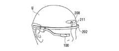
図1は、第1の実施形態にかかるウェアラブル機器用支持部材200を使用者Uが装着した状態を示す上面図である。本実施形態にかかるウェアラブル機器用支持部材200は、使用者Uへの装着状態において、使用者Uの右側頭部に当接するゴム等の弾性体より構成された第1当接部201R、使用者Uの左側頭部に当接するゴム等の弾性体より構成された第2当接部201L、第1当接部201Rと第2当接部201Lとに接続され使用者Uの前頭部に沿って介在する弾性を有する樹脂や金属等により構成されたフレーム部202、フレーム部202にウェアラブル機器100を取り付けて支持する支持部207を備える。ウェアラブル機器用支持部材200は、装着状態において、第1当接部201Rと第2当接部201Lとがフレーム部202の弾性力により使用者Uの頭部方向への力で付勢されることで使用者Uの頭部に固定される。なお、本実施形態では、ウェアラブル機器として表示装置(ニアアイディスプレイ)100を用いている。<First Embodiment>
FIG. 1 is a top view illustrating a state in which a user U wears a wearable
またウェアラブル機器用支持部材200は、第1当接部201Rとフレーム部202とを接続する第1接続部203Rと、第2当接部201Lとフレーム部202とを接続する第2接続部203Lとを備える。さらに第1接続部203Rは、第1当接部201Rから使用者Uの前方に向かって延在する第1延在部204Rと、使用者Uの耳より前方に位置し、且つフレーム部202から使用者Uの後方に向かって延在する第1フレーム延在部205Rを形成するように第1延在部204Rとフレーム部202とを接続する第1分岐部206Rとから構成される。この結果、第1接続部203Rは、上面視において第1分岐部206Rから第1延在部204Rと第1フレーム延在部205Rに二股に分岐して、その間に隙間が形成される。言い換えると、第1延在部204Rと第1フレーム延在部205Rとは、第1分岐部206Rでのみ接続され、第1分岐部206Rから使用者Uの後方側にいくに従い徐々に距離が離れる構成となっている。同様に、第2接続部203Lは、第2当接部201Lから使用者Uの前方に向かって延在する第2延在部204Lと、使用者Uの耳より前方に位置し、且つフレーム部202から使用者Uの後方に向かって延在する第2フレーム延在部205Lを形成するように第2延在部204Lとフレーム部202とを接続する第2分岐部206Lとから構成される。この結果、第2接続部203Lは、上面視において第2分岐部206Lから第2延在部204Lと第2フレーム延在部205Lに二股に分岐して、その間に隙間が形成される。言い換えると、第2延在部204Lと第2フレーム延在部205Lとは、第2分岐部206Lでのみ接続され、第2分岐部206Lから使用者Uの後方側にいくに従い徐々に距離が離れる構成となっている。 The wearable
支持部207は、第1フレーム延在部205R及び第2フレーム延在部205Lの少なくとも一方に配置される。使用者Uの頭部に当接する第1当接部201Rまたは第2当接部201Lの近傍に支持部を設けることで、重量バランス良くウェアラブル機器100を支持することができる。本実施形態では第1フレーム延在部205Rに支持部207を設け、ウェアラブル機器(表示装置)100を取り付けているが、第1フレーム延在部205Rと第2フレーム延在部205Lの両方に支持部207を設け、ウェアラブル機器100を複数取り付ける構成としてもよい。この場合、例えば一方は表示装置、他方は撮像装置を取り付けることで異なる機能をもつウェアラブル機器を同時に装着することができる。ウェアラブル機器として、その他、センサやバッテリーなどを装着してもよい。なお、ウェアラブル機器用支持部材200(支持部207)は、ウェアラブル機器100と同一の筐体で構成し一体としてもよいし、支持部207にウェアラブル機器100が嵌合する溝やねじ止めする機構等の周知の技術を用いてウェアラブル機器100を着脱可能に取り付ける別体構成としてもよい。 The
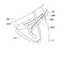
図2は、第1の実施形態にかかるウェアラブル機器用支持部材200及びヘルメット300を使用者Uが装着した状態を示す側面図である。一般的に、ヘルメット300には使用者Uの側頭部から耳の前後、顎を通り、反対側の側頭部へと繋がる耳紐310が付いている。また図3は、第1の実施形態のウェアラブル機器用支持部材200の第1接続部203Rを拡大した斜視図である。なお図3では、支持部207及びウェアラブル機器100は図示されていない。 FIG. 2 is a side view showing a state in which the user U wears the wearable
ウェアラブル機器用支持部材200の第1接続部203Rにおいて、第1延在部204Rと第1フレーム延在部205Rとが上面視において第1分岐部206Rから二股に分岐している。また第1分岐部206Rは、使用者Uへの装着状態において使用者Uの耳より前方に位置している。このような構成により、第1分岐部206Rの後方で第1延在部204Rと第1フレーム延在部205Rとの間に隙間が作られ、ヘルメット300の耳紐310を通すことができる。よって、ウェアラブル機器用支持部材200は、ヘルメット300の耳紐310と干渉することなく、使用者Uに装着することができる。なお、第2接続部203Lに関しても同様の構成により、使用者Uの左側頭部において耳紐310との干渉を回避することができる。 In the
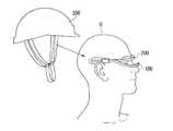
図4A及び図4Bは、第1の実施形態にかかるウェアラブル機器用支持部材200とヘルメット300を装着する順番を示す図である。図4Aは、使用者Uがウェアラブル機器用支持部材200を装着した後にヘルメット300を装着する場合を示す図である。図4Bは、使用者Uがヘルメット300を装着した後にウェアラブル機器用支持部材200を装着する場合を示す図である。 4A and 4B are diagrams illustrating the order in which the wearable
図4Aでは、使用者Uはウェアラブル機器用支持部材200を頭部に装着している。その後に使用者Uは、ヘルメット300を被り、第1延在部204Rと第1フレーム延在部205Rとが上面視において二股構造になっていることによりできた隙間に耳紐310を通す。同様に使用者Uは、第2延在部204Lと第2フレーム延在部205Lとが上面視において二股構造になっていることによりできた隙間に耳紐310を通す。このようにウェアラブル機器用支持部材200及びヘルメット300を装着することで、使用者Uはウェアラブル機器用支持部材200を装着した後にヘルメット300を装着することができる。 In FIG. 4A, the user U wears the wearable
図4Bでは、使用者Uはヘルメット300を頭部に装着している。その後に使用者Uは、ウェアラブル機器用支持部材200を前方から差し込むように側頭部へ装着する。このとき使用者Uは、第1延在部204Rと第1フレーム延在部205Rとが上面視において二股構造になっていることによりできた隙間に耳紐310が通るように装着する。同様に使用者Uは、第2延在部204Lと第2フレーム延在部205Lとが上面視において二股構造になっていることによりできた隙間に耳紐310が通るように装着する。このようにウェアラブル機器用支持部材200及びヘルメット300を装着することで、使用者Uはヘルメット300を装着した後にウェアラブル機器用支持部材200を装着することができる。 In FIG. 4B, the user U wears the
上述の通り、本第1実施形態のウェアラブル機器用支持部材200は、ヘルメット300とともに使用する場合、ヘルメット300を先に装着した状態において後からウェアラブル機器用支持部材200を装着することができ、またウェアラブル機器用支持部材200を先に装着した状態において後からヘルメット300を装着することもできる。すなわち、ウェアラブル機器用支持部材200及びヘルメット300の何れを先に装着してもよく、ウェアラブル機器用支持部材200の装着にあたってその順序に不都合は生じない。 As described above, when the wearable
<第2の実施形態>
次に第2の実施形態のウェアラブル機器用支持部材について説明する。図5は、第2の実施形態にかかるウェアラブル機器用支持部材200及びヘルメット300を使用者Uが装着した状態を示す側面図である。第1の実施形態のウェアラブル機器用支持部材200とは、第1接続部203Rと第2接続部203Lの構造が異なっている。本実施形態にかかるウェアラブル機器用支持部材の第1接続部203Rは、側面視においても、第1分岐部206Rから第1延在部204Rと第1フレーム延在部205Rに二股に分岐している。フレーム部202及び第1フレーム延在部205Rが、第1の実施形態に比べ、第1延在部204Rに対し使用者Uの上方に傾いて配置されている。同様に第2接続部203Lは、側面視においても第2分岐部206Lから第2延在部204Lと第2フレーム延在部205Lに二股に分岐している。フレーム部202及び第2フレーム延在部205Lが、第1の実施形態に比べ、第2延在部204Lに対し使用者Uの上方に傾いて配置されている。<Second Embodiment>
Next, the support member for wearable devices according to the second embodiment will be described. FIG. 5 is a side view showing a state in which the user U wears the wearable
本実施形態のウェアラブル機器用支持部材200は、上述の構成であるため、フレーム部202が使用者Uの視野を遮らない位置に配置される。また第1接続部203Rにおいて、第1延在部204Rと第1フレーム延在部205Rとが側面視においても第2分岐部206Rから二股に分岐していることにより、第1延在部204Rと第1フレーム延在部205Rとの間の隙間に耳紐310を通しやすくなる。第2接続部203Lが配置される使用者Uの左側頭部側についても同様である。 Since the
<第3の実施形態>
次に第3の実施形態のウェアラブル機器用支持部材について説明する。図6は、第3の実施形態のウェアラブル機器用支持部材200を使用者Uが装着した状態を示す上面図である。第1の実施形態のウェアラブル機器用支持部材200とは、第1フレーム延在部205Rと第2フレーム延在部205Lの構造が異なっている。本実施形態にかかるウェアラブル機器用支持部材200の第1フレーム延在部205Rは、第1分岐部206Rに対して着脱可能となっている。同様に第2フレーム延在部205Lは、第2分岐部206Lに対して着脱可能となっている。このような構成であるため、使用者Uはウェアラブル機器用支持部材200及びヘルメット300を装着した後に第1フレーム延在部205R及び第2フレーム延在部205Lを取り付けることができる。従って、ヘルメット300の耳紐が第1フレーム延在部205R及び第2フレーム延在部205Lの外側に配置されないように装着することができる。<Third Embodiment>
Next, a support member for a wearable device according to a third embodiment will be described. FIG. 6 is a top view showing a state in which the user U wears the wearable
図7は第1フレーム延在部205Rと第1分岐部206Rとの着脱機構を示す断面図である。支持部207及びウェアラブル機器100等は図示しない。第1フレーム延在部205Rは断面が円形の円筒型の突起部214を有し、第1分岐部206Rは使用者Uの後方側の端部から前方にかけて断面が円形の溝部215を有する。第1フレーム延在部205Rの突起部214を第1分岐部206Rの溝部215に対して圧入することで、第1分岐部206R(ウェアラブル機器用支持部材200)に対して第1フレーム延在部205R(支持部207及びウェアラブル機器100)を取り付けることができる。なお、第1フレーム延在部205Rと第1分岐部206Rとの着脱方法は、互いに嵌合し合う凹部凸部や溝に限らず、磁石等の周知の技術を用いて着脱可能とすることができる。第2フレーム延在部205Lと第2分岐部206Lとの着脱方法も、同様に周知技術を用いることで着脱可能とする。 FIG. 7 is a cross-sectional view showing an attaching / detaching mechanism between the first
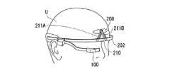
<第4の実施形態>
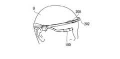
次に第4の実施形態のウェアラブル機器用支持部材について説明する。図8は、第4の実施形態のウェアラブル機器用支持部材200を使用者Uが装着した状態を示す上面図である。また図9は、第4の実施形態のウェアラブル機器用支持部材200及びヘルメット300を使用者Uが装着した状態を示す側面図である。第4の実施形態のウェアラブル機器用支持部材200は、使用者Uの前頭部に当接する第3当接部208が設けられている。また第1当接部201R及び第2当接部201Lは、使用者Uのやや後方側の側頭部に当接する位置に配置されている。具体的には、第1当接部201R及び第2当接部201Lの長手方向(図9では、水平方向)の中心位置Cが使用者Uの耳より後方に位置している。このような構成であるため、使用者Uの前後方向に対してより安定した固定が可能となる。<Fourth Embodiment>
Next, a support member for a wearable device according to a fourth embodiment will be described. FIG. 8 is a top view showing a state where the wearable
図10A〜図10Cは、第3当接部208のスライド部210を説明する図である。また図11は第3当接部208のスライド部210を使用者U側から見た平面図である。図10Aは、第3当接部208を使用者Uの額の高い位置に配置した状態を示す図である。第3当接部208は、2つのスライド部材211A及び211Bで構成されるスライド部210を介してフレーム部202に接続される。2つスライド部材211A及び211Bは、一端がピンで第3当接部208に回動自在に固定されている。また2つのスライド部材211A及び211Bには、スライド部材の長手方向に沿って孔212A及び212Bが形成されている。この孔212A及び212Bがフレーム部202の突起部213A及び213Bに対し取り付けられることで、スライド部材211A及び211Bが摺動自在に取り付けられている。ここで、第3当接部208に使用者Uの下方への力を加えられると、スライド部材211A及び211Bの孔212A及び212Bに沿ってスライド部材とフレーム部202との接続点が移動する。それにともない第3当接部208は、図10Aの位置から図10Bの位置へと移動する。さらに第3当接部208に使用者Uの下方への力が加えられると、第3当接部208は図10Bの位置から図10Cの位置へと移動する。このように第3当接部208が鉛直方向にスライド可能にフレーム部202に固定されていることにより、使用者の頭部の大きさ、形に応じた位置に第3当接部を配置することができる。よって、ウェアラブル機器用支持部材200は、個人差に応じた安定的な固定が可能となる。なお、スライド部の構成は、本実施形態の構成に限らず、凹部と凸部によるスライド機構等を用いてもよい。また、本実施形態ではスライド部210がフレーム部202に対して摺動自在に取り付けられることで第3当接部208が鉛直方向にスライド可能となっているが、図12A及び図12Bに示すように第3当接部208がフレーム部202に固定されたスライド部材211に対してスライドする機構でもよい。スライド部210の機構は、本実施形態の構成に限らず周知の技術を用いてスライド可能とすることができる。 10A to 10C are diagrams illustrating the
次に第4の実施形態の変形例を説明する。図13は、第4の実施形態のウェアラブル機器用支持部材200の変形例を使用者Uが装着した状態を示す上面図である。また図14は、第4の実施形態のウェアラブル機器用支持部材200の変形例及びヘルメット300を使用者Uが装着した状態を示す側面図である。第4の実施形態のウェアラブル機器用支持部材200とは、ゴム等の弾性体の材料より構成された後頭部バンド209を備えている点が異なっている。 Next, a modification of the fourth embodiment will be described. FIG. 13 is a top view illustrating a state in which the user U has mounted a modification of the wearable
後頭部バンド209は、第1フレーム延在部205Rと第2フレーム延在部205Lに取り付けられ、使用者Uの後頭部に沿って当接している。このような構成によって、ウェアラブル機器用支持部材200はより安定的に使用者Uの頭部に固定される。 The
この変形例では、後頭部バンド209は第1フレーム延在部205Rと第2フレーム延在部205Lに取り付けられる構成としたが、第1当接部201Rと第2当接部201Lに取り付けられる構成としてもよい。また後頭部バンド209は、また本実施形態の構成は、第1の実施形態または第2の実施形態にも適用することができる。 In this modified example, the
以上、本発明は、上記実施の形態にのみ限定されるものではなく、幾多の変形または変更が可能である。例えば、ウェアラブル機器100は、映像表示装置に限らず、撮像装置や音楽再生装置等の他のウェアラブル機器であってもよい。また支持部207は、第1フレーム延在部205Rまたは第2フレーム延在部205Lに対して、スライド可能であってもよい。また支持部207は、第1フレーム延在部205Rまたは第2フレーム延在部205Lとの接続点を中心に回動可能であってもよい。またウェアラブル機器用支持部材は、支持部207をスライド、回動可能にすることでウェアラブル機器100の配置を調整することができる。更に、上記実施の形態を組み合わせることも可能である。本発明の要旨を逸脱しない範囲で、種々の変更又は変形が可能である。 As mentioned above, this invention is not limited only to the said embodiment, Many deformation | transformation or a change is possible. For example, the
本発明によれば、ヘルメットや危険を避けるための帽子等の帽体と干渉せず、安定的に使用者の頭部に対してウェアラブル機器を固定するウェアラブル機器用支持部材を提供することができる。 ADVANTAGE OF THE INVENTION According to this invention, the support member for wearable equipment which fixes a wearable apparatus stably with respect to a user's head without interfering with cap bodies, such as a helmet and a hat for avoiding danger, can be provided. .
100 ウェアラブル機器
200 ウェアラブル機器用支持部材
201R 第1当接部
201L 第2当接部
202 フレーム部
203R 第1接続部
203L 第2接続部
204R 第1延在部
204L 第2延在部
205R 第1フレーム延在部
205L 第2フレーム延在部
206R 第1分岐部
206L 第2分岐部
207 支持部
208 第3当接部
209 後頭部バンド
210 スライド部
211 スライド部材
212 孔
213A、213B 突起部
214 突起部
215 溝部
300 ヘルメット
310 耳紐
C 第1当接部(又は第2当接部)の長手方向の中心位置C
U 使用者DESCRIPTION OF
U user
Claims (7)
Translated fromJapanese前記第1当接部とは異なる左右いずれかの側頭部に当接する第2当接部と、
前記第1当接部と前記第2当接部との間で、前記使用者の前頭部に沿って介在するフレーム部と、
前記第1当接部と前記フレーム部とを接続する第1接続部と、
前記第2当接部と前記フレーム部とを接続する第2接続部と、を備え、
前記第1接続部は、前記第1当接部から前記使用者の前方に向かって延在する第1延在部と、前記使用者の耳より前方に位置し、且つ前記フレーム部から前記使用者の後方に向かって延在する第1フレーム延在部を形成するように前記第1延在部と前記フレーム部とを接続する第1分岐部と、を有し、上面視において前記第1分岐部から前記第1延在部と前記第1フレーム延在部に分岐し、
前記第2接続部は、前記第2当接部から前記使用者の前方に向かって延在する第2延在部と、前記使用者の前記耳より前方に位置し、且つ前記フレーム部から前記使用者の後方に向かって延在する第2フレーム延在部を形成するように前記第2延在部と前記フレーム部とを接続する第2分岐部と、を有し、前記上面視において前記第2分岐部から前記第2延在部と前記第2フレーム延在部に分岐し、
前記第1フレーム延在部及び前記第2フレーム延在部の少なくとも一方は、ウェアラブル機器を支持する支持部を備える
ウェアラブル機器用支持部材。A first abutting portion that abuts on either the left or right side of the user;
A second abutting portion that abuts on either the left or right temporal region different from the first abutting portion;
A frame part interposed along the frontal portion of the user between the first contact part and the second contact part;
A first connection portion connecting the first contact portion and the frame portion;
A second connection part for connecting the second contact part and the frame part,
The first connection part is located in front of the user's ear from a first extension part extending from the first contact part toward the front of the user, and from the frame part to the user. A first branch portion connecting the first extension portion and the frame portion so as to form a first frame extension portion extending rearward of the first branch portion, and the first branch in a top view Branch from the first part to the first extension part and the first frame extension part,
The second connection part is located in front of the user's ear from a second extension part extending from the second contact part toward the front of the user, and is used from the frame part to the use. A second branch part connecting the second extension part and the frame part so as to form a second frame extension part extending toward the rear of the person, and the first part in the top view Branching from the two branch parts to the second extension part and the second frame extension part,
At least one of the first frame extension portion and the second frame extension portion includes a support portion that supports a wearable device.
前記第2接続部は、前記側面視において、前記第2分岐部から前記第2延在部と前記第2フレーム延在部に分岐している
請求項1に記載のウェアラブル機器用支持部材。The first connection portion branches from the first branch portion to the first extension portion and the first frame extension portion in a side view,
The support member for wearable device according to claim 1, wherein the second connection part branches from the second branch part to the second extension part and the second frame extension part in the side view.
前記第2フレーム延在部は、前記第2分岐部に着脱可能である
請求項1または2に記載のウェアラブル機器用支持部材。The first frame extension part is detachable from the first branch part,
The support member for wearable device according to claim 1, wherein the second frame extension part is detachable from the second branch part.
請求項1〜3の何れか一項に記載のウェアラブル機器用支持部材。The support member for wearable devices according to any one of claims 1 to 3, further comprising a third contact portion that is connected to the frame portion and contacts the frontal portion of the user.
請求項4に記載のウェアラブル機器用支持部材。The wearable device support member accordingto claim4, wherein the third contact portion is movable in a vertical direction.
請求項1〜5の何れか一項に記載のウェアラブル機器用支持部材。The said 1st contact part and the said 2nd contact part have the center position of the longitudinal direction located behind the said user's said ear in a mounting state, The statement of any one of Claims1-5 . Support member for wearable equipment.
請求項1〜6の何れか一項に記載のウェアラブル機器用支持部材。The wearable device according to any one of claims 1 to 6, further comprising a occipital band attached to the first frame extension portion and the second frame extension portion and abutting along the occipital region of the user. Support member.
Applications Claiming Priority (1)
| Application Number | Priority Date | Filing Date | Title |
|---|---|---|---|
| PCT/JP2014/083115WO2016098153A1 (en) | 2014-12-15 | 2014-12-15 | Support member for wearable device |
Publications (2)
| Publication Number | Publication Date |
|---|---|
| JPWO2016098153A1 JPWO2016098153A1 (en) | 2017-09-21 |
| JP6487463B2true JP6487463B2 (en) | 2019-03-20 |
Family
ID=56126079
Family Applications (1)
| Application Number | Title | Priority Date | Filing Date |
|---|---|---|---|
| JP2016564469AExpired - Fee RelatedJP6487463B2 (en) | 2014-12-15 | 2014-12-15 | Wearable device support member |
Country Status (4)
| Country | Link |
|---|---|
| US (1) | US9977249B2 (en) |
| JP (1) | JP6487463B2 (en) |
| CN (1) | CN107005667B (en) |
| WO (1) | WO2016098153A1 (en) |
Families Citing this family (7)
| Publication number | Priority date | Publication date | Assignee | Title |
|---|---|---|---|---|
| WO2019112850A1 (en) | 2017-12-07 | 2019-06-13 | First-Light Usa, Llc | Head-mounted illumination devices |
| US11144125B2 (en) | 2017-12-07 | 2021-10-12 | First-Light Usa, Llc | Hands-free switch system |
| US12380798B2 (en) | 2020-07-02 | 2025-08-05 | Hourglass Medical Llc | Switch system for operating a controlled device |
| US11553313B2 (en) | 2020-07-02 | 2023-01-10 | Hourglass Medical Llc | Clench activated switch system |
| WO2022173558A1 (en) | 2021-02-12 | 2022-08-18 | Hourglass Medical Llc | Clench-control accessory for head-worn devices |
| EP4327186A1 (en) | 2021-04-21 | 2024-02-28 | Hourglass Medical LLC | Methods for voice blanking muscle movement controlled systems |
| TWI774435B (en)* | 2021-06-22 | 2022-08-11 | 緯創資通股份有限公司 | Headband device |
Family Cites Families (15)
| Publication number | Priority date | Publication date | Assignee | Title |
|---|---|---|---|---|
| JP3352212B2 (en)* | 1994-03-17 | 2002-12-03 | オリンパス光学工業株式会社 | Head mounted video display |
| JP3383733B2 (en) | 1995-10-18 | 2003-03-04 | シャープ株式会社 | Head-mounted display |
| JPH1065996A (en)* | 1996-08-23 | 1998-03-06 | Olympus Optical Co Ltd | Head wearable display device |
| JP2007067497A (en) | 2005-08-29 | 2007-03-15 | Mitsubishi Electric Corp | Mounting device for image display device |
| DE102007053282A1 (en)* | 2007-11-08 | 2009-05-14 | Carl Zeiss Ag | display device |
| US9759917B2 (en)* | 2010-02-28 | 2017-09-12 | Microsoft Technology Licensing, Llc | AR glasses with event and sensor triggered AR eyepiece interface to external devices |
| CN102445768B (en) | 2010-10-01 | 2014-10-08 | 奥林巴斯株式会社 | Device-mounting support member |
| JP2012078588A (en)* | 2010-10-01 | 2012-04-19 | Olympus Corp | Spectacle instrument attachment device |
| JP2013088723A (en)* | 2011-10-20 | 2013-05-13 | Olympus Corp | Mount structure of wearable device, support frame, and mount member |
| JP5363555B2 (en)* | 2011-12-01 | 2013-12-11 | オリンパス株式会社 | Wearable device support member and head-mounted wearable device |
| US8971023B2 (en)* | 2012-03-21 | 2015-03-03 | Google Inc. | Wearable computing device frame |
| US8976085B2 (en)* | 2012-01-19 | 2015-03-10 | Google Inc. | Wearable device with input and output structures |
| JP6076121B2 (en)* | 2013-02-14 | 2017-02-08 | オリンパス株式会社 | Eyeglass frames |
| CN203811928U (en)* | 2014-04-16 | 2014-09-03 | 叶晨光 | Spectacle lens, head-mounted equipment and head-mounted intelligent equipment |
| US9703119B2 (en)* | 2014-08-13 | 2017-07-11 | Google Inc. | Compact folding architecture for head mounted device |
- 2014
- 2014-12-15CNCN201480083662.8Apatent/CN107005667B/ennot_activeExpired - Fee Related
- 2014-12-15JPJP2016564469Apatent/JP6487463B2/ennot_activeExpired - Fee Related
- 2014-12-15WOPCT/JP2014/083115patent/WO2016098153A1/enactiveApplication Filing
- 2017
- 2017-04-24USUS15/494,987patent/US9977249B2/enactiveActive
Also Published As
| Publication number | Publication date |
|---|---|
| US9977249B2 (en) | 2018-05-22 |
| JPWO2016098153A1 (en) | 2017-09-21 |
| US20170227780A1 (en) | 2017-08-10 |
| CN107005667A (en) | 2017-08-01 |
| CN107005667B (en) | 2020-04-10 |
| WO2016098153A1 (en) | 2016-06-23 |
Similar Documents
| Publication | Publication Date | Title |
|---|---|---|
| JP6487463B2 (en) | Wearable device support member | |
| US9503555B2 (en) | Mounting device couplable to a human head | |
| US9039169B2 (en) | Support member for wearable instrument and head-mounted wearable device | |
| US9049896B2 (en) | Detachable safety goggles for safety helmets | |
| US20160045018A1 (en) | Universal retaining device for a mobile multimedia terminal | |
| CN110679142B (en) | Head-mounted display | |
| WO2011132485A1 (en) | Head-mounted video display device | |
| JPWO2017221369A1 (en) | Wearable device | |
| JP5555366B1 (en) | Glasses frame, glasses with wearable computer | |
| JP2013519001A (en) | Headlamp composed of arched headband located on sagittal stitching surface | |
| CN107820710B (en) | Head-mounted display device | |
| CN107894664A (en) | A kind of wearable electronic device | |
| EP3324233A1 (en) | Mounting fixture for wearable device | |
| JP2017038249A (en) | Electronic equipment holder | |
| JP2019123951A (en) | Fixture | |
| KR20160003517U (en) | A head mounted display device having enhanced wearing-feeling | |
| CN107076988B (en) | Eye patch and head-mounted electronic device with same | |
| KR101254468B1 (en) | Head-set for mounting camera module | |
| JP2014007513A (en) | Electronic apparatus | |
| JP5904756B2 (en) | Wearable device support structure | |
| JP2016213638A (en) | Head-mounted display device | |
| JP6421558B2 (en) | Image display device | |
| JP6723383B2 (en) | Image display | |
| KR101327284B1 (en) | Out lens fixing apparatus of goggles | |
| KR20220003010U (en) | Holding Device For Head Mount Display |
Legal Events
| Date | Code | Title | Description |
|---|---|---|---|
| A521 | Request for written amendment filed | Free format text:JAPANESE INTERMEDIATE CODE: A523 Effective date:20171129 | |
| A621 | Written request for application examination | Free format text:JAPANESE INTERMEDIATE CODE: A621 Effective date:20171129 | |
| A521 | Request for written amendment filed | Free format text:JAPANESE INTERMEDIATE CODE: A821 Effective date:20171130 | |
| TRDD | Decision of grant or rejection written | ||
| A01 | Written decision to grant a patent or to grant a registration (utility model) | Free format text:JAPANESE INTERMEDIATE CODE: A01 Effective date:20190205 | |
| A61 | First payment of annual fees (during grant procedure) | Free format text:JAPANESE INTERMEDIATE CODE: A61 Effective date:20190221 | |
| R151 | Written notification of patent or utility model registration | Ref document number:6487463 Country of ref document:JP Free format text:JAPANESE INTERMEDIATE CODE: R151 | |
| R250 | Receipt of annual fees | Free format text:JAPANESE INTERMEDIATE CODE: R250 | |
| R250 | Receipt of annual fees | Free format text:JAPANESE INTERMEDIATE CODE: R250 | |
| LAPS | Cancellation because of no payment of annual fees |