JP6487339B2 - Low profile access port - Google Patents
Low profile access portDownload PDFInfo
- Publication number
- JP6487339B2 JP6487339B2JP2015555266AJP2015555266AJP6487339B2JP 6487339 B2JP6487339 B2JP 6487339B2JP 2015555266 AJP2015555266 AJP 2015555266AJP 2015555266 AJP2015555266 AJP 2015555266AJP 6487339 B2JP6487339 B2JP 6487339B2
- Authority
- JP
- Japan
- Prior art keywords
- access port
- conduit
- receiving cup
- valve
- seal assembly
- Prior art date
- Legal status (The legal status is an assumption and is not a legal conclusion. Google has not performed a legal analysis and makes no representation as to the accuracy of the status listed.)
- Active
Links
- 239000012530fluidSubstances0.000claimsdescription22
- 238000002559palpationMethods0.000claimsdescription20
- 239000000463materialSubstances0.000claimsdescription17
- 229910052751metalInorganic materials0.000claimsdescription7
- 239000002184metalSubstances0.000claimsdescription7
- 238000004891communicationMethods0.000claimsdescription4
- 239000000919ceramicSubstances0.000claimsdescription3
- RTAQQCXQSZGOHL-UHFFFAOYSA-NTitaniumChemical compound[Ti]RTAQQCXQSZGOHL-UHFFFAOYSA-N0.000claimsdescription2
- 125000000218acetic acid groupChemical groupC(C)(=O)*0.000claimsdescription2
- 239000011521glassSubstances0.000claimsdescription2
- 239000011347resinSubstances0.000claimsdescription2
- 229920005989resinPolymers0.000claimsdescription2
- 239000010936titaniumSubstances0.000claimsdescription2
- 229910052719titaniumInorganic materials0.000claimsdescription2
- 238000000034methodMethods0.000claims3
- 238000004519manufacturing processMethods0.000claims1
- 239000012815thermoplastic materialSubstances0.000claims1
- 238000002513implantationMethods0.000description10
- 238000002347injectionMethods0.000description5
- 239000007924injectionSubstances0.000description5
- 238000003780insertionMethods0.000description4
- 230000037431insertionEffects0.000description4
- 238000007920subcutaneous administrationMethods0.000description4
- 229920001169thermoplasticPolymers0.000description4
- 239000004416thermosoftening plasticSubstances0.000description4
- 229920001296polysiloxanePolymers0.000description3
- 238000001802infusionMethods0.000description2
- 150000002739metalsChemical class0.000description2
- 210000005070sphincterAnatomy0.000description2
- 239000000126substanceSubstances0.000description2
- 210000001519tissueAnatomy0.000description2
- 238000012546transferMethods0.000description2
- 210000005166vasculatureAnatomy0.000description2
- WMWLMWRWZQELOS-UHFFFAOYSA-Nbismuth(III) oxideInorganic materialsO=[Bi]O[Bi]=OWMWLMWRWZQELOS-UHFFFAOYSA-N0.000description1
- 238000013461designMethods0.000description1
- 239000003814drugSubstances0.000description1
- 229940079593drugDrugs0.000description1
- 238000003384imaging methodMethods0.000description1
- 206010033675panniculitisDiseases0.000description1
- 230000037361pathwayEffects0.000description1
- 230000002093peripheral effectEffects0.000description1
- 230000000284resting effectEffects0.000description1
- 238000007790scrapingMethods0.000description1
- 238000007789sealingMethods0.000description1
- 238000007711solidificationMethods0.000description1
- 230000008023solidificationEffects0.000description1
- 239000000243solutionSubstances0.000description1
- 210000004304subcutaneous tissueAnatomy0.000description1
- WFKWXMTUELFFGS-UHFFFAOYSA-NtungstenChemical compound[W]WFKWXMTUELFFGS-UHFFFAOYSA-N0.000description1
- 229910052721tungstenInorganic materials0.000description1
- 239000010937tungstenSubstances0.000description1
- 230000002792vascularEffects0.000description1
- 210000003462veinAnatomy0.000description1
Images


Classifications
- A—HUMAN NECESSITIES
- A61—MEDICAL OR VETERINARY SCIENCE; HYGIENE
- A61M—DEVICES FOR INTRODUCING MEDIA INTO, OR ONTO, THE BODY; DEVICES FOR TRANSDUCING BODY MEDIA OR FOR TAKING MEDIA FROM THE BODY; DEVICES FOR PRODUCING OR ENDING SLEEP OR STUPOR
- A61M39/00—Tubes, tube connectors, tube couplings, valves, access sites or the like, specially adapted for medical use
- A61M39/02—Access sites
- A61M39/0208—Subcutaneous access sites for injecting or removing fluids
- A61M2039/0211—Subcutaneous access sites for injecting or removing fluids with multiple chambers in a single site
- A—HUMAN NECESSITIES
- A61—MEDICAL OR VETERINARY SCIENCE; HYGIENE
- A61M—DEVICES FOR INTRODUCING MEDIA INTO, OR ONTO, THE BODY; DEVICES FOR TRANSDUCING BODY MEDIA OR FOR TAKING MEDIA FROM THE BODY; DEVICES FOR PRODUCING OR ENDING SLEEP OR STUPOR
- A61M39/00—Tubes, tube connectors, tube couplings, valves, access sites or the like, specially adapted for medical use
- A61M39/02—Access sites
- A61M39/0208—Subcutaneous access sites for injecting or removing fluids
- A61M2039/0232—Subcutaneous access sites for injecting or removing fluids having means for facilitating the insertion into the body
- A—HUMAN NECESSITIES
- A61—MEDICAL OR VETERINARY SCIENCE; HYGIENE
- A61M—DEVICES FOR INTRODUCING MEDIA INTO, OR ONTO, THE BODY; DEVICES FOR TRANSDUCING BODY MEDIA OR FOR TAKING MEDIA FROM THE BODY; DEVICES FOR PRODUCING OR ENDING SLEEP OR STUPOR
- A61M39/00—Tubes, tube connectors, tube couplings, valves, access sites or the like, specially adapted for medical use
- A61M39/02—Access sites
- A61M39/0208—Subcutaneous access sites for injecting or removing fluids
- A61M2039/0235—Subcutaneous access sites for injecting or removing fluids having an additional inlet, e.g. for a guidewire or a catheter tube
- A—HUMAN NECESSITIES
- A61—MEDICAL OR VETERINARY SCIENCE; HYGIENE
- A61M—DEVICES FOR INTRODUCING MEDIA INTO, OR ONTO, THE BODY; DEVICES FOR TRANSDUCING BODY MEDIA OR FOR TAKING MEDIA FROM THE BODY; DEVICES FOR PRODUCING OR ENDING SLEEP OR STUPOR
- A61M39/00—Tubes, tube connectors, tube couplings, valves, access sites or the like, specially adapted for medical use
- A61M39/02—Access sites
- A61M39/0208—Subcutaneous access sites for injecting or removing fluids
- A61M2039/0238—Subcutaneous access sites for injecting or removing fluids having means for locating the implanted device to insure proper injection, e.g. radio-emitter, protuberances, radio-opaque markers
- Y—GENERAL TAGGING OF NEW TECHNOLOGICAL DEVELOPMENTS; GENERAL TAGGING OF CROSS-SECTIONAL TECHNOLOGIES SPANNING OVER SEVERAL SECTIONS OF THE IPC; TECHNICAL SUBJECTS COVERED BY FORMER USPC CROSS-REFERENCE ART COLLECTIONS [XRACs] AND DIGESTS
- Y10—TECHNICAL SUBJECTS COVERED BY FORMER USPC
- Y10T—TECHNICAL SUBJECTS COVERED BY FORMER US CLASSIFICATION
- Y10T29/00—Metal working
- Y10T29/49—Method of mechanical manufacture
- Y10T29/49826—Assembling or joining
Landscapes
- Health & Medical Sciences (AREA)
- Heart & Thoracic Surgery (AREA)
- Hematology (AREA)
- Engineering & Computer Science (AREA)
- Anesthesiology (AREA)
- Biomedical Technology (AREA)
- Pulmonology (AREA)
- Life Sciences & Earth Sciences (AREA)
- Animal Behavior & Ethology (AREA)
- General Health & Medical Sciences (AREA)
- Public Health (AREA)
- Veterinary Medicine (AREA)
- Infusion, Injection, And Reservoir Apparatuses (AREA)
- Media Introduction/Drainage Providing Device (AREA)
- Materials For Medical Uses (AREA)
Description
Translated fromJapanese[0001]本願は、2013年1月23日に出願された、「低プロファイルのアクセスポート」という表題の米国仮特許出願第61/755,913号の利益を主張する。この出願の全ての内容は、参照によって本明細書に組み入れられる。 [0001] This application claims the benefit of US Provisional Patent Application No. 61 / 755,913, filed January 23, 2013, entitled "Low Profile Access Port". The entire contents of this application are incorporated herein by reference.
[0002]簡単に要約すると、本発明の実施形態は、患者の体内に皮下移植(埋め込み)するための低プロファイルのアクセスポートを対象としている。このアクセスポートは、カテーテル付きニードルが困難性なくポートにアクセスすることができるようにするために、比較的大きな皮下ターゲットを提供する受入カップを備えている。さらに、アクセスポートは、逆流を防止しつつ、ポートを通る加圧流体の注入を許容するために、バルブ/シールアセンブリを備えている。 [0002] Briefly summarized, embodiments of the present invention are directed to low profile access ports for subcutaneous implantation (implantation) in a patient's body. The access port includes a receiving cup that provides a relatively large subcutaneous target to allow the catheterized needle to access the port without difficulty. In addition, the access port includes a valve / seal assembly to allow injection of pressurized fluid through the port while preventing backflow.
[0003]したがって、一実施形態では、低プロファイルのアクセスポートは、導管を有する本体を備えている。導管は、その近位端に入口ポートを備えている。本体は、さらに、受入カップを備えている。受入カップは、入口ポートを介してカテーテル付きニードルを導管に方向付けるために、窪んだ形状を有している。受入カップは、ニードルを皮膚表面に容易に衝突させるために、患者内に皮下に埋め込まれるときに実質的に皮膚表面に向けられる。導管内に配置されるバルブ/シールアセンブリは、逆流を防止しつつ、カテーテルがバルブ/シールアセンブリを通ることを可能にする。 [0003] Accordingly, in one embodiment, the low profile access port comprises a body having a conduit. The conduit has an inlet port at its proximal end. The main body further includes a receiving cup. The receiving cup has a recessed shape for directing the catheterized needle through the inlet port into the conduit. The receiving cup is substantially directed to the skin surface when implanted subcutaneously in the patient in order to easily impact the needle against the skin surface. A valve / seal assembly disposed within the conduit allows the catheter to pass through the valve / seal assembly while preventing backflow.
[0004]本発明の実施形態のこれらおよび他の特徴は、以下の説明および添付の特許請求の範囲から更に明らかになり、あるいは、本発明の実施形態を以下に説明するように実施することによってわかるであろう。 [0004] These and other features of embodiments of the present invention will become more apparent from the following description and the appended claims, or by implementing the embodiments of the present invention as described below. You will understand.
[0005]添付図面に示す本開示の特定の実施形態を参照して、本開示を更に詳細に説明する。添付図面は、本発明の典型的な実施形態を図示しているに過ぎず、従って、本発明の範囲を限定するものではないと捉えられることが理解されよう。添付図面を使用して本発明の例示的な実施例について更に詳細に説明する。 [0005] The present disclosure will be described in more detail with reference to specific embodiments of the present disclosure shown in the accompanying drawings. It will be understood that the accompanying drawings are merely illustrative of exemplary embodiments of the invention and are therefore not to be construed as limiting the scope of the invention. The exemplary embodiments of the present invention will be described in more detail with reference to the accompanying drawings.
[0014]次に添付図面を参照すると、これらの図では、同様の構造に同じ参照符号が付してある。添付図面は、本発明の例示的な実施形態の概略図であり、限定を意図したものではなく、必ずしも縮尺通りではないということが理解されよう。 [0014] Referring now to the accompanying drawings, in which like structures are designated with like reference numerals. It will be understood that the accompanying drawings are schematic illustrations of exemplary embodiments of the invention and are not intended to be limiting and are not necessarily to scale.
[0015]明瞭にするために、「近位」という用語は、本明細書中に説明するデバイスを使用する臨床医に相対的に近い方向をいうのに対し、「遠位」という用語は、臨床医から相対的に離れる方向をいうことを理解されるべきである。例えば、患者の体内に配置されたカテーテルの端部は、カテーテルの遠位端であると見なされるのに対し、体外に留まるカテーテルの端部は、カテーテルの近位端であると見なされる。また、特許請求の範囲を含む本明細書中で使用されているように、「備える」(including)、「有する」(has)および「有している」(having)といった用語は、「備える」(comprising)という用語と同じ意味を有する。 [0015] For clarity, the term "proximal" refers to a direction that is relatively close to the clinician using the devices described herein, whereas the term "distal" It should be understood that it refers to the direction away from the clinician. For example, the end of a catheter placed within a patient's body is considered the distal end of the catheter, while the end of the catheter that remains outside the body is considered the proximal end of the catheter. Also, as used herein, including the claims, the terms “including”, “has”, and “having” It has the same meaning as the term (comprising).
[0016]本発明の実施形態は、概して、患者の体内に皮下に埋め込むためのアクセスポートを対象としている。埋め込まれるアクセスポートは、カテーテル付きニードル(例えば、末梢静脈(「PIV」)カテーテルによって経皮的にアクセス可能である。その結果、PIVカテーテルは、アクセスポートと流体連通する。アクセスポートの流体出口は、一実施形態では、PIVカテーテルを介して患者の血管系から流体を注入および/または除去することができるようにするために、患者の血管系内に配置される留置カテーテルに動作可能に接続される。 [0016] Embodiments of the present invention are generally directed to an access port for subcutaneous implantation in a patient's body. The implanted access port is accessible percutaneously by a catheterized needle (eg, a peripheral vein (“PIV”) catheter) so that the PIV catheter is in fluid communication with the access port. , In one embodiment, operatively connected to an indwelling catheter disposed within the patient's vasculature to allow fluid to be infused and / or removed from the patient's vasculature via the PIV catheter. The
[0017]一実施形態にしたがって、アクセスポートは、患者の皮下組織内に容易に配置することができるように、低プロファイルに形成される。さらに、アクセスポートは、PIVカテーテルまたは他の適切なカテーテル付きニードルが困難性なくポートにアクセスできるようにするために、比較的大きな皮下ターゲットを提供するように構成される。さらに、アクセスポートは、比較的高流量(例えば、約300psiの圧力において5ml/秒)でアクセスポートを通る流体の注入(本明細書では、「高圧注入」とも呼ぶ)を許容するために、バルブ/シールアセンブリを備えている。本明細書で説明されるアクセスポートのための実施可能な用途には、薬剤および他の流体を患者に投与すること、フェレーシス、流体吸引などが含まれる。 [0017] According to one embodiment, the access port is formed with a low profile so that it can be easily placed in the subcutaneous tissue of a patient. In addition, the access port is configured to provide a relatively large subcutaneous target to allow a PIV catheter or other suitable catheterized needle to access the port without difficulty. In addition, the access port has a valve to allow fluid injection (also referred to herein as “high pressure injection”) through the access port at a relatively high flow rate (eg, 5 ml / sec at a pressure of about 300 psi). A seal assembly is provided. Possible applications for the access ports described herein include administering drugs and other fluids to a patient, pheresis, fluid aspiration, and the like.
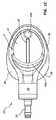
[0018]まず、図1A〜1Eを参照すると、一実施形態にしたがったアクセスポートの様々な詳細が全体的に符号10を付して示されている。図示するように、ポート10は、本体12を備えている。本体12は、本実施形態では、第1の部分12Aと第2の部分12Bとによって形成されている(図1E)。本実施形態では、ポート本体12は、チタンなどの金属を含有しており、第2の部分12Bは、圧入されて第1の部分12Aと係合し、それによって本体を形成する。ただし、ポート本体は、金属、熱可塑性物質、セラミックスなど、他の様々な材料を含有していてもよい。 [0018] Referring first to FIGS. 1A-1E, various details of an access port according to one embodiment are shown generally at 10. As illustrated, the
[0019]本実施形態では、ポート本体12は、以下でさらに説明されるようにカテーテル付きニードル(図2)を受け入れて方向付けてポート10と動作可能に接続するための実質的に窪んだ形状を有する受入カップ14を備えている。詳細には、実質的に窪んだ形状の受入カップ14は、カテーテル付きニードル(図2)を方向付けて、入口ポート16に向けて受入カップ14に衝突させるように構成されている。入口ポート16は、ポート本体12によって形成される導管18のための開口として機能する。受入カップ14の開口した浅い特質は、その実質的に上向きの方向性(すなわち、患者の皮膚表面に向かう)と相まって、患者の皮膚の下に経皮的に埋め込まれるときに皮膚表面と実質的に平行になり(すなわち、受入カップは、皮膚が指圧または触診によって静止または変形していないときに、皮膚表面と実質的に平行である)、それによって、図2に示されるように、皮膚内に導入されるときに、受入カップは、ニードルのための大きな容易にアクセス可能なターゲットを提供することができる。図2は、さらに、ポート10が比較的低プロファイルの高さを形成することを示している。これによって、埋め込み後にポートにアクセスするために使用されるニードルの長さを比較的短くすることができる。 [0019] In this embodiment, the
[0020]ポート本体12は、臨床医が、患者の皮膚の下への埋め込みの後、指での触診によってポート10の位置特定および/または同定を行うことを補助するために、触診構造26を備えている。詳細には、本実施形態における触診構造26は、受入カップ14の近位端の近傍に配置された突起部26Aと、受入カップの遠位部分の上方に配置されるとともに当該遠位部分の周りで湾曲した頂部26Bと、を備えている。図1Bは、触診構造が、受入カップ14の位置および/または向きを特定するための臨床医による触診構造の触診を容易にするように、ポート10によって形成される全体的に上部の平面の上方に延在することを示している。本明細書で図示され説明されているものに加えて、ポート上には、触診構造の他の様々なサイズ、構成、数などが備えられていてもよいことに留意されたい。 [0020]
[0021]ガイド溝28が、受入カップ14に形成されており、導管18の入口ポート16と長手方向に整合している。ガイド溝28は、受入カップ14の表面の隣接する部分に対して高さが低くなった部分として形成されており、ニードルがガイド溝に衝突されるとカテーテル付きニードルの遠位先端を入口ポート16に向けて案内するための案内経路を提供するように、受入カップの近位端から受入カップの表面に沿って遠位方向に延在している。これによって、挿入中にニードルが受入カップ14を横切って滑り、受入カップ14から外れることが抑制される。形状および構成が異なっていても、これらおよび他の類似の構成が本明細書に開示される他のポートにも備えられていてもよい。 [0021] A
[0022]図1Eで最もよく分かるように、ポート本体12は、さらに、カテーテルをポート10に流体連通させるように経皮的に挿入されるカテーテルが通ることができる経路としての導管18を形成する。図示するように、導管18は、入口ポート16を介して受入カップ14に連通する。導管18の第1の導管部分18Aは、図1Eに示される全体視から下向きに角度付けられた方向に、入口ポート16から遠位方向に屈曲部30まで延在する。屈曲部30では、導管の第2の導管部分18Bが、わずかに上向きに角度付けられ、予め定められた角度θ1で方向が変化している。一実施形態における配向角度θ1は、約37度であるが、他の実施形態ではこれから変えることができ、一実施形態では、37度未満の角度が含まれることに留意されたい。角度θ1の大きさは、一実施形態では、様々な要因に依存し、このような要因には、ポート導管に挿入されるべきカテーテルおよび/またはニードルのサイズ、導管そのもののサイズなどが含まれる。[0022] As best seen in FIG. 1E, the
[0023]次いで、導管18は、ポート本体のバルブハウジング20によって形成されるキャビティ20Aまで、当該キャビティ20Aを通って延在している。導管18は、ポート10のステム24の遠位解放端まで延在している。導管18は、理解されるように、カテーテル40(図2)が導管18を通ることができるようなサイズを有している。 [0023] The
[0024]既に述べたように、バルブハウジング20は、導管が通るキャビティ20Aを形成する。キャビティ20Aは、バルブ/シールアセンブリ22を収容する。バルブ/シールアセンブリ22は、シール要素すなわちシール部32を備えている。シール部32は、カテーテル40が通ることができる中央穴を形成する。バルブ/シールアセンブリ22は、さらに、第1のスリットバルブ34Aと第2のスリットバルブ34Bとを備えている。一実施形態では、図1Eに示されるように、シール部32およびバルブ34A,34Bは、一緒に挟み込まれ、キャビティ20A内の適所に固定される。スリットバルブ34A,34Bのスリットは、本実施形態では、約90度だけ互いから回転的にオフセットされているが、他の関係も可能である。 [0024] As already mentioned, the
[0025]バルブ/シールアセンブリ22のシール部32およびバルブ34A,34Bは、協働して、バルブ/シールアセンブリを通る流体の逆流も防止しつつ、カテーテル40(図2)がそこを通る流体密な通過を可能にする。実際、一実施形態では、本明細書に開示されるシール部によって、カテーテルがシールを通って配置されるときのカテーテルの外部の周りでの流体流れを防止する。一方、バルブは、カテーテルがバルブを通らないときに流体流れを防止するのに適している。このようにして、カテーテル40が挿入されていないときに、バルブ/シールアセンブリ22は、空気または流体の通過を防止するためにシールする。本実施形態では、シール部32およびバルブ34A,34Bは、シリコーンを含有しているが、他の適切な順応性のある材料が使用されてもよい。 [0025] The
[0026]本実施形態におけるポート10は、ポート本体12を覆う被覆部36を備えている。被覆部36は、シリコーンまたは他の適切な順応性のある材料を含有しており、ポート10のための比較的柔軟な表面を提供するとともにポートの埋め込みの後に患者の不快感を低減するように、図示するように本体12を取り囲む。被覆部36は、図1Cで最もよく分かるように、ポート10を患者の組織に縫い合わせるために、予め定められた2つの縫合位置38を備えている。ただし、縫合部は、必要に応じて、被覆部の他の部分を通されてもよい。被覆部36は、さらに、埋め込みの後に組織ポケット内でのその位置におけるポート10のための安定表面を提供するように、比較的平坦な底面36Aを備えている。これとは対照的に、図3Cに示されるポートは、わずかに丸みのあるプロファイルを有する底面を備えている。 [0026] The
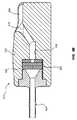
[0027]図2は、一実施形態による、ニードル42上に配置されたカテーテル40の挿入に関する詳細を示している。触診構造26の皮膚触診によってポート10の位置を特定した後、臨床医は、図示するように、カテーテル付きニードル42を使用して皮膚表面44を穿刺し、ニードルの遠位先端42Aが受入カップ14の一部分に衝突するまでニードルを挿入する。受入カップ14の向きが皮膚表面と実質的に平行なので、ニードル42は、比較的急な挿入角度θ2で受入カップに衝突することができることに留意されたい。これによって、身体内へのニードルの挿入が容易になる。実際、一実施形態では、患者の皮膚を通って実質的に直角に挿入されるニードルは、アクセスポートの受入カップに衝突することができる。[0027] FIG. 2 shows details regarding insertion of a
[0028]ニードル42は、遠位先端42Aがガイド溝28内に受け入れられるまで操作される。これによって、遠位先端が溝に沿って入口ポート16まで案内され得る。次いで、ニードル42は、屈曲部30によって停止されるまで、入口ポート16を通って導管18の第1の部分18Aに挿入される。次いで、ニードル42は、僅かな距離だけ近位方向に後退され、カテーテル40は、カテーテルが曲がって屈曲部30を越えて前進し、導管18の第2の部分18Bに入るように、ニードルを越えて前進される。カテーテル40の遠位端40Aが前進してシール部32の穴に入り、当該穴を越えて、バルブ/シールアセンブリ40のスリットバルブ34A,34Bの両方のスリットを通るように、カテーテルの前進が継続される。カテーテル40の遠位端40Aがバルブ/シールアセンブリ22を越えて遠位方向に延在すると、さらなる前進が中止され、カテーテル40およびポート10を通る流体移送(ステム24を介しての注入および/または吸引が含まれる)が開始され得る。流体移送が完了されると、カテーテル40は、バルブ/シールアセンブリ22を通って近位方向に引き抜かれることができ、次いで、導管は、皮膚の表面44を通って患者の外部に引き抜かれる。 [0028] The
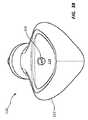
[0029]図3A〜3Cは、他の実施形態によるアクセスポート110の詳細を示している。ポート10と、図示され本明細書で説明される他のポートと、の間には、様々な類似点が存在する。このように、選択されたポートの態様のみが以下で説明される。図示するように、ポート110は、図3Cで最もよく分かるように、第1の本体部分112Aと第2の本体部分112Bとを有する本体112を備えている。本実施形態における本体112は、熱可塑性物質(例えば、本実施形態ではアセチル樹脂)を含有している。このように、本実施形態では、第1の本体部分112Aおよび第2の本体部分112Bは、互いに超音波溶接されて、本体12を形成する。上述したように、本体112は、受入カップ114を備えており、受入カップ114は、入口ポート116を介して導管118に動作可能に接続される。また、ポート本体、受入カップ、導管などを形成するために様々な材料を使用することができることに留意されたい。 [0029] FIGS. 3A-3C illustrate details of an
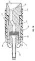
[0030]バルブ/シールアセンブリ122は、バルブハウジング120によって形成されるキャビティ120A内に配置される。キャビティ120Aは、本実施形態では、第1の本体部分112Aによって形成される。バルブ/シールアセンブリ122は、カテーテルが通過するための中央穴を有する近位シール部132と、互いに対して90度オフセットされて配置されたスリットをそれぞれが有する2つのスリットバルブ134A,134Bと、中央穴を有する遠位シール部135(本明細書では、括約筋シール部とも呼ぶ)と、を備えている。 [0030] The valve /
[0031]遠位シール部135は、その遠位表面に、シール部の中央穴のまわりに配置された円錐台部分135Aを備えている。円錐台部分135Aは、カテーテルがバルブ/シールアセンブリを通って延在するときに、カテーテルの外表面の周りを括約筋状にシールする。円錐台部分135Aは、より緊密な係合においてでさえ、円錐台部分に衝突する逆流流体によってシール部をカテーテルの外表面の周りで自己固定させるように配置される。したがって、高い流体圧力が存在するとき(例えば、高圧注入の場合)に、カテーテルの外表面を越えて逆流することが防止される。既に述べたように、他のバルブ/シール部の組み合わせもバルブ/シールアセンブリに含まれ得る。 [0031] The
[0032]本実施形態では、受入カップ114と、バルブ/シールアセンブリ122に対して近位側の導管118の一部分とは、両方とも、ニードルが突き通すことができないライニングを備えている。このライニングは、そこに衝突するときに、ニードルの遠位端が表面を削り取ることを防止する。これによって、ニードルによって掘られた物質の破片が望ましくなく生成されることが防止される。ニードルが突き通すことができない材料のために、様々な適切な材料を使用することができ、このような材料には、ガラス、セラミック、金属等が含まれる。一実施形態では、ポート110の構成要素は、ポートがMRIで安全と見なされるように、全て非金属であり、それによって、ポートが患者内に埋め込まれている場合に、患者について撮影されるMRI画像において望ましくないアーチファクトが生成されない。 [0032] In this embodiment, the receiving
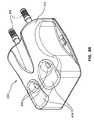
[0033]図4は、他の実施形態によるポート110の追加的な特徴を示している。図示するように、本実施形態では、受入カップ18は、ポート110の特性を表示するために、X線不透過性の印128を備えている。ここで、X線不透過性の印128は、X線撮像技術を使用してポートの埋め込み後に見ることができるように、X線不透過性の材料(例えば、タングステン、三酸化ビスマスなど)によって形成される「C」および「T」を有している。例えば、X線不透過性の材料は、固化前にポート本体のキャビティに注入される最初は流れることができる材料などとして、ポート本体に含まれるインサート成形されたインサートとして形成され得る。ポート本体が金属である場合の実施形態では、X線不透過性の印は、X線画像において目立つ、X線で識別可能なコントラストを作り出すように、エッチング、彫刻、または、印と、取り囲むポート本体材料と、の間の相対的な厚みの違いを作り出すことによって、形成され得る。 [0033] FIG. 4 illustrates additional features of the
[0034]本実施形態では、CTのX線不透過性の印128は、ポートがそこを通る流体の高圧注入を行うことができることを観察者に表示する。当業者には理解されるように、この特性に加えて、他の特性が他の様々な種類の印によって表示されてもよい。 [0034] In this embodiment, the CT
[0035]さらに、本実施形態では、図4のポート110の上面図は、受入カップ114を取り囲む領域においてポート112が略三角形を形成することを示している。この領域は、埋め込みの後に臨床医によって触診され得るとともに、受入カップの位置だけでなく、ポートの特定の特性(例えば、高圧注入のために使用されるその能力)も表示することができる。勿論、受入カップは、他の実施形態では、三角形以外の形状を形成してもよい。 [0035] Further, in this embodiment, the top view of the
[0036]図4は、さらに、3つの触診構造126、すなわち、ポート本体112に形成された対応する穴に配置される3つの縫合プラグ126Aが、受入カップ114の表面の周りに分散されていることを示している。これらの縫合プラグ126Aは、本実施形態では、立ち上がったシリコーンの突起部を備えており、患者にニードルを挿入する前に臨床医によってそれらが触診されるときに、埋め込み後の受入カップ114の位置を特定するのに役立つ。他の実施形態では、他の様々な触診構造がポートに備えられていてもよい。 [0036] FIG. 4 further illustrates that three
[0037]図5は、一実施形態による低プロファイルのポート210の詳細を示している。このポート210は、窪んだ形状の受入カップ214を形成する本体212と、受入カップに対して中央から僅かにずらされて位置決めされた入口ポート216と、を備えている。ステム224が、流体出口として備えられている。 [0037] FIG. 5 shows details of a
[0038]図6は、一実施形態による低プロファイルのポート210を示している。本体212は、追加的な表面構成を形成し、受入カップ214に対して遠位側で立ち上がった触診構造226を備えている。図5および図6を考慮すると、血管アクセスを提供するための低プロファイルの解決策を提供するために、ポートは様々な形状および構成で構成されることができることが理解される。受入カップの形状、デザインおよび構成は、本明細書で明示的に図示され説明されるものから変わり得ることにも留意されたい。 [0038] FIG. 6 illustrates a
[0039]図7Aおよび図7Bは、本実施形態による低プロファイルの2つの本体を有する、アクセスポート310の様々な詳細を示している。ポート本体312の各々は、側方を向くとともに導管318の先端に入口ポート316を備える受入カップ314を形成する。導管318は、バルブハウジング320内に配置されたバルブ/シールアセンブリ322まで遠位方向に延在する。導管318は、本実施形態では、本体312の一部分によって形成される。導管318は、ポート324を通って延在する。順応性のある被覆部324がポート310の各々の本体312の部分を覆っており、本体同士を動作可能に連結している。本体312は、任意の適切な材料を含有していてもよく、こうした材料には、金属、熱可塑性物質などが含まれる。 [0039] FIGS. 7A and 7B show various details of an
[0040]図8Aおよび図8Bは、本実施形態による低プロファイルの2つの本体を有する、アクセスポート410の様々な詳細を示している。ポート本体412は、2つの流体経路を形成する。流体経路の各々は、本体412によって形成されるとともに図8Aおよび図8Bに示される全体視から実質的に上向きに向けられた受入カップ414を備えている。受入カップ414の各々は、入口ポート416を備えており、入口ポート416は、導管418への開口を形成する。導管418の各々は、バルブハウジング420内に配置されたバルブ/シールアセンブリ422まで遠位方向に延在する。導管418は、本実施形態では、本体412の一部分によって形成される。導管418は、ポート424を通って延在する。本体412は、任意の適切な材料を含有していてもよく、こうした材料には、金属、熱可塑性物質などが含まれる。 [0040] FIGS. 8A and 8B show various details of an
[0041]本発明の実施形態は、本開示の趣旨から逸脱することなく、その他の特定の形態で実施されてもよい。説明された実施形態は、全ての点に関し、単なる例示であって限定的ではないと考えられるべきである。従って、本実施形態の範囲は、上記の説明によってではなく、添付の特許請求の範囲によって示される。特許請求の範囲と等価の意味および範囲内の全ての変更は、特許請求の範囲の範疇に含まれる。 [0041] Embodiments of the invention may be implemented in other specific forms without departing from the spirit of the disclosure. The described embodiments are to be considered in all respects only as illustrative and not restrictive. The scope of the embodiments is, therefore, indicated by the appended claims rather than by the foregoing description. All changes that come within the meaning and range of equivalency of the claims are to be embraced within their scope.
10,110,210,310,410…アクセスポート
12,112,212,312,412…ポート本体
12A,112A…第1の本体部分
12B,112B…第2の部分
14,114,214,314,414…受入カップ
16,116,216,316,416…入口ポート
18,118,318,418…導管
18A…第1の導管部分
18B…第2の導管部分
20,120,320,420…バルブハウジング
20A,120A…キャビティ
24,224…ステム
26,126,226…触診構造
26A…突起部
26B…頂部
28…ガイド溝
30…屈曲部
32,132…シール部
34A,134A…第1のスリットバルブ
34B…第2のスリットバルブ
36…被覆部
36A…底面
38…縫合位置
40…カテーテル
40A…遠位端
42…ニードル
42A…遠位先端
44…表面
126A…プラグ
128…印
135…遠位シール部
135A…円錐台部分
324…被覆部
424…ポート
22,122,322,422…バルブ/シールアセンブリ10, 110, 210, 310, 410 ...
Claims (23)
Translated fromJapanese本体を備え、
前記本体は、
導管であって、該導管の近位端に入口ポートを備える導管と、
前記入口ポートと連通する受入カップと
を備え、
前記受入カップは、
窪んだ形状の面を形成し、
前記入口ポートを介して前記導管内にカテーテル付きニードルの衝突遠位先端を方向付けるために、前記面において高さが低くなった部分を形成するガイド溝を備え、
前記患者内に皮下に埋め込まれるときに実質的に皮膚表面に向けられる受入カップと
を備え、
前記アクセスポートは、さらに、前記導管内に配置されるバルブ/シールアセンブリであって、該バルブ/シールアセンブリを通ってカテーテルが通過することができるバルブ/シールアセンブリを備える
アクセスポート。A low profile access port for placement under the skin of a patient,
With a body,
The body is
A conduit comprising an inlet port at a proximal end of the conduit;
A receiving cup in communication with the inlet port,
The receiving cup is
Forming a recessed surface,
A guide groove forming a reduced height portion on the surface for directing a colliding distal tip of a catheterized needle into the conduit via the inlet port;
A receiving cup that is substantially directed to the skin surface when implanted subcutaneously in the patient;
The access port further comprises a valve / seal assembly disposed within the conduit, the valve / seal assembly allowing a catheter to pass through the valve / seal assembly.
前記導管は、第1の導管部分と第2の導管部分とを備え、
前記第2の導管部分は、前記カテーテルの通過を許容しつつ前記カテーテル付きニードルの前記ニードルの通過を防止するように、前記第1の導管部分に対して遠位側に前記第1の導管部分に対して角度付けられて位置決めされる
アクセスポート。The access port according to claim 1,
The conduit comprises a first conduit portion and a second conduit portion;
The second conduit portion is distal to the first conduit portion so as to prevent passage of the needle with the catheter while allowing passage of the catheter. An access port that is positioned at an angle to.
前記第2の導管部分は、前記第1の導管部分に対して約37度未満の角度で配置される
アクセスポート。The access port according to claim 2,
The second conduit portion is disposed at an angle of less than about 37 degrees with respect to the first conduit portion.
前記受入カップは、前記アクセスポートが皮下に埋め込まれるときに、前記皮膚表面と実質的に平行に位置決めされる
アクセスポート。The access port according to claim 1,
The receiving cup is positioned substantially parallel to the skin surface when the access port is implanted subcutaneously.
前記患者の前記皮膚を通して実質的に垂直に挿入されるニードルは、前記アクセスポートの前記受入カップに衝突することができる
アクセスポート。The access port according to claim 4,
A needle that is inserted substantially vertically through the skin of the patient can impact the receiving cup of the access port.
前記導管は、前記受入カップから前記アクセスポートのステムの出口まで延在し、
前記アクセスポートは、さらに、前記皮下に埋め込まれるアクセスポートの位置を臨床医が触診することができるようにするための少なくとも1つの触診構造を備える
アクセスポート。The access port according to claim 1,
The conduit extends from the receiving cup to an outlet of the stem of the access port;
The access port further comprises at least one palpation structure to allow a clinician to palpate the location of the access port implanted under the skin.
前記少なくとも1つの触診構造は、前記受入カップの近傍に配置される頂部と突起部とを備える
アクセスポート。The access port according to claim 6, wherein
The access port, wherein the at least one palpation structure comprises a top and a protrusion disposed in the vicinity of the receiving cup.
前記少なくとも1つの触診構造は、前記受入カップの近傍に配置される少なくとも1つの縫合穴プラグを備える
アクセスポート。The access port according to claim 6, wherein
The access port, wherein the at least one palpation structure comprises at least one suture hole plug disposed proximate to the receiving cup.
前記アクセスポートの前記本体は、前記受入カップのまわりに三角形の形状を実質的に形成する
アクセスポート。The access port according to claim 1,
The body of the access port substantially forms a triangular shape around the receiving cup.
前記バルブ/シールアセンブリは、互いに対して挟み込まれた構成で位置決めされる、第1のシール部と第1のスリットバルブと第2のスリットバルブとを備える
アクセスポート。The access port according to claim 1,
The valve / seal assembly comprises an access port comprising a first seal portion, a first slit valve and a second slit valve positioned in a sandwiched configuration relative to each other.
前記受入カップの少なくとも一部分は、ニードルが突き通すことができない材料を含有する
アクセスポート。The access port according to claim 1,
An access port wherein at least a portion of the receiving cup contains a material that the needle cannot penetrate.
前記ニードルが突き通すことができない材料には、金属とガラスとセラミックとのうちの少なくとも1つが含まれる
アクセスポート。The access port according to claim 11,
The material that the needle cannot penetrate includes at least one of metal, glass, and ceramic.
前記本体は、金属と熱可塑性物質とのうちの少なくとも一方を含有する
アクセスポート。The access port according to claim 1,
The access port includes at least one of a metal and a thermoplastic material.
前記本体の少なくとも一部分は、チタンとアセチル樹脂とのうちの少なくとも一方を含有する
アクセスポート。The access port according to claim 13,
At least a part of the main body contains at least one of titanium and acetyl resin.
前記入口ポートは、前記受入カップにおいて実質的に中央に位置する
アクセスポート。The access port according to claim 14, wherein
The inlet port is an access port located substantially centrally in the receiving cup.
前記本体は、少なくとも、第1の受入カップと第2の受入カップとを形成し、
前記第1の受入カップおよび前記第2の受入カップの各々は、入口ポートを介して導管と連通し、
前記導管の各々は、該導管内に配置されたバルブ/シールアセンブリを有する
アクセスポート。The access port according to claim 1,
The body forms at least a first receiving cup and a second receiving cup;
Each of the first receiving cup and the second receiving cup communicates with a conduit via an inlet port;
Each of the conduits has an access port having a valve / seal assembly disposed within the conduit.
前記アクセスポートの第1の本体部分および第2の本体部分を用意する工程を備え、
前記第1の本体部分は、導管の一部分を形成し、
前記導管は、該導管の近位端に入口ポートを備え、
前記第1の本体部分は、さらに、前記入口ポートと連通する受入カップを形成し、
前記受入カップは、
窪んだ形状の面を形成し、
前記入口ポートを介してカテーテル付きニードルを前記導管内に方向付けるために、前記面において高さが低くなった部分を形成するガイド溝を備え、
前記患者内に皮下に埋め込まれるときに、実質的に皮膚表面に向けられるように構成されており、
前記第1の本体部分は、さらに、前記アクセスポートの特性を表すための少なくとも1つの触診構造を備え、
前記方法は、さらに、
前記導管の前記一部分内にバルブ/シールアセンブリを配置する工程と、
前記バルブ/シールアセンブリを前記第1の本体部分と前記第2の本体部分との間に挟むように、前記アクセスポートの前記第2の本体部分を前記第1の本体部分に接合する工程と
を備え、
前記第2の本体部分は、前記導管のための流体出口を提供するステムを備える
方法。A method for manufacturing a low profile access port for placement under the skin of a patient comprising:
Providing a first body portion and a second body portion of the access port;
Said first body portion forms part of a conduit;
The conduit comprises an inlet port at a proximal end of the conduit;
The first body portion further forms a receiving cup in communication with the inlet port;
The receiving cup is
Forming a recessed surface,
A guide groove forming a reduced height portion on the surface for directing a catheterized needle through the inlet port into the conduit;
Configured to be substantially directed to the skin surface when implanted subcutaneously within the patient;
The first body portion further comprises at least one palpation structure for representing the characteristics of the access port;
The method further comprises:
Placing a valve / seal assembly within the portion of the conduit;
Joining the second body portion of the access port to the first body portion such that the valve / seal assembly is sandwiched between the first body portion and the second body portion. Prepared,
The method wherein the second body portion comprises a stem that provides a fluid outlet for the conduit.
本体を備え、
前記本体は、
導管であって、該導管の近位端に入口ポートを備える導管と、
前記入口ポートと連通する受入カップであって、窪んだ形状の面を形成する受入カップと、
カテーテル付きニードルの遠位先端を前記入口ポートに向けて案内するために、前記面において高さが低くなった部分を形成するガイド溝と
を備え、
前記アクセスポートは、さらに、前記導管内に配置されるバルブ/シールアセンブリであって、カテーテルが該バルブ/シールアセンブリを通って通過することができるバルブ/シールアセンブリを備え、
前記バルブ/シールアセンブリは、該バルブ/シールアセンブリを通る逆流を防止するための少なくとも1つのシール部を備える
アクセスポート。A low profile access port for placement under the skin of a patient,
With a body,
The body is
A conduit comprising an inlet port at a proximal end of the conduit;
A receiving cup communicating with the inlet port, wherein the receiving cup forms a recessed surface;
Ca distal tip of catheters with needle to guide toward the inlet port, and a guide groove for forming the height becomes lower portion in said plane,
It said access port further provides a valve / seal assembly disposed within theconduit, a valve / seal assemblythat cancatheters passes through the valve / seal assembly,
The valve / seal assembly comprises at least one seal for preventing back flow through the valve / seal assembly.
さらに、前記皮下に埋め込まれたアクセスポートの位置を臨床医が触診することができるようにするための少なくとも1つの触診構造を備え、
前記少なくとも1つの触診構造は、前記受入カップの近傍に配置された頂部と突起部とのうちの少なくとも一方を備える
アクセスポート。The access port according to claim 18, wherein
And at least one palpation structure for allowing a clinician to palpate the location of the access port implanted under the skin,
The at least one palpation structure comprises at least one of a top portion and a protrusion portion disposed in the vicinity of the receiving cup.
前記少なくとも1つのシール部は、該シール部を通る中央穴を形成し、
前記シール部の遠位面は、加圧下で流体が前記カテーテルを通って通過するときに前記カテーテルを越える逆流を防止するために、前記穴のまわりに配置された円錐台部分を備える
アクセスポート。The access port according to claim 19, wherein
The at least one seal portion forms a central hole through the seal portion;
The access port includes a frustoconical portion disposed around the hole to prevent back flow across the catheter as fluid passes through the catheter under pressure.
前記受入カップは、前記患者内に皮下に埋め込まれるときに実質的に皮膚表面に向けられ、
順応性のある被覆部分が、前記アクセスポートの前記本体の少なくとも一部分を覆う
アクセスポート。The access port according to claim 20, wherein
The receiving cup is substantially directed to the skin surface when implanted subcutaneously in the patient;
An access port, wherein a compliant covering portion covers at least a portion of the body of the access port.
前記被覆部分は、少なくとも1つの予め定められた領域を備え、
前記アクセスポートを前記患者の組織に固定するために、前記予め定められた領域を通って縫合部が通過することができる
アクセスポート。The access port according to claim 21, wherein
The covering portion comprises at least one predetermined region;
An access port through which a suture can pass through the predetermined region to secure the access port to the patient's tissue.
前記バルブ/シールアセンブリは、さらに、前記少なくとも1つのシール部と、第2のシール部と、の間に挟まれた第1のスリットバルブおよび第2のスリットバルブを備える
アクセスポート。The access port according to claim 22, wherein
The valve / seal assembly further comprises a first slit valve and a second slit valve sandwiched between the at least one seal portion and a second seal portion.
Applications Claiming Priority (3)
| Application Number | Priority Date | Filing Date | Title |
|---|---|---|---|
| US201361755913P | 2013-01-23 | 2013-01-23 | |
| US61/755,913 | 2013-01-23 | ||
| PCT/US2014/012721WO2014116810A1 (en) | 2013-01-23 | 2014-01-23 | Low-profile access port |
Related Child Applications (1)
| Application Number | Title | Priority Date | Filing Date |
|---|---|---|---|
| JP2019029074ADivisionJP6795639B2 (en) | 2013-01-23 | 2019-02-21 | Low profile access port |
Publications (2)
| Publication Number | Publication Date |
|---|---|
| JP2016504158A JP2016504158A (en) | 2016-02-12 |
| JP6487339B2true JP6487339B2 (en) | 2019-03-20 |
Family
ID=51208269
Family Applications (2)
| Application Number | Title | Priority Date | Filing Date |
|---|---|---|---|
| JP2015555266AActiveJP6487339B2 (en) | 2013-01-23 | 2014-01-23 | Low profile access port |
| JP2019029074AActiveJP6795639B2 (en) | 2013-01-23 | 2019-02-21 | Low profile access port |
Family Applications After (1)
| Application Number | Title | Priority Date | Filing Date |
|---|---|---|---|
| JP2019029074AActiveJP6795639B2 (en) | 2013-01-23 | 2019-02-21 | Low profile access port |
Country Status (8)
| Country | Link |
|---|---|
| US (1) | US10463845B2 (en) |
| EP (2) | EP3342391B1 (en) |
| JP (2) | JP6487339B2 (en) |
| CN (2) | CN108079432B (en) |
| BR (1) | BR112015017424B1 (en) |
| CA (1) | CA2897214C (en) |
| ES (1) | ES2659372T3 (en) |
| WO (1) | WO2014116810A1 (en) |
Families Citing this family (24)
| Publication number | Priority date | Publication date | Assignee | Title |
|---|---|---|---|---|
| WO2009149474A1 (en) | 2008-06-06 | 2009-12-10 | Vital Access Corporation | Tissue management methods, apparatus, and systems |
| CA2751185C (en) | 2009-01-29 | 2018-07-03 | Vital Access Corporation | Vascular access ports and related methods |
| US9179901B2 (en) | 2009-01-29 | 2015-11-10 | Vital Access Corporation | Vascular access ports and related methods |
| US11197952B2 (en) | 2009-01-29 | 2021-12-14 | Advent Access Pte. Ltd. | Vascular access ports and related methods |
| US10463845B2 (en) | 2013-01-23 | 2019-11-05 | C.R. Bard, Inc. | Low-profile access port |
| US11420033B2 (en) | 2013-01-23 | 2022-08-23 | C. R. Bard, Inc. | Low-profile single and dual vascular access device |
| US11464960B2 (en) | 2013-01-23 | 2022-10-11 | C. R. Bard, Inc. | Low-profile single and dual vascular access device |
| CA2971434A1 (en)* | 2014-12-18 | 2016-06-23 | Versago Vascular Access, Inc. | Devices, systems and methods for removal and replacement of a catheter for an implanted access port |
| JP7142569B2 (en) | 2015-09-09 | 2022-09-27 | ドローブリッジ ヘルス,インコーポレイテッド | Systems, methods and devices for sample collection, stabilization and storage |
| US10632284B2 (en) | 2015-10-02 | 2020-04-28 | Rabie Stephan | Catheter port |
| CN114711925B (en)* | 2016-11-11 | 2025-02-28 | C·R·巴德股份有限公司 | Low-profile single and dual vascular access devices |
| GB2590813B (en) | 2017-01-10 | 2021-10-27 | Drawbridge Health Inc | Devices, systems, and methods for sample collection |
| EP3630230A4 (en) | 2017-05-21 | 2020-12-30 | Oncodisc, Inc. | Low profile implantable medication infusion port with electronic localization, physiologic monitoring, and data transfer |
| USD870264S1 (en) | 2017-09-06 | 2019-12-17 | C. R. Bard, Inc. | Implantable apheresis port |
| EP3735283B1 (en)* | 2018-01-02 | 2025-08-06 | Becton, Dickinson and Company | Port interface for drug delivery device |
| US11096582B2 (en) | 2018-11-20 | 2021-08-24 | Veris Health Inc. | Vascular access devices, systems, and methods for monitoring patient health |
| CA3120522A1 (en) | 2018-11-20 | 2020-05-28 | Oncodisc, Inc. | Wireless charging, localization, and data communication for implantable vascular access devices |
| WO2020198060A1 (en) | 2019-03-25 | 2020-10-01 | Demeritt John S | Implantable vascular access port with dual, and needle lock for high-flow |
| WO2021018367A1 (en) | 2019-07-26 | 2021-02-04 | Angiomed Gmbh & Co. Medizintechnik Kg | Medical implant for constricting a vein |
| CN114599422B (en)* | 2019-10-24 | 2024-02-06 | 德国Pfm医用产品有限公司 | Implantable access device, in particular subcutaneous implantable access port, for accessing the vascular system of a human or animal body |
| PH12022551485A1 (en)* | 2020-02-17 | 2023-11-13 | Toray Industries | Access port |
| EP4326384A4 (en)* | 2021-04-23 | 2025-02-19 | PAVmed Inc. | Intraosseous infusion ports and methods of use |
| USD993407S1 (en)* | 2021-08-09 | 2023-07-25 | Ilc Dover Lp | Flow port |
| WO2024050005A2 (en)* | 2022-09-01 | 2024-03-07 | Icahn School Of Medicine At Mount Sinai | Implantable access port device for localized treatments and measurements, and method of using same |
Family Cites Families (300)
| Publication number | Priority date | Publication date | Assignee | Title |
|---|---|---|---|---|
| US3951147A (en) | 1975-04-07 | 1976-04-20 | Metal Bellows Company | Implantable infusate pump |
| US4184489A (en) | 1976-10-06 | 1980-01-22 | Cordis Dow Corp. | Infusion tube access site |
| US4222374A (en) | 1978-06-16 | 1980-09-16 | Metal Bellows Corporation | Septum locating apparatus |
| US4400169A (en) | 1980-10-27 | 1983-08-23 | University Of Utah Research Foundation | Subcutaneous peritoneal injection catheter |
| US4496349A (en) | 1981-05-08 | 1985-01-29 | Renal Systems, Inc. | Percutaneous implant |
| US4447237A (en) | 1982-05-07 | 1984-05-08 | Dow Corning Corporation | Valving slit construction and cooperating assembly for penetrating the same |
| US4569675A (en) | 1983-09-12 | 1986-02-11 | Infusaid Corporation | Transcutaneous infusion system |
| US4543088A (en) | 1983-11-07 | 1985-09-24 | American Hospital Supply Corporation | Self-sealing subcutaneous injection site |
| US4559039A (en) | 1983-12-05 | 1985-12-17 | Purdue Research Foundation | Permanently placed transcutaneous access device to blood vessels |
| US4897081A (en) | 1984-05-25 | 1990-01-30 | Thermedics Inc. | Percutaneous access device |
| FR2582221B1 (en)* | 1985-05-21 | 1987-09-25 | Applied Precision Ltd | IMPLANTABLE CHRONIC INJECTION DEVICE FOR A SUBSTANCE, ESPECIALLY THERAPEUTIC |
| US4692146A (en) | 1985-10-24 | 1987-09-08 | Cormed, Inc. | Multiple vascular access port |
| US4710174A (en) | 1985-12-16 | 1987-12-01 | Surgical Engineering Associates, Inc. | Implantable infusion port |
| US4778452A (en) | 1985-12-16 | 1988-10-18 | Surgical Engineering Associates, Inc. | Implantable infusion port |
| US4767410A (en) | 1985-12-16 | 1988-08-30 | Surgical Engineering Associates, Inc. | Implantable infusion port |
| US4673394A (en) | 1986-01-17 | 1987-06-16 | Strato Medical Corporation | Implantable treatment reservoir |
| US5266071A (en) | 1986-03-28 | 1993-11-30 | Nancy W. Elftman | Method for using percutaneous accessport |
| US4790826A (en) | 1986-03-28 | 1988-12-13 | Elftman Nancy W | Percutaneous access port |
| US4695273A (en) | 1986-04-08 | 1987-09-22 | I-Flow Corporation | Multiple needle holder and subcutaneous multiple channel infusion port |
| FR2606640A1 (en) | 1986-06-03 | 1988-05-20 | Biomasys Sa | ATRAUMATIC ACCESS DEVICE FOR THE ROTARY-OPERATING BLOOD CIRCUIT |
| US4802885A (en) | 1986-06-17 | 1989-02-07 | Medical Engineering Corporation | Self sealing subcutaneous infusion and withdrawal device |
| US4704103A (en) | 1986-08-21 | 1987-11-03 | Burron Medical Inc. | Implantable catheter means |
| US4762517A (en) | 1986-09-18 | 1988-08-09 | Healthcare Technologies, Inc. | Subcutaneously-implanted drug delivery system for intravenous injections, and the like |
| US4904241A (en) | 1986-10-16 | 1990-02-27 | Medical Engineering Corp. | Septum with a needle stop at the fluid transfer port |
| US4804054A (en) | 1987-06-01 | 1989-02-14 | Intelligent Medicine, Inc. | Device and method for precise subcutaneous placement of a medical instrument |
| US4772270A (en) | 1987-06-18 | 1988-09-20 | Catheter Technology Corp. | Inseparable port/catheter tube assembly and methods |
| US4772276A (en) | 1987-06-18 | 1988-09-20 | Catheter Technology Corp. | Catheter tube coupling assembly and methods |
| JPH0331305Y2 (en)* | 1987-08-03 | 1991-07-03 | ||
| US4886501A (en) | 1987-08-25 | 1989-12-12 | Shiley Infusaid Inc. | Implantable device |
| US4892518A (en) | 1987-12-04 | 1990-01-09 | Biocontrol Technology, Inc. | Hemodialysis |
| US4963133A (en) | 1987-12-31 | 1990-10-16 | Pharmacia Deltec, Inc. | Catheter attachment system |
| US4915690A (en) | 1988-02-02 | 1990-04-10 | C. R. Bard, Inc. | Micro-injection port |
| US5108377A (en) | 1988-02-02 | 1992-04-28 | C.R. Bard, Inc. | Micro-injection port |
| US4820273A (en) | 1988-03-01 | 1989-04-11 | Eaton Corporation | Implantable medication infusion device and bolus generator therefor |
| US4978338A (en) | 1988-04-21 | 1990-12-18 | Therex Corp. | Implantable infusion apparatus |
| DE68911651T2 (en) | 1988-05-16 | 1994-05-19 | Terumo Corp | SUBCUTANEOUSLY IMPLANTED CATHETER ASSEMBLY. |
| US4929236A (en) | 1988-05-26 | 1990-05-29 | Shiley Infusaid, Inc. | Snap-lock fitting catheter for an implantable device |
| US4861341A (en) | 1988-07-18 | 1989-08-29 | Woodburn Robert T | Subcutaneous venous access device and needle system |
| US5013298A (en) | 1989-02-13 | 1991-05-07 | Surgical Engineering Associates, Inc. | Laterally compressed septum assembly and implantable infusion port with laterally compressed septum |
| US5185003A (en) | 1989-04-11 | 1993-02-09 | B. Braun Melsungen Ag | Port for injecting medicaments |
| US5045060A (en) | 1989-04-26 | 1991-09-03 | Therex Corp. | Implantable infusion device |
| US5147483A (en) | 1989-04-26 | 1992-09-15 | Therex Corporation | Implantable infusion device and method of manufacture thereof |
| US5041098A (en) | 1989-05-19 | 1991-08-20 | Strato Medical Corporation | Vascular access system for extracorporeal treatment of blood |
| US5135492A (en) | 1989-06-26 | 1992-08-04 | University Of Florida | Arterial/venous fluid transfer system |
| US5171228A (en) | 1989-07-25 | 1992-12-15 | Medtronic, Inc. | Apparatus for medical instrument placement verification |
| US5167638A (en) | 1989-10-27 | 1992-12-01 | C. R. Bard, Inc. | Subcutaneous multiple-access port |
| US5137529A (en) | 1990-02-20 | 1992-08-11 | Pudenz-Schulte Medical Research Corporation | Injection port |
| US5350360A (en) | 1990-03-01 | 1994-09-27 | Michigan Transtech Corporation | Implantable access devices |
| US5053013A (en) | 1990-03-01 | 1991-10-01 | The Regents Of The University Of Michigan | Implantable infusion device |
| US5356381A (en)* | 1990-03-01 | 1994-10-18 | Ensminger William D | Implantable access devices |
| US5226879A (en) | 1990-03-01 | 1993-07-13 | William D. Ensminger | Implantable access device |
| US5281199A (en)* | 1990-03-01 | 1994-01-25 | Michigan Transtech Corporation | Implantable access devices |
| US5263930A (en)* | 1990-03-01 | 1993-11-23 | William D. Ensminger | Implantable access devices |
| US5554117A (en) | 1990-03-01 | 1996-09-10 | Michigan Transtech Corporation | Implantable access devices |
| US5180365A (en) | 1990-03-01 | 1993-01-19 | Ensminger William D | Implantable infusion device |
| US5057084A (en) | 1990-03-01 | 1991-10-15 | The Regents Of The University Of Michigan | Implantable infusion device |
| US5045064A (en) | 1990-06-01 | 1991-09-03 | Infusaid, Inc. | Constant pressure implantable pump reservoir |
| US5178612A (en) | 1990-10-10 | 1993-01-12 | Strato Medical Corporation | Compressible split cylinder bayonet locking device for attachment of a catheter to a fluid transfer device |
| US5167633A (en) | 1990-11-29 | 1992-12-01 | Pacesetter Infusion, Ltd. | Liquid-vapor pressure reservoir for medication infusion pump |
| USD337637S (en) | 1991-02-20 | 1993-07-20 | Device Labs, Inc. | Implantable drug delivery port |
| US5158547A (en) | 1991-04-08 | 1992-10-27 | Medtronic, Inc. | Drug administration device over full protection valve |
| US5090954A (en) | 1991-05-17 | 1992-02-25 | Geary Gregory L | Subcutaneous access device for peritoneal dialysis |
| DE9107030U1 (en) | 1991-06-07 | 1991-08-14 | Anschütz & Co GmbH, 2300 Kiel | Device for safely filling the containers of an infusion pump |
| US5360407A (en) | 1991-08-29 | 1994-11-01 | C. R. Bard, Inc. | Implantable dual access port with tactile ridge for position sensing |
| US5399168A (en) | 1991-08-29 | 1995-03-21 | C. R. Bard, Inc. | Implantable plural fluid cavity port |
| US5318545A (en) | 1991-09-06 | 1994-06-07 | Device Labs, Inc. | Composite implantable biocompatible vascular access port device |
| US5213574A (en) | 1991-09-06 | 1993-05-25 | Device Labs, Inc. | Composite implantable biocompatible vascular access port device |
| WO1993005730A1 (en) | 1991-09-16 | 1993-04-01 | Atrium Medical Corporation | Controlled porosity implantable primary lumen device |
| US5405325A (en) | 1991-10-17 | 1995-04-11 | Labs; Joseph D. | Access graft |
| US5201715A (en) | 1991-11-19 | 1993-04-13 | Mcghan Medical Corporation | Implantable devices having ultrasonic echographic signature |
| US5281205A (en) | 1992-03-11 | 1994-01-25 | Mcpherson William E | Vascular access system and clearing method |
| US5578070A (en) | 1992-04-30 | 1996-11-26 | Medisystems Technology Corporation | Blow molded venous drip chamber for hemodialysis |
| US5647855A (en) | 1992-05-06 | 1997-07-15 | Trooskin; Stanley Z. | Self-healing diaphragm in a subcutaneous infusion port |
| DE4225524C2 (en) | 1992-08-01 | 1994-08-04 | Fresenius Ag | Implantable infusion device |
| US5423334A (en) | 1993-02-01 | 1995-06-13 | C. R. Bard, Inc. | Implantable medical device characterization system |
| US5421814A (en) | 1993-06-03 | 1995-06-06 | Innovations For Access, Inc. | Hemodialysis infusion port and access needle |
| JP2772460B2 (en)* | 1993-11-25 | 1998-07-02 | 忠廣 福田 | Used syringe processing equipment |
| US6929631B1 (en) | 1994-01-18 | 2005-08-16 | Vasca, Inc. | Method and apparatus for percutaneously accessing a pressure activated implanted port |
| US5562617A (en) | 1994-01-18 | 1996-10-08 | Finch, Jr.; Charles D. | Implantable vascular device |
| US6042569A (en) | 1994-01-18 | 2000-03-28 | Vasca, Inc. | Subcutaneously implanted cannula and methods for vascular access |
| US6053901A (en) | 1994-01-18 | 2000-04-25 | Vasca, Inc. | Subcutaneously implanted cannula and method for arterial access |
| US5562618A (en) | 1994-01-21 | 1996-10-08 | Sims Deltec, Inc. | Portal assembly and catheter connector |
| US5387192A (en) | 1994-01-24 | 1995-02-07 | Sims Deltec, Inc. | Hybrid portal and method |
| AU1938395A (en) | 1994-03-04 | 1995-09-18 | Mentor Corporation | Self-sealing injection sites and method of manufacture |
| US5607407A (en) | 1994-05-09 | 1997-03-04 | Tolkoff; Marc J. | Catheter assembly |
| US5514103A (en) | 1994-06-14 | 1996-05-07 | Minimed Inc. | Medication infusion pump with improved pressure reservoir |
| US5620419A (en) | 1994-10-14 | 1997-04-15 | Cook Pacemaker Corporation | Port stabilizer ring |
| SE9500274D0 (en) | 1995-01-26 | 1995-01-26 | Siemens Elema Ab | Device for locating port on medical implant |
| US5741228A (en)* | 1995-02-17 | 1998-04-21 | Strato/Infusaid | Implantable access device |
| WO1996029112A1 (en) | 1995-03-21 | 1996-09-26 | Therex Corporation | Vascular access system |
| US5769823A (en) | 1995-03-23 | 1998-06-23 | Tricumed Gmbh | Implantable infusion pump |
| US5575770A (en) | 1995-04-05 | 1996-11-19 | Therex Corporation | Implantable drug infusion system with safe bolus capability |
| US5954687A (en) | 1995-04-28 | 1999-09-21 | Medtronic, Inc. | Burr hole ring with catheter for use as an injection port |
| US5713858A (en) | 1995-04-28 | 1998-02-03 | Medtronic, Inc. | Permanently implantable guiding catheter |
| US5908414A (en) | 1995-05-03 | 1999-06-01 | Tricumed Gmbh | Implantable infusion pump |
| EP0773753B1 (en) | 1995-06-07 | 2003-10-08 | Gore Hybrid Technologies, Inc. | An implantable containment apparatus for a therapeutical device |
| US6206851B1 (en) | 1995-06-07 | 2001-03-27 | Biolink Corporation | Hemodialysis access apparatus |
| US5954691A (en) | 1995-06-07 | 1999-09-21 | Biolink Corporation | Hemodialysis access apparatus |
| US5702363A (en) | 1995-06-07 | 1997-12-30 | Flaherty; J. Christopher | Septumless implantable treatment material device |
| US5695490A (en) | 1995-06-07 | 1997-12-09 | Strato/Infusaid, Inc. | Implantable treatment material device |
| US5989216A (en) | 1995-06-29 | 1999-11-23 | Sims Deltec, Inc. | Access portal and method |
| US5776103A (en) | 1995-10-11 | 1998-07-07 | Science Incorporated | Fluid delivery device with bolus injection site |
| US5810789A (en) | 1996-04-05 | 1998-09-22 | C. R. Bard, Inc. | Catheters with novel lumen shapes |
| US5951512A (en) | 1996-05-28 | 1999-09-14 | Horizon Medical Products, Inc. | Infusion port with modified drug reservoir |
| US6013058A (en) | 1996-06-12 | 2000-01-11 | Biolink Corporation | Device for subcutaneous accessibility |
| US6506182B2 (en) | 1996-06-12 | 2003-01-14 | Biolink Corporation | Method for subcutaneous access to the vascular system of a patient |
| US7131962B1 (en)* | 1996-06-12 | 2006-11-07 | Nd Partners Llc | Port device for subcutaneous access to the vascular system of a patient |
| US5718682A (en) | 1996-06-28 | 1998-02-17 | United States Surgical Corporation | Access port device and method of manufacture |
| US5743891A (en) | 1996-10-25 | 1998-04-28 | Act Medical, Inc. | Subcutaneous safety catheter assembly |
| US5906596A (en) | 1996-11-26 | 1999-05-25 | Std Manufacturing | Percutaneous access device |
| US5792104A (en)* | 1996-12-10 | 1998-08-11 | Medtronic, Inc. | Dual-reservoir vascular access port |
| US5833654A (en) | 1997-01-17 | 1998-11-10 | C. R. Bard, Inc. | Longitudinally aligned dual reservoir access port |
| US6086555A (en) | 1997-01-17 | 2000-07-11 | C. R. Bard, Inc. | Dual reservoir vascular access port with two-piece housing and compound septum |
| US5989239A (en) | 1997-01-21 | 1999-11-23 | Vasca, Inc. | Method and apparatus for percutaneously accessing an implanted port |
| US6007516A (en) | 1997-01-21 | 1999-12-28 | Vasca, Inc. | Valve port and method for vascular access |
| US7056316B1 (en) | 1997-01-21 | 2006-06-06 | Vasca, Inc. | Valve port and method for vascular access |
| US5931829A (en) | 1997-01-21 | 1999-08-03 | Vasca, Inc. | Methods and systems for establishing vascular access |
| US6102884A (en) | 1997-02-07 | 2000-08-15 | Squitieri; Rafael | Squitieri hemodialysis and vascular access systems |
| US5848989A (en) | 1997-06-05 | 1998-12-15 | Davinci Biomedical Research Products, Inc. | Implantable port with low profile housing for delivery/collection of fluids and implantation method |
| US5968011A (en) | 1997-06-20 | 1999-10-19 | Maersk Medical A/S | Subcutaneous injection set |
| JP2001524330A (en) | 1997-07-18 | 2001-12-04 | バスカ, インコーポレイテッド | Method and apparatus for percutaneous access to an implant port |
| US5947953A (en) | 1997-08-06 | 1999-09-07 | Hemocleanse, Inc. | Splittable multiple catheter assembly and methods of inserting the same |
| US6190352B1 (en) | 1997-10-01 | 2001-02-20 | Boston Scientific Corporation | Guidewire compatible port and method for inserting same |
| US5989206A (en) | 1997-10-31 | 1999-11-23 | Biolink Corporation | Apparatus and method for the dialysis of blood |
| US6039712A (en) | 1997-11-04 | 2000-03-21 | Terence M. Fogarty | Implantable injection port |
| US6299609B1 (en) | 1998-01-07 | 2001-10-09 | Vasca, Inc. | Methods and apparatus for inhibiting infection of subcutaneously implanted devices |
| US6436084B1 (en) | 1998-01-07 | 2002-08-20 | Vasca, Inc. | Methods and apparatus for disinfecting subcutaneously implanted devices |
| US6213973B1 (en) | 1998-01-12 | 2001-04-10 | C. R. Bard, Inc. | Vascular access port with elongated septum |
| US6090067A (en) | 1998-02-19 | 2000-07-18 | Carter; Bruce C. | Surface access hemostatic valve |
| EP1085837A4 (en) | 1998-05-29 | 2004-06-02 | By Pass Inc | Vascular port device |
| US6022335A (en) | 1998-07-01 | 2000-02-08 | Ramadan; Hossein | Implantable hemodialysis triple port assembly |
| US5944688A (en) | 1998-07-20 | 1999-08-31 | Lois; William A | Implantable hemodialysis access port assembly |
| FR2781378B1 (en) | 1998-07-23 | 2001-02-16 | Stephane Chanut | PROTECTED AND EASILY EXTRACTED NEEDLE DEVICE |
| US6332874B1 (en) | 1998-08-28 | 2001-12-25 | C.R. Bard, Inc. | Coupling and stabilization system for proximal end of catheter |
| US6013051A (en) | 1998-10-22 | 2000-01-11 | Medtronic, Inc. | Filtered access port with filter bypass for accessing body fluid samples |
| US8177762B2 (en) | 1998-12-07 | 2012-05-15 | C. R. Bard, Inc. | Septum including at least one identifiable feature, access ports including same, and related methods |
| EP1137451A4 (en) | 1998-12-07 | 2003-05-21 | Std Mfg Inc | Implantable vascular access device |
| CA2361039A1 (en) | 1999-01-27 | 2000-08-03 | Vasca, Inc. | Access system and methods having reversible cannulas |
| US20010041870A1 (en) | 1999-03-09 | 2001-11-15 | Edward M. Gillis | Implantable device for access to a treatment site |
| AU5647300A (en) | 1999-03-09 | 2000-09-28 | Biolink Corporation | Port device for subcutaneous access to the vascular system of a patient |
| US6494867B1 (en) | 1999-04-28 | 2002-12-17 | Sten-Olof Elver | Medical device |
| US6319226B1 (en) | 1999-09-20 | 2001-11-20 | Scimed Life Systems, Inc. | Implantable vascular access device |
| US6287293B1 (en) | 1999-09-28 | 2001-09-11 | C. R. Bard, Inc. | Method and apparatus for locating the injection point of an implanted medical device |
| USD445175S1 (en) | 1999-09-30 | 2001-07-17 | Districlass Medical S.A. | Implantable sub-cutaneous chamber |
| WO2001026713A1 (en) | 1999-10-12 | 2001-04-19 | Biolink Corporation | Single needle vascular access for home hemodialysis |
| US6438397B1 (en) | 1999-10-28 | 2002-08-20 | Gerald G. Bosquet | Method and apparatus for analyte detection using intradermally implanted skin port |
| US6764472B1 (en) | 2000-01-11 | 2004-07-20 | Bard Access Systems, Inc. | Implantable refillable infusion device |
| US6350251B1 (en) | 2000-01-18 | 2002-02-26 | Biolink Corporation | Biocidal locks |
| AU2001251626A1 (en) | 2000-04-14 | 2001-10-30 | Alphaport Llc | Subcutaneous access port |
| AU5738801A (en) | 2000-04-26 | 2001-11-07 | Std Mfg Inc | Implantable hemodialysis access device |
| US6459917B1 (en) | 2000-05-22 | 2002-10-01 | Ashok Gowda | Apparatus for access to interstitial fluid, blood, or blood plasma components |
| US6478783B1 (en) | 2000-05-26 | 2002-11-12 | H. Robert Moorehead | Anti-sludge medication ports and related methods |
| US6695832B2 (en) | 2000-06-01 | 2004-02-24 | Twincath, Llc | Multilumen catheter and methods for making the catheter |
| US6719749B1 (en) | 2000-06-01 | 2004-04-13 | Medical Components, Inc. | Multilumen catheter assembly and methods for making and inserting the same |
| US7083648B2 (en) | 2000-10-31 | 2006-08-01 | East Carolina University | Tissue lockable connecting structures |
| AU2001294956A1 (en) | 2000-11-07 | 2002-05-21 | Biocrystal Ltd. | Access port septum and assembly |
| ES2281457T3 (en) | 2000-11-09 | 2007-10-01 | Insulet Corporation | TRANSCUTANEOUS SUPPLY MEDIA. |
| CN1245226C (en) | 2000-12-14 | 2006-03-15 | 控制释放系统公司 | Implantable refillable and rate controlled drug delivery device |
| US6997914B2 (en) | 2001-04-02 | 2006-02-14 | Horizon Medical Products, Inc. | Implantable access port |
| US6607504B2 (en) | 2001-06-29 | 2003-08-19 | Scimed Life Systems, Inc. | Percutaneous access |
| US20030023208A1 (en) | 2001-07-24 | 2003-01-30 | Osypka Thomas P. | Apparatus for vascular access |
| WO2003011357A2 (en) | 2001-07-27 | 2003-02-13 | Saab Mark A | Medical device with adjustable epidermal tissue ingrowth cuff |
| US7749528B2 (en) | 2001-08-29 | 2010-07-06 | Ricardo Azevedo Pontes De Carvalho | Implantable and sealable medical device for unidirectional delivery of therapeutic agents to tissues |
| AU2003207615A1 (en) | 2002-01-18 | 2003-12-02 | Std Manufacturing, Inc. | Ablation technology for catheter based delivery systems |
| EP2111885B1 (en) | 2002-02-04 | 2011-09-21 | Becton, Dickinson and Company | Device and method for delivering or withdrawing a substance through the skin |
| US8926573B2 (en) | 2002-04-02 | 2015-01-06 | Angiodynamics, Inc. | Implantable access port |
| US7338465B2 (en) | 2002-07-02 | 2008-03-04 | Patton Medical Devices, Lp | Infusion device and method thereof |
| US6783522B2 (en) | 2002-09-09 | 2004-08-31 | Angel Medical Systems, Inc. | Implantable catheter having an improved check valve |
| US7070591B2 (en) | 2002-09-17 | 2006-07-04 | Transoma Medical, Inc. | Vascular access port with physiological sensor |
| US6962580B2 (en) | 2002-09-17 | 2005-11-08 | Transoma Medical, Inc. | Vascular access port with needle detector |
| WO2004032991A2 (en) | 2002-10-09 | 2004-04-22 | Edrich Vascular Devices, Inc. | Implantable dialysis access port |
| US8574204B2 (en) | 2002-10-21 | 2013-11-05 | Angiodynamics, Inc. | Implantable medical device for improved placement and adherence in the body |
| FR2846245B1 (en) | 2002-10-25 | 2005-03-25 | Braun Medical | SUB-CUTANEOUS IMPLANTABLE MEDICAL DEVICE |
| US6726711B1 (en) | 2002-11-01 | 2004-04-27 | Joan L. Robinson | Artificial blood vessel with transcutaneous access ports |
| WO2004071555A2 (en) | 2003-02-13 | 2004-08-26 | Medical Components, Inc. | Catheter port assembly for extracorporeal treatment |
| JP4329006B2 (en)* | 2003-02-14 | 2009-09-09 | 俊史 三谷 | Subcutaneous access port |
| US20040199129A1 (en) | 2003-04-07 | 2004-10-07 | Scimed Life Systems, Inc. | Vascular access port |
| US20040204692A1 (en) | 2003-04-11 | 2004-10-14 | Kenneth Eliasen | Implantable vascular access device |
| US7704225B2 (en) | 2005-07-29 | 2010-04-27 | L-Vad Technology, Inc. | Percutaneous access device system facilitating cell growth thereon |
| US7374557B2 (en) | 2003-06-16 | 2008-05-20 | Ethicon Endo-Surgery, Inc. | Subcutaneous self attaching injection port with integral fasteners |
| US20050131352A1 (en) | 2003-06-16 | 2005-06-16 | Conlon Sean P. | Subcutaneous injection port for applied fasteners |
| US7862546B2 (en) | 2003-06-16 | 2011-01-04 | Ethicon Endo-Surgery, Inc. | Subcutaneous self attaching injection port with integral moveable retention members |
| US20080119703A1 (en) | 2006-10-04 | 2008-05-22 | Mark Brister | Analyte sensor |
| US7322953B2 (en) | 2003-08-04 | 2008-01-29 | Covidien Ag | Catheter device |
| US7901381B2 (en) | 2003-09-15 | 2011-03-08 | Allergan, Inc. | Implantable device fastening system and methods of use |
| US7762977B2 (en) | 2003-10-08 | 2010-07-27 | Hemosphere, Inc. | Device and method for vascular access |
| US7351233B2 (en) | 2003-10-14 | 2008-04-01 | Parks Robert A | Subcutaneous vascular access port, needle and kit, and methods of using same |
| US8364230B2 (en) | 2006-10-04 | 2013-01-29 | Dexcom, Inc. | Analyte sensor |
| US8425416B2 (en) | 2006-10-04 | 2013-04-23 | Dexcom, Inc. | Analyte sensor |
| US8366687B2 (en) | 2004-01-06 | 2013-02-05 | Angio Dynamics | Injection access port with chamfered top hat septum design |
| US8267915B2 (en) | 2004-01-29 | 2012-09-18 | Navilyst Medical, Inc. | Dual well port device |
| US7497850B2 (en) | 2004-03-02 | 2009-03-03 | Infusion Systems, Llc | Medical device needle receiving port |
| US7699821B2 (en) | 2004-03-12 | 2010-04-20 | Covance Laboratories Gmbh | Multi-functional port |
| US8277425B2 (en) | 2004-03-24 | 2012-10-02 | Navilyst Medical, Inc. | Dual lumen port with F-shaped connector |
| US7333013B2 (en) | 2004-05-07 | 2008-02-19 | Berger J Lee | Medical implant device with RFID tag and method of identification of device |
| US20050277899A1 (en) | 2004-06-01 | 2005-12-15 | Conlon Sean P | Method of implanting a fluid injection port |
| US20050148956A1 (en) | 2004-06-01 | 2005-07-07 | Conlon Sean P. | Surgically implantable injection port having an improved fastener |
| US20060084929A1 (en) | 2004-07-13 | 2006-04-20 | Kenneth Eliasen | Infusion port |
| US7811266B2 (en) | 2004-07-13 | 2010-10-12 | Std Med, Inc. | Volume reducing reservoir insert for an infusion port |
| US7223257B2 (en) | 2004-08-31 | 2007-05-29 | Igor Shubayev | Percutaneous vascular access device |
| US7637897B2 (en) | 2004-10-25 | 2009-12-29 | Codman Neuro Sciences Sarl | Implantable pump with integrated refill detection |
| WO2006064753A1 (en) | 2004-12-13 | 2006-06-22 | Jms.Co., Ltd | Septum, needle-less port with the septum, and method of manufacturing the septum and the needle-less port |
| US10207095B2 (en) | 2004-12-14 | 2019-02-19 | C. R. Bard, Inc. | Fast clear port |
| US7850666B2 (en) | 2005-01-21 | 2010-12-14 | Medical Components, Inc. | Catheter infusion port |
| US20060173424A1 (en) | 2005-02-01 | 2006-08-03 | Conlon Sean P | Surgically implantable injection port having an absorbable fastener |
| US7909804B2 (en) | 2005-02-07 | 2011-03-22 | C. R. Bard, Inc. | Vascular access port with integral attachment mechanism |
| US8328768B2 (en) | 2005-02-11 | 2012-12-11 | Angiodynamics, Inc | Pressure activated safety valve with improved flow characteristics and durability |
| JP5484674B2 (en) | 2005-03-04 | 2014-05-07 | シー・アール・バード・インコーポレーテッド | Access port and identification method |
| US9474888B2 (en) | 2005-03-04 | 2016-10-25 | C. R. Bard, Inc. | Implantable access port including a sandwiched radiopaque insert |
| US20060217673A1 (en) | 2005-03-22 | 2006-09-28 | Schulze Dale R | Subcutaneous injection port with stabilizing elements |
| EP1874393B1 (en) | 2005-04-27 | 2017-09-06 | C.R.Bard, Inc. | Infusion apparatuses |
| EP3884989B1 (en) | 2005-04-27 | 2022-07-13 | C. R. Bard, Inc. | Vascular access port |
| US7699833B2 (en) | 2005-05-06 | 2010-04-20 | Moberg Sheldon B | Pump assembly and method for infusion device |
| JP4979691B2 (en) | 2005-05-27 | 2012-07-18 | メデイカル コンポーネンツ,インコーポレーテツド | Extracorporeal treatment catheter port assembly |
| US7794422B2 (en) | 2005-05-27 | 2010-09-14 | Medical Components, Inc. | Catheter port assembly for extracorporeal treatment |
| PT1733707E (en) | 2005-06-13 | 2008-11-27 | Alcon Inc | Infusion cannula system |
| US20070073250A1 (en) | 2005-07-08 | 2007-03-29 | Schneiter James A | Implantable port |
| JP2008544824A (en) | 2005-07-08 | 2008-12-11 | コロプラスト アクティーゼルスカブ | Access port |
| WO2007041471A2 (en) | 2005-09-30 | 2007-04-12 | Angiodynamics, Inc. | Implantable medical device |
| US20070078416A1 (en) | 2005-10-04 | 2007-04-05 | Kenneth Eliasen | Two-piece inline vascular access portal |
| US20070083156A1 (en) | 2005-10-06 | 2007-04-12 | Atrium Medical Corporation | Subcutaneous needle connection system |
| US7708722B2 (en) | 2006-01-10 | 2010-05-04 | Stealth Therapeutics, Inc. | Stabilized implantable vascular access port |
| WO2007087460A2 (en) | 2006-01-30 | 2007-08-02 | Glenn Bradley J | Bone supported vascular access port |
| US7762999B2 (en) | 2006-02-01 | 2010-07-27 | Ethicon Endo-Surgery, Inc. | Injection port |
| US7892216B2 (en) | 2006-02-07 | 2011-02-22 | Icu Medical, Inc. | Infusion set |
| US9186455B2 (en) | 2006-02-14 | 2015-11-17 | B. Braun Medical Inc. | Port access device |
| WO2007098771A2 (en) | 2006-02-28 | 2007-09-07 | Unomedical A/S | Inserter for infusion part and infusion part provided with needle protector |
| EP2004272A4 (en) | 2006-03-20 | 2009-07-08 | Medical Components Inc | Venous access port assembly and methods of assembly and use |
| JP5061180B2 (en) | 2006-03-29 | 2012-10-31 | メデイカル コンポーネンツ,インコーポレーテツド | Venous access port base |
| US7972314B2 (en) | 2006-03-29 | 2011-07-05 | Medical Components, Inc. | Venous access port base |
| US9138563B2 (en) | 2006-03-31 | 2015-09-22 | Stealth Therapeutics, Inc. | Subcutaneous catheter retainer |
| US8348909B2 (en)* | 2006-04-28 | 2013-01-08 | Medtronic, Inc. | Implantable therapeutic substance delivery device with septum guide and method of use |
| USD562443S1 (en) | 2006-05-12 | 2008-02-19 | Medical Components, Inc. | Venous access port |
| US20070270770A1 (en) | 2006-05-18 | 2007-11-22 | Medical Components, Inc. | Venous access port assembly and method of making same |
| US8608712B2 (en) | 2006-05-22 | 2013-12-17 | Medical Components, Inc. | Septum for venous access port assembly |
| US20070282308A1 (en) | 2006-05-30 | 2007-12-06 | Benjamin Bell | Septum compression rings |
| USD582032S1 (en) | 2006-09-28 | 2008-12-02 | Medical Components, Inc. | Venous access port septum with tactile locating feature |
| DE102006047519A1 (en) | 2006-10-07 | 2008-05-21 | Fresenius Kabi Deutschland Gmbh | Port for a catheter |
| WO2008045703A2 (en) | 2006-10-09 | 2008-04-17 | Isik Frank F | Vascular access devices and methods of use |
| MX344665B (en) | 2006-10-18 | 2017-01-04 | Medical Components Inc | Venous access port assembly with radiopaque indicia. |
| US20080114308A1 (en) | 2006-11-13 | 2008-05-15 | Di Palma Giorgio | Vascular Access Port with Catheter Connector |
| US20080132946A1 (en) | 2006-12-04 | 2008-06-05 | Gregory Paul Mueller | Skin port |
| US20080208236A1 (en) | 2007-02-28 | 2008-08-28 | Angiodynamics, Inc. | Dermal marking for use with a medical device |
| US8083723B2 (en) | 2007-04-05 | 2011-12-27 | Stealth Therapeutics, Inc. | Stabilized elongate implantable vascular access device |
| US20070208313A1 (en) | 2007-05-07 | 2007-09-06 | Ethicon Endo-Surgery, Inc. | Method of implanting a fluid injection port |
| US7806122B2 (en) | 2007-05-11 | 2010-10-05 | Medtronic, Inc. | Septum port locator system and method for an implantable therapeutic substance delivery device |
| US8079990B2 (en) | 2007-06-08 | 2011-12-20 | R4 Vascular, Inc. | Implantable catheter port |
| USD578203S1 (en) | 2007-06-19 | 2008-10-07 | Medical Components, Inc. | Dual chamber venous access port |
| ES2651269T3 (en) | 2007-06-20 | 2018-01-25 | Medical Components, Inc. | Venous reservoir with molded indications and / or radiopacas |
| MX2009013811A (en) | 2007-06-22 | 2010-01-27 | Medical Components Inc | Low profile venous access port assembly. |
| WO2009012385A1 (en) | 2007-07-19 | 2009-01-22 | Medical Components, Inc. | Venous access port assembly with x-ray discernable indicia |
| US9610432B2 (en) | 2007-07-19 | 2017-04-04 | Innovative Medical Devices, Llc | Venous access port assembly with X-ray discernable indicia |
| EP2173259A4 (en) | 2007-08-02 | 2015-07-08 | Bio Connect Systems | Implantable flow connector |
| USD574950S1 (en) | 2007-09-07 | 2008-08-12 | C.R. Bard, Inc. | Implantable port device |
| USD612479S1 (en) | 2007-09-07 | 2010-03-23 | C. R. Bard, Inc. | Implantable port device |
| US20090105688A1 (en) | 2007-09-19 | 2009-04-23 | Mcintyre Jon T | Implantable access port with luminous guide and identification system |
| US7981094B2 (en) | 2007-09-28 | 2011-07-19 | Tyco Healthcare Group Lp | Two position septum for implantable vascular access device |
| CA2701644A1 (en) | 2007-10-05 | 2009-04-09 | Angiodynamics, Inc. | Dual reservoir implantable access port |
| EP2211936B1 (en) | 2007-11-07 | 2014-07-16 | LANE, Rodney James | Systems and devices for circulatory access |
| US9579496B2 (en) | 2007-11-07 | 2017-02-28 | C. R. Bard, Inc. | Radiopaque and septum-based indicators for a multi-lumen implantable port |
| PT2259837E (en)* | 2008-02-29 | 2012-10-11 | Medical Components Inc | Venous access port assembly with push surfaces |
| US8628489B2 (en) | 2008-04-14 | 2014-01-14 | Haemonetics Corporation | Three-line apheresis system and method |
| US8702637B2 (en) | 2008-04-14 | 2014-04-22 | Haemonetics Corporation | System and method for optimized apheresis draw and return |
| WO2009149474A1 (en) | 2008-06-06 | 2009-12-10 | Vital Access Corporation | Tissue management methods, apparatus, and systems |
| US8152792B1 (en) | 2008-09-08 | 2012-04-10 | Kornel Ezriel E | Subcutaneous drain for a body cavity |
| US8075536B2 (en) | 2008-09-09 | 2011-12-13 | Navilyst Medical, Inc. | Power injectable port identification |
| ES2906416T3 (en)* | 2008-10-31 | 2022-04-18 | Bard Inc C R | Systems and methods to identify an access road |
| US8932271B2 (en) | 2008-11-13 | 2015-01-13 | C. R. Bard, Inc. | Implantable medical devices including septum-based indicators |
| US8337470B2 (en) | 2009-01-28 | 2012-12-25 | Angiodynamics, Inc. | Three-way valve for power injection in vascular access devices |
| US9179901B2 (en) | 2009-01-29 | 2015-11-10 | Vital Access Corporation | Vascular access ports and related methods |
| CA2751185C (en) | 2009-01-29 | 2018-07-03 | Vital Access Corporation | Vascular access ports and related methods |
| US20120172711A1 (en) | 2009-02-04 | 2012-07-05 | Marshall Kerr | Injectable Vascular Access Port with Discernable Markers for Identification |
| US10272236B2 (en) | 2009-03-27 | 2019-04-30 | Marvao Medical Devices Ltd | Deformable medical implant |
| EP2493548B1 (en) | 2009-10-27 | 2018-05-30 | Medical Components, Inc. | Implantable port with a pivotably coupled stem |
| ES2695907T3 (en) | 2009-11-17 | 2019-01-11 | Bard Inc C R | Overmolded access port that includes anchoring and identification features |
| US8377034B2 (en) | 2009-12-04 | 2013-02-19 | Std Med, Inc. | Vascular access port |
| US8550981B2 (en) | 2009-12-17 | 2013-10-08 | Ethicon Endo-Surgery, Inc. | Implantable port with vibratory feedback |
| EP2544623B1 (en) | 2010-03-09 | 2018-01-10 | Solinas Medical Inc. | Self-closing devices |
| ES2847863T3 (en) | 2010-04-23 | 2021-08-04 | Medical Components Inc | Implantable dual reservoir access port |
| US8738151B2 (en) | 2010-04-28 | 2014-05-27 | Medtronic, Inc. | Body portal anchors and systems |
| WO2011150978A1 (en) | 2010-06-04 | 2011-12-08 | Cendres+Metaux Sa | Implanted access port |
| US20110319728A1 (en) | 2010-06-29 | 2011-12-29 | Edwards Lifesciences Corporation | Blood parameter sensor and flow control system, method and computer program product |
| US8343108B2 (en) | 2010-09-29 | 2013-01-01 | Interrad Medical, Inc. | Systems and methods for anchoring medical devices |
| US8480560B2 (en) | 2010-11-02 | 2013-07-09 | Ethicon Endo-Surgery, Inc. | Implantable medical port with fluid conduit retention sleeve |
| WO2012064881A2 (en) | 2010-11-09 | 2012-05-18 | Frank Prosl | Hemodialysis access system |
| US9072881B2 (en) | 2011-03-19 | 2015-07-07 | Michael J. Dalton | Vascular access port |
| KR20140018324A (en) | 2011-05-02 | 2014-02-12 | 어플라이드 메디컬 리소시스 코포레이션 | Low-profile surgical universal access port |
| US20130150767A1 (en) | 2011-06-21 | 2013-06-13 | Eduard Tsyrulnykov | Vascular access device for hemodialysis |
| DE102011108787A1 (en) | 2011-07-29 | 2013-01-31 | Fresenius Medical Care Deutschland Gmbh | Medical port, blood tube for use in extracorporeal blood treatment and medical treatment device |
| US9089395B2 (en) | 2011-11-16 | 2015-07-28 | Appolo Endosurgery, Inc. | Pre-loaded septum for use with an access port |
| US20130150811A1 (en) | 2011-12-12 | 2013-06-13 | Angiodynamics, Inc. | High-Flow Port Stem |
| EP2877222A4 (en) | 2012-07-26 | 2016-11-02 | Agency Science Tech & Res | VASCULAR ACCESS DEVICE AND GUIDE PART |
| US10213536B2 (en) | 2012-10-01 | 2019-02-26 | Circulite, Inc. | Implantable connector assembly and method of communicating an element to an implantable device |
| US10463845B2 (en) | 2013-01-23 | 2019-11-05 | C.R. Bard, Inc. | Low-profile access port |
| US11420033B2 (en) | 2013-01-23 | 2022-08-23 | C. R. Bard, Inc. | Low-profile single and dual vascular access device |
| US11464960B2 (en) | 2013-01-23 | 2022-10-11 | C. R. Bard, Inc. | Low-profile single and dual vascular access device |
| US20150196704A1 (en) | 2014-01-16 | 2015-07-16 | Grit Armstrong Adler | Implantable high flow multi-window vascular access port catheter |
| EP3116586A1 (en) | 2014-03-11 | 2017-01-18 | Fresenius Kabi Deutschland GmbH | Port for a catheter |
| US9764124B2 (en) | 2014-03-31 | 2017-09-19 | Versago Vascular Access, Inc. | Vascular access port |
| EP3169394A4 (en) | 2014-05-23 | 2018-04-25 | Viaderm, LLC | Vacuum assisted percutaneous appliance |
- 2014
- 2014-01-23USUS14/162,113patent/US10463845B2/enactiveActive
- 2014-01-23CNCN201711498994.4Apatent/CN108079432B/enactiveActive
- 2014-01-23JPJP2015555266Apatent/JP6487339B2/enactiveActive
- 2014-01-23EPEP17203035.5Apatent/EP3342391B1/enactiveActive
- 2014-01-23CACA2897214Apatent/CA2897214C/enactiveActive
- 2014-01-23BRBR112015017424-8Apatent/BR112015017424B1/enactiveIP Right Grant
- 2014-01-23CNCN201480005902.2Apatent/CN104936571B/enactiveActive
- 2014-01-23WOPCT/US2014/012721patent/WO2014116810A1/enactiveApplication Filing
- 2014-01-23EPEP14743846.9Apatent/EP2948121B1/enactiveActive
- 2014-01-23ESES14743846.9Tpatent/ES2659372T3/enactiveActive
- 2019
- 2019-02-21JPJP2019029074Apatent/JP6795639B2/enactiveActive
Also Published As
| Publication number | Publication date |
|---|---|
| CN104936571B (en) | 2018-01-30 |
| EP3342391B1 (en) | 2025-01-22 |
| EP2948121B1 (en) | 2017-11-29 |
| JP2019107472A (en) | 2019-07-04 |
| CN104936571A (en) | 2015-09-23 |
| ES2659372T3 (en) | 2018-03-15 |
| BR112015017424A2 (en) | 2017-07-11 |
| EP3342391C0 (en) | 2025-01-22 |
| BR112015017424B1 (en) | 2022-01-18 |
| EP2948121A4 (en) | 2016-11-16 |
| CN108079432B (en) | 2021-08-03 |
| JP2016504158A (en) | 2016-02-12 |
| JP6795639B2 (en) | 2020-12-02 |
| US10463845B2 (en) | 2019-11-05 |
| WO2014116810A1 (en) | 2014-07-31 |
| EP2948121A1 (en) | 2015-12-02 |
| US20140207086A1 (en) | 2014-07-24 |
| CA2897214A1 (en) | 2014-07-31 |
| CN108079432A (en) | 2018-05-29 |
| EP3342391A1 (en) | 2018-07-04 |
| CA2897214C (en) | 2022-04-05 |
Similar Documents
| Publication | Publication Date | Title |
|---|---|---|
| JP6487339B2 (en) | Low profile access port | |
| US20220395678A1 (en) | Low-Profile Single and Dual Vascular Access Device | |
| US20230032423A1 (en) | Low-Profile Single and Dual Vascular Access Device | |
| AU2001257388B2 (en) | Implantable hemodialysis access device | |
| JP3152435B2 (en) | Access device implantable in patient | |
| US20090221976A1 (en) | Venous Access Port Assembly with Push Surfaces | |
| JP7620077B2 (en) | Low Profile Single and Dual Vascular Access Devices | |
| JP2011050420A (en) | Valved catheter | |
| JP7005615B2 (en) | Low profile single and dual vascular access devices |
Legal Events
| Date | Code | Title | Description |
|---|---|---|---|
| A621 | Written request for application examination | Free format text:JAPANESE INTERMEDIATE CODE: A621 Effective date:20170111 | |
| A131 | Notification of reasons for refusal | Free format text:JAPANESE INTERMEDIATE CODE: A131 Effective date:20171012 | |
| A977 | Report on retrieval | Free format text:JAPANESE INTERMEDIATE CODE: A971007 Effective date:20171013 | |
| A521 | Request for written amendment filed | Free format text:JAPANESE INTERMEDIATE CODE: A523 Effective date:20180112 | |
| A131 | Notification of reasons for refusal | Free format text:JAPANESE INTERMEDIATE CODE: A131 Effective date:20180502 | |
| A521 | Request for written amendment filed | Free format text:JAPANESE INTERMEDIATE CODE: A523 Effective date:20180801 | |
| TRDD | Decision of grant or rejection written | ||
| A01 | Written decision to grant a patent or to grant a registration (utility model) | Free format text:JAPANESE INTERMEDIATE CODE: A01 Effective date:20190123 | |
| A61 | First payment of annual fees (during grant procedure) | Free format text:JAPANESE INTERMEDIATE CODE: A61 Effective date:20190221 | |
| R150 | Certificate of patent or registration of utility model | Ref document number:6487339 Country of ref document:JP Free format text:JAPANESE INTERMEDIATE CODE: R150 | |
| R250 | Receipt of annual fees | Free format text:JAPANESE INTERMEDIATE CODE: R250 | |
| R250 | Receipt of annual fees | Free format text:JAPANESE INTERMEDIATE CODE: R250 | |
| R250 | Receipt of annual fees | Free format text:JAPANESE INTERMEDIATE CODE: R250 | |
| R250 | Receipt of annual fees | Free format text:JAPANESE INTERMEDIATE CODE: R250 |