JP6479840B2 - Thermally efficient connector system - Google Patents
Thermally efficient connector systemDownload PDFInfo
- Publication number
- JP6479840B2 JP6479840B2JP2016554266AJP2016554266AJP6479840B2JP 6479840 B2JP6479840 B2JP 6479840B2JP 2016554266 AJP2016554266 AJP 2016554266AJP 2016554266 AJP2016554266 AJP 2016554266AJP 6479840 B2JP6479840 B2JP 6479840B2
- Authority
- JP
- Japan
- Prior art keywords
- port
- connector
- housing
- card slot
- plug
- Prior art date
- Legal status (The legal status is an assumption and is not a legal conclusion. Google has not performed a legal analysis and makes no representation as to the accuracy of the status listed.)
- Active
Links
Images


Classifications
- H—ELECTRICITY
- H01—ELECTRIC ELEMENTS
- H01R—ELECTRICALLY-CONDUCTIVE CONNECTIONS; STRUCTURAL ASSOCIATIONS OF A PLURALITY OF MUTUALLY-INSULATED ELECTRICAL CONNECTING ELEMENTS; COUPLING DEVICES; CURRENT COLLECTORS
- H01R25/00—Coupling parts adapted for simultaneous co-operation with two or more identical counterparts, e.g. for distributing energy to two or more circuits
- H01R25/006—Coupling parts adapted for simultaneous co-operation with two or more identical counterparts, e.g. for distributing energy to two or more circuits the coupling part being secured to apparatus or structure, e.g. duplex wall receptacle
- H—ELECTRICITY
- H01—ELECTRIC ELEMENTS
- H01R—ELECTRICALLY-CONDUCTIVE CONNECTIONS; STRUCTURAL ASSOCIATIONS OF A PLURALITY OF MUTUALLY-INSULATED ELECTRICAL CONNECTING ELEMENTS; COUPLING DEVICES; CURRENT COLLECTORS
- H01R12/00—Structural associations of a plurality of mutually-insulated electrical connecting elements, specially adapted for printed circuits, e.g. printed circuit boards [PCB], flat or ribbon cables, or like generally planar structures, e.g. terminal strips, terminal blocks; Coupling devices specially adapted for printed circuits, flat or ribbon cables, or like generally planar structures; Terminals specially adapted for contact with, or insertion into, printed circuits, flat or ribbon cables, or like generally planar structures
- H01R12/70—Coupling devices
- H01R12/7005—Guiding, mounting, polarizing or locking means; Extractors
- H—ELECTRICITY
- H01—ELECTRIC ELEMENTS
- H01R—ELECTRICALLY-CONDUCTIVE CONNECTIONS; STRUCTURAL ASSOCIATIONS OF A PLURALITY OF MUTUALLY-INSULATED ELECTRICAL CONNECTING ELEMENTS; COUPLING DEVICES; CURRENT COLLECTORS
- H01R12/00—Structural associations of a plurality of mutually-insulated electrical connecting elements, specially adapted for printed circuits, e.g. printed circuit boards [PCB], flat or ribbon cables, or like generally planar structures, e.g. terminal strips, terminal blocks; Coupling devices specially adapted for printed circuits, flat or ribbon cables, or like generally planar structures; Terminals specially adapted for contact with, or insertion into, printed circuits, flat or ribbon cables, or like generally planar structures
- H01R12/70—Coupling devices
- H01R12/71—Coupling devices for rigid printing circuits or like structures
- H01R12/72—Coupling devices for rigid printing circuits or like structures coupling with the edge of the rigid printed circuits or like structures
- H01R12/721—Coupling devices for rigid printing circuits or like structures coupling with the edge of the rigid printed circuits or like structures cooperating directly with the edge of the rigid printed circuits
- H—ELECTRICITY
- H01—ELECTRIC ELEMENTS
- H01R—ELECTRICALLY-CONDUCTIVE CONNECTIONS; STRUCTURAL ASSOCIATIONS OF A PLURALITY OF MUTUALLY-INSULATED ELECTRICAL CONNECTING ELEMENTS; COUPLING DEVICES; CURRENT COLLECTORS
- H01R12/00—Structural associations of a plurality of mutually-insulated electrical connecting elements, specially adapted for printed circuits, e.g. printed circuit boards [PCB], flat or ribbon cables, or like generally planar structures, e.g. terminal strips, terminal blocks; Coupling devices specially adapted for printed circuits, flat or ribbon cables, or like generally planar structures; Terminals specially adapted for contact with, or insertion into, printed circuits, flat or ribbon cables, or like generally planar structures
- H01R12/70—Coupling devices
- H01R12/71—Coupling devices for rigid printing circuits or like structures
- H01R12/72—Coupling devices for rigid printing circuits or like structures coupling with the edge of the rigid printed circuits or like structures
- H01R12/722—Coupling devices for rigid printing circuits or like structures coupling with the edge of the rigid printed circuits or like structures coupling devices mounted on the edge of the printed circuits
- H01R12/724—Coupling devices for rigid printing circuits or like structures coupling with the edge of the rigid printed circuits or like structures coupling devices mounted on the edge of the printed circuits containing contact members forming a right angle
- H—ELECTRICITY
- H01—ELECTRIC ELEMENTS
- H01R—ELECTRICALLY-CONDUCTIVE CONNECTIONS; STRUCTURAL ASSOCIATIONS OF A PLURALITY OF MUTUALLY-INSULATED ELECTRICAL CONNECTING ELEMENTS; COUPLING DEVICES; CURRENT COLLECTORS
- H01R13/00—Details of coupling devices of the kinds covered by groups H01R12/70 or H01R24/00 - H01R33/00
- H01R13/648—Protective earth or shield arrangements on coupling devices, e.g. anti-static shielding
- H01R13/658—High frequency shielding arrangements, e.g. against EMI [Electro-Magnetic Interference] or EMP [Electro-Magnetic Pulse]
- H01R13/6581—Shield structure
- H01R13/6585—Shielding material individually surrounding or interposed between mutually spaced contacts
- H01R13/6586—Shielding material individually surrounding or interposed between mutually spaced contacts for separating multiple connector modules
- H01R13/6587—Shielding material individually surrounding or interposed between mutually spaced contacts for separating multiple connector modules for mounting on PCBs
- H—ELECTRICITY
- H01—ELECTRIC ELEMENTS
- H01R—ELECTRICALLY-CONDUCTIVE CONNECTIONS; STRUCTURAL ASSOCIATIONS OF A PLURALITY OF MUTUALLY-INSULATED ELECTRICAL CONNECTING ELEMENTS; COUPLING DEVICES; CURRENT COLLECTORS
- H01R13/00—Details of coupling devices of the kinds covered by groups H01R12/70 or H01R24/00 - H01R33/00
- H01R13/648—Protective earth or shield arrangements on coupling devices, e.g. anti-static shielding
- H01R13/658—High frequency shielding arrangements, e.g. against EMI [Electro-Magnetic Interference] or EMP [Electro-Magnetic Pulse]
- H01R13/6591—Specific features or arrangements of connection of shield to conductive members
- H01R13/6594—Specific features or arrangements of connection of shield to conductive members the shield being mounted on a PCB and connected to conductive members
- H—ELECTRICITY
- H05—ELECTRIC TECHNIQUES NOT OTHERWISE PROVIDED FOR
- H05K—PRINTED CIRCUITS; CASINGS OR CONSTRUCTIONAL DETAILS OF ELECTRIC APPARATUS; MANUFACTURE OF ASSEMBLAGES OF ELECTRICAL COMPONENTS
- H05K7/00—Constructional details common to different types of electric apparatus
- H05K7/20—Modifications to facilitate cooling, ventilating, or heating
- H05K7/20009—Modifications to facilitate cooling, ventilating, or heating using a gaseous coolant in electronic enclosures
- H05K7/20127—Natural convection
- H—ELECTRICITY
- H01—ELECTRIC ELEMENTS
- H01R—ELECTRICALLY-CONDUCTIVE CONNECTIONS; STRUCTURAL ASSOCIATIONS OF A PLURALITY OF MUTUALLY-INSULATED ELECTRICAL CONNECTING ELEMENTS; COUPLING DEVICES; CURRENT COLLECTORS
- H01R13/00—Details of coupling devices of the kinds covered by groups H01R12/70 or H01R24/00 - H01R33/00
- H01R13/66—Structural association with built-in electrical component
- H01R13/717—Structural association with built-in electrical component with built-in light source
- H01R13/7172—Conduits for light transmission
- H—ELECTRICITY
- H05—ELECTRIC TECHNIQUES NOT OTHERWISE PROVIDED FOR
- H05K—PRINTED CIRCUITS; CASINGS OR CONSTRUCTIONAL DETAILS OF ELECTRIC APPARATUS; MANUFACTURE OF ASSEMBLAGES OF ELECTRICAL COMPONENTS
- H05K1/00—Printed circuits
- H05K1/18—Printed circuits structurally associated with non-printed electric components
- H05K1/182—Printed circuits structurally associated with non-printed electric components associated with components mounted in the printed circuit board, e.g. insert mounted components [IMC]
- H05K1/184—Components including terminals inserted in holes through the printed circuit board and connected to printed contacts on the walls of the holes or at the edges thereof or protruding over or into the holes
- H—ELECTRICITY
- H05—ELECTRIC TECHNIQUES NOT OTHERWISE PROVIDED FOR
- H05K—PRINTED CIRCUITS; CASINGS OR CONSTRUCTIONAL DETAILS OF ELECTRIC APPARATUS; MANUFACTURE OF ASSEMBLAGES OF ELECTRICAL COMPONENTS
- H05K2201/00—Indexing scheme relating to printed circuits covered by H05K1/00
- H05K2201/10—Details of components or other objects attached to or integrated in a printed circuit board
- H05K2201/10227—Other objects, e.g. metallic pieces
- H05K2201/10371—Shields or metal cases
- H—ELECTRICITY
- H05—ELECTRIC TECHNIQUES NOT OTHERWISE PROVIDED FOR
- H05K—PRINTED CIRCUITS; CASINGS OR CONSTRUCTIONAL DETAILS OF ELECTRIC APPARATUS; MANUFACTURE OF ASSEMBLAGES OF ELECTRICAL COMPONENTS
- H05K2201/00—Indexing scheme relating to printed circuits covered by H05K1/00
- H05K2201/10—Details of components or other objects attached to or integrated in a printed circuit board
- H05K2201/10431—Details of mounted components
- H05K2201/1059—Connections made by press-fit insertion
- H—ELECTRICITY
- H05—ELECTRIC TECHNIQUES NOT OTHERWISE PROVIDED FOR
- H05K—PRINTED CIRCUITS; CASINGS OR CONSTRUCTIONAL DETAILS OF ELECTRIC APPARATUS; MANUFACTURE OF ASSEMBLAGES OF ELECTRICAL COMPONENTS
- H05K2201/00—Indexing scheme relating to printed circuits covered by H05K1/00
- H05K2201/10—Details of components or other objects attached to or integrated in a printed circuit board
- H05K2201/10613—Details of electrical connections of non-printed components, e.g. special leads
- H05K2201/10742—Details of leads
- H05K2201/1075—Shape details
- H05K2201/1078—Leads having locally deformed portion, e.g. for retention
Landscapes
- Engineering & Computer Science (AREA)
- Microelectronics & Electronic Packaging (AREA)
- Physics & Mathematics (AREA)
- Thermal Sciences (AREA)
- Coupling Device And Connection With Printed Circuit (AREA)
- Details Of Connecting Devices For Male And Female Coupling (AREA)
- Connector Housings Or Holding Contact Members (AREA)
- Mounting Of Printed Circuit Boards And The Like (AREA)
Description
Translated fromJapanese 関連出願
本出願は、2014年3月27日に出願された米国仮特許出願第61/971,366号の優先権を主張するものであり、参照によりその全体が本明細書に組み込まれる。RELATED APPLICATION This application claims priority to US Provisional Patent Application No. 61 / 971,366, filed March 27, 2014, which is hereby incorporated by reference in its entirety.
本開示は、コネクタの分野に関し、より具体的には、密度に対する高まる必要性をサポートするのに適したコネクタに関する。 The present disclosure relates to the field of connectors, and more particularly to connectors suitable to support the growing need for density.
入出力(IO)コネクタが周知である。いくつかの一般的な種類は、SFP、QSFP、およびCXPスタイルコネクタを含む。これらのコネクタが用いられる傾向がある1つの様式は、いくつかの接続が他のデバイスに提供され得、高帯域幅要件がサポートされ得るような、ラック搭載スイッチである。これらのコネクタは、有用である一方で、0.8または0.75ピッチでカードスロット内に端子を提供するように構成される傾向がある。各カードスロットは、カードスロットの両側に端子を有し得る。したがって、端子が位置付けられるピッチは、列として提供される端子の数を制限する傾向があり、それ故、1Uラックシステムによってサポートされ得る帯域幅を制限する。小さいピッチを有するIOコネクタが既知であるが、プラグコネクタ(例えば、SFP、QSFP、CXP)においてパドルカードを用いる従来のIOコネクタは、カードスロット内に挿入されるパドルカードに固有の公差に適応するために(パドルカードは、典型的には、PCB構成で形成されるため)、0.75mm以上のピッチである。パドルカードを除去することは、公差累積を向上させるのに役立つ可能性があり得るが、パドルカードは、特に活性銅および光ベースのプラグアセンブリに対して、システムが機能することを可能にする回路をサポートし得るため望ましい。 Input / output (IO) connectors are well known. Some common types include SFP, QSFP, and CXP style connectors. One manner in which these connectors tend to be used is rack mounted switches where some connections can be provided to other devices and high bandwidth requirements can be supported. While these connectors are useful, they tend to be configured to provide terminals in the card slot at 0.8 or 0.75 pitch. Each card slot may have terminals on both sides of the card slot. Thus, the pitch at which the terminals are positioned tends to limit the number of terminals provided as a row, thus limiting the bandwidth that can be supported by a 1U rack system. Although IO connectors with small pitch are known, conventional IO connectors that use paddle cards in plug connectors (eg, SFP, QSFP, CXP) accommodate the tolerances inherent in paddle cards inserted into card slots. For this reason (because paddle cards are typically formed in a PCB configuration), the pitch is 0.75 mm or more. Removing the paddle card may help to improve tolerance accumulation, but the paddle card is a circuit that allows the system to function, especially for active copper and light-based plug assemblies. It is desirable because it can support.
カードスロットに0.65mm以下の端子を提供することを試みるとき、パドルカードを形成するために用いられる回路基板の公差は、従来の構成技術が用いられる場合に問題となることが分かっている。この課題を解決するのに役立つ1つのアプローチは、ポートの片側に向けてプラグコネクタを付勢するのに役立つ付勢要素をケージで用いることであった。しかしながら、ある特定の個人は、コネクタシステムのさらなる改善を高く評価するであろう。 When attempting to provide a card slot with a terminal of 0.65 mm or less, the tolerance of the circuit board used to form the paddle card has been found to be a problem when conventional construction techniques are used. One approach that has helped to solve this problem has been to use a biasing element in the cage that serves to bias the plug connector toward one side of the port. However, certain individuals will appreciate further improvements in the connector system.
加えて、既存のシステムは、特にシステムが積層構成で配置される場合に、冷却するのが困難である傾向がある。したがって、ある特定の個人は、熱管理の課題に対処するのに役立つ可能性があるコネクタシステムを高く評価するであろう。 In addition, existing systems tend to be difficult to cool, especially when the systems are arranged in a stacked configuration. Thus, certain individuals will appreciate connector systems that may help address thermal management challenges.
0.6mm〜0.65mm(例えば、0.59〜0.66)のピッチで配列される端子をカードスロット内に有するコネクタが提供される。カードスロットの一端に付勢部材が提供されて、十分な公差制御を提供する。コネクタは、アクティブケーブルアセンブリおよび光モジュール(例えば、熱負荷を生じさせるモジュール)をサポートするように構成され得、ある実施形態においては、2ワットの電力を発生させるモジュールをサポートし得る。積層構成において冷却を提供するために、気流は、モジュールがシステムを通って流れる空気で直接冷却され得るように、コネクタを通して、モジュール上をわたり、そしてコネクタの背面から出るように方向付けられる。 A connector is provided having terminals in a card slot arranged at a pitch of 0.6 mm to 0.65 mm (e.g., 0.59 to 0.66). A biasing member is provided at one end of the card slot to provide sufficient tolerance control. The connector may be configured to support an active cable assembly and an optical module (eg, a module that produces a thermal load), and in certain embodiments may support a module that generates 2 watts of power. To provide cooling in a stacked configuration, the airflow is directed through the connector, over the module, and out of the back of the connector so that the module can be cooled directly with air flowing through the system.
本発明は、例として例示され、同様の参照番号が同様の要素を示す添付の図面に限定されない。 The present invention is illustrated by way of example and is not limited to the accompanying drawings in which like reference numbers indicate like elements.
続く発明を実施するための形態は、例示的な実施形態を説明し、明示的に開示された組み合わせ(複数可)に限定されるよう意図されない。したがって、別途示されない限り、本明細書に開示される特徴は、共に組み合わされて、簡潔さの目的のために特に示されなかったさらなる組み合わせを形成し得る。加えて、示された特徴は、対応する用途に適した機能性を提供するために、単独で、または他の示された特徴の一部と組み合わせて用いられ得る。したがって、示された実施形態は、別途示されない限り、限定するよう意図されない。 The subsequent detailed description describes exemplary embodiments and is not intended to be limited to the explicitly disclosed combination (s). Thus, unless otherwise indicated, the features disclosed herein can be combined together to form further combinations not specifically shown for the purpose of brevity. In addition, the illustrated features can be used alone or in combination with some of the other illustrated features to provide functionality suitable for the corresponding application. Accordingly, the illustrated embodiments are not intended to be limiting unless otherwise indicated.
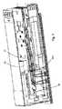
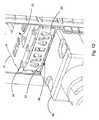
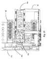
図を参照すると、コネクタアセンブリ10が回路基板5に搭載される。コネクタアセンブリは、ケージ30を含み、プラグアセンブリ90を受容するように構成されるポート12を有する。 Referring to the figure, the
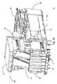
既知のように、プラグアセンブリは、本体92に取り付けられるケーブル93を含み得、示された実施形態は、ラッチシステムがレセプタクルアセンブリ10を解放可能に係合することを可能にするように構成されるラッチ91を含む。プラグアセンブリの代替的な実施形態は、取り付けられたケーブルを有しない本体を含む可能性がある(プラグアセンブリに差し込まれ得る光コネクタを提供する実施形態等)。本体92は、0.65または0.60ピッチでパッドを有し得るパドルカード95を保護し、パドルカード95は、プラグアセンブリ90とレセプタクルアセンブリ10との間のインターフェースの一部である。示された本体92は、ポート12に挿入されるよう意図される本体の長さで実質的に延在し、ある実施形態においては、突起60の前面60aを過ぎる端92aまで上面に沿って延在する、冷却溝96を含む表面94を含む。冷却溝96は、プラグアセンブリ90がポート12に挿入されるときに、空気がポート12を通って流れることを可能にし、気流がプラグアセンブリ90を直接冷却することができるため、先行技術の設計と比べて冷却効率を実質的に向上させる。 As is known, the plug assembly may include a
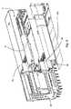
レセプタクルアセンブリ10は、上壁31a、2つの側壁31b、および後壁31cを含む。遮蔽性能を向上するために、底壁31dも提供され得る。ハウジング50は、ケージ内に位置付けられ、ウェハアレイ40を支持する。ハウジング50は、突起60を含み、カードスロット62は、突起60内に提供される。カードスロット62は、パドルカード95と係合し、パドルカード95をカードスロット62の片側へ付勢するように構成される付勢要素68を含む。これは、カードスロットと相対したパドルカード95の制御を可能にし、さもなければパドルカード95上のパッドの位置対カードスロット62内に提供される接触部の位置と関連していたであろう様々な公差を除去する。絶縁性樹脂で形成され得るハウジング50は、さらなる冷却を可能にする空気流路52をさらに含み、ハウジング50にスナップ留めされ、ウェハアレイ40を適所に固定するのに役立つ背面支持54を有し得る。 The
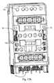
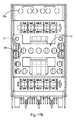
既知のように、ウェハアレイ40は、複数のウェハ41を含み、各ウェハ41は、それぞれ尾部42および接触部44を有し得る複数の端子を支持する。接触部44は、カードスロット62に位置付けられ、典型的には、いくつかの接触部が、カードスロット62の対向側に位置付けられるように配置される。性能を向上させるために、短リブ67は、差動対45を形成する信号端子を分離させ、一方で、長リブは、信号端子と対応する接地端子との間に位置付けられる。接触部44は、一定のピッチで単一の列で位置付けられるため、短リブ67は、電気的分離および信号端子間の保護を提供し、一方で、長リブ65は、信号端子と関連する誘電率と比べて信号端子と接地端子との間の誘電接触を増加させて、差動対間の優先結合を提供する(例えば、端子が一定のピッチであるとしても、対称性により示唆されるよりも多くのエネルギーが差動結合に運ばれる)。言い換えると、リブ65、67は、接触部44を保護するのに役立つ溝を形成し、信号端子は、信号端子接触部の近くの誘電率を下げるのに役立つカードスロット62内に形成されるノッチ69と整列する。 As is known, the
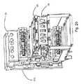
ケージは、前部32を含み、これはケージ30の残りに対する構造支持を提供し得、底壁31dから延在する肩部38を含み得るこの前部32は、ポート内に位置付けられ得かつEMI放射を最小化するのに役立つ、EMIガスケット32aを支持し得る。光パイプ29が提供され得(それらは、透明であることが多いため、図のように透明であるように示される)、典型的には、支持回路基板から前面11aに向かって、通常は2つのポート間に、光を方向付けるよう構成されるであろう。 The cage includes a
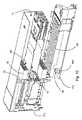
ポート12を画定するのに役立つように、中央支持21が提供される。中央支持21は、側面31bによって支持され、それぞれポートの底部または上部を画定するのに役立つ上壁21aおよび底壁21bで形成され得る。中央ダクト26は、中央支持21によって画定される。上壁および底壁21a、21bは、ノッチ23を含んで、気流がポート12内に流れることをさらに可能にし得る。挿入部15は、中央支持21内に位置付けられる。挿入部15は、空気が前壁16を通って流れることを可能にする前開口部16aを有する前壁16を含み、さらに、光パイプを用いるインジケータが対応する領域を照射することを可能にする。 A
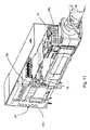
コネクタアセンブリはまた、中間開口部72aを有する中間アレイ72を有する中間壁70を含み、さらに、上部ポート12内に位置付けられる開口部72bを含み、底部ポート12内に位置付けられる開口部72cを含む。開口部72a、72b、72cは、空気が中間壁70を過ぎて流れることを可能にし、一方で、依然として、望ましいEMI保護を提供する。中間壁70は、光パイプ29が中間壁70を過ぎて延在することを可能にする切り抜き73を有する。したがって、示された設計は、光パイプの使用を可能にし、一方で、依然として、向上した冷却能力を提供する。 The connector assembly also includes an
後開口部34aは、空気が後壁31cを過ぎて流れることを可能にする。ハウジング50は、空気が中間壁70を過ぎてそこから後壁31cへ流れ得るように、ハウジング50の側面に十分な空間があるように設計される。したがって、理解され得るように、コネクタアセンブリ10は、相当な気流が、前面11aから後面11b(または反対方向)へ通ることを可能にするように構成される。具体的には、空気が前面11aから後面11bへ流れる場合、挿入部15は、空気が前壁16を通って流れることを可能にするように構成され、空気は、中央ダクト26を通り、その後、中間壁70を通り、ハウジング50を過ぎて、最終的に後壁31cから流れ出る。 The
理解され得るように、0.60または0.65mmピッチで端子を提供する示された実施形態において、カードスロットが開示される。必要な公差を提供するために、付勢要素68がカードスロット内に提供され、付勢要素68は、パドルカードの片側の位置が分かる(片側が、カードスロットの片側に対して付勢される)ことを確実にするのに役立つ。これは、従来のパドルカードベースの嵌合コネクタを用いて0.6mmピッチコネクタが可能であるように、公差累積を低減させる。これは、プラグコネクタ90内のパドルカード95の位置の公差累積の可能性があることが判明しているため、先行技術の設計と比べて、プラグコネクタ全体を付勢させることに対するさらなる向上を提供する。しかしながら、示された実施形態は、パドルカード95のエッジ95aとしての公差累積の形が基準となることを排除する。パドルカード95のエッジ95aが、パドルカード95に位置付けられるパッド97を整列するために用いられる場合、公差はさらに向上し得る。そうでなければ、パドルカードを形成するために用いられる標準的な構成技術は、0.6mmピッチ端子が信頼できる様式で機能することを妨げる公差累積をもたらすであろう。 As can be appreciated, in the illustrated embodiment of providing terminals at a 0.60 or 0.65 mm pitch, a card slot is disclosed. To provide the necessary tolerances, a biasing
端子がより大きいピッチ(0.7以上等)である場合、付勢要素は省略され得ることに留意すべできある。コネクタ設計は、依然として、小型パッケージに対して望ましい冷却特性を提供し、冷却特徴は、端子のピッチにかかわらず、コネクタに組み入れられ得る。 It should be noted that the biasing elements may be omitted if the terminals are at a larger pitch (such as 0.7 or more). The connector design still provides desirable cooling characteristics for small packages, and the cooling features can be incorporated into the connector regardless of the terminal pitch.
ケーブルアセンブリは、全ての状況において冷却溝を提供する必要はない。例えば、ケーブルアセンブリが受動デバイスである場合、冷却の必要性は殆どなく、冷却溝は省略され得る。 The cable assembly need not provide a cooling groove in all situations. For example, if the cable assembly is a passive device, there is little need for cooling and the cooling groove can be omitted.
本明細書に提供される開示は、その好ましく、例示的な実施形態の点から特徴を説明する。本開示を再検討することにより、当業者には、添付の特許請求の範囲および趣旨内の多くの他の実施形態、修正形態、および変形形態が想起されるであろう。 The disclosure provided herein describes its features in terms of its preferred and exemplary embodiments. Upon review of this disclosure, those skilled in the art will envision many other embodiments, modifications, and variations that fall within the scope and spirit of the claims appended hereto.
Claims (14)
Translated fromJapanese該ケージ内に位置付けられるハウジングであって、前記第1のポートと整列する第1のカードスロットおよび前記第2のポートと整列する第2のカードスロットを有する、ハウジングと、を備え、
前記ケージおよびハウジングは、空気が前面から後壁へ流れることを可能にするように構成され、空気は、前記中央ダクトを通過する、コネクタシステムであって、
本体およびパドルカードを含むプラグアセンブリであって、前記本体に第1の表面を含み、該第1の表面は、プラグアセンブリが前記第1または第2のポート内に位置付けられている間に、空気が前記ポートを通って流れることを可能にするように構成される複数の冷却溝を含む、プラグアセンブリを更に備える、コネクタシステム。A cage comprising front and rear surfaces and first and second ports and a central duct between the two ports;
A housing positioned within the cage, the housing having a first card slot aligned with the first port and a second card slot aligned with the second port;
The cage and housing are configured to allow air to flow from the front to the rear wall, the air passing through the central duct, a connector system,
A plug assembly including a body and a paddle card, wherein the body includes a first surface, the first surface being an air vent while the plug assembly is positioned in the first or second port. The connector system further comprising a plug assembly that includes a plurality of cooling grooves configured to allow flow through the port.
上面および底面を有するハウジングであって、熱伝導性材料で形成されるハウジングと、
該ハウジング内に位置付けられるパドルカードであって、プラグコネクタの前端に向かって延在するパドルカードと、を備え、
前記上面および底面のうちの1つは、プラグコネクタの長さ方向に沿って前記上面上または底面上に延在する複数の溝を有する、プラグコネクタ。A plug connector,
A housing having a top surface and a bottom surface, the housing formed of a thermally conductive material;
A paddle card positioned within the housing, the paddle card extending toward a front end of the plug connector;
One of the top surface and the bottom surface is a plug connector having a plurality of grooves extending on the top surface or the bottom surface along a length direction of the plug connector.
前記ポート内に位置付けられるプラグアセンブリであって、該プラグアセンブリは、本体および前記接触部と係合するパッドを有するパドルカードを含み、該パドルカードは、前記カードスロットの第2の側に押し付けられるエッジを有し、前記第1の側は、前記第2の側の反対側にあり、前記本体に第1の表面を含み、該第1の表面は、プラグアセンブリが前記ポート内に位置付けられている間に、空気が前記ポートを通って流れることを可能にするように構成される複数の冷却溝を含む、プラグアセンブリと、を備える、コネクタアセンブリ。A receptacle having a cage defining a port and a housing positioned within the cage, the cage having a rear wall, the housing having a card slot aligned with the port, the card slot comprising: A plurality of terminals having contact portions positioned in the card slot, the contact portions forming a row and having a pitch of 0.59 mm to 0.66 mm; A receptacle having a biasing element positioned on one side;
A plug assembly positioned within the port, the plug assembly including a paddle card having a body and a pad that engages the contact portion, the paddle card being pressed against a second side of the card slot. has an edge, the first side is on the opposite side of the second side includes a first surface on the body, the first surface, the plug assembly beforeKipo over the preparative A plug assembly comprising a plurality of cooling grooves configured to allow air to flow through the port while positioned.
Applications Claiming Priority (3)
| Application Number | Priority Date | Filing Date | Title |
|---|---|---|---|
| US201461971366P | 2014-03-27 | 2014-03-27 | |
| US61/971,366 | 2014-03-27 | ||
| PCT/US2015/022705WO2015148786A1 (en) | 2014-03-27 | 2015-03-26 | Thermally efficient connector system |
Publications (2)
| Publication Number | Publication Date |
|---|---|
| JP2017510031A JP2017510031A (en) | 2017-04-06 |
| JP6479840B2true JP6479840B2 (en) | 2019-03-06 |
Family
ID=54196389
Family Applications (1)
| Application Number | Title | Priority Date | Filing Date |
|---|---|---|---|
| JP2016554266AActiveJP6479840B2 (en) | 2014-03-27 | 2015-03-26 | Thermally efficient connector system |
Country Status (6)
| Country | Link |
|---|---|
| US (3) | US9960553B2 (en) |
| EP (1) | EP3123572B1 (en) |
| JP (1) | JP6479840B2 (en) |
| CN (2) | CN106936034B (en) |
| TW (2) | TWI584533B (en) |
| WO (1) | WO2015148786A1 (en) |
Families Citing this family (39)
| Publication number | Priority date | Publication date | Assignee | Title |
|---|---|---|---|---|
| JP6479840B2 (en)* | 2014-03-27 | 2019-03-06 | モレックス エルエルシー | Thermally efficient connector system |
| CN110632717A (en)* | 2015-09-10 | 2019-12-31 | 申泰公司 | Rack mount equipment with high heat dissipation modules and transceiver sockets with increased cooling |
| US10164362B2 (en) | 2015-12-31 | 2018-12-25 | Foxconn Interconnect Technology Limited | Plug connecetor with a metallic enclosure having heat sink member thereon |
| US9666997B1 (en)* | 2016-03-14 | 2017-05-30 | Te Connectivity Corporation | Gasket plate for a receptacle assembly of a communication system |
| US9825408B2 (en)* | 2016-03-14 | 2017-11-21 | Te Connectivity Corporation | Connector module assembly having a gasket plate |
| US11309655B2 (en) | 2016-05-16 | 2022-04-19 | Molex, Llc | High density receptacle |
| DE102016225642A1 (en)* | 2016-11-23 | 2018-05-24 | Md Elektronik Gmbh | Electrical connector for a multi-core electrical cable |
| CN107046206B (en)* | 2017-01-23 | 2021-07-20 | 富士康(昆山)电脑接插件有限公司 | Electrical connector |
| FR3063838A1 (en)* | 2017-03-10 | 2018-09-14 | Radiall | CONNECTION ASSEMBLY OF A PLUG TO AN ELECTRONIC EQUIPMENT BOARD PANEL BASE, INTEGRATING A THERMAL REGULATION MEANS, PLUG AND SAME THEREFOR |
| WO2018226805A1 (en)* | 2017-06-07 | 2018-12-13 | Samtec, Inc. | Transceiver assembly array with fixed heatsink and floating transceivers |
| US11088480B2 (en)* | 2017-06-13 | 2021-08-10 | Molex, Llc | High density receptacle |
| US10644472B2 (en)* | 2017-06-28 | 2020-05-05 | Mellanox Technologies, Ltd. | Cable adapter |
| US10381761B2 (en)* | 2017-07-21 | 2019-08-13 | Quanta Computer Inc. | Add-on processing unit with I/O connectors |
| US20190068768A1 (en)* | 2017-08-31 | 2019-02-28 | Rohan Garg | Privacy protection system |
| EP3618202B1 (en)* | 2017-10-11 | 2023-12-06 | Guangdong Gopod Group Co., Ltd. | Connector converter |
| JP7066843B2 (en) | 2017-11-21 | 2022-05-13 | モレックス エルエルシー | Keyed I/O Connectors |
| CN109980400B (en)* | 2017-12-28 | 2021-07-23 | 泰科电子(上海)有限公司 | Connector |
| WO2019139882A1 (en)* | 2018-01-09 | 2019-07-18 | Molex, Llc | High density receptacle |
| US10705309B2 (en) | 2018-06-06 | 2020-07-07 | Mellanox Technologies, Ltd. | RF EMI reducing fiber cable assembly |
| US10506737B1 (en)* | 2018-12-17 | 2019-12-10 | Te Connectivity Corporation | Airflow fairings for circuit card assemblies of a communication system |
| CN111416239A (en)* | 2019-01-08 | 2020-07-14 | 泰科电子(上海)有限公司 | Leadframes, Electrical Equipment and Isolation Components |
| US10741954B1 (en) | 2019-03-17 | 2020-08-11 | Mellanox Technologies, Ltd. | Multi-form-factor connector |
| US10873161B2 (en)* | 2019-05-06 | 2020-12-22 | Te Connectivity Corporation | Receptacle assembly having cabled receptacle connector |
| DE102019111749B4 (en) | 2019-05-07 | 2025-06-12 | Te Connectivity Germany Gmbh | Electrical connector and electrical entity |
| CN114424411A (en) | 2019-10-09 | 2022-04-29 | 山一电机株式会社 | Connector for photoelectric conversion module and connector assembly for photoelectric conversion module |
| US11169330B2 (en) | 2019-10-24 | 2021-11-09 | Mellanox Technologies Tlv Ltd. | Wavelength-splitting optical cable |
| US11011861B1 (en)* | 2019-10-25 | 2021-05-18 | TE Connectivity Services Gmbh | Stacked receptacle connector assembly |
| CN111883962B (en)* | 2020-07-03 | 2025-02-28 | 东莞立讯技术有限公司 | Electrical connector component and electrical connector assembly |
| EP4214081A4 (en) | 2020-09-18 | 2024-10-02 | Nubis Communications, Inc. | DATA PROCESSING SYSTEMS INCLUDING OPTICAL COMMUNICATION MODULES |
| US11988874B2 (en) | 2020-10-07 | 2024-05-21 | Nubis Communications, Inc. | Data processing systems including optical communication modules |
| US11327257B1 (en)* | 2020-10-22 | 2022-05-10 | Mellanox Technologies, Ltd. | Networking communication adapter |
| US11650385B2 (en)* | 2021-02-03 | 2023-05-16 | Cisco Technology, Inc. | Optical module cages mounted for optimal density and cooling |
| US12066653B2 (en) | 2021-04-22 | 2024-08-20 | Nubis Communications, Inc. | Communication systems having optical power supplies |
| EP4356175A4 (en) | 2021-06-17 | 2025-07-16 | Nubis Communications Inc | COMMUNICATION SYSTEMS WITH PLUG-IN MODULES |
| US12250024B2 (en) | 2021-09-16 | 2025-03-11 | Nubis Communications, Inc. | Data processing systems including optical communication modules |
| EP4152065A1 (en) | 2021-09-16 | 2023-03-22 | Nubis Communications, Inc. | Communication systems having co-packaged optical modules |
| US12248190B2 (en)* | 2021-12-12 | 2025-03-11 | Molex, Llc | Biased connector system |
| US11855381B2 (en)* | 2022-02-16 | 2023-12-26 | Hewlett Packard Enterprise Development Lp | Chassis having an insertion key assembly for a pluggable module |
| EP4519728A1 (en) | 2022-05-02 | 2025-03-12 | Nubis Communications, Inc. | Communication systems having pluggable optical modules |
Family Cites Families (68)
| Publication number | Priority date | Publication date | Assignee | Title |
|---|---|---|---|---|
| US5767999A (en)* | 1996-05-02 | 1998-06-16 | Vixel Corporation | Hot-pluggable/interchangeable circuit module and universal guide system having a standard form factor |
| JPH10189178A (en) | 1996-12-26 | 1998-07-21 | Dai Ichi Denshi Kogyo Kk | Electric connector |
| US6062893A (en)* | 1998-06-04 | 2000-05-16 | Molex Incorporated | Adapter frame for an electrical connector |
| US6585534B2 (en)* | 1998-08-20 | 2003-07-01 | Intel Corporation | Retention mechanism for an electrical assembly |
| US6178096B1 (en)* | 1998-11-25 | 2001-01-23 | The Whitaker Corporation | Shielding cover having parts held together by latch members |
| US7013088B1 (en)* | 1999-05-26 | 2006-03-14 | Jds Uniphase Corporation | Method and apparatus for parallel optical interconnection of fiber optic transmitters, receivers and transceivers |
| US6431765B1 (en)* | 1999-06-11 | 2002-08-13 | Cisco Technology Inc. | Distributed network repeater module and method |
| JP2001118629A (en)* | 1999-10-18 | 2001-04-27 | Jst Mfg Co Ltd | Connector and cooling method for electronic module mounted on connector |
| US7314318B2 (en)* | 2001-03-15 | 2008-01-01 | International Business Machines Corporation | Compact optical transceivers including thermal distributing and electromagnetic shielding systems and methods thereof |
| GB2373374B (en)* | 2001-03-15 | 2004-03-17 | Agilent Technologies Inc | Novel fiber optic transceiver module |
| TW514327U (en)* | 2001-06-06 | 2002-12-11 | Hon Hai Prec Ind Co Ltd | Photoelectric signal converter |
| US6600865B2 (en)* | 2001-06-21 | 2003-07-29 | Hon Hai Precision Ind. Co., Ltd. | Stacked GBIC guide rail assembly |
| TW582559U (en)* | 2001-10-17 | 2004-04-01 | Hon Hai Prec Ind Co Ltd | Optical transceiver |
| EP1343037B1 (en)* | 2002-03-05 | 2003-12-17 | Agilent Technologies, Inc. (a Delaware corporation) | Opto-electronical module with EMI-shielding |
| AU2003220045A1 (en)* | 2002-03-06 | 2003-09-22 | Tyco Electronics Corporation | Receptacle assembly having shielded interface with pluggable electronic module |
| US7371965B2 (en)* | 2002-05-09 | 2008-05-13 | Finisar Corporation | Modular cage with heat sink for use with pluggable module |
| US6870746B2 (en)* | 2002-11-06 | 2005-03-22 | Agilent Technologies, Inc. | Electronic module |
| US6975510B1 (en)* | 2003-05-09 | 2005-12-13 | Linux Networx | Ventilated housing for electronic components |
| US7066762B2 (en)* | 2003-06-27 | 2006-06-27 | Molex Incorporated | Adapter module retention latches |
| GB2405264B (en)* | 2003-08-20 | 2007-02-28 | Agilent Technologies Inc | Pluggable optical subassembly |
| US7070446B2 (en)* | 2003-08-27 | 2006-07-04 | Tyco Electronics Corporation | Stacked SFP connector and cage assembly |
| US7023703B2 (en)* | 2003-10-20 | 2006-04-04 | Molex Incorporated | Module retention latch assembly |
| JP4026605B2 (en)* | 2004-03-01 | 2007-12-26 | 松下電工株式会社 | Manufacturing method of connector for electric wire connection |
| JP2005316475A (en)* | 2004-04-29 | 2005-11-10 | Sumitomo Electric Ind Ltd | Optical transceiver |
| US7357673B2 (en)* | 2004-06-30 | 2008-04-15 | Molex Incorporated | Shielded cage assembly for electrical connectors |
| US7281862B2 (en)* | 2005-03-31 | 2007-10-16 | Intel Corporation | Optical device latching mechanism |
| TWI276857B (en)* | 2005-06-10 | 2007-03-21 | Delta Electronics Inc | A connecting module for communication |
| JP4517998B2 (en)* | 2005-10-07 | 2010-08-04 | パナソニック電工株式会社 | Memory card socket |
| WO2007058031A1 (en)* | 2005-11-15 | 2007-05-24 | Matsushita Electric Works, Ltd. | Connector for small recording medium |
| JP4730092B2 (en)* | 2005-12-28 | 2011-07-20 | 日立電線株式会社 | Latch mechanism and electronic module with latch mechanism |
| US7804696B2 (en)* | 2006-12-07 | 2010-09-28 | Finisar Corporation | Electromagnetic radiation containment in an electronic module |
| US7547149B2 (en)* | 2006-12-19 | 2009-06-16 | Finisar Corporation | Optical connector latch assembly for an optoelectronic module |
| US7543995B2 (en)* | 2006-12-19 | 2009-06-09 | Finisar Corporation | Optical subassembly connector block for an optoelectronic module |
| US7646615B2 (en)* | 2006-12-19 | 2010-01-12 | Finisar Corporation | Electromagnetic inferference shield for an optoelectronic module |
| US7484987B2 (en)* | 2006-12-19 | 2009-02-03 | Finisar Corporation | Latch assembly for an optoelectronic module |
| US7845975B2 (en)* | 2007-01-30 | 2010-12-07 | Pulse Engineering, Inc. | Low-profile connector assembly and methods |
| US7597573B2 (en) | 2007-02-26 | 2009-10-06 | Tyco Electronics Corporation | Low profile high current power connector with cooling slots |
| US7764504B2 (en)* | 2007-05-16 | 2010-07-27 | Tyco Electronics Corporation | Heat transfer system for a receptacle assembly |
| US7914317B2 (en)* | 2007-08-24 | 2011-03-29 | Methode Electronics, Inc. | Reverse cam release mechanism |
| JP4915342B2 (en)* | 2007-12-21 | 2012-04-11 | 住友電気工業株式会社 | Optical transceiver heat dissipation device |
| US8684765B2 (en) | 2008-10-31 | 2014-04-01 | Tyco Electronics Corporation | Connector assembly including a light pipe assembly |
| MY155071A (en)* | 2008-12-12 | 2015-08-28 | Molex Inc | Resonance modifying connector |
| US7704097B1 (en)* | 2009-02-17 | 2010-04-27 | Tyco Electronics Corporation | Connector assembly having an electromagnetic seal element |
| WO2010104847A1 (en)* | 2009-03-10 | 2010-09-16 | Molex Incorporated | Connector assembly with improved cooling capability |
| US8535787B1 (en)* | 2009-06-29 | 2013-09-17 | Juniper Networks, Inc. | Heat sinks having a thermal interface for cooling electronic devices |
| US8035973B2 (en)* | 2009-08-31 | 2011-10-11 | Avago Technologies Fiber Ip (Singapore) Pte. Ltd. | Cage having a heat sink device secured thereto in a floating arrangement that ensures that continuous contact is maintained between the heat sink device and a parallel optical communications device secured to the cage |
| US7896659B1 (en)* | 2009-09-08 | 2011-03-01 | Tyco Electronics Corporation | Modular connector system |
| US8534930B1 (en)* | 2009-09-24 | 2013-09-17 | Juniper Networks, Inc. | Circuit boards defining openings for cooling electronic devices |
| CN102906947B (en)* | 2009-11-13 | 2016-04-13 | 安费诺有限公司 | The connector controlled with normal mode reactance of high-performance, small-shape factor |
| JP5418187B2 (en) | 2009-12-02 | 2014-02-19 | ソニー株式会社 | Contact operation determination device, contact operation determination method, and program |
| US8345426B2 (en)* | 2010-08-16 | 2013-01-01 | Tyco Electronics Corporation | Guide system for a card module |
| US8038466B1 (en) | 2010-09-13 | 2011-10-18 | Alltop Electronics (Suzhou) Co., Ltd | Power receptacle with enlarged heat dissipation path formed on mating face and power connector assembly thereof |
| CN102403602B (en)* | 2010-09-13 | 2014-05-14 | 凡甲电子(苏州)有限公司 | Socket power supply connector, plug power supply connector and component of socket power supply connector and plug power supply connector |
| US8277252B2 (en)* | 2010-10-01 | 2012-10-02 | Tyco Electronics Corporation | Electrical connector assembly |
| US8545268B2 (en)* | 2010-10-01 | 2013-10-01 | Tyco Electronics Corporation | Electrical connector assembly |
| US8545267B2 (en)* | 2010-10-01 | 2013-10-01 | Tyco Electronics Corporation | Electrical connector assembly |
| US8393917B2 (en)* | 2010-10-25 | 2013-03-12 | Molex Incorporated | Connector system with airflow control |
| CN102544796B (en) | 2010-12-28 | 2014-06-18 | 凡甲电子(苏州)有限公司 | Card edge connector and assembly thereof |
| JP5083426B2 (en) | 2011-03-14 | 2012-11-28 | オムロン株式会社 | Terminal and connector using the same |
| US9419403B2 (en)* | 2011-07-01 | 2016-08-16 | Samtec, Inc. | Transceiver system |
| US9052483B2 (en)* | 2011-09-27 | 2015-06-09 | Finisar Corporation | Communication module assembly with heat sink and methods of manufacture |
| US20130157499A1 (en)* | 2011-12-20 | 2013-06-20 | International Business Machines Corporation | Active electrical connection with self-engaging, self-releasing heat-sink |
| US8613632B1 (en)* | 2012-06-20 | 2013-12-24 | Tyco Electronics Corporation | Electrical connector assembly having thermal vents |
| US8834205B2 (en)* | 2012-07-19 | 2014-09-16 | Tyco Electronics Corporation | Pluggable module system |
| EP2989691B1 (en)* | 2013-04-24 | 2024-07-24 | Molex, LLC | Connector system with thermal surface |
| US9518785B2 (en)* | 2013-07-24 | 2016-12-13 | Tyco Electronics Corporation | Receptacle assembly for receiving a pluggable module |
| JP6479840B2 (en)* | 2014-03-27 | 2019-03-06 | モレックス エルエルシー | Thermally efficient connector system |
| US9391407B1 (en)* | 2015-06-12 | 2016-07-12 | Tyco Electronics Corporation | Electrical connector assembly having stepped surface |
- 2015
- 2015-03-26JPJP2016554266Apatent/JP6479840B2/enactiveActive
- 2015-03-26USUS15/109,862patent/US9960553B2/enactiveActive
- 2015-03-26CNCN201710174054.3Apatent/CN106936034B/enactiveActive
- 2015-03-26EPEP15768390.5Apatent/EP3123572B1/enactiveActive
- 2015-03-26WOPCT/US2015/022705patent/WO2015148786A1/enactiveApplication Filing
- 2015-03-26CNCN201580014642.XApatent/CN106134013B/enactiveActive
- 2015-03-27TWTW104110022Apatent/TWI584533B/enactive
- 2015-03-27TWTW106110439Apatent/TWI675513B/enactive
- 2018
- 2018-04-30USUS15/966,141patent/US10374372B2/enactiveActive
- 2019
- 2019-08-05USUS16/531,725patent/US10797451B2/enactiveActive
Also Published As
| Publication number | Publication date |
|---|---|
| TWI584533B (en) | 2017-05-21 |
| US20190356093A1 (en) | 2019-11-21 |
| CN106936034A (en) | 2017-07-07 |
| EP3123572A4 (en) | 2017-12-20 |
| CN106134013A (en) | 2016-11-16 |
| US9960553B2 (en) | 2018-05-01 |
| EP3123572A1 (en) | 2017-02-01 |
| US20170005446A1 (en) | 2017-01-05 |
| WO2015148786A1 (en) | 2015-10-01 |
| US10797451B2 (en) | 2020-10-06 |
| CN106936034B (en) | 2019-06-07 |
| TW201607160A (en) | 2016-02-16 |
| US20180248324A1 (en) | 2018-08-30 |
| CN106134013B (en) | 2019-05-07 |
| JP2017510031A (en) | 2017-04-06 |
| EP3123572B1 (en) | 2022-07-20 |
| US10374372B2 (en) | 2019-08-06 |
| TWI675513B (en) | 2019-10-21 |
| TW201740626A (en) | 2017-11-16 |
Similar Documents
| Publication | Publication Date | Title |
|---|---|---|
| JP6479840B2 (en) | Thermally efficient connector system | |
| US10895703B2 (en) | Connector system with air flow and flanges | |
| US10403993B2 (en) | Connector system with thermal surface | |
| US11165185B2 (en) | Electrical connector heat sink with protective ramp | |
| US9960525B2 (en) | Connector with integrated heat sink | |
| CN108140985B (en) | Two-row plug and socket assemblies | |
| JP6374011B2 (en) | Thermal vent connector | |
| US20170373418A1 (en) | Connector with thermal management | |
| JP2022060193A (en) | High Density Receptacle |
Legal Events
| Date | Code | Title | Description |
|---|---|---|---|
| A521 | Request for written amendment filed | Free format text:JAPANESE INTERMEDIATE CODE: A523 Effective date:20160825 | |
| A621 | Written request for application examination | Free format text:JAPANESE INTERMEDIATE CODE: A621 Effective date:20160825 | |
| A977 | Report on retrieval | Free format text:JAPANESE INTERMEDIATE CODE: A971007 Effective date:20170706 | |
| A131 | Notification of reasons for refusal | Free format text:JAPANESE INTERMEDIATE CODE: A131 Effective date:20170725 | |
| A601 | Written request for extension of time | Free format text:JAPANESE INTERMEDIATE CODE: A601 Effective date:20171024 | |
| A601 | Written request for extension of time | Free format text:JAPANESE INTERMEDIATE CODE: A601 Effective date:20171222 | |
| A521 | Request for written amendment filed | Free format text:JAPANESE INTERMEDIATE CODE: A523 Effective date:20180124 | |
| A131 | Notification of reasons for refusal | Free format text:JAPANESE INTERMEDIATE CODE: A131 Effective date:20180522 | |
| A521 | Request for written amendment filed | Free format text:JAPANESE INTERMEDIATE CODE: A523 Effective date:20180731 | |
| TRDD | Decision of grant or rejection written | ||
| A01 | Written decision to grant a patent or to grant a registration (utility model) | Free format text:JAPANESE INTERMEDIATE CODE: A01 Effective date:20190108 | |
| A61 | First payment of annual fees (during grant procedure) | Free format text:JAPANESE INTERMEDIATE CODE: A61 Effective date:20190206 | |
| R150 | Certificate of patent or registration of utility model | Ref document number:6479840 Country of ref document:JP Free format text:JAPANESE INTERMEDIATE CODE: R150 | |
| R250 | Receipt of annual fees | Free format text:JAPANESE INTERMEDIATE CODE: R250 | |
| R250 | Receipt of annual fees | Free format text:JAPANESE INTERMEDIATE CODE: R250 | |
| R250 | Receipt of annual fees | Free format text:JAPANESE INTERMEDIATE CODE: R250 | |
| R250 | Receipt of annual fees | Free format text:JAPANESE INTERMEDIATE CODE: R250 |