JP6476853B2 - Network monitoring system and method - Google Patents
Network monitoring system and methodDownload PDFInfo
- Publication number
- JP6476853B2 JP6476853B2JP2014265798AJP2014265798AJP6476853B2JP 6476853 B2JP6476853 B2JP 6476853B2JP 2014265798 AJP2014265798 AJP 2014265798AJP 2014265798 AJP2014265798 AJP 2014265798AJP 6476853 B2JP6476853 B2JP 6476853B2
- Authority
- JP
- Japan
- Prior art keywords
- packet
- packets
- terminal
- network
- information
- Prior art date
- Legal status (The legal status is an assumption and is not a legal conclusion. Google has not performed a legal analysis and makes no representation as to the accuracy of the status listed.)
- Expired - Fee Related
Links
Images


Classifications
- H—ELECTRICITY
- H04—ELECTRIC COMMUNICATION TECHNIQUE
- H04L—TRANSMISSION OF DIGITAL INFORMATION, e.g. TELEGRAPHIC COMMUNICATION
- H04L63/00—Network architectures or network communication protocols for network security
- H04L63/14—Network architectures or network communication protocols for network security for detecting or protecting against malicious traffic
- H04L63/1408—Network architectures or network communication protocols for network security for detecting or protecting against malicious traffic by monitoring network traffic
- H04L63/1416—Event detection, e.g. attack signature detection
- H—ELECTRICITY
- H04—ELECTRIC COMMUNICATION TECHNIQUE
- H04L—TRANSMISSION OF DIGITAL INFORMATION, e.g. TELEGRAPHIC COMMUNICATION
- H04L43/00—Arrangements for monitoring or testing data switching networks
- H04L43/06—Generation of reports
- H04L43/062—Generation of reports related to network traffic
- H—ELECTRICITY
- H04—ELECTRIC COMMUNICATION TECHNIQUE
- H04L—TRANSMISSION OF DIGITAL INFORMATION, e.g. TELEGRAPHIC COMMUNICATION
- H04L43/00—Arrangements for monitoring or testing data switching networks
- H04L43/12—Network monitoring probes
Landscapes
- Engineering & Computer Science (AREA)
- Computer Networks & Wireless Communication (AREA)
- Signal Processing (AREA)
- Computer Security & Cryptography (AREA)
- Computer Hardware Design (AREA)
- Computing Systems (AREA)
- General Engineering & Computer Science (AREA)
- Data Exchanges In Wide-Area Networks (AREA)
- Health & Medical Sciences (AREA)
- Cardiology (AREA)
- General Health & Medical Sciences (AREA)
Description
Translated fromJapanese本発明は、ネットワークの監視技術に関する。 The present invention relates to network monitoring technology.
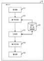
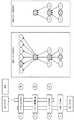
図1に、特定の組織を標的として機密情報を窃取する標的型攻撃の一例を示す。図1の例では、組織内ネットワークの外部にある攻撃者端末が、指令となるパケットAを組織内ネットワークにおける端末(この端末が踏み台である)に送信する。踏み台は、組織内ネットワークにおける他の端末(この端末が標的である)に、遠隔操作型のマルウエアであるRAT(Remote Administration Tool)のプログラム等を含むパケットBを送信し、標的に実行させる。標的は、攻撃者端末との間で新たなコネクションを構築し、標的内の情報等を含むパケットCを攻撃者端末に送信する。あるいは、標的が新たな踏み台として利用され、RATへの感染が広がる。以下では、組織内ネットワークにおいてRATへの感染が広がることをRAT拡散と呼ぶ。 FIG. 1 shows an example of a targeted attack that steals confidential information targeting a specific tissue. In the example of FIG. 1, an attacker terminal outside the in-house network transmits a command packet A to a terminal in the in-house network (this terminal is the springboard). The step sends a packet B including a program of Remote Administration Tool (RAT), which is remote controlled malware, to another terminal in the in-house network (the terminal is a target), and causes the target to execute. The target establishes a new connection with the attacker terminal, and transmits a packet C including information in the target to the attacker terminal. Alternatively, the target is used as a new springboard to spread the infection to the RAT. In the following, the spread of RAT infection in the in-house network is referred to as RAT spreading.
マルウエアを検知する技術として、シグネチャ方式が知られている。シグネチャ方式とは、マルウエア毎に通信データのパターンを定義し、ネットワークを流れる通信データとパターンとの比較によりマルウエアを検知する技術である。しかし、シグネチャ方式では、既にパターンが作成されているマルウエアしか検知することができず、独自に開発されたり、カスタマイズされたマルウエアを検知できない。RAT拡散においては、独自に開発された巧妙なRATが使用されることがあるため、シグネチャ方式では攻撃を検知できない場合がある。 A signature method is known as a technique for detecting malware. The signature method is a technology of defining a pattern of communication data for each malware and detecting malware by comparing the communication data flowing through the network with the pattern. However, the signature method can only detect malware for which a pattern has already been created, and can not detect malware that is originally developed or customized. In RAT spreading, a signature scheme may not be able to detect an attack since a clever RAT developed uniquely may be used.
また、RAT拡散に関係するパケットは通常のパケットに紛れて送信されるため、単一のパケットに基づきRAT拡散であるか否か判別するのは困難である。例えば図1の例においては、パケットA及びパケットCは正常なウェブアクセスのパケットを偽装しているため、個別のパケットを調べただけではRAT拡散であるか否かがわからない。一方で、RAT拡散には複数台の端末が関係するため、RAT拡散に関係するパケットを単一の装置が漏れなく組織内ネットワークから収集するのが難しいという問題がある。 Also, since packets related to RAT spreading are mixed and transmitted as normal packets, it is difficult to determine whether or not RAT spreading is based on a single packet. For example, in the example of FIG. 1, since the packet A and the packet C spoof the packet of normal web access, it is not possible to know whether it is RAT spreading or not only by examining individual packets. On the other hand, since a plurality of terminals are involved in RAT spreading, there is a problem that it is difficult for a single device to collect packets related to RAT spreading from the in-house network without leakage.
さらに、RAT拡散に関係するパケットはネットワークにおいて転送されるパケットのごく一部であるため、単純にネットワーク内の全パケットを収集して検知するような方法を利用すると、処理負荷及び通信負荷が膨大になる。従来技術においては、以上のような問題についての検討が十分ではない。 Furthermore, since packets related to RAT spreading are only a small part of packets transferred in the network, using a method that simply collects and detects all packets in the network will result in a huge processing load and communication load. become. In the prior art, consideration of the above problems is not enough.
従って、本発明の目的は、1つの側面では、RATによる攻撃を適切に検知するための技術を提供することである。 Accordingly, an object of the present invention is, in one aspect, to provide a technique for appropriately detecting an attack by a RAT.
本発明に係るネットワーク監視システムは、第1監視装置と、第2監視装置と、情報処理装置とを有する。そして、上で述べた第1監視装置は、ネットワーク外の装置からネットワーク内の第1端末へのパケットと、第1端末からネットワーク内の第2端末へのパケットとを取得し、取得したパケットのうち第1の条件を満たす第1の複数のパケットの情報を情報処理装置に送信し、第2監視装置は、第1端末から第2端末へのパケットと、第2端末からネットワーク外の装置へのパケットとを取得し、取得したパケットのうち第2の条件を満たす第2の複数のパケットの情報を情報処理装置に送信し、情報処理装置は、第1の複数のパケットの情報及び第2の複数のパケットの情報を受信し、第1の複数のパケットと第2の複数のパケットとに同じパケットが含まれるか否かに基づき、ネットワーク外からの攻撃が発生したか判断する。 A network monitoring system according to the present invention includes a first monitoring device, a second monitoring device, and an information processing device. Then, the first monitoring device described above acquires a packet from a device outside the network to the first terminal in the network and a packet from the first terminal to the second terminal in the network, Information of the first plurality of packets satisfying the first condition is transmitted to the information processing apparatus, and the second monitoring apparatus transmits the packet from the first terminal to the second terminal and the second terminal to the apparatus outside the network Information of the second plurality of packets satisfying the second condition among the acquired packets is transmitted to the information processing apparatus, and the information processing apparatus receives the information of the first plurality of packets and the second information processing apparatus. The information on the plurality of packets is received, and it is determined whether an attack from the outside of the network has occurred based on whether the first plurality of packets and the second plurality of packets include the same packet.
1つの側面では、RATによる攻撃を適切に検知できるようになる。 In one aspect, RAT attacks can be properly detected.
[実施の形態1]
図2に、本実施の形態のシステム概要を示す。例えばLAN(Local Area Network)である組織内ネットワークには、ユーザ端末51と、ユーザ端末52とが接続される。ユーザ端末51には監視ポイントであるスイッチ11が接続されるので、ユーザ端末51が受信するパケット及びユーザ端末51が送信するパケットはスイッチ11によって監視される。同様に、ユーザ端末52には監視ポイントであるスイッチ21が接続されるので、ユーザ端末52が受信するパケット及びユーザ端末52が送信するパケットはスイッチ21によって監視される。スイッチ11及びスイッチ21はスイッチ70に接続される。スイッチ70はユーザ端末90に接続される。但し、スイッチ70とユーザ端末90との間のネットワークは、インターネット等のWAN(Wide Area Network)を含む場合がある。First Embodiment
FIG. 2 shows an outline of a system according to the present embodiment. For example, a
なお、図1においてはユーザ端末90が攻撃者端末であり、ユーザ端末51が踏み台であり、ユーザ端末52が標的であるが、このような例に限られるわけではない。例えば、ユーザ端末51が標的であり且つユーザ端末52が踏み台になる場合もある。また、図示しない他のユーザ端末が踏み台或いは標的になることもある。 Although in FIG. 1 the
監視装置10はスイッチ11が中継するパケットをミラーリングによってスイッチ11から取得し、取得したパケットから、サーバ30に転送すべきデータを生成する。そして、監視装置10は、生成されたデータをサーバ30を宛先として送信する。同様に、監視装置20はスイッチ21が中継するパケットをミラーリングによってスイッチ21から取得し、取得したパケットから、サーバ30に転送すべきデータを生成する。そして、監視装置20は、生成されたデータをサーバ30を宛先として送信する。スイッチ31は、監視装置10から受信したデータ及び監視装置20から受信したデータをサーバ30に中継する。 The
サーバ30は、監視装置10から受信したデータ及び監視装置20から受信したデータに基づき、RAT拡散を検知する処理を実行する。サーバ30は、RAT拡散を検知した場合、ファイル生成或いはメール送信等によって、組織内ネットワークの管理者にRAT拡散が検知されたことを通知する。 The
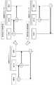
図3に、第1の実施の形態における監視装置10の機能ブロック図を示す。監視装置10は、受信部101と、第1解析部102と、第2解析部103と、抽出部104と、送信部105と、パケットデータ格納部106とを含む。 FIG. 3 shows a functional block diagram of the
受信部101は、スイッチ11が中継するパケットを取得し、取得したパケットに取得時刻の情報を付加して第1解析部102に出力する。第1解析部102は、受信部101から受け取ったパケットから抽出した特徴データに基づき処理を実行し、処理結果である特徴データを第2解析部103に出力する。第2解析部103は、第1解析部102から受け取った特徴データ及びパケットデータ格納部106に格納されたデータに基づき処理を実行し、処理結果を抽出部104に通知する。抽出部104は、第2解析部103から通知された処理結果及びパケットデータ格納部106に格納されたデータに基づき処理を実行し、サーバ30に転送すべきデータを生成する。そして、抽出部104は、生成されたデータを送信部105に出力する。送信部105は、抽出部104から受け取ったデータをサーバ30に送信する。 The
なお、監視装置20の機能ブロック図は監視装置10の機能ブロック図と同じであるので、説明を省略する。 In addition, since the functional block diagram of the
図4に、サーバ30の機能ブロック図を示す。サーバ30は、受信部301と、第1判別部302と、比較部303と、第2判別部304と、通知部305と、前半データ格納部306とを含む。 FIG. 4 shows a functional block diagram of the
受信部301は、監視装置10及び20からデータを受信し、第1判別部302に出力する。第1判別部302は、受信部301から受け取ったデータを前半データ格納部306に格納するか、又は、受信部301から受け取ったデータを比較部303に出力する。比較部303は、第1判別部302から受け取ったデータ及び前半データ格納部306に格納されたデータに基づき処理を実行し、処理結果を第2判別部304に通知する。第2判別部304は、比較部303から通知された処理結果に基づき、RAT拡散を検知し、RAT拡散が検知されたことを通知部305に通知する。通知部305は、第2判別部304からRAT拡散が検知されたことを通知されると、ファイル生成或いはメール送信等によって、組織内ネットワークの管理者にRAT拡散が検知されたことを通知する。 The receiving
図5を用いて、本実施の形態の概要について説明する。本実施の形態においては、組織内ネットワークにおける監視装置10、監視装置20及びサーバ30が連携して動作することでRAT拡散を検知する。例えば、ユーザ端末90が攻撃者端末であり、ユーザ端末51が踏み台であり、ユーザ端末52が標的であるとする。この場合、監視装置10は、ユーザ端末51が受信するパケット及びユーザ端末51が送信するパケットを監視できるので、図1に示したパケットA及びパケットBが出現したことを検知できる。監視装置20は、ユーザ端末52が受信するパケット及びユーザ端末52が送信するパケットを監視できるので、図1に示したパケットB及びパケットCが出現したことを検知できる。このように、複数台の監視装置が連携することによってパケットA乃至Cが出現したことを検知できるようにし、単一の監視装置がRAT拡散に関係するパケットを組織内ネットワークから収集するのが難しいケースに対処できるようにする。 The outline of the present embodiment will be described with reference to FIG. In the present embodiment, the
また、監視装置10はパケットA及びBの情報(以下では、前半データと呼ぶ)をサーバ30に送信し、監視装置20はパケットB及びCの情報(以下では、後半データと呼ぶ)をサーバ30に送信する。サーバ30は、監視装置10から受信した前半データに含まれるパケットBの情報と、監視装置20から受信した後半データに含まれるパケットBの情報とが同じであるか否かに基づき、一連の攻撃パケットが出現したか判断する。従って、サーバ30は組織内ネットワークにおける全パケットを処理せずに済み、監視装置10及び20から送られてきた前半データ及び後半データのみを処理すればよい。これにより、サーバ30の処理負荷を削減することができるようになる。また、サーバ30と監視装置10及び20との間の通信のトラフィックを抑制できる。 Also, the
次に、図6乃至図12を用いて、本実施の形態におけるシステムにおいて行われる処理について説明する。まず、図6乃至図10を用いて、監視装置10が実行する処理について説明する。なお、ここでは監視装置10が実行する処理について説明するが、監視装置20が実行する処理は監視装置10が実行する処理と同様である。 Next, processing performed in the system according to the present embodiment will be described using FIGS. 6 to 12. First, processing executed by the
まず、監視装置10における受信部101は、スイッチ11からミラーリングによってパケットを1つ取得し(図6:ステップS1)、第1解析部102に出力する。 First, the
第1解析部102は、受信部101からパケットを受け取り、特徴データをパケットから抽出し、特徴データに基づき、攻撃パケットである可能性が有るか判断する(ステップS3)。特徴データは、例えば、送信元IP(Internet Protocol)アドレス、宛先IPアドレス、取得時刻、SMB(Server Message Block)ヘッダにおける特定のフィールド値、DCE/RPC(Distributed Computing Environment / Remote Procedure Calls)ヘッダにおける特定のフィールド値、TCP(Transmission Control Protocol)ポート番号、及びTCPシーケンス番号等を含む。但し、ここで例示した全情報を含まなくてもよいし、その他の情報を含んでもよい。 The
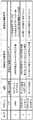
ステップS3における判断は、例えば図7及び8に示す「攻撃性の判断基準」に従って実行される。図7に前半データについての判断基準を示し、図8に後半データについての判断基準を示す。図7及び8においては、パケットのタイプ(種別)を表す番号と、プロトコルと、パケットの役割と、攻撃性の判断基準と、関連性の判断基準とが示されている。タイプ1のパケットは攻撃者端末から踏み台へのパケットであり、タイプ2乃至4のパケットは踏み台から標的へのパケットであり、タイプ5のパケットは標的から攻撃者端末へのパケットである。 The determination in step S3 is performed, for example, in accordance with "criteria for determining aggression" shown in FIGS. FIG. 7 shows the determination criteria for the first half data, and FIG. 8 shows the determination criteria for the second half data. In FIGS. 7 and 8, the number indicating the type (type) of the packet, the protocol, the role of the packet, the aggressiveness determination criterion, and the relevance determination criterion are shown. The
攻撃パケットである可能性が無い場合(ステップS3:Noルート)、第1解析部102はステップS1において取得したパケットを廃棄する。そしてステップS1の処理に戻る。一方、攻撃パケットである可能性が有る場合(ステップS3:Yesルート)、第1解析部102は、ステップS1において取得したパケットの特徴データを第2解析部103に出力する。 If there is no possibility of the attack packet (step S3: No route), the
第2解析部103は、第1解析部102から受け取った特徴データに基づき、ステップS1において取得したパケットに関連するパケットを、パケットデータ格納部106において検索する(ステップS5)。ステップS5における検索は、例えば図7及び8に示した「関連性の判断基準」に従って実行される。 The
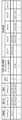
図9に、パケットデータ格納部106に格納されるデータの一例を示す。図9の例では、攻撃者端末(例えばユーザ端末90)のIPアドレスと、踏み台(例えばユーザ端末51)のIPアドレスと、標的(例えばユーザ端末52)のIPアドレスと、次のタイプを表す番号と、比較に使う情報(ここでは、タイプ4のパケットTCPシーケンス番号)と、各タイプのパケットの取得時刻とが格納される。なお、パケットデータ格納部106に格納されたエントリのうち予め定められた時間以上変化しないエントリは削除される。 FIG. 9 shows an example of data stored in the packet
図6の説明に戻り、関連するパケットが有る場合(ステップS7:Yesルート)、第2解析部103は、前半データ又は後半データが完成したか判断する(ステップS9)。前半データはタイプ1乃至4のパケットが揃えば完成であり、後半データはタイプ2乃至5のパケットが揃えば完成である。従って、ステップS1において取得したパケットがタイプ4のパケットであり且つタイプ1乃至4のパケットが揃った場合、前半データが完成する。また、ステップS1において取得したパケットがタイプ5のパケットであり且つタイプ2乃至5のパケットが揃った場合、後半データが完成する。 Returning to the description of FIG. 6, when there is a related packet (step S7: Yes route), the
前半データ又は後半データが完成していない場合(ステップS9:Noルート)、第2解析部103は、特徴データを抽出部104に出力する。そして、抽出部104は、第2解析部103から受け取った特徴データをパケットデータ格納部106に格納する(ステップS15)。そしてステップS1の処理に戻る。ここでは、既に存在するエントリに取得時刻及びIPアドレス等を追加する。そして、抽出部104は、次のタイプを表す番号を1インクリメントする。 When the first half data or the second half data is not completed (step S9: No route), the
前半データ又は後半データが完成した場合(ステップS9:Yesルート)、第2解析部103は、特徴データを抽出部104に出力する。そして、抽出部104は、ステップS1において取得したパケットの特徴データ及びそのパケットに関連するパケットの特徴データを含む前半データ又は後半データを、送信部105に出力する。そして、抽出部104は、完成した前半データ又は後半データについてのエントリをパケットデータ格納部106から削除する。 When the first half data or the second half data is completed (step S9: Yes route), the
図10に、完成した後半データの一例を示す。図10の例では、後半データは、攻撃者端末のIPアドレスと、踏み台のIPアドレスと、標的のIPアドレスと、比較に使う情報と、各タイプのパケットの取得時刻とを含む。なお、前半データも同様のフォーマットであるが、前半データの場合はタイプ1乃至4のパケットについての取得時刻が含まれる。 FIG. 10 shows an example of the completed second half data. In the example of FIG. 10, the second half data includes the IP address of the attacker terminal, the IP address of the platform, the IP address of the target, information used for comparison, and the acquisition time of each type of packet. The first half data has the same format, but in the case of the first half data, the acquisition time for packets of
図6の説明に戻り、送信部105は、抽出部104から受け取った前半データ又は後半データをサーバ30に送信する(ステップS11)。そしてステップS1の処理に戻る。 Returning to the description of FIG. 6, the transmitting
一方、ステップS7において関連するパケットが無いと判断された場合(ステップS7:Noルート)、第2解析部103は、ステップS1において取得したパケットが前半の開始パケット又は後半の開始パケットであるか判断する(ステップS13)。本実施の形態においては、前半の開始パケットはタイプ1のパケットであり、後半の開始パケットはタイプ2のパケットである。 On the other hand, if it is determined in step S7 that there is no related packet (step S7: No route), the
取得したパケットが前半の開始パケット又は後半の開始パケットではない場合(ステップS13:Noルート)、ステップS1の処理に戻る。一方、取得したパケットが前半の開始パケット又は後半の開始パケットである場合(ステップS13:Yesルート)、第2解析部103は、特徴データを抽出部104に出力する。そして、抽出部104は、ステップS1において取得したパケットについてのエントリをパケットデータ格納部106に新たに格納する(ステップS15)。そしてステップS1の処理に戻る。 If the acquired packet is not the start packet of the first half or the start packet of the second half (step S13: No route), the process returns to step S1. On the other hand, when the acquired packet is the start packet of the first half or the start packet of the second half (step S13: Yes route), the
例えば前半の開始パケットである場合、攻撃者端末のIPアドレス、踏み台のIPアドレス、タイプ1のパケットの取得時刻を格納し、次のタイプを表す番号を「2」に設定する。また、例えば後半の開始パケットである場合、踏み台のIPアドレス、攻撃者端末のIPアドレス、タイプ2のパケットの取得時刻を格納し、次のタイプを表す番号を「3」に設定する。For example, in the case of the start packet of the first half, the IP address of the attacker terminal, the IP address of the step board, and the acquisition time of the
以上のような処理を実行すれば、前半データ又は後半データが完成した場合にのみサーバ30との間で通信が発生することになる。これにより、サーバ30と監視装置10及び20との間におけるトラフィックを削減できるようになる。 If the above processing is executed, communication with the
次に、図11及び図12を用いて、サーバ30が実行する処理について説明する。 Next, processing executed by the
まず、サーバ30における受信部301は、監視装置10又は20から、前半データ又は後半データを受信し(図11:ステップS21)、第1判別部302に出力する。 First, the receiving
第1判別部302は、ステップS21において受信したデータが前半データであるか否か判断する(ステップS23)。例えば、受信したデータにタイプ1のパケットの特徴データが含まれる場合、受信したデータは前半データである。また、受信したデータにタイプ5のパケットの特徴データが含まれていない場合、受信したデータは前半データである。 The
受信したデータが前半データである場合(ステップS25:Yesルート)、第1判別部302は、受信した前半データを前半データ格納部306に格納する(ステップS27)。そしてステップS21の処理に戻る。 If the received data is the first half data (step S25: Yes route), the
図12に、前半データ格納部306に格納されるデータの一例を示す。図12の例では、攻撃者端末のIPアドレスと、踏み台のIPアドレスと、標的のIPアドレスと、比較に使う情報(ここでは、タイプ4のパケットのTCPシーケンス番号)と、各タイプのパケットの取得時刻とが格納される。なお、前半データ格納部306に格納されたエントリのうち予め定められた時間以上変化しないエントリは削除される。 An example of data stored in the first half
図11の説明に戻り、ステップS25において受信したデータが前半データではない(すなわち、後半データである)と判断された場合(ステップS25:Noルート)、第1判別部302は、後半データを比較部303に出力する。これに応じ、比較部303は、前半データ格納部306において、後半データに対応する前半データを検索する(ステップS29)。ステップS29においては、後半データに含まれる特徴データと同じ特徴データを含む前半データが検索される。本実施の形態においては、特徴データとしてタイプ4のパケットのTCPシーケンス番号が利用される。但し、タイプ2又は3の特徴データを利用してもよい。また、送信元IPアドレス、宛先IPアドレス、送信元TCPポート番号、宛先TCPポート番号、SMBヘッダにおけるマルチプレクスID及びSMBヘッダにおけるコマンドシーケンス番号をTCPシーケンス番号の代わりに利用してもよいし、それらを組み合わせて利用してもよい。 Returning to the description of FIG. 11, when it is determined that the data received in step S25 is not the first half data (that is, the second half data) (step S25: No route), the
比較部303は、後半データに対応する前半データが有るか判断する(ステップS31)。後半データに対応する前半データが無い場合(ステップS31:Noルート)、ステップS21の処理に戻る。 The
後半データに対応する前半データが有る場合(ステップS31:Yesルート)、比較部303は、後半データ及び前半データを第2判別部304に出力する。これに応じ、第2判別部304は、前半データ及び後半データに基づき、RATによる攻撃であるか否か判断する(ステップS33)。例えば、送信元IPアドレスが、事前に定義されたホワイトリストのIPアドレスに合致する場合には、RATによる攻撃ではないと判断される。また、例えば、タイプ1のパケットの取得時刻とタイプ5のパケットの取得時刻との差が予め定められた時間より長い場合には、RATによる攻撃ではないと判断される。 When there is first half data corresponding to the second half data (step S31: Yes route), the
RATによる攻撃ではないと判断された場合(ステップS35:Noルート)、ステップS21の処理に戻る。RATによる攻撃であると判断された場合(ステップS35:Yesルート)、第2判別部304は、後半データ及び前半データを通知部305に出力する。 If it is determined that the attack is not by the RAT (step S35: No route), the process returns to step S21. If it is determined that the attack is due to the RAT (step S35: Yes route), the
通知部305は、後半データ及び前半データに基づき、RATによる攻撃が発生したことを示すデータを生成して出力する(ステップS37)。ステップS37においては、例えば、データをサーバ30の表示装置に表示したり、メールの文面データを生成してメールを送信する処理が行われる。そしてステップS21の処理に戻る。 The
以上のような処理を実行すれば、2台の監視装置がパケットを収集する場合であっても、RATによる攻撃を適切に検知できるようになる。また、サーバ30は受信した前半データ及び後半データを処理すればよく、組織内ネットワークにおいて転送されるパケットを個別に処理しなくてもよいので、サーバ30の処理負荷を減らせるようになる。 By executing the above-described processing, it is possible to appropriately detect an attack by the RAT even when two monitoring devices collect packets. In addition, the
[実施の形態2]
第2の実施の形態においては、監視装置10及び20の処理負荷を削減する方法について説明する。Second Embodiment
In the second embodiment, a method of reducing the processing load of the
第2の実施の形態における監視装置10及び20は、第1の実施の形態における監視装置10及び20とは異なる。図13に、第2の実施の形態における監視装置10の機能ブロック図を示す。監視装置10は、受信部101と、第1解析部102と、第2解析部103と、抽出部104と、送信部105と、パケットデータ格納部106と、変更部107と、計数部108と、頻度格納部109とを含む。 The
受信部101は、スイッチ11が中継するパケットを取得し、取得したパケットに取得時刻の情報を付加して第1解析部102に出力する。第1解析部102は、受信部101から受け取ったパケットから抽出した特徴データに基づき処理を実行し、処理結果である特徴データを第2解析部103に出力する。第2解析部103は、第1解析部102から受け取った特徴データ及びパケットデータ格納部106に格納されたデータに基づき処理を実行し、処理結果を抽出部104に通知する。抽出部104は、第2解析部103から通知された処理結果及びパケットデータ格納部106に格納されたデータに基づき処理を実行し、後述する前半データ及び後半データを送信部105に出力する。送信部105は、抽出部104から受け取った前半データ及び後半データを、サーバ30に送信する。計数部108は、タイプ毎にパケットの数を計数し、計数の結果に基づき頻度格納部109を更新する。変更部107は、計数部108からの通知に応じて、開始パケットの指定を第2解析部103に出力する。 The receiving
なお、監視装置20の機能ブロック図は監視装置10の機能ブロック図と同じであるので、説明を省略する。 In addition, since the functional block diagram of the
次に、図14乃至図18を用いて、第2の実施の形態における監視装置10が実行する処理について説明する。なお、ここでは監視装置10が実行する処理について説明するが、監視装置20が実行する処理は監視装置10が実行する処理と同様である。 Next, processing executed by the
まず、監視装置10における受信部101は、スイッチ11からミラーリングによってパケットを1つ取得し(図14:ステップS41)、第1解析部102に出力する。 First, the
第1解析部102は、受信部101からパケットを受け取り、特徴データをパケットから抽出し、特徴データに基づき、攻撃パケットである可能性が有るか判断する(ステップS43)。特徴データは、例えば、送信元IP(Internet Protocol)アドレス、宛先IPアドレス、取得時刻、SMB(Server Message Block)ヘッダにおける特定のフィールド値、DCE/RPC(Distributed Computing Environment / Remote Procedure Calls)ヘッダにおける特定のフィールド値、TCP(Transmission Control Protocol)ポート番号、及びTCPシーケンス番号等を含む。但し、ここで例示した全情報を含まなくてもよいし、その他の情報を含んでもよい。 The
ステップS43における判断は、例えば図7及び8に示した「攻撃性の判断基準」に従って実行される。攻撃パケットである可能性が無い場合(ステップS43:Noルート)、第1解析部102はステップS41において取得したパケットを廃棄する。そしてステップS41の処理に戻る。一方、攻撃パケットである可能性が有る場合(ステップS43:Yesルート)、第1解析部102は、ステップS41において取得したパケットの特徴データを第2解析部103に出力する。 The determination in step S43 is performed, for example, in accordance with the "criteria for determining aggression" shown in FIGS. If there is no possibility that the packet is an attack packet (step S43: No route), the
第2解析部103は、第1解析部102から受け取った特徴データに基づき、ステップS41において取得したパケットに関連するパケットを、パケットデータ格納部106において検索する(ステップS45)。ステップS45における検索は、例えば図7及び8に示した「関連性の判断基準」に従って実行される。 The
関連するパケットが有る場合(ステップS47:Yesルート)、第2解析部103は、前半データ又は後半データが完成したか判断する(ステップS49)。前半データはタイプ1乃至4のパケットが揃えば完成であり、後半データはタイプ2乃至5のパケットが揃えば完成である。従って、ステップS41において取得したパケットがタイプ4のパケットであり且つタイプ1乃至4のパケットが揃った場合、前半データが完成する。また、ステップS41において取得したパケットがタイプ5のパケットであり且つタイプ2乃至5のパケットが揃った場合、後半データが完成する。 If there is a related packet (step S47: Yes route), the
前半データ又は後半データが完成していない場合(ステップS49:Noルート)、第2解析部103は、特徴データを抽出部104に出力する。そして、抽出部104は、ステップS43において抽出された特徴データをパケットデータ格納部106に格納する(ステップS55)。ここでは、既に存在するエントリに取得時刻及びIPアドレス等を追加する。そして、抽出部104は、次のタイプを表す番号を1インクリメントする。 When the first half data or the second half data is not completed (step S49: No route), the
前半データ又は後半データが完成した場合(ステップS49:Yesルート)、第2解析部103は、特徴データを抽出部104に出力する。そして、抽出部104は、ステップS41において取得したパケットの特徴データ及びそのパケットに関連するパケットの特徴データを含む前半データ又は後半データを、送信部105に出力する。そして、抽出部104は、完成した前半データ又は後半データについてのエントリをパケットデータ格納部106から削除する。 When the first half data or the second half data is completed (step S49: Yes route), the
送信部105は、抽出部104から受け取った前半データ又は後半データをサーバ30に送信する(ステップS51)。そしてステップS41の処理に戻る。 The transmitting
一方、ステップS47において関連するパケットが無いと判断された場合(ステップS47:Noルート)、第2解析部103は、ステップS41において取得したパケットが前半の開始パケット又は後半の開始パケットであるか判断する(ステップS53)。本実施の形態においては、前半の開始パケットはタイプ1のパケットであり、後半の開始パケットは変更部107により指定されたタイプのパケットである。 On the other hand, when it is determined in step S47 that there is no related packet (step S47: No route), the
取得したパケットが前半の開始パケット又は後半の開始パケットではない場合(ステップS53:Noルート)、ステップS57の処理に移行する。一方、取得したパケットが前半の開始パケット又は後半の開始パケットである場合(ステップS53:Yesルート)、第2解析部103は、特徴データを抽出部104に出力する。そして、抽出部104は、ステップS41において取得したパケットについてのエントリをパケットデータ格納部106に新たに格納する(ステップS55)。 If the acquired packet is not the start packet of the first half or the start packet of the second half (step S53: No route), the process proceeds to step S57. On the other hand, when the acquired packet is the start packet of the first half or the start packet of the second half (step S53: Yes route), the
第2解析部103は、ステップS41において取得したパケットが、後半のパケットのうち前半のパケットと共通のパケットであるか判断する(ステップS57)。図8の例であれば、後半のパケットのうち前半と共通のパケットとは、タイプ2乃至4のパケットである。 The
取得したパケットが後半のパケットのうち前半のパケットと共通のパケットではない場合(ステップS57:Noルート)、ステップS41の処理に戻る。一方、取得したパケットが後半のパケットのうち前半のパケットと共通のパケットである場合(ステップS57:Yesルート)、第2解析部103は、頻度更新指示を計数部108に出力する。これに応じ、計数部108は、頻度格納部109に格納された、ステップS41において取得したパケットのタイプについての頻度を更新する(ステップS59)。 When the acquired packet is not a packet common to the first half packet among the second half packets (step S57: No route), the process returns to step S41. On the other hand, if the acquired packet is a packet common to the first half packet among the second half packets (step S57: Yes route), the
図15に、頻度格納部109に格納されるデータの一例を示す。図15の例では、後半のパケットのうち前半のパケットと共通のパケット(ここでは、タイプ2乃至4のパケット)の各々について、頻度の情報が格納される。頻度は、例えば1秒間あたりのパケットの取得数である。 An example of data stored in the
図14の説明に戻り、計数部108は、現在の開始パケットのタイプの頻度より低頻度であるタイプが有るか判断する(ステップS61)。現在の開始パケットのタイプの頻度より低頻度であるタイプが無い場合(ステップS61:Noルート)、開始パケットを変更すべきではないので、ステップS41の処理に戻る。一方、現在の開始パケットの頻度より低頻度であるタイプが有る場合(ステップS61:Yesルート)、計数部108は、最も頻度が低いタイプを変更部107に通知する。これに応じ、変更部107は、後半の開始パケットを変更する(ステップS63)。具体的には、変更部107は、後半の開始パケットの指定を第2解析部103に出力する。そしてステップS41の処理に戻る。 Returning to the description of FIG. 14, the
図16及び図17を用いて、開始パケットの変更について具体的に説明する。図16の例では、タイプ2の頻度が毎秒80パケットであり、タイプ3の頻度が毎秒12パケットであり、タイプ4の頻度が毎秒20パケットである。この場合、タイプ3のパケットが開始パケットである。タイプ2のパケットは前半でのみ抽出され、後半では抽出されない。そのため、ステップS29における比較部303の処理には利用されない。タイプ3及び4のパケットは比較に利用される可能性がある。 The change of the start packet will be specifically described using FIG. 16 and FIG. In the example of FIG. 16, the frequency of
図17の例では、タイプ2の頻度が毎秒80パケットであり、タイプ3の頻度が毎秒20パケットであり、タイプ4の頻度が毎秒1パケットである。この場合、タイプ4のパケットが開始パケットである。タイプ2及び3のパケットは前半でのみ抽出され、後半では抽出されない。そのため、ステップS29における比較部303の処理には利用されない。タイプ4のパケットの情報のみが比較部303の処理に利用される。 In the example of FIG. 17, the frequency of
以上のような処理を実行すれば、監視装置10及び20の処理負荷を軽減できるようになる。図18を用いて、開始パケットの変更による処理負荷の軽減について説明する。図18の例では、後半のパケットのうち前半のパケットと共通するパケットであるタイプ2のパケット、タイプ3のパケット、及びタイプ4のパケットについて頻度を求めている。ここでは、タイプ2の頻度が最も高く、タイプ3の頻度が最も低く、タイプ4の頻度はタイプ2の頻度より低くタイプ3の頻度より高い。このような状況において後半の開始パケットをタイプ2のパケットに設定すると、タイプ3のパケットと関連するタイプ2のパケットを検索する処理の負荷が多くなる。図18の例であれば、6つのタイプ2のパケットについて関連性を確認することになる。これに対し、後半の開始パケットをタイプ3のパケットに変更すると、タイプ3のパケットと関連するタイプ2のパケットを検索する処理が不要になる。 The processing load on the
なお、第2の実施の形態においては開始パケットが変更される可能性があるため、比較に利用する情報は、開始パケットがいずれであっても取得されるタイプ4のパケットの特徴データであることが好ましい。第1の実施の形態においては開始パケットが変更されないので、タイプ2乃至4のいずれであっても特徴データを比較に利用することができる。 In the second embodiment, since the start packet may be changed, the information used for comparison is the characteristic data of the
以上本発明の一実施の形態を説明したが、本発明はこれに限定されるものではない。例えば、上で説明した監視装置10及び20並びにサーバ30の機能ブロック構成は実際のプログラムモジュール構成に一致しない場合もある。 Although the embodiment of the present invention has been described above, the present invention is not limited to this. For example, the functional block configurations of the
また、上で説明した各データ保持の構成は一例であって、上記のような構成でなければならないわけではない。さらに、処理フローにおいても、処理結果が変わらなければ処理の順番を入れ替えることも可能である。さらに、並列に実行させるようにしても良い。 Further, the configuration of each data holding described above is an example, and the configuration is not necessarily as described above. Furthermore, also in the processing flow, it is possible to change the order of processing as long as the processing result does not change. Furthermore, they may be executed in parallel.
例えば、監視装置10及び20の機能を、組織内ネットワークにおいてパケットを中継する中継装置(例えば、ルータ、スイッチ、或いはファイアウォールなど)がもつようにしてもよい。 For example, the functions of the
また、監視装置10及び20とサーバ30との間のネットワークは、攻撃に関係するネットワークと同一であってもよいし、その他の用途のネットワークであってもよい。また、組織内ネットワークの形態は、図2に示した形態に限られるわけではない。 Also, the network between the
なお、予め行われたテスト運用時の頻度に基づき開始パケットを決定してもよいし、管理者が開始パケットを指定してもよい。 The start packet may be determined based on the frequency of test operation performed in advance, or the administrator may specify the start packet.
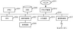
なお、上で述べた監視装置10及び20並びにサーバ30は、コンピュータ装置であって、図19に示すように、メモリ2501とCPU(Central Processing Unit)2503とハードディスク・ドライブ(HDD:Hard Disk Drive)2505と表示装置2509に接続される表示制御部2507とリムーバブル・ディスク2511用のドライブ装置2513と入力装置2515とネットワークに接続するための通信制御部2517とがバス2519で接続されている。オペレーティング・システム(OS:Operating System)及び本実施例における処理を実施するためのアプリケーション・プログラムは、HDD2505に格納されており、CPU2503により実行される際にはHDD2505からメモリ2501に読み出される。CPU2503は、アプリケーション・プログラムの処理内容に応じて表示制御部2507、通信制御部2517、ドライブ装置2513を制御して、所定の動作を行わせる。また、処理途中のデータについては、主としてメモリ2501に格納されるが、HDD2505に格納されるようにしてもよい。本発明の実施例では、上で述べた処理を実施するためのアプリケーション・プログラムはコンピュータ読み取り可能なリムーバブル・ディスク2511に格納されて頒布され、ドライブ装置2513からHDD2505にインストールされる。インターネットなどのネットワーク及び通信制御部2517を経由して、HDD2505にインストールされる場合もある。このようなコンピュータ装置は、上で述べたCPU2503、メモリ2501などのハードウエアとOS及びアプリケーション・プログラムなどのプログラムとが有機的に協働することにより、上で述べたような各種機能を実現する。 The
以上述べた本発明の実施の形態をまとめると、以下のようになる。 The embodiments of the present invention described above are summarized as follows.
本実施の形態に係るネットワーク監視システムは、(A)第1監視装置と、(B)第2監視装置と、(C)情報処理装置とを有する。そして、上で述べた第1監視装置は、(a1)ネットワーク外の装置からネットワーク内の第1端末へのパケットと、第1端末からネットワーク内の第2端末へのパケットとを取得し、取得したパケットのうち第1の条件を満たす第1の複数のパケットの情報を情報処理装置に送信し、第2監視装置は、(b1)第1端末から第2端末へのパケットと、第2端末からネットワーク外の装置へのパケットとを取得し、取得したパケットのうち第2の条件を満たす第2の複数のパケットの情報を情報処理装置に送信し、情報処理装置は、(c1)第1の複数のパケットの情報及び第2の複数のパケットの情報を受信し、第1の複数のパケットと第2の複数のパケットとに同じパケットが含まれるか否かに基づき、ネットワーク外からの攻撃が発生したか判断する。 The network monitoring system according to the present embodiment includes (A) a first monitoring device, (B) a second monitoring device, and (C) an information processing device. Then, the first monitoring apparatus described above acquires (a1) a packet from an apparatus outside the network to the first terminal in the network and a packet from the first terminal to the second terminal in the network The information of the first plurality of packets satisfying the first condition among the transmitted packets is transmitted to the information processing apparatus, and the second monitoring apparatus (b1) transmits the packet from the first terminal to the second terminal, and the second terminal The information processing apparatus transmits information of a plurality of second packets satisfying the second condition among the acquired packets to the information processing apparatus, and (c1) the first information processing apparatus Attacks from outside the network based on whether the information of the plurality of packets and the information of the second plurality of packets are received, and the first plurality of packets and the second plurality of packets include the same packet Occurs Judges whether or not the.
このようにすれば、情報処理装置の処理負荷を増大させず且つ情報処理装置と監視装置との間の通信負荷を増大させずに、RATによる攻撃を検知できるようになる。 In this way, an attack by the RAT can be detected without increasing the processing load of the information processing apparatus and without increasing the communication load between the information processing apparatus and the monitoring apparatus.
また、上で述べた第2監視装置は、(b2)第1端末から第2端末へのパケットの種別毎に数を計数し、(b3)計数された数に基づき、第2端末へのパケットのうち第2監視装置による監視の対象となるパケットを決定してもよい。このようにすれば、例えばパケット数が多い場合に監視の対象から外すことが可能になるので、第2監視装置の処理負荷を減らすことができるようになる。 Also, the second monitoring device described above counts (b2) the number for each type of packet from the first terminal to the second terminal, and (b3) the packet to the second terminal based on the counted number. The packet to be monitored by the second monitoring device may be determined. In this way, for example, when the number of packets is large, it can be excluded from the monitoring target, so that the processing load on the second monitoring device can be reduced.
また、上で述べた第1の条件及び第2の条件は、第1端末から第2端末へのパケットのヘッダに所定の情報が含まれるという条件を含んでもよい。このようにすれば、攻撃に関わるパケットを特定できるようになる。 Also, the first condition and the second condition described above may include a condition that predetermined information is included in the header of the packet from the first terminal to the second terminal. In this way, it becomes possible to identify packets involved in an attack.
また、上で述べた第1の条件は、ネットワーク外の装置から第1端末へのパケットの取得時刻と第1端末から第2端末へのパケットの取得時刻との差が第1の時間以内であるという条件を含んでもよく、上で述べた第2の条件は、第1端末から第2端末へのパケットの取得時刻と第2端末からネットワーク外の装置へのパケットの取得時刻との差が第2の時間以内であるという条件を含んでもよい。同じ攻撃に関わる複数のパケットは比較的短時間に出現すると考えられる。従って、上で述べたようにすれば、攻撃に関わらないパケットを排除できるようになる。 In the first condition described above, the difference between the acquisition time of the packet from the device outside the network to the first terminal and the acquisition time of the packet from the first terminal to the second terminal is within the first time. The second condition mentioned above may be the difference between the acquisition time of the packet from the first terminal to the second terminal and the acquisition time of the packet from the second terminal to the device outside the network. The condition of being within the second time may be included. Multiple packets involved in the same attack are considered to appear in a relatively short time. Therefore, as described above, it is possible to eliminate packets not involved in the attack.
また、上で述べた第1の複数のパケットの情報及び第2の複数のパケットの情報は、IP(Internet Protocol)アドレス、TCP(Transmission Control Protocol)ポート番号、TCPシーケンス番号、SMB(Server Message Block)ヘッダにおけるマルチプレクスID(IDentifier)、及びSMBヘッダにおけるコマンドシーケンス番号の少なくともいずれかを含んでもよい。これにより、同じパケットであるか否かを適切に判断できるようになる。 Further, the information of the first plurality of packets and the information of the second plurality of packets described above are IP (Internet Protocol) address, TCP (Transmission Control Protocol) port number, TCP sequence number, SMB (Server Message Block) Or the like) and / or a command sequence number in the SMB header. This makes it possible to appropriately determine whether the packets are the same.
以上の実施例を含む実施形態に関し、さらに以下の付記を開示する。 Further, the following appendices will be disclosed regarding the embodiment including the above-described example.
(付記1)
第1監視装置と、
第2監視装置と、
情報処理装置と、
を有し、
前記第1監視装置は、
ネットワーク外の装置から前記ネットワーク内の第1端末へのパケットと、前記第1端末から前記ネットワーク内の第2端末へのパケットとを取得し、取得したパケットのうち第1の条件を満たす第1の複数のパケットの情報を前記情報処理装置に送信し、
前記第2監視装置は、
前記第1端末から前記第2端末へのパケットと、前記第2端末から前記ネットワーク外の装置へのパケットとを取得し、取得したパケットのうち第2の条件を満たす第2の複数のパケットの情報を前記情報処理装置に送信し、
前記情報処理装置は、
前記第1の複数のパケットの情報及び前記第2の複数のパケットの情報を受信し、前記第1の複数のパケットと前記第2の複数のパケットとに同じパケットが含まれるか否かに基づき、前記ネットワーク外からの攻撃が発生したか判断する、
ネットワーク監視システム。(Supplementary Note 1)
A first monitoring device,
A second monitoring device,
An information processing apparatus;
Have
The first monitoring device is
A packet from a device outside the network to a first terminal in the network and a packet from the first terminal to a second terminal in the network are acquired, and a first condition among the acquired packets is satisfied. Sending information of the plurality of packets to the information processing apparatus;
The second monitoring device is
Among the acquired packets, a packet from the first terminal to the second terminal and a packet from the second terminal to a device outside the network are acquired, and a second plurality of packets satisfying the second condition among the acquired packets Sending information to the information processing device;
The information processing apparatus is
Based on whether the information of the first plurality of packets and the information of the second plurality of packets are received and the same packets are included in the first plurality of packets and the second plurality of packets , Determine whether an attack from outside the network has occurred,
Network monitoring system.
(付記2)
前記第2監視装置は、
前記第1端末から前記第2端末へのパケットの種別毎に数を計数し、
計数された前記数に基づき、前記第2端末へのパケットのうち前記第2監視装置による監視の対象となるパケットを決定する、
付記1記載のネットワーク監視システム。(Supplementary Note 2)
The second monitoring device is
Counting the number for each type of packet from the first terminal to the second terminal;
The packet to be monitored by the second monitoring device among the packets to the second terminal is determined based on the counted number.
The network monitoring system according to
(付記3)
前記第1の条件及び第2の条件は、前記第1端末から前記第2端末へのパケットのヘッダに所定の情報が含まれるという条件を含む
付記1又は2記載のネットワーク監視システム。(Supplementary Note 3)
The network monitoring system according to
(付記4)
第1の条件は、前記ネットワーク外の装置から前記第1端末へのパケットの取得時刻と前記第1端末から前記第2端末へのパケットの取得時刻との差が第1の時間以内であるという条件を含み、
第2の条件は、前記第1端末から前記第2端末へのパケットの取得時刻と前記第2端末から前記ネットワーク外の装置へのパケットの取得時刻との差が第2の時間以内であるという条件を含む、
付記1乃至3のいずれか1つ記載のネットワーク監視システム。(Supplementary Note 4)
A first condition is that a difference between an acquisition time of a packet from the device outside the network to the first terminal and an acquisition time of a packet from the first terminal to the second terminal is within a first time. Including conditions
A second condition is that a difference between an acquisition time of a packet from the first terminal to the second terminal and an acquisition time of a packet from the second terminal to an apparatus outside the network is within a second time. Including conditions,
The network monitoring system according to any one of
(付記5)
前記第1の複数のパケットの情報及び前記第2の複数のパケットの情報は、
IP(Internet Protocol)アドレス、TCP(Transmission Control Protocol)ポート番号、TCPシーケンス番号、SMB(Server Message Block)ヘッダにおけるマルチプレクスID(IDentifier)、及びSMBヘッダにおけるコマンドシーケンス番号の少なくともいずれかを含む
付記1乃至4のいずれか1つ記載のネットワーク監視システム。(Supplementary Note 5)
The information of the first plurality of packets and the information of the second plurality of packets are:
It contains at least one of an IP (Internet Protocol) address, a TCP (Transmission Control Protocol) port number, a TCP sequence number, a multiplex ID (IDentifier) in an SMB (Server Message Block) header, and a command sequence number in an SMB header. The network monitoring system according to any one of the above 4.
(付記6)
第1監視装置と第2監視装置と情報処理装置とを有するネットワーク監視システムにおいて実行されるネットワーク監視方法であって、
前記第1監視装置は、ネットワーク外の装置から前記ネットワーク内の第1端末へのパケットと、前記第1端末から前記ネットワーク内の第2端末へのパケットとを取得し、取得したパケットのうち第1の条件を満たす第1の複数のパケットの情報を前記情報処理装置に送信し、
前記第2監視装置は、前記第1端末から前記第2端末へのパケットと、前記第2端末から前記ネットワーク外の装置へのパケットとを取得し、取得したパケットのうち第2の条件を満たす第2の複数のパケットの情報を前記情報処理装置に送信し、
前記情報処理装置は、前記第1の複数のパケットの情報及び前記第2の複数のパケットの情報を受信し、前記第1の複数のパケットと前記第2の複数のパケットとに同じパケットが含まれるか否かに基づき、前記ネットワーク外からの攻撃が発生したか判断する、
処理を実行するネットワーク監視方法。(Supplementary Note 6)
A network monitoring method executed in a network monitoring system having a first monitoring device, a second monitoring device, and an information processing device, comprising:
The first monitoring device acquires a packet from a device outside the network to a first terminal in the network and a packet from the first terminal to a second terminal in the network, and Information of a first plurality of packets satisfying the
The second monitoring device acquires a packet from the first terminal to the second terminal and a packet from the second terminal to a device outside the network, and satisfies the second condition among the acquired packets Transmitting information of a second plurality of packets to the information processing apparatus;
The information processing apparatus receives the information on the first plurality of packets and the information on the second plurality of packets, and the same packets are included in the first plurality of packets and the second plurality of packets. On the basis of whether or not an attack from the outside of the network has occurred,
Network monitoring method to execute processing.
10,20 監視装置 11,21,31,70 スイッチ
51,52,90 ユーザ端末 30 サーバ
101 受信部 102 第1解析部
103 第2解析部 104 抽出部
105 送信部 106 パケットデータ格納部
107 変更部 108 計数部
109 頻度格納部
301 受信部 302 第1判別部
303 比較部 304 第2判別部
305 通知部 306 前半データ格納部
Claims (6)
Translated fromJapanese第2監視装置と、
情報処理装置と、
を有し、
前記第1監視装置は、
ネットワーク外の装置から前記ネットワーク内の第1端末へのパケットと、前記第1端末から前記ネットワーク内の第2端末へのパケットとを取得し、取得したパケットのうち第1の条件を満たす第1の複数のパケットの情報を前記情報処理装置に送信し、
前記第2監視装置は、
前記第1端末から前記第2端末へのパケットと、前記第2端末から前記ネットワーク外の装置へのパケットとを取得し、取得したパケットのうち第2の条件を満たす第2の複数のパケットの情報を前記情報処理装置に送信し、
前記情報処理装置は、
前記第1の複数のパケットの情報及び前記第2の複数のパケットの情報を受信し、前記第1の複数のパケットと前記第2の複数のパケットとに同じパケットが含まれるか否かに基づき、前記ネットワーク外からの攻撃が発生したか判断する、
ネットワーク監視システム。A first monitoring device,
A second monitoring device,
An information processing apparatus;
Have
The first monitoring device is
A packet from a device outside the network to a first terminal in the network and a packet from the first terminal to a second terminal in the network are acquired, and a first condition among the acquired packets is satisfied. Sending information of the plurality of packets to the information processing apparatus;
The second monitoring device is
Among the acquired packets, a packet from the first terminal to the second terminal and a packet from the second terminal to a device outside the network are acquired, and a second plurality of packets satisfying the second condition among the acquired packets Sending information to the information processing device;
The information processing apparatus is
Based on whether the information of the first plurality of packets and the information of the second plurality of packets are received and the same packets are included in the first plurality of packets and the second plurality of packets , Determine whether an attack from outside the network has occurred,
Network monitoring system.
前記第1端末から前記第2端末へのパケットの種別毎に数を計数し、
計数された前記数に基づき、前記第2端末へのパケットのうち前記第2監視装置による監視の対象となるパケットを決定する、
請求項1記載のネットワーク監視システム。The second monitoring device is
Counting the number for each type of packet from the first terminal to the second terminal;
The packet to be monitored by the second monitoring device among the packets to the second terminal is determined based on the counted number.
The network monitoring system according to claim 1.
請求項1又は2記載のネットワーク監視システム。The network monitoring system according to claim 1, wherein the first condition and the second condition include a condition that predetermined information is included in a header of a packet from the first terminal to the second terminal.
第2の条件は、前記第1端末から前記第2端末へのパケットの取得時刻と前記第2端末から前記ネットワーク外の装置へのパケットの取得時刻との差が第2の時間以内であるという条件を含む、
請求項1乃至3のいずれか1つ記載のネットワーク監視システム。A first condition is that a difference between an acquisition time of a packet from the device outside the network to the first terminal and an acquisition time of a packet from the first terminal to the second terminal is within a first time. Including conditions
A second condition is that a difference between an acquisition time of a packet from the first terminal to the second terminal and an acquisition time of a packet from the second terminal to an apparatus outside the network is within a second time. Including conditions,
The network monitoring system according to any one of claims 1 to 3.
IP(Internet Protocol)アドレス、TCP(Transmission Control Protocol)ポート番号、TCPシーケンス番号、SMB(Server Message Block)ヘッダにおけるマルチプレクスID(IDentifier)、及びSMBヘッダにおけるコマンドシーケンス番号の少なくともいずれかを含む
請求項1乃至4のいずれか1つ記載のネットワーク監視システム。The information of the first plurality of packets and the information of the second plurality of packets are:
It includes at least one of an IP (Internet Protocol) address, a TCP (Transmission Control Protocol) port number, a TCP sequence number, a multiplex ID (IDentifier) in an SMB (Server Message Block) header, and a command sequence number in an SMB header. The network monitoring system according to any one of 1 to 4.
前記第1監視装置は、ネットワーク外の装置から前記ネットワーク内の第1端末へのパケットと、前記第1端末から前記ネットワーク内の第2端末へのパケットとを取得し、取得したパケットのうち第1の条件を満たす第1の複数のパケットの情報を前記情報処理装置に送信し、
前記第2監視装置は、前記第1端末から前記第2端末へのパケットと、前記第2端末から前記ネットワーク外の装置へのパケットとを取得し、取得したパケットのうち第2の条件を満たす第2の複数のパケットの情報を前記情報処理装置に送信し、
前記情報処理装置は、前記第1の複数のパケットの情報及び前記第2の複数のパケットの情報を受信し、前記第1の複数のパケットと前記第2の複数のパケットとに同じパケットが含まれるか否かに基づき、前記ネットワーク外からの攻撃が発生したか判断する、
処理を実行するネットワーク監視方法。A network monitoring method executed in a network monitoring system having a first monitoring device, a second monitoring device, and an information processing device, comprising:
The first monitoring device acquires a packet from a device outside the network to a first terminal in the network and a packet from the first terminal to a second terminal in the network, and Information of a first plurality of packets satisfying the condition 1 is transmitted to the information processing apparatus;
The second monitoring device acquires a packet from the first terminal to the second terminal and a packet from the second terminal to a device outside the network, and satisfies the second condition among the acquired packets Transmitting information of a second plurality of packets to the information processing apparatus;
The information processing apparatus receives the information on the first plurality of packets and the information on the second plurality of packets, and the same packets are included in the first plurality of packets and the second plurality of packets. On the basis of whether or not an attack from the outside of the network has occurred,
Network monitoring method to execute processing.
Priority Applications (2)
| Application Number | Priority Date | Filing Date | Title |
|---|---|---|---|
| JP2014265798AJP6476853B2 (en) | 2014-12-26 | 2014-12-26 | Network monitoring system and method |
| US14/950,096US9819691B2 (en) | 2014-12-26 | 2015-11-24 | Network monitoring system and method |
Applications Claiming Priority (1)
| Application Number | Priority Date | Filing Date | Title |
|---|---|---|---|
| JP2014265798AJP6476853B2 (en) | 2014-12-26 | 2014-12-26 | Network monitoring system and method |
Publications (2)
| Publication Number | Publication Date |
|---|---|
| JP2016127391A JP2016127391A (en) | 2016-07-11 |
| JP6476853B2true JP6476853B2 (en) | 2019-03-06 |
Family
ID=56165714
Family Applications (1)
| Application Number | Title | Priority Date | Filing Date |
|---|---|---|---|
| JP2014265798AExpired - Fee RelatedJP6476853B2 (en) | 2014-12-26 | 2014-12-26 | Network monitoring system and method |
Country Status (2)
| Country | Link |
|---|---|
| US (1) | US9819691B2 (en) |
| JP (1) | JP6476853B2 (en) |
Families Citing this family (2)
| Publication number | Priority date | Publication date | Assignee | Title |
|---|---|---|---|---|
| JP6641819B2 (en) | 2015-09-15 | 2020-02-05 | 富士通株式会社 | Network monitoring device, network monitoring method, and network monitoring program |
| US11363057B1 (en)* | 2020-04-17 | 2022-06-14 | American Express Travel Related Services Company, Inc. | Computer-based system for analyzing and quantifying cyber threat patterns and methods of use thereof |
Family Cites Families (24)
| Publication number | Priority date | Publication date | Assignee | Title |
|---|---|---|---|---|
| TW453072B (en)* | 1999-08-18 | 2001-09-01 | Alma Baba Technical Res Lab Co | System for montoring network for cracker attacic |
| US7016980B1 (en)* | 2000-01-18 | 2006-03-21 | Lucent Technologies Inc. | Method and apparatus for analyzing one or more firewalls |
| SG101985A1 (en)* | 2000-07-12 | 2004-02-27 | Distribution Systems Res Inst | Integrated information communication system |
| US8438241B2 (en)* | 2001-08-14 | 2013-05-07 | Cisco Technology, Inc. | Detecting and protecting against worm traffic on a network |
| NZ516346A (en)* | 2001-12-21 | 2004-09-24 | Esphion Ltd | A device for evaluating traffic on a computer network to detect traffic abnormalities such as a denial of service attack |
| JP3794491B2 (en)* | 2002-08-20 | 2006-07-05 | 日本電気株式会社 | Attack defense system and attack defense method |
| JP2004220373A (en) | 2003-01-15 | 2004-08-05 | Mitsubishi Electric Corp | Unauthorized access detection log information analysis support device, unauthorized access detection log information analysis support method, and computer program |
| US7895649B1 (en)* | 2003-04-04 | 2011-02-22 | Raytheon Company | Dynamic rule generation for an enterprise intrusion detection system |
| KR100548154B1 (en)* | 2003-06-11 | 2006-01-31 | (주)엔텔스 | Method and apparatus for packet transmission control and packet charging data generation in wired and wireless communication networks |
| JP4611197B2 (en)* | 2003-06-20 | 2011-01-12 | 富士通株式会社 | Device connection method in a network and network system using the same |
| EP1802058A1 (en)* | 2004-10-12 | 2007-06-27 | Nippon Telegraph and Telephone Corporation | Method for protection from service-disabling attack, system for protection from service-disabling attack, device for protection from service-disabling attack, relay device, program for protection from service-disabling attack, and relay device program |
| JP4709160B2 (en)* | 2004-10-28 | 2011-06-22 | 日本電信電話株式会社 | Denial of service attack detection system and denial of service attack detection method |
| US7752659B2 (en)* | 2005-02-14 | 2010-07-06 | Lenovo (Singapore) Pte. Ltd. | Packet filtering in a NIC to control antidote loading |
| JP4547342B2 (en)* | 2005-04-06 | 2010-09-22 | アラクサラネットワークス株式会社 | Network control apparatus, control system, and control method |
| JP5015014B2 (en) | 2006-01-16 | 2012-08-29 | 株式会社サイバー・ソリューションズ | Traffic analysis / diagnosis device, traffic analysis / diagnosis system, and traffic tracking system |
| JP4883409B2 (en) | 2007-01-22 | 2012-02-22 | 独立行政法人情報通信研究機構 | Data similarity inspection method and apparatus |
| US8020207B2 (en)* | 2007-01-23 | 2011-09-13 | Alcatel Lucent | Containment mechanism for potentially contaminated end systems |
| US20100031093A1 (en)* | 2008-01-29 | 2010-02-04 | Inventec Corporation | Internal tracing method for network attack detection |
| US9264441B2 (en)* | 2008-03-24 | 2016-02-16 | Hewlett Packard Enterprise Development Lp | System and method for securing a network from zero-day vulnerability exploits |
| JP5013001B2 (en) | 2009-02-02 | 2012-08-29 | 富士通株式会社 | Packet capture system, packet capture method, information processing apparatus, and program |
| KR20130006750A (en)* | 2011-06-20 | 2013-01-18 | 한국전자통신연구원 | Method for identifying a denial of service attack and apparatus for the same |
| US9332028B2 (en)* | 2013-01-25 | 2016-05-03 | REMTCS Inc. | System, method, and apparatus for providing network security |
| JP6142702B2 (en) | 2013-07-04 | 2017-06-07 | 富士通株式会社 | Monitoring device, monitoring method and program |
| JP6229504B2 (en) | 2014-01-09 | 2017-11-15 | 富士通株式会社 | Network monitoring device, monitoring method and program |
- 2014
- 2014-12-26JPJP2014265798Apatent/JP6476853B2/ennot_activeExpired - Fee Related
- 2015
- 2015-11-24USUS14/950,096patent/US9819691B2/enactiveActive
Also Published As
| Publication number | Publication date |
|---|---|
| JP2016127391A (en) | 2016-07-11 |
| US20160191552A1 (en) | 2016-06-30 |
| US9819691B2 (en) | 2017-11-14 |
Similar Documents
| Publication | Publication Date | Title |
|---|---|---|
| US20220038353A1 (en) | Technologies for annotating process and user information for network flows | |
| US10257224B2 (en) | Method and apparatus for providing forensic visibility into systems and networks | |
| US10397260B2 (en) | Network system | |
| JP5050781B2 (en) | Malware detection device, monitoring device, malware detection program, and malware detection method | |
| US9888029B2 (en) | Classifying kill-chains for security incidents | |
| JP4988674B2 (en) | Network monitoring device, network monitoring method, and network monitoring program | |
| US7752307B2 (en) | Technique of analyzing an information system state | |
| JP6641819B2 (en) | Network monitoring device, network monitoring method, and network monitoring program | |
| JP5781616B2 (en) | Vulnerability countermeasure device and vulnerability countermeasure method | |
| US10616270B2 (en) | Optimization apparatus, optimization method, and optimization program | |
| US20060230456A1 (en) | Methods and apparatus to maintain telecommunication system integrity | |
| CN108353068B (en) | SDN controller assisted intrusion prevention system | |
| JP2015015581A (en) | Monitoring device, monitoring method and program | |
| JP6502902B2 (en) | Attack detection device, attack detection system and attack detection method | |
| US9794274B2 (en) | Information processing apparatus, information processing method, and computer readable medium | |
| KR20110067871A (en) | Network access device and method for traffic monitoring and control using OAM packet in IP network | |
| CN114244610B (en) | File transmission method and device, network security equipment and storage medium | |
| JP5531064B2 (en) | COMMUNICATION DEVICE, COMMUNICATION SYSTEM, COMMUNICATION METHOD, AND COMMUNICATION PROGRAM | |
| JP6476853B2 (en) | Network monitoring system and method | |
| JPWO2017217247A1 (en) | Malignant event detection apparatus, malignant event detection method, and malignant event detection program | |
| US11159548B2 (en) | Analysis method, analysis device, and analysis program | |
| CN116723020A (en) | Network service simulation method and device, electronic equipment and storage medium | |
| JP2018098727A (en) | Service system, communication program, and communication method | |
| JP7298438B2 (en) | Information processing program, information processing method, and information processing apparatus | |
| US10348743B2 (en) | Identification method and information processing device |
Legal Events
| Date | Code | Title | Description |
|---|---|---|---|
| A621 | Written request for application examination | Free format text:JAPANESE INTERMEDIATE CODE: A621 Effective date:20170605 | |
| A977 | Report on retrieval | Free format text:JAPANESE INTERMEDIATE CODE: A971007 Effective date:20180416 | |
| A131 | Notification of reasons for refusal | Free format text:JAPANESE INTERMEDIATE CODE: A131 Effective date:20180605 | |
| A521 | Request for written amendment filed | Free format text:JAPANESE INTERMEDIATE CODE: A523 Effective date:20180720 | |
| TRDD | Decision of grant or rejection written | ||
| A01 | Written decision to grant a patent or to grant a registration (utility model) | Free format text:JAPANESE INTERMEDIATE CODE: A01 Effective date:20190108 | |
| A61 | First payment of annual fees (during grant procedure) | Free format text:JAPANESE INTERMEDIATE CODE: A61 Effective date:20190121 | |
| R150 | Certificate of patent or registration of utility model | Ref document number:6476853 Country of ref document:JP Free format text:JAPANESE INTERMEDIATE CODE: R150 | |
| LAPS | Cancellation because of no payment of annual fees |