JP6471117B2 - Telephone communication system, telephone communication method, telephone communication program - Google Patents
Telephone communication system, telephone communication method, telephone communication programDownload PDFInfo
- Publication number
- JP6471117B2 JP6471117B2JP2016090446AJP2016090446AJP6471117B2JP 6471117 B2JP6471117 B2JP 6471117B2JP 2016090446 AJP2016090446 AJP 2016090446AJP 2016090446 AJP2016090446 AJP 2016090446AJP 6471117 B2JP6471117 B2JP 6471117B2
- Authority
- JP
- Japan
- Prior art keywords
- telephone
- transmission
- call
- request
- state
- Prior art date
- Legal status (The legal status is an assumption and is not a legal conclusion. Google has not performed a legal analysis and makes no representation as to the accuracy of the status listed.)
- Active
Links
Images


Landscapes
- Telephonic Communication Services (AREA)
Description
Translated fromJapanese以下に記載の実施の形態は、電話通信システム、電話通信方法、および電話通信プログラムに関する。The embodiments described below relate to a telephone communication system, atelephone communication method, and a telephone communication program.
コールセンタにおける電話通信システムは、インバウンドとアウトバウンドに大別される。インバウンドは、顧客からの電話その他の着信を受け付けるサービスである。アウトバウンドは、あらかじめ決まった複数の発信要求に対して電話その他の発信を行うサービスである。 Telephone communication systems in call centers are roughly classified into inbound and outbound. Inbound is a service that accepts incoming calls and other incoming calls from customers. Outbound is a service for making calls and other calls in response to a plurality of predetermined call requests.
自動音声による通話を行う電話通信システムにおいて、インバウンドにおける負荷分散技術がある。インバウンドにおける負荷分散技術とは、複数の電話通信装置を備える電話通信システムにおいて、複数の受付要求を各電話通信装置の負荷状況に応じて振分ることにより、効率化を図る技術である。 2. Description of the Related Art There is an inbound load distribution technique in a telephone communication system that performs an automatic voice call. The inbound load distribution technique is a technique for improving efficiency by distributing a plurality of reception requests according to the load status of each telephone communication apparatus in a telephone communication system including a plurality of telephone communication apparatuses.
しかしながら、上記の負荷分散技術では、アウトバウンドにおいて、自動音声による発信要求を複数の通信装置の負荷状況応じて適切に振り分けることはできないという問題がある。 However, the above-described load distribution technique has a problem in that it is not possible to properly distribute automatic voice transmission requests according to the load statuses of a plurality of communication devices.
また、上記の負荷分散技術では、複数の電話通信装置のうち、回線障害などで発信できない状態になった電話通信装置を回避し正常な電話通信装置に回避させることもできない。したがって、効率のよいアウトバウンドを行うことができないという問題がある。 Also, with the above load distribution technique, it is not possible to avoid a telephone communication apparatus that is unable to make a call due to a line failure among a plurality of telephone communication apparatuses, and to avoid a normal telephone communication apparatus. Therefore, there is a problem that efficient outbound cannot be performed.
本発明の実施形態は、複数の発信要求を効率よく発信する電話通信システム、電話通信方法、および電話通信プログラムを提供することを目的とする。 Embodiments of the present invention are intended to provide a telephone communication system, a telephone communication method, and a telephone communication program that efficiently transmit a plurality of outgoing calls.
本発明の実施形態に係る電話通信システムは、発信先の電話との電話通信の管理を行うシステムであり、制御装置と、制御装置と接続する複数の電話発信装置とを備える。 A telephone communication system according to an embodiment of the present invention is a system that manages telephone communication with a destination telephone, and includes a control device and a plurality of telephone transmission devices connected to the control device.
制御装置は、要求登録部と発信要求記憶部と振分処理部と状態記憶部と受信部と発信結果記憶部と第1の状態取得部と登録部とを備え、接続される複数の電話発信装置へ発信要求を振り分けるとともに電話発信装置の状態監視を行う。 The control device includes a request registration unit, a transmission request storage unit, a distribution processing unit, a state storage unit, a reception unit, a transmission result storage unit, a first state acquisition unit, and a registration unit, and is connected to a plurality of telephone calls. The call request is distributed to the device and the state of the telephone call device is monitored.
電話発信装置は、発信キュー記憶部と音声発信応答部と結果送信部と第2の状態取得部とを備え、制御装置から発信要求に基づいて、ネットワークを介して発信先電話へ電話の発信を行う。また、各電話発信装置は自身の装置の状態情報を制御装置に送信する。 The telephone transmission device includes a transmission queue storage unit, a voice transmission response unit, a result transmission unit, and a second status acquisition unit. Based on a transmission request from the control device, a telephone call is transmitted to the destination telephone via the network. Do. In addition, each telephone transmission device transmits its own device status information to the control device.
以下、本発明の実施形態の電話通信システムの一例について図面を参照して説明する。 Hereinafter, an example of a telephone communication system according to an embodiment of the present invention will be described with reference to the drawings.
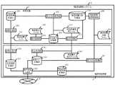
図1は、本実施形態に係る電話通信システム1のハードウェア構成を示すブロック図である。電話通信システム1は、発信先の電話5との電話通信の管理を行うシステムであり、制御装置2と、制御装置2と接続する複数の電話発信装置3と、を備える。本実施形態の電話通信システム1は、N台(Nは2以上の整数)の電話発信装置3(電話発信装置3−1〜電話発信装置3−N)を備えるとする。 FIG. 1 is a block diagram showing a hardware configuration of the
制御装置2は、接続される複数の電話発信装置3へ発信要求を振り分ける。また、制御装置2は、電話発信装置3の状態監視を行う。 The
電話発信装置3は、制御装置2によって制御され、制御装置2から発信要求に基づいて、ネットワーク4を介して発信先電話5へ電話の発信を行う。また、電話発信装置3は、発信先電話5からの応答を受け付ける。すなわち、電話発信装置3は発信先電話5との通信を行う装置である。 The
ネットワーク4は、例えば、電話回線やインターネット回線である。本実施形態ではネットワーク4は複数の電話回線で構成される。 The
制御装置2および電話発信装置3は、例えばPCサーバなどのサーバ機能を備えるコンピュータ装置によって実現する。なお、図1に示していないが、制御装置2および電話発信装置3は、HDD(ハードディスクドライブ)などの記憶装置を備える。なお、記憶装置は、装置ごとに備えてもよいし、複数の装置が1つの記憶装置を共有してもよい。 The
図2は、電話通信システム1の機能構成の一例を示すブロック図である。なお、電話発信システム1は、電話発信装置3をN台備えるが、ここでは代表の1台のみブロック図に示す。 FIG. 2 is a block diagram illustrating an example of a functional configuration of the
図2に示すように、制御装置2は、要求登録部201と、発信要求記憶部202と、振分処理部203と、発信装置状態記憶部204と、結果受信部205と、発信結果記憶部206と、第1の状態取得部207と、発信装置状態登録部208とを備える。発信要求記憶部202と、発信装置状態記憶部204と、発信結果記憶部217とは、1つの記憶装置によって実現してもよいし、複数の記憶装置によって実現してもよい。このような構成により、制御装置2は発信要求を電話発信装置3に振り分ける。 As shown in FIG. 2, the
要求登録部201は、発信要求を発信要求記憶部202に記憶する。発信要求は、例えば発信要求ファイル209として制御装置2に入力される。要求登録部201は、発信要求ファイル209が入力されると、発信要求テーブル22を作成し、作成した発信要求テーブル22を発信要求記憶部202に記憶する。 The
図3は、発信要求テーブル22の一例を示す図である。図3に示すように、発信要求テーブル22は、発信要求ごとに、識別子である発信要求No221と、発信を行う日時である発信要求日時222と、発信先電話5の電話番号223と、発信要求が振分先の電話発信装置3に送信済みであるかを示す要求送信済フラグ224(未送信:0、送信済:1とする)と、発信要求の振分先の電話発信装置3の識別子である要求送信先装置ID225と、を格納する。 FIG. 3 is a diagram illustrating an example of the transmission request table 22. As shown in FIG. 3, the transmission request table 22 includes, for each transmission request, a
制御装置2は、発信要求日時222に発信要求記憶部202に格納される日時を登録する。 The
振分処理部203は、発信要求と、電話発信装置3毎の状態情報(以下、発信装置状態情報という)とに基づいて振分数の算出を行う。振分数は、各電話発信装置3に振り分ける発信要求の件数である。 The
振分処理部203は電話発信装置3毎の振分数に応じて、発信要求テーブル22の要求送信済フラグ224が未送信の発信要求先装置ID225に振分先の電話発信装置のIDを登録する。The
発信装置状態情報は、発信装置状態記憶部204に記憶されている。発信装置状態情報は、各電話発信装置3における状態取得処理において取得され、制御装置2に送信される。状態取得処理については後述する。 The transmission device state information is stored in the transmission device
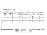
図4に発信装置状態記憶部204に記憶された発信装置状態テーブル24の一例を示す。 FIG. 4 shows an example of the transmission device state table 24 stored in the transmission device
電話発信装置状態テーブル24は、発信要求先の電話発信装置3の識別子である装置ID241と、電話発信装置3が異常かどうかを示す装置状態フラグ242と、装置ごとの全回線数243と、空き回線数244と、未発信の発信要求の件数を示す待ち件数245と、発信先電話5からの応答がない発信要求の件数を示すリトライ待ち件数246と、を格納する。 The telephone transmission device state table 24 includes a
すなわち、振分処理部203は、発信装置状態情報テーブル24に格納された発信装置状態情報に基づいて、各電話発信装置3に振分数分の発信要求(以下、発信要求振分情報という)を発信要求記憶部202から抽出し、振分先の電話発信装置3に送信する。装置状態フラグ242に「1」が格納されている異常状態の電話発信装置3は振分処理の対象とはならず、振分数は算出されない。図4に示すように、本実施形態の発信装置状態テーブル24では、装置ID241に格納されたIDが「3〜(N−1)」の電話発信装置3−3〜電話発信装置3−(N−1)は、装置状態フラグ242に「1」が格納されており、振分数は算出されない。 That is, the
発信結果受信部205は、電話発信装置3の電話発信に対する応答結果が格納された発信結果を受信する。結果受信部205は受信した発信結果を発信結果記憶部206に記憶する。 The outgoing call
発信結果記憶部206は、電話発信装置3による発信結果が格納された発信結果テーブル26を記憶する。図5に示すように、発信結果テーブル26は、発信要求ごとに、識別子である発信要求No261と、電話発信日時262と、電話の音声を記憶する音声ファイルの識別子である音声ファイルID263と、電話発信の回数を示すリトライ回数264と、応答がある場合に格納される応答日時265と、切断日時266、を格納する。 The transmission
第1の状態取得部207は、電話発信装置3の発信結果および状態情報に基づいて、発信要求を更新する。すなわち、第1の状態取得部207は、発信結果テーブル26および発信装置状態テーブル24に基づいて、発信要求テーブル22を更新する。 The first
具体的には、第1の状態取得部207は、発信装置状態テーブル24に格納された発信装置状態に基づいて、異常が発生している電話発信装置3がないかを確認する。異常が発生している電話発信装置3があれば、第1の状態取得部207は、発信装置異常ファイル210に当該電話発信装置のIDを記憶する。 Specifically, the first
第1の状態取得部207は、異常が発生している電話発信装置3がある場合、異常発生中の電話発信装置3に振り分けられた発信要求のうち、未応答の発信要求に対して、再度の振分処理が行われるように、発信要求の更新処理を行う。すなわち、異常発生中の電話発信装置3のIDが要求送信先装置ID225に格納された発信要求の発信要求のうち、発信結果テーブル26の応答日時265が格納されていない未応答の発信要求について、要求送信済みフラグ224を未送信の状態に戻す。これにより、異常発生中の電話発信装置3に振り分けられた発信要求のうち未応答の発信要求について、振分処理部203により再度の振分処理が行われる。 If there is a
発信装置状態登録部208は、電話発信装置3から送信された発信装置状態情報を発信装置状態記憶部204に記憶する。 The transmission device
具体的には、発信装置状態登録部208は、電話発信装置3から受信した発信装置状態ファイル212よりデータを取得し、発信装置状態テーブル24に格納する。 Specifically, the transmission device
電話発信装置3は、取込処理部301と、発信キュー記憶部302と、音声発信応答部303と、応答結果記憶部304と、結果送信部305と、回線状態記憶部306と、第2の状態取得部307とを備える。 The
取込処理部301は、制御装置2から受信した発信要求振分ファイル308に基づいて、発信キューを作成し発信キュー記憶部302に記憶する。発信要求振分ファイル308は、振分処理部203により振り分けられた発信要求が格納されたファイルである。 The
音声発信応答部303は、発信キュー記憶部302に記憶された発信キューに基づいて、ネットワーク4を介して自動音声による電話を発信する。すなわち、音声発信応答部303は、制御装置2から振り分けられた発信要求に基づいて発信先電話5に電話発信を行い、自動音声による案内を行う。自動音声電話発信時に相手先が話中である場合は、発信キューの該当する発信要求データを、リトライ待ち状態として更新する。 The voice
音声発信応答部303は、発信先電話3からの応答結果を応答結果記憶部304に記憶する。応答結果は、結果送信部305によって、制御装置2に送信される。 The voice
また、音声発信応答部303は、電話発信の際に、ネットワーク4における各回線の状態を取得し、回線状態記憶部306に記憶する。回線状態は、例えば、使用中、未使用、および回線異常の3種類であり、各回線の識別子と対応付けられ、回線状態記憶部306に記憶される。
第2の状態取得部307は、電話発信装置3の状態情報を取得し、制御装置2に送信する。例えば、第2の状態取得部307は、電話発信装置3が異常かどうかを確認する。また第2の状態取得部307は、発信キュー記憶部302から残っている発信要求の件数である発信待ち件数と、発信したが応答がなかった発信要求の件数である発信リトライ件数とを取得する。また、第2の状態取得部307は、回線状態記憶部306から、未使用の電話回線数(空き回線数)を取得する。第2の状態取得部307は取得した発信待ち件数、発信リトライ件数、および空き回線数を格納した発信装置状態ファイル212を作成し、制御装置2に送信する。In addition, the voice
The second
図6乃至図10を参照して、本実施形態の電話通信システム1における動作の一例について説明する。本実施形態の電話通信システム1は電話発信処理および状態監視処理を行う。 An example of the operation in the
図6は、電話通信システム1における電話発信処理の一例を示すフローチャートである。 FIG. 6 is a flowchart showing an example of a telephone call process in the
制御装置2に発信要求として発信要求ファイル209が入力されると、要求登録部201は、発信要求ファイル209を発信要求記憶部202に登録する発信要求登録処理を行う(ステップS1)。 When the
振分処理部203は、発信要求記憶部202に記憶された各発信要求を各電話発信装置3に振り分ける発信要求振分処理を行う(ステップS2)。なお、この振分処理は、ステップS1の発信要求登録処理後に順次実行されてもよいし、あらかじめ設定された所定の時間が経過すると実行されてもよい。もしくはあらかじめ設定された件数の発信要求が登録された場合に実行されるようにすることも可能である。 The
ここで、図7を参照して、本実施形態の発信要求振分処理の一例について説明する。図7は、電話通信システム1の振分処理部203による振分処理の一例を示すフローチャートである。 Here, with reference to FIG. 7, an example of the transmission request distribution process of this embodiment is demonstrated. FIG. 7 is a flowchart showing an example of distribution processing by the
振分処理部203は、発信装置状態テーブル24に格納された各電話発信装置3の状態を取得する(ステップS21)。続いて、振分処理部203は、異常が発生している電話発信装置3を確認する(ステップS22)。具体的には、振分処理部203は、第1の状態取得部207によって検出された異常状態の電話発信装置3の識別子が記載された発信装置異常ファイル210を取得する。もしくは、振分処理部203は、発信装置状態テーブル24の装置状態フラグ242に「1」が格納された電話発信装置3の装置ID241を抽出してもよい。 The
振分処理部203は、全ての電話発信装置3に異常が発生している場合(ステップS23がYes)、発信要求振分処理を終了する。 The
全ての電話発信装置3が異常状態でない場合(ステップS23がNo)、振分処理部203は、発信装置状態テーブル24にから、異常状態ではない電話発信装置3の装置ID241を取得する(ステップS24)。すなわち、N台の電話発信装置3のうち、識別子が発信装置異常ファイル210に記載されていない電話発信装置3を電話発信状態情報テーブル24から取得する。本実施形態では、発信装置状態テーブル24における装置ID241が「1」〜「N−1」である電話発信装置3−3〜電話発信装置3−(N−1)は、状態フラグ262に「1」が格納されており、電話発信装置3−3〜電話発信装置3−(N−1)の装置ID261は発信装置異常ファイル210に格納されているとする。 When all the
振分処理部203は、振分先の電話発信装置3に送信済みではない発信要求を取得する(ステップS25)。すなわち、振分処理部203は、発信要求記憶部202の発信要求テーブル22の要求送信済フラグが「0」である発信要求を取得する。 The
振分処理部203は、後述する振分数算出アルゴリズムに従い、ステップS25で取得した発信要求について、各電話発信装置3に対する振分数を算出する(ステップS26)。 The
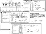
以下、本実施形態の振分数算出アルゴリズムの一例について説明する。振分数算出アルゴリズムの一例として、以下の式(1)に記載した振分率算出式に基づいて、各電話発信装置3の振分率を算出する方法を説明する。振分率は、各電話発信装置3の負荷度合に応じた割合である。算出された振分率を発信要求の合計値にかけた数値が振分数である。 Hereinafter, an example of the distribution number calculation algorithm of the present embodiment will be described. As an example of the distribution number calculation algorithm, a method of calculating the distribution rate of each
なお、振分数算出に用いる値は発信装置状態記憶部204の発信装置状態テーブル24から取得される。なお、以下の全電話発信装置3とは、ステップS24において振分対象として取得されたすべての電話発信装置3であり、ここでは、電話発信装置3−1、3−2、3−Nの3台である。 The value used for the distribution number calculation is acquired from the transmission device state table 24 of the transmission device
電話発信装置3の振分率D
=電話発信装置3の余裕率の重みA×(電話発信装置3の余裕率a÷全電話発信装置3の余裕率a合計)+電話発信装置3の空き回線率の重みB×(電話発信装置3の空き回線率b÷全電話発信装置3の空き回線率b合計)…式(1)
電話発信装置3の余裕率aとは、電話発信装置3における発信待ちの発信要求の少なさである。Distribution ratio D of the
= Weight of margin ratio A of
The margin rate “a” of the
余裕率aを算出する式の一例を以下の式(2)に示す。 An example of an equation for calculating the margin rate a is shown in the following equation (2).
電話発信装置3の余裕率a
=1−(電話発信装置3の待ち件数245+電話発信装置3のリトライ待ち件数246)÷(全電話発信装置3の待ち件数245の合計+全電話発信装置3のリトライ待ち件数246の合計)…式(2)
本実施形態では、全電話発信装置3の待ち件数245の合計は10であり、全電話発信装置3のリトライ待ち件数246の合計は7である。Margin rate a of the
= 1− (Number of waiting calls 245 of the
In the present embodiment, the total number of waiting
電話発信装置3の空き回線率bは、電話発信装置3に接続するネットワーク4の全回線に対する空き回線の割合である。空き回線率bを算出する式の一例を以下の式(3)に示す。 The free line rate b of the
電話発信装置3の空き回線率b=電話発信装置3の空き回線数244÷全電話発信装置3の全回線数243の合計…式(3)
本実施形態では、全発信装置3の全回線数の合計は、「63」である。Free line rate b of the
In the present embodiment, the total number of all lines of all transmitting
余裕率の重みAと、空き回線率の重みBとは、振分率の合計値を100%にするための係数である。余裕率の重みAを算出する式の一例を以下の式(4)に示す。 The margin ratio weight A and the idle line ratio weight B are coefficients for setting the total value of the distribution ratio to 100%. An example of an equation for calculating the margin ratio weight A is shown in the following equation (4).
余裕率の重みA=
(全電話発信装置3の待ち件数245の合計+全電話発信装置3リトライ待ち件数246の合計)÷(全電話発信装置3の待ち件数245の合計+全電話発信装置3リトライ待ち件数246の合計+全電話発信装置3の空き回線数244の合計)…式(4)
本実施形態では、全電話発信装置3の空き回線数244の合計は19である。Margin ratio weight A =
(Total of waiting
In the present embodiment, the total number of
空き回線率の重みBを算出する式の一例を以下の式(5)に示す。なお、
空き回線率の重みB=
(全電話発信装置3の空き回線数244の合計)÷(全電話発信装置3の待ち件数245の合計+全電話発信装置3リトライ待ち件数246の合計+全電話発信装置3の空き回線264数の合計)…式(5)
図8を参照して、本実施形態の振分数算出処理における余裕率について説明する。An example of an equation for calculating the weight B of the idle line rate is shown in the following equation (5). In addition,
Free line rate weight B =
(Total of the number of
With reference to FIG. 8, the margin rate in the distribution number calculation process of the present embodiment will be described.
電話発信装置3−1の余裕率a1は、以下の式(6)で算出される。The margin rate a1 of the telephone transmission device 3-1 is calculated by the following equation (6).
電話発信装置3−1の余裕率a1=1−(電話発信装置3−1の待ち件数245+電話発信装置3−1のリトライ待ち件数246)÷(全電話発信装置3の待ち件数の合計265+全電話発信装置3のリトライ待ち件数246の合計)…式(6)
電話発信装置3−2の余裕率a2は、以下の式(7)で算出される。Margin ratio a1 = 1 of telephone call device 3-1 (number of waiting calls 245 of
Margina 2 telephone transmitter 3-2 is calculated by the following equation (7).
電話発信装置3−2の余裕率a2=1−(電話発信装置3−2の待ち件数245+電話発信装置3−2のリトライ待ち件数246)÷(全電話発信装置3の待ち件数の合計265+全電話発信装置3のリトライ待ち件数246の合計)…式(7)
電話発信装置3−Nの余裕率aNは、以下の式(8)で算出される。Margin rate a2 of the telephone transmission device 3-2 = 1− (the number of waiting for the telephone transmission device 3-2 245 + the number of waiting for the retry of the telephone transmission device 3-2 246) ÷ (the total number of waiting for all the
The margin rate aN of the telephone transmission device 3-N is calculated by the following equation (8).
電話発信装置3−Nの余裕率aN=1−(電話発信装置3−Nの待ち件数245+電話発信装置3−Nのリトライ待ち件数246)÷(全電話発信装置3の待ち件数の合計265+全電話発信装置3のリトライ待ち件数246の合計)…式(8)
図9を参照して、本実施形態の振分数算出処理における空き回線率について説明する。Margin ratio aN = 1− (the number of waiting calls 245 of the telephone calling device + the number of waiting calls 246 of the telephone calling device 3-N) ÷ (the total number of waiting calls of all the
With reference to FIG. 9, the idle line rate in the distribution number calculation process of the present embodiment will be described.
電話発信装置3−1の空き回線率b1は、以下の式(9)で算出される。The free line rate b1 of the telephone transmission device 3-1 is calculated by the following equation (9).
電話発信装置3−1の空き回線率b1=電話発信装置3−1の空き回線数244÷全電話発信装置3の全回線数243の合計…式(9)
電話発信装置3−2の余裕率b2は、以下の式(10)で算出される。Free line rate b1 of telephone transmission device 3-1 = total number of
Marginb 2 of the telephone transmitter 3-2 is calculated by the following equation (10).
電話発信装置3−2の空き回線率b2=電話発信装置3−2の空き回線数244÷全電話発信装置3の全回線数243の合計…式(10)
電話発信装置3−Nの空き回線率bNは、以下の式(11)で算出される。
Free line rate b2 of telephone transmission device 3-2 = total number of
Free line rateb N of the telephone transmitter 3-N is calculated by the following equation (11).
電話発信装置3−Nの空き回線率bN=電話発信装置3−Nの空き回線数244÷全電話発信装置3の全回線数243の合計…式(11)
電話発信装置3−1の振分率D1を算出する式を以下の式(12)に示す。Free line rate bN of telephone transmission device 3-N = total number of
Shown in Equation (12) follows an equation for calculating the split ratioD 1 of the telephone transmitter 3-1.
電話発信装置3−1の振分率D1
=余裕率の重みA1×{余裕率a1÷(余裕率a1+余裕率a2+余裕率aN)}+空き回線率の重みB×{空き回線率b1÷(空き回線率b1+空き回線率b2+空き回線率bN)}=0.32…式(12)
電話発信装置3−2の振分率D2を算出する式を以下の式(13)に示す。Distribution ratio D1 of the telephone transmitter 3-1
= Weight of margin ratio A1 * {margin ratio a1 ÷ (margin ratio a1 + margin ratio a2 + margin ratio aN )} + weight of free line ratio B × {free line ratio b1 ÷ (free line ratio b1 + free line rate b2 + free line rate bN )} = 0.32 Equation (12)
It is shown in equation (13) below formula for calculating the distribution ratioD 2 of the telephone transmitter 3-2.
電話発信装置3−2の振分率D2
=余裕率の重みA2×{余裕率a2÷(余裕率a1+余裕率a2+余裕率aN)}+空き回線率の重みB×{空き回線率b2÷(空き回線率b1+空き回線率b2+空き回線率bN)}=0.486…式(13)
電話発信装置3−Nの振分率DNを算出する式を以下の式(14)に示す。Distribution ratio D2 of the telephone transmitter 3-2
= Weight of margin ratio A2 × {margin ratio a2 ÷ (margin ratio a1 + margin ratio a2 + margin ratio aN )} + weight of free line ratio B × {free line ratio b2 ÷ (free line ratio b1 + free line rate b2 + free line rate bN )} = 0.486 Equation (13)
It is shown in equation (14) below formula for calculating the distribution ratio DN of the telephone transmitter 3-N.
電話発信装置3−Nの振分率DN
=余裕率の重みAN×{余裕率aN÷(余裕率a1+余裕率a2+余裕率aN)}+空き回線率の重みB×{空き回線率bN÷(空き回線率b1+空き回線率b2+空き回線率bN)}=0.194…式(14)
各電話発信装置3の振分率Dを発信要求数にかけた数が、各電話発信装置3への振分数である。Distribution ratio DN of telephone transmitter 3-N
= Weight rate weight AN × {Margin rate aN ÷ (Margin rate a1 + Margin rate a2 + Margin rate aN )} + Free line rate weight B × {Free line rate bN ÷ (Free line rate b1 + free line rate b2 + free line rate bN )} = 0.194 (14)
The number obtained by multiplying the distribution rate D of each
以上の算出結果から、例えば、未発信の発信要求が発信要求データテーブル26に200件存在した場合、電話発信装置3−1には64件、電話発信装置3−2には97件、電話発信装置3−Nには39件の発信要求が振り分けられ、各電話発信装置3の負荷状況に見合った要求件数が送信されることになる。 From the above calculation results, for example, when there are 200 unsent call requests in the call request data table 26, 64 calls are sent to the phone call device 3-1, 97 calls are sent to the phone call device 3-2, and phone calls are sent. 39 transmission requests are distributed to the device 3-N, and the number of requests corresponding to the load status of each
図7の説明に戻る。振分処理部203は、ステップS26において、電話発信装置3ごとの振分数を算出すると、算出した電話発信装置3ごとの振分数に基づいて、発信要求テーブル22に格納された発信要求を抽出し、要求送信先装置ID225に振り分け先の電話発信装置3の識別子を格納する(ステップS27)。 Returning to the description of FIG. In step S26, the
振分処理部203は、要求送信先装置ID225に基づいて、電話発信装置3ごとに発信要求日時22の古い順から発信要求ファイル(以下、発信要求振分ファイル308という)を作成する。この時、発信要求テーブル22の要求送信済フラグ224を「1:送信済」に更新する。作成された発信要求振分ファイル308は、振分処理部203により、振分先の電話発信装置3に送信される。これにより、図6のステップS2における発信要求振分処理は終了する。 Based on the request transmission
図6の説明に戻る。ステップS2において、振分処理部203に作成された発信要求振分ファイル308は振分先の電話発信装置3に送信される。電話発信装置3の取り込み処理部306は、受信した発信要求振分ファイル308を取り込み、発信キューを作成して発信キュー記憶部302に記憶する(ステップS3)。 Returning to the description of FIG. In step S <b> 2, the call
音声発信応答部303は、発信キュー記憶部302に記憶された発信キューに基づいて、ネットワーク4の回線を通して自動音声電話を発信し、発信先からの応答結果を応答結果記憶部304に記憶する(ステップS4)。 The voice
結果送信部305は、応答結果記憶部304に記憶された応答結果を制御装置2に送信する(ステップS5)。ステップS5の応答結果送信は、応答結果記憶部304が更新されたタイミングで行ってもよいし、あらかじめ設定した周期で行うようにしてもよい。 The
制御装置2の結果受信部205は、電話発信装置3から応答結果が格納された発信結果ファイル211を受信すると、発信結果記憶部203に記憶する(ステップS6)。すなわち、結果受信部205は電話発信装置3から受信した応答結果に基づいて、発信結果テーブル26を更新する。具体的には、発信要求No261毎に、電話発信日時262、応答日時265、切断日時266を記憶する。発信先電話5から応答があった場合は、音声が記憶されたファ2イルのID263が記憶される。また、同一の発信要求No261が応答結果に含まれていた場合は、リトライ回数264を1増やす。 When receiving the
発信結果テーブル26が更新されると、第1の状態取得部207は、発信装置状態テーブル24を確認する(ステップS7)。なお、ステップS7の処理は、発信結果テーブルが更新されるたびに行うのではなく、あらかじめ設定したタイミングで行うようにしてもよい。 When the transmission result table 26 is updated, the first
発信装置状態テーブル24の装置状態フラグ262が「1(異常)」の電話発信装置3がある場合(ステップS8がYes)、第1の状態取得部207は、発信要求テーブル22を確認し、異常状態の電話発信装置3のIDが要求送信先装置ID225に格納されており、かつ、要求送信済みフラグ224が「1:送信済み」の発信要求を抽出する(ステップS9)。 When there is a
第1の状態取得部207は、抽出した発信要求の発信要求No221を用いて発信結果記憶部206の発信結果テーブル26を検索する。検索の結果、発信結果テーブル26の発信要求No261に、発信要求No221と一致するものがない場合に、抽出した発信要求No221に対応付けられた要求送信済みフラグ224を「0:未送信」にする(ステップS10)。これにより、電話通信システム1における電話発信処理は終了する。 The first
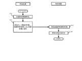
続いて、図10を参照して電話通信システム1における状態監視処理の一例について説明する。 Next, an example of state monitoring processing in the
音声発信応答部303は、ネットワーク4の回線状態情報を取得し回線状態記憶部306に保存する(ステップS31)。回線状態情報とは、例えば、回線状態の正常もしくは異常、全回線数、空回線数、使用中回線数、などである。ステップS31は、例えば、あらかじめ設定した周期が到来すると開始する。もしくは音声発信応答部303による電話発信が行われるたびに開始されてもよい。 The voice
第2の状態取得部307は、発信キュー記憶部302から未発信の待ち件数、リトライ件数を含む発信キュー状態情報を取得し、回線状態記憶部306に記憶された回線状態情報とともに、制御装置2に送信する(ステップS32)
発信装置状態登録部208は、受信した発信キュー状態情報と回線状態情報が記載された発信装置状態ファイル212に基づいて、発信装置状態テーブル24を更新する(ステップS33)。The second
The transmission device
第1の状態取得部207は、更新された発信装置状態テーブル24から装置状態フラグ242が「1:異常」の電話発信装置3のID241を抽出し、発信装置異常ファイル210に記憶する(ステップS34)。 The first
電話通信システム1における電話発信処理と状態監視処理は同時並行で行われてもよい。 The telephone call process and the state monitoring process in the
上述のように、本実施形態の電話通信システム1によると、各電話発信装置3の負荷状況に見合った件数の発信要求が振分られ、送信されるため、効率のよい電話発信処理を行うことが可能となる。 As described above, according to the
すなわち、本実施形態の電話通信システム1は、複数回線を制御する自動音声応答部を備える電話発信装置3を複数備える構成において、各電話発信装置3の回線数、空回線数、待ち件数、リトライ件数に基づいて、発信待ちの発信要求を最適に振り分けることにより、電話発信業務を効率化することができる。 That is, the
また、本実施形態で電話通信システム1によると、回線障害などで発信できない状態になった電話発信装置3が確認されると、この電話発信装置3に振り分けられた未応答の発信要求を正常な電話発信装置3に再度振り分けることが可能である。すなわち、本実施形態の電話発信システム1によると、発信要求を電話発信装置3の負荷状態に合わせて分散させ、かつ発信に失敗もしくは応答がないなどにより、待ち状態となっている発信要求の再振分処理が可能となる。これにより、電話発信の効率化を可能とする電話通信システム1を実現できる。 Further, according to the
以上、本実施形態に係る電話通信システム1について説明したが、この実施形態は、例として提示したものであり、発明の範囲を限定することは意図していない。この新規な実施の形態は、その他の様々な形態で実施されることが可能であり、発明の要旨を逸脱しない範囲で、種々の省略、置き換え、変更を行うことができる。この実施の形態やその変形は、発明の範囲や要旨に含まれるとともに、特許請求の範囲に記載された発明とその均等の範囲に含まれる。 The
例えば、電話発信装置3の空き回線率bは、振分率算出対象の電話発信装置3の全回線数243に対する電空き回線数244の割合としてもよい。 For example, the free line rate b of the
また、振分率の算出式は以下の式(15)としてもよい。 Also, the calculation formula for the distribution ratio may be the following formula (15).
電話発信装置3の振分率D
=電話発信装置3の余裕率の重みA×(電話発信装置3の余裕率a÷全電話発信装置3の余裕率a合計)+電話発信装置3の空き回線率の重みB×(電話発信装置3の空き回線数c÷全電話発信装置3の空き回線数cの合計)…式(15)
また、電話発信処理のステップS7〜S10の処理は、ステップS6に続いて行うのでなく、所定のタイミングで行うようにしてもよい。Distribution ratio D of the
= Weight of margin ratio A of
Moreover, you may make it perform the process of step S7-S10 of a telephone call process at a predetermined timing instead of performing it following step S6.
1…電話通信システム、2…制御装置、3…電話発信装置、4…ネットワーク、5…発信先電話、201…要求登録部、202…発信要求記憶部、203…振分処理部、204…発信装置状態記憶部、205…結果受信部、206…発信結果記憶部、207…第1の状態取得部、208…発信装置状態登録部、209…発信要求ファイル、210…発信装置異常ファイル、211…発信結果ファイル、212…発信装置状態ファイル、301…取込処理部、302…発信キュー記憶部、303…音声発信応答部、304…応答結果記憶部、305…結果送信部、306…回線状態記憶部、307…第2の第2の状態取得部307…発信要求振分ファイル DESCRIPTION OF
Claims (5)
Translated fromJapanese前記制御装置は、
前記発信要求の識別子と、発信先電話の電話番号と、前記電話発信装置に送信済みであるかどうかを示す送信済みフラグとを対応づけた発信要求を記憶する発信要求記憶部と、
前記電話発信装置の識別子、状態フラグ、全回線数、空き回線数、未発信数、および未応答数を含む前記電話発信装置の状態情報を記憶する状態情報記憶部と、
前記状態情報記憶部に前記電話発信装置の状態情報を登録する登録部と、
前記状態情報記憶部に記憶された状態情報のうち、前記状態フラグが正常である電話発信装置の状態情報を取得し、前記状態情報に含まれる前記回線数、前記空き回線数、前記未発信数、および前記未応答数に基づいて、電話発信装置ごとに前記発信要求を振り分けた振分発信要求を作成する振分部と、
前記電話発信装置による発信が行われた前記発信要求の識別子と応答結果とが対応付けられた発信結果を受信する受信部と、
前記発信結果と前記状態情報に基づいて、状態が異常である電話発信装置に送信された前記発信要求のうち、未応答の発信要求の前記送信済みフラグを未送信の状態に更新する第1の状態取得部と、を備える、
電話通信システム。A telephone communication system comprising: a plurality of telephone transmission devices that make a call based on a plurality of transmission requests via a network composed of a plurality of lines; and a control device that distributes the plurality of transmission requests to the plurality of telephone transmission devices. There,
The control device includes:
A call request storage unit that stores a call request that associates an identifier of the call request, a telephone number of a call destination telephone, and a transmitted flag that indicates whether the call has already been transmitted to the telephone call device;
A status information storage unit for storing status information of the telephone call device including an identifier of the call transmission device, a status flag, the total number of lines, the number of empty lines, the number of untransmitted calls, and the number of unanswered calls;
A registration unit for registering the state information of the telephone transmission device in the state information storage unit;
Among the state information stored in the state information storage unit, the state information of thetelephone transmission device whose state flag is normal is acquired, and the number of lines, the number of free lines, the number of untransmitted calls included in the state information And a distribution unit that creates a distribution transmission request that distributesthe transmission request for each telephone transmission device based on the number of unanswered calls;
A receiving unit that receives a transmission result in which an identifier and a response result of the transmission request that has been transmitted by the telephone transmission device are associated;
Based on the transmission result and the state information, a first flag for updating the transmitted flag of an unanswered transmission request to an untransmitted state among the transmission requests transmitted to the telephone transmission device having an abnormal state. A state acquisition unit,
Telephone communication system.
前記電話番号に基づいて、前記複数の回線を介して自動音声による電話発信を行う音声発信応答部と、 Based on the telephone number, a voice call response unit for making a call by automatic voice through the plurality of lines;
発信済みの前記振分発信要求と、当該振分発信要求に対する応答結果とを含む発信結果を制御装置に送信する送信部と、 A transmission unit that transmits a transmission result including the distribution transmission request that has already been transmitted and a response result to the distribution transmission request to the control device;
前記ネットワークの空き回線数と、未発信および未応答の前記振分発信要求の件数と、前記電話発信装置の状態を取得し、取得したデータを前記制御装置に送信する第2の状態取得部と、を更に備える、 A second state acquisition unit that acquires the number of free lines in the network, the number of unallocated and unanswered distribution call requests, the state of the telephone transmission device, and transmits the acquired data to the control device; , Further comprising
請求項1に記載の電話通信システム。 The telephone communication system according to claim 1.
請求項2に記載の電話通信システム。 The telephone communication system according to claim 2.
前記発信要求の識別子と、発信先電話の電話番号と、前記電話発信装置に送信済みであるかどうかを示す送信済みフラグとを対応づけて記憶する過程と、
前記電話発信装置の識別子、状態フラグ、全回線数、空き回線数、未発信数、および未応答数を含む前記電話発信装置の状態情報に基づいて、前記電話発信装置ごとに発信要求を振り分けた振分発信要求を作成する過程と、
前記電話発信装置による発信が行われた前記発信要求の識別子と応答結果とが対応付けられた発信結果を受信する過程と、
前記発信結果と前記状態情報とに基づいて、状態が異常である電話発信装置に送信された前記発信要求のうち、未応答の発信要求の前記送信済みフラグを未送信の状態に更新する過程と、
前記電話番号に基づいて、前記複数の回線を介して自動音声による電話発信を行う過程と、
発信済みの前記振分発信要求と当該振分発信要求に対する応答結果とを含む発信結果を前記制御装置に送信する過程と、
前記ネットワークの空き回線数と、未発信および未応答の前記振分発信要求の件数と、前記電話発信装置の状態を取得し、取得したデータを前記制御装置に送信する過程と、
前記データに基づいて、前記状態フラグ、前記空き回線数、前記未発信数、および前記未応答数を更新する過程と、を備える電話通信方法。A telephone communication method for a telephone communication system, comprising: a plurality of telephone transmission devices that make a call to a plurality of telephones via a network composed of a plurality of lines; and a control device that distributes a call request to the plurality of telephone transmission devices. There,
Storing the identifier of the call request, the telephone number of the call destination telephone, and a transmitted flag indicating whether or not the call has been transmitted to the telephone call device;
Based on the state information of the telephone transmission device including the identifier of the telephone transmission device, the status flag, the total number of lines, the number of free lines, the number of untransmitted calls, and the number of unanswered calls, the call request is distributed for each telephone transmission device. The process of creating a dispatch request,
Receiving a call result in which an identifier and a response result of the call request sent by the telephone call device are associated; and
Updating the transmitted flag of an unanswered call request to an untransmitted state among the call requests transmitted to the telephone call device whose state is abnormal based on the call result and the state information; ,
Based on the telephone number, a process of making an automatic voice call through the plurality of lines,
A process of transmitting a transmission result including the distribution transmission request that has already been transmitted and a response result to the distribution transmission request to the control device;
Obtaining the number of free lines in the network, the number of unallocated and unanswered distribution call requests, the status of the telephone call device, and transmitting the acquired data to the control device;
A telephone communication method comprising: updating the status flag, the number of idle lines, the number of untransmitted calls, and the number of unanswered calls based on the data.
前記発信要求の識別子と、発信先電話の電話番号と、前記電話発信装置に送信済みであるかどうかを示す送信済みフラグとを対応づけて記憶する機能と、
前記電話発信装置の識別子、状態フラグ、全回線数、空き回線数、未発信数、および未応答数を含む前記電話発信装置の状態情報を記憶する機能と、
前記電話発信装置の状態情報を登録する機能と、
前記発信要求を、前記状態情報に基づいて前記電話発信装置ごとに振り分けた振分発信要求を作成する機能と、
前記電話発信装置による発信が行われた前記発信要求の識別子と応答結果とが対応付けられた発信結果を受信する機能と、
前記発信結果と前記状態情報に基づいて、状態が異常である電話発信装置に送信された前記発信要求のうち、未応答の発信要求の前記送信済みフラグを未送信の状態に更新する機能と、を実現させる電話通信プログラム。A computer having a plurality of telephone call devices for making a call based on a plurality of call requests via a network composed of a plurality of lines,
A function for storing an identifier of the call request, a telephone number of a call destination telephone, and a transmitted flag indicating whether or not the call has been transmitted to the telephone call device;
A function for storing the status information of the telephone call device including the identifier of the telephone call device, a status flag, the total number of lines, the number of free lines, the number of unsent calls, and the number of unanswered
A function of registering status information of the telephone call device;
A function for creating a distribution call request that distributes the call request for each of the telephone transmission devices based on the status information;
A function of receiving a transmission result in which an identifier and a response result of the transmission request transmitted by the telephone transmission device are associated;
Based on the transmission result and the state information, a function of updating the transmitted flag of an unanswered transmission request to an untransmitted state among the transmission requests transmitted to the telephone transmission device having an abnormal state; A telephone communication program that realizes
Priority Applications (1)
| Application Number | Priority Date | Filing Date | Title |
|---|---|---|---|
| JP2016090446AJP6471117B2 (en) | 2016-04-28 | 2016-04-28 | Telephone communication system, telephone communication method, telephone communication program |
Applications Claiming Priority (1)
| Application Number | Priority Date | Filing Date | Title |
|---|---|---|---|
| JP2016090446AJP6471117B2 (en) | 2016-04-28 | 2016-04-28 | Telephone communication system, telephone communication method, telephone communication program |
Publications (2)
| Publication Number | Publication Date |
|---|---|
| JP2017200092A JP2017200092A (en) | 2017-11-02 |
| JP6471117B2true JP6471117B2 (en) | 2019-02-13 |
Family
ID=60238290
Family Applications (1)
| Application Number | Title | Priority Date | Filing Date |
|---|---|---|---|
| JP2016090446AActiveJP6471117B2 (en) | 2016-04-28 | 2016-04-28 | Telephone communication system, telephone communication method, telephone communication program |
Country Status (1)
| Country | Link |
|---|---|
| JP (1) | JP6471117B2 (en) |
Families Citing this family (1)
| Publication number | Priority date | Publication date | Assignee | Title |
|---|---|---|---|---|
| CN113760445B (en)* | 2020-11-24 | 2024-11-19 | 北京沃东天骏信息技术有限公司 | A service switching method and device |
Family Cites Families (6)
| Publication number | Priority date | Publication date | Assignee | Title |
|---|---|---|---|---|
| JP4177835B2 (en)* | 1999-12-21 | 2008-11-05 | Jfeシステムズ株式会社 | Call center operation method and apparatus |
| JP4430791B2 (en)* | 2000-07-05 | 2010-03-10 | エヌ・ティ・ティ・コミュニケーションズ株式会社 | Outgoing communication proxy method |
| US7103173B2 (en)* | 2001-07-09 | 2006-09-05 | Austin Logistics Incorporated | System and method for preemptive goals based routing of contact records |
| JP4840101B2 (en)* | 2006-11-22 | 2011-12-21 | 沖電気工業株式会社 | IP call center system |
| JP2010050937A (en)* | 2008-08-25 | 2010-03-04 | Promise Co Ltd | Automatic call origination system |
| JP5331995B2 (en)* | 2010-04-13 | 2013-10-30 | 株式会社日立情報制御ソリューションズ | Call center system |
- 2016
- 2016-04-28JPJP2016090446Apatent/JP6471117B2/enactiveActive
Also Published As
| Publication number | Publication date |
|---|---|
| JP2017200092A (en) | 2017-11-02 |
Similar Documents
| Publication | Publication Date | Title |
|---|---|---|
| US10171661B2 (en) | System and method of distributed maintenance of contact center state | |
| CN103718578B (en) | Method and device for notification messages and providing notification messages | |
| JP2017091569A5 (en) | ||
| US9178988B2 (en) | Unified call logs | |
| CN104796561A (en) | Agent distribution method, CTI (Computer Telephony Integration) equipment, terminal and agent distribution system | |
| US8229096B1 (en) | Optimizing on-premise conferencing solutions | |
| JP6471117B2 (en) | Telephone communication system, telephone communication method, telephone communication program | |
| US11805201B2 (en) | Call processing apparatus, call processing method, call processing system and call processing program | |
| JP2011139401A (en) | Telephone processing system and telephone terminal | |
| JP4385229B2 (en) | Connection management server, call center reconnection management method, and call center reconnection management program | |
| JP5331995B2 (en) | Call center system | |
| JP6863177B2 (en) | Communication control device, communication control program, and communication control method | |
| JP5545887B2 (en) | Distributed recovery method and network system | |
| US12238247B2 (en) | System and method for reconnecting an inbound originated call | |
| EP2475157B1 (en) | Method and apparatus for managing telephone services of a user communication device when a server providing those telephone services is unavailable | |
| JP5654401B2 (en) | Incoming and outgoing call monitoring system for telephone system | |
| KR20120117153A (en) | Message service apparatus and system for providing number portability, and method thereof | |
| CN110324502B (en) | System and method for switching automatic call distribution unit | |
| US20150023152A1 (en) | Method for changing terminal accommodation destination, server apparatus and terminal apparatus | |
| JP5913398B2 (en) | Call relief method for PBX device, PBX device, and PBX control program | |
| JP6787176B2 (en) | Management communication device, management communication program, and management communication method | |
| JP5516273B2 (en) | SIP telephone system having group incoming call function | |
| CA2953849C (en) | System and method of contact identification dissemination | |
| JP2010239529A (en) | Load distribution system, and computer program | |
| JP6017077B1 (en) | Emergency call management device |
Legal Events
| Date | Code | Title | Description |
|---|---|---|---|
| A621 | Written request for application examination | Free format text:JAPANESE INTERMEDIATE CODE: A621 Effective date:20170925 | |
| RD02 | Notification of acceptance of power of attorney | Free format text:JAPANESE INTERMEDIATE CODE: A7422 Effective date:20170925 | |
| A977 | Report on retrieval | Free format text:JAPANESE INTERMEDIATE CODE: A971007 Effective date:20180914 | |
| A131 | Notification of reasons for refusal | Free format text:JAPANESE INTERMEDIATE CODE: A131 Effective date:20180925 | |
| A521 | Written amendment | Free format text:JAPANESE INTERMEDIATE CODE: A523 Effective date:20181122 | |
| TRDD | Decision of grant or rejection written | ||
| A01 | Written decision to grant a patent or to grant a registration (utility model) | Free format text:JAPANESE INTERMEDIATE CODE: A01 Effective date:20181221 | |
| A61 | First payment of annual fees (during grant procedure) | Free format text:JAPANESE INTERMEDIATE CODE: A61 Effective date:20190121 | |
| R150 | Certificate of patent or registration of utility model | Ref document number:6471117 Country of ref document:JP Free format text:JAPANESE INTERMEDIATE CODE: R150 |