JP6470763B2 - Production system - Google Patents
Production systemDownload PDFInfo
- Publication number
- JP6470763B2 JP6470763B2JP2016565604AJP2016565604AJP6470763B2JP 6470763 B2JP6470763 B2JP 6470763B2JP 2016565604 AJP2016565604 AJP 2016565604AJP 2016565604 AJP2016565604 AJP 2016565604AJP 6470763 B2JP6470763 B2JP 6470763B2
- Authority
- JP
- Japan
- Prior art keywords
- rail
- robot
- self
- carriage
- arm
- Prior art date
- Legal status (The legal status is an assumption and is not a legal conclusion. Google has not performed a legal analysis and makes no representation as to the accuracy of the status listed.)
- Active
Links
Images


Classifications
- B—PERFORMING OPERATIONS; TRANSPORTING
- B25—HAND TOOLS; PORTABLE POWER-DRIVEN TOOLS; MANIPULATORS
- B25J—MANIPULATORS; CHAMBERS PROVIDED WITH MANIPULATION DEVICES
- B25J5/00—Manipulators mounted on wheels or on carriages
- B25J5/02—Manipulators mounted on wheels or on carriages travelling along a guideway
- B—PERFORMING OPERATIONS; TRANSPORTING
- B25—HAND TOOLS; PORTABLE POWER-DRIVEN TOOLS; MANIPULATORS
- B25J—MANIPULATORS; CHAMBERS PROVIDED WITH MANIPULATION DEVICES
- B25J13/00—Controls for manipulators
- B—PERFORMING OPERATIONS; TRANSPORTING
- B25—HAND TOOLS; PORTABLE POWER-DRIVEN TOOLS; MANIPULATORS
- B25J—MANIPULATORS; CHAMBERS PROVIDED WITH MANIPULATION DEVICES
- B25J19/00—Accessories fitted to manipulators, e.g. for monitoring, for viewing; Safety devices combined with or specially adapted for use in connection with manipulators
- B25J19/0025—Means for supplying energy to the end effector
- B—PERFORMING OPERATIONS; TRANSPORTING
- B25—HAND TOOLS; PORTABLE POWER-DRIVEN TOOLS; MANIPULATORS
- B25J—MANIPULATORS; CHAMBERS PROVIDED WITH MANIPULATION DEVICES
- B25J5/00—Manipulators mounted on wheels or on carriages
- B—PERFORMING OPERATIONS; TRANSPORTING
- B25—HAND TOOLS; PORTABLE POWER-DRIVEN TOOLS; MANIPULATORS
- B25J—MANIPULATORS; CHAMBERS PROVIDED WITH MANIPULATION DEVICES
- B25J9/00—Programme-controlled manipulators
- B25J9/0009—Constructional details, e.g. manipulator supports, bases
- B25J9/0027—Means for extending the operation range
- B—PERFORMING OPERATIONS; TRANSPORTING
- B25—HAND TOOLS; PORTABLE POWER-DRIVEN TOOLS; MANIPULATORS
- B25J—MANIPULATORS; CHAMBERS PROVIDED WITH MANIPULATION DEVICES
- B25J9/00—Programme-controlled manipulators
- B25J9/0093—Programme-controlled manipulators co-operating with conveyor means
- B—PERFORMING OPERATIONS; TRANSPORTING
- B25—HAND TOOLS; PORTABLE POWER-DRIVEN TOOLS; MANIPULATORS
- B25J—MANIPULATORS; CHAMBERS PROVIDED WITH MANIPULATION DEVICES
- B25J9/00—Programme-controlled manipulators
- B25J9/0096—Programme-controlled manipulators co-operating with a working support, e.g. work-table
- B—PERFORMING OPERATIONS; TRANSPORTING
- B25—HAND TOOLS; PORTABLE POWER-DRIVEN TOOLS; MANIPULATORS
- B25J—MANIPULATORS; CHAMBERS PROVIDED WITH MANIPULATION DEVICES
- B25J9/00—Programme-controlled manipulators
- B25J9/02—Programme-controlled manipulators characterised by movement of the arms, e.g. cartesian coordinate type
- B25J9/04—Programme-controlled manipulators characterised by movement of the arms, e.g. cartesian coordinate type by rotating at least one arm, excluding the head movement itself, e.g. cylindrical coordinate type or polar coordinate type
- B25J9/041—Cylindrical coordinate type
- B25J9/042—Cylindrical coordinate type comprising an articulated arm
- B—PERFORMING OPERATIONS; TRANSPORTING
- B25—HAND TOOLS; PORTABLE POWER-DRIVEN TOOLS; MANIPULATORS
- B25J—MANIPULATORS; CHAMBERS PROVIDED WITH MANIPULATION DEVICES
- B25J9/00—Programme-controlled manipulators
- B25J9/06—Programme-controlled manipulators characterised by multi-articulated arms
- B—PERFORMING OPERATIONS; TRANSPORTING
- B25—HAND TOOLS; PORTABLE POWER-DRIVEN TOOLS; MANIPULATORS
- B25J—MANIPULATORS; CHAMBERS PROVIDED WITH MANIPULATION DEVICES
- B25J9/00—Programme-controlled manipulators
- B25J9/10—Programme-controlled manipulators characterised by positioning means for manipulator elements
- B25J9/102—Gears specially adapted therefor, e.g. reduction gears
- B—PERFORMING OPERATIONS; TRANSPORTING
- B25—HAND TOOLS; PORTABLE POWER-DRIVEN TOOLS; MANIPULATORS
- B25J—MANIPULATORS; CHAMBERS PROVIDED WITH MANIPULATION DEVICES
- B25J9/00—Programme-controlled manipulators
- B25J9/10—Programme-controlled manipulators characterised by positioning means for manipulator elements
- B25J9/106—Programme-controlled manipulators characterised by positioning means for manipulator elements with articulated links
- B—PERFORMING OPERATIONS; TRANSPORTING
- B25—HAND TOOLS; PORTABLE POWER-DRIVEN TOOLS; MANIPULATORS
- B25J—MANIPULATORS; CHAMBERS PROVIDED WITH MANIPULATION DEVICES
- B25J9/00—Programme-controlled manipulators
- B25J9/16—Programme controls
- B25J9/1615—Programme controls characterised by special kind of manipulator, e.g. planar, scara, gantry, cantilever, space, closed chain, passive/active joints and tendon driven manipulators
- B25J9/162—Mobile manipulator, movable base with manipulator arm mounted on it
- B—PERFORMING OPERATIONS; TRANSPORTING
- B25—HAND TOOLS; PORTABLE POWER-DRIVEN TOOLS; MANIPULATORS
- B25J—MANIPULATORS; CHAMBERS PROVIDED WITH MANIPULATION DEVICES
- B25J9/00—Programme-controlled manipulators
- B25J9/16—Programme controls
- B25J9/1679—Programme controls characterised by the tasks executed
- B25J9/1687—Assembly, peg and hole, palletising, straight line, weaving pattern movement
- B—PERFORMING OPERATIONS; TRANSPORTING
- B25—HAND TOOLS; PORTABLE POWER-DRIVEN TOOLS; MANIPULATORS
- B25J—MANIPULATORS; CHAMBERS PROVIDED WITH MANIPULATION DEVICES
- B25J5/00—Manipulators mounted on wheels or on carriages
- B25J5/007—Manipulators mounted on wheels or on carriages mounted on wheels
- B—PERFORMING OPERATIONS; TRANSPORTING
- B25—HAND TOOLS; PORTABLE POWER-DRIVEN TOOLS; MANIPULATORS
- B25J—MANIPULATORS; CHAMBERS PROVIDED WITH MANIPULATION DEVICES
- B25J9/00—Programme-controlled manipulators
- B25J9/02—Programme-controlled manipulators characterised by movement of the arms, e.g. cartesian coordinate type
- B25J9/04—Programme-controlled manipulators characterised by movement of the arms, e.g. cartesian coordinate type by rotating at least one arm, excluding the head movement itself, e.g. cylindrical coordinate type or polar coordinate type
- B25J9/041—Cylindrical coordinate type
- B25J9/042—Cylindrical coordinate type comprising an articulated arm
- B25J9/043—Cylindrical coordinate type comprising an articulated arm double selective compliance articulated robot arms [SCARA]
- Y—GENERAL TAGGING OF NEW TECHNOLOGICAL DEVELOPMENTS; GENERAL TAGGING OF CROSS-SECTIONAL TECHNOLOGIES SPANNING OVER SEVERAL SECTIONS OF THE IPC; TECHNICAL SUBJECTS COVERED BY FORMER USPC CROSS-REFERENCE ART COLLECTIONS [XRACs] AND DIGESTS
- Y02—TECHNOLOGIES OR APPLICATIONS FOR MITIGATION OR ADAPTATION AGAINST CLIMATE CHANGE
- Y02T—CLIMATE CHANGE MITIGATION TECHNOLOGIES RELATED TO TRANSPORTATION
- Y02T10/00—Road transport of goods or passengers
- Y02T10/60—Other road transportation technologies with climate change mitigation effect
- Y02T10/70—Energy storage systems for electromobility, e.g. batteries
- Y—GENERAL TAGGING OF NEW TECHNOLOGICAL DEVELOPMENTS; GENERAL TAGGING OF CROSS-SECTIONAL TECHNOLOGIES SPANNING OVER SEVERAL SECTIONS OF THE IPC; TECHNICAL SUBJECTS COVERED BY FORMER USPC CROSS-REFERENCE ART COLLECTIONS [XRACs] AND DIGESTS
- Y02—TECHNOLOGIES OR APPLICATIONS FOR MITIGATION OR ADAPTATION AGAINST CLIMATE CHANGE
- Y02T—CLIMATE CHANGE MITIGATION TECHNOLOGIES RELATED TO TRANSPORTATION
- Y02T10/00—Road transport of goods or passengers
- Y02T10/60—Other road transportation technologies with climate change mitigation effect
- Y02T10/7072—Electromobility specific charging systems or methods for batteries, ultracapacitors, supercapacitors or double-layer capacitors
- Y—GENERAL TAGGING OF NEW TECHNOLOGICAL DEVELOPMENTS; GENERAL TAGGING OF CROSS-SECTIONAL TECHNOLOGIES SPANNING OVER SEVERAL SECTIONS OF THE IPC; TECHNICAL SUBJECTS COVERED BY FORMER USPC CROSS-REFERENCE ART COLLECTIONS [XRACs] AND DIGESTS
- Y02—TECHNOLOGIES OR APPLICATIONS FOR MITIGATION OR ADAPTATION AGAINST CLIMATE CHANGE
- Y02T—CLIMATE CHANGE MITIGATION TECHNOLOGIES RELATED TO TRANSPORTATION
- Y02T90/00—Enabling technologies or technologies with a potential or indirect contribution to GHG emissions mitigation
- Y02T90/10—Technologies relating to charging of electric vehicles
- Y02T90/14—Plug-in electric vehicles
Landscapes
- Engineering & Computer Science (AREA)
- Robotics (AREA)
- Mechanical Engineering (AREA)
- Health & Medical Sciences (AREA)
- General Health & Medical Sciences (AREA)
- Orthopedic Medicine & Surgery (AREA)
- Manipulator (AREA)
- Charge And Discharge Circuits For Batteries Or The Like (AREA)
- Current-Collector Devices For Electrically Propelled Vehicles (AREA)
- Electric Propulsion And Braking For Vehicles (AREA)
Description
Translated fromJapanese本発明は、台車とこれに支持されたロボットアームとを備える自走式関節ロボットを用いた生産システムに関する。 The present invention relates to a production system using a self-propelled joint robot including a carriage and a robot arm supported by the carriage.
従来、電気・電子部品などの組み立て工程において、ワークの搬送ラインに沿って一連に配置された作業者と作業用ロボットが協働して作業を行う、人間・ロボット協働型のライン生産方式が提案されている。例えば、特許文献1には、人間・ロボット協働型のライン生産方式に利用される作業用双腕ロボットが開示されている。 Previously, a human / robot collaborative line production system was proposed, in which workers and work robots arranged in series along the workpiece transfer line work together in the assembly process of electrical and electronic parts. Has been. For example,
この特許文献1の作業用双腕ロボットは、胴体と、頭と、2本の腕と、各腕の先端に設けられた手と、胴体の下部を支持する台車とを備えている。この作業用双腕ロボットを作業台に設置するときは、操縦者が、自由回転可能な駆動輪で支持された台車を作業台まで手押しで移動させてから、台車を位置固定させる。そして、ロボットが作業中に移動して作業位置の修正が必要になったときには、制御装置が、腕を伸ばして腕の先端に設けられたアンカピンを作業台に設けられたアンカポイントに係合させ、台車を自由回転可能な駆動輪で支持された状態へ切り替えて、伸ばした腕を引き寄せることによって、台車を望ましい作業位置へ移動させる。 The working double-arm robot of
また、特許文献2では、ロボットを利用したセル生産方式のロボットシステムが示されている。このロボットシステムでは、作業者に代わってロボットが部品の取り付けから組み立て、加工、検査などを行う。この特許文献2のロボットシステムは、ロボットと作業台とを備えている。作業台には、作業台側固定部材が設けられている。また、ロボットは、ロボットアームを有する本体部と、本体部が固定された台座部と、台座部を移動させる操舵駆動輪とを備え、作業台側固定部材と結合されるロボット側固定部材が台座部に設けられている。そして、作業台側固定部材とロボット側固定部材が結合されることによって、ロボットが作業台に固定されるとともに、作業台からロボットへ電力が供給される。 In Patent Document 2, a cell production type robot system using a robot is shown. In this robot system, a robot performs assembly, processing, inspection, and the like on behalf of an operator from mounting of parts. The robot system of Patent Document 2 includes a robot and a work table. A work table side fixing member is provided on the work table. The robot includes a main body having a robot arm, a pedestal to which the main body is fixed, and a steering drive wheel that moves the pedestal, and the robot-side fixing member coupled to the worktable-side fixing member is a pedestal. Provided in the department. Then, by combining the work table side fixing member and the robot side fixing member, the robot is fixed to the work table and power is supplied from the work table to the robot.
上記特許文献1の作業用双腕ロボットでは、ロボットの作業位置の修正に腕を利用するため、ロボットの作業中に作業位置を修正することができない。また、上記特許文献1の作業用双腕ロボットでは、ロボットの作業位置を固定することを目的としてロボットの位置の修正を行っているため、ロボットが作業位置から移動しながら作業を行うことは想定されていない。 In the working double-arm robot described in
また、上記特許文献2のロボットは、作業台側固定部材とロボット側固定部材が結合されることによって、ロボットが作業台に固定されるため、ロボットが作業台に対して移動しながら作業を行うことはできない。 Moreover, since the robot of the above-mentioned patent document 2 is fixed to the work table by combining the work table side fixing member and the robot side fixing member, the robot moves while moving relative to the work table. It is not possible.
本発明は以上の事情に鑑みてされたものであり、その目的は、自走可能な関節ロボットを利用した生産システムであって、関節ロボットが移動しながら作業を行うことが可能なものを提案することにある。 The present invention has been made in view of the above circumstances, and an object thereof is to propose a production system using a self-propelled joint robot that can perform work while the joint robot moves. There is to do.
本発明の一態様に係る生産システムは、水平に延びるレールと、前記レールの延伸方向と平行に当該レールに沿って自走可能な自走式関節ロボットと、前記レールに沿って設けられた複数の処理装置又は前記レールに沿って延びるベルトコンベヤを含むライン搬送装置と、前記レールに沿って且つ前記処理装置又は前記ライン搬送装置と前記レールを介して反対側に配置された複数の補助作業台とを備えている。前記処理装置又は前記ライン搬送装置は、その側部から突出するブラケットを介して前記レールを支持する。そして、前記ロボットが、サーボモータによって駆動される前記レールに沿って自走するための少なくとも1つの動作軸を有する台車と、前記台車から前記レールへ向けて突設され、前記レールに対し係脱可能に係合するスライダと、前記台車に支持され、サーボモータにより駆動され且つ関節を構成する少なくとも1つの動作軸を有するロボットアームと、前記ロボットアームの先端に設けられたエンドエフェクタと、前記台車内に設けられた制御ユニットとを有する。隣接する前記補助作業台の間に前記自走式関節ロボットの作業エリアが形成され、前記作業エリア内に作業基準位置が規定され、当該作業エリアを形成する前記補助作業台が前記作業基準位置にある前記自走式関節ロボットの前記ロボットアームの可動範囲の内側に位置する部分と外側に位置する部分とを有する。そして、前記制御ユニットが、前記自走式関節ロボットが作業を開始する前に、前記自走式関節ロボットが前記作業基準位置へ移動するように、前記台車の動作軸を動作させ、前記自走式関節ロボットが作業をしている間に、前記ロボットアームの動作軸と前記台車の動作軸とが協働することによって前記ロボットアーム又は前記エンドエフェクタに規定された制御点が目標位置へ到達するように、前記ロボットアームの動作軸及び前記台車の動作軸を動作させ、前記目標位置が前記作業基準位置にある前記自走式関節ロボットの前記ロボットアームの可動範囲外にある目標位置を含むことを特徴としている。A production system according to an aspect of the present invention includes a horizontally extending rail, a self-propelled joint robot capable of self-propelling along the rail in parallel with the extending direction of the rail, anda plurality of the robotsprovided along the rail. A processing apparatus or a line conveying device including a belt conveyor extending along the rail, and a plurality of auxiliary worktables disposed along the rail and on the opposite side of the processing apparatus or the line conveying device via the rail And .The said processing apparatus or the said line conveying apparatus supports the said rail via the bracket which protrudes from the side part. The robot has a carriage having at least one operation axis for self-propelling along the rail driven by a servo motor, and projects from the carriage toward the rail, and is engaged with and disengaged from the rail. A slider that can be engaged, a robot arm that is supported by the carriage, is driven by a servo motor, and has at least one operation axis that forms a joint; an end effector provided at a tip of the robot arm; and the carriage And a control unit provided in the vehicle.A work area of the self-propelled joint robot is formed between the adjacent auxiliary worktables, a work reference position is defined in the work area, and the auxiliary worktable forming the work area is at the work reference position. The self-propelled joint robot has a portion located inside a movable range of the robot arm and a portion located outside. Then, the control unit, before saidself-propelled articulated robot to begin, the soself-propelled articulated robot is moved tothe working reference position, by operating the operation shaft of the bogie, theself While the articulated robot is working, the operation axis of the robot arm and the operation axis of the carriage cooperate to reach a control point defined by the robot arm or the end effector. As described above, the movement axis of the robot arm and the movement axis of the carriageare moved, and the target position is included in a target position outside the movable range of the robot arm of the self-propelled joint robot at the work reference position. It is characterized by.
上記生産システムでは、ロボットアームの基台となる台車をレールに沿って移動させながら、ロボットアームに作業を行わせることができる。 In the production system described above, the robot arm can be operated while moving a carriage that is a base of the robot arm along the rail.
本発明によれば、自走可能な関節ロボットを利用した生産システムであって、関節ロボットが移動しながら作業を行うことが可能なものを実現することができる。 According to the present invention, it is possible to realize a production system using a self-propelled joint robot that can perform work while the joint robot moves.
次に、図面を参照して本発明の実施の形態を説明する。本発明に係る生産システムは、例えば、ライン生産方式又はセル生産方式で製品又は部品を生産するためのシステムであって、レールと、レールに沿って自走可能な少なくとも1つ以上の自走式関節ロボットとを備えている。この自走式関節ロボットでは、従来作業員によって行われていたワークに対する、移送、パーツの組み付けや配置換え、姿勢変換などの作業のうち少なくとも1つが行われる。以下では、本発明に係る生産システムの第1実施形態及び第2実施形態についてそれぞれ説明する。 Next, embodiments of the present invention will be described with reference to the drawings. The production system according to the present invention is, for example, a system for producing a product or a part by a line production method or a cell production method, and at least one self-propelled type capable of self-propelled along the rail. It has a joint robot. In this self-propelled articulated robot, at least one of operations such as transfer, parts assembly and rearrangement, and posture conversion performed on a workpiece that has been conventionally performed by a worker is performed. Below, 1st Embodiment and 2nd Embodiment of the production system which concern on this invention are each demonstrated.
〔第1実施形態〕
先ず、本発明の第1実施形態に係る生産システム100について説明する。図1は本発明の第1実施形態に係る生産システム100の平面図、図2は図1に示す生産システム100のレール55と自走式関節ロボット1の概略構成を示す側面図、図3は図1に示す生産システム100のレール55と当該レール55に係合された自走式関節ロボット1の概略構成を示す側面図である。図1〜3に示すように、本実施形態に係る生産システム100は、レール55と、レール55に沿って自走可能な少なくとも1つ以上の自走式関節ロボット(以下、単に「ロボット1」ということがある)とを備えている。[First Embodiment]
First, the
本実施形態に係る生産システム100は、レール55に沿って配置された複数の処理装置51と、レール55に沿って且つレール55を介して複数の処理装置51と反対側に配置された複数の補助作業台52とを更に備えている。複数の処理装置51の各々にはレール55へ向けて突出するブラケット56が設けられており、このブラケット56によってレール55がほぼ水平に延伸するように支持されている。以下では、レール55の延伸方向を便宜的にX方向といい、このX方向と直交する水平方向をY方向といい、上下方向をZ方向ということとする。 The
複数の補助作業台52はX方向に並べられており、X方向に隣り合う補助作業台52の間がロボット1の作業エリアWAとなっている。 The plurality of auxiliary work tables 52 are arranged in the X direction, and the work area WA of the
レール55の上部には、レール55の延伸方向であるX方向と平行に当該レール55に沿って延びるラック57が設けられている。本実施形態に係るラック57は、レール55の全長に亘って設けられている。但し、ラック57はレール55のうち作業エリアWA及びその周囲にのみ部分的に設けられていてもよい。また、本実施形態に係るラック57はレール55に一体的に形成されている。但し、ラック57が形成されたラック部材がレール55と結合されることによって、レール55にラック57が設けられてもよい。 A
また、レール55には、レール55の延伸方向であるX方向と平行に当該レール55に沿って延びる送電部材44が設けられている。本実施形態に係る送電部材44は、レール55の全長に亘って設けられている。但し、送電部材44はレール55のうち作業エリアWA及びその周囲にのみ部分的に設けられていてもよい。送電部材44内には図示されない送電コイルが設けられている。この送電コイルは、当該送電コイルへ電流を供給する送電側コントローラ43などとともに、非接触式の電力電送システム40の送電側(一次側)モジュール40a構成している。送電側コントローラ43はACアダプタを介して商用電源と接続されている。 Further, the
ここで、ロボット1の構成について説明する。図4は自走式関節ロボット1の概略構成を示す正面図、図5は自走式関節ロボット1の概略構成を示す平面図である。図2〜5に示すように、ロボット1は、レール55に沿って自走可能な台車7と、レール55に対し係脱可能に係合するスライダ90と、台車7に支持された少なくとも1本のロボットアーム2A,2Bと、各ロボットアーム2A,2Bの先端に着脱可能に取り付けられエンドエフェクタ5と、画像処理装置64と、ロボットアーム2A,2B及び台車7の動作を制御する制御ユニット6とを備えている。エンドエフェクタ5の動作も制御ユニット6によって制御されてもよい。Here, the configuration of the
本実施形態に係るロボット1は、左右のロボットアーム2A,2Bを備えた双腕ロボットである。左右のロボットアーム2A,2Bは、独立して動作したり、互いに関連し合って動作したりすることが可能である。これにより、左右のロボットアーム2A,2Bで、各々別の作業を行ったり、協動して一つの作業を行ったりすることができる。但し、本発明に係るロボット1は、双腕ロボットに限定されず、少なくとも1本のロボットアームを備えていればよい。The
一方のロボットアーム2Aは、第1軸線L1まわりに回動する第1リンク21Aと、第1リンク21Aに当該第1リンク21Aの先端に規定された第2軸線L2Aまわりに回動可能に結合された第2リンク22Aとを備えている。同様に、他方のロボットアーム2Bは、第1軸線L1まわりに回動する第1リンク21Bと、第1リンク21Bに当該第1リンク21Bの先端に規定された第2軸線L2Bまわりに回動可能に結合された第2リンク22Bとを備えている。第1軸線L1と第2軸線L2A,L2Bは平行であり、本実施形態に係る第1軸線L1と第2軸線L2A,L2Bは垂直に延在している。One of the robot arm2 A includes a first link 21A which rotates about the first axis L1, the second axis L2A around the times specified in the tip of the the first link 21A first link 21A and a second link 22a which is rotatably coupled. Similarly, the other robot arm2 B, first link 21B is rotated about the first axis L1, the second axis defined on the first link 21B to the distal end of the first link 21B L2B and a second link 22B that is pivotally coupled around. The first axis L1 and the second axisL2 A, L2B are parallel, the first axis L1 of the present embodiment the second axisL2 A, L2B extends vertically.
2本のロボットアーム2A,2Bの第1リンク21A,21Bの第1軸線L1どうしは一致しており、一方のロボットアーム2Aの第1リンク21Aと他方のロボットアーム2Bの第1リンク21Bは上下に高低差を設けて配置されている。以下では、2本のロボットアーム2A,2Bのうち、第1リンク21Aが下方に位置する一方を第1アーム2Aとし、他方を第2アーム2Bとする。Two robot arms2 A,2 first link21 Aand B, 21 first and if the axis L1 ofB are consistent, the first link 21A and the other robot arm2 B of one of the robot arm2 A the first link 21B of which is disposed with a height difference in the vertical. Hereinafter, one of the two robot arms 2A and 2B where the first link 21A is positioned below is referred to as a first arm 2A , and the other is referred to as a second arm 2B.
ここで、第1アーム2Aの構造について詳細に説明する。第1アーム2Aの第1リンク21Aは、台車7の上面に固定された基軸20Aに、図示されない軸受を介して回動可能に支持されている。また、第1アーム2Aの第2リンク22Aは、第1リンク21Aの先端に図示されない軸受けを介して回動可能に支持されている。It will now be described in detail the structure of the first arm 2A. The first link 21A of the first arm 2A is the base shaft 20A fixed to the upper surface of the
第1リンク21Aの外形は、中空のリンク部材30Aにより形成されている。リンク部材30Aの内部には、第1リンク21Aを第1軸線L1まわりに回動駆動するための、サーボモータ91Aと動力伝達装置92Aが設けられている。動力伝達装置92Aは、回転トルクを調整するための減速機としての機能を併せ備えている。このように、第1アーム2Aは、サーボモータ91Aによって駆動され、基軸20Aと第1リンク21Aを結合する関節を構成する動作軸(第1軸A1A)を有している。The outer shape of the first link 21A is formed by a hollow link members 30A. Inside of the link member 30A, for rotatably driving the first link 21A to about the first axis L1, a servo motor 91A and the power transmission device 92A is provided. Power transmission device 92A has combined the functions of a reduction gear for adjusting the rotational torque. Thus, the first arm2 A is driven by a servo motor 91A, and has the operation shaft which constitutes a joint for coupling the base shaft 20A and the first link 21A (the first axis A1A).
また、リンク部材30Aの内部には、第2リンク22Aを第2軸線L2Aまわりに回動駆動するための、サーボモータ93Aと動力伝達装置94Aが設けられている。動力伝達装置94Aは、回転トルクを調整するための減速機としての機能を併せ備えている。このように、第1アーム2Aは、サーボモータ93Aによって駆動され、第1リンク21Aと第2リンク22Aを結合する関節を構成する動作軸(第2軸A2A)を有している。In the interior of the link member 30A, for rotatably driving the second link 22A in L2A about the second axis, the servo motor 93A and the power transmission device 94A is provided. Power transmission device 94A has combined the functions of a reduction gear for adjusting the rotational torque. Thus, the first arm2 A is driven by a servo motor 93A, has an operating shaft which constitutes a joint for coupling the first link 21A and the second link 22A (second axis A2A) Yes.
続いて、第2アーム2Bについて詳細に説明する。第2アーム2Bの基軸20Bは、第1アーム2Aの第1リンク21A上に固定されている。第2アーム2Bは、前述の第1アーム2Aと類似する構成を有している。そこで、各図面においては、第1アーム2Aの各構成要素には数字にアルファベットのAを添えた参照符号が付され、第2アーム2Bの各構成要素には数字にアルファベットのBを添えた参照符号が付されている。参照符号のうち数字部分の共通する構成要素は、第1アーム2Aと第2アーム2Bで共通する要素であって、機能及び形状が同一又は類似する。そして、第2アーム2Bの構造についての詳細な説明を、前述の第1アーム2Aの説明において参照符号に添えたアルファベットのAをアルファベットのBに読み替えることによって省略する。Next, the second arm2B will be described in detail. Cornerstone 20B of the second arm2 B is fixed to the first link on 21A of the first arm2 A. The second arm 2B has a configuration similar to the first arm 2A above. Therefore, in the drawings, the respective components of the first arm 2A numerical reference numerals accompanied by letters A is attached to, served with alphabet B in numbers to the components of the second arm 2B Reference numerals are assigned. Common components of numerical portion of the reference numerals, a component common to the first arm 2A and the second arm 2B, function and shape are the same or similar. Then, it omitted by replaced a detailed description of the structure of the second arm 2B, the A alphabet accompanied by a reference number in the description of the first arm 2A of aforementioned alphabet B.
次に、台車7について説明する。台車7は、直方体形状の筐体71と、筐体71の下部に設けられた複数のフリーキャスタ72と、筐体71の背面に設けられたハンドル73と、走行駆動装置80及び受電部材45とを備えている。本実施形態に係るロボット1では、スライダ90は台車7に設けられている。台車7の筐体71は中空状であって、筐体71の内部に制御ユニット6、制御ユニット6へ電力を供給する二次電池88、受電側コントローラ46、画像処理装置64、図示されないエア圧供給装置などが配設されている。また、筐体71の上部にはマシンビジョンカメラなどの少なくとも1つのカメラ87が設けられている。 Next, the
走行駆動装置80は、レール55に設けられたラック57と噛合可能なピニオンギア81と、動力源であるサーボモータ82と、サーボモータ82からピニオンギア81への動力伝達経路上に設けられた減速機83とを備えている。この構成の走行駆動装置80では、サーボモータ82の出力が減速機83で調整されてからピニオンギア81へ伝達される。走行駆動装置80はロボットアーム2A,2Bの外部軸装置であって、制御ユニット6によってサーボモータ82が制御されている。このように、台車7は、サーボモータ82によって駆動される動作軸(走行軸TA)を有している。The
スライダ90は、筐体71に回動可能に支持されたローラ95と、筐体71にアーム97を介して回動可能に支持されたローラ96とを備えている。アーム97は、基端部分97aと先端部分97bとに分割されており、基端部分97aと先端部分97bとはヒンジ97cによって回動可能に結合されている。アーム97の基端部分97aは筐体71に固定されている。アーム97の先端部分97bは、ローラ96を回動可能に支持している。 The
本実施形態に係る台車7には上記構成のスライダ90が2つ設けられており、これらのスライダ90は筐体71の前面において走行駆動装置80の両側に配置されている。スライダ90は、台車7の筐体71の前面に突設されており、ロボット1が作業エリアWAで作業しているときに台車7からレール55へ向けて突出する。 The
受電部材45は、筐体71の前面においてレール55に設けられた送電部材44と対応する高さ位置に設けられている。受電部材45内には図示されない受電コイルが設けられている。この受電コイルは、当該受電コイルで発生した誘導電流が供給される受電側コントローラ46などとともに、非接触式電力電送システム40の受電側(二次側)モジュール40bを構成している。受電側コントローラ46は制御ICを介して二次電池88と接続されており、受電側コントローラ46から二次電池88へ電力が供給される。 The
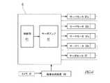
続いて、制御ユニット6について説明する。図6は自走式関節ロボット1の制御系統の概略構成を示すブロック図である。図6に示すように、制御ユニット6には、制御装置61と、サーボアンプ62とが設けられている。制御ユニット6には、画像処理装置64が接続されている。 Next, the
サーボアンプ62は、制御装置61から供給された制御信号(位置指令)に基づいて、第1アーム2Aの動作軸(即ち、第1軸A1Aと第2軸A2A)を動作させるサーボモータ91A,93A、第2アーム2Bの動作軸(即ち、第1軸A1Bと第2軸A2B)を動作させるサーボモータ91B,93B、及び、台車7の動作軸(即ち、走行軸TA)を動作させるサーボモータ82の各サーボモータへ駆動電流を供給するように構成されている。なお、サーボアンプ62は、各サーボモータ91A,93A,91B,93B,82に対応して設けられており、それらがまとめて図示されている。The
各サーボモータ91A,93A,91B,93B,82には、例えば、出力軸の回転量・回転角度・回転位置などを検出するロータリエンコーダなどの回転検出器が設けられており、この回転検出器で検出されたサーボモータの出力軸の少なくとも回転位置が制御装置61及びサーボアンプ62へ入力される。Each
制御装置61は、いわゆるコンピュータであって、CPU等の演算処理部と、ROM、RAM等の記憶部を有している(いずれも図示せず)。記憶部には、演算処理部が実行するプログラム、各種固定データ等が記憶されている。演算処理部は、外部装置とのデータ送受信を行う。また、演算処理部は、各種センサからの検出信号の入力や各制御対象への制御信号の出力を行う。制御装置61では、記憶装置に記憶されたプログラム等のソフトウェアを演算処理部が読み出して実行することにより、ロボット1の動作を制御するための処理が行われる。なお、制御装置61は単一のコンピュータによる集中制御により各処理を実行してもよいし、複数のコンピュータの協働による分散制御により各処理を実行してもよい。また、制御装置61は、マイクロコントローラ、プログラマブルロジックコントローラ(PLC)等から構成されていてもよい。 The
続いて、画像処理装置64について説明する。画像処理装置64は、カメラ87で撮像された画像又は映像を利用して、後述するマーカとロボット1(又は台車7)の相対的な位置関係を検出する手段である。画像処理装置64で検出されたマーカとロボット1の相対的な位置関係は制御ユニット6へ伝達される。画像処理装置64は、例えば、カメラ87から送られてきた映像信号を画像処理して、算出されたマーカの特徴量(面積、重心、長さ、位置など)に基づいてマーカとロボット1の相対的な位置関係を検出する演算処理装置などから構成されている。 Next, the
上記構成のロボット1では、制御ユニット6が、画像処理装置64、及び各サーボモータ91A,93A,91B,93B,82に設けられた回転検出器からの検出信号又は測定信号を取得し、各ロボットアーム2A,2Bの手先又はエンドエフェクタ5に規定された制御点の現在位置を演算する。そして、制御ユニット6は、制御点が所定のプログラムに則って所定の軌道に沿って目標位置へ移動するような、制御信号を生成する。この制御信号は、制御装置61からサーボアンプ62へ出力される。サーボアンプ62は、制御信号に応じた駆動電流をサーボモータ91A,93A,91B,93B,82へ供給する。このように、制御ユニット6は、ロボットアーム2A,2Bの動作軸と同様に台車7の動作軸に対しても、制御点の位置、方位、姿勢などを制御量として、その目標値に追従するような自動制御(即ち、サーボ制御)を行う。In the
続いて、エンドエフェクタ5について説明する。エンドエフェクタ5は、ロボット1が行う作業に応じて適切な構造のものが用いられる。そのため、ここでは、エンドエフェクタ5の一例について簡単に説明する。本実施形態に係るエンドエフェクタ5は、手首部5aと、手首部5aの先端に設けられたツール部5bとにより概ね構成されている。手首部5aは、ツール部5bを上下方向に移動させる昇降動作軸と、ツール部5bを垂直軸まわりに旋回させる旋回動作軸とを有している。手首部5aの昇降動作軸は、例えば、レールとスライダから成る直動機構とスライダを動作させるサーボモータによって実現される。また、手首部5a旋回動作軸は、例えば、出力軸がツール部5bと連結されたサーボモータによって実現される。 Next, the end effector 5 will be described. The end effector 5 has an appropriate structure according to the work performed by the
ここで、上記構成の生産システム100で行われる作業の一例を説明する。作業を開始するに前に、ロボット1は作業エリアWAで位置決めされる。 Here, an example of work performed in the
ロボット1は作業者によって作業エリアWAまで運ばれる。図1〜3に示すように、作業エリアWAへ運ばれたロボット1は、ローラ95がレール55の側面と当接し且つピニオンギア81がラック57と噛合するまでY方向へレール55に近づけられる。ここで、電力電送システム40の受電部材45は、送電部材44から電力を受電することができる程度に十分に近接している又は接触している。 The
上記のようにロボット1がレール55へ近づけられた状態で、スライダ90とレール55とが係合される。ここで、まず、アーム97の先端部分97bをヒンジ97cを回動中心として下方へ回動させることにより、ローラ96をレール55の側面と当接させる。次いで、図示されないロック機構でアーム97の先端部分97bの回動を規制する。このようにして、アーム97を台車7に対して下方へ回動させることによって、レール55がスライダ90の2つのローラ95,96の周面に挟み込まれて、スライダ90とレール55と係合した状態となる。なお、アーム97を台車7に対して上方へ回動させることによって、スライダ90とレール55の係合が解除された状態となる。このように、スライダ90はレール55に対し係脱可能であって、スライダ90がレール55と係合した状態と、これらの係合が解除された状態とを切り替えることができる。 The
上記のように、スライダ90がレール55に係合すると、ロボット1はレール55に対してY方向への移動が規制され、これにより、ロボット1がY方向に位置決めされる。次いで、ロボット1はX方向の位置決めと、Z方向の位置の較正とを行う。 As described above, when the
ロボット1のX方向の位置決めとZ方向の位置の較正のために、マーカと画像処理装置64が利用される。マーカは、作業エリアWAのレール55、処理装置51又はその周辺に設けられている。例えば、特定形状のマーカが処理装置51のロボット1との対峙面に設けられていたり、処理装置51のロボット1との対峙面の特定形状(例えば、ドアの外形など)がマーカとして利用されたり、或いは、レール55に特定形状のマーカが設けられていたりしてよい。そして、制御ユニット6は、画像処理装置64からマーカとロボット1の相対的な位置関係を取得し、これに基づいてロボット1の現在位置を得る。 A marker and an
制御ユニット6は、ロボット1のX方向の現在位置が目標位置である所定の作業基準位置へ到達するように、台車7の動作軸を制御する。制御ユニット6が台車7の動作軸を制御するにあたり、サーボモータ82が動作すると、ラック57と噛合しているピニオンギア81が回動し、その結果、ロボット1がレール55に沿ってX方向へ移動する。 The
また、制御ユニット6は、ロボット1のZ方向の現在位置と所定の作業基準位置のZ方向位置ズレ量を演算し、このZ方向位置ズレ量でロボット1の座標系又は目標位置を較正する。なお、ロボット1が昇降動作軸を備えている場合は、Z方向の位置を較正することに代えて、ロボット1のZ方向の現在位置が所定の作業基準位置へ到達するように昇降動作軸が制御されてもよい。 Further, the
上記のようにロボット1の作業エリアWAへの位置決めが行われたうえで、ロボット1は作業を開始する。本実施形態に係る生産システム100では、作業エリアWAに配置されたロボット1が、ワークWにパーツ59を組み付ける組付け作業と、パーツ59が組み付けられたワークWを処理装置51へ搬入する搬入作業と、処理装置51で処理された後のワークWを処理装置51から搬出する搬出作業を行う。 After the
上記の組付け作業では、ロボット1は、補助作業台52に載置されたワークWを作業台へ移動させ、補助作業台52に載置された部品棚から複数のパーツ59が収容された部品トレイを作業台へ移動させ、作業台上でワークWに複数のパーツ59を組み付ける。なお、ここでは作業台としてロボット1の台車7の除面が利用されている。 In the above assembling work, the
上記の搬入作業では、ロボット1は、作業台に置かれたワークWを保持し、処理装置51内の処理棚にワークWを載置する。上記の搬出作業では、ロボット1は、ワークWを処理装置51の処理棚から処理装置51の外へ搬出して補助作業台52へ載置する。処理装置51の開口部には図示されない自動ドアが設けられている。この自動ドアは、ロボット1がワークWを処理装置51へ搬入する際に開放される。なお、この自動ドアは、開口部の周囲に設けられた動体・静止体検知センサで物体(ロボットアームやワークなど)が検知されている間に開放される。また、この自動ドアは、ロボット1がタッチスイッチを操作することにより開閉されるものであってもよい。 In the above carry-in work, the
上記の作業の間、ロボット1の制御ユニット6は、ロボットアーム2A,2Bの動作軸と台車7の動作軸とが協働することによってロボットアーム2A,2B又はエンドエフェクタ5に規定された制御点が所定のプログラムに則って目標位置へ到達するように、ロボットアーム2A,2Bの動作軸及び台車7の動作軸を制御する。つまり、制御ユニット6では、ロボットアーム2A,2Bと台車7について、エンドエフェクタ5の先端位置などの特定の制御点の位置、方位、姿勢などを制御量として、その目標値に追従するようなサーボ制御が行われる。During the above operation, the
このように、ロボット1は、ロボットアーム2A,2Bの基台となる台車7を移動させながら、ロボットアーム2A,2Bで作業を行う。よって、ロボットアーム2A,2Bの可動範囲外にある目標位置へも、ロボット1の制御点を到達させることが可能となり、ロボット1の作業範囲が広がる。しかも、台車7の動作軸も制御ユニット6によってサーボ制御されるので、制御点を目標位置へ高い精度で移動させることができる。なお、ロボット1はX方向へ移動するが、送電部材44はX方向に延びる部材であるので、電力電送システム40によるロボット1への電力供給は継続される。Thus, the
以上に説明したように、本実施形態の生産システム100は、水平に延びるレール55と、レール55の延伸方向(X方向)と平行に当該レール55に沿って自走可能な自走式関節ロボット1とを備えている。本実施形態に係る生産システム100は、レール55に沿って配設された少なくとも1つのワークの処理装置51を備えており、ロボット1が行う作業には、処理装置51へワークを搬入したり、処理装置51からワークを搬出したりする作業が含まれている。 As described above, the
そして、本実施形態に係る生産システム100は、ロボット1が、レール55に沿って自走するための、サーボモータ82によって駆動される少なくとも1つの動作軸(走行軸TA)を有する台車7と、台車7からレール55へ向けて突設され、レール55に対し係脱可能に係合するスライダ90と、台車7に支持され、サーボモータ91A,93A,91B,93Bにより駆動され且つ関節を構成する少なくとも1つの動作軸(第1軸A1A,第2軸A2A,第1軸A1Bと第2軸A2B)を有するロボットアーム2A,2Bと、ロボットアーム2A,2Bの先端に設けられたエンドエフェクタ5と、台車7内に設けられ、ロボットアーム2A,2Bの動作軸と台車7の動作軸とが協働することによってロボットアーム2A,2B又はエンドエフェクタ5に規定された制御点が目標位置へ到達するように、ロボットアーム2A,2Bの動作軸及び台車7の動作軸を制御する制御ユニット6とを有することを特徴としている。The
このように、本実施形態に係るロボット1では、ロボット1の作業時に、ロボットアーム2A,2Bと台車7の協働により作業が行われる。つまり、ロボットアーム2A,2Bの基台となる台車7を移動させながら、ロボットアーム2A,2Bに作業を行わせることができる。よって、ロボットアーム2A,2Bの可動範囲外にある目標位置へも、ロボット1の制御点を到達させることが可能となり、ロボット1の作業範囲が広がる。しかも、台車7の動作軸も制御ユニット6によってサーボ制御されるので、制御点を目標位置へ高い精度で移動させることができる。As described above, in the
また、ロボット1のスライダ90がレール55を走行することによって、ロボット1がレール55に沿ってX方向へ移動する際に、レール55に対するロボット1のY方向の相対的位置は一定に保持される。また、ロボット1に振動や反力などが加わったときにも、レール55に対するロボット1のY方向の相対的位置は一定に保持される。よって、ロボット1の位置制御を単純化することができる。 Further, when the
更に、ロボット1のスライダ90はレール55から係脱可能であるので、スライダ90とレール55との係合を解除させると、ロボット1をレール55に対して自由に移動させることが可能となる。よって、ロボット1を作業エリアWAから外部へ移動させたり、ロボット1を他のロボット1と入れ替えたりすることが容易である。 Furthermore, since the
また、本実施形態では、ロボット1のスライダ90が、レール55の延伸方向(X方向)と直交する方向(Y方向)からレール55を挟み込む2つのローラ95,96と、台車7に回動可能に支持され2つのローラのうち一方(ローラ96)を保持するアーム97とを含んでいる。そして、ロボット1は、アーム97を台車7に対して回動させることによって、スライダ90が2つのローラ95,96の周面でレール55を挟み込むことによってレール55と係合した状態と、スライダ90とレール55の係合が解除された状態とを切り換え可能に構成されている。 Further, in this embodiment, the
このように、アーム97を回転させることにより、スライダ90とレール55との係合させたり、その係合を解除させたりすることができる。このように、レール55に対するスライダ90の係脱操作は簡易である。 Thus, by rotating the
また、上記実施形態に係る生産システム100は、電源に接続された送電側モジュール40aと、ロボット1に搭載され、送電側モジュール40aから電力を受電して当該ロボット1へ供給する受電側モジュール40bとを有する電力電送システム40を更に備えている。そして、送電側モジュール40aが、レール55の延伸方向と平行に当該レール55に沿って延びる送電部材44を含み、受電側モジュール40bが、スライダ90がレール55と係合しているときに送電部材44から電力を受電するように配設された受電部材45を含んでいる。 The
上記構成によれば、ロボット1のスライダ90がレール55と係合しているときに、送電側モジュール40aから受電側モジュール40bへ電力が電送され、受電側モジュール40bから電力がロボット1へ供給される。なお、本実施形態においては、受電側モジュール40bから二次電池88へ電力が供給され、二次電池88からロボット1の制御ユニット6へ電力が供給されるように構成されている。これにより、送電側モジュール40aから受電側モジュール40bへの電力供給が不安定となった場合でもロボット1へ安定して電力が供給される。 According to the above configuration, when the
なお、本実施形態では、送電部材44がレール55に付設されているが、送電部材44はこの態様に限定されない。例えば、送電部材44は、レール55から独立した部材として、ロボット1が走行する床面に設けられていてもよい。また、本実施形態では、非接触式の電力電送システム40を採用しているが、非接触式電力電送システム40は接触式であってもよい。接触式の電力電送システム40の場合は、例えば、送電部材44としてレール55に沿って延びる長尺な電極を用い、受電部材45として送電部材44の表面を滑動するローラ状又はスライダ状の電極を用いることができる。 In addition, in this embodiment, although the
また、本実施形態に係る生産システム100は、スライダ90がレール55と係合しているときにピニオンギア81と噛合するようにレール55の延伸方向と平行に当該レール55に沿って延びるラック57を備えている。そして、上記ピニオンギア81は、台車7の動作軸(走行軸TA)によって駆動される。 In addition, the
上記構成によれば、台車7の動作軸が動作することによって、ラック57と噛合しているピニオンギア81が回転し、その結果、台車7がX方向へ移動する。なお、本実施形態では、ラック57はレール55と一体的に設けられているが、ラック57はこの態様限定されない。例えば、ラック57は、レール55から独立した部材として、ロボット1が走行する床面に設けられていてもよい。 According to the above configuration, when the operation shaft of the
〔第2実施形態〕
次に、本発明の第2実施形態に係る生産システム100Bについて説明する。本実施形態に係る生産システム100Bはライン生産方式で製品又は部品を生産するためのシステムである。図7は本発明の第2実施形態に係る生産システム100Bの平面図であり、図8は図7に示す生産システム100Bのレール55と自走式関節ロボット1の概略構成を示す側面図である。なお、本実施形態の説明においては、前述の第1実施形態と同一又は類似の部材には図面に同一の符号を付し、説明を省略する場合がある。[Second Embodiment]
Next, a
図7及び図8に示す生産システム100Bは、レール55と、レール55に沿って自走可能な少なくとも1つ以上の自走式関節ロボット(以下、単に「ロボット1」ということがある)とを備えている。ロボット1は、上述の第1実施形態に係るロボット1と同様の構造及び機能を有するため、ロボット1についての詳細な説明は省略する。また、レール55も、上述の第1実施形態に係るレール55と同様の構造及び機能を有しており、X方向に延びるラック57と、X方向に延びる送電部材44が設けられている。 The
生産システム100Bは、レール55に沿ってワークWを搬送するライン搬送装置50を備えている。このライン搬送装置50は、例えば、ベルトコンベヤ501とその支持台502によって構成されている。ベルトコンベヤ501の上面は作業台として使用される。支持台502には、レール55へ向けて突出するブラケット56が設けられており、このブラケット56によってレール55がX方向へほぼ水平に延伸するように支持されている。 The
レール55に沿って、複数の補助作業台52が設けられている。複数の補助作業台52はX方向に並べられており、X方向に隣り合う補助作業台52の間がロボット1の作業エリアWAとなっている。補助作業台52には、ワークWに組み付けられる組付けパーツ53,54が載置されている。また、上記作業エリアWA又はその近傍に、マーカ86が設けられている。なお、マーカ86は、ロボット1が作業エリアWAに在るときにカメラ87で撮像できる位置に設けられている。 A plurality of auxiliary work tables 52 are provided along the
ここで、上記構成の生産システム100Bで行われる作業の一例を説明する。作業を開始するに前に、ロボット1は作業エリアWAで位置決めされる。 Here, an example of work performed in the
ロボット1は作業者によって作業エリアWAまで運ばれる。作業エリアWAへ運ばれたロボット1は、前述の第1実施形態と同様に、X方向及びY方向に位置決めされ、更に、Z方向に較正される。ロボット1はライン搬送装置50に固定されていないので、作業内容に応じてロボット1を入れ替えたり、ロボット1の数を増減したりすることができる。また、ライン搬送装置50に沿って配置されている複数のロボット1のうち一つが故障したときには、故障した一つのロボット1を入れ替えれば僅かなダウンタイムで作業を再開することができる。 The
上記のように、ロボット1が作業エリアWAで位置決めされてから、ロボット1が作業を開始する。作業モードの制御ユニット6は、ロボット1に搭載された各サーボモータ91A,93A,91B,93B,82の回転位置から制御点の現在位置を算出し、この制御点の現在位置が予め記憶された軌跡を通って目標位置へ至るように、ロボットアーム2A,2Bの各動作軸及び台車7の動作軸を制御する。As described above, after the
例えば、補助作業台52に載置された手前側の組付けパーツ53はロボットアーム2A,2Bの可動範囲内に位置している。この組付けパーツ53を補助作業台52から持ち出すときには、制御ユニット6は、ロボットアーム2A,2Bが動作することによって制御点が組付けパーツ54を持ち出せる位置へ至るようにロボットアーム2A,2B及び台車7の動作軸を制御する。ここで、台車7は実質的に移動しないが、台車7がそのX方向の位置を維持するように台車7の動作軸が制御される。For example, the
なお、台車7がそのX方向の位置を維持するために、画像処理装置64によって検出されたマーカ86とロボット1(又は台車7)の相対的な位置関係が用いられてもよい。例えば、制御ユニット6が、検出されたマーカ86とロボット1との相対的な位置関係に基づき、所定の基準作業位置に対する現在位置の位置誤差(位置ズレ)を求め、この位置誤差を解消するように、台車7の動作軸が制御されてもよい。 In order to maintain the position of the
また、例えば、補助作業台52に載置された奥側の組付けパーツ54はロボットアーム2A,2Bの可動範囲外に位置している。この組付けパーツ54を補助作業台52から持ち出すときには、制御ユニット6は、台車7がX方向へ移動するとともにロボットアーム2A,2Bが動作することによって制御点が組付けパーツ54を持ち出せる位置へ到達するように、ロボットアーム2A,2B及び台車7の動作軸を制御する。このように、ロボットアーム2A,2Bと台車7が協働することにより、ロボット1が基準作業位置にあるときにロボットアーム2A,2Bの可動範囲外にある目標位置へも、ロボット1の制御点を移動させることが可能となる。Further, for example, the
以上説明したように、本実施形態に係る生産システム100Bは、レール55の延伸方向と平行に当該レール55に沿ってワークを搬送するライン搬送装置50を備えており、レール55はこのライン搬送装置50に支持されている。そして、ロボット1は、ライン搬送装置50で搬送されてくるワークWに対して作業を行うように構成されている。このように、本発明に係る生産システムは、ライン生産方式にも適用させることができる。 As described above, the
以上に本発明の好適な実施の形態を説明した。上記説明から、当業者にとっては、本発明の多くの改良や他の実施形態が明らかである。従って、上記説明は、例示としてのみ解釈されるべきであり、本発明を実行する最良の態様を当業者に教示する目的で提供されたものである。本発明の精神を逸脱することなく、その構造及び/又は機能の詳細を実質的に変更できる。 The preferred embodiments of the present invention have been described above. From the foregoing description, many modifications and other embodiments of the present invention are obvious to one skilled in the art. Accordingly, the foregoing description should be construed as illustrative only and is provided for the purpose of teaching those skilled in the art the best mode of carrying out the invention. The details of the structure and / or function may be substantially changed without departing from the spirit of the invention.
1 :自走式関節ロボット
2A,2B :ロボットアーム
5 :エンドエフェクタ
6 :制御ユニット
7 :台車
20A,20B :基軸
21A,21B :第1リンク
22A,22B :第2リンク
30A,30B :リンク部材
40 :電力電送システム
40a :送電側モジュール
40b :受電側モジュール
43 :送電側コントローラ
44 :送電部材
45 :受電部材
46 :受電側コントローラ
50 :ライン搬送装置
51 :処理装置
52 :補助作業台
55 :レール
56 :ブラケット
57 :ラック
61 :制御装置
62 :サーボアンプ
64 :画像処理装置
71 :筐体
72 :フリーキャスタ
73 :ハンドル
80 :走行駆動装置
81 :ピニオンギア
82 :サーボモータ
83 :減速機
87 :カメラ
88 :二次電池
90 :スライダ
95 :ローラ
96 :ローラ
97 :アーム
100,100B :生産システム
A1A,A1B,A2A,A2B :ロボットアームの動作軸
L1 :第1軸線
L2A,L2B :第2軸線
TA :台車の動作軸(走行軸)
W :ワーク
WA :作業エリア
1: Self-propelled joint robot 2A , 2B : Robot arm 5: End effector 6: Control unit 7: Bogie 20A , 20B : Base shaft 21A , 21B : First link 22A , 22B : Second link30 A, 30B: link member 40:
W: Work WA: Work area
Claims (4)
Translated fromJapanese前記処理装置又は前記ライン搬送装置は、その側部から突出するブラケットを介して前記レールを支持し、
前記自走式関節ロボットが、サーボモータによって駆動される前記レールに沿って自走するための少なくとも1つの動作軸を有する台車と、前記台車から前記レールへ向けて突設され、前記レールに対し係脱可能に係合するスライダと、前記台車に支持され、サーボモータにより駆動され且つ関節を構成する少なくとも1つの動作軸を有するロボットアームと、前記ロボットアームの先端に設けられたエンドエフェクタと、前記台車内に設けられた制御ユニットとを有し、
隣接する前記補助作業台の間に前記自走式関節ロボットの作業エリアが形成され、前記作業エリア内に作業基準位置が規定され、当該作業エリアを形成する前記補助作業台が前記作業基準位置にある前記自走式関節ロボットの前記ロボットアームの可動範囲の内側に位置する部分と外側に位置する部分とを有し、
前記制御ユニットが、
前記自走式関節ロボットが作業を開始する前に、前記自走式関節ロボットが前記作業基準位置へ移動するように、前記台車の動作軸を動作させ、
前記自走式関節ロボットが作業をしている間に、前記ロボットアームの動作軸と前記台車の動作軸とが協働することによって前記ロボットアーム又は前記エンドエフェクタに規定された制御点が目標位置へ到達するように、前記ロボットアームの動作軸及び前記台車の動作軸を動作させ、前記目標位置が前記作業基準位置にある前記自走式関節ロボットの前記ロボットアームの可動範囲外にある目標位置を含む、
生産システム。A rail extending horizontally, a self-propelled joint robot capable of self-propelling along the rail in parallel with the extending direction of the rail,a plurality of processing devices provided along the rail, or a belt extending along the rail A line conveying device including a conveyor, and a plurality of auxiliary work benches arranged along the rail and on the opposite side of the processing device or the line conveying device and the rail ,
The processing device or the line conveying device supports the rail via a bracket protruding from a side portion thereof,
The self-propelled articulated robot has a carriage having at least one operation axis for self-propelling along the rail driven by a servo motor, and projects from the carriage toward the rail. A slider that engages and disengages, a robot arm that is supported by the carriage, is driven by a servo motor, and has at least one operation axis that forms a joint; an end effector provided at a tip of the robot arm; A control unit provided in the carriage,
A work area of the self-propelled joint robot is formed between the adjacent auxiliary worktables, a work reference position is defined in the work area, and the auxiliary worktable forming the work area is at the work reference position. A part located inside the movable range of the robot arm of the self-propelled joint robot, and a part located outside,
The control unit is
Before theself-propelled articulated robot to begin, the soself-propelled articulated robot is moved tothe working reference position, by operating the operation shaft of the bogie,
While theself-propelled joint robot is working, the operation point of the robot arm and the operation axis of the carriage cooperate with each other so that the control point defined on the robot arm or the end effector is at the target position. The target position of theself-propelled joint robot that is outside the movable range of theself-propelled joint robot in which the operation axis of the robot arm and the operation axis of the carriage are moved so as to reach including,
Production system.
前記自走式関節ロボットは、前記アームを前記台車に対して回動させることによって、前記2つのローラの周面に前記レールが挟み込まれて前記スライダが前記レールと係合した状態と、前記スライダと前記レールの係合が解除された状態とを切り換え可能に構成されている、請求項1に記載の生産システム。The slider of the self-propelled joint robot has two rollers that sandwich the rail from a direction perpendicular to the extending direction of the rail, and an arm that is rotatably supported by the carriage and holds one of the two rollers. Including
The self-propelled joint robot has a state in which the rail is sandwiched between peripheral surfaces of the two rollers and the slider is engaged with the rail by rotating the arm with respect to the carriage. The production system according to claim 1, wherein the system is configured to be switchable between a state in which the rail is disengaged from the state in which the rail is disengaged.
前記送電側モジュールが、前記レールの延伸方向と平行に当該レールに沿って延びる送電部材を含み、
前記受電側モジュールが、前記スライダが前記レールと係合しているときに前記送電部材から電力を受電するように配設された受電部材を含む、
請求項1又は2に記載の生産システム。A power transmission system further comprising: a power transmission side module connected to a power source; and a power reception side module mounted on the self-propelled joint robot and receiving power from the power transmission side module and supplying the power to the self-propelled joint robot. Prepared,
The power transmission side module includes a power transmission member extending along the rail in parallel with the extending direction of the rail,
The power receiving module includes a power receiving member arranged to receive power from the power transmitting member when the slider is engaged with the rail;
The production system according to claim 1 or 2.
前記レールの延伸方向と平行に当該レールに沿って延び、前記スライダが前記レールと係合しているときに前記ピニオンギアと噛合するラックを更に備えている、
請求項1〜3のいずれか一項に記載の生産システム。
The self-propelled joint robot has a pinion gear driven by an operation axis of the carriage,
A rack that extends along the rail in parallel with an extension direction of the rail and that meshes with the pinion gear when the slider is engaged with the rail;
The production system according to any one of claims 1 to 3.
Applications Claiming Priority (1)
| Application Number | Priority Date | Filing Date | Title |
|---|---|---|---|
| PCT/JP2014/006495WO2016103304A1 (en) | 2014-12-26 | 2014-12-26 | Production system |
Publications (2)
| Publication Number | Publication Date |
|---|---|
| JPWO2016103304A1 JPWO2016103304A1 (en) | 2017-09-07 |
| JP6470763B2true JP6470763B2 (en) | 2019-02-13 |
Family
ID=56149408
Family Applications (1)
| Application Number | Title | Priority Date | Filing Date |
|---|---|---|---|
| JP2016565604AActiveJP6470763B2 (en) | 2014-12-26 | 2014-12-26 | Production system |
Country Status (7)
| Country | Link |
|---|---|
| US (1) | US10232506B2 (en) |
| EP (1) | EP3238882B1 (en) |
| JP (1) | JP6470763B2 (en) |
| KR (1) | KR101980817B1 (en) |
| CN (1) | CN107107332B (en) |
| TW (1) | TWI586499B (en) |
| WO (1) | WO2016103304A1 (en) |
Families Citing this family (25)
| Publication number | Priority date | Publication date | Assignee | Title |
|---|---|---|---|---|
| US7912574B2 (en)* | 2006-06-19 | 2011-03-22 | Kiva Systems, Inc. | System and method for transporting inventory items |
| CN115446819A (en)* | 2016-05-26 | 2022-12-09 | 精工爱普生株式会社 | Horizontal articulated robot |
| EP3311963A1 (en)* | 2016-10-21 | 2018-04-25 | Bystronic Laser AG | Positionable robot cell, production device with a processing unit and with positionable robot cell and method for operating such a robot cell which can be positioned |
| EP3562625A1 (en)* | 2017-01-02 | 2019-11-06 | Robotek Otomasyon Teknolojileri Sanayi Ticaret Limited Sirketi | The robotic production line and methods of flexible and chaotic production |
| JP6434550B2 (en)* | 2017-02-06 | 2018-12-05 | ファナック株式会社 | Portable robot |
| JP7001352B2 (en)* | 2017-03-06 | 2022-01-19 | 川崎重工業株式会社 | robot |
| WO2018208666A1 (en)* | 2017-05-08 | 2018-11-15 | Bastian Solutions, Llc | Charging system for an autonomous mobile unit |
| JP6646026B2 (en) | 2017-10-16 | 2020-02-14 | ファナック株式会社 | Work system, work execution method for article, and robot |
| GB201719419D0 (en)* | 2017-11-22 | 2018-01-03 | Airbus Operations Gmbh | Mobile manufacturing module |
| JP6501013B1 (en)* | 2018-03-13 | 2019-04-17 | 日本電産株式会社 | Production line system and base unit |
| JP6964024B2 (en)* | 2018-03-19 | 2021-11-10 | 川崎重工業株式会社 | Short circuit device and robot system equipped with it |
| JP6644104B2 (en)* | 2018-04-05 | 2020-02-12 | カワダロボティクス株式会社 | Multi-function integrated work table and production system using it |
| DE102018109495B4 (en)* | 2018-04-20 | 2022-10-13 | Heron Innovations Factory Gmbh | Transport robot with loaded multi-axis robot |
| US11110610B2 (en) | 2018-06-19 | 2021-09-07 | Bae Systems Plc | Workbench system |
| US20210170576A1 (en)* | 2018-06-19 | 2021-06-10 | Bae Systems Plc | Workbench system |
| DE102019205940A1 (en)* | 2019-04-25 | 2020-10-29 | Sumitomo (Shi) Demag Plastics Machinery Gmbh | Component handling device for component handling and injection molding machine equipped with it |
| JP7363098B2 (en) | 2019-05-24 | 2023-10-18 | セイコーエプソン株式会社 | How to control the robot |
| DE202019003026U1 (en)* | 2019-07-19 | 2019-08-12 | lndustrie-Partner GmbH Radebeul-Coswig | Robot cell for use on machine tools and / or automatic assembly machines |
| EP4013578A4 (en)* | 2019-09-11 | 2024-01-17 | DMG Mori Co., Ltd. | ROBOT-MOUNTED MOVEMENT DEVICE, SYSTEM AND MACHINE TOOL |
| FR3104053B1 (en)* | 2019-12-09 | 2023-06-16 | Mecad Savoie Ind | Universal robot device for loading and unloading CNC lathes |
| JP7400540B2 (en) | 2020-02-27 | 2023-12-19 | オムロン株式会社 | mobile manipulator |
| US20230121702A1 (en)* | 2020-03-10 | 2023-04-20 | Fanuc Corporation | Robot traveling device and robot system |
| TWI791270B (en)* | 2021-08-23 | 2023-02-01 | 鴻勁精密股份有限公司 | Correction apparatus, correction method, and handler using the same |
| CN116588640A (en)* | 2022-02-07 | 2023-08-15 | 泰科电子(上海)有限公司 | Loading workstation |
| AT527674B1 (en)* | 2023-11-06 | 2025-05-15 | Trumpf Maschinen Austria Gmbh & Co Kg | Positionable robot cell and manufacturing facility with such a robot cell |
Family Cites Families (28)
| Publication number | Priority date | Publication date | Assignee | Title |
|---|---|---|---|---|
| JPS5937075A (en) | 1982-08-19 | 1984-02-29 | 株式会社東芝 | Runner |
| JPS61146690A (en)* | 1984-12-19 | 1986-07-04 | Honda Motor Co Ltd | How to assemble parts on both sides of the main body to be assembled |
| JPS61215162A (en) | 1985-03-19 | 1986-09-24 | 三菱重工業株式会社 | Positioning device for carrier truck |
| JPS6279984A (en) | 1985-10-04 | 1987-04-13 | 工業技術院長 | Method of moving floor travelling type robot |
| JPH01180102U (en) | 1988-06-02 | 1989-12-25 | ||
| JPH0251085U (en) | 1988-09-30 | 1990-04-10 | ||
| JPH02160483A (en) | 1988-12-14 | 1990-06-20 | Hitachi Ltd | Manipulator |
| JP2976566B2 (en)* | 1991-04-19 | 1999-11-10 | 神鋼電機株式会社 | Unmanned transfer device for clean room |
| JPH05318181A (en) | 1992-05-19 | 1993-12-03 | Kobe Steel Ltd | Device for controlling rail running carriage |
| JPH09193053A (en) | 1996-01-22 | 1997-07-29 | Hitachi Ltd | Transfer device |
| JPH1034455A (en)* | 1996-07-16 | 1998-02-10 | Mazda Motor Corp | Method and apparatus for assembling article |
| JP2002370182A (en)* | 2001-06-13 | 2002-12-24 | Matsushita Electric Ind Co Ltd | Self-propelled clean stocker robot system and its robot |
| JP2004265894A (en) | 2003-01-17 | 2004-09-24 | Tokyo Electron Ltd | Substrate treating device |
| JP4202953B2 (en) | 2004-03-08 | 2008-12-24 | 本田技研工業株式会社 | Synchronous transfer device |
| TW200844408A (en)* | 2007-05-14 | 2008-11-16 | Univ Southern Taiwan Tech | Moving direction sensing apparatus |
| US8931682B2 (en)* | 2007-06-04 | 2015-01-13 | Ethicon Endo-Surgery, Inc. | Robotically-controlled shaft based rotary drive systems for surgical instruments |
| US8620473B2 (en)* | 2007-06-13 | 2013-12-31 | Intuitive Surgical Operations, Inc. | Medical robotic system with coupled control modes |
| DE102007045143A1 (en) | 2007-09-20 | 2009-04-02 | Mrk-Systeme Gmbh | Workpiece i.e. vehicle body, processing and/or manufacturing plant for use in automobile production, has arm of robot positioning component for assembling/installation purposes or arm of robot carrying tool for processing of workpiece |
| JP4820395B2 (en) | 2008-09-11 | 2011-11-24 | 川田工業株式会社 | Robot work position correction system and simple installation type robot equipped with the system |
| US8120301B2 (en)* | 2009-03-09 | 2012-02-21 | Intuitive Surgical Operations, Inc. | Ergonomic surgeon control console in robotic surgical systems |
| KR101696466B1 (en) | 2010-05-14 | 2017-01-23 | 고려대학교 산학협력단 | Outer wall climbing robot for maintenance of building outer wall |
| KR101603216B1 (en) | 2010-05-26 | 2016-03-14 | 한화테크윈 주식회사 | Movable surveillance robot system |
| WO2012090248A1 (en)* | 2010-12-28 | 2012-07-05 | トヨタ自動車株式会社 | Transfer assistance device and operation method therefor |
| US20130245823A1 (en)* | 2012-03-19 | 2013-09-19 | Kabushiki Kaisha Yaskawa Denki | Robot system, robot hand, and robot system operating method |
| JP6138425B2 (en)* | 2012-04-27 | 2017-05-31 | 本田技研工業株式会社 | Contact charging method and contact charging system for electric vehicle |
| CN102700646B (en)* | 2012-06-07 | 2014-04-02 | 中国东方电气集团有限公司 | Fully-driven magnet-adsorption type multifunctional wall-climbing robot with small folding robotic arm |
| TWM441653U (en)* | 2012-06-29 | 2012-11-21 | Chih-Hsiung Yang | Trackless automatic order picking forklift |
| JP2014144490A (en)* | 2013-01-28 | 2014-08-14 | Seiko Epson Corp | Robot and robot system |
- 2014
- 2014-12-26USUS15/539,721patent/US10232506B2/enactiveActive
- 2014-12-26KRKR1020177020087Apatent/KR101980817B1/enactiveActive
- 2014-12-26EPEP14908915.3Apatent/EP3238882B1/enactiveActive
- 2014-12-26WOPCT/JP2014/006495patent/WO2016103304A1/enactiveApplication Filing
- 2014-12-26JPJP2016565604Apatent/JP6470763B2/enactiveActive
- 2014-12-26CNCN201480084316.1Apatent/CN107107332B/enactiveActive
- 2015
- 2015-10-12TWTW104133333Apatent/TWI586499B/enactive
Also Published As
| Publication number | Publication date |
|---|---|
| TWI586499B (en) | 2017-06-11 |
| EP3238882A1 (en) | 2017-11-01 |
| WO2016103304A1 (en) | 2016-06-30 |
| JPWO2016103304A1 (en) | 2017-09-07 |
| EP3238882B1 (en) | 2022-02-02 |
| US20170341221A1 (en) | 2017-11-30 |
| KR20170098892A (en) | 2017-08-30 |
| KR101980817B1 (en) | 2019-05-21 |
| CN107107332B (en) | 2019-11-01 |
| CN107107332A (en) | 2017-08-29 |
| TW201622909A (en) | 2016-07-01 |
| EP3238882A4 (en) | 2018-10-03 |
| US10232506B2 (en) | 2019-03-19 |
Similar Documents
| Publication | Publication Date | Title |
|---|---|---|
| JP6470763B2 (en) | Production system | |
| JP6458052B2 (en) | Self-propelled joint robot | |
| CN107921625B (en) | Remote operation robot system | |
| CN101952087B (en) | Robot, robot control apparatus, robot control method | |
| JP6255724B2 (en) | Robot and robot operation method | |
| JP4737160B2 (en) | Power assist device and control method thereof | |
| JP7000361B2 (en) | Follow-up robot and work robot system | |
| WO2005000537A1 (en) | Assist transportation method and device | |
| CN106002932A (en) | Robot system | |
| TWI675728B (en) | Robot and robot system | |
| JP6252597B2 (en) | Robot system | |
| JP2019136808A (en) | Work robot system | |
| US20170297196A1 (en) | Working robot and working system | |
| JP7042925B2 (en) | Work automatic carrier | |
| KR20160099362A (en) | Multi-Functional Fixed Robot with Horizontal Maintenance Unit | |
| WO2023171676A1 (en) | Control method for robot and robot | |
| WO2023171677A1 (en) | Robot system, and cart | |
| WO2024204063A1 (en) | Robot control system, robot, and robot control program | |
| CN112469533A (en) | Automatic workpiece conveyor |
Legal Events
| Date | Code | Title | Description |
|---|---|---|---|
| A621 | Written request for application examination | Free format text:JAPANESE INTERMEDIATE CODE: A621 Effective date:20170404 | |
| A131 | Notification of reasons for refusal | Free format text:JAPANESE INTERMEDIATE CODE: A131 Effective date:20171107 | |
| A521 | Request for written amendment filed | Free format text:JAPANESE INTERMEDIATE CODE: A523 Effective date:20171218 | |
| A131 | Notification of reasons for refusal | Free format text:JAPANESE INTERMEDIATE CODE: A131 Effective date:20180522 | |
| A521 | Request for written amendment filed | Free format text:JAPANESE INTERMEDIATE CODE: A523 Effective date:20180711 | |
| TRDD | Decision of grant or rejection written | ||
| A01 | Written decision to grant a patent or to grant a registration (utility model) | Free format text:JAPANESE INTERMEDIATE CODE: A01 Effective date:20181225 | |
| A61 | First payment of annual fees (during grant procedure) | Free format text:JAPANESE INTERMEDIATE CODE: A61 Effective date:20190118 | |
| R150 | Certificate of patent or registration of utility model | Ref document number:6470763 Country of ref document:JP Free format text:JAPANESE INTERMEDIATE CODE: R150 | |
| R250 | Receipt of annual fees | Free format text:JAPANESE INTERMEDIATE CODE: R250 | |
| R250 | Receipt of annual fees | Free format text:JAPANESE INTERMEDIATE CODE: R250 |