JP6469761B2 - Lithographic apparatus and device manufacturing method - Google Patents
Lithographic apparatus and device manufacturing methodDownload PDFInfo
- Publication number
- JP6469761B2 JP6469761B2JP2017111499AJP2017111499AJP6469761B2JP 6469761 B2JP6469761 B2JP 6469761B2JP 2017111499 AJP2017111499 AJP 2017111499AJP 2017111499 AJP2017111499 AJP 2017111499AJP 6469761 B2JP6469761 B2JP 6469761B2
- Authority
- JP
- Japan
- Prior art keywords
- substrate
- lithographic apparatus
- liquid
- exposure station
- sensor
- Prior art date
- Legal status (The legal status is an assumption and is not a legal conclusion. Google has not performed a legal analysis and makes no representation as to the accuracy of the status listed.)
- Active
Links
- 238000004519manufacturing processMethods0.000titledescription7
- 239000000758substrateSubstances0.000claimsdescription140
- 239000007788liquidSubstances0.000claimsdescription81
- 230000005855radiationEffects0.000claimsdescription53
- 238000005259measurementMethods0.000claimsdescription39
- 238000004140cleaningMethods0.000claimsdescription5
- 230000010287polarizationEffects0.000claimsdescription4
- 238000001459lithographyMethods0.000claimsdescription3
- 238000010008shearingMethods0.000claimsdescription3
- 230000005540biological transmissionEffects0.000claimsdescription2
- 230000001360synchronised effectEffects0.000claims2
- 238000000059patterningMethods0.000description16
- 238000007654immersionMethods0.000description14
- 239000007789gasSubstances0.000description12
- 238000000034methodMethods0.000description9
- 230000003287optical effectEffects0.000description9
- 230000009977dual effectEffects0.000description6
- 230000008569processEffects0.000description6
- 238000003384imaging methodMethods0.000description4
- 239000010410layerSubstances0.000description4
- XLYOFNOQVPJJNP-UHFFFAOYSA-NwaterSubstancesOXLYOFNOQVPJJNP-UHFFFAOYSA-N0.000description4
- 238000009826distributionMethods0.000description3
- 238000005286illuminationMethods0.000description3
- 238000000671immersion lithographyMethods0.000description3
- 230000002238attenuated effectEffects0.000description2
- 238000004590computer programMethods0.000description2
- 230000000694effectsEffects0.000description2
- 230000007246mechanismEffects0.000description2
- 239000002245particleSubstances0.000description2
- 230000010363phase shiftEffects0.000description2
- 229920003259poly(silylenemethylene)Polymers0.000description2
- 238000012546transferMethods0.000description2
- XUIMIQQOPSSXEZ-UHFFFAOYSA-NSiliconChemical compound[Si]XUIMIQQOPSSXEZ-UHFFFAOYSA-N0.000description1
- 230000001133accelerationEffects0.000description1
- 230000004075alterationEffects0.000description1
- 238000003491arrayMethods0.000description1
- 230000008901benefitEffects0.000description1
- 230000015572biosynthetic processEffects0.000description1
- 230000008859changeEffects0.000description1
- 230000000052comparative effectEffects0.000description1
- 238000012937correctionMethods0.000description1
- 238000013500data storageMethods0.000description1
- 238000013461designMethods0.000description1
- 238000001514detection methodMethods0.000description1
- 238000010586diagramMethods0.000description1
- 230000005670electromagnetic radiationEffects0.000description1
- 230000006870functionEffects0.000description1
- 230000001771impaired effectEffects0.000description1
- 239000011261inert gasSubstances0.000description1
- 238000007689inspectionMethods0.000description1
- 239000002346layers by functionSubstances0.000description1
- 239000004973liquid crystal related substanceSubstances0.000description1
- 230000005381magnetic domainEffects0.000description1
- 239000000463materialSubstances0.000description1
- 239000011159matrix materialSubstances0.000description1
- QSHDDOUJBYECFT-UHFFFAOYSA-NmercuryChemical compound[Hg]QSHDDOUJBYECFT-UHFFFAOYSA-N0.000description1
- 229910052753mercuryInorganic materials0.000description1
- 238000012986modificationMethods0.000description1
- 230000004048modificationEffects0.000description1
- 230000000737periodic effectEffects0.000description1
- 230000002093peripheral effectEffects0.000description1
- 238000012545processingMethods0.000description1
- 210000001747pupilAnatomy0.000description1
- 239000010453quartzSubstances0.000description1
- 230000009467reductionEffects0.000description1
- 239000004065semiconductorSubstances0.000description1
- 238000007493shaping processMethods0.000description1
- 229910052710siliconInorganic materials0.000description1
- 239000010703siliconSubstances0.000description1
- VYPSYNLAJGMNEJ-UHFFFAOYSA-Nsilicon dioxideInorganic materialsO=[Si]=OVYPSYNLAJGMNEJ-UHFFFAOYSA-N0.000description1
- 239000007787solidSubstances0.000description1
- 230000003068static effectEffects0.000description1
- 239000010409thin filmSubstances0.000description1
Images


Classifications
- G—PHYSICS
- G03—PHOTOGRAPHY; CINEMATOGRAPHY; ANALOGOUS TECHNIQUES USING WAVES OTHER THAN OPTICAL WAVES; ELECTROGRAPHY; HOLOGRAPHY
- G03F—PHOTOMECHANICAL PRODUCTION OF TEXTURED OR PATTERNED SURFACES, e.g. FOR PRINTING, FOR PROCESSING OF SEMICONDUCTOR DEVICES; MATERIALS THEREFOR; ORIGINALS THEREFOR; APPARATUS SPECIALLY ADAPTED THEREFOR
- G03F7/00—Photomechanical, e.g. photolithographic, production of textured or patterned surfaces, e.g. printing surfaces; Materials therefor, e.g. comprising photoresists; Apparatus specially adapted therefor
- G03F7/70—Microphotolithographic exposure; Apparatus therefor
- G03F7/708—Construction of apparatus, e.g. environment aspects, hygiene aspects or materials
- G03F7/70858—Environment aspects, e.g. pressure of beam-path gas, temperature
- G03F7/70883—Environment aspects, e.g. pressure of beam-path gas, temperature of optical system
- G—PHYSICS
- G03—PHOTOGRAPHY; CINEMATOGRAPHY; ANALOGOUS TECHNIQUES USING WAVES OTHER THAN OPTICAL WAVES; ELECTROGRAPHY; HOLOGRAPHY
- G03F—PHOTOMECHANICAL PRODUCTION OF TEXTURED OR PATTERNED SURFACES, e.g. FOR PRINTING, FOR PROCESSING OF SEMICONDUCTOR DEVICES; MATERIALS THEREFOR; ORIGINALS THEREFOR; APPARATUS SPECIALLY ADAPTED THEREFOR
- G03F7/00—Photomechanical, e.g. photolithographic, production of textured or patterned surfaces, e.g. printing surfaces; Materials therefor, e.g. comprising photoresists; Apparatus specially adapted therefor
- G03F7/70—Microphotolithographic exposure; Apparatus therefor
- G03F7/70216—Mask projection systems
- G03F7/70341—Details of immersion lithography aspects, e.g. exposure media or control of immersion liquid supply
- G—PHYSICS
- G03—PHOTOGRAPHY; CINEMATOGRAPHY; ANALOGOUS TECHNIQUES USING WAVES OTHER THAN OPTICAL WAVES; ELECTROGRAPHY; HOLOGRAPHY
- G03F—PHOTOMECHANICAL PRODUCTION OF TEXTURED OR PATTERNED SURFACES, e.g. FOR PRINTING, FOR PROCESSING OF SEMICONDUCTOR DEVICES; MATERIALS THEREFOR; ORIGINALS THEREFOR; APPARATUS SPECIALLY ADAPTED THEREFOR
- G03F7/00—Photomechanical, e.g. photolithographic, production of textured or patterned surfaces, e.g. printing surfaces; Materials therefor, e.g. comprising photoresists; Apparatus specially adapted therefor
- G03F7/70—Microphotolithographic exposure; Apparatus therefor
- G03F7/70691—Handling of masks or workpieces
- G03F7/70733—Handling masks and workpieces, e.g. exchange of workpiece or mask, transport of workpiece or mask
- G03F7/7075—Handling workpieces outside exposure position, e.g. SMIF box
Landscapes
- Physics & Mathematics (AREA)
- General Physics & Mathematics (AREA)
- Health & Medical Sciences (AREA)
- Life Sciences & Earth Sciences (AREA)
- Atmospheric Sciences (AREA)
- Toxicology (AREA)
- Engineering & Computer Science (AREA)
- Environmental & Geological Engineering (AREA)
- Epidemiology (AREA)
- Public Health (AREA)
- Exposure And Positioning Against Photoresist Photosensitive Materials (AREA)
- Exposure Of Semiconductors, Excluding Electron Or Ion Beam Exposure (AREA)
- Container, Conveyance, Adherence, Positioning, Of Wafer (AREA)
- Length Measuring Devices By Optical Means (AREA)
Description
Translated fromJapanese本発明は、リソグラフィ装置及びデバイス製造方法に関するものである。 The present invention relates to a lithographic apparatus and a device manufacturing method.
リソグラフィ装置は、所望のパターンを基板、通常は基板のターゲット部分に付加する機械である。リソグラフィ装置は、例えば集積回路(IC)の製造に用いることができる。そのような場合、マスク又はレチクルとも呼ばれるパターン形成装置を用いて、ICの個々の層に形成される回路パターンを作成できる。このパターンを、基板(例えばシリコン・ウェハ)上の(例えば1つ又は複数のダイの一部を含む)ターゲット部分に転写できる。パターンの転写は、一般に基板に設けられた放射感応材料(レジスト)の層への結像によるものである。一般に単一の基板は、連続的にパターンの形成される隣接するターゲット部分のネットワークを含む。周知のリソグラフィ装置には、パターン全体をターゲット部分に一度に露光することによって各ターゲット部分を照射する、いわゆるステッパと、パターンを放射ビームによって所与の方向(「走査」方向)に走査し、それと同時にこの方向に対して平行又は逆平行に基板を同期して走査することによって各ターゲット部分を照射する、いわゆるスキャナとが含まれる。パターンを基板にインプリントする(押し込む)ことにより、パターンをパターン形成装置から基板に転写することも可能である。 A lithographic apparatus is a machine that applies a desired pattern onto a substrate, usually onto a target portion of the substrate. A lithographic apparatus can be used, for example, in the manufacture of integrated circuits (ICs). In such a case, a circuit pattern to be formed on each individual layer of the IC can be created using a pattern forming apparatus, also called a mask or a reticle. This pattern can be transferred onto a target portion (eg including part of, one, or several dies) on a substrate (eg a silicon wafer). Pattern transfer is generally by imaging onto a layer of radiation sensitive material (resist) provided on the substrate. In general, a single substrate will contain a network of adjacent target portions that are successively patterned. In known lithographic apparatus, a so-called stepper irradiates each target portion by exposing the entire pattern onto the target portion at once, a pattern is scanned in a given direction ("scanning" direction) with a radiation beam, and Also included are so-called scanners that irradiate each target portion by simultaneously scanning the substrate synchronously or parallel to this direction. It is also possible to transfer the pattern from the pattern forming apparatus to the substrate by imprinting (pushing) the pattern onto the substrate.
投影システムの最終要素と基板との間の空間を満たすように、リソグラフィ投影装置内の基板を、例えば水など比較的大きい屈折率を有する液体に浸すことが提唱されている。この理由は、液体中では露光放射の波長がより短くなるため、より小さいフィーチャの結像が可能になることにある。(液体の効果を、システムの有効開口数(NA)を高め、且つ焦点深度をも高めることと考えることもできる。)固体粒子(例えば石英)を懸濁させた水を含めて他の浸漬液も提唱されている。 It has been proposed to immerse the substrate in the lithographic projection apparatus in a liquid having a relatively high refractive index, for example water, so as to fill a space between the final element of the projection system and the substrate. The reason for this is that imaging of smaller features is possible because the wavelength of the exposure radiation is shorter in the liquid. (The effect of the liquid can be thought of as increasing the effective numerical aperture (NA) of the system and also increasing the depth of focus.) Other immersion liquids, including water in which solid particles (eg quartz) are suspended. Has also been proposed.
しかし、基板、又は基板および基板テーブルを液体槽に浸すこと(例えば米国特許第4509852号を参照。その全体を参照によって本明細書に援用する)は、走査露光中に加速させなければならない大量の液体が存在することを意味する。このため、追加のモータ若しくはより強力なモータが必要になり、また液体の乱れによって望ましくない予測できない影響をまねく虞がある。 However, immersing the substrate, or substrate and substrate table, in a liquid bath (see, eg, US Pat. No. 4,509,852, which is incorporated herein by reference in its entirety) requires a large amount of acceleration that must be accelerated during a scanning exposure. Means liquid is present. This necessitates an additional motor or a more powerful motor and may lead to undesirable and unpredictable effects due to liquid turbulence.
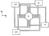
提唱されている解決策の1つは、液体供給システムを用いて、液体供給システムが、投影システムの最終要素と基板との間の基板の局所領域のみに液体を供給するようにすることである(基板は一般に、投影システムの最終要素より大きい表面積を有する)。このように構成することを提唱している1つの方法がPCT出願WO99/49504に開示されており、その全体を参照によって本明細書に援用する。図2及び図3に示すように、液体は少なくとも1つの入口INによって、好ましくは最終要素に対する基板の移動方向に沿って基板上に供給され、投影システムの下を通過した後、少なくとも1つの出口OUTによって除去される。すなわち、基板が要素の下を−X方向に走査される際に、液体は要素の+X側に供給され、−X側で取り出される。図2は、液体が入口INを介して供給され、低圧源に接続された出口OUTによって要素の反対側で取り出される配置を概略的に示している。図2の例では、液体が最終要素に対する基板の移動方向に沿って供給されているが、このようにする必要はない。最終要素の周りに配置される入口及び出口は、様々な向き及び数とすることが可能であり、両側に出口を備えた4組の入口を最終要素の周りに規則正しいパターンで設けた一実施例を図3に示す。 One proposed solution is to use a liquid supply system so that the liquid supply system supplies liquid only to a local area of the substrate between the final element of the projection system and the substrate. (The substrate generally has a larger surface area than the final element of the projection system). One method that has been proposed to do so is disclosed in PCT application WO 99/49504, which is hereby incorporated by reference in its entirety. As shown in FIGS. 2 and 3, the liquid is supplied onto the substrate by at least one inlet IN, preferably along the direction of movement of the substrate relative to the final element, and after passing under the projection system, at least one outlet. Removed by OUT. That is, as the substrate is scanned under the element in the -X direction, liquid is supplied to the + X side of the element and removed on the -X side. FIG. 2 schematically shows an arrangement in which liquid is supplied via an inlet IN and taken out on the opposite side of the element by an outlet OUT connected to a low pressure source. In the example of FIG. 2, the liquid is supplied along the direction of movement of the substrate relative to the final element, but this need not be the case. The inlets and outlets arranged around the final element can be of various orientations and numbers, and one embodiment in which four sets of inlets with outlets on both sides are provided in a regular pattern around the final element Is shown in FIG.
リソグラフィ装置の性能を維持するために、放射源、照明系及び投影システムの性能の定期的な測定を行うことが可能であり、したがって、装置のいずれかの部分の性能が低下した場合には、再較正など補正手段を講じることができる。結像に影響を及ぼす可能性のある1つ又は複数のパラメータを測定するために、装置の光路内に1つ又は複数のセンサを設けることができるが、きわめて重要ないくつかの場合では、基板レベルで直接、空中画像の測定を行うことが望ましい。そうした測定は製造時の露光と並行して同時に実施することはできず、したがって定期的に停止時間が設けられ、装置の生産性が低下することになる。 In order to maintain the performance of the lithographic apparatus, it is possible to make periodic measurements of the performance of the radiation source, the illumination system and the projection system, and thus if the performance of any part of the apparatus is reduced, Correction means such as recalibration can be taken. One or more sensors can be provided in the optical path of the device to measure one or more parameters that can affect imaging, but in some very important cases, the substrate It is desirable to perform aerial image measurements directly at the level. Such a measurement cannot be performed simultaneously in parallel with the exposure at the time of manufacture. Therefore, a stop time is regularly provided, and the productivity of the apparatus is lowered.
したがって、例えば、生産性を低下させることなく、基板水準での測定を行うことのできるリソグラフィ装置が提供されると有利であろう。 Thus, for example, it would be advantageous to provide a lithographic apparatus that can perform substrate level measurements without reducing productivity.
本発明の一観点によれば、パターンの付与された放射ビームを基板に投影するリソグラフィ装置に用いるための位置決め装置において、位置決め装置が、第1のテーブルと第2のテーブルとを含み、
第1のテーブルが、該第1のテーブルをパターンの付与された放射ビームの経路内及び経路外へ移動させるように構成された第1の位置決めシステムに接続されて、基板を保持するように構成されており、
第2のテーブルが、第1のテーブルをパターンの付与された放射ビームの経路外へ移動させる際に、該第2のテーブルをパターンの付与された放射ビームの経路内に位置決めするように構成された第2の位置決めシステムに接続されて、基板を保持するようには構成されていない位置決め装置が提供される。According to an aspect of the present invention, in a positioning apparatus for use in a lithographic apparatus that projects a patterned radiation beam onto a substrate, the positioning apparatus includes a first table and a second table,
A first table is connected to a first positioning system configured to move the first table in and out of the path of the patterned beam of radiation and configured to hold the substrate Has been
The second table is configured to position the second table in the path of the patterned radiation beam as the first table is moved out of the path of the patterned radiation beam. A positioning device connected to the second positioning system and not configured to hold the substrate is provided.
本発明の一観点によれば、
基板を保持するように構成された基板テーブルと、
パターンの付与されたビームを基板に投影するように構成された投影システムと、
基板テーブルに接続され、基板テーブルをパターンの付与された放射ビームの経路内及び経路外へ移動させるように構成された第1の位置決めシステムと、
基板を保持するようには構成されておらず、パターンの付与された放射ビームの特性を検知するように構成されたセンサを有するセンサ・テーブルと、
第1のテーブルをパターンの付与された放射ビームの経路外へ移動させる際に、センサ・テーブルをパターンの付与された放射ビームの経路内に位置決めするように構成された第2の位置決めシステムとを有するリソグラフィ装置が提供される。According to one aspect of the present invention,
A substrate table configured to hold a substrate;
A projection system configured to project a patterned beam onto a substrate;
A first positioning system connected to the substrate table and configured to move the substrate table in and out of the path of the patterned radiation beam;
A sensor table having a sensor not configured to hold a substrate and configured to sense a characteristic of a patterned radiation beam;
A second positioning system configured to position the sensor table within the path of the patterned radiation beam when moving the first table out of the path of the patterned radiation beam; A lithographic apparatus is provided.
本発明の他の観点によれば、
パターンの付与された放射ビームを、テーブルに保持された基板に投影する段階と、
テーブルをパターンの付与された放射ビームの経路外へ移動させる段階と、
センサをパターンの付与された放射ビームの経路内へ移動させる段階およびビームの特性を測定する段階とを含み、
センサを移動させる段階および特性を測定する段階が、少なくとも部分的に、テーブルを移動させる段階と同時に行われるデバイス製造方法が提供される。According to another aspect of the invention,
Projecting a patterned beam of radiation onto a substrate held on a table;
Moving the table out of the path of the patterned radiation beam;
Moving the sensor into the path of the patterned radiation beam and measuring the characteristics of the beam;
A device manufacturing method is provided in which the steps of moving the sensor and measuring the characteristics are performed at least in part simultaneously with the step of moving the table.
次に本発明の実施例を、添付の概略図を参照して例示のみの目的で説明するが、図中において同じ参照記号は同じ部品を指すものであることに留意されたい。 Embodiments of the present invention will now be described, by way of example only, with reference to the accompanying schematic drawings in which like reference numerals refer to like parts.
図1は、本発明の一実施例によるリソグラフィ装置を概略的に示している。この装置は、
放射ビームPB(例えば、UV放射又はDUV放射)を調節するように構成された照明系(照明器)ILと、
パターン形成装置(例えばマスク)MAを支持するように構成された支持構造体(例えばマスク・テーブル)MTであって、あるパラメータに従ってパターン形成装置を正確に位置決めするように構成された第1の位置決め装置PMに接続された支持構造体MTと、
基板(例えばレジスト塗布ウェハ)Wを保持するように構成された基板テーブル(例えばウェハ・テーブル)WTであって、あるパラメータに従って基板を正確に位置決めするように構成された第2の位置決め装置PWに接続された基板テーブルWTと、
パターン形成装置MAによって放射ビームPBに与えられたパターンを、基板Wの(例えば1つ又は複数のダイを含む)ターゲット部分Cに投影するように構成された投影システム(例えば屈折投影レンズ系)PLとを有している。FIG. 1 schematically depicts a lithographic apparatus according to one embodiment of the invention. This device
An illumination system (illuminator) IL configured to condition a radiation beam PB (eg, UV radiation or DUV radiation);
A support structure (eg, mask table) MT configured to support a patterning device (eg, mask) MA, a first positioning configured to accurately position the patterning device according to certain parameters A support structure MT connected to the device PM;
A substrate table (eg, wafer table) WT configured to hold a substrate (eg, resist coated wafer) W, to a second positioning device PW configured to accurately position the substrate according to certain parameters A connected substrate table WT;
A projection system (eg a refractive projection lens system) PL configured to project the pattern imparted to the radiation beam PB by the patterning device MA onto a target portion C (eg including one or more dies) of the substrate W. And have.
照明系は、放射の方向付け、成形又は制御のための屈折式、反射式、磁気式、電磁式、静電式又は他の種類の光学要素、或いはそれらの任意の組み合わせなど、様々な種類の光学要素を含むことができる。 The illumination system can be of various types, including refractive, reflective, magnetic, electromagnetic, electrostatic or other types of optical elements, or any combination thereof for directing, shaping or controlling radiation. An optical element can be included.
支持構造体は、パターン形成装置の向き、リソグラフィ装置の設計、並びに、例えばパターン形成装置が真空環境に保持されているかどうかなど他の条件によって決まる方法でパターン形成装置を保持する。支持構造体は、機械式、真空式、静電式又は他のクランプ技術を用いてパターン形成装置を保持することができる。支持構造体を、例えば枠台(フレーム)又はテーブルとすることが可能であり、これらは必要に応じて固定することも移動させることもできる。支持構造体は、パターン形成装置が、例えば投影システムに対して、所望の位置にあることを保証できる。本明細書中の「レチクル」又は「マスク」という用語の使用はいずれも、「パターン形成装置」というより一般的な用語と同義であると考えられる。 The support structure holds the patterning device in a manner that depends on the orientation of the patterning device, the design of the lithographic apparatus, and other conditions, such as for example whether or not the patterning device is held in a vacuum environment. The support structure can hold the patterning device using mechanical, vacuum, electrostatic or other clamping techniques. The support structure can be a frame or a table, for example, which can be fixed or moved as required. The support structure can ensure that the patterning device is at a desired position, for example with respect to the projection system. Any use of the terms “reticle” or “mask” herein may be considered synonymous with the more general term “patterning device.”
本明細書で使用する「パターン形成装置」という用語は、基板のターゲット部分にパターンを形成するためなど、放射ビームの断面にパターンを与えるために用いることのできる任意の装置を指すものとして広く解釈すべきである。例えばパターンが位相シフト・フィーチャ、又はいわゆるアシスト・フィーチャを含む場合には、放射ビームに与えられるパターンが、基板のターゲット部分における所望のパターンと厳密に一致しない可能性があることに留意すべきである。一般に、放射ビームに与えられるパターンは、集積回路などターゲット部分に作製されるデバイスの特定の機能層に対応している。 As used herein, the term “patterning device” is broadly interpreted as referring to any device that can be used to pattern a cross section of a radiation beam, such as to form a pattern on a target portion of a substrate. Should. It should be noted that the pattern imparted to the radiation beam may not exactly match the desired pattern in the target portion of the substrate, for example if the pattern includes phase shift features, or so-called assist features. is there. In general, the pattern imparted to the radiation beam will correspond to a particular functional layer in a device being created in the target portion, such as an integrated circuit.
パターン形成装置は、透過式でも反射式でもよい。パターン形成装置の例には、マスク、プログラム可能ミラー配列(アレイ)及びプログラム可能LCDパネルが含まれる。マスクはリソグラフィの分野では周知であり、それにはバイナリ・マスク、交互位相シフト・マスク(alternating PSM)及び減衰位相シフト・マスク(attenuated PSM)などのマスク・タイプ、並びに様々なハイブリッド型のマスク・タイプが含まれる。プログラム可能ミラー配列の例は、小さいミラーのマトリクス(行列)状の配列を使用するものであり、入射する放射ビームを異なる方向に反射するように、それぞれのミラーを別々に傾斜させることができる。傾斜したミラーは、ミラーのマトリクスによって反射される放射ビームにパターンを与える。 The pattern forming apparatus may be transmissive or reflective. Examples of patterning devices include masks, programmable mirror arrays and programmable LCD panels. Masks are well known in the field of lithography, and include mask types such as binary masks, alternating phase shifted masks (alternating PSMs) and attenuated phase shift masks (attenuated PSMs), as well as various hybrid mask types. Is included. An example of a programmable mirror array is one that uses a matrix-like array of small mirrors, where each mirror can be tilted separately to reflect the incoming radiation beam in different directions. The tilted mirror imparts a pattern to the radiation beam reflected by the mirror matrix.
本明細書で使用する「投影システム」という用語は、適宜、使用される露光放射向け、又は浸漬液の使用や真空の使用など他の要素向けの屈折式、反射式、反射屈折式、磁気式、電磁式及び静電式の光学系、又はそれらの任意の組み合わせを含めて、任意の種類の投影システムを包含するものとして広く解釈すべきである。本明細書中の「投影レンズ」という用語の使用はいずれも、「投影システム」というより一般的な用語と同義であると考えられる。 As used herein, the term “projection system” refers to refractive, reflective, catadioptric, magnetic, as appropriate, for the exposure radiation used, or for other elements such as the use of immersion liquid or vacuum. Should be interpreted broadly to encompass any type of projection system, including electromagnetic and electrostatic optics, or any combination thereof. Any use of the term “projection lens” herein may be considered as synonymous with the more general term “projection system”.
本明細書で図示する装置は、(例えば透過性マスクを使用する)透過式のものである。或いは、装置は(例えば先に言及した種類のプログラム可能ミラー配列を使用、或いは反射性マスクを使用する)反射式のものでもよい。 The apparatus illustrated herein is of a transmissive type (eg, using a transmissive mask). Alternatively, the device may be of a reflective type (for example using a programmable mirror array of the type mentioned above or using a reflective mask).
リソグラフィ装置は、2(デュアル・ステージ)又は3以上の基板テーブル(及び/又は2以上の支持構造体)を有する種類のものでもよい。こうした「マルチ・ステージ」装置では、追加のテーブルを並行して用いてもよく、或いは1つ又は複数のテーブル上で予備工程を実施し、それと同時に1つ又は複数の他のテーブルを露光に用いてもよい。 The lithographic apparatus may be of a type having two (dual stage) or more substrate tables (and / or two or more support structures). In such a “multi-stage” apparatus, additional tables may be used in parallel, or a preliminary process is performed on one or more tables and at the same time one or more other tables are used for exposure. May be.
図1を参照すると、照明器ILは放射源SOから放射ビームを受け取る。例えば放射源がエキシマ・レーザーの場合、放射源とリソグラフィ装置とを別々の構成要素にできる。その場合には、放射源がリソグラフィ装置の一部を形成するとは考えられず、放射ビームは、例えば適切な指向性ミラー及び/又はビーム拡大器(エキスパンダ)を有するビーム送出システムBDを用いて、放射源SOから照明器ILへ送られる。他の場合、例えば放射源が水銀ランプの場合には、放射源をリソグラフィ装置の一体部分とできる。放射源SO及び照明器ILを、必要であればビーム送出システムBDと共に、放射システムと呼ぶことがある。 Referring to FIG. 1, the illuminator IL receives a radiation beam from a radiation source SO. For example, if the source is an excimer laser, the source and the lithographic apparatus can be separate components. In that case, the radiation source is not considered to form part of the lithographic apparatus, and the radiation beam is used, for example, with a beam delivery system BD having a suitable directional mirror and / or beam expander (expander). , From the radiation source SO to the illuminator IL. In other cases the source may be an integral part of the lithographic apparatus, for example when the source is a mercury lamp. The radiation source SO and the illuminator IL may be referred to as a radiation system, together with a beam delivery system BD if necessary.
照明器ILは、放射ビームの角強度分布を調整するための調整装置AMを含むことができる。一般に、照明器の瞳面内における強度分布の少なくとも外側及び/又は内側の半径方向範囲(それぞれ一般にσ−アウタ(σ−outer)、σ−インナ(σ−inner)と呼ばれる)を調整することができる。さらに照明器ILは、積算器INやコンデンサCOなど他の様々な構成要素を含むことができる。照明器を用いて、所望される均一性及び強度分布をその断面に有するように放射ビームを調節できる。 The illuminator IL may include an adjusting device AM for adjusting the angular intensity distribution of the radiation beam. In general, adjusting at least the outer and / or inner radial extent (commonly referred to as σ-outer and σ-inner, respectively) of the intensity distribution in the pupil plane of the illuminator. it can. In addition, the illuminator IL may include various other components such as an integrator IN and a capacitor CO. An illuminator can be used to adjust the radiation beam to have the desired uniformity and intensity distribution in its cross section.
放射ビームPBは、支持構造体(例えばマスク・テーブルMT)に保持されているパターン形成装置(例えばマスクMA)に入射し、パターン形成装置によって放射ビームPBにパターンが付与される。パターン形成装置MAを通過した放射ビームPBは、ビームを基板Wのターゲット部分Cに集束させる投影システムPLを通過する。第2の位置決め装置PW及び位置センサIF(例えば干渉測定装置、リニア・エンコーダ又は容量センサ)を用いて、基板テーブルWTを、例えば異なるターゲット部分Cを放射ビームPBの経路内に位置決めするように、正確に移動させることができる。同様に、第1の位置決め装置PM及び(図1には明示されていない)他の位置センサを用いて、例えばマスク・ライブラリから機械的に取り出した後、又は走査中に、パターン形成装置MAを放射ビームPBの経路に対して正確に位置決めすることができる。一般に、支持構造体MTの移動は、第1の位置決め装置PMの一部を形成する長ストローク・モジュール(粗い位置決め)及び短ストローク・モジュール(細かい位置決め)を用いて実現される。同様に、基板テーブルWTの移動は、第2の位置決め装置PWの一部を形成する長ストローク・モジュール及び短ストローク・モジュールを用いて実現される。(スキャナではなく)ステッパの場合には、支持構造体MTを短ストローク・アクチュエータに接続するだけでもよく、又は固定してもよい。パターン形成装置MA及び基板Wは、パターン形成装置位置調整用マークM1、M2、及び基板位置調整用マークP1、P2を用いて位置を調整できる。図示した基板位置調整用マークは専用のターゲット部分を占めているが、それらをターゲット部分同士の間の空間に配置することもできる(これらはスクライブレーン位置調整用マークとして知られている)。同様に、パターン形成装置MAに2つ以上のダイを設ける場合には、パターン形成装置位置調整用マークをダイ同士の間に配置してもよい。 The radiation beam PB is incident on a pattern forming apparatus (eg, mask MA) held on a support structure (eg, mask table MT), and the pattern is applied to the radiation beam PB by the pattern forming apparatus. The radiation beam PB that has passed through the patterning device MA passes through a projection system PL that focuses the beam onto a target portion C of the substrate W. Using the second positioning device PW and the position sensor IF (for example an interference measuring device, linear encoder or capacitive sensor), the substrate table WT is positioned, for example, a different target portion C in the path of the radiation beam PB, It can be moved accurately. Similarly, using the first positioning device PM and other position sensors (not explicitly shown in FIG. 1), for example after mechanical removal from the mask library or during scanning, the patterning device MA is It can be accurately positioned with respect to the path of the radiation beam PB. In general, the movement of the support structure MT is realized using a long stroke module (coarse positioning) and a short stroke module (fine positioning) which form part of the first positioning device PM. Similarly, movement of the substrate table WT is realized using a long stroke module and a short stroke module that form part of the second positioning device PW. In the case of a stepper (not a scanner), the support structure MT may simply be connected to a short stroke actuator or may be fixed. The positions of the pattern forming apparatus MA and the substrate W can be adjusted using the pattern forming apparatus position adjusting marks M1, M2 and the substrate position adjusting marks P1, P2. The substrate position adjustment marks shown occupy dedicated target portions, but they can also be placed in the space between the target portions (these are known as scribe lane position adjustment marks). Similarly, when two or more dies are provided in the pattern forming apparatus MA, a pattern forming apparatus position adjustment mark may be arranged between the dies.
図示した装置は、以下のモードの少なくとも1つで使用することができる。
(1)ステップ・モードでは、放射ビームに与えられたパターン全体を1回でターゲット部分Cに投影する間、支持構造体MT及び基板テーブルWTを本質的に静止した状態に保つ(すなわち、ただ1回の静止露光)。次いで、異なるターゲット部分Cを露光できるように、基板テーブルWTをX及び/又はY方向に移動させる。ステップ・モードでは、露光場(露光フィールド)の最大サイズによって1回の静止露光で結像されるターゲット部分Cのサイズが制限される。
(2)走査モードでは、放射ビームに与えられたパターンをターゲット部分Cに投影する間、支持構造体MT及び基板テーブルWTを同期して走査する(すなわち、ただ1回の動的露光)。支持構造体MTに対する基板テーブルWTの速度及び方向は、投影システムPLの拡大(縮小)率、及び像の反転特性によって決定できる。走査モードでは、露光フィールドの最大サイズによって1回の動的露光におけるターゲット部分の(非走査方向の)幅が制限され、走査移動の長さによってターゲット部分の(走査方向の)高さが決定される。
(3)他のモードでは、放射ビームに与えられたパターンをターゲット部分Cに投影する間、プログラム可能なパターン形成装置を保持しながら支持構造体MTを本質的に静止した状態に保ち、基板テーブルWTを移動又は走査させる。このモードでは、一般にパルス式の放射源が使用され、基板テーブルWTが移動するたびに、又は走査中の連続する放射パルスの合間に、プログラム可能なパターン形成装置が必要に応じて更新される。この動作モードは、先に言及した種類のプログラム可能ミラー配列などの、プログラム可能なパターン形成装置を利用するマスクレス・リソグラフィに簡単に適用できる。The depicted apparatus can be used in at least one of the following modes:
(1) In step mode, the support structure MT and the substrate table WT remain essentially stationary (ie, only 1) while the entire pattern imparted to the radiation beam is projected onto the target portion C in one go. Times of static exposure). The substrate table WT is then moved in the X and / or Y direction so that a different target portion C can be exposed. In the step mode, the maximum size of the exposure field (exposure field) limits the size of the target portion C imaged in one still exposure.
(2) In the scanning mode, the support structure MT and the substrate table WT are scanned synchronously while a pattern imparted to the radiation beam is projected onto the target portion C (ie, only one dynamic exposure). The speed and direction of the substrate table WT relative to the support structure MT can be determined by the magnification (reduction) rate of the projection system PL and the reversal characteristics of the image. In scan mode, the maximum size of the exposure field limits the width (in the non-scan direction) of the target portion in a single dynamic exposure, and the length of the scan movement determines the height of the target portion (in the scan direction). The
(3) In other modes, the substrate structure is held essentially stationary while holding the programmable patterning device while projecting the pattern imparted to the radiation beam onto the target portion C. Move or scan the WT. In this mode, a pulsed radiation source is typically used, and the programmable patterning device is updated as needed each time the substrate table WT is moved or between successive radiation pulses during scanning. This mode of operation can be readily applied to maskless lithography that utilizes programmable patterning device, such as a programmable mirror array of a type as referred to above.
前記の使用モードの組み合わせ及び/又は変形形態、或いは全く異なる使用モードを採用することもできる。 Combinations and / or variations on the above described modes of use or entirely different modes of use may also be employed.
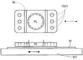
局所的な液体供給システムを用いた他の浸漬リソグラフィ装置の解決策を図4に示す。液体は、投影システムPLの両側の2つの溝状入口INによって供給され、入口INの半径方向外側に配置された複数の別々の出口OUTによって除去される。入口IN及び出口OUTは、投影ビームがそれを通して投影される孔を中央に有する板に配置することができる。液体は、投影システムPLの一方の側で一方の溝状入口INによって供給され、投影システムPLのもう一方の側で複数の別々の出口OUTによって除去されて、投影システムPLと基板Wとの間に薄膜状の液体の流れを生じさせる。入口INと出口OUTのどの組み合わせを使用するかの選択は、基板Wの移動方向によって決めることができる(入口INと出口OUTの他の組み合わせは作動させない)。 Another immersion lithographic apparatus solution using a localized liquid supply system is shown in FIG. The liquid is supplied by two grooved inlets IN on both sides of the projection system PL and is removed by a plurality of separate outlets OUT arranged radially outside the inlet IN. The inlet IN and outlet OUT can be arranged in a plate having a central hole through which the projection beam is projected. Liquid is supplied by one grooved inlet IN on one side of the projection system PL and removed by a plurality of separate outlets OUT on the other side of the projection system PL, between the projection system PL and the substrate W. This causes a thin liquid flow. The selection of which combination of inlet IN and outlet OUT to use can be determined by the direction of movement of the substrate W (other combinations of inlet IN and outlet OUT are not activated).
提唱されている局所的な液体供給システムを用いた浸漬リソグラフィの他の解決策は、投影システムの最終要素と基板テーブルとの間の空間の少なくとも一部の境界に沿って延びる液体閉じ込め構造体を備えた液体供給システムを提供することである。液体閉じ込め構造体は、XY平面内では投影システムに対して実質的に静止しているが、Z方向(光軸の方向)にはある程度の相対移動が可能である。液体閉じ込め構造体と基板表面との間には、シール(密封)が形成される。一実施例では、シールはガス・シールなどの非接触シールである。このようなガス・シールを備えたシステムが、米国特許出願第10/705783号に開示されており、その全体を参照によって本明細書に援用する。 Other proposed solutions for immersion lithography using a localized liquid supply system include a liquid confinement structure that extends along the boundary of at least a portion of the space between the final element of the projection system and the substrate table. A liquid supply system is provided. The liquid confinement structure is substantially stationary with respect to the projection system in the XY plane, but can move to some extent in the Z direction (the direction of the optical axis). A seal is formed between the liquid confinement structure and the substrate surface. In one embodiment, the seal is a contactless seal such as a gas seal. A system with such a gas seal is disclosed in US patent application Ser. No. 10 / 705,783, which is incorporated herein by reference in its entirety.
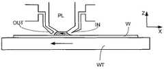
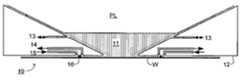
図5は、本発明の一実施例による(浸漬フード又はシャワーヘッドと呼ばれることもある)液体閉じ込め構造体を有する液体供給システムを示している。特に図5は、液体を閉じ込めて基板表面と投影システムの最終要素との間の空間を満たすように、投影システムの画像領域(イメージ・フィールド)の周りに基板に対する非接触シールを形成する貯水部(リザーバ)10の配置を示している。投影システムPLの最終要素の下に配置され、それを囲む液体閉じ込め構造体12が、貯水部を形成している。液体は、投影システムの下、及び液体閉じ込め構造体12の内側の空間に導入される。液体閉じ込め構造体12は投影システムの最終要素の少し上方に延びており、液体の高さが最終要素より上方まで上昇して、その結果、液体の緩衝体が形成される。液体閉じ込め構造体12の上端は、好ましくは投影システム又はその最終要素の形に厳密に一致した内側周縁を有し、例えばそれを円形にすることができる。底部は、内側周縁が画像領域の形に厳密に一致し、例えば長方形にすることができるが、必ずしもそうである必要はない。 FIG. 5 illustrates a liquid supply system having a liquid confinement structure (sometimes referred to as an immersion hood or showerhead) according to one embodiment of the present invention. In particular, FIG. 5 shows a reservoir that forms a contactless seal to the substrate around the image area of the projection system so as to confine liquid and fill the space between the substrate surface and the final element of the projection system. The arrangement of (reservoir) 10 is shown. A
液体は、液体閉じ込め構造体12の底部と基板Wの表面との間で、ガス・シール16によって貯水部に閉じ込められる。ガス・シールは、加圧下で入口15を通して、液体閉じ込め構造体12と基板との間の隙間に供給され、出口14を通して取り出されるガス、例えば空気、合成空気、N2、不活性ガスによって形成される。ガス入口15に対する加圧力、出口14に対する真空度、及び隙間の形状は、液体を閉じ込める内側への高速ガス流れが存在するように構成される。液体を収容するために、単に液体及び/又はガスを除去する出口など他の種類のシールを用いることもできることが、当業者には理解されよう。The liquid is confined in the reservoir by a
図6は、本発明の一実施例による基板ステージの配置を示している。この実施例は、基板レベルに露光ステーションES及び測定ステーションMSの2つのステーションの存在する、いわゆるデュアル・ステージ装置である。例えば露光前に基板の特徴を明らかにするため、或いは露光が適切に行われたことを検証するために、測定ステーションで様々な測定が行われる間、露光ステーションでは基板が露光される。測定ステーションに1つ又は複数のセンサを設けて測定を行うことも可能であり、測定ステーションに設けることのできるセンサの型の例には、露光前に基板の高さ地図を作成するための水準(レベル)センサLS、基板の1つ又は複数の位置調整用マークの位置を測定するための位置調整用センサAS、及び露光された基板の潜像を調べるためのスキャタロメータSMが含まれる。測定ステーションで基板を基板テーブルへ装着(ロード)及び取り除く(アンロード)ために、ロード/アンロード用のロボット(図示せず)も設けられる。このようなデュアル・ステージ装置では、1つの基板を露光している間、以前に露光された基板を測定し、且つ/又は次に露光される基板を予め測定することができる。したがって、デュアル・ステージ装置により、測定および露光の両工程を単一のステーションで実施するシングル・ステージ装置と比べて生産性を向上させることができる。 FIG. 6 shows an arrangement of substrate stages according to an embodiment of the present invention. This embodiment is a so-called dual stage apparatus in which two stations of an exposure station ES and a measurement station MS exist at the substrate level. The substrate is exposed at the exposure station during various measurements at the measurement station, for example to characterize the substrate prior to exposure or to verify that the exposure was properly performed. One or more sensors may be provided at the measurement station to perform measurements, and examples of sensor types that can be provided at the measurement station include levels for creating a substrate height map prior to exposure. A (level) sensor LS, a position adjustment sensor AS for measuring the position of one or more position adjustment marks on the substrate, and a scatterometer SM for examining the latent image of the exposed substrate are included. A loading / unloading robot (not shown) is also provided for loading (loading) and removing (unloading) the substrate from the substrate table at the measuring station. In such a dual stage apparatus, while exposing one substrate, a previously exposed substrate can be measured and / or a next exposed substrate can be pre-measured. Therefore, the dual stage apparatus can improve productivity as compared with a single stage apparatus in which both the measurement and exposure processes are performed in a single station.
図6を参照すると、装置は、2つのH型駆動装置(H−drive)を有する位置決めシステムPWによって位置決めされる2つの基板テーブルWT1、WT2を有し、H型駆動装置のそれぞれが、基板テーブルを一方のステーションの範囲内に位置決めするようになっている。図7に示すように、一実施例によれば、露光処理の終わりに、2つの基板テーブルWT1、WT2は2つのステーション間の境界に位置決めされ、位置決めシステムPWから切り離される。次いで、H型駆動装置はそれぞれ、他方のH型駆動装置によって解放された基板テーブルを取り上げる。この処理は、チャック交換又はテーブル交換と呼ばれることがある。したがって、測定ステーションで事前の測定が行われたばかりの基板W2を露光ステーションで露光することが可能になり、また露光されたばかりの基板W1を測定ステーションで測定及び/又はアンロードすることが可能になる。別の配置は、2つの測定ステーション及び2つの基板テーブルを有するが、露光ステーションは1つだけである。各基板テーブルは、それ自体の測定ステーション及び露光ステーションを含めた領域を有する駆動システムによって位置決めされ、したがって、位置決めシステムの部分間でのテーブル交換は行われない。しかし、一方のテーブルを露光ステーションの外へ移動させ、他方を露光ステーションの中へ移動させる間には、テーブル交換と呼ぶこともできる段階が依然として存在する。 Referring to FIG. 6, the apparatus has two substrate tables WT1, WT2 positioned by a positioning system PW having two H-type drives (H-drive), each of the H-type drives being a substrate table. Is positioned within the range of one station. As shown in FIG. 7, according to one embodiment, at the end of the exposure process, the two substrate tables WT1, WT2 are positioned at the boundary between the two stations and disconnected from the positioning system PW. Each H drive then picks up the substrate table released by the other H drive. This process is sometimes called chuck exchange or table exchange. Therefore, it becomes possible to expose the substrate W2 that has been previously measured at the measurement station at the exposure station, and to measure and / or unload the substrate W1 that has just been exposed at the measurement station. . Another arrangement has two measurement stations and two substrate tables, but only one exposure station. Each substrate table is positioned by a drive system having an area that includes its own measuring station and exposure station, so that table exchange between parts of the positioning system is not performed. However, there is still a stage that can be referred to as table exchange while moving one table out of the exposure station and moving the other into the exposure station.
例えばシャワーヘッド型のものなど、局所的な液体供給システムを備えた浸漬リソグラフィ装置では、テーブル交換処理の間に浸漬液が装置の他の部分へ漏出することを防ぐために、液体供給システムが止められ、或いは閉鎖面が設けられる。一実施例では、基板テーブルの陥凹部に閉鎖板を設けることが可能であり、閉鎖板を液体閉じ込め構造体IHによって陥凹部から取り上げた後、基板テーブルを投影システムPLの下から外へ移動させる。 In an immersion lithographic apparatus with a local liquid supply system, for example of a showerhead type, the liquid supply system is stopped to prevent the immersion liquid from leaking to other parts of the apparatus during the table exchange process. Alternatively, a closure surface is provided. In one embodiment, it is possible to provide a closure plate in the recess of the substrate table, after the closure plate is picked up from the recess by the liquid confinement structure IH, the substrate table is moved out from under the projection system PL. .
本発明の一実施例では、位置決めシステム22、23と共に第3のテーブル21が設けられ、位置決めシステム22、23は、第3のテーブルを投影システムPL及び液体閉じ込め構造体IHの下に位置決めできるようになっている。第3のテーブル21及び位置決めシステム22、23は共に、第3のステージ20を形成することができる。第3のテーブル21により、少なくとも2つの機能を実現することができる。第1に、基板テーブルWT1、WT2を取り除く際、第3のテーブル21は液体閉じ込め構造体IHの底部に閉じ込め用の面を形成して、浸漬液が装置の他の部分へ漏出することを防ぐことができる。第2に、第3のテーブル21は、投影システムPLによって投影された空中画像の測定を行うための1つ又は複数のセンサを含む、センサ・ユニット24を有することができる。センサ・ユニットに含めることのできるセンサの種類には、透過イメージ・センサ(TIS)、エネルギー・センサ、偏光センサ、及びシヤリング干渉計センサが含まれる(例えば、2004年11月16日出願の米国特許出願第10/988845号を参照。この文献全体を参照によって本明細書に援用する)。一実施例では、センサ・ユニット24はシヤリング干渉計センサを含み、それを用いて投影システムPLにおける収差の特徴を明らかにすると有利になることがあるが、それは、そうしたセンサによって行われる測定は比較的長い時間をかけて行われ、結像性能にとって重要であるためである。 In one embodiment of the present invention, a third table 21 is provided along with
センサ・ユニットを第3のテーブル21に設けると、基板テーブルの交換の合間を利用することにより、生産性を低下させずに(1つ又は複数の)センサを用いて基板の水準での測定を行うことが可能になる。したがって、停止時間をかなり短縮することができる。所望される(1つ又は複数の)測定(例えば較正に必要な測定)に基板テーブル交換より長い時間がかかる場合には、その(1つ又は複数の)測定を複数の部分に分割し、複数の基板テーブルの交換段階の間に、おそらくはその段階を通じて測定間で変化する可能性のある要素を考慮するための変更を加えて、実施できることに留意すべきである。別法として或いは追加として、交換段階を(1つ又は複数の)測定に適合させるように延長することも可能であり、1つ又は複数の場合には生産性はある程度損なわれるが、それは、測定全体を基板露光の停止時間中に実施した場合ほどではない。 When the sensor unit is provided on the third table 21, it is possible to measure at the substrate level using the sensor (s) without reducing productivity by using the interval between substrate table replacements. It becomes possible to do. Therefore, the stop time can be considerably shortened. If the desired measurement (s) takes longer than replacing the substrate table (eg the measurement required for calibration), divide the measurement (s) into parts and It should be noted that during the substrate table exchange phase, changes may be made, possibly to account for factors that may change between measurements throughout the phase. Alternatively or additionally, the exchange phase can be extended to match the measurement (s), and in one or more cases, the productivity is impaired to some extent, Not as much as if the whole was done during substrate exposure downtime.
複数の光学要素を含む偏光センサは非常にかさばる可能性があり、基板テーブルWT1、WT2の一方又は両方に対して適合させるのは難しい場合があるため、第3のテーブルにセンサ・ユニットの一部として偏光センサを設けることによっても利点が得られる。 A polarization sensor that includes multiple optical elements can be very bulky and can be difficult to adapt to one or both of the substrate tables WT1, WT2, so a third table is part of the sensor unit An advantage can also be obtained by providing a polarization sensor.
例えば第3のテーブル21に設けられるセンサの種類によっては、位置決めシステム22、23は、図7に示すように、例えば基板テーブルWT1、WT2を取り除くのと同期して、第3のテーブル21を投影システムPLの下に位置決めするための長ストローク駆動モジュールを有するだけでもよい。これは、第3のテーブル21の位置決めシステム、及び基板テーブルWT1、WT2の位置決めシステムに接続された制御装置CSによる制御の下で実施することができる。測定を行うために、センサがより正確な位置決め及び/又は走査を必要とする場合には、任意選択で短ストローク駆動モジュールを含めることができる。2つ以上のセンサを設ける場合には、同時に動作するように各センサを露光フィールドの領域内に収めることが可能であり、或いはそれが不都合である場合には、位置決めシステムを、異なるセンサを連続的に露光フィールド内に位置決めするように構成することができる。 For example, depending on the type of sensor provided on the third table 21, the
本発明をデュアル・ステージの浸漬式リソグラフィ装置に関して説明してきたが、本発明は、浸漬式ではない装置と共に用いることもでき、また基板のロード及びアンロード動作のために基板テーブルを投影システムの下から外へ移動させるシングル・ステージ装置と共に用いることもできることに留意すべきである。第3のテーブルは、例えばセンサに加えて、或いはセンサの代わりに、投影システムの最終要素を清浄するように構成された清浄装置など他の装置を備えることもできる。清浄装置は、ガス、電気粒子(electric particle)、レーザー、又は投影システムを清浄するための他の機構を用いることができる。第3のテーブルを、センサや他の装置を備えていない浸漬リソグラフィ装置に用いることも可能であり、むしろ単に、例えばテーブル交換及び/又は基板のロードとアンロードとの間、液体供給システムに対して閉じ込め用の面を設けるために用いてもよい。 Although the present invention has been described with reference to a dual stage immersion lithography apparatus, the present invention can also be used with non-immersion apparatus and a substrate table under the projection system for substrate loading and unloading operations. It should be noted that it can also be used with a single stage device that moves out of the room. The third table may also comprise other devices, such as a cleaning device configured to clean the final elements of the projection system, for example in addition to or instead of the sensors. The cleaning device can use a gas, an electrical particle, a laser, or other mechanism for cleaning the projection system. The third table can also be used in an immersion lithographic apparatus that is not equipped with sensors or other devices, but rather simply for the liquid supply system, for example during table exchange and / or substrate loading and unloading. And may be used to provide a confinement surface.
さらに、(浸漬能力の有無に関わらず)複数(例えば2)ステージのリソグラフィ装置は、1つの露光ステーション及び2つ以上の測定ステーションを有することができる。この配置では、例えば測定ステーションを露光ステーションの反対側に設けることが可能であり、そこで投影システムを位置決めし、次いで2つの基板テーブルを、2つの測定ステーションと露光ステーションとの間で往復させることができる。一実施例では、第1の基板テーブルを露光ステーションと第1の測定ステーションとの間で往復させ、第2の基板テーブルを露光ステーションと第2の測定ステーションとの間で往復させることができる。一実施形態では、第1の基板テーブルが露光ステーションと第1の測定ステーションとの間のみを移動し、第2の基板テーブルが露光ステーションと第2の測定ステーションとの間のみを移動するように、2つの基板テーブルを一列に並べて往復させることができる。 Further, a multi- (eg, two) stage lithographic apparatus (with or without immersion capability) can have one exposure station and two or more measurement stations. In this arrangement, for example, a measurement station can be provided on the opposite side of the exposure station, where the projection system can be positioned and then the two substrate tables can be reciprocated between the two measurement stations and the exposure station. it can. In one embodiment, the first substrate table can be reciprocated between the exposure station and the first measurement station, and the second substrate table can be reciprocated between the exposure station and the second measurement station. In one embodiment, the first substrate table moves only between the exposure station and the first measurement station, and the second substrate table moves only between the exposure station and the second measurement station. Two substrate tables can be reciprocated in a line.
欧州特許出願第03257072.3号には、ツイン又はデュアル・ステージの浸漬リソグラフィ装置の概念が開示されている。そうした装置は、基板を支持するための2つのテーブルを備えている。水準測定(レベリング)は第1の位置にあるテーブルを用いて浸漬液なしで行われ、露光は浸漬液が存在している第2の位置にあるテーブルを用いて行われる。或いは、装置はただ1つのテーブルを有する。 European Patent Application No. 03257072.3 discloses the concept of a twin or dual stage immersion lithography apparatus. Such an apparatus comprises two tables for supporting the substrate. Level measurement (leveling) is performed using the table in the first position without immersion liquid, and exposure is performed using the table in the second position where the immersion liquid is present. Alternatively, the device has only one table.
本明細書では、リソグラフィ装置をICの製造に用いることについて特に言及することがあるが、本明細書で記載するリソグラフィ装置は、一体型光学システム、磁気ドメイン・メモリ用の誘導及び検出パターン、フラット・パネル・ディスプレイ、液晶ディスプレイ(LCD)、薄膜磁気ヘッドその他の製造など、他の用途にも使用可能であることを理解すべきである。こうした別の用途についての文脈では、本明細書中の「ウェハ」又は「ダイ」という用語の使用はいずれも、それぞれ「基板」又は「ターゲット部分」というより一般的な用語と同義であると考えられることが、当業者には理解されよう。本明細書で言及する基板は、露光前又は露光後に、例えばトラック(一般に基板にレジスト層を施し、露光されたレジストを現像するツール)や計測ツール及び/又は検査ツールで処理することができる。適用可能であれば、本明細書の開示をこうしたツールや他の基板処理ツールに適用してもよい。さらに、例えば多層ICを作製するために、基板を2回以上処理することも可能であり、したがって、本明細書で使用する基板という用語は、処理が施された複数の層を既に含む基板を指すこともある。 Although this specification may specifically refer to the use of a lithographic apparatus for the manufacture of ICs, the lithographic apparatus described herein includes an integrated optical system, a guidance and detection pattern for a magnetic domain memory, a flat It should be understood that it can be used for other applications, such as panel displays, liquid crystal displays (LCDs), thin film magnetic heads and other manufacturing. In the context of these other applications, any use of the terms “wafer” or “die” herein is considered to be synonymous with the more general terms “substrate” or “target portion”, respectively. It will be understood by those skilled in the art. The substrate referred to herein can be processed, for example, with a track (typically a tool for applying a resist layer to the substrate and developing the exposed resist), metrology tool and / or inspection tool before or after exposure. Where applicable, the disclosure herein may be applied to such tools and other substrate processing tools. Furthermore, it is possible to process a substrate more than once, for example to make a multi-layer IC, so the term substrate as used herein refers to a substrate that already contains multiple layers that have been processed. Sometimes it points.
本明細書で使用する「放射」及び「ビーム」という用語は、(例えば365、248、193、157又は126nmの波長を有する)紫外(UV)放射を含むあらゆる種類の電磁放射を包含している。 As used herein, the terms “radiation” and “beam” encompass all types of electromagnetic radiation, including ultraviolet (UV) radiation (eg, having a wavelength of 365, 248, 193, 157 or 126 nm). .
「レンズ」という用語は、状況が許す場合には、屈折式及び反射式の光学要素を含めて、様々な種類の光学要素の任意の1つ、又は任意の組み合わせを指すことがある。 The term “lens” may refer to any one or any combination of various types of optical elements, including refractive and reflective optical elements, where circumstances permit.
ここまで本発明の特定の実施例について説明してきたが、本発明は記載したものとは別の方法で実施可能であることが理解されよう。例えば、本発明は、先に開示した方法を記述した、機械で読み取り可能な命令の1つ又は複数の列を含むコンピュータ・プログラム、或いはそうしたコンピュータ・プログラムを内部に記憶したデータ記憶媒体(例えば半導体メモリ、磁気又は光ディスク)の形をとることができる。 While specific embodiments of the invention have been described above, it will be appreciated that the invention may be practiced otherwise than as described. For example, the present invention describes a computer program containing one or more sequences of machine-readable instructions describing a method disclosed above, or a data storage medium (eg, a semiconductor) having such computer program stored therein. Memory, magnetic or optical disk).
本発明の1つ又は複数の実施例は、前述の種類のものなどの任意の浸漬リソグラフィ装置に対して、また浸漬液が槽の形で提供されても、基板の局所的な表面領域のみに提供されても適用することが可能である。液体供給システムは、投影システムと、基板及び/又は基板テーブルとの間の空間に液体を提供する任意の機構である。それは、1つ又は複数の構造体、1つ又は複数の液体入口、1つ又は複数のガス入口、1つ又は複数のガス出口、及び/又は1つ又は複数の液体出口の任意の組み合わせを有し、その組み合わせによって液体を空間に提供し、閉じ込めることができる。一実施例では、空間の表面を基板及び/又は基板テーブルの一部に限定すること、空間の表面が基板及び/又は基板テーブルの表面を完全に覆うこと、或いは空間が基板及び/又は基板テーブルを囲むことが可能である。 One or more embodiments of the present invention can be applied to any immersion lithographic apparatus, such as those of the type previously described, and only to the local surface area of the substrate, even if immersion liquid is provided in the form of a bath. It can be applied even if provided. A liquid supply system is any mechanism that provides liquid to the space between the projection system and the substrate and / or substrate table. It has one or more structures, one or more liquid inlets, one or more gas inlets, one or more gas outlets, and / or any combination of one or more liquid outlets. The combination can provide and confine liquid to the space. In one embodiment, the surface of the space is limited to a part of the substrate and / or substrate table, the surface of the space completely covers the surface of the substrate and / or substrate table, or the space is the substrate and / or substrate table. Can be enclosed.
前記の説明は例示的なものであり、限定的なものではない。したがって、添付の特許請求の範囲から逸脱することなく、前記の本発明に変更を加えることが可能であることが当業者には明らかであろう。 The descriptions above are intended to be illustrative, not limiting. Thus, it will be apparent to one skilled in the art that modifications may be made to the invention as described without departing from the scope of the claims set out below.
W 基板
WT 基板テーブル
IN 入口
OUT 出口
10 貯水部
12 液体閉じ込め構造体
14 出口
15 入口
16 ガス・シール
AS 位置調整用センサ
CS 制御装置
ES 露光ステーション
IH 液体閉じ込め構造体
LS 水準センサ
MS 測定ステーション
SM スキャタロメータ
W1、W2 基板
WT1、WT2 基板テーブル
20 第3のステージ
21 第3のテーブル
22、23 位置決めシステム
24 センサ・ユニットW substrate WT substrate table IN inlet OUT
Claims (19)
Translated fromJapanese基板を支持する第1のテーブルと、
基板を支持するようには構成されていない第2のテーブルであって、前記投影システムからの放射ビームの特性を検知するように構成されたセンサ・ユニットを備える第2のテーブルと、
前記投影システムと、前記基板、前記第1のテーブル、及び/または前記第2のテーブルと、の間の空間に液体を供給する液体供給システムと、
前記露光ステーションと異なる測定ステーションにあるセンサシステムであって、レベルセンサ及び/または位置調整用センサを備えるセンサシステムと、
前記第1のテーブルを駆動する第1のテーブル位置決めシステムと、
前記第2のテーブルを駆動する第2のテーブル位置決めシステムとを備え、
前記第1のテーブルが前記露光ステーションにあるとき、前記第1のテーブル位置決めシステムが前記第1のテーブルを前記露光ステーションから取り除くのに同期して、前記第2のテーブル位置決めシステムが前記第2のテーブルを前記露光ステーション内に位置決めすることを特徴とするリソグラフィ装置。A projection system for projecting a radiation beam onto a substrate at an exposure station;
A first table for supporting a substrate;
A second table not configured to support a substrate, comprising a sensor unit configured to sense a characteristic of the radiation beam from the projection system;
A liquid supply system for supplying liquid to a space between the projection system and the substrate, the first table, and / or the second table;
A sensor system in a measurement station different from the exposure station, comprising a level sensor and / or a position adjustment sensor;
A firsttable positioning system for driving the firsttable ;
A secondtable positioning system for driving the secondtable ;
When the first table is in the exposure station, the secondtable positioning system is synchronized with the firsttable positioning system removing the first table from the exposure station. A lithographic apparatus for positioning a table in the exposure station.
基板を支持する第1のテーブルと、
基板を支持するようには構成されていない第2のテーブルであって、前記投影システムからの放射ビームの特性を検知するように構成されたセンサ・ユニットを備える第2のテーブルと、
前記投影システムと、前記基板、前記第1のテーブル、及び/または前記第2のテーブルと、の間の空間に液体を供給する液体供給システムと、
前記露光ステーションと異なる測定ステーションにあるセンサシステムであって、レベルセンサ及び/または位置調整用センサを備えるセンサシステムと、
前記第1及び第2のテーブルを駆動するテーブル位置決めシステムとを備え、
前記テーブル位置決めシステムは前記第1及び第2のテーブルを位置決めし、前記第1のテーブルが前記露光ステーションにあるとき、前記第1のテーブルが前記露光ステーションから取り除かれるのに同期して、前記第2のテーブルが前記露光ステーションに駆動されることを特徴とするリソグラフィ装置。A projection system for projecting a radiation beam onto a substrate at an exposure station;
A first table for supporting a substrate;
A second table not configured to support a substrate, comprising a sensor unit configured to sense a characteristic of the radiation beam from the projection system;
A liquid supply system for supplying liquid to a space between the projection system and the substrate, the first table, and / or the second table;
A sensor system in a measurement station different from the exposure station, comprising a level sensor and / or a position adjustment sensor;
Atable positioning system for driving the first and second tables;
Thetable positioning system positions the first and second tables, and when the first table is in the exposure station, the first table is synchronized with the removal of the first table from the exposure station. A lithographic apparatus, wherein two tables are driven to the exposure station.
基板を支持する第1のテーブルと、
基板を支持するようには構成されていない第2のテーブルであって、前記投影システムからの放射ビームの特性を検知するように構成されたセンサ・ユニットを備える第2のテーブルと、
前記投影システムと、前記基板、前記第1のテーブル、及び/または前記第2のテーブルと、の間の空間に液体を供給する液体供給システムと、
前記露光ステーションと異なる測定ステーションにあるセンサシステムであって、レベルセンサ及び/または位置調整用センサを備えるセンサシステムと、
前記第2のテーブルを駆動するテーブル位置決めシステムとを備え、
前記第1のテーブルが前記露光ステーションにあるとき、前記露光ステーションから前記第1のテーブルが取り除かれるのに同期して、前記テーブル位置決めシステムが、前記第2のテーブルを前記露光ステーションに位置決めすることを特徴とするリソグラフィ装置。A projection system for projecting a radiation beam onto a substrate at an exposure station;
A first table for supporting a substrate;
A second table not configured to support a substrate, comprising a sensor unit configured to sense a characteristic of the radiation beam from the projection system;
A liquid supply system for supplying liquid to a space between the projection system and the substrate, the first table, and / or the second table;
A sensor system in a measurement station different from the exposure station, comprising a level sensor and / or a position adjustment sensor;
Atable positioning system for driving the second table,
When the first table is in the exposurestation, before SL in synchronism with the exposure station of the first table is removed,said table positioning system, positioning the second table to the exposure station A lithographic apparatus, comprising:
Applications Claiming Priority (2)
| Application Number | Priority Date | Filing Date | Title |
|---|---|---|---|
| US11/015,766 | 2004-12-20 | ||
| US11/015,766US7528931B2 (en) | 2004-12-20 | 2004-12-20 | Lithographic apparatus and device manufacturing method |
Related Parent Applications (1)
| Application Number | Title | Priority Date | Filing Date |
|---|---|---|---|
| JP2016043537ADivisionJP6247325B2 (en) | 2004-12-20 | 2016-03-07 | Lithographic apparatus |
Related Child Applications (1)
| Application Number | Title | Priority Date | Filing Date |
|---|---|---|---|
| JP2018189982ADivisionJP6630419B2 (en) | 2004-12-20 | 2018-10-05 | Lithographic apparatus and device manufacturing method |
Publications (2)
| Publication Number | Publication Date |
|---|---|
| JP2017187791A JP2017187791A (en) | 2017-10-12 |
| JP6469761B2true JP6469761B2 (en) | 2019-02-13 |
Family
ID=36595233
Family Applications (10)
| Application Number | Title | Priority Date | Filing Date |
|---|---|---|---|
| JP2005364265APendingJP2006179906A (en) | 2004-12-20 | 2005-12-19 | Lithography device and device manufacturing method |
| JP2009069826APendingJP2009147374A (en) | 2004-12-20 | 2009-03-23 | Lithography apparatus, and device manufacturing method |
| JP2010098933AActiveJP4964323B2 (en) | 2004-12-20 | 2010-04-22 | Lithographic apparatus |
| JP2010098938AActiveJP4964324B2 (en) | 2004-12-20 | 2010-04-22 | Lithographic apparatus |
| JP2011155420AExpired - Fee RelatedJP5639016B2 (en) | 2004-12-20 | 2011-07-14 | Lithographic apparatus |
| JP2014155232AExpired - Fee RelatedJP5881786B2 (en) | 2004-12-20 | 2014-07-30 | Lithographic apparatus |
| JP2014235437AActiveJP5987042B2 (en) | 2004-12-20 | 2014-11-20 | Lithographic apparatus |
| JP2016043537AActiveJP6247325B2 (en) | 2004-12-20 | 2016-03-07 | Lithographic apparatus |
| JP2017111499AActiveJP6469761B2 (en) | 2004-12-20 | 2017-06-06 | Lithographic apparatus and device manufacturing method |
| JP2018189982AActiveJP6630419B2 (en) | 2004-12-20 | 2018-10-05 | Lithographic apparatus and device manufacturing method |
Family Applications Before (8)
| Application Number | Title | Priority Date | Filing Date |
|---|---|---|---|
| JP2005364265APendingJP2006179906A (en) | 2004-12-20 | 2005-12-19 | Lithography device and device manufacturing method |
| JP2009069826APendingJP2009147374A (en) | 2004-12-20 | 2009-03-23 | Lithography apparatus, and device manufacturing method |
| JP2010098933AActiveJP4964323B2 (en) | 2004-12-20 | 2010-04-22 | Lithographic apparatus |
| JP2010098938AActiveJP4964324B2 (en) | 2004-12-20 | 2010-04-22 | Lithographic apparatus |
| JP2011155420AExpired - Fee RelatedJP5639016B2 (en) | 2004-12-20 | 2011-07-14 | Lithographic apparatus |
| JP2014155232AExpired - Fee RelatedJP5881786B2 (en) | 2004-12-20 | 2014-07-30 | Lithographic apparatus |
| JP2014235437AActiveJP5987042B2 (en) | 2004-12-20 | 2014-11-20 | Lithographic apparatus |
| JP2016043537AActiveJP6247325B2 (en) | 2004-12-20 | 2016-03-07 | Lithographic apparatus |
Family Applications After (1)
| Application Number | Title | Priority Date | Filing Date |
|---|---|---|---|
| JP2018189982AActiveJP6630419B2 (en) | 2004-12-20 | 2018-10-05 | Lithographic apparatus and device manufacturing method |
Country Status (2)
| Country | Link |
|---|---|
| US (8) | US7528931B2 (en) |
| JP (10) | JP2006179906A (en) |
Families Citing this family (37)
| Publication number | Priority date | Publication date | Assignee | Title |
|---|---|---|---|---|
| KR101225884B1 (en)* | 2003-04-11 | 2013-01-28 | 가부시키가이샤 니콘 | Apparatus and method for maintaining immersion fluid in the gap under the projection lens during wafer exchange in an immersion lithography machine |
| TW201721717A (en) | 2003-06-19 | 2017-06-16 | 尼康股份有限公司 | Exposure apparatus, exposure method, and device manufacturing method |
| US7589822B2 (en) | 2004-02-02 | 2009-09-15 | Nikon Corporation | Stage drive method and stage unit, exposure apparatus, and device manufacturing method |
| US7528931B2 (en) | 2004-12-20 | 2009-05-05 | Asml Netherlands B.V. | Lithographic apparatus and device manufacturing method |
| US7436484B2 (en)* | 2004-12-28 | 2008-10-14 | Asml Netherlands B.V. | Lithographic apparatus and device manufacturing method |
| US8547522B2 (en)* | 2005-03-03 | 2013-10-01 | Asml Netherlands B.V. | Dedicated metrology stage for lithography applications |
| US20060219947A1 (en)* | 2005-03-03 | 2006-10-05 | Asml Netherlands B.V. | Dedicated metrology stage for lithography applications |
| USRE43576E1 (en) | 2005-04-08 | 2012-08-14 | Asml Netherlands B.V. | Dual stage lithographic apparatus and device manufacturing method |
| KR101344142B1 (en) | 2005-04-25 | 2013-12-23 | 가부시키가이샤 니콘 | Exposure method, exposure apparatus and device manufacturing method |
| KR20080031376A (en)* | 2005-07-11 | 2008-04-08 | 가부시키가이샤 니콘 | Exposure apparatus and device manufacturing method |
| EP1918983A4 (en)* | 2005-08-05 | 2010-03-31 | Nikon Corp | Stage apparatus and exposure apparatus |
| WO2007029829A1 (en)* | 2005-09-09 | 2007-03-15 | Nikon Corporation | Exposure apparatus, exposure method, and device production method |
| US8675171B2 (en)* | 2006-08-31 | 2014-03-18 | Nikon Corporation | Movable body drive system and movable body drive method, pattern formation apparatus and method, exposure apparatus and method, device manufacturing method, and decision-making method |
| KR101444473B1 (en)* | 2006-08-31 | 2014-09-24 | 가부시키가이샤 니콘 | Moving body driving method and moving body driving system, pattern forming method and apparatus, exposure method and apparatus, and device manufacturing method |
| CN102360169B (en)* | 2006-09-01 | 2014-01-22 | 株式会社尼康 | Movable body drive method and movable body drive system, pattern formation method and apparatus, exposure method and apparatus, device manufacturing method, and calibration method |
| US7872730B2 (en)* | 2006-09-15 | 2011-01-18 | Nikon Corporation | Immersion exposure apparatus and immersion exposure method, and device manufacturing method |
| KR100781971B1 (en) | 2006-11-28 | 2007-12-06 | 삼성전자주식회사 | Wafer stage module of twin scan exposure equipment and its control method |
| US7599064B2 (en)* | 2007-03-07 | 2009-10-06 | Asml Netherlands B.V. | Inspection method and apparatus, lithographic apparatus, lithographic processing cell and device manufacturing method, substrate for use in the methods |
| US8237911B2 (en) | 2007-03-15 | 2012-08-07 | Nikon Corporation | Apparatus and methods for keeping immersion fluid adjacent to an optical assembly during wafer exchange in an immersion lithography machine |
| US7911612B2 (en)* | 2007-06-13 | 2011-03-22 | Asml Netherlands B.V. | Inspection method and apparatus, lithographic apparatus, lithographic processing cell and device manufacturing method |
| US7586108B2 (en)* | 2007-06-25 | 2009-09-08 | Asml Netherlands B.V. | Radiation detector, method of manufacturing a radiation detector and lithographic apparatus comprising a radiation detector |
| TWI450047B (en) | 2007-07-13 | 2014-08-21 | Mapper Lithography Ip Bv | Lithography ststem, method of clamping and wafer table |
| US8705010B2 (en) | 2007-07-13 | 2014-04-22 | Mapper Lithography Ip B.V. | Lithography system, method of clamping and wafer table |
| US8896809B2 (en)* | 2007-08-15 | 2014-11-25 | Asml Netherlands B.V. | Lithographic apparatus and device manufacturing method |
| NL1036180A1 (en)* | 2007-11-20 | 2009-05-25 | Asml Netherlands Bv | Stage system, lithographic apparatus including such stage system, and correction method. |
| US9176393B2 (en) | 2008-05-28 | 2015-11-03 | Asml Netherlands B.V. | Lithographic apparatus and a method of operating the apparatus |
| JP5199982B2 (en)* | 2008-12-08 | 2013-05-15 | エーエスエムエル ネザーランズ ビー.ブイ. | Lithographic apparatus |
| TWI526787B (en)* | 2009-05-15 | 2016-03-21 | 尼康股份有限公司 | A moving body device, a power transmission device, and an exposure device, and a device manufacturing method |
| TWI408331B (en)* | 2009-12-17 | 2013-09-11 | Ind Tech Res Inst | Measurement device and method of double-sided optical films |
| CN102193323B (en)* | 2010-03-05 | 2013-04-10 | 上海微电子装备有限公司 | Double-stage system of lithography machine |
| EP2469339B1 (en)* | 2010-12-21 | 2017-08-30 | ASML Netherlands B.V. | Lithographic apparatus and device manufacturing method |
| US9207549B2 (en) | 2011-12-29 | 2015-12-08 | Nikon Corporation | Exposure apparatus and exposure method, and device manufacturing method with encoder of higher reliability for position measurement |
| US9772564B2 (en) | 2012-11-12 | 2017-09-26 | Nikon Corporation | Exposure apparatus and exposure method, and device manufacturing method |
| JP6362312B2 (en)* | 2013-09-09 | 2018-07-25 | キヤノン株式会社 | Exposure apparatus and device manufacturing method using the same |
| WO2017084797A1 (en)* | 2015-11-20 | 2017-05-26 | Asml Netherlands B.V. | Lithographic apparatus and method of operating a lithographic apparatus |
| SG11201906413XA (en)* | 2017-02-03 | 2019-08-27 | Asml Netherlands Bv | Exposure apparatus |
| JP7212528B2 (en)* | 2019-01-17 | 2023-01-25 | キヤノン株式会社 | Lithographic apparatus, metrology methods, and methods of manufacturing articles |
Family Cites Families (144)
| Publication number | Priority date | Publication date | Assignee | Title |
|---|---|---|---|---|
| DE221563C (en) | ||||
| DE224448C (en) | ||||
| DE206607C (en) | ||||
| DE242880C (en) | ||||
| GB1242527A (en)* | 1967-10-20 | 1971-08-11 | Kodak Ltd | Optical instruments |
| US3573975A (en)* | 1968-07-10 | 1971-04-06 | Ibm | Photochemical fabrication process |
| ATE1462T1 (en) | 1979-07-27 | 1982-08-15 | Werner W. Dr. Tabarelli | OPTICAL LITHOGRAPHY PROCESS AND DEVICE FOR COPYING A PATTERN ONTO A SEMICONDUCTOR DISC. |
| FR2474708B1 (en) | 1980-01-24 | 1987-02-20 | Dme | HIGH-RESOLUTION MICROPHOTOLITHOGRAPHY PROCESS |
| JPS5754317A (en)* | 1980-09-19 | 1982-03-31 | Hitachi Ltd | Method and device for forming pattern |
| US4346164A (en)* | 1980-10-06 | 1982-08-24 | Werner Tabarelli | Photolithographic method for the manufacture of integrated circuits |
| US4509852A (en)* | 1980-10-06 | 1985-04-09 | Werner Tabarelli | Apparatus for the photolithographic manufacture of integrated circuit elements |
| JPS57117238A (en) | 1981-01-14 | 1982-07-21 | Nippon Kogaku Kk <Nikon> | Exposing and baking device for manufacturing integrated circuit with illuminometer |
| US4390273A (en)* | 1981-02-17 | 1983-06-28 | Censor Patent-Und Versuchsanstalt | Projection mask as well as a method and apparatus for the embedding thereof and projection printing system |
| JPS57153433A (en)* | 1981-03-18 | 1982-09-22 | Hitachi Ltd | Manufacturing device for semiconductor |
| JPS58202448A (en) | 1982-05-21 | 1983-11-25 | Hitachi Ltd | exposure equipment |
| DD206607A1 (en) | 1982-06-16 | 1984-02-01 | Mikroelektronik Zt Forsch Tech | METHOD AND DEVICE FOR ELIMINATING INTERFERENCE EFFECTS |
| DD242880A1 (en) | 1983-01-31 | 1987-02-11 | Kuch Karl Heinz | DEVICE FOR PHOTOLITHOGRAPHIC STRUCTURAL TRANSMISSION |
| DD221563A1 (en) | 1983-09-14 | 1985-04-24 | Mikroelektronik Zt Forsch Tech | IMMERSIONS OBJECTIVE FOR THE STEP-BY-STEP PROJECTION IMAGING OF A MASK STRUCTURE |
| DD224448A1 (en) | 1984-03-01 | 1985-07-03 | Zeiss Jena Veb Carl | DEVICE FOR PHOTOLITHOGRAPHIC STRUCTURAL TRANSMISSION |
| JPH0652708B2 (en) | 1984-11-01 | 1994-07-06 | 株式会社ニコン | Projection optics |
| JPS6265326A (en) | 1985-09-18 | 1987-03-24 | Hitachi Ltd | Exposure device |
| JPS62121417A (en) | 1985-11-22 | 1987-06-02 | Hitachi Ltd | Immersion objective lens device |
| JPS63157419A (en) | 1986-12-22 | 1988-06-30 | Toshiba Corp | Fine pattern transfer apparatus |
| US5040020A (en)* | 1988-03-31 | 1991-08-13 | Cornell Research Foundation, Inc. | Self-aligned, high resolution resonant dielectric lithography |
| JPH03209479A (en) | 1989-09-06 | 1991-09-12 | Sanee Giken Kk | Exposure method |
| JPH0479212A (en)* | 1990-07-23 | 1992-03-12 | Canon Inc | semiconductor manufacturing equipment |
| US5121256A (en)* | 1991-03-14 | 1992-06-09 | The Board Of Trustees Of The Leland Stanford Junior University | Lithography system employing a solid immersion lens |
| JPH04305915A (en) | 1991-04-02 | 1992-10-28 | Nikon Corp | Adhesion type exposure device |
| JPH04305917A (en) | 1991-04-02 | 1992-10-28 | Nikon Corp | Close-contact exposure equipment |
| US6078380A (en) | 1991-10-08 | 2000-06-20 | Nikon Corporation | Projection exposure apparatus and method involving variation and correction of light intensity distributions, detection and control of imaging characteristics, and control of exposure |
| JPH06124873A (en) | 1992-10-09 | 1994-05-06 | Canon Inc | Immersion projection exposure system |
| JP2753930B2 (en)* | 1992-11-27 | 1998-05-20 | キヤノン株式会社 | Immersion type projection exposure equipment |
| JP2520833B2 (en) | 1992-12-21 | 1996-07-31 | 東京エレクトロン株式会社 | Immersion type liquid treatment device |
| JPH07220990A (en) | 1994-01-28 | 1995-08-18 | Hitachi Ltd | Pattern forming method and exposure apparatus thereof |
| US5631731A (en) | 1994-03-09 | 1997-05-20 | Nikon Precision, Inc. | Method and apparatus for aerial image analyzer |
| JPH0883753A (en)* | 1994-09-13 | 1996-03-26 | Nikon Corp | Focal point detecting method |
| JP3632264B2 (en)* | 1995-11-30 | 2005-03-23 | 株式会社ニコン | X-ray projection exposure apparatus |
| US6104687A (en)* | 1996-08-26 | 2000-08-15 | Digital Papyrus Corporation | Method and apparatus for coupling an optical lens to a disk through a coupling medium having a relatively high index of refraction |
| US5825043A (en)* | 1996-10-07 | 1998-10-20 | Nikon Precision Inc. | Focusing and tilting adjustment system for lithography aligner, manufacturing apparatus or inspection apparatus |
| DE69735016T2 (en)* | 1996-12-24 | 2006-08-17 | Asml Netherlands B.V. | Lithographic device with two object holders |
| JP3612920B2 (en) | 1997-02-14 | 2005-01-26 | ソニー株式会社 | Exposure apparatus for producing an optical recording medium master |
| JPH10255319A (en) | 1997-03-12 | 1998-09-25 | Hitachi Maxell Ltd | Master exposure apparatus and method |
| JP3747566B2 (en) | 1997-04-23 | 2006-02-22 | 株式会社ニコン | Immersion exposure equipment |
| JP3817836B2 (en) | 1997-06-10 | 2006-09-06 | 株式会社ニコン | EXPOSURE APPARATUS, ITS MANUFACTURING METHOD, EXPOSURE METHOD, AND DEVICE MANUFACTURING METHOD |
| JPH1116816A (en) | 1997-06-25 | 1999-01-22 | Nikon Corp | Projection exposure apparatus, exposure method using the apparatus, and method for manufacturing circuit device using the apparatus |
| US5900354A (en)* | 1997-07-03 | 1999-05-04 | Batchelder; John Samuel | Method for optical inspection and lithography |
| JP4210871B2 (en) | 1997-10-31 | 2009-01-21 | 株式会社ニコン | Exposure equipment |
| WO1999027568A1 (en)* | 1997-11-21 | 1999-06-03 | Nikon Corporation | Projection aligner and projection exposure method |
| JPH11283903A (en) | 1998-03-30 | 1999-10-15 | Nikon Corp | Projection optical system inspection apparatus and projection exposure apparatus having the same |
| JPH11162831A (en) | 1997-11-21 | 1999-06-18 | Nikon Corp | Projection exposure apparatus and projection exposure method |
| JPH11176727A (en) | 1997-12-11 | 1999-07-02 | Nikon Corp | Projection exposure equipment |
| EP1039511A4 (en) | 1997-12-12 | 2005-03-02 | Nikon Corp | Projection exposure method and projection aligner |
| US6897963B1 (en)* | 1997-12-18 | 2005-05-24 | Nikon Corporation | Stage device and exposure apparatus |
| JP4264676B2 (en)* | 1998-11-30 | 2009-05-20 | 株式会社ニコン | Exposure apparatus and exposure method |
| WO1999049504A1 (en) | 1998-03-26 | 1999-09-30 | Nikon Corporation | Projection exposure method and system |
| JP2000058436A (en) | 1998-08-11 | 2000-02-25 | Nikon Corp | Projection exposure apparatus and exposure method |
| JP2000091207A (en)* | 1998-09-14 | 2000-03-31 | Nikon Corp | Projection exposure apparatus and cleaning method of projection optical system |
| JP3159255B2 (en) | 1998-09-16 | 2001-04-23 | 日本電気株式会社 | Sputter growth method for electrodes used in ferroelectric capacitors |
| TW460755B (en) | 1998-12-16 | 2001-10-21 | Asm Lithography Bv | Lithographic projection apparatus |
| TWI242111B (en)* | 1999-04-19 | 2005-10-21 | Asml Netherlands Bv | Gas bearings for use in vacuum chambers and their application in lithographic projection apparatus |
| JP4504479B2 (en) | 1999-09-21 | 2010-07-14 | オリンパス株式会社 | Immersion objective lens for microscope |
| TWI256484B (en) | 2000-02-23 | 2006-07-01 | Asml Netherlands Bv | Method of measuring aberration in an optical imaging system |
| JP2001332490A (en)* | 2000-03-14 | 2001-11-30 | Nikon Corp | Alignment method, exposure method, exposure apparatus, and device manufacturing method |
| US20020041377A1 (en) | 2000-04-25 | 2002-04-11 | Nikon Corporation | Aerial image measurement method and unit, optical properties measurement method and unit, adjustment method of projection optical system, exposure method and apparatus, making method of exposure apparatus, and device manufacturing method |
| TW591653B (en)* | 2000-08-08 | 2004-06-11 | Koninkl Philips Electronics Nv | Method of manufacturing an optically scannable information carrier |
| EP1231513A1 (en) | 2001-02-08 | 2002-08-14 | Asm Lithography B.V. | Lithographic projection apparatus with adjustable focal surface |
| EP1231514A1 (en) | 2001-02-13 | 2002-08-14 | Asm Lithography B.V. | Measurement of wavefront aberrations in a lithographic projection apparatus |
| US20020163629A1 (en)* | 2001-05-07 | 2002-11-07 | Michael Switkes | Methods and apparatus employing an index matching medium |
| TWI254837B (en) | 2001-08-23 | 2006-05-11 | Asml Netherlands Bv | Method of measuring aberration of a projection system of a lithographic apparatus, device manufacturing method, and device manufactured thereby |
| US6600547B2 (en)* | 2001-09-24 | 2003-07-29 | Nikon Corporation | Sliding seal |
| US6897941B2 (en)* | 2001-11-07 | 2005-05-24 | Applied Materials, Inc. | Optical spot grid array printer |
| DE10229818A1 (en)* | 2002-06-28 | 2004-01-15 | Carl Zeiss Smt Ag | Focus detection method and imaging system with focus detection system |
| JP2004061515A (en) | 2002-07-29 | 2004-02-26 | Cark Zeiss Smt Ag | Method and device for determining influence onto polarization state by optical system, and analyzer |
| US6940587B2 (en) | 2002-09-30 | 2005-09-06 | Asml Netherlands B.V. | Lithographic apparatus and a measurement system |
| US6788477B2 (en)* | 2002-10-22 | 2004-09-07 | Taiwan Semiconductor Manufacturing Co., Ltd. | Apparatus for method for immersion lithography |
| CN101470360B (en)* | 2002-11-12 | 2013-07-24 | Asml荷兰有限公司 | Immersion lithographic apparatus and device manufacturing method |
| CN100568101C (en)* | 2002-11-12 | 2009-12-09 | Asml荷兰有限公司 | Photolithography apparatus and device manufacturing method |
| DE60335595D1 (en)* | 2002-11-12 | 2011-02-17 | Asml Netherlands Bv | Immersion lithographic apparatus and method of making a device |
| KR100585476B1 (en) | 2002-11-12 | 2006-06-07 | 에이에스엠엘 네델란즈 비.브이. | Lithographic Apparatus and Device Manufacturing Method |
| SG121822A1 (en)* | 2002-11-12 | 2006-05-26 | Asml Netherlands Bv | Lithographic apparatus and device manufacturing method |
| SG131766A1 (en)* | 2002-11-18 | 2007-05-28 | Asml Netherlands Bv | Lithographic apparatus and device manufacturing method |
| AU2003289272A1 (en) | 2002-12-10 | 2004-06-30 | Nikon Corporation | Surface position detection apparatus, exposure method, and device porducing method |
| WO2004053955A1 (en)* | 2002-12-10 | 2004-06-24 | Nikon Corporation | Exposure system and device producing method |
| JP4232449B2 (en) | 2002-12-10 | 2009-03-04 | 株式会社ニコン | Exposure method, exposure apparatus, and device manufacturing method |
| DE10257766A1 (en) | 2002-12-10 | 2004-07-15 | Carl Zeiss Smt Ag | Method for setting a desired optical property of a projection lens and microlithographic projection exposure system |
| JP4352874B2 (en) | 2002-12-10 | 2009-10-28 | 株式会社ニコン | Exposure apparatus and device manufacturing method |
| WO2004053951A1 (en) | 2002-12-10 | 2004-06-24 | Nikon Corporation | Exposure method, exposure apparatus and method for manufacturing device |
| KR20120127755A (en) | 2002-12-10 | 2012-11-23 | 가부시키가이샤 니콘 | Exposure apparatus and method for manufacturing device |
| US7242455B2 (en)* | 2002-12-10 | 2007-07-10 | Nikon Corporation | Exposure apparatus and method for producing device |
| EP1571694A4 (en) | 2002-12-10 | 2008-10-15 | Nikon Corp | Exposure apparatus and method for manufacturing device |
| AU2003289237A1 (en) | 2002-12-10 | 2004-06-30 | Nikon Corporation | Exposure apparatus and method for manufacturing device |
| WO2004053950A1 (en) | 2002-12-10 | 2004-06-24 | Nikon Corporation | Exposure apparatus and method for manufacturing device |
| KR101101737B1 (en) | 2002-12-10 | 2012-01-05 | 가부시키가이샤 니콘 | Exposure apparatus, exposure method and method for manufacturing device |
| KR20050085026A (en) | 2002-12-10 | 2005-08-29 | 가부시키가이샤 니콘 | Optical device and projection exposure apparatus using such optical device |
| EP1573730B1 (en) | 2002-12-13 | 2009-02-25 | Koninklijke Philips Electronics N.V. | Liquid removal in a method and device for irradiating spots on a layer |
| US7514699B2 (en) | 2002-12-19 | 2009-04-07 | Koninklijke Philips Electronics N.V. | Method and device for irradiating spots on a layer |
| EP1584089B1 (en) | 2002-12-19 | 2006-08-02 | Koninklijke Philips Electronics N.V. | Method and device for irradiating spots on a layer |
| SG115613A1 (en) | 2003-02-12 | 2005-10-28 | Asml Netherlands Bv | Lithographic apparatus comprising a gas flushing system |
| JP4604452B2 (en) | 2003-02-26 | 2011-01-05 | 株式会社ニコン | Exposure apparatus, exposure method, and device manufacturing method |
| WO2004093159A2 (en) | 2003-04-09 | 2004-10-28 | Nikon Corporation | Immersion lithography fluid control system |
| EP3062152B1 (en) | 2003-04-10 | 2017-12-20 | Nikon Corporation | Environmental system including vaccum scavenge for an immersion lithography apparatus |
| EP3352010A1 (en) | 2003-04-10 | 2018-07-25 | Nikon Corporation | Run-off path to collect liquid for an immersion lithography apparatus |
| WO2004090633A2 (en) | 2003-04-10 | 2004-10-21 | Nikon Corporation | An electro-osmotic element for an immersion lithography apparatus |
| EP2950147B1 (en) | 2003-04-10 | 2017-04-26 | Nikon Corporation | Environmental system including vaccum scavenge for an immersion lithography apparatus |
| KR101225884B1 (en)* | 2003-04-11 | 2013-01-28 | 가부시키가이샤 니콘 | Apparatus and method for maintaining immersion fluid in the gap under the projection lens during wafer exchange in an immersion lithography machine |
| CN101825847B (en) | 2003-04-11 | 2013-10-16 | 株式会社尼康 | Cleanup method for optics in immersion lithography |
| JP4582089B2 (en) | 2003-04-11 | 2010-11-17 | 株式会社ニコン | Liquid jet recovery system for immersion lithography |
| WO2004092834A2 (en) | 2003-04-15 | 2004-10-28 | Carl Zeiss Smt Ag | System for regulating and maintaining a gas atmosphere in an optical system |
| SG194246A1 (en) | 2003-04-17 | 2013-11-29 | Nikon Corp | Optical arrangement of autofocus elements for use with immersion lithography |
| JP4315420B2 (en)* | 2003-04-18 | 2009-08-19 | キヤノン株式会社 | Exposure apparatus and exposure method |
| TWI295414B (en) | 2003-05-13 | 2008-04-01 | Asml Netherlands Bv | Lithographic apparatus and device manufacturing method |
| JP4292573B2 (en)* | 2003-05-13 | 2009-07-08 | 株式会社ニコン | Stage apparatus and exposure apparatus |
| TW200507055A (en) | 2003-05-21 | 2005-02-16 | Nikon Corp | Polarized cancellation element, illumination device, exposure device, and exposure method |
| TW201806001A (en) | 2003-05-23 | 2018-02-16 | 尼康股份有限公司 | Exposure device and device manufacturing method |
| US7274472B2 (en)* | 2003-05-28 | 2007-09-25 | Timbre Technologies, Inc. | Resolution enhanced optical metrology |
| EP2261741A3 (en)* | 2003-06-11 | 2011-05-25 | ASML Netherlands B.V. | Lithographic apparatus and device manufacturing method |
| TW201721717A (en)* | 2003-06-19 | 2017-06-16 | 尼康股份有限公司 | Exposure apparatus, exposure method, and device manufacturing method |
| JP2005019616A (en)* | 2003-06-25 | 2005-01-20 | Canon Inc | Immersion exposure equipment |
| JP4343597B2 (en)* | 2003-06-25 | 2009-10-14 | キヤノン株式会社 | Exposure apparatus and device manufacturing method |
| JP3862678B2 (en)* | 2003-06-27 | 2006-12-27 | キヤノン株式会社 | Exposure apparatus and device manufacturing method |
| EP1498778A1 (en)* | 2003-06-27 | 2005-01-19 | ASML Netherlands B.V. | Lithographic apparatus and device manufacturing method |
| EP3179309A1 (en) | 2003-07-08 | 2017-06-14 | Nikon Corporation | Wafer table for immersion lithography |
| SG109000A1 (en)* | 2003-07-16 | 2005-02-28 | Asml Netherlands Bv | Lithographic apparatus and device manufacturing method |
| US7070915B2 (en)* | 2003-08-29 | 2006-07-04 | Tokyo Electron Limited | Method and system for drying a substrate |
| US6954256B2 (en)* | 2003-08-29 | 2005-10-11 | Asml Netherlands B.V. | Gradient immersion lithography |
| EP3223053A1 (en) | 2003-09-03 | 2017-09-27 | Nikon Corporation | Apparatus and method for providing fluid for immersion lithography |
| JP4378136B2 (en)* | 2003-09-04 | 2009-12-02 | キヤノン株式会社 | Exposure apparatus and device manufacturing method |
| JP3870182B2 (en)* | 2003-09-09 | 2007-01-17 | キヤノン株式会社 | Exposure apparatus and device manufacturing method |
| JP2005159322A (en)* | 2003-10-31 | 2005-06-16 | Nikon Corp | Surface plate, stage apparatus, exposure apparatus and exposure method |
| JP2005175016A (en)* | 2003-12-08 | 2005-06-30 | Canon Inc | Substrate holding apparatus, exposure apparatus using the same, and device manufacturing method |
| JP2005175034A (en)* | 2003-12-09 | 2005-06-30 | Canon Inc | Exposure equipment |
| US7589818B2 (en)* | 2003-12-23 | 2009-09-15 | Asml Netherlands B.V. | Lithographic apparatus, alignment apparatus, device manufacturing method, and a method of converting an apparatus |
| JP2005191381A (en)* | 2003-12-26 | 2005-07-14 | Canon Inc | Exposure method and apparatus |
| JP2005191393A (en)* | 2003-12-26 | 2005-07-14 | Canon Inc | Exposure method and apparatus |
| JP4429023B2 (en)* | 2004-01-07 | 2010-03-10 | キヤノン株式会社 | Exposure apparatus and device manufacturing method |
| US7589822B2 (en) | 2004-02-02 | 2009-09-15 | Nikon Corporation | Stage drive method and stage unit, exposure apparatus, and device manufacturing method |
| JP4018647B2 (en)* | 2004-02-09 | 2007-12-05 | キヤノン株式会社 | Projection exposure apparatus and device manufacturing method |
| WO2005093792A1 (en)* | 2004-03-25 | 2005-10-06 | Nikon Corporation | Exposure equipment, exposure method and device manufacturing method |
| JP4510494B2 (en)* | 2004-03-29 | 2010-07-21 | キヤノン株式会社 | Exposure equipment |
| JP2005286068A (en)* | 2004-03-29 | 2005-10-13 | Canon Inc | Exposure apparatus and method |
| JP2006074961A (en) | 2004-09-06 | 2006-03-16 | Nikon Corp | Linear motor, stage apparatus and exposure apparatus |
| JP4517354B2 (en) | 2004-11-08 | 2010-08-04 | 株式会社ニコン | Exposure apparatus and device manufacturing method |
| US7187431B2 (en) | 2004-11-16 | 2007-03-06 | Asml Netherlands B.V. | Lithographic apparatus, method of determining properties thereof and computer program |
| US7528931B2 (en)* | 2004-12-20 | 2009-05-05 | Asml Netherlands B.V. | Lithographic apparatus and device manufacturing method |
- 2004
- 2004-12-20USUS11/015,766patent/US7528931B2/ennot_activeExpired - Fee Related
- 2005
- 2005-12-19JPJP2005364265Apatent/JP2006179906A/enactivePending
- 2008
- 2008-12-03USUS12/327,414patent/US8233137B2/ennot_activeExpired - Fee Related
- 2009
- 2009-03-23JPJP2009069826Apatent/JP2009147374A/enactivePending
- 2010
- 2010-04-22JPJP2010098933Apatent/JP4964323B2/enactiveActive
- 2010-04-22JPJP2010098938Apatent/JP4964324B2/enactiveActive
- 2011
- 2011-07-14JPJP2011155420Apatent/JP5639016B2/ennot_activeExpired - Fee Related
- 2011-07-21USUS13/188,096patent/US9116443B2/enactiveActive
- 2011-07-22USUS13/189,212patent/US8462312B2/ennot_activeExpired - Fee Related
- 2014
- 2014-07-30JPJP2014155232Apatent/JP5881786B2/ennot_activeExpired - Fee Related
- 2014-09-29USUS14/500,386patent/US9329494B2/ennot_activeExpired - Fee Related
- 2014-11-20JPJP2014235437Apatent/JP5987042B2/enactiveActive
- 2015
- 2015-03-18USUS14/661,929patent/US9417535B2/ennot_activeExpired - Fee Related
- 2016
- 2016-03-07JPJP2016043537Apatent/JP6247325B2/enactiveActive
- 2016-07-21USUS15/216,670patent/US9835960B2/ennot_activeExpired - Fee Related
- 2017
- 2017-06-06JPJP2017111499Apatent/JP6469761B2/enactiveActive
- 2017-11-02USUS15/802,429patent/US10248035B2/ennot_activeExpired - Fee Related
- 2018
- 2018-10-05JPJP2018189982Apatent/JP6630419B2/enactiveActive
Also Published As
| Publication number | Publication date |
|---|---|
| JP6630419B2 (en) | 2020-01-15 |
| US7528931B2 (en) | 2009-05-05 |
| US10248035B2 (en) | 2019-04-02 |
| US9116443B2 (en) | 2015-08-25 |
| US20110279806A1 (en) | 2011-11-17 |
| JP2009147374A (en) | 2009-07-02 |
| US8233137B2 (en) | 2012-07-31 |
| US20090079951A1 (en) | 2009-03-26 |
| US20180059556A1 (en) | 2018-03-01 |
| JP4964323B2 (en) | 2012-06-27 |
| JP5639016B2 (en) | 2014-12-10 |
| JP5881786B2 (en) | 2016-03-09 |
| US20170010546A1 (en) | 2017-01-12 |
| US8462312B2 (en) | 2013-06-11 |
| JP2017187791A (en) | 2017-10-12 |
| JP2010187012A (en) | 2010-08-26 |
| US20150009479A1 (en) | 2015-01-08 |
| JP6247325B2 (en) | 2017-12-13 |
| JP2006179906A (en) | 2006-07-06 |
| JP2010177706A (en) | 2010-08-12 |
| JP4964324B2 (en) | 2012-06-27 |
| JP2016130864A (en) | 2016-07-21 |
| US20110279804A1 (en) | 2011-11-17 |
| JP2019008330A (en) | 2019-01-17 |
| US9835960B2 (en) | 2017-12-05 |
| US20060132733A1 (en) | 2006-06-22 |
| JP2014207484A (en) | 2014-10-30 |
| JP5987042B2 (en) | 2016-09-06 |
| JP2011254089A (en) | 2011-12-15 |
| US20150192864A1 (en) | 2015-07-09 |
| JP2015039038A (en) | 2015-02-26 |
| US9329494B2 (en) | 2016-05-03 |
| US9417535B2 (en) | 2016-08-16 |
Similar Documents
| Publication | Publication Date | Title |
|---|---|---|
| JP6469761B2 (en) | Lithographic apparatus and device manufacturing method | |
| JP4342412B2 (en) | Lithographic apparatus and device manufacturing method | |
| JP5194050B2 (en) | Lithographic apparatus | |
| JP4728382B2 (en) | Lithographic apparatus and device manufacturing method | |
| JP5161197B2 (en) | Lithographic apparatus and device manufacturing method | |
| JP2012074745A (en) | Lithographic apparatus and device manufacturing method | |
| JP2009117879A (en) | Lithographic apparatus, and device manufacturing method | |
| JP2006270071A (en) | Lithography apparatus and device manufacturing method |
Legal Events
| Date | Code | Title | Description |
|---|---|---|---|
| A621 | Written request for application examination | Free format text:JAPANESE INTERMEDIATE CODE: A621 Effective date:20170706 | |
| A521 | Request for written amendment filed | Free format text:JAPANESE INTERMEDIATE CODE: A523 Effective date:20170724 | |
| A977 | Report on retrieval | Free format text:JAPANESE INTERMEDIATE CODE: A971007 Effective date:20180425 | |
| A131 | Notification of reasons for refusal | Free format text:JAPANESE INTERMEDIATE CODE: A131 Effective date:20180508 | |
| A601 | Written request for extension of time | Free format text:JAPANESE INTERMEDIATE CODE: A601 Effective date:20180807 | |
| A521 | Request for written amendment filed | Free format text:JAPANESE INTERMEDIATE CODE: A523 Effective date:20181005 | |
| TRDD | Decision of grant or rejection written | ||
| A01 | Written decision to grant a patent or to grant a registration (utility model) | Free format text:JAPANESE INTERMEDIATE CODE: A01 Effective date:20190108 | |
| A61 | First payment of annual fees (during grant procedure) | Free format text:JAPANESE INTERMEDIATE CODE: A61 Effective date:20190116 | |
| R150 | Certificate of patent or registration of utility model | Ref document number:6469761 Country of ref document:JP Free format text:JAPANESE INTERMEDIATE CODE: R150 | |
| R250 | Receipt of annual fees | Free format text:JAPANESE INTERMEDIATE CODE: R250 | |
| R250 | Receipt of annual fees | Free format text:JAPANESE INTERMEDIATE CODE: R250 | |
| R250 | Receipt of annual fees | Free format text:JAPANESE INTERMEDIATE CODE: R250 |