JP6469339B2 - System and apparatus for providing motor protection in power tools and method of manufacturing the same - Google Patents
System and apparatus for providing motor protection in power tools and method of manufacturing the sameDownload PDFInfo
- Publication number
- JP6469339B2 JP6469339B2JP2013132341AJP2013132341AJP6469339B2JP 6469339 B2JP6469339 B2JP 6469339B2JP 2013132341 AJP2013132341 AJP 2013132341AJP 2013132341 AJP2013132341 AJP 2013132341AJP 6469339 B2JP6469339 B2JP 6469339B2
- Authority
- JP
- Japan
- Prior art keywords
- drive shaft
- motor
- shaft tube
- tube
- motor shaft
- Prior art date
- Legal status (The legal status is an assumption and is not a legal conclusion. Google has not performed a legal analysis and makes no representation as to the accuracy of the status listed.)
- Active
Links
Images


Classifications
- A—HUMAN NECESSITIES
- A61—MEDICAL OR VETERINARY SCIENCE; HYGIENE
- A61B—DIAGNOSIS; SURGERY; IDENTIFICATION
- A61B17/00—Surgical instruments, devices or methods
- A—HUMAN NECESSITIES
- A61—MEDICAL OR VETERINARY SCIENCE; HYGIENE
- A61B—DIAGNOSIS; SURGERY; IDENTIFICATION
- A61B17/00—Surgical instruments, devices or methods
- A61B17/16—Instruments for performing osteoclasis; Drills or chisels for bones; Trepans
- A61B17/1613—Component parts
- A61B17/162—Chucks or tool parts which are to be held in a chuck
- A—HUMAN NECESSITIES
- A61—MEDICAL OR VETERINARY SCIENCE; HYGIENE
- A61B—DIAGNOSIS; SURGERY; IDENTIFICATION
- A61B17/00—Surgical instruments, devices or methods
- A61B17/16—Instruments for performing osteoclasis; Drills or chisels for bones; Trepans
- A61B17/1613—Component parts
- A61B17/1622—Drill handpieces
- A—HUMAN NECESSITIES
- A61—MEDICAL OR VETERINARY SCIENCE; HYGIENE
- A61B—DIAGNOSIS; SURGERY; IDENTIFICATION
- A61B17/00—Surgical instruments, devices or methods
- A61B17/16—Instruments for performing osteoclasis; Drills or chisels for bones; Trepans
- A61B17/1697—Instruments for performing osteoclasis; Drills or chisels for bones; Trepans specially adapted for wire insertion
- A—HUMAN NECESSITIES
- A61—MEDICAL OR VETERINARY SCIENCE; HYGIENE
- A61C—DENTISTRY; APPARATUS OR METHODS FOR ORAL OR DENTAL HYGIENE
- A61C1/00—Dental machines for boring or cutting ; General features of dental machines or apparatus, e.g. hand-piece design
- A61C1/08—Machine parts specially adapted for dentistry
- A—HUMAN NECESSITIES
- A61—MEDICAL OR VETERINARY SCIENCE; HYGIENE
- A61B—DIAGNOSIS; SURGERY; IDENTIFICATION
- A61B17/00—Surgical instruments, devices or methods
- A61B17/14—Surgical saws
- A—HUMAN NECESSITIES
- A61—MEDICAL OR VETERINARY SCIENCE; HYGIENE
- A61B—DIAGNOSIS; SURGERY; IDENTIFICATION
- A61B17/00—Surgical instruments, devices or methods
- A61B17/16—Instruments for performing osteoclasis; Drills or chisels for bones; Trepans
- A61B17/1613—Component parts
- A61B17/1628—Motors; Power supplies
- A—HUMAN NECESSITIES
- A61—MEDICAL OR VETERINARY SCIENCE; HYGIENE
- A61B—DIAGNOSIS; SURGERY; IDENTIFICATION
- A61B17/00—Surgical instruments, devices or methods
- A61B17/56—Surgical instruments or methods for treatment of bones or joints; Devices specially adapted therefor
- A61B17/58—Surgical instruments or methods for treatment of bones or joints; Devices specially adapted therefor for osteosynthesis, e.g. bone plates, screws or setting implements
- A61B17/88—Osteosynthesis instruments; Methods or means for implanting or extracting internal or external fixation devices
- A61B17/8875—Screwdrivers, spanners or wrenches
- A—HUMAN NECESSITIES
- A61—MEDICAL OR VETERINARY SCIENCE; HYGIENE
- A61B—DIAGNOSIS; SURGERY; IDENTIFICATION
- A61B17/00—Surgical instruments, devices or methods
- A61B2017/00367—Details of actuation of instruments, e.g. relations between pushing buttons, or the like, and activation of the tool, working tip, or the like
- A61B2017/00398—Details of actuation of instruments, e.g. relations between pushing buttons, or the like, and activation of the tool, working tip, or the like using powered actuators, e.g. stepper motors, solenoids
- A—HUMAN NECESSITIES
- A61—MEDICAL OR VETERINARY SCIENCE; HYGIENE
- A61B—DIAGNOSIS; SURGERY; IDENTIFICATION
- A61B17/00—Surgical instruments, devices or methods
- A61B17/32—Surgical cutting instruments
- A61B17/320016—Endoscopic cutting instruments, e.g. arthroscopes, resectoscopes
- A61B17/32002—Endoscopic cutting instruments, e.g. arthroscopes, resectoscopes with continuously rotating, oscillating or reciprocating cutting instruments
- A61B2017/320024—Morcellators, e.g. having a hollow cutting tube with an annular cutter for morcellating and removing tissue
- Y—GENERAL TAGGING OF NEW TECHNOLOGICAL DEVELOPMENTS; GENERAL TAGGING OF CROSS-SECTIONAL TECHNOLOGIES SPANNING OVER SEVERAL SECTIONS OF THE IPC; TECHNICAL SUBJECTS COVERED BY FORMER USPC CROSS-REFERENCE ART COLLECTIONS [XRACs] AND DIGESTS
- Y10—TECHNICAL SUBJECTS COVERED BY FORMER USPC
- Y10T—TECHNICAL SUBJECTS COVERED BY FORMER US CLASSIFICATION
- Y10T29/00—Metal working
- Y10T29/49—Method of mechanical manufacture
- Y10T29/49826—Assembling or joining
- Y—GENERAL TAGGING OF NEW TECHNOLOGICAL DEVELOPMENTS; GENERAL TAGGING OF CROSS-SECTIONAL TECHNOLOGIES SPANNING OVER SEVERAL SECTIONS OF THE IPC; TECHNICAL SUBJECTS COVERED BY FORMER USPC CROSS-REFERENCE ART COLLECTIONS [XRACs] AND DIGESTS
- Y10—TECHNICAL SUBJECTS COVERED BY FORMER USPC
- Y10T—TECHNICAL SUBJECTS COVERED BY FORMER US CLASSIFICATION
- Y10T74/00—Machine element or mechanism
- Y10T74/19—Gearing
- Y10T74/19642—Directly cooperating gears
Landscapes
- Health & Medical Sciences (AREA)
- Life Sciences & Earth Sciences (AREA)
- Surgery (AREA)
- Veterinary Medicine (AREA)
- Animal Behavior & Ethology (AREA)
- Public Health (AREA)
- Oral & Maxillofacial Surgery (AREA)
- General Health & Medical Sciences (AREA)
- Biomedical Technology (AREA)
- Heart & Thoracic Surgery (AREA)
- Medical Informatics (AREA)
- Molecular Biology (AREA)
- Nuclear Medicine, Radiotherapy & Molecular Imaging (AREA)
- Engineering & Computer Science (AREA)
- Dentistry (AREA)
- Orthopedic Medicine & Surgery (AREA)
- Epidemiology (AREA)
- Surgical Instruments (AREA)
- Shafts, Cranks, Connecting Bars, And Related Bearings (AREA)
- Connection Of Motors, Electrical Generators, Mechanical Devices, And The Like (AREA)
Description
Translated fromJapanese医療環境で使用される動力工具(即ち、外科用動力工具)の信頼性のある封止は重要である。例えば、動力工具の滅菌を確実にするために、信頼性のある封止が必要である。具体的には、患者を汚染することを阻止するために、体液等の液体が動力工具の内部構成要素の中に漏出することは阻止されなければならない。加えて、動力工具の信頼性を確実にするために、信頼性のある封止が必要である。オートクレーブ内での滅菌中、動力工具は、高温及び高圧に曝露される。したがって、湿気が動力工具の内部構成要素内に漏出することを阻止し、特に電気構成部品への被害を防止するために、信頼性のある封止が必要とされる。 Reliable sealing of power tools used in medical environments (ie, surgical power tools) is important. For example, a reliable seal is required to ensure sterilization of the power tool. Specifically, in order to prevent contamination of the patient, fluids such as bodily fluids must be prevented from leaking into the internal components of the power tool. In addition, a reliable seal is required to ensure the reliability of the power tool. During sterilization in an autoclave, the power tool is exposed to high temperatures and pressures. Therefore, a reliable seal is required to prevent moisture from leaking into the internal components of the power tool and in particular to prevent damage to electrical components.
医療環境で使用される動力工具用の様々な駆動構成がある。いくつかの構成において、動力工具は、インラインのモータ及び駆動軸を有する。換言すれば、モータ及び駆動軸は、共通の回転軸を共有する。これは、図4に示され、モータ402が、ギヤボックス装置404を介して駆動軸408に連通接続されるモータ軸406を駆動する。図4に示されるように、モータ軸406及び駆動軸408は、共通の回転軸401を共有する。加えて、動力工具は、しばしば、Kワイヤを収納することを要し、Kワイヤは、典型的には動力工具自体よりも長い。結果的に、モータ及び駆動軸は、カニューレを取り付けられるか、又はKワイヤを収納するための中空のチャネルを有する。 There are various drive configurations for power tools used in the medical environment. In some configurations, the power tool has an inline motor and drive shaft. In other words, the motor and the drive shaft share a common rotation axis. This is illustrated in FIG. 4, where the
流体が内部構成要素(モータ402等)の中に漏出することを阻止するために、動力工具に、モータ軸406と固定子との間にリップ封止412A及び412Bが提供される。リップ封止412A及び412Bは、モータ軸406の反対側端部に提供される。加えて、モータ軸406及び駆動軸408が異なる回転速度で回転するため、間隙がモータ軸406と駆動軸408との間に提供される。リップ封止412Bは、流体が間隙内に漏出することを阻止する。 To prevent fluid from leaking into the internal components (such as motor 402), the power tool is provided with lip seals 412A and 412B between the
モータ軸に対するリップ封止を提供するとき、動力工具内に信頼性のある封止を提供することは困難である。具体的には、モータ軸は、典型的に、所望の出力電力を提供するために、速い速度(例えば、>15,000RPM)で回転するように構成される。しかし、リップ封止の信頼性及び封止性は、モータ軸の周速に依存する。結果的に、リップ封止の信頼性は、より速い速度では低下する。加えて、動力損失がモータ軸の周速と不釣り合いに増大する。したがって、動力工具の信頼性のある封止が必要とされる。 When providing a lip seal against the motor shaft, it is difficult to provide a reliable seal within the power tool. Specifically, the motor shaft is typically configured to rotate at a high speed (eg,> 15,000 RPM) to provide the desired output power. However, the reliability and sealing performance of the lip seal depends on the peripheral speed of the motor shaft. As a result, the reliability of the lip seal is reduced at higher speeds. In addition, power loss increases disproportionately with the peripheral speed of the motor shaft. Therefore, a reliable seal of the power tool is required.
動力工具内のモータ保護を提供するためのシステム及び装置が本明細書に記載される。本システム及び装置は、外科用装置を確実に封止するように使用され得る。具体的には、駆動軸に連結される駆動軸管を含む外科用装置が開示される。駆動軸管が駆動軸に連結されるため、駆動軸管は、カニューレを取り付けたモータ軸の回転速度未満である、駆動軸と同じ回転速度で回転する。駆動軸管は、カニューレを取り付けたモータ軸を通って延在し得る。加えて、封止部材は、(より速く回転する)モータ軸とモータとの間ではなく、(より遅く回転する)駆動軸管とモータとの間で封止するように提供され得る。例えば、封止部材は、カニューレを取り付けたモータ軸を越えて延在する駆動軸管の一部分の外側表面とモータハウジングとの間に画定される間隙内に提供され得る。 Systems and apparatus for providing motor protection within a power tool are described herein. The system and apparatus can be used to securely seal surgical devices. Specifically, a surgical device is disclosed that includes a drive shaft tube coupled to a drive shaft. Because the drive shaft tube is coupled to the drive shaft, the drive shaft tube rotates at the same rotational speed as the drive shaft, which is less than the rotational speed of the motor shaft with the cannula attached. The drive shaft tube may extend through a cannulated motor shaft. In addition, a sealing member may be provided to seal between the drive shaft tube (rotating slower) and the motor rather than between the motor shaft (rotating faster) and the motor. For example, the sealing member may be provided in a gap defined between the outer surface of the portion of the drive shaft tube that extends beyond the cannulated motor shaft and the motor housing.
例えば、本発明の1つの実施形態による外科用装置は、カニューレを取り付けたモータ軸を有するモータと、ギヤボックス装置と、駆動軸と、駆動軸管と、封止部材とを含み得る。駆動軸は、ギヤボックス装置を介してカニューレを取り付けたモータ軸に連通接続され得る。駆動軸は、ギヤボックス装置から遠位に延在することができ、カニューレを取り付けたモータ軸は、ギヤボックス装置へと遠位に延在することができる。加えて、カニューレを取り付けたモータ軸及び駆動軸は、共通の回転軸を有してよい。加えて、駆動軸管は、駆動軸に連結され、ギヤボックス装置からカニューレを取り付けたモータ軸を通り、カニューレを取り付けたモータ軸の近位端を越えて近位に延在することができる。封止部材は、カニューレを取り付けたモータ軸の近位端に隣接して配置され、駆動軸管とモータとの間に封止を提供し得る。 For example, a surgical device according to one embodiment of the present invention may include a motor having a cannulated motor shaft, a gear box device, a drive shaft, a drive shaft tube, and a sealing member. The drive shaft can be communicatively connected to a motor shaft fitted with a cannula via a gearbox device. The drive shaft can extend distally from the gearbox device and the cannulated motor shaft can extend distally to the gearbox device. In addition, the cannulated motor shaft and drive shaft may have a common axis of rotation. In addition, the drive shaft tube is coupled to the drive shaft and can extend from the gearbox device through the cannulated motor shaft and proximally beyond the proximal end of the cannulated motor shaft. The sealing member may be positioned adjacent to the proximal end of the motor shaft with the cannula attached and may provide a seal between the drive shaft tube and the motor.
必要に応じて、外科用装置は、カニューレを取り付けたモータ軸の近位端に隣接して配置される支持部材を含み得る。駆動軸管は、空隙が駆動軸管とカニューレを取り付けたモータ軸との間に提供されるように、支持部材上に装着することができる。例えば、支持部材は、玉軸受であってよい。 If desired, the surgical device can include a support member disposed adjacent to the proximal end of the cannulated motor shaft. The drive shaft tube can be mounted on the support member such that a gap is provided between the drive shaft tube and the cannulated motor shaft. For example, the support member may be a ball bearing.
いくつかの実施形態において、ギヤボックス装置は、カニューレを取り付けたモータ軸のより高い回転速度を駆動軸のより低い回転速度に変換するように構成され得る。 In some embodiments, the gearbox device may be configured to convert a higher rotational speed of the cannulated motor shaft to a lower rotational speed of the drive shaft.
加えて、駆動軸管は、駆動軸管が駆動軸のより低い回転速度で回転するように構成されるように、駆動軸に連結され得る。あるいは、駆動軸管及び駆動軸は、駆動軸管が駆動軸のより低い回転速度で回転するように構成されるように、単一片の材料から形成され得る。 In addition, the drive shaft tube may be coupled to the drive shaft such that the drive shaft tube is configured to rotate at a lower rotational speed of the drive shaft. Alternatively, the drive shaft tube and the drive shaft can be formed from a single piece of material such that the drive shaft tube is configured to rotate at a lower rotational speed of the drive shaft.
加えて、封止部材の少なくとも一部分が、駆動軸管の外側表面に接触し得る。例えば、封止部材は、コンセントリックリング及びリップを備え得る。リップは、コンセントリックリングから半径方向に延在し得、コンセントリックリングは、駆動軸管の外側表面の周囲に配設され得、リップの少なくとも一部分は、駆動軸管の外側表面に接触し得る。 In addition, at least a portion of the sealing member may contact the outer surface of the drive shaft tube. For example, the sealing member can comprise a concentric ring and a lip. The lip may extend radially from the concentric ring, the concentric ring may be disposed around the outer surface of the drive shaft tube, and at least a portion of the lip may contact the outer surface of the drive shaft tube .
いくつかの実施形態において、外科用装置は、モータを支持するモータハウジングを備え得る。間隙が、モータハウジングの近位部分の内側表面と駆動軸管の外側表面との間に提供され得、封止部材及び支持部材のうちの少なくとも1つが、間隙内に配設され得る。 In some embodiments, the surgical device can include a motor housing that supports the motor. A gap may be provided between the inner surface of the proximal portion of the motor housing and the outer surface of the drive shaft tube, and at least one of a sealing member and a support member may be disposed in the gap.
別の実施形態において、外科用装置とともに使用するための封止システムは、カニューレを取り付けたモータ軸を通って延在する、駆動軸に連結される細長い駆動軸管と、細長い駆動軸管の少なくとも一部分と接触して配設される封止部材とを含み得る。加えて、細長い駆動軸管は、駆動軸の回転速度で回転するように構成され得る。 In another embodiment, a sealing system for use with a surgical device includes an elongate drive shaft tube coupled to a drive shaft extending through a cannulated motor shaft, and at least an elongate drive shaft tube. And a sealing member disposed in contact with the portion. In addition, the elongate drive shaft tube can be configured to rotate at the rotational speed of the drive shaft.
必要に応じて、カニューレを取り付けたモータ軸は、近位端及び遠位端を有し得、細長い駆動軸管の少なくとも一部分は、カニューレを取り付けたモータ軸の近位端を越えて延在し得、封止部材は、カニューレを取り付けたモータ軸の近位端を越えて延在する細長い駆動軸管の一部分と接触して配設され得る。 Optionally, the cannulated motor shaft can have a proximal end and a distal end, and at least a portion of the elongate drive shaft tube extends beyond the proximal end of the cannulated motor shaft. In other words, the sealing member may be disposed in contact with a portion of an elongate drive shaft tube that extends beyond the proximal end of the cannulated motor shaft.
いくつかの実施形態において、駆動軸の回転速度は、およそ3,000RPM以下であり得る。 In some embodiments, the rotational speed of the drive shaft can be approximately 3,000 RPM or less.
加えて、細長い駆動軸管は、駆動軸に一体的に連結され得る。 In addition, the elongate drive shaft tube may be integrally connected to the drive shaft.
別の方法としては、又は加えて、細長い駆動軸管及び駆動軸は、単一片の材料から形成され得る。 Alternatively or additionally, the elongate drive shaft tube and the drive shaft can be formed from a single piece of material.
例えば、封止部材は、コンセントリックリング及びリップを備え得る。リップは、コンセントリックリングから半径方向に延在し得、コンセントリックリングは、駆動軸管の外側表面の周囲に配設され得、リップの少なくとも一部分は、駆動軸管の外側表面に接触し得る。 For example, the sealing member can comprise a concentric ring and a lip. The lip may extend radially from the concentric ring, the concentric ring may be disposed around the outer surface of the drive shaft tube, and at least a portion of the lip may contact the outer surface of the drive shaft tube .
なお別の実施形態において、外科用装置の製造方法は、カニューレを取り付けたモータ軸を備えるモータを提供することと、ギヤボックス装置を提供することと、駆動軸を提供することと、封止部材を提供することとを含み得る。駆動軸は、ギヤボックス装置を介してカニューレを取り付けたモータ軸に連通接続され得る。駆動軸は、ギヤボックス装置から遠位に延在し得、カニューレを取り付けたモータ軸は、ギヤボックス装置へと遠位に延在し得る。加えて、カニューレを取り付けたモータ軸及び駆動軸は、共通の回転軸を有し得る。加えて、駆動軸管は、駆動軸に連結され、ギヤボックス装置からカニューレを取り付けたモータ軸を通って、カニューレを取り付けたモータ軸の近位端を越えて近位に延在し得る。封止部材は、カニューレを取り付けたモータ軸の近位端に隣接して配置され、駆動軸管とモータとの間に封止を提供し得る。 In yet another embodiment, a method of manufacturing a surgical device includes providing a motor with a cannulated motor shaft, providing a gearbox device, providing a drive shaft, and a sealing member. Providing. The drive shaft can be communicatively connected to a motor shaft fitted with a cannula via a gearbox device. The drive shaft can extend distally from the gearbox device and the cannulated motor shaft can extend distally to the gearbox device. In addition, the cannulated motor shaft and drive shaft may have a common axis of rotation. In addition, the drive shaft tube may be coupled to the drive shaft and extend from the gearbox device through the cannulated motor shaft and proximally beyond the proximal end of the cannulated motor shaft. The sealing member may be positioned adjacent to the proximal end of the motor shaft with the cannula attached and may provide a seal between the drive shaft tube and the motor.
本方法は、カニューレを取り付けたモータ軸の近位端に隣接する支持部材を提供することも含み得る。駆動軸管は、空隙が駆動軸管とカニューレを取り付けたモータ軸との間に提供されるように、支持部材上に装着され得る。 The method may also include providing a support member adjacent to the proximal end of the cannulated motor shaft. The drive shaft tube may be mounted on the support member such that a gap is provided between the drive shaft tube and the cannulated motor shaft.
いくつかの実施形態において、ギヤボックス装置は、カニューレを取り付けたモータ軸のより高い回転速度を駆動軸のより低い回転速度に変換するように構成され得る。 In some embodiments, the gearbox device may be configured to convert a higher rotational speed of the cannulated motor shaft to a lower rotational speed of the drive shaft.
加えて、封止部材の少なくとも一部分は、駆動軸管の外側表面に接触し得る。例えば、封止部材は、コンセントリックリング及びリップを備え得る。リップは、コンセントリックリングから半径方向に延在し、コンセントリックリングは、駆動軸管の外側表面の周囲に配設され得、リップの少なくとも一部分は、駆動軸管の外側表面に接触し得る。 In addition, at least a portion of the sealing member may contact the outer surface of the drive shaft tube. For example, the sealing member can comprise a concentric ring and a lip. The lip extends radially from the concentric ring, the concentric ring may be disposed around the outer surface of the drive shaft tube, and at least a portion of the lip may contact the outer surface of the drive shaft tube.
いくつかの実施形態において、本方法は、モータを支持するモータハウジングを提供することを含み得る。間隙が、モータハウジングの近位部分の内側表面と駆動軸管の外側表面との間に提供され得、封止部材及び支持部材のうちの少なくとも1つは、間隙内に配設され得る。 In some embodiments, the method may include providing a motor housing that supports the motor. A gap may be provided between the inner surface of the proximal portion of the motor housing and the outer surface of the drive shaft tube, and at least one of the sealing member and the support member may be disposed within the gap.
他のシステム、方法、特徴、及び/又は利点は、以下の図面及び詳述を考察すれば、当業者には明らかになるであろう。そのような付加的システム、方法、特徴、及び/又は利点の全てが本説明に含まれ、添付される「特許請求の範囲」によって保護されるものである。 Other systems, methods, features, and / or advantages will be apparent to those skilled in the art from consideration of the following drawings and detailed description. All such additional systems, methods, features, and / or advantages are included in this description, and are protected by the appended claims.
図面中の構成要素は、必ずしも必ずしも縮尺通りではない。同じ参照番号は、複数の図を通して対応する部分を指す。
特に定義されない限り、本明細書で用いる技術的及び科学的な用語は全て、当業者によって共通に解釈されるものと同じ意味を有する。本開示を実施又は試験するうえで、本明細書に記載されるものと同様又は同等のいかなる方法及び材料も使用し得る。外科用動力工具内で信頼性のある封止を提供するための実施形態が記載される一方で、実施形態がそれに限定されず、他の型の動力工具にも適用可能であり得ることが、当業者には明白となるであろう。 Unless defined otherwise, all technical and scientific terms used herein have the same meaning as commonly understood by one of ordinary skill in the art. Any methods and materials similar or equivalent to those described herein can be used in the practice or testing of the present disclosure. While embodiments for providing a reliable seal within a surgical power tool are described, the embodiments are not limited thereto and may be applicable to other types of power tools, It will be apparent to those skilled in the art.
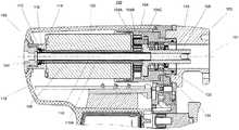
ここで図1及び2を参照すると、外科用装置100の断面図が示される。外科用装置100は、様々な外科的処置中に使用される動力工具である。外科用装置100は、近位端105と遠位端103とを有し、また外科用装置100は、内部構成要素を収容する装置ケーシング118を有する。外科用装置100は、モータ102を備える。モータ102は、モータ102を支持するモータハウジング116及び細長いモータ軸106を含む。モータハウジング116は、定置されており、モータ軸106は、回転することができる。図1及び2に示されるように、モータハウジング116の近位部分は、末端部品150を収納する。末端部品150は、装置ケーシング118を定位置に保持する。例えば、末端部品150は、モータハウジング116の中にねじ止めされ得る。本明細書で論じられる実施形態において、モータ102は、医療用器具を駆動するように動作可能である、いずれの型の電気モータであり得る。モータ102の特性が、外科用装置100の所望の動作特性に基づいて選択され得ることが理解されるべきである。例えば、外科用ドリル、鋸等の1つ又は2つ以上の外科用器具アタッチメントは、連結ヘッド130を介して外科用装置100に取り付けられ得る。いくつかの実施形態において、連結ヘッド130は、外科用器具を収納する付加的駆動アタッチメントを収納し得る。例えば、付加的駆動アタッチメントは、推進力を外科用器具に変換/伝達し得る。加えて、外科用装置100は、Kワイヤを駆動するように動作可能である。具体的には、Kワイヤを収納するKワイヤアタッチメントは、連結ヘッド130を介して外科用装置100に取り付けられ得る。図2に示されるように、操作者は、外科用装置100のハンドル120を握り、トリガー122を使用してモータ102を操作し得る。例えば、トリガー122のうちの1つは、モータ102を第1の方向(即ち、順方向)に回転させることができ、トリガー122のうちの別の1つは、モータ102を第2の方向(即ち、逆方向)に回転させることができる。 With reference now to FIGS. 1 and 2, a cross-sectional view of
モータ102は、細長いモータ軸106を含み、細長いモータ軸106は、ギヤボックス装置104を介して細長い駆動軸108に連通接続される。図1及び2に示されるように、モータ軸106は、モータ102を通ってギヤボックス装置104へと遠位に延在する。ギヤボックス装置104は、駆動軸108にモータ軸106の回転速度及び回転力を変換及び伝達するように構成される。典型的に、外科用動力工具内で使用するための好適なモータは、比較的小さく、かつ軽量であることを要する。より小さく、より軽く、かつより強力なモータは、より高い速度を要求することが理解されるべきである。ゆえに、モータ102は、所望の出力回転力を得るために、取り付け可能な外科用器具の所望の回転速度より高い回転速度で回転し、ギヤボックス装置104は、モータ軸106の回転速度及び回転力を駆動軸108に変換及び伝達するように使用され得る。例えば、いくつかの実施形態において、モータ軸106は、およそ15,000〜20,000RPMで回転することができる一方で、駆動軸108の所望の回転速度は、およそ3,000RPM(即ち、モータ軸106より5〜6倍遅い)である場合がある。別の方法としては、又は加えて、付加的駆動アタッチメントは、回転速度を外科用器具の所望の回転速度に更に減速し得、回転速度はおよそ1,000RPM以下である場合がある。更に、付加的駆動アタッチメントは、例えばバール等の高速切削器具を駆動するために、回転速度を外科用器具の所望の回転速度に加速し得(例えば15,000RPM)、回転速度は、駆動軸108の回転速度をほぼ超える場合もある。モータ102、モータ軸106、駆動軸108、外科用器具等について上述の回転速度は、外科用装置100の所望の動作特性に基づいて選択され得、ゆえに他の値を有し得ることが理解されるべきである。例えば、駆動軸108の所望の回転速度は、外科用装置100の所望の動作特性に応じて、3,000RPM以上又は未満であり得る。したがって、駆動軸108の所望の回転速度は、3,000RPMに限定されず、これは1つの例示的な所望の回転速度に過ぎない。 The
ギヤボックス装置104は、1つ又は2つ以上の工程でモータ102の回転速度及び回転力を変換及び伝達することができる、いずれの型のギヤボックスであり得る。例えば、ギヤボックス装置104は、遊星歯車システムであり得る。例えば、モータ軸106は、太陽歯車104Aに接続され得、駆動軸108は、1つ又は2つ以上の遊星歯車104Bに接続され得る。いくつかの実施形態において、駆動軸108は、駆動軸108を通って、かつ遊星歯車104Bの中へと押されるピン(複数可)104Cを使用して、1つ又は2つ以上の遊星歯車104Bと接続され得る。あるいは、駆動軸108は、駆動軸108と一体であるピン104Cを使用して、1つ又は2つ以上の遊星歯車104Bと接続され得る。ゆえに、ギヤボックス装置104は、モータ軸106のより高い回転速度を駆動軸108のより低い回転速度に変換する。加えて、ギヤボックス装置104は、回転力をモータ軸106から駆動軸108に伝達する。いくつかの実施形態において、モータ軸106のより低い回転力は、より高い回転力に変換され、駆動軸108に伝達される。 The
図1及び2に示されるように、モータ軸106及び駆動軸108は、インラインである。加えて、モータ軸106は、モータ102を通ってギヤボックス装置104へと遠位に延在し、駆動軸108は、ギヤボックス装置104から遠位に延在する。本明細書で論じられる実施形態において、モータ軸106及び駆動軸108は、同軸であり、又は例えば、共通の回転軸101を共有する。モータ軸106及び駆動軸108が同軸であるとき、外科用装置100は、モータ軸106及び駆動軸108が共通の回転軸101を共有しない場合と比較して、より小さくされ得る。加えて、モータ軸106及び駆動軸108は、カニューレを取り付けた軸であり得る。換言すれば、モータ軸106及び駆動軸108は、それぞれの軸の全長を通って延在する中空の中心チャネルを有し得る。上述のように、外科用装置100は、Kワイヤを駆動するように動作可能であり、Kワイヤは、典型的に、外科用装置100自体よりも長い。結果的に、Kワイヤは、外科用装置100を通って(即ち、遠位端103から近位端105へと)全体的に挿入され得、外科用装置100の装置ハウジング118を通って出る。 As shown in FIGS. 1 and 2, the
駆動軸管110は、駆動軸108に連結され得る。駆動軸管110は、ギヤボックス装置104から近位に延在し得る。例えば、駆動軸管110は、ギヤボックス装置104からモータ軸106の中へと近位に延在し得る。モータ軸106がカニューレを取り付けられると、駆動軸管110は、モータ軸106の中空のチャネルを通って延在し得る。具体的には、駆動軸管110は、モータ軸106を通って、かつモータ軸106の近位端を越えて延在し得る。例えば、駆動軸管110の一部分は、モータ軸106の近位端を越えて近位に延在し得る。図1及び2に示されるように、駆動軸管110は、ギヤボックス装置104からモータ軸106の全長を通って近位に延在する。モータ軸106及び駆動軸108と同様に、駆動軸管110は、外科用装置100を通るKワイヤの挿入を収納するためにカニューレを取り付けられ得る。加えて、駆動軸管110は、共通の回転軸101をモータ軸106及び駆動軸108と共有し得る。 The
駆動軸管110は、駆動軸管110が駆動軸108と同じ回転速度で回転することができるように、駆動軸108に連結され得る。いくつかの実施形態において、駆動軸管110及び駆動軸108は、例えば、ギヤボックス装置104に隣接する場所で、合わせて一体的に連結される別個の部品である。他の実施形態において、駆動軸管110及び駆動軸108は、単一の統合された(即ち、単一片の材料から形成される)部品である。上述の両方の場合において、駆動軸管110及び駆動軸108は、同じ回転速度で回転することができる。具体的には、駆動軸管110は、モータ軸106と比較してより低い回転速度で回転することができる。加えて、駆動軸管110及び駆動軸108は、流体が駆動軸管110及び/又は駆動軸108の中空のチャネルからモータ102へと漏出する間隙又は空隙がないように連結される。必要に応じて、駆動軸108の壁部の厚さは、回転力がモータ軸106から駆動軸108に伝達されるため、駆動軸管110の壁部の厚さを超え得るが、一方で駆動軸管110上には本質的に回転力がない。 The
封止部材112は、流体がモータ102の中に漏出することを防止するようにモータ軸106の近位端に隣接して提供され得る。いくつかの実施形態において、封止部材112は、モータハウジング116と駆動軸管110との間に提供され得る。あるいは、他の実施形態において、封止部材112は、末端部品150と駆動軸管110との間に提供され得る。ここで図3Aを参照すると、間隙124は、定置のモータハウジング116の近位部分と、回転することができる駆動軸管110との間に提供される。間隙124は、モータ軸106の近位端を越えて延在する駆動軸管110の一部分を囲繞する、環状リングであり得る。あるいは、間隙124は、モータ軸106の近位端を越えて延在する駆動軸管110の一部分を囲繞する任意の形状を有する空隙であり得る。具体的には、間隙124は、モータハウジング116の近位部分の内側表面116Aと、駆動軸管110の外側表面110Aとの間に提供される。間隙124は、駆動軸管110が回転し得る隙間(又は空隙)を提供する。流体が間隙124を通って漏出することを阻止するため、封止部材112は、間隙124内に提供され得る。封止部材112の少なくとも一部分は、駆動軸管110の外側表面110Aに接触し得る。駆動軸管110の外側表面110Aに接触する封止部材112の一部分は、駆動軸管110の外側表面110A全体の周囲に円周方向に延在し得る。例えば、封止部材112は、リップ封止、Oリング、又は他の任意の型の封止であり得る。封止部材112は、例えばゴム(即ち、NBR、シリコーン等)のように、流体がモータ102の中に漏出することを阻止するために好適ないずれの型の材料からも作製され得る。 A sealing
封止部材112は、駆動軸管110の外側表面110Aの周囲に提供され得る。例えば、図3A及び3Bを参照すると、封止部材112は、コンセントリックリング112A及びリップ112Bを有し得る。リップ112Bは、コンセントリックリング112Aから半径方向に延在し得、リップ112Bは、コンセントリックリング112Aから先細であり得る。リップ112Bを先細にすることによって、駆動軸管110の外側表面110Aに接触するリップ112Bの一部分は、低減され得る。コンセントリックリング112Aは、リップ112Bの少なくとも一部分が駆動軸管110の外側表面110Aに接触するように、駆動軸管110の外側表面110Aの周囲に提供され得る。ゆえに、封止部材112は、流体がモータ102の中に漏出することを阻止する。 A sealing
封止部材112に加えて、支持部材114が、モータ軸106の近位端に隣接して提供され得る。いくつかの実施形態において、支持部材114は、モータハウジング116と駆動軸管110との間に提供され得る。あるいは、別の実施形態において、支持部材114は、末端部品150と駆動軸管110との間に提供され得る。例えば、支持部材114は、モータハウジング116の近位部分と駆動軸管110との間に提供される間隙124内に提供され得、そして封止部材112とモータ軸106の近位端との間に配設され得る。駆動軸管110は、支持部材114を介して装着され得る。支持部材114は、駆動軸管110がモータ軸106に接触しないように、駆動軸管110のための支持を提供する。上述のように、モータ軸106は、駆動軸管110よりも高い回転速度で回転し得る。したがって、駆動軸管110及びモータ軸106は、接触しないはずである。図3Aに示されるように、空隙126は、駆動軸管110とモータ軸106との間に提供される。具体的には、空隙126は、駆動軸管110の外側表面110Aとモータ軸106の内側表面との間に提供される。空隙126は、例えば、駆動軸管110の外側表面110Aの周囲に延在する環状リングであり得る。支持部材114は、駆動軸管110とモータ軸106との間に空隙126を維持するように構成され得る。加えて、支持部材114は、駆動軸管110が支持部材114内で回転することを可能にする。例えば、支持部材114は、玉軸受であり得る。 In addition to the sealing
上述の(外科用装置100の近位端付近に提供される)封止部材112及び支持部材114と同様に、遠位の封止部材132及び遠位の支持部材134は、外科用装置100の遠位端付近に提供され得る。例えば、図1及び2に示されるように、遠位の封止部材132及び遠位の支持部材134は、駆動軸108の遠位端に隣接して提供され得る。遠位の封止部材132及び遠位の支持部材134は、外科用装置100の定置の構成要素と、回転し得る駆動軸108との間の空隙内に提供され得る。遠位の支持部材134は、例えば、玉軸受であり得、駆動軸108のための支持を提供し得るが、一方で駆動軸108が遠位の支持部材134内で回転することを可能にする。加えて、遠位の封止部材132は、例えば、リップ封止であり得、流体が駆動軸108とモータ102との間に漏出することを阻止し得る。 Similar to the sealing
本明細書で論じられる実施形態によれば、外科用装置内により信頼性のある封止を提供することは可能である。例えば、封止部材が(より速く回転する)モータ軸とモータとの間ではなく、(より遅く回転する)駆動軸管とモータとの間で封止するため、より信頼性のある封止が提供される。加えて、付加的封止部材がモータ軸と駆動軸との間で封止するように要求されないため、外科用装置のモータを保護するために必要とされる封止部材の数を低減することは可能である。より速く回転する(より低い回転力の)モータ軸でよりも、より遅く回転する(より高い回転力の)駆動軸管での方が存在する摩擦が少ないため、モータでの抗力モーメントを低減することも可能である。更に、Kワイヤと駆動軸管との間の速度差を低減することによって、Kワイヤ及び回転軸の両方でのノイズ及び摩耗を低減することが可能である。 According to the embodiments discussed herein, it is possible to provide a more reliable seal within the surgical device. For example, the sealing member seals between the drive shaft tube (rotating slower) and the motor rather than between the motor shaft (rotating faster) and the motor, thus providing a more reliable seal Provided. In addition, since no additional sealing member is required to seal between the motor shaft and the drive shaft, the number of sealing members required to protect the surgical device motor is reduced. Is possible. Reduces the drag moment at the motor because there is less friction on the drive shaft tube that rotates slower (higher torque) than on the motor shaft that rotates faster (lower torque) It is also possible. Furthermore, by reducing the speed difference between the K wire and the drive shaft tube, it is possible to reduce noise and wear on both the K wire and the rotating shaft.
主題は、構造的特徴及び/又は方法論的行為に特有な言語で記載されたが、添付される「特許請求の範囲」において定義される主題が上記の特定の特徴又は行為に必ずしも限定されるものではないことが理解されるべきである。むしろ、上記の特定の特徴及び行為は、「特許請求の範囲」を実施する例示的形態として開示される。 Although the subject matter has been described in a language specific to structural features and / or methodological acts, the subject matter defined in the appended claims is not necessarily limited to the specific features or acts described above It should be understood that this is not the case. Rather, the specific features and acts described above are disclosed as example forms of implementing the "claims".
〔実施の態様〕
(1) 外科用装置であって、
カニューレを取り付けたモータ軸(cannulated motor shaft)を備えるモータであって、前記カニューレを取り付けたモータ軸が近位端及び遠位端を有する、モータと、
ギヤボックス装置と、
前記ギヤボックス装置を介して前記カニューレを取り付けたモータ軸に連通接続される駆動軸であって、前記ギヤボックス装置から遠位に延在し、前記カニューレを取り付けたモータ軸が前記ギヤボックス装置へと遠位に延在し、前記カニューレを取り付けたモータ軸及び前記駆動軸が、共通の回転軸を有する、駆動軸と、
前記ギヤボックス装置から前記カニューレを取り付けたモータ軸を通り、前記カニューレを取り付けたモータ軸の前記近位端を越えて近位に延在する、前記駆動軸に連結される駆動軸管と、
前記カニューレを取り付けたモータ軸の前記近位端に隣接して配置される封止部材であって、前記駆動軸管と前記モータとの間に封止を提供する、封止部材と、を備える、外科用装置。
(2) 前記カニューレを取り付けたモータ軸の前記近位端に隣接して配置される支持部材を更に備え、前記駆動軸管が、空隙が前記駆動軸管と前記カニューレを取り付けたモータ軸との間に提供されるように、前記支持部材上に装着される、実施態様1に記載の外科用装置。
(3) 前記支持部材が玉軸受である、実施態様2に記載の外科用装置。
(4) 前記ギヤボックス装置が、前記カニューレを取り付けたモータ軸のより高い回転速度を前記駆動軸のより低い回転速度に変換するように構成される、実施態様1に記載の外科用装置。
(5) 前記駆動軸管が、前記駆動軸管が前記駆動軸の前記より低い回転速度で回転するように構成されるように、前記駆動軸に連結される、実施態様4に記載の外科用装置。Embodiment
(1) a surgical device,
A motor comprising a cannulated motor shaft, wherein the cannulated motor shaft has a proximal end and a distal end;
A gear box device;
A drive shaft communicatively connected to the motor shaft with the cannula attached via the gear box device, extending distally from the gear box device, and the motor shaft with the cannula attached to the gear box device; A drive shaft extending distally, wherein the cannulated motor shaft and the drive shaft have a common rotational axis;
A drive shaft tube connected to the drive shaft extending from the gearbox device through the motor shaft with the cannula attached and beyond the proximal end of the motor shaft with the cannula attached;
A sealing member disposed adjacent to the proximal end of the cannulated motor shaft, the sealing member providing a seal between the drive shaft tube and the motor. Surgical equipment.
(2) a support member disposed adjacent to the proximal end of the motor shaft to which the cannula is attached, wherein the drive shaft tube has a gap between the drive shaft tube and the motor shaft to which the cannula is attached; The surgical apparatus according to
(3) The surgical apparatus according to embodiment 2, wherein the support member is a ball bearing.
4. The surgical apparatus of
(5) The surgical of embodiment 4, wherein the drive shaft tube is coupled to the drive shaft such that the drive shaft tube is configured to rotate at the lower rotational speed of the drive shaft. apparatus.
(6) 前記駆動軸管及び前記駆動軸が、前記駆動軸管が前記駆動軸の前記より低い回転速度で回転するように構成されるように、単一片の材料から形成される、実施態様4に記載の外科用装置。
(7) 前記封止部材の少なくとも一部分が、前記駆動軸管の外側表面に接触する、実施態様1に記載の外科用装置。
(8) 前記封止部材がコンセントリックリング及びリップを備え、前記リップが前記コンセントリックリングから半径方向に延在し、前記コンセントリックリングが前記駆動軸管の外側表面の周囲に配設され、前記リップの少なくとも一部分が前記駆動軸管の前記外側表面に接触する、実施態様7に記載の外科用装置。
(9) 前記モータを支持するモータハウジングを更に備え、間隙が、前記モータハウジングの近位部分の内側表面と前記駆動軸管の前記外側表面との間に画定され、前記封止部材及び前記支持部材のうちの少なくとも1つが、前記間隙内に配設される、実施態様7に記載の外科用装置。
(10) 外科用装置とともに使用するための封止システムであって、前記外科用装置が、ギヤボックス装置を介して駆動軸に連通接続されるカニューレを取り付けたモータ軸を有するモータを含み、前記駆動軸が、前記ギヤボックス装置から遠位に延在し、前記カニューレを取り付けたモータ軸が、前記ギヤボックス装置へと遠位に延在し、前記封止システムが、
前記カニューレを取り付けたモータ軸を通って延在する、前記駆動軸に連結される細長い駆動軸管と、
前記細長い駆動軸管の少なくとも一部分と接触して配設される封止部材であって、前記細長い駆動軸管が、前記駆動軸の回転速度で回転するように構成される、封止部材と、を備える、封止システム。(6) Embodiment 4 wherein the drive shaft tube and the drive shaft are formed from a single piece of material such that the drive shaft tube is configured to rotate at the lower rotational speed of the drive shaft. A surgical device according to
(7) The surgical apparatus according to
(8) The sealing member includes a concentric ring and a lip, the lip extends in a radial direction from the concentric ring, and the concentric ring is disposed around an outer surface of the drive shaft tube, The surgical apparatus according to embodiment 7, wherein at least a portion of the lip contacts the outer surface of the drive shaft tube.
(9) A motor housing supporting the motor is further provided, and a gap is defined between the inner surface of the proximal portion of the motor housing and the outer surface of the drive shaft tube, and the sealing member and the support The surgical apparatus according to embodiment 7, wherein at least one of the members is disposed within the gap.
(10) A sealing system for use with a surgical device, wherein the surgical device includes a motor having a motor shaft with a cannula connected in communication with a drive shaft via a gearbox device; A drive shaft extends distally from the gearbox device, the cannulated motor shaft extends distally to the gearbox device, and the sealing system comprises:
An elongate drive shaft tube coupled to the drive shaft extending through the motor shaft with the cannula attached thereto;
A sealing member disposed in contact with at least a portion of the elongate drive shaft tube, wherein the elongate drive shaft tube is configured to rotate at a rotational speed of the drive shaft; A sealing system comprising:
(11) 前記カニューレを取り付けたモータ軸が近位端及び遠位端を有し、前記細長い駆動軸管の少なくとも一部分が、前記カニューレを取り付けたモータ軸の前記近位端を越えて延在し、前記封止部材が、前記カニューレを取り付けたモータ軸の前記近位端を越えて延在する前記細長い駆動軸管の前記一部分と接触して配設される、実施態様10に記載の封止システム。
(12) 前記駆動軸の前記回転速度が、およそ3,000RPM以下である、実施態様10に記載の封止システム。
(13) 前記細長い駆動軸管が、前記駆動軸に一体的に連結される、実施態様10に記載の封止システム。
(14) 前記細長い駆動軸管及び前記駆動軸が、単一片の材料から形成される、実施態様13に記載の封止システム。
(15) 前記封止部材がコンセントリックリング及びリップを備え、前記リップが前記コンセントリックリングから半径方向に延在し、前記コンセントリックリングが前記細長い駆動軸管の外側表面の周囲に配設され、前記リップの少なくとも一部分が前記細長い駆動軸管の前記外側表面に接触する、実施態様10に記載の封止システム。(11) The cannulated motor shaft has a proximal end and a distal end, and at least a portion of the elongate drive shaft tube extends beyond the proximal end of the cannulated motor shaft. 11. The seal of embodiment 10, wherein the sealing member is disposed in contact with the portion of the elongate drive shaft tube that extends beyond the proximal end of the cannulated motor shaft. system.
(12) The sealing system according to embodiment 10, wherein the rotational speed of the drive shaft is approximately 3,000 RPM or less.
(13) The sealing system according to embodiment 10, wherein the elongate drive shaft tube is integrally connected to the drive shaft.
14. The sealing system according to embodiment 13, wherein the elongate drive shaft tube and the drive shaft are formed from a single piece of material.
(15) The sealing member includes a concentric ring and a lip, the lip extends in a radial direction from the concentric ring, and the concentric ring is disposed around an outer surface of the elongated drive shaft tube. Embodiment 11. The sealing system of embodiment 10, wherein at least a portion of the lip contacts the outer surface of the elongate drive shaft tube.
(16) 外科用装置の製造方法であって、
カニューレを取り付けたモータ軸を備えるモータを提供することであって、前記カニューレを取り付けたモータ軸が近位端及び遠位端を画定する、提供することと、
ギヤボックス装置を提供することと、
前記ギヤボックス装置を介して前記カニューレを取り付けたモータ軸に連通接続される駆動軸を提供することであって、前記駆動軸が前記ギヤボックス装置から遠位に延在し、前記カニューレを取り付けたモータ軸が前記ギヤボックス装置へと遠位に延在し、前記カニューレを取り付けたモータ軸及び前記駆動軸が、共通の回転軸を有する、提供することと、
前記ギヤボックス装置から前記カニューレを取り付けたモータ軸を通り、前記カニューレを取り付けたモータ軸の前記近位端を越えて近位に延在する、前記駆動軸に連結される駆動軸管を提供することと、
前記カニューレを取り付けたモータ軸の前記近位端に隣接する封止部材を提供することであって、前記封止部材が、前記駆動軸管と前記モータとの間に封止を提供する、提供することと、を含む、方法。
(17) 前記カニューレを取り付けたモータ軸の前記近位端に隣接する支持部材を提供することを更に含み、前記駆動軸管が、空隙が前記駆動軸管と前記カニューレを取り付けたモータ軸との間に提供されるように、前記支持部材上に装着される、実施態様16に記載の方法。
(18) 前記ギヤボックス装置が、前記カニューレを取り付けたモータ軸のより高い回転速度を前記駆動軸のより低い回転速度に変換するように構成される、実施態様16に記載の方法。
(19) 前記封止部材がコンセントリックリング及びリップを備え、前記リップが前記コンセントリックリングから半径方向に延在し、前記コンセントリックリングが前記駆動軸管の外側表面の周囲に配設され、前記リップの少なくとも一部分が前記駆動軸管の前記外側表面に接触する、実施態様16に記載の方法。
(20) 前記モータを支持するモータハウジングを提供することを更に含み、間隙が、前記モータハウジングの近位部分の内側表面と前記駆動軸管の前記外側表面との間に画定され、前記封止部材及び前記支持部材のうちの少なくとも1つが、前記間隙内に配設される、実施態様16に記載の方法。(16) A method of manufacturing a surgical device,
Providing a motor comprising a cannulated motor shaft, wherein the cannulated motor shaft defines a proximal end and a distal end;
Providing a gearbox device;
Providing a drive shaft communicatively connected to the motor shaft with the cannula attached through the gearbox device, the drive shaft extending distally from the gearbox device and attaching the cannula Providing a motor shaft extending distally to the gearbox device, wherein the cannulated motor shaft and the drive shaft have a common axis of rotation;
A drive shaft tube coupled to the drive shaft extends from the gearbox device through the motor shaft to which the cannula is attached and extends proximally beyond the proximal end of the motor shaft to which the cannula is attached. And
Providing a sealing member adjacent to the proximal end of the cannulated motor shaft, the sealing member providing a seal between the drive shaft tube and the motor And a method comprising:
(17) further comprising providing a support member adjacent to the proximal end of the motor shaft with the cannula attached thereto, wherein the drive shaft tube has a gap between the drive shaft tube and the motor shaft with the cannula attached thereto; Embodiment 17. The method of embodiment 16 wherein the method is mounted on the support member as provided therebetween.
18. The method of embodiment 16, wherein the gearbox device is configured to convert a higher rotational speed of the cannulated motor shaft to a lower rotational speed of the drive shaft.
(19) The sealing member includes a concentric ring and a lip, the lip extends in a radial direction from the concentric ring, and the concentric ring is disposed around an outer surface of the drive shaft tube, Embodiment 17. The method of embodiment 16, wherein at least a portion of the lip contacts the outer surface of the drive shaft tube.
(20) further comprising providing a motor housing that supports the motor, wherein a gap is defined between an inner surface of a proximal portion of the motor housing and the outer surface of the drive shaft tube; Embodiment 17. The method of embodiment 16, wherein at least one of a member and the support member is disposed in the gap.
Claims (7)
Translated fromJapaneseカニューレを取り付けたモータ軸を備えるモータであって、前記カニューレを取り付けたモータ軸が近位端及び遠位端を有する、モータと、
ギヤボックス装置と、
前記ギヤボックス装置を介して前記カニューレを取り付けたモータ軸に連通接続される駆動軸であって、前記ギヤボックス装置から遠位に延在し、前記カニューレを取り付けたモータ軸が前記ギヤボックス装置へと遠位に延在し、前記カニューレを取り付けたモータ軸及び前記駆動軸が、共通の回転軸を有する、駆動軸と、
前記ギヤボックス装置から前記カニューレを取り付けたモータ軸を通り、前記カニューレを取り付けたモータ軸の前記近位端を越えて近位に延在する、前記駆動軸に連結される駆動軸管であって、前記駆動軸管が、前記駆動軸と同じ速度で回転するように前記駆動軸に連結される駆動軸管と、
前記カニューレを取り付けたモータ軸の前記近位端に隣接して配置される封止部材であって、前記駆動軸管と前記モータとの間に封止を提供する、封止部材と、を備え、
前記カニューレを取り付けたモータ軸の前記近位端に隣接して配置される玉軸受部材を更に備え、前記駆動軸管が、空隙が前記駆動軸管と前記カニューレを取り付けたモータ軸との間に提供されるように、前記玉軸受部材上に装着され、
前記封止部材がコンセントリックリング及びリップを備え、前記リップが前記コンセントリックリングから半径方向に延在し、前記コンセントリックリングが前記駆動軸管の外側表面の周囲に配設され、
前記リップは前記コンセントリックリングから前記駆動軸管に向けて先細であり、前記リップの前記先細部分が前記駆動軸管の前記外側表面に接触する、外科用装置。A surgical device,
A motor comprising a cannulated motor shaft, wherein the cannulated motor shaft has a proximal end and a distal end;
A gear box device;
A drive shaft communicatively connected to the motor shaft with the cannula attached via the gear box device, extending distally from the gear box device, and the motor shaft with the cannula attached to the gear box device; A drive shaft extending distally, wherein the cannulated motor shaft and the drive shaft have a common rotational axis;
A drive shaft tube coupled to the drive shaft extending from the gearbox device through the motor shaft with the cannula attached and extending proximally beyond the proximal end of the motor shaft with the cannula attached; A drive shaft tube coupled to the drive shaft so that the drive shaft tube rotates at the same speed as the drive shaft;
A sealing member disposed adjacent to the proximal end of the motor shaft with the cannula attached thereto, the sealing member providing a seal between the drive shaft tube and the motor; ,
A ball bearing member disposed adjacent to the proximal end of the cannulated motor shaft, the drive shaft tube having a gap between the drive shaft tube and the cannulated motor shaft; As provided, mounted on the ball bearing member;
The sealing member includes a concentric ring and a lip, the lip extends radially from the concentric ring, and the concentric ring is disposed around an outer surface of the drive shaft tube;
The lip is tapered toward the drive shaft tube from the concentric rings, the tapered portion of the lip you contact with said outer surface of said drive shaft tube, a surgical device.
前記カニューレを取り付けたモータ軸を通って延在する、前記駆動軸に連結される細長い駆動軸管であって、前記細長い駆動軸管が、前記駆動軸と同じ速度で回転するように前記駆動軸に連結される細長い駆動軸管と、
前記細長い駆動軸管の少なくとも一部分と接触して配設され、前記細長い駆動軸管と前記モータとの間に封止を提供する封止部材であって、前記細長い駆動軸管が、前記駆動軸の回転速度で回転するように構成される、封止部材と、を備え、前記カニューレを取り付けたモータ軸の前記近位端に隣接して配置される玉軸受部材を更に備え、前記細長い駆動軸管が、空隙が前記細長い駆動軸管と前記カニューレを取り付けたモータ軸との間に提供されるように、前記玉軸受部材上に装着され、
前記封止部材がコンセントリックリング及びリップを備え、前記リップが前記コンセントリックリングから半径方向に延在し、前記コンセントリックリングが前記細長い駆動軸管の外側表面の周囲に配設され、
前記リップは前記コンセントリックリングから前記細長い駆動軸管に向けて先細であり、前記リップの前記先細部分が前記細長い駆動軸管の前記外側表面に接触する、封止システム。A sealing system for use with a surgical device, wherein the surgical device includes a motor having a motor shaft with a cannula communicatively connected to the drive shaft via a gearbox device, the drive shaft comprising: A motor shaft extending distally from the gearbox device and attached to the cannula extends distally to the gearbox device, the sealing system comprising:
An elongate drive shaft tube coupled to the drive shaft extending through the cannulated motor shaft, wherein the elongate drive shaft tube rotates at the same speed as the drive shaft. An elongated drive shaft tube coupled to the
A sealing member disposed in contact with at least a portion of the elongate drive shaft tube and providing a seal between the elongate drive shaft tube and the motor, wherein the elongate drive shaft tube is the drive shaft. An elongate drive shaft further comprising a ball bearing member disposed adjacent to the proximal end of the cannulated motor shaft, the sealing member configured to rotate at a rotational speed of A tube is mounted on the ball bearing member such that a gap is provided between the elongated drive shaft tube and the cannulated motor shaft;
The sealing member comprises a concentric ring and a lip, the lip extending radially from the concentric ring, the concentric ring being disposed around an outer surface of the elongate drive shaft tube;
The lip is tapered toward the elongate drive shaft tube from the concentric rings, the tapered portion of the lip contact with the outer surface of the elongate drive shaft tube, a sealing system.
Applications Claiming Priority (2)
| Application Number | Priority Date | Filing Date | Title |
|---|---|---|---|
| US13/533,446US10617431B2 (en) | 2012-06-26 | 2012-06-26 | Systems and apparatus for providing motor protection in a power tool and method of manufacturing the same |
| US13/533,446 | 2012-06-26 |
Publications (2)
| Publication Number | Publication Date |
|---|---|
| JP2014004374A JP2014004374A (en) | 2014-01-16 |
| JP6469339B2true JP6469339B2 (en) | 2019-02-13 |
Family
ID=48700356
Family Applications (1)
| Application Number | Title | Priority Date | Filing Date |
|---|---|---|---|
| JP2013132341AActiveJP6469339B2 (en) | 2012-06-26 | 2013-06-25 | System and apparatus for providing motor protection in power tools and method of manufacturing the same |
Country Status (7)
| Country | Link |
|---|---|
| US (1) | US10617431B2 (en) |
| EP (1) | EP2679177B1 (en) |
| JP (1) | JP6469339B2 (en) |
| KR (1) | KR102200635B1 (en) |
| CN (2) | CN103507047A (en) |
| BR (1) | BR102013016451B1 (en) |
| CA (1) | CA2820668A1 (en) |
Families Citing this family (6)
| Publication number | Priority date | Publication date | Assignee | Title |
|---|---|---|---|---|
| AU2012352199B2 (en) | 2011-12-16 | 2017-08-17 | Stryker Corporation | Specimen trap with a removable catch tray for retrieving tissue samples from a fluid stream during a medical procedure |
| EP3653139B1 (en) | 2014-10-30 | 2024-07-03 | Stryker Corporation | Surgical tool with an aseptic power module that enters a specific operating state based on the type of handpiece to which the module is attached |
| JP6785836B2 (en)* | 2016-02-25 | 2020-11-18 | 株式会社ダイヘン | Drive device |
| US10869684B2 (en)* | 2018-02-13 | 2020-12-22 | Covidien Lp | Powered tissue resecting device |
| US11331107B2 (en)* | 2019-01-31 | 2022-05-17 | Gyrus Acmi, Inc. | Medical device with removable motor |
| WO2022103894A1 (en)* | 2020-11-12 | 2022-05-19 | Nuvasive, Inc. | Power modules for bone anchor and stylet insertion |
Family Cites Families (18)
| Publication number | Priority date | Publication date | Assignee | Title |
|---|---|---|---|---|
| US3120845A (en)* | 1961-02-20 | 1964-02-11 | David B Horner | Self-powered surgical drill |
| US4736742A (en) | 1986-04-03 | 1988-04-12 | Minnesota Mining And Manufacturing Company | Device for driving tools used in orthopedic surgery |
| US5133729A (en) | 1990-08-17 | 1992-07-28 | Smith & Nephew Dyonics Inc. | Motor driven hand piece for a surgical tool |
| US5207697A (en)* | 1991-06-27 | 1993-05-04 | Stryker Corporation | Battery powered surgical handpiece |
| DE10004265A1 (en)* | 2000-02-01 | 2001-08-09 | Lenze Gmbh & Co Kg Aerzen | Sealing system between a shaft and a fixed housing part |
| WO2001067970A1 (en) | 2000-03-15 | 2001-09-20 | Bioaccess, Inc. | Orthopedic medical device |
| CN1221466C (en) | 2000-05-29 | 2005-10-05 | 安格斯公司 | Quick connect fill system |
| US6880223B2 (en)* | 2002-04-25 | 2005-04-19 | Milwaukee Electric Tool Corporation | Grease slinger |
| US6958071B2 (en) | 2002-07-13 | 2005-10-25 | Stryker Corporation | Surgical tool system |
| US7237990B2 (en) | 2002-08-08 | 2007-07-03 | Stryker Corporation | Surgical tool system with quick release coupling assembly |
| US7604643B2 (en)* | 2004-04-06 | 2009-10-20 | Synthes Usa, Llc | Adjustable tool for cannulated fasteners |
| US7597699B2 (en) | 2005-07-25 | 2009-10-06 | Rogers William G | Motorized surgical handpiece |
| US8945164B2 (en) | 2005-10-27 | 2015-02-03 | Medtronic Xomed, Inc. | Guard device for surgical cutting and evoked potential monitoring system |
| US9017333B2 (en)* | 2008-04-17 | 2015-04-28 | Warsaw Orthopedic, Inc. | Surgical tool |
| JP5323422B2 (en) | 2008-08-21 | 2013-10-23 | 株式会社長田中央研究所 | Therapeutic motor |
| EP2238920B1 (en)* | 2009-04-09 | 2013-02-20 | Arthrex Inc | Medical, in particular surgical, handpiece |
| JP5533372B2 (en) | 2010-07-09 | 2014-06-25 | 株式会社ジェイテクト | Sealing structure |
| US9080423B2 (en) | 2010-10-11 | 2015-07-14 | National Oilwell Varco, L.P. | 3-ring non-extrusion seal assembly and method |
- 2012
- 2012-06-26USUS13/533,446patent/US10617431B2/enactiveActive
- 2013
- 2013-06-25CACA2820668Apatent/CA2820668A1/ennot_activeAbandoned
- 2013-06-25JPJP2013132341Apatent/JP6469339B2/enactiveActive
- 2013-06-26CNCN201310258181.3Apatent/CN103507047A/enactivePending
- 2013-06-26BRBR102013016451-8Apatent/BR102013016451B1/enactiveIP Right Grant
- 2013-06-26CNCN202011106642.1Apatent/CN112247916A/enactivePending
- 2013-06-26KRKR1020130073429Apatent/KR102200635B1/enactiveActive
- 2013-06-26EPEP13173767.8Apatent/EP2679177B1/enactiveActive
Also Published As
| Publication number | Publication date |
|---|---|
| CA2820668A1 (en) | 2013-12-26 |
| US20130340553A1 (en) | 2013-12-26 |
| KR102200635B1 (en) | 2021-01-13 |
| BR102013016451A2 (en) | 2015-07-14 |
| EP2679177B1 (en) | 2016-01-06 |
| CN112247916A (en) | 2021-01-22 |
| CN103507047A (en) | 2014-01-15 |
| US10617431B2 (en) | 2020-04-14 |
| BR102013016451B1 (en) | 2021-06-01 |
| KR20140001143A (en) | 2014-01-06 |
| EP2679177A1 (en) | 2014-01-01 |
| JP2014004374A (en) | 2014-01-16 |
Similar Documents
| Publication | Publication Date | Title |
|---|---|---|
| JP6469339B2 (en) | System and apparatus for providing motor protection in power tools and method of manufacturing the same | |
| KR102157173B1 (en) | System comprising medical instrument and instrument interface | |
| US10226260B2 (en) | Dynamic locking device | |
| US8456051B2 (en) | High reliability generator with dual drive path | |
| EP2514981B1 (en) | Flexible wire | |
| JP2006234165A (en) | Rotary device driving system | |
| US10088033B2 (en) | Drive mechanism for a spin test rig | |
| JP6007418B2 (en) | Secure drive chuck and bar arrangement for dental handpieces | |
| JP2008164170A (en) | Gear with integral overcouple protection | |
| CN109998890A (en) | Hand-held device with hollow piston | |
| KR20110034660A (en) | Planetary gearbox | |
| US11309764B2 (en) | Systems and apparatus for providing motor protection in a power tool and method of manufacturing the same | |
| US8484857B2 (en) | Component for axially aligning two shafts through intermediary materials | |
| US11116387B2 (en) | Insertion device and endoscope | |
| EP3244330A3 (en) | Adapter assembly with pulley system and worm gear drive for interconnecting electromechanical surgical devices and surgical end effectors | |
| FI121871B (en) | Power transmission device and method | |
| US20140030673A1 (en) | Dental handpiece | |
| CN114813565A (en) | Multistage-driven nondestructive testing auxiliary system | |
| JP2016047761A (en) | Drive device |
Legal Events
| Date | Code | Title | Description |
|---|---|---|---|
| A621 | Written request for application examination | Free format text:JAPANESE INTERMEDIATE CODE: A621 Effective date:20160624 | |
| A131 | Notification of reasons for refusal | Free format text:JAPANESE INTERMEDIATE CODE: A131 Effective date:20170725 | |
| A521 | Request for written amendment filed | Free format text:JAPANESE INTERMEDIATE CODE: A523 Effective date:20171011 | |
| A131 | Notification of reasons for refusal | Free format text:JAPANESE INTERMEDIATE CODE: A131 Effective date:20180130 | |
| A601 | Written request for extension of time | Free format text:JAPANESE INTERMEDIATE CODE: A601 Effective date:20180427 | |
| A521 | Request for written amendment filed | Free format text:JAPANESE INTERMEDIATE CODE: A523 Effective date:20180517 | |
| A02 | Decision of refusal | Free format text:JAPANESE INTERMEDIATE CODE: A02 Effective date:20180731 | |
| A521 | Request for written amendment filed | Free format text:JAPANESE INTERMEDIATE CODE: A523 Effective date:20181115 | |
| A911 | Transfer to examiner for re-examination before appeal (zenchi) | Free format text:JAPANESE INTERMEDIATE CODE: A911 Effective date:20181126 | |
| TRDD | Decision of grant or rejection written | ||
| A01 | Written decision to grant a patent or to grant a registration (utility model) | Free format text:JAPANESE INTERMEDIATE CODE: A01 Effective date:20181218 | |
| A61 | First payment of annual fees (during grant procedure) | Free format text:JAPANESE INTERMEDIATE CODE: A61 Effective date:20190116 | |
| R150 | Certificate of patent or registration of utility model | Ref document number:6469339 Country of ref document:JP Free format text:JAPANESE INTERMEDIATE CODE: R150 | |
| R250 | Receipt of annual fees | Free format text:JAPANESE INTERMEDIATE CODE: R250 | |
| R250 | Receipt of annual fees | Free format text:JAPANESE INTERMEDIATE CODE: R250 | |
| R250 | Receipt of annual fees | Free format text:JAPANESE INTERMEDIATE CODE: R250 | |
| R250 | Receipt of annual fees | Free format text:JAPANESE INTERMEDIATE CODE: R250 |