JP6467872B2 - Hydroponics system - Google Patents
Hydroponics systemInfo
- Publication number
- JP6467872B2 JP6467872B2JP2014224934AJP2014224934AJP6467872B2JP 6467872 B2JP6467872 B2JP 6467872B2JP 2014224934 AJP2014224934 AJP 2014224934AJP 2014224934 AJP2014224934 AJP 2014224934AJP 6467872 B2JP6467872 B2JP 6467872B2
- Authority
- JP
- Japan
- Prior art keywords
- cultivation
- panel
- hydroponic
- hydroponic cultivation
- unit
- Prior art date
- Legal status (The legal status is an assumption and is not a legal conclusion. Google has not performed a legal analysis and makes no representation as to the accuracy of the status listed.)
- Active
Links
- 239000003501hydroponicsSubstances0.000titleclaimsdescription23
- 238000000926separation methodMethods0.000claimsdescription5
- 238000000034methodMethods0.000claimsdescription4
- 230000001902propagating effectEffects0.000claimsdescription3
- 238000005452bendingMethods0.000claimsdescription2
- 230000001678irradiating effectEffects0.000claimsdescription2
- 239000007788liquidSubstances0.000description47
- 239000003337fertilizerSubstances0.000description45
- 241000196324EmbryophytaSpecies0.000description10
- 229910052751metalInorganic materials0.000description7
- 239000002184metalSubstances0.000description7
- 235000013311vegetablesNutrition0.000description5
- CURLTUGMZLYLDI-UHFFFAOYSA-NCarbon dioxideChemical compoundO=C=OCURLTUGMZLYLDI-UHFFFAOYSA-N0.000description4
- 240000008415Lactuca sativaSpecies0.000description2
- 229910052782aluminiumInorganic materials0.000description2
- XAGFODPZIPBFFR-UHFFFAOYSA-NaluminiumChemical compound[Al]XAGFODPZIPBFFR-UHFFFAOYSA-N0.000description2
- 229910002092carbon dioxideInorganic materials0.000description2
- 239000001569carbon dioxideSubstances0.000description2
- 210000003608feceAnatomy0.000description2
- 239000000835fiberSubstances0.000description2
- 238000003306harvestingMethods0.000description2
- 239000010871livestock manureSubstances0.000description2
- 238000012423maintenanceMethods0.000description2
- 238000004519manufacturing processMethods0.000description2
- 239000003595mistSubstances0.000description2
- -1polypropylenePolymers0.000description2
- 230000000644propagated effectEffects0.000description2
- 239000002699waste materialSubstances0.000description2
- 229910001316Ag alloyInorganic materials0.000description1
- 229910000838Al alloyInorganic materials0.000description1
- 235000007294Brassica nipposinicaNutrition0.000description1
- 241000342995Brassica rapa subsp. nipposinicaSpecies0.000description1
- 235000003228Lactuca sativaNutrition0.000description1
- 239000004698PolyethyleneSubstances0.000description1
- 239000004743PolypropyleneSubstances0.000description1
- 239000004793PolystyreneSubstances0.000description1
- BQCADISMDOOEFD-UHFFFAOYSA-NSilverChemical compound[Ag]BQCADISMDOOEFD-UHFFFAOYSA-N0.000description1
- 244000300264Spinacia oleraceaSpecies0.000description1
- 235000009337Spinacia oleraceaNutrition0.000description1
- 229910000831SteelInorganic materials0.000description1
- 241000607479Yersinia pestisSpecies0.000description1
- 239000003905agrochemicalSubstances0.000description1
- 238000004378air conditioningMethods0.000description1
- 244000052616bacterial pathogenSpecies0.000description1
- 239000011094fiberboardSubstances0.000description1
- 239000002657fibrous materialSubstances0.000description1
- 239000006260foamSubstances0.000description1
- 235000013305foodNutrition0.000description1
- 235000008216herbsNutrition0.000description1
- 239000012784inorganic fiberSubstances0.000description1
- 238000009434installationMethods0.000description1
- 230000009545invasionEffects0.000description1
- 230000033001locomotionEffects0.000description1
- 238000012986modificationMethods0.000description1
- 230000004048modificationEffects0.000description1
- 230000035699permeabilityEffects0.000description1
- 239000000575pesticideSubstances0.000description1
- 229920000573polyethylenePolymers0.000description1
- 229920001155polypropylenePolymers0.000description1
- 229920002223polystyrenePolymers0.000description1
- 229920002635polyurethanePolymers0.000description1
- 239000004814polyurethaneSubstances0.000description1
- 230000001737promoting effectEffects0.000description1
- 238000002310reflectometryMethods0.000description1
- 229920005989resinPolymers0.000description1
- 239000011347resinSubstances0.000description1
- 235000012045saladNutrition0.000description1
- 229910052709silverInorganic materials0.000description1
- 239000004332silverSubstances0.000description1
- 239000007787solidSubstances0.000description1
- 238000005507sprayingMethods0.000description1
- 239000010959steelSubstances0.000description1
- 229920003002synthetic resinPolymers0.000description1
- 239000000057synthetic resinSubstances0.000description1
- XLYOFNOQVPJJNP-UHFFFAOYSA-NwaterSubstancesOXLYOFNOQVPJJNP-UHFFFAOYSA-N0.000description1
- 239000002023woodSubstances0.000description1
Images


Classifications
- A—HUMAN NECESSITIES
- A01—AGRICULTURE; FORESTRY; ANIMAL HUSBANDRY; HUNTING; TRAPPING; FISHING
- A01G—HORTICULTURE; CULTIVATION OF VEGETABLES, FLOWERS, RICE, FRUIT, VINES, HOPS OR SEAWEED; FORESTRY; WATERING
- A01G31/00—Soilless cultivation, e.g. hydroponics
- A01G31/02—Special apparatus therefor
- A01G31/04—Hydroponic culture on conveyors
- A—HUMAN NECESSITIES
- A01—AGRICULTURE; FORESTRY; ANIMAL HUSBANDRY; HUNTING; TRAPPING; FISHING
- A01G—HORTICULTURE; CULTIVATION OF VEGETABLES, FLOWERS, RICE, FRUIT, VINES, HOPS OR SEAWEED; FORESTRY; WATERING
- A01G31/00—Soilless cultivation, e.g. hydroponics
- A01G31/02—Special apparatus therefor
- A—HUMAN NECESSITIES
- A01—AGRICULTURE; FORESTRY; ANIMAL HUSBANDRY; HUNTING; TRAPPING; FISHING
- A01G—HORTICULTURE; CULTIVATION OF VEGETABLES, FLOWERS, RICE, FRUIT, VINES, HOPS OR SEAWEED; FORESTRY; WATERING
- A01G9/00—Cultivation in receptacles, forcing-frames or greenhouses; Edging for beds, lawn or the like
- A01G9/02—Receptacles, e.g. flower-pots or boxes; Glasses for cultivating flowers
- A01G9/022—Pots for vertical horticulture
- A01G9/025—Containers and elements for greening walls
- Y—GENERAL TAGGING OF NEW TECHNOLOGICAL DEVELOPMENTS; GENERAL TAGGING OF CROSS-SECTIONAL TECHNOLOGIES SPANNING OVER SEVERAL SECTIONS OF THE IPC; TECHNICAL SUBJECTS COVERED BY FORMER USPC CROSS-REFERENCE ART COLLECTIONS [XRACs] AND DIGESTS
- Y02—TECHNOLOGIES OR APPLICATIONS FOR MITIGATION OR ADAPTATION AGAINST CLIMATE CHANGE
- Y02P—CLIMATE CHANGE MITIGATION TECHNOLOGIES IN THE PRODUCTION OR PROCESSING OF GOODS
- Y02P60/00—Technologies relating to agriculture, livestock or agroalimentary industries
- Y02P60/20—Reduction of greenhouse gas [GHG] emissions in agriculture, e.g. CO2
- Y02P60/21—Dinitrogen oxide [N2O], e.g. using aquaponics, hydroponics or efficiency measures
Landscapes
- Life Sciences & Earth Sciences (AREA)
- Environmental Sciences (AREA)
- Hydroponics (AREA)
- Greenhouses (AREA)
- Cultivation Receptacles Or Flower-Pots, Or Pots For Seedlings (AREA)
Description
Translated fromJapanese本発明は、自然光を採り入れて、低コストかつ高栽培密度で植物を効率よく育成することができる水耕栽培システムに関する。 The present invention relates to a hydroponic cultivation system that can adopt natural light and efficiently grow plants at low cost and high cultivation density.
近年、食糧の安定した供給のために、葉物野菜などの植物を屋内施設で天候に左右されることなく、水耕栽培により育成する植物工場に期待が寄せられており、これに関して様々な技術が提案されている。 In recent years, in order to provide a stable supply of food, plant factories such as leafy vegetables have been expected to grow by hydroponics without being affected by the weather in indoor facilities. Has been proposed.
例えば、特許文献1には、多数の孔が穿たれて、それぞれの孔に苗を保持する栽培パネルを垂直に多段に構成し、各パネルを上から下にスライド移動させて最下段のパネルのみを取り外し可能として、収穫状態となったパネルを順次取り外していくようにした水耕システムが提案されている。このような特許文献1の水耕システムは、外部と隔絶された閉鎖的空間において、完全に制御された環境で植物を育成することができることから、病原菌や害虫の侵入がなく、農薬の散布も不要であるため、無農薬による安全で安定した生産が可能であるなどの利点がある。 For example, in Patent Document 1, a large number of holes are drilled, and a cultivation panel that holds seedlings in each hole is vertically configured in multiple stages, and each panel is slid from top to bottom, and only the bottom panel is A hydroponic system has been proposed in which the panels that have been harvested can be removed sequentially. Since the hydroponic system of Patent Document 1 can grow plants in a completely controlled environment in a closed space isolated from the outside, there is no invasion of pathogenic bacteria and pests, and pesticide spraying is also possible. Since it is unnecessary, there are advantages such as safe and stable production with no agricultural chemicals.
しかしながら、特許文献1の水耕システムのように、閉鎖的空間で植物を育成するには、植物の育成に必要な光を照射するために、蛍光灯や発光ダイオードなどの人工的な光源を設置しなければならず、そのための電力費用が嵩むだけでなく、光源が発する熱の影響が植物に及ばないようにすることも求められる。 However, like the hydroponic system of Patent Document 1, in order to grow a plant in a closed space, an artificial light source such as a fluorescent lamp or a light-emitting diode is installed in order to irradiate light necessary for growing the plant. In addition to increasing the cost of electric power for this purpose, it is also required that the heat generated by the light source does not affect the plant.
そこで、本発明者らは、人工的な光源に代えて、自然光を採り入れて栽培対象となる植物に光を照射することで、電力費用などのコストを抑えるとともに、人工的な光源による植物への好ましからざる影響を避けるべく鋭意検討を重ねた結果、本発明を完成するに至った。 Therefore, the present inventors have adopted natural light instead of an artificial light source and irradiate the plant to be cultivated with light, thereby reducing the cost of power costs and the like, and applying the artificial light source to the plant. As a result of intensive studies to avoid an unfavorable influence, the present invention has been completed.
すなわち、本発明は、自然光を採り入れて、低コストかつ高栽培密度で栽培対象を効率よく育成することができる水耕栽培システムの提供を目的とする。 That is, an object of the present invention is to provide a hydroponic cultivation system that can adopt natural light and efficiently grow a cultivation target at a low cost and a high cultivation density.
本発明に係る水耕栽培システムは、栽培対象の苗が移植される栽培パネルが縦に配置された水耕栽培ユニットと、自然光を外部から採り入れて前記栽培パネルに移植された苗に照射する採光装置とを備え、前記採光装置が、前記水耕栽培ユニットが備える前記栽培パネルの栽培面と平行に立設された一対の反射板を有し、採光口から採り入れられた自然光が、前記反射板の反射面を繰り返し反射しながら伝搬する過程で、前記反射板に穿設された出射孔から、前記栽培パネルに移植された苗に光を照射するように構成されるとともに、前記反射板のそれぞれが、前記水耕栽培ユニットに対する近接位置から離間位置に移動可能とされ、前記採光装置が、内部を伝搬して底部側に達した光を前記反射板に向けて反射する底部反射板を有し、前記底部反射板が、頂部で屈曲可能となるように所定の角度をもって山なりに形成され、前記反射板のうち少なくとも一方を前記栽培パネルに対して離間させる際に、屈曲しながら頂部がせり上がる構成としてある。
The hydroponic cultivation system according to the present invention includes a hydroponic cultivation unit in which a cultivation panel into which a seedling to be cultivated is transplanted is vertically arranged, and daylighting that irradiates the seedling transplanted on the cultivation panel by introducing natural light from the outside. And the daylighting device has a pair of reflectors erected in parallel with the cultivation surface of the cultivation panel provided in the hydroponic cultivation unit, and the natural light introduced from the lighting port is the reflector In the process of propagating while repeatedly reflecting the reflective surface of the reflector,it is configured to irradiate the seedlings transplanted to the cultivation panel from the exit hole formed in thereflector, and each of the reflectors However, it is possible to move from the proximity position to the hydroponics unit, to the separation position, the daylighting device has a bottom reflector that reflects the light propagating through the interior and reaching the bottom side toward the reflector The above Part reflector, at a predetermined angle so as to be bent at the top is formed Nari the mountain, at least one of the reflection plate when moved away with respect to the cultivation panel, top rises auction with bent configuration It is as.
本発明によれば、自然光を採り入れて、低コストかつ高栽培密度で栽培対象を効率よく育成することができる。 ADVANTAGE OF THE INVENTION According to this invention, natural light can be taken in and a cultivation object can be brought up efficiently with low cost and high cultivation density.
以下、本発明に係る水耕栽培システムの好ましい実施形態について、図面を参照しつつ説明する。 Hereinafter, a preferred embodiment of a hydroponic cultivation system according to the present invention will be described with reference to the drawings.
[第一実施形態]
まず、本発明に係る水耕栽培システムの第一実施形態について説明する。[First embodiment]
First, a first embodiment of the hydroponic cultivation system according to the present invention will be described.
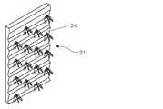
本実施形態に係る水耕栽培システム1は、レタス、グリーンリーフ、サラダ菜、ミズ菜、ホウレンソウ、ハーブ類などの葉物野菜を栽培するのに特に好適であり、苗床で種から育てられた、これらの植物(栽培対象)の苗pが移植される栽培パネル21が縦に配置された水耕栽培ユニット2と、自然光を外部から採り入れて栽培パネル21に移植された苗pに光を照射する採光装置3とを備えている。 The hydroponic cultivation system 1 according to the present embodiment is particularly suitable for growing leafy vegetables such as lettuce, green leaf, salad vegetables, mizuna vegetables, spinach, herbs, and these grown on seedlings from seeds. A hydroponics unit 2 in which a
栽培パネル21としては、例えば、ポリスチレン、ポリプロピレン、ポリエチレン、ポリウレタン等の合成樹脂からなるボード(発泡ボードを含む)、植物繊維、樹脂繊維、無機繊維等の繊維素材からなる繊維ボード、木材などを用いることができるが、軽量であるとともに、生育した栽培対象Pの重さに耐え得る強度を有していれば、特に限定されない。 As the
栽培パネル21には、移植された苗pを保持する複数の植え付け孔22が穿設されている。これらの植え付け孔22は、栽培対象Pの収穫期の大きさを考慮した適切な間隔で配列されているとともに、パネル面に対して一定の角度をもって穿設されている。後述するようにして栽培パネル21の液肥供給面24に液肥を供給する際に、栽培パネル21の栽培面23側に液肥が回り込んで、栽培対象Pの根以外の部分に液肥が触れてしまわないようにするために、この角度θは、20〜50°とするのが好ましい(図3参照)。
特に図示しないが、栽培パネル21に苗pを移植するには、例えば、小片に切り出されたスポンジ状の苗床で苗pを生育させて、そのような苗床ごと植え付け孔22に保持させるなどすればよい。The
Although not specifically illustrated, in order to transplant the seedling p into the
また、栽培パネル21は、一方のパネル面が栽培面23とされ、他方のパネル面が液肥供給面24とされている。栽培パネル21に苗pを移植するには、その根が液肥供給面24に添って成長していくように移植され、液肥供給面24の上方に配設された液肥供給パイプ25から供給された液肥(固形又は液状の肥料を水に溶かした液体肥料)が、液肥供給面24を伝わって移植された苗pの根に行き渡るようにする。 The
特に図示しないが、液肥供給パイプ25には、その内部を流れる液肥が、栽培パネル21の液肥供給面24に向けて流下するように複数の小孔が穿設されている。そして、その配置や開口面積とともに、液肥の流量、流速を適宜調整することで、それぞれの栽培パネル21の液肥供給面24に均一に液肥を供給できるようになっている。 Although not particularly illustrated, the liquid
ここで、前述した特許文献1の水耕システムでは、液肥をミスト状に噴霧しており、本実施形態にあっても、苗pの根に液肥をミスト状に噴霧してもよいが、このようにした場合、目詰まりしないようにメンテナンスに気を付けなければならない。このため本実施形態では、上記のようにして苗pの根に液肥を供給するのが好ましく、このようにすることで、より簡易で、かつ、メンテナンスも容易な設備で液肥を供給することができる。 Here, in the hydroponic system of Patent Document 1 described above, liquid fertilizer is sprayed in a mist form, and even in this embodiment, liquid fertilizer may be sprayed on the roots of the seedling p in a mist form. If you do this, you must be careful about maintenance so as not to be clogged. For this reason, in this embodiment, it is preferable to supply liquid fertilizer to the roots of the seedling p as described above. By doing so, it is possible to supply liquid fertilizer with simpler and easier maintenance. it can.
また、栽培パネル21を横に配置すると、苗pに液肥を供給するために液肥を貯えておく栽培ベッドを用意しなければならず、重量物である栽培ベッドを支持するための構造が必要になる。これに対して、栽培パネル21を縦に配置して、上記のようにして苗pの根に液肥を供給することで、そのような構造が不要となり、設備コストを削減することができるだけでなく、設備の重量増加を抑制することもできる。 In addition, when the
栽培パネル21の液肥供給面24には、移植された苗pの根に効率よく液肥が行き渡るように、凹凸形状を設けたり、根の近傍に液肥が滞留する液肥だまりを形成したりすることもできるが、液肥供給面24の具体的な形態は特に限定されない。 The liquid
例えば、図3に示すように、植え付け孔22の配列に沿って凸条22aを形成するとともに、液肥供給面24を裏面パネル24aで覆うようにしてもよい。このようにすることで、液肥供給面24に供給された液肥は、凸条22aに滞留しつつ裏面パネル24aとの隙間から流下するようになり、移植された苗pの根に効率よく液肥が行き渡るようにすることができる。
また、液肥供給面24には、図4に示すような傾斜面を組み合わせた凹凸形状を形成し、これらの傾斜面を伝わりながら流下する液肥が、移植された苗pの根に効率よく行き渡るようにしてもよい。For example, as shown in FIG. 3, while forming the protruding item |
Further, the liquid
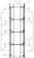
また、本実施形態では、このような栽培パネル21が縦に配置されていれば、栽培パネル21の具体的な配列などは特に限定されない。図示する例では、上下に複数段に組まれたフレームのそれぞれの段に設けられたガイドレール26に、縦に配置された複数の栽培パネル21が、横スライド可能に支持されて横方向に並んでいる(図2参照)。栽培パネル21を支持する段ごとに敷設されたガイドレール26には、栽培パネル21の横スライドを補助するローラー27を列設してもよい。 Moreover, in this embodiment, if such a
図示する例において、栽培パネル21の液肥供給面24に液肥を供給する液肥供給パイプ25は、段ごとに配設されており、栽培パネル21を支持するガイドレール26は、栽培パネル21の液肥供給面24を伝わって流下してきた液肥を受ける樋状に形成することができる。これとともに、樋状に形成したガイドレール26で受けた液肥を適宜調製して、液肥供給パイプ25に循環させて再利用することもできる。 In the illustrated example, the liquid
このように、本実施形態における水耕栽培ユニット2は、段ごとにガイドレール26に複数の栽培パネル21を横スライド可能に支持してなる栽培ブロック20を含み、上下に段状に形成された栽培ブロック20の集合体として構成される。そして、図2に示すように、栽培ブロック20ごとに、栽培対象Pの成長にあわせて栽培パネル21を横スライド(図2に示す例では、図中左側から右側に向かって横スライド)させていき、栽培対象Pが収穫期になった栽培パネル21を取り外すとともに、新たな苗pが移植された栽培パネル21をガイドレール26に支持していく作業を繰り返すことで、栽培対象Pを定期的に収穫できるようにしてある。 Thus, the hydroponics unit 2 in this embodiment includes the
ここで、特許文献1の水耕栽培システムでは、垂直に多段に構成したパネルを縦方向にスライドさせて、その入れ替え作業を行うようにしている。このため、最下段のパネルを取り外す際に、その上段に位置するパネルをストッパーで固定する作業が必要となり、最下段のパネルを取り外した後もパネルが落下しないように注意しながら全てのパネルを縦方向にスライドさせなければならず、煩雑な作業を要する。これに対して、本実施形態によれば、栽培パネル21を横スライド可能に支持して栽培ブロック20を構成するので、栽培パネル21の入れ替え作業が容易になる。
なお、図6は、栽培パネル21の入れ替え作業の様子を示す説明図である。Here, in the hydroponics system of patent document 1, the panel comprised in the perpendicular | vertical multistage is slid to the vertical direction, and the replacement | exchange operation | work is performed. For this reason, when removing the lowermost panel, it is necessary to fix the upper panel with a stopper, and after removing the lowermost panel, take care not to drop the panels. It must be slid in the vertical direction, which requires complicated work. On the other hand, according to this embodiment, since the
In addition, FIG. 6 is explanatory drawing which shows the mode of the replacement | exchange work of the
また、本実施形態において、水耕栽培ユニット2は、栽培パネル21の栽培面23が対向するようにして、二基の水耕栽培ユニット2が対をなして設置される。そして、対になった二基の水耕栽培ユニット2の間に、これらの水耕栽培ユニット2が備える栽培パネル21に移植された苗pに、自然光を外部から採り入れて光を照射する採光装置3が設置される。 Moreover, in this embodiment, the hydroponics unit 2 is installed so that the two hydroponics units 2 make a pair so that the
このような構成を基本構成として備える本実施形態の水耕栽培システム1は、栽培パネル21の栽培面23が対向するように設置された二基の水耕栽培ユニット2と、その間に設置された採光装置3とを構成単位とし、水耕栽培ユニット2が備える栽培パネル21の液肥供給面24側を突き合わせて複数の当該構成単位を並べて設置することができる。 The hydroponic cultivation system 1 of this embodiment having such a configuration as a basic configuration is installed between two hydroponic cultivation units 2 installed so that the
採光装置3は、それぞれの水耕栽培ユニット2が備える栽培パネル21の栽培面23と平行に立設された一対の反射板31aを有しており、かかる一対の反射板31aのそれぞれの対向面は、反射率が高められた反射面とされている。これにより、上方に位置する採光口30から採り入れられた自然光が、対向する反射板31aの間で反射を繰り返しながら下方に伝搬するようになっている。
なお、図示する例において、反射板31aは、フレームに立設された支柱35と、かかる支柱35と交叉して格子状に組まれた梁36とに固定されている。The
In the illustrated example, the reflecting
このような反射板31aとしては、例えば、その反射面となる面に、銀、銀合金、アルミニウム、多層フィルムなどからなる層が形成されて反射率が高められた、鋼板、アルミニウム板、アルミニウム合金板などの金属板を用いることができる。かかる金属板を用いて反射板31aを形成するにあたり、反射板31aは一枚の当該金属板から形成してもよく、複数の当該金属板を組み合わせて形成してもよい。 As such a reflecting
また、それぞれの反射板31aには、栽培パネル21の位置に応じて、複数の出射孔32が所定の開口率で穿設されている(図5参照)。これにより、採光口30から採り入れられた自然光が、反射板31aの反射面を繰り返し反射しながら伝搬する過程で、反射板31aに穿設された出射孔32から、栽培パネル21に移植された苗pにスポット的に光が照射されるようになっている。
なお、図5は、本実施形態に係る水耕栽培システムの概略を斜視して示す説明図であり、フレームなどを除いた主要構成部材のみを示している。Moreover, according to the position of the
In addition, FIG. 5 is explanatory drawing which shows the outline of the hydroponic cultivation system which concerns on this embodiment, and has shown only the main structural members except a flame | frame.
採光装置3の高さは、水耕栽培ユニット2の高さと同等又はそれ以上とし、採光口30から採り入れた自然光を上下に並ぶ栽培パネル21に移植された苗pに照射できるようにするが、横方向に並ぶ一又は二以上の栽培パネル21ごとに対応するように反射板31aを分割してもよい。 The height of the
また、採光装置3は、その底部側に、採光装置3内を伝搬して底部側に達した光を反射板31aに向けて反射する底部反射板31bを有している。底部反射板31bは、反射板31aに用いたのと同様の金属板を用いて、底部側に達した光が、対向するそれぞれの反射板31aに向かって均等に反射されるように、所定の角度をもった山なりに形成するのが好ましい。 Further, the
また、採光装置3は、その側部側に、側部からの光の漏洩を防ぐための側部反射板31cを有することが好ましい。側部反射板31cも、反射板31aと同様の金属板を用いて形成することができる。 Moreover, it is preferable that the
また、採光装置3から照射された光が、無駄なく栽培パネル21に移植された苗pに照射されるように、採光装置3と水耕栽培ユニット2との間の空間(栽培空間)の側部に、当該空間を囲う側部囲繞部材を設けるのが好ましい。側部囲繞部材を設けるには、図5に示すように、当該空間側の面が反射面とされた反射側板31dを側部反射板31cと並設してもよいが、採光装置3の側部反射板31cを水耕栽培ユニット2側に延長してもよい。後者の場合、水耕栽培システム1を構成する部材数が増えないため、部材管理や製造コストの面で有利である。 Moreover, the side of the space (cultivation space) between the
このようにすることで、栽培空間からの光の漏洩を抑制するともに、採光装置3と水耕栽培ユニット2との間に形成される栽培空間への二酸化炭素の供給や、その空調を効率よく行うことができる。 By doing in this way, while suppressing the leakage of the light from cultivation space, the supply of the carbon dioxide to the cultivation space formed between the
さらに、採光装置3から照射された光が、無駄なく栽培パネル21に移植された苗pに照射されるようにするには、反射板31aの栽培パネル21側の面も反射面とするのが好ましく、かかる反射面は、拡散反射面とするのがより好ましい。 Furthermore, in order for the light irradiated from the
このような本実施形態に係る水耕栽培システム1にあっては、栽培対象の苗pが移植される栽培パネル21を縦に配置することで、栽培面積を広くとることができ、収穫量を増やすことができる。さらに、栽培パネル21の栽培面23と平行に立設された一対の反射板31aを有する採光装置3により、採光口から採り入れられた自然光が、反射板31aの反射面を繰り返し反射しながら伝搬する過程で、かかる反射板31aに穿設された出射孔32から、栽培パネル21に移植された苗pに光が照射されるようにすることで、低コストかつ高栽培密度で栽培対象Pを効率よく育成することができる。 In the hydroponic cultivation system 1 according to this embodiment, by arranging the
また、採光装置3は、栽培パネル21の栽培面23と平行に立設された一対の反射板31aを有する縦型の採光装置として構成されており、採光口を建屋の天面に設置することができるため、太陽の位置に対する設置の自由度が高い。
なお、反射板を横置きにして採光装置を構成した場合、採光口を建屋の天面に設置すると、光を導くための付加的な導光手段が必要になり、システムの構造が複雑になってしまう。また、採光口を建物の壁面に設置すれば、そのような導光手段は必要なくなるが、太陽の位置よって採光できない時間が生じてしまう。The
When the daylighting device is configured with the reflector placed horizontally, if the daylighting port is installed on the top surface of the building, an additional light guiding means for guiding the light is required, which complicates the system structure. End up. Further, if the daylighting port is installed on the wall surface of the building, such a light guiding means is not necessary, but a time during which no daylight can be taken occurs depending on the position of the sun.
このように、本実施形態によれば、栽培パネル21を縦に配置するともに、この栽培パネル21の栽培面23と平行に立設された一対の反射板31aを有する採光装置3によりシステムを構築することで、簡易なシステム構成で、低コストかつ高栽培密度で栽培対象Pを効率よく育成することができる。 Thus, according to this embodiment, while arrange | positioning the
[第二実施形態]
次に、本発明に係る水耕栽培システムの第二実施形態について説明する。[Second Embodiment]
Next, a second embodiment of the hydroponic cultivation system according to the present invention will be described.
本実施形態にあっては、図7及び図8に示すように、水耕栽培ユニット2が備える栽培パネル21の栽培面23と平行に立設された一対の反射板31aのそれぞれが、水耕栽培ユニット2に対する近接位置から離間位置に移動可能としている。
ここで、図7に示す例は、反射板31aが水耕栽培ユニット2に対する近接位置にある状態を示し、図8に示す例は、一方の反射板31aが水耕栽培ユニット2に対する離間位置にある状態を示している。In this embodiment, as shown in FIG.7 and FIG.8, each of a pair of
Here, the example shown in FIG. 7 shows a state in which the reflecting
これらの図に示す例において、反射板31aは、レール33上を移動する台車34に立設された支柱35と、かかる支柱35と交叉して格子状に組まれた梁36とに固定されて、水耕栽培ユニット2に対する近接位置から離間位置に移動可能とされている。
また、反射板31aの転倒を防止するために、反射板31aの上端側には、水耕栽培ユニット2側に向かって垂直に張り出す支持部材37を固定しておき、かかる支持部材37をフレーム側に固定したガイド部材38にスライド可能に支持するようにしている。In the examples shown in these drawings, the reflecting
Further, in order to prevent the reflecting
水耕栽培ユニット2に対して反射板31aを離間させることで、水耕栽培ユニット2をメンテナンスする際の作業スペースを確保することができる。さらに、成長した栽培対象Pが反射板31aに接触してしまわないように、栽培対象Pの成長にあわせて、栽培対象Pへの光の照射量ができるだけ減少しないようにしながら、反射板31aを徐々に栽培対象Pから離間さていくこともできる。また、水耕栽培ユニット2と反射板31aとの間隔が狭いと、その間に空気が滞留して、栽培対象Pの生育に必要な二酸化炭素が不足してしまったり、温度が偏ったりしてしまうなどの不具合が懸念される。このような不具合を抑止するために、必要に応じて、水耕栽培ユニット2に対して反射板31aを離間させて所定の空間を確保することによって、通気性を良くして空気の循環を促すようにすることもできる。 By separating the
このように、一対の反射板31aのそれぞれが、水耕栽培ユニット2に対する近接位置から離間位置に移動可能とするにあたり、底部反射板31bは、反射板31aに用いたのと同様の金属板を頂部で屈曲可能となるように所定の角度をもって山なりに組み合わせることによって形成し、一対の反射板31aのうち少なくとも一方を栽培ユニット2に対して離間させる際に、屈曲しながら頂部がせり上がっていくようにすることで、反射板31aの移動を妨げないようにするのが好ましい(図8参照)。 As described above, when each of the pair of reflecting
また、採光装置3の側部側に、側部反射板31cを設けるにあたっては、一方の反射板31aを水耕栽培ユニット2に対して離間させて、水耕栽培ユニット2との間に作業スペースを確保する際に、当該作業スペースに作業者が立ち入ることができるように、一方又は両方の側部反射板31cを引き戸状、又は開き戸状に開閉できるようするのが好ましい。 Further, when the
本実施形態が前述した第一実施形態と異なるのは、以上の点であり、それ以外は同様の構成を備えているので、他の構成についての詳細な説明は省略する。 This embodiment is different from the first embodiment described above in the above points, and the other configurations are the same as those in the first embodiment, and thus detailed description of other configurations is omitted.
以上、本発明について、好ましい実施形態を示して説明したが、本発明は、前述した実施形態に限定されるものではなく、本発明の範囲で種々の変更実施が可能であることはいうまでもない。 Although the present invention has been described with reference to the preferred embodiments, the present invention is not limited to the above-described embodiments, and various modifications can be made without departing from the scope of the present invention. Absent.
例えば、本発明によれば、自然光を採り入れて栽培対象Pに光を照射することで、低コストかつ高栽培密度で栽培対象Pを効率よく育成することができるが、このような本発明の効果を著しく損なわない範囲で、蛍光灯、発光ダイオード、有機ELなどの人工的な光源を補助的に併用することもできる。 For example, according to the present invention, it is possible to efficiently grow the cultivation target P at low cost and high cultivation density by adopting natural light and irradiating the cultivation target P with light. An artificial light source such as a fluorescent lamp, a light emitting diode, or an organic EL can be used in an auxiliary manner within a range that does not significantly impair the brightness.
また、自然光を採り入れて栽培対象Pに光を照射する採光装置3には、採光量を向上させるために、太陽光追尾装置や集光レンズなどを設けてもよい。 Moreover, in order to improve the amount of light collection, you may provide a sunlight tracking apparatus, a condensing lens, etc. in the
本発明は、植物工場において栽培対象を高栽培密度で効率よく育成する水耕栽培システムとして好適に利用することができる。 INDUSTRIAL APPLICABILITY The present invention can be suitably used as a hydroponics system that efficiently grows a cultivation target at a high cultivation density in a plant factory.
1 水耕栽培システム
2 水耕栽培ユニット
20 栽培ブロック
21 栽培パネル
22 植え付け孔
23 栽培面
26 ガイドレール
3 採光装置
30 採光口
31a 反射板
31b 底部反射板
31c 側部反射板
31d 反射側板
32 出射孔
P 栽培対象
p 苗DESCRIPTION OF SYMBOLS 1 Hydroponics system 2
Claims (5)
Translated fromJapanese自然光を外部から採り入れて前記栽培パネルに移植された苗に照射する採光装置と
を備え、
前記採光装置が、前記水耕栽培ユニットが備える前記栽培パネルの栽培面と平行に立設された一対の反射板を有し、
採光口から採り入れられた自然光が、前記反射板の対向する反射面を繰り返し反射しながら伝搬する過程で、前記反射板に穿設された出射孔から、前記栽培パネルに移植された苗に光を照射するように構成されるとともに、
前記反射板のそれぞれが、前記水耕栽培ユニットに対する近接位置から離間位置に移動可能とされ、
前記採光装置が、内部を伝搬して底部側に達した光を前記反射板に向けて反射する底部反射板を有し、
前記底部反射板が、頂部で屈曲可能となるように所定の角度をもって山なりに形成され、前記反射板のうち少なくとも一方を前記栽培パネルに対して離間させる際に、屈曲しながら頂部がせり上がることを特徴とする水耕栽培システム。Hydroponic cultivation unit in which the cultivation panel where the seedling to be cultivated is transplanted is arranged vertically,
A daylighting device for taking natural light from the outside and irradiating the seedlings transplanted to the cultivation panel;
The lighting device has a pair of reflectors erected in parallel with the cultivation surface of the cultivation panel included in the hydroponic cultivation unit,
In the process in which natural light taken from the lighting port propagates while repeatedly reflecting the opposing reflecting surfaces of the reflecting plate, light is emitted from the emission holes drilled in the reflecting plate to the seedlings transplanted to the cultivation panel.Configured to irradiate,
Each of the reflectors is movable from a proximity position to the hydroponics unit to a separation position,
The daylighting device has a bottom reflector that reflects the light propagating through the interior and reaching the bottom to the reflector;
The bottom reflector is formed in a mountain with a predetermined angle so that it can be bent at the top, and when the at least one of the reflectors is separated from the cultivation panel, the top rises while bending. Hydroponic cultivation system characterized by that.
Priority Applications (8)
| Application Number | Priority Date | Filing Date | Title |
|---|---|---|---|
| JP2014224934AJP6467872B2 (en) | 2014-11-05 | 2014-11-05 | Hydroponics system |
| SG11201703236XASG11201703236XA (en) | 2014-11-05 | 2015-09-29 | Hydroponic system |
| US15/524,302US10412908B2 (en) | 2014-11-05 | 2015-09-29 | Hydroponic system |
| CN201580056154.5ACN107072157B (en) | 2014-11-05 | 2015-09-29 | Hydroponic cultivation system |
| PCT/JP2015/004922WO2016072042A1 (en) | 2014-11-05 | 2015-09-29 | Hydroponic system |
| EP15856953.3AEP3216342B1 (en) | 2014-11-05 | 2015-09-29 | Hydroponic system |
| MYPI2017701411AMY186488A (en) | 2014-11-05 | 2015-09-29 | Hydroponic system |
| PH12017500657APH12017500657A1 (en) | 2014-11-05 | 2017-04-07 | Hydroponic system |
Applications Claiming Priority (1)
| Application Number | Priority Date | Filing Date | Title |
|---|---|---|---|
| JP2014224934AJP6467872B2 (en) | 2014-11-05 | 2014-11-05 | Hydroponics system |
Publications (2)
| Publication Number | Publication Date |
|---|---|
| JP2016086734A JP2016086734A (en) | 2016-05-23 |
| JP6467872B2true JP6467872B2 (en) | 2019-02-13 |
Family
ID=55908790
Family Applications (1)
| Application Number | Title | Priority Date | Filing Date |
|---|---|---|---|
| JP2014224934AActiveJP6467872B2 (en) | 2014-11-05 | 2014-11-05 | Hydroponics system |
Country Status (8)
| Country | Link |
|---|---|
| US (1) | US10412908B2 (en) |
| EP (1) | EP3216342B1 (en) |
| JP (1) | JP6467872B2 (en) |
| CN (1) | CN107072157B (en) |
| MY (1) | MY186488A (en) |
| PH (1) | PH12017500657A1 (en) |
| SG (1) | SG11201703236XA (en) |
| WO (1) | WO2016072042A1 (en) |
Families Citing this family (22)
| Publication number | Priority date | Publication date | Assignee | Title |
|---|---|---|---|---|
| CA2942416A1 (en)* | 2014-03-18 | 2015-09-24 | Heath William BAX | Downpipe assembly |
| JP6862682B2 (en)* | 2016-05-30 | 2021-04-21 | 東洋製罐グループホールディングス株式会社 | Hydroponics system, hydroponics control device, hydroponics method and program |
| US10863679B2 (en)* | 2016-09-08 | 2020-12-15 | Fork Farms Holdings, Llc | Modular plant growth apparatus |
| CH713118A1 (en)* | 2016-11-10 | 2018-05-15 | Erika Glesser Lott | Greenhouse with light deflection device. |
| USD886332S1 (en)* | 2017-01-30 | 2020-06-02 | Metal Sales & Service, Inc. | Architectural wall cladding |
| JP7080013B2 (en)* | 2017-02-28 | 2022-06-03 | 東洋鋼鈑株式会社 | Hydroponics system and hydroponics method |
| US10660282B1 (en)* | 2017-04-08 | 2020-05-26 | Taylor MichaelMason Parrish | Horticulture apparatus and method |
| US20180325039A1 (en)* | 2017-05-15 | 2018-11-15 | Mark Munro Davison | Device for vertical cultivation of plants and method thereof |
| ES2895175T3 (en)* | 2017-05-30 | 2022-02-17 | Fraunhofer Ges Forschung | Device and method for promoting plant growth |
| US12284954B2 (en) | 2017-05-30 | 2025-04-29 | Fraunhofer-Gesellschaft Zur Foerderung Der Angewandten Forschung E.V. | Device for promoting the growth of plants |
| US11767995B2 (en)* | 2017-07-28 | 2023-09-26 | Biophilia Australia Pty Ltd | Movable ventilation system |
| JP6488052B1 (en)* | 2018-07-19 | 2019-03-20 | 藤澤建機株式会社 | Cultivation method, cultivation equipment, and cultivation apparatus |
| FR3094232B1 (en) | 2018-10-23 | 2023-09-29 | Capsum | MANUFACTURING UNIT FOR AN EXTRACT OF INTEREST OF AT LEAST ONE PLANT, MICROORGANISM AND/OR FUNGUS |
| US11730090B2 (en)* | 2019-02-25 | 2023-08-22 | Freight Farms, Inc. | Closed farm system with air flow control |
| USD906164S1 (en)* | 2019-08-07 | 2020-12-29 | Conrad Simard | Plant growing table |
| US11707027B2 (en) | 2019-12-02 | 2023-07-25 | Fork Farms Holdings, Llc | Hydroponic grow assembly |
| US20230025874A1 (en)* | 2019-12-20 | 2023-01-26 | 2327100 Alberta Inc. | Modular plant growth system |
| US11877548B2 (en) | 2020-09-24 | 2024-01-23 | Cyclofields Indoor Farming | Closed loop vertical disengageable aeroponic growing system |
| FR3120493B1 (en)* | 2021-03-15 | 2023-05-05 | Vert Tical Nord | Modular culture support for vegetated wall promoting runoff |
| AU2021479214A1 (en)* | 2021-12-17 | 2024-07-18 | CHIA, Bee Hua | An aquaponic system and a method of arranging beds of a plurality of frames of the aquaponic system |
| CN114793873A (en)* | 2022-05-10 | 2022-07-29 | 内蒙古罗欧农业有限公司 | A potato aeroponics structure and aeroponics equipment |
| FR3145288A1 (en) | 2023-01-31 | 2024-08-02 | Capsum | Process for extracting an extract of interest from at least one plant and/or mushroom |
Family Cites Families (14)
| Publication number | Priority date | Publication date | Assignee | Title |
|---|---|---|---|---|
| CN1088383A (en) | 1992-12-21 | 1994-06-29 | 陈少勇 | Cupboard type extendible stair shape vegetable production machine |
| JPH08331991A (en)* | 1995-06-07 | 1996-12-17 | Q P Corp | Plant cultivation equipment |
| JPH0998665A (en)* | 1995-07-28 | 1997-04-15 | Mitsubishi Chem Corp | Plant cultivation equipment |
| US6000173A (en)* | 1998-08-05 | 1999-12-14 | Schow; Matthew Alan | Hydroponic growing station with intermittent nutrient supply |
| JP4148575B2 (en)* | 1998-11-02 | 2008-09-10 | 株式会社日建設計 | Optical duct device |
| AU2319900A (en) | 1999-01-27 | 2000-08-18 | Seiichi Marumoto | Ultra-high-density plant vertical mist hydroponic system and raising panel |
| JP2000217451A (en)* | 1999-02-02 | 2000-08-08 | Kannax:Kk | Apparatus for water culture |
| JP2004097172A (en)* | 2002-09-13 | 2004-04-02 | Nikken Sekkei Ltd | Plant growing plant using light duct |
| KR101240249B1 (en)* | 2011-02-17 | 2013-03-07 | 박영환 | Plant growing system |
| JP5938653B2 (en)* | 2012-05-11 | 2016-06-22 | パナソニックIpマネジメント株式会社 | Pest control lighting system |
| US20140144079A1 (en)* | 2012-11-28 | 2014-05-29 | Ming-Tsun LIN | Plant culturing equipment |
| CN203136711U (en) | 2013-03-28 | 2013-08-21 | 王雅婧 | Full-automatic circulation dry land soilless multistoried planting device |
| US10098287B2 (en)* | 2014-06-06 | 2018-10-16 | RackREIT, LLC | System and method for cultivating plants |
| WO2016191596A1 (en)* | 2015-05-26 | 2016-12-01 | Delos Living Llc | Green wall modular system |
- 2014
- 2014-11-05JPJP2014224934Apatent/JP6467872B2/enactiveActive
- 2015
- 2015-09-29USUS15/524,302patent/US10412908B2/ennot_activeExpired - Fee Related
- 2015-09-29WOPCT/JP2015/004922patent/WO2016072042A1/enactiveApplication Filing
- 2015-09-29EPEP15856953.3Apatent/EP3216342B1/enactiveActive
- 2015-09-29CNCN201580056154.5Apatent/CN107072157B/ennot_activeExpired - Fee Related
- 2015-09-29MYMYPI2017701411Apatent/MY186488A/enunknown
- 2015-09-29SGSG11201703236XApatent/SG11201703236XA/enunknown
- 2017
- 2017-04-07PHPH12017500657Apatent/PH12017500657A1/enunknown
Also Published As
| Publication number | Publication date |
|---|---|
| JP2016086734A (en) | 2016-05-23 |
| EP3216342A4 (en) | 2018-06-06 |
| WO2016072042A1 (en) | 2016-05-12 |
| PH12017500657A1 (en) | 2017-10-02 |
| EP3216342B1 (en) | 2020-06-24 |
| US10412908B2 (en) | 2019-09-17 |
| MY186488A (en) | 2021-07-22 |
| CN107072157A (en) | 2017-08-18 |
| SG11201703236XA (en) | 2017-05-30 |
| US20170311560A1 (en) | 2017-11-02 |
| EP3216342A1 (en) | 2017-09-13 |
| CN107072157B (en) | 2020-11-06 |
Similar Documents
| Publication | Publication Date | Title |
|---|---|---|
| JP6467872B2 (en) | Hydroponics system | |
| KR102642440B1 (en) | Automated modular system for managing vertical farms | |
| KR102226531B1 (en) | Hydroponic Culture System, and Plant Factory Provided with Hydroponic Culture System and Greenhouse Produced from Styrene Foam | |
| US10098287B2 (en) | System and method for cultivating plants | |
| US11483981B1 (en) | Systems and methods for providing a low energy use farm | |
| KR101240249B1 (en) | Plant growing system | |
| JP4589773B2 (en) | Three-dimensional hydroponics equipment | |
| JP6758731B2 (en) | Growth device and growth method of plants or fungi | |
| JP6814589B2 (en) | Plant growth promotion device, plant growth promotion system using the plant growth promotion device, and plant growth promotion method | |
| WO2010073901A1 (en) | Hydroponic method for leaf vegetables and hydroponic unit | |
| JP5330162B2 (en) | Closed plant factory | |
| US20180168110A1 (en) | Facilities and method for cultivating plants | |
| JP2006262750A5 (en) | ||
| JP2008245554A (en) | Three-dimensional multistage type plant-cultivating device | |
| JP2014033622A (en) | Plant cultivation device and plant cultivation method | |
| KR20090088668A (en) | Sprout cultivation device using trolley conveyor | |
| JP3190912U (en) | Hydroponics equipment | |
| KR101892541B1 (en) | Lighting fixtures for greenhouse | |
| JP2015073511A (en) | Plant cultivation apparatus | |
| WO2019117008A1 (en) | Plant cultivation system and plant cultivation method | |
| JP7687654B2 (en) | plant cultivation equipment | |
| JPH01235524A (en) | Fully controlled plant factory | |
| JP2020137431A (en) | Nutrient solution supply equipment, plant cultivation system, and nutrient solution supply program | |
| KR100533457B1 (en) | movable traveling apparatus with plant photosynthesis promotion lamp | |
| KR20210053566A (en) | Lighting fixtures for greenhouse |
Legal Events
| Date | Code | Title | Description |
|---|---|---|---|
| RD01 | Notification of change of attorney | Free format text:JAPANESE INTERMEDIATE CODE: A7421 Effective date:20170630 | |
| A621 | Written request for application examination | Free format text:JAPANESE INTERMEDIATE CODE: A621 Effective date:20171018 | |
| A131 | Notification of reasons for refusal | Free format text:JAPANESE INTERMEDIATE CODE: A131 Effective date:20181009 | |
| A521 | Request for written amendment filed | Free format text:JAPANESE INTERMEDIATE CODE: A523 Effective date:20181204 | |
| TRDD | Decision of grant or rejection written | ||
| A01 | Written decision to grant a patent or to grant a registration (utility model) | Free format text:JAPANESE INTERMEDIATE CODE: A01 Effective date:20181218 | |
| A61 | First payment of annual fees (during grant procedure) | Free format text:JAPANESE INTERMEDIATE CODE: A61 Effective date:20181231 | |
| R150 | Certificate of patent or registration of utility model | Ref document number:6467872 Country of ref document:JP Free format text:JAPANESE INTERMEDIATE CODE: R150 |