JP6467744B2 - A method that allows to generate an ideal curvature of a rod of vertebral joint material designed to support a patient's spine - Google Patents
A method that allows to generate an ideal curvature of a rod of vertebral joint material designed to support a patient's spineDownload PDFInfo
- Publication number
- JP6467744B2 JP6467744B2JP2016543478AJP2016543478AJP6467744B2JP 6467744 B2JP6467744 B2JP 6467744B2JP 2016543478 AJP2016543478 AJP 2016543478AJP 2016543478 AJP2016543478 AJP 2016543478AJP 6467744 B2JP6467744 B2JP 6467744B2
- Authority
- JP
- Japan
- Prior art keywords
- rod
- apex
- point
- defining
- spine
- Prior art date
- Legal status (The legal status is an assumption and is not a legal conclusion. Google has not performed a legal analysis and makes no representation as to the accuracy of the status listed.)
- Expired - Fee Related
Links
Images


Classifications
- G—PHYSICS
- G06—COMPUTING OR CALCULATING; COUNTING
- G06F—ELECTRIC DIGITAL DATA PROCESSING
- G06F30/00—Computer-aided design [CAD]
- A—HUMAN NECESSITIES
- A61—MEDICAL OR VETERINARY SCIENCE; HYGIENE
- A61B—DIAGNOSIS; SURGERY; IDENTIFICATION
- A61B17/00—Surgical instruments, devices or methods
- A61B17/56—Surgical instruments or methods for treatment of bones or joints; Devices specially adapted therefor
- A61B17/58—Surgical instruments or methods for treatment of bones or joints; Devices specially adapted therefor for osteosynthesis, e.g. bone plates, screws or setting implements
- A61B17/68—Internal fixation devices, including fasteners and spinal fixators, even if a part thereof projects from the skin
- A61B17/70—Spinal positioners or stabilisers, e.g. stabilisers comprising fluid filler in an implant
- A61B17/7001—Screws or hooks combined with longitudinal elements which do not contact vertebrae
- A61B17/7002—Longitudinal elements, e.g. rods
- A61B17/7011—Longitudinal element being non-straight, e.g. curved, angled or branched
- A—HUMAN NECESSITIES
- A61—MEDICAL OR VETERINARY SCIENCE; HYGIENE
- A61B—DIAGNOSIS; SURGERY; IDENTIFICATION
- A61B34/00—Computer-aided surgery; Manipulators or robots specially adapted for use in surgery
- A61B34/10—Computer-aided planning, simulation or modelling of surgical operations
- A—HUMAN NECESSITIES
- A61—MEDICAL OR VETERINARY SCIENCE; HYGIENE
- A61B—DIAGNOSIS; SURGERY; IDENTIFICATION
- A61B17/00—Surgical instruments, devices or methods
- A61B17/56—Surgical instruments or methods for treatment of bones or joints; Devices specially adapted therefor
- A61B2017/568—Surgical instruments or methods for treatment of bones or joints; Devices specially adapted therefor produced with shape and dimensions specific for an individual patient
- A—HUMAN NECESSITIES
- A61—MEDICAL OR VETERINARY SCIENCE; HYGIENE
- A61B—DIAGNOSIS; SURGERY; IDENTIFICATION
- A61B34/00—Computer-aided surgery; Manipulators or robots specially adapted for use in surgery
- A61B34/10—Computer-aided planning, simulation or modelling of surgical operations
- A61B2034/101—Computer-aided simulation of surgical operations
- A61B2034/105—Modelling of the patient, e.g. for ligaments or bones
- A—HUMAN NECESSITIES
- A61—MEDICAL OR VETERINARY SCIENCE; HYGIENE
- A61B—DIAGNOSIS; SURGERY; IDENTIFICATION
- A61B34/00—Computer-aided surgery; Manipulators or robots specially adapted for use in surgery
- A61B34/10—Computer-aided planning, simulation or modelling of surgical operations
- A61B2034/108—Computer aided selection or customisation of medical implants or cutting guides
Landscapes
- Health & Medical Sciences (AREA)
- Engineering & Computer Science (AREA)
- Orthopedic Medicine & Surgery (AREA)
- Life Sciences & Earth Sciences (AREA)
- Surgery (AREA)
- General Health & Medical Sciences (AREA)
- Neurology (AREA)
- Veterinary Medicine (AREA)
- Public Health (AREA)
- Nuclear Medicine, Radiotherapy & Molecular Imaging (AREA)
- Animal Behavior & Ethology (AREA)
- Molecular Biology (AREA)
- Medical Informatics (AREA)
- Biomedical Technology (AREA)
- Heart & Thoracic Surgery (AREA)
- Physics & Mathematics (AREA)
- Theoretical Computer Science (AREA)
- Robotics (AREA)
- Evolutionary Computation (AREA)
- Geometry (AREA)
- General Engineering & Computer Science (AREA)
- General Physics & Mathematics (AREA)
- Computer Hardware Design (AREA)
- Prostheses (AREA)
- Surgical Instruments (AREA)
- Architecture (AREA)
- Software Systems (AREA)
Description
Translated fromJapanese本発明は、患者の脊柱をサポートするために設計された脊椎骨接合材料のロッドの理想的な湾曲を生成することを可能にする方法に関する。 The present invention relates to a method that makes it possible to generate an ideal curvature of a rod of vertebral joint material designed to support a patient's spine.
科学文献に文書化された、いわゆる「骨盤」パラメータおよび脊柱の異なる形態型に関して患者の脊柱を分析することは既知である。添付された図1は、脊柱の基部、すなわち腰椎Lおよび仙骨S、同じく大腿骨頭部TFの一部を非常に模式的に示す;上述した骨盤の判定基準は、以下の通りである:
−水平線に対するS1(仙骨の第1脊椎)のプレートの傾斜角度であるSS(仙骨傾斜角)判定基準;
−垂直線と大腿骨頭部TFの中心およびS1のプレートの中心を接続する直線セグメントとによって形成される角度であるPV(骨盤回転)判定基準;
−S1のプレートに対する垂直線と大腿骨頭部TFの中心およびS1のプレートの中心を接続する直線セグメントとによって形成される角度であるPI(骨盤形態角)判定基準。It is known to analyze a patient's spine with respect to the so-called “pelvis” parameters and the different morphological types of the spine documented in the scientific literature. The attached FIG. 1 very schematically shows the base of the spinal column, ie the lumbar vertebra L and sacrum S, also part of the femoral head TF; the criteria for the pelvis mentioned above are as follows:
-SS (sacral tilt angle) criterion, which is the tilt angle of the plate of S1 (first sacrum of the sacrum) with respect to the horizon;
A PV (pelvic rotation) criterion, which is the angle formed by the vertical line and the straight segment connecting the center of the femoral head TF and the center of the plate of S1;
A PI (Pelvic Form Angle) criterion, which is the angle formed by the normal to the S1 plate and the straight segment connecting the center of the femoral head TF and the center of the S1 plate.
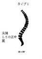
図2Aから2Dは、それぞれ:
−尖端(すなわち脊柱の最前方点)がL5(第5腰椎)の正中面に位置し、かつSS判定基準が35°より小さい角度に対応するいわゆる「タイプ1」形態型;
−尖端がL4(第4腰椎)の基部に位置し、かつSS判定基準が35°より小さい角度に対応するいわゆる「タイプ2」形態型;
−尖端がL4の正中面に位置し、かつSS判定基準が35°と45°の間に含まれる角度に対応するいわゆる「タイプ3」形態型;
−尖端がL3(第3腰椎)の基部に位置し、かつSS判定基準が45°より大きな角度に対応するいわゆる「タイプ4」形態型を示す。Figures 2A to 2D respectively show:
A so-called “type 1” morphological type in which the apex (ie the foremost point of the spinal column) is located in the midline of L5 (fifth lumbar vertebra) and the SS criterion corresponds to an angle of less than 35 °;
A so-called “type 2” morphological type whose apex is located at the base of L4 (fourth lumbar vertebra) and whose SS criterion corresponds to an angle of less than 35 °;
A so-called “type 3” morphological type whose tip is located on the midline of L4 and whose SS criterion corresponds to an angle comprised between 35 ° and 45 °;
-Denotes the so-called "type 4" morphological type, with the apex located at the base of L3 (third lumbar vertebra) and the SS criterion corresponding to an angle greater than 45 °.
人は、特に彼の骨盤パラメータが彼の背部形態型と一致している場合、痛覚および他の病状を回避する「実利的」と呼ばれる自然脊柱姿勢を採用することが認められる。そうでない場合、その一致が存在する脊柱の適切な姿勢を復旧するために外科治療が考慮されることができる。 It is recognized that a person adopts a natural spine posture called “utilitarian” that avoids pain and other medical conditions, especially when his pelvic parameters are consistent with his back morphologies. If this is not the case, surgical treatment can be considered to restore the proper posture of the spinal column where the match exists.
椎根ねじまたは薄層フックのような固定部材を使用して脊柱に固定される、特に金属でできた硬い脊椎ロッドを使用して、この種の復旧を施すことは周知であり、そのロッドは、実行されるべき補正に基づいて適切に湾曲されなければならない。(特許文献1)の刊行物が、この種の材料を例示する。 It is well known to provide this type of restoration using a rigid spinal rod, especially made of metal, which is fixed to the spinal column using a fixation member such as a pedicle screw or a lamellar hook, It must be properly curved based on the correction to be performed. The publication of US Pat. No. 6,057,086 exemplifies this type of material.
湾曲がロッドの任意の所定の位置でいくぶん顕著な、適切な湾曲をまっすぐなロッドに与えることは、外科医にとって非常に困難な場合があることが示されている。現在、この種の湾曲は外科医の裁量で実行され、かつ後者の経験および巧みさを大いに求める。適切な湾曲を得るのに必要な試行錯誤は、手術時間を延ばす重要な欠点を有し、それは患者にとって望ましくなく、および理想的でない湾曲を備えたロッドを埋め込む危険性が排除されることができない。 It has been shown that it may be very difficult for a surgeon to give a straight rod a proper curvature, where the curvature is somewhat pronounced at any given position on the rod. Currently, this type of curvature is performed at the surgeon's discretion and greatly seeks the latter experience and skill. The trial and error required to obtain the proper curvature has the important drawback of prolonging the operation time, which is undesirable for the patient and the risk of embedding a rod with a non-ideal curvature cannot be ruled out .
本発明は、この決定的な欠点を解消することを目的とする。 The present invention aims to overcome this critical drawback.
(特許文献2)、(特許文献3)および(特許文献4)は、この目的を満足に達成しない方法を記述する。 (Patent Document 2), (Patent Document 3), and (Patent Document 4) describe methods that do not satisfactorily achieve this goal.
そのために、本発明に従う方法は、以下の諸ステップを含む:
a)頸椎から大腿骨頭部まで伸びる、治療されるべき患者の脊柱の矢状方向手術前X線を撮るステップ;
b)そのX線に関して、以下を特定するステップ:
いわゆる「骨盤」パラメータ、すなわち仙骨傾斜角、骨盤回転および骨盤形態角、
腰椎前彎、
尖端にある腰椎の位置、すなわち前記X線上の最遠前方へ位置するそれの位置、
以下の測定値のうち少なくとも1つ:
S1と呼ばれる、仙骨の第1脊椎のプレートの後の上部点の垂直線から第7頸椎の中心を通過する垂直線までのSVAと呼ばれる距離;
S1のプレートの後の上部点の垂直線から大腿骨頭部の中心を通過する垂直線までのSFDと呼ばれる距離;
T1と呼ばれる第1胸椎の中心から、大腿骨頭部の中心に向かうセグメントとT1の中心に対する垂直線との間に形成されるT1/SPIと呼ばれる角度;
影響を受けた脊椎の上方プレートの中心に配置される、脊椎レベルあたり1点、および注記された手術前尖端を規定する点を含む患者の脊柱の湾曲を規定する点群;
c)所定の脊柱形態型の間でかつ仙骨傾斜角の注記された値から、治療された脊柱が対応する形態型を導き出し、かつそこから補正を施した後に所望の手術後尖端点を導き出し、かつ脊柱に固定されるべき脊椎ロッドに対して固定部材が埋め込まれる脊柱を規定するステップ;
d)例えばCADソフトウェアを使用して患者の脊柱のワイヤモデリングを行うステップ;
e)前記骨盤パラメータから、それの起点がそのプレートの中心点である、S1のプレートで中心におかれる基準を規定するステップ;
f)その基準で各脊椎に付属する前記点群の異なる点を配置し、かつ弧の全てが互いに接し、かつS1から伸びる弧がS1のプレートに対して垂直な直線に接する、特定された点の間に段階的に弧を描くステップ;
g)弧長の値を読みとるステップ;
h)次のように治療されるべき腰椎セグメントに適用されるべき補正をシミュレーションするステップ:
h1)所望の手術後尖端点に接する直線を描画し、その直線に付属する弧が所望の手術後尖端点に接し、手術後尖端点がモデル化された脊柱セグメントの尖端点になるように再配置されるように、その直線を垂直位置へ移動するステップ;
h2)その尖端点より上の一方および尖端点より下のもう一方の、2つの異なる湾曲を得るように、互いに共半径方向にその尖端点より下に位置する弧を規定し、かつ互いに共半径方向にその同じ尖端点より上に位置する弧を規定するステップ;
h3)骨盤傾斜角のプラスマイナス10度に等しいとして腰椎前彎を規定し、かつ要望どおり以下の3つの値のうち1つを規定するステップ:
− 5cmより小さいSVA距離;
− −1.9と+0.1の間に含まれるSVA/SFD比率;この比率の値は、大腿骨頭部の方へ位置するS1のプレートの後の上部点の垂直線の側で正であり、かつ大腿骨頭部の反対側に位置する垂直線の側で負である;
− −9°と0°の間に含まれるT1/SPI角度、その角度は大腿骨頭部の方へ位置するT1の中心の垂直線の側で負である;
h4)尖端点で互いに接し、それらの弧が、治療されるべき脊椎セグメントの補正を得るために、埋め込まれるべきロッドの理想的な湾曲を代表する湾曲セグメントを形成する、上記のステップh2中に得られる2つの湾曲に同軸の2つの弧を規定するステップ;
h5)前記湾曲セグメントの位置が、一旦埋め込まれたならばロッドがとる位置に対応するように、治療されるべき前記脊椎セグメントの脊柱にロッドを固定するための、固定部材の固定点に脊柱の中心から向かう評価平均距離にわたって、脊柱の平均線から離れてその湾曲セグメントを変形させるステップ;
i)埋め込まれるべきロッドの直径を規定するステップ;
j)前記湾曲セグメントに沿って湾曲するロッドの二次元または三次元モデルを規定するステップ、および
k)直線ロッドから、前記モデルに従ってそのロッドの湾曲を生成するステップ。To that end, the method according to the invention comprises the following steps:
a) taking a pre-sagittal x-ray of the spine of the patient to be treated extending from the cervical spine to the femoral head;
b) For that X-ray, the following steps arespecified :
The so-called “pelvic” parameters, ie sacral tilt angle, pelvic rotation and pelvic form angle,
Lumbar forehead,
The position of the lumbar spine at the apex, that is, the position farthest forward on the X-ray,
At least one of the following measurements:
The distance called SVA from the vertical line of the upper point behind the plate of the first vertebrae of the sacrum, called S1, to the vertical line passing through the center of the seventh cervical vertebra;
The distance called SFD from the vertical line of the upper point after the plate of S1 to the vertical line passing through the center of the femoral head;
An angle called T1 / SPI formed between a segment from the center of the first thoracic vertebra called T1 to the center of the femoral head and a perpendicular to the center of T1;
A point cloud defining the curvature of the patient's spine, including one point per spine level, and a point defining the noted preoperative tip, located in the center of the upper plate of the affected spine;
c) From the noted value of the sacral tilt angle between the given spinal column morphologies and deriving the corresponding morphological type to which the treated spine corresponds, and deriving from it, deriving the desired post-operative apex point; And defining a spinal column in which a fixation member is implanted relative to a spinal rod to be fixed to the spinal column;
d) performing wire modeling of the patient's spinal column, for example using CAD software;
e) from the pelvic parameters, defining a reference centered on the plate of S1, whose origin is the center of the plate;
f)Identified points that place different points of the point cloud attached to each spine on that basis, all of the arcs touch each other, and the arcs extending from S1 touch a straight line perpendicular to the plate of S1 Step by step arcing between the steps;
g) reading the arc length value;
h) Simulating the correction to be applied to the lumbar segment to be treated as follows:
h1) Draw a straight line that touches the desired post-surgical apex and re-establish the arc attached to the straight line so that it touches the desired post-surgical apex and the post-surgical apex becomes the apex of the modeled spinal segment. Moving the straight line to a vertical position so that it is positioned;
h2) defining arcs that are co-radial to each other below the apex and to be co-radial to each other so as to obtain two different curvatures, one above the apex and the other below the apex Defining an arc located in the direction above that same point;
h3) Defining the lumbar lordosis as being equal to plus or minus 10 degrees of pelvic tilt angle and defining one of the following three values as desired:
-SVA distance less than 5 cm;
-SVA / SFD ratio comprised between -1.9 and +0.1; the value of this ratio is positive on the vertical line side of the upper point after the plate of S1 located towards the femoral head And negative on the side of the vertical line located on the opposite side of the femoral head;
A T1 / SPI angle comprised between −9 ° and 0 °, which angle is negative on the side of the vertical line at the center of T1 located towards the femoral head;
h4) during step h2 above, where the arcs touch each other and their arcs form a curved segment representative of the ideal curvature of the rod to be implanted in order to obtain a correction of the spine segment to be treated Defining two arcs coaxial to the two curvatures obtained;
h5) The position of the vertebral column at the fixation point of the fixation member for fixing the rod to the vertebral column of the vertebral segment to be treated so that the position of the curved segment corresponds to the position taken by the rod once implanted Deforming the curved segment away from the average line of the spinal column over an estimated average distance from the center;
i) defining the diameter of the rod to be embedded;
j) defining a two-dimensional or three-dimensional model of the rod that curves along the curved segment, and k) generating a curvature of the rod from a straight rod according to the model.
好ましくは、前記所定の脊柱形態型は以下を含む:
−尖端(すなわち脊柱の最前方点)がL5(第5腰椎)の正中面に位置し、かつSS判定基準が35°より小さい角度に対応するいわゆる「タイプ1」形態型;
−尖端がL4(第4腰椎)の基部に位置し、かつSS判定基準が35°より小さい角度に対応するいわゆる「タイプ2」形態型;
−尖端がL4の正中面に位置し、かつSS判定基準が35°と45°の間に含まれる角度に対応するいわゆる「タイプ3」形態型;
−尖端がL3(第3腰椎)の基部に位置し、かつSS判定基準が45°より大きな角度に対応するいわゆる「タイプ4」形態型。Preferably, the predetermined spine morphologies include:
A so-called “type 1” morphological type in which the apex (ie the foremost point of the spinal column) is located in the midline of L5 (fifth lumbar vertebra) and the SS criterion corresponds to an angle of less than 35 °;
A so-called “type 2” morphological type whose apex is located at the base of L4 (fourth lumbar vertebra) and whose SS criterion corresponds to an angle of less than 35 °;
A so-called “type 3” morphological type whose tip is located on the midline of L4 and whose SS criterion corresponds to an angle comprised between 35 ° and 45 °;
The so-called “type 4” morphological type, with the apex located at the base of L3 (third lumbar vertebra) and the SS criterion corresponding to an angle greater than 45 °.
好ましくは、ステップj)で実行される二次元または三次元モデリングが、生成されるべきロッドの描画または平面図を確立することから成る。 Preferably, the two-dimensional or three-dimensional modeling performed in step j) consists of establishing a drawing or plan view of the rod to be generated.
好ましくは、ステップk)で生成される湾曲が、常温曲げによって実行される。 Preferably, the curvature generated in step k) is performed by cold bending.
好ましくは、この方法が、ステップh5)またはステップi)、またはステップj)の後、ロッドの湾曲を生成する役割を果たすサービス提供者への、生成されるべきロッドと関連するデータの転送を含む。 Preferably, the method comprises the transfer of data associated with the rod to be generated to a service provider responsible for generating the curvature of the rod after step h5) or step i) or step j). .
したがって、本発明に従う方法を使用して埋め込まれるべきロッドの形状を決定した開業医は、ロッドの湾曲を生成する役割を果たすサービス提供者に、生成されるべきロッドと関連するデータを転送する。一旦その湾曲が生成されたならば、サービス提供者が開業医に湾曲ロッドを供給し、開業医が患者に、埋め込まれる準備のできている患者の脊椎ロッドで手術を施すことが可能である。 Thus, the practitioner who has determined the shape of the rod to be implanted using the method according to the present invention forwards the data associated with the rod to be generated to the service provider responsible for generating the curvature of the rod. Once the curvature has been generated, the service provider can supply the practitioner with the curved rod, and the practitioner can perform surgery on the patient's spinal rod ready to be implanted.
本発明は、限定されない一例として、当該の方法を実行するのに用いられる異なる値およびその実現の状況で施される異なる手術を示す添付された図に関してよく理解され、かつそれの他の特徴および効果は明らかである。 The present invention is well understood with respect to the attached figures showing, by way of non-limiting example, different values used to perform the method and different operations performed in the context of its implementation, and other features and The effect is obvious.
図3は、脊柱CVを非常に模式的に示してかつ以下の情報を含む:
LL:治療されるべき脊椎セグメント;
L1、L2、L3、L4、L5、S1、C7:それぞれ第1、第2、第3、第4および第5腰椎、仙骨の第1脊椎および第7頸椎;
尖端:脊柱の最前方点;
SS、PV、PI:上述した骨盤判定基準;
TF:円によって示される大腿骨頭部;
H1およびV1:S1のプレートの後の上部点における、それぞれ水平および垂直線;
V2:第7頸椎(C7)の中心を通過する垂直線。FIG. 3 shows the spinal column CV very schematically and includes the following information:
LL: spine segment to be treated;
L1, L2, L3, L4, L5, S1, C7: first, second, third, fourth and fifth lumbar vertebrae, sacral first and seventh cervical vertebrae, respectively;
Apex: the foremost point of the spine;
SS, PV, PI: Pelvic criteria described above;
TF: femoral head indicated by a circle;
H1 and V1: horizontal and vertical lines, respectively, at the upper point after the S1 plate;
V2: A vertical line passing through the center of the seventh cervical vertebra (C7).
図4はさらに、垂直線V1から大腿骨頭部TFの中心を通過する垂直線に向かういわゆる「SFD」値に言及する。 FIG. 4 further refers to the so-called “SFD” value from the vertical line V1 to the vertical line passing through the center of the femoral head TF.
図5は、さらにいわゆる「T1/SPI」値に言及し、それはT1と呼ばれる第1胸椎の中心から大腿骨頭部TFの中心に向かうT1−TFセグメントとT1の中心への垂直線V3の間に形成される角度である。 FIG. 5 further refers to the so-called “T1 / SPI” value, which is between the T1-TF segment from the center of the first thoracic vertebra called T1 to the center of the femoral head TF and the vertical line V3 to the center of T1. The angle formed.
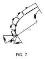
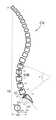
この方法の種々のステップが、次のように図6から11内に例示される。 The various steps of this method are illustrated in FIGS. 6 to 11 as follows.
図6:頸椎から大腿骨頭部まで伸びる、治療されるべき患者の脊柱の矢状方向手術前X線上で、以下が特定される:
骨盤パラメータ、
腰椎前彎、
尖端にある腰椎の位置、すなわち前記X線上の最遠前方へ位置するそれの位置、
要望どおり、SVA距離だけ、またはSVA距離およびSFD距離、
影響を受けた脊椎の上方プレートの中心に配置される、脊椎レベルあたり1点、および注記された手術前尖端を規定する点を含む患者の脊柱の湾曲を規定する点群。FIG. 6: On the pre-sagittal X-ray of the spine of the patient to be treated, extending from the cervical spine to the femoral head, the following isidentified :
Pelvic parameters,
Lumbar forehead,
The position of the lumbar spine at the apex, that is, the position farthest forward on the X-ray,
As required, SVA distance only, or SVA distance and SFD distance,
A point cloud that defines the curvature of the patient's spine, including one point per spinal level and a point defining the noted pre-operative apex, located in the center of the upper plate of the affected spine.
治療された脊柱が対応する形態型が図2Aから2D内に示される脊柱形態型の間で、注記された仙骨傾斜角の値から注記された点に導き出される;補正を施した後の所望の手術後尖端点が、そこから導き出される;脊柱に固定されるべき脊椎ロッドの固定部材が埋め込まれる脊柱が、さらにこのステップで規定される。 The morphological type to which the treated spine corresponds is derived from the noted sacral slope values to the noted point between the vertebral morphological types shown in FIGS. 2A to 2D; A post-operative apex point is derived therefrom; the spinal column into which the fixation member of the spinal rod to be fixed to the spinal column is implanted is further defined in this step.
図7および8:例えばCADソフトウェアを使用して患者の脊柱のワイヤモデルが実行される; Figures 7 and 8: A wire model of the patient's spine is performed, for example using CAD software;
図9:S1のプレートで中心におかれる基準が、前記骨盤パラメータから規定され、その基準の起点はそのプレートの中心点であり、次に各脊椎に付属する前記点群の異なる点がその基準に配置され、および特定された点間の弧が段階的に描画され、弧の全てが互いに接し、かつS1から伸びる弧がS1のプレートに対して垂直な直線に接する;
FIG. 9: The reference centered on the S1 plate is defined from the pelvic parameters, the starting point of the reference is the center point of the plate, and then the different points of the point cloud attached to each spine are the reference points. The arcs between thespecified points are drawn in stages, all of the arcs touch each other, and the arcs extending from S1 touch a straight line perpendicular to the plate of S1;
図10:弧長の値が読みとられ、および治療されるべき腰椎セグメントに適用されるべき補正が、次のようにシミュレーションされる:
所望の手術後尖端点に接する直線を描画し、その直線に付属する弧がその所望の手術後尖端点に接し、後者がしたがってモデル化された脊柱セグメントの尖端点になるように再配置されるように、その直線を垂直位置へ移動する、
その尖端点より上の一方およびその尖端点より下のもう一方の、2つの異なる湾曲を得るように、互いに共半径方向にその尖端点より下に位置する弧を規定し、かつ互いに共半径方向にその同じ尖端点より上に位置する弧を規定する、
腰椎前彎を骨盤傾斜角のプラスマイナス10度に等しいとして規定し、かつ要望どおり、3つの以下の値のうち1つを規定する:
− 5cmより小さいSVA距離;
− −1.9と+0.1の間に含まれるSVA/SFD比率;この比率の値は、大腿骨頭部TFの方へ位置する垂直線V1の側で正であり、かつ大腿骨頭部TFの反対側に位置するその垂直線V1の側で負である;
− −9°と0°の間に含まれるT1/SPI角度;この角度は、大腿骨頭部TFの方へ位置するT1の中心の垂直線V3の側で負である;
尖端点で互いに接する、上記のステップで得られる2つの湾曲に同軸の2つの弧を規定し、治療されるべき脊椎セグメントの補正を得るためにそれらの弧が、埋め込まれるべきロッドの理想的な湾曲を代表する湾曲セグメントSCを形成する。Figure 10: The arc length value is read and the correction to be applied to the lumbar segment to be treated is simulated as follows:
Draw a straight line tangent to the desired post-operative apex point and reposition the arc attached to that line so that it touches the desired post-operative apex point and the latter is therefore the apex point of the modeled spinal segment Move that straight line to a vertical position,
Define arcs that are co-radial to each other and below the point to obtain two different curves, one above the point and the other below the point, and co-radial to each other Defines an arc located above that same point,
Define the lumbar lordosis as being equal to plus or minus 10 degrees of pelvic tilt angle and, as desired, specify one of the following three values:
-SVA distance less than 5 cm;
-SVA / SFD ratio comprised between -1.9 and +0.1; the value of this ratio is positive on the side of the vertical line V1 located towards the femoral head TF and of the femoral head TF Negative on the side of its vertical line V1 located on the opposite side;
A T1 / SPI angle comprised between −9 ° and 0 °; this angle is negative on the side of the vertical line V3 at the center of T1 located towards the femoral head TF;
Define two arcs coaxial to the two curves obtained in the above steps that touch each other at the apex point, and these arcs are ideal for the rod to be implanted in order to obtain a correction for the spine segment to be treated A curved segment SC representative of the curvature is formed.
図11:湾曲セグメントSCは、前記湾曲セグメントSCの位置が、一旦埋め込まれたならばロッドが取る位置に対応するように、ロッドを治療されるべき前記脊椎セグメントの脊柱に固定するための、固定部材OA(図10、それは椎根ねじである)の固定点に、脊柱の中心から向かう評価平均距離にわたって脊柱の平均線から離れて変形される;埋め込まれるべきロッドの直径が規定され、前記弧に沿って湾曲するそのロッドの二次元または三次元モデルが、次いで確立される。 FIG. 11: The curved segment SC is fixed to secure the rod to the spinal column of the spinal segment to be treated so that the position of the curved segment SC corresponds to the position taken by the rod once implanted. At a fixed point of the member OA (FIG. 10, it is a pedicle screw), it is deformed away from the average line of the spine over an estimated average distance from the center of the spine; the diameter of the rod to be implanted is defined and A two-dimensional or three-dimensional model of the rod that curves along is then established.
図12:描画または平面図Pがそのモデルから確立され、次に特に常温曲げによって、得られるべき脊椎ロッドTVがその描画Pから配置される。 FIG. 12: A drawing or plan view P is established from the model, and then the spinal rod TV to be obtained is placed from the drawing P, in particular by cold bending.
本発明に従う方法は、したがって患者の脊柱をサポートするために設計された脊椎骨接合材料に対してロッドの理想的な湾曲を生成することを可能にする決定的な利点を有する。 The method according to the invention thus has the decisive advantage of allowing an ideal curvature of the rod to be generated for a vertebral joint material designed to support the patient's spine.
Claims (5)
Translated fromJapanesea)頸椎から大腿骨頭部まで伸びる、治療されるべき前記患者の前記脊柱の矢状方向手術前X線を撮るステップ;
b)前記X線に関して:
骨盤パラメータ、すなわち仙骨傾斜角、骨盤回転および骨盤形態角を特定し、
腰椎前彎を特定し、
尖端にある腰椎の位置、すなわち前記X線上の最遠前方へ位置するそれの位置を特定し、
以下の測定値の少なくとも1つを特定し、:
S1と呼ばれる、前記仙骨の第1脊椎のプレートの後の上部点の垂直線から第7頸椎の中心を通過する垂直線までのSVAと呼ばれる距離;
前記S1のプレートの後の上部点の垂直線から前記大腿骨頭部の中心を通過する垂直線までのSFDと呼ばれる距離;
T1と呼ばれる第1胸椎の中心から前記大腿骨頭部の中心に向かうセグメントとT1の中心に対する垂直線との間に形成されるT1/SPIと呼ばれる角度、
影響を受けた脊椎の上方プレートの中心に配置される、脊椎レベルあたり1点および注記された手術前尖端を規定する点を含む、前記患者の脊柱の湾曲を規定する点群を特定する、ステップ;
c)所定の脊柱形態型の間でかつ前記仙骨傾斜角の注記された値から治療された脊柱が対応する前記形態型を導き出し、かつそこから補正を施した後に所望の手術後尖端点を導き出し、かつ前記脊柱に固定されるべき脊椎ロッドに対して固定部材が埋め込まれる前記脊柱を規定するステップ;
d)CADソフトウェアを使用して前記患者の脊柱のワイヤモデリングを行うステップ;
e)前記骨盤パラメータから、前記S1のプレートで中心におかれる、それの起点が前記プレートの中心点である基準を規定するステップ;
f)前記基準において、各脊椎に付属する前記点群の異なる点を配置し、かつ弧の全てが互いに接し、かつS1から伸びる前記弧が前記S1のプレートに対して垂直な直線に接する、特定された点の間に段階的に前記弧を描画するステップ;
g)前記弧長の値を読みとるステップ;
h)次のように治療されるべき腰椎セグメントに適用されるべき前記補正をシミュレーションするステップ:
h1)所望の手術後尖端点に接する直線を描画し、前記直線に付属する前記弧が前記所望の手術後尖端点に接し、手術後尖端点がモデル化された脊柱セグメントの尖端点になるように再配置されるように、前記直線を垂直位置へ移動するステップ;
h2)前記尖端点より上の一方および尖端点より下のもう一方の、2つの異なる湾曲を得るように、互いに共半径方向に前記尖端点より下に位置する前記弧を規定し、かつ互いに共半径方向に前記同じ尖端点より上に位置する前記弧を規定するステップ;
h3)前記骨盤形態角のプラスマイナス10度に等しいとして前記腰椎前彎を規定し、かつ要望どおり以下の3つの値のうち1つを規定するステップ:
− 5cmより小さいSVA距離;
− −1.9と+0.1の間に含まれるSVA/SFD比率;前記比率の値は、前記大腿骨頭部の方へ位置する前記S1のプレートの後の上部点の垂直線の側で正であり、かつ前記大腿骨頭部の反対側に位置する垂直線の側で負である;
− −9°と0°の間に含まれるT1/SPI角度、前記角度は前記大腿骨頭部の方へ位置するT1の中心の垂直線の側で負である;
h4)前記尖端点で互いに接し、前記2つの弧が、前記治療されるべき脊椎セグメントの前記補正を得るために、前記埋め込まれるべきロッドの理想的な湾曲を代表する湾曲セグメントを形成する、上記のステップh2中に得られる2つの湾曲に同軸の2つの弧を規定するステップ;
h5)前記湾曲セグメントの位置が、一旦埋め込まれたならば前記ロッドが取る位置に対応するように、治療されるべき前記脊椎セグメントの前記脊柱に前記ロッドを固定するための、固定部材の固定点に前記脊柱の中心から向かう評価平均距離にわたって前記脊柱の平均線から離れて前記湾曲セグメントを変形させるステップ;
i)前記埋め込まれるべきロッドの直径を規定するステップ;
j)前記湾曲セグメントに沿って湾曲する前記ロッドの二次元または三次元モデルを規定するステップ;および
k)直線ロッドから、前記モデルに従って前記ロッドの湾曲を生成するステップ;を含む方法。A method that makes it possible to generate an ideal curvature of a rod of vertebral joint material designed to support a patient's spinal column, comprising the following steps:
a) taking a pre-sagittal x-ray of the spine of the patient to be treated extending from the cervical spine to the femoral head;
b) Regarding the X-ray:
Identify pelvic parameters, ie sacral tilt angle, pelvic rotation and pelvic form angle,
Identify the lumbar lordosis,
Identify the position of the lumbar spine at the apex, that is, the position that is located farthest forward on the X-ray,
Identify at least one of the following measurements:
The distance called SVA from the vertical line of the upper point behind the plate of the first vertebrae of the sacrum, called S1, from the vertical line passing through the center of the seventh cervical vertebra;
The distance called SFD from the vertical line of the upper point after the plate of S1 to the vertical line passing through the center of the femoral head;
An angle called T1 / SPI formed between a segment from the center of the first thoracic vertebra called T1 toward the center of the femoral head and a perpendicular to the center of T1;
Identifying a point cloud defining the curvature of the patient's spinal column, including one point per spinal level and a point defining the noted pre-operative apex, located in the center of the upper plate of the affected spine ;
c) Deriving the desired post-operative apex after deriving the corresponding morphological form between the given spinal morphological types and from the annotated value of the sacral tilt angle to which the treated vertebral column corresponds. And defining the spinal column in which a fixation member is implanted relative to a spinal rod to be fixed to the spinal column;
d) performing wire modeling of the patient's spinal column using CAD software;
e) defining from the pelvic parameters a reference centered on the plate of S1 whose origin is the center point of the plate;
f) In the reference, the different points of the point group attached to each spine are arranged, all of the arcs touch each other, and the arc extending from S1 touches a straight line perpendicular to the plate of S1 Drawing the arc in steps between the given points;
g) reading the value of the arc length;
h) Simulating the correction to be applied to the lumbar segment to be treated as follows:
h1) Draw a straight line that touches the desired post-surgical apex, so that the arc attached to the straight line touches the desired post-surgical apex and the post-surgical apex becomes the apex of the modeled spinal segment Moving the straight line to a vertical position such that the straight line is relocated to
h2) defining the arcs located below the apex point in a co-radial direction with each other so as to obtain two different curves, one above the apex point and the other below the apex point, and Defining the arc located radially above the same point;
h3) defining the lumbar lordosis as being equal to plus or minus 10 degrees of the pelvicform angle and defining one of the following three values as desired:
-SVA distance less than 5 cm;
-SVA / SFD ratio comprised between -1.9 and +0.1; the value of the ratio is positive on the vertical line side of the upper point after the plate of S1 located towards the femoral head And negative on the side of the vertical line located opposite the femoral head;
A T1 / SPI angle comprised between −9 ° and 0 °, said angle being negative on the side of the vertical line at the center of T1 located towards the femoral head;
h4) tangent to each other at the apex point and the two arcs form a curved segment representative of the ideal curvature of the rod to be implanted to obtain the correction of the spinal segment to be treated, Defining two arcs coaxial to the two curves obtained during step h2 of
h5) A fixation point of a fixation member for fixing the rod to the spinal column of the spinal segment to be treated so that the position of the curved segment corresponds to the position taken by the rod once implanted Deforming the curved segment away from the average line of the spine over an estimated average distance from the center of the spine to
i) defining the diameter of the rod to be embedded;
j) defining a two-dimensional or three-dimensional model of the rod that curves along the curved segment; and k) generating a curvature of the rod from a straight rod according to the model.
−前記尖端(すなわち脊柱の最前方点)がL5(第5腰椎)の正中面に位置し、かつ前記SS判定基準が35°より小さい角度に対応する、「タイプ1」形態型;
−前記尖端がL4(第4腰椎)の基部に位置し、かつSS判定基準が35°より小さい角度に対応する、「タイプ2」形態型;
−前記尖端がL4の正中面に位置し、かつ前記SS判定基準が35°と45°の間に含まれる角度に対応する、「タイプ3」形態型;
−前記尖端がL3(第3腰椎)の基部に位置し、かつ前記SS判定基準が45°より大きな角度に対応する、「タイプ4」形態型を含むことを特徴とする方法。The method of claim 1, wherein the predetermined spinal morphotype is:
-A "Type 1" morphological type in which the apex (ie the foremost point of the spinal column) is located in the median plane of L5 (5th lumbar vertebra) and the SS criterion corresponds to an angle of less than 35 °;
-"Type 2" morphological type, wherein the tip is located at the base of L4 (fourth lumbar vertebra) and the SS criterion corresponds to an angle of less than 35 °;
-A "type 3" configuration type, wherein the tip is located at the midline of L4 and the SS criterion corresponds to an angle comprised between 35 ° and 45 °;
-A method comprising a "type 4" morphological type, wherein the apex is located at the base of L3 (third lumbar vertebra) and the SS criterion corresponds to an angle greater than 45 [deg.].
Applications Claiming Priority (3)
| Application Number | Priority Date | Filing Date | Title |
|---|---|---|---|
| FR1358988AFR3010628B1 (en) | 2013-09-18 | 2013-09-18 | METHOD FOR REALIZING THE IDEAL CURVATURE OF A ROD OF A VERTEBRAL OSTEOSYNTHESIS EQUIPMENT FOR STRENGTHENING THE VERTEBRAL COLUMN OF A PATIENT |
| FR1358988 | 2013-09-18 | ||
| PCT/IB2014/064586WO2015040552A1 (en) | 2013-09-18 | 2014-09-17 | Method making it possible to produce the ideal curvature of a rod of vertebral osteosynthesis material designed to support a patient's vertebral column |
Publications (3)
| Publication Number | Publication Date |
|---|---|
| JP2016540610A JP2016540610A (en) | 2016-12-28 |
| JP2016540610A5 JP2016540610A5 (en) | 2017-10-12 |
| JP6467744B2true JP6467744B2 (en) | 2019-02-27 |
Family
ID=49484369
Family Applications (1)
| Application Number | Title | Priority Date | Filing Date |
|---|---|---|---|
| JP2016543478AExpired - Fee RelatedJP6467744B2 (en) | 2013-09-18 | 2014-09-17 | A method that allows to generate an ideal curvature of a rod of vertebral joint material designed to support a patient's spine |
Country Status (7)
| Country | Link |
|---|---|
| US (4) | US10318655B2 (en) |
| EP (1) | EP3049011B1 (en) |
| JP (1) | JP6467744B2 (en) |
| AU (1) | AU2014322670B2 (en) |
| ES (1) | ES2654372T3 (en) |
| FR (1) | FR3010628B1 (en) |
| WO (1) | WO2015040552A1 (en) |
Families Citing this family (48)
| Publication number | Priority date | Publication date | Assignee | Title |
|---|---|---|---|---|
| US8549888B2 (en) | 2008-04-04 | 2013-10-08 | Nuvasive, Inc. | System and device for designing and forming a surgical implant |
| US9968408B1 (en) | 2013-03-15 | 2018-05-15 | Nuvasive, Inc. | Spinal balance assessment |
| FR3010628B1 (en)* | 2013-09-18 | 2015-10-16 | Medicrea International | METHOD FOR REALIZING THE IDEAL CURVATURE OF A ROD OF A VERTEBRAL OSTEOSYNTHESIS EQUIPMENT FOR STRENGTHENING THE VERTEBRAL COLUMN OF A PATIENT |
| FR3012030B1 (en) | 2013-10-18 | 2015-12-25 | Medicrea International | METHOD FOR REALIZING THE IDEAL CURVATURE OF A ROD OF A VERTEBRAL OSTEOSYNTHESIS EQUIPMENT FOR STRENGTHENING THE VERTEBRAL COLUMN OF A PATIENT |
| US10709509B2 (en) | 2014-06-17 | 2020-07-14 | Nuvasive, Inc. | Systems and methods for planning, performing, and assessing spinal correction during surgery |
| US10695099B2 (en) | 2015-02-13 | 2020-06-30 | Nuvasive, Inc. | Systems and methods for planning, performing, and assessing spinal correction during surgery |
| US20160354161A1 (en) | 2015-06-05 | 2016-12-08 | Ortho Kinematics, Inc. | Methods for data processing for intra-operative navigation systems |
| US10595941B2 (en)* | 2015-10-30 | 2020-03-24 | Orthosensor Inc. | Spine measurement system and method therefor |
| US10456211B2 (en) | 2015-11-04 | 2019-10-29 | Medicrea International | Methods and apparatus for spinal reconstructive surgery and measuring spinal length and intervertebral spacing, tension and rotation |
| EP3376987B1 (en)* | 2015-11-19 | 2020-10-28 | EOS Imaging | Method of preoperative planning to correct spine misalignment of a patient |
| WO2017151949A1 (en) | 2016-03-02 | 2017-09-08 | Nuvasive, Inc. | Systems and methods for spinal correction surgical planning |
| KR101737732B1 (en) | 2016-05-31 | 2017-05-29 | 순천향대학교 산학협력단 | Lumber lordosis measuring apparatus |
| US11707203B2 (en) | 2016-10-11 | 2023-07-25 | Wenzel Spine, Inc. | Systems for generating image-based measurements during diagnosis |
| WO2018109556A1 (en) | 2016-12-12 | 2018-06-21 | Medicrea International | Systems and methods for patient-specific spinal implants |
| EP3612122B1 (en) | 2017-04-21 | 2023-12-20 | Medicrea International | A system for developing one or more patient-specific spinal implants |
| US11166764B2 (en) | 2017-07-27 | 2021-11-09 | Carlsmed, Inc. | Systems and methods for assisting and augmenting surgical procedures |
| AU2017429385B2 (en) | 2017-09-01 | 2024-06-13 | Eos Imaging | Spinal correction rod implant manufacturing process part |
| US11112770B2 (en) | 2017-11-09 | 2021-09-07 | Carlsmed, Inc. | Systems and methods for assisting a surgeon and producing patient-specific medical devices |
| US10918422B2 (en) | 2017-12-01 | 2021-02-16 | Medicrea International | Method and apparatus for inhibiting proximal junctional failure |
| US11083586B2 (en)* | 2017-12-04 | 2021-08-10 | Carlsmed, Inc. | Systems and methods for multi-planar orthopedic alignment |
| US20210077267A1 (en)* | 2018-02-26 | 2021-03-18 | K2M, Inc. | Spinal Implants With Custom Density And 3-D Printing Of Spinal Implants |
| US11432943B2 (en) | 2018-03-14 | 2022-09-06 | Carlsmed, Inc. | Systems and methods for orthopedic implant fixation |
| US11439514B2 (en) | 2018-04-16 | 2022-09-13 | Carlsmed, Inc. | Systems and methods for orthopedic implant fixation |
| US10864023B2 (en) | 2018-05-07 | 2020-12-15 | Clariance Sas | Surgical implant preparation system and method |
| AU2019267827B2 (en)* | 2018-05-11 | 2021-11-04 | Stryker Corporation | Systems and methods for forming patient-specific-spinal rods |
| USD958151S1 (en) | 2018-07-30 | 2022-07-19 | Carlsmed, Inc. | Display screen with a graphical user interface for surgical planning |
| WO2020056186A1 (en) | 2018-09-12 | 2020-03-19 | Carlsmed, Inc. | Systems and methods for orthopedic implants |
| EP3888095A4 (en) | 2018-11-29 | 2022-08-31 | Carlsmed, Inc. | SYSTEMS AND PROCEDURES FOR ORTHOPEDIC IMPLANTS |
| US11944385B2 (en) | 2019-04-02 | 2024-04-02 | Medicrea International | Systems and methods for medical image analysis |
| US11925417B2 (en) | 2019-04-02 | 2024-03-12 | Medicrea International | Systems, methods, and devices for developing patient-specific spinal implants, treatments, operations, and/or procedures |
| US11877801B2 (en) | 2019-04-02 | 2024-01-23 | Medicrea International | Systems, methods, and devices for developing patient-specific spinal implants, treatments, operations, and/or procedures |
| CN110223396B (en)* | 2019-06-19 | 2022-09-30 | 合肥工业大学 | Morphology-based spine simulation correction method and device |
| US11769251B2 (en) | 2019-12-26 | 2023-09-26 | Medicrea International | Systems and methods for medical image analysis |
| US11376076B2 (en) | 2020-01-06 | 2022-07-05 | Carlsmed, Inc. | Patient-specific medical systems, devices, and methods |
| US10902944B1 (en) | 2020-01-06 | 2021-01-26 | Carlsmed, Inc. | Patient-specific medical procedures and devices, and associated systems and methods |
| FR3106972B1 (en)* | 2020-02-10 | 2022-02-18 | S M A I O | Method for designing a couple of connecting rods intended to be implanted on the spine of a patient, and method for manufacturing such a rod |
| KR102371932B1 (en)* | 2020-04-10 | 2022-03-08 | 가톨릭관동대학교산학협력단 | Spondylodesis simulation method |
| US12226315B2 (en) | 2020-08-06 | 2025-02-18 | Carlsmed, Inc. | Kinematic data-based patient-specific artificial discs, implants and associated systems and methods |
| WO2022109259A1 (en) | 2020-11-20 | 2022-05-27 | Carlsmed, Inc. | Patient-specific jig for personalized surgery |
| FR3120298B1 (en)* | 2021-03-08 | 2023-07-21 | Univ Poitiers | BENDING AID DEVICE FOR SURGICAL RODS |
| US12232980B2 (en) | 2021-06-08 | 2025-02-25 | Carlsmed, Inc. | Patient-specific expandable spinal implants and associated systems and methods |
| US12318144B2 (en) | 2021-06-23 | 2025-06-03 | Medicrea International SA | Systems and methods for planning a patient-specific spinal correction |
| EP4152247A1 (en)* | 2021-09-16 | 2023-03-22 | Siemens Healthcare GmbH | Method and device for automatically determining spine deformation from an image |
| JP2024542048A (en) | 2021-11-01 | 2024-11-13 | カールスメッド インコーポレイテッド | Reduced Subsidence Spinal Implants and Surgical Procedures, and Related Systems and Methods - Patent application |
| US11443838B1 (en) | 2022-02-23 | 2022-09-13 | Carlsmed, Inc. | Non-fungible token systems and methods for storing and accessing healthcare data |
| US11806241B1 (en) | 2022-09-22 | 2023-11-07 | Carlsmed, Inc. | System for manufacturing and pre-operative inspecting of patient-specific implants |
| US11793577B1 (en) | 2023-01-27 | 2023-10-24 | Carlsmed, Inc. | Techniques to map three-dimensional human anatomy data to two-dimensional human anatomy data |
| WO2024167971A2 (en)* | 2023-02-07 | 2024-08-15 | Diebo Bassel G | Automated machine learning design of orthopedic implants and methods for using same |
Family Cites Families (478)
| Publication number | Priority date | Publication date | Assignee | Title |
|---|---|---|---|---|
| FR1360208A (en) | 1963-03-14 | 1964-05-08 | Centre Nat Rech Scient | Process for the separation by fractionation of a gas mixture of molecules of different masses and devices for its implementation |
| FR1358988A (en) | 1963-06-13 | 1964-04-17 | Morganite Resistors Ltd | Variable electrical resistance |
| CH639264A5 (en) | 1979-09-11 | 1983-11-15 | Synthes Ag | Instrument used for the treatment of vertebral fractures and scoliosis |
| US5224035A (en) | 1986-05-07 | 1993-06-29 | Teijin Limited | Method and apparatus for judging deformation of vertebral body |
| US5006984A (en) | 1987-03-10 | 1991-04-09 | Stanford University | Bone/tissue analyzer and method |
| SU1497721A1 (en) | 1987-11-04 | 1989-07-30 | Предприятие П/Я В-2749 | Pulse train generator |
| FR2623085B1 (en) | 1987-11-16 | 1992-08-14 | Breard Francis | SURGICAL IMPLANT TO LIMIT THE RELATIVE MOVEMENT OF VERTEBRES |
| US5251127A (en) | 1988-02-01 | 1993-10-05 | Faro Medical Technologies Inc. | Computer-aided surgery apparatus |
| EP0326768A3 (en) | 1988-02-01 | 1991-01-23 | Faro Medical Technologies Inc. | Computer-aided surgery apparatus |
| GB8825909D0 (en) | 1988-11-04 | 1988-12-07 | Showell A W Sugicraft Ltd | Pedicle engaging means |
| SU1704102A1 (en) | 1989-05-11 | 1992-01-07 | Рязанское конструкторское бюро "Глобус" | Radiosignal microwave frequency pulse power automatic meter |
| US5163440A (en) | 1990-05-30 | 1992-11-17 | Trustees Of Boston University | Method for monitoring performance of back muscles |
| FR2681520B1 (en) | 1991-09-24 | 1993-12-24 | Henry Graf | DEVICE FOR MEASURING THE AMPLITUDES OF TWO VERTEBRES IN THREE ORTHOGONAL PLANS. |
| US5209752A (en) | 1991-12-04 | 1993-05-11 | Danek Medical, Inc. | Lateral offset connector for spinal implant system |
| US5312405A (en) | 1992-07-06 | 1994-05-17 | Zimmer, Inc. | Spinal rod coupler |
| FR2693364B1 (en) | 1992-07-07 | 1995-06-30 | Erpios Snc | INTERVERTEBRAL PROSTHESIS FOR STABILIZING ROTATORY AND FLEXIBLE-EXTENSION CONSTRAINTS. |
| ZA937672B (en) | 1992-10-22 | 1994-05-16 | Danek Medical Inc | Spinal rod transverse connector for supporting vertebral fixation elements |
| US5785663A (en) | 1992-12-21 | 1998-07-28 | Artann Corporation | Method and device for mechanical imaging of prostate |
| US5413116A (en) | 1993-06-24 | 1995-05-09 | Bioresearch | Method and apparatus for diagnosing joints |
| US5514180A (en) | 1994-01-14 | 1996-05-07 | Heggeness; Michael H. | Prosthetic intervertebral devices |
| WO1998008454A1 (en) | 1994-05-25 | 1998-03-05 | Jackson Roger P | Apparatus and method for spinal fixation and correction of spinal deformities |
| ATE228338T1 (en) | 1994-10-07 | 2002-12-15 | Univ St Louis | SURGICAL NAVIGATION ARRANGEMENT INCLUDING REFERENCE AND LOCATION SYSTEMS |
| US20020045812A1 (en) | 1996-02-01 | 2002-04-18 | Shlomo Ben-Haim | Implantable sensor for determining position coordinates |
| US6213958B1 (en) | 1996-08-29 | 2001-04-10 | Alan A. Winder | Method and apparatus for the acoustic emission monitoring detection, localization, and classification of metabolic bone disease |
| US8545569B2 (en) | 2001-05-25 | 2013-10-01 | Conformis, Inc. | Patient selectable knee arthroplasty devices |
| US8083745B2 (en) | 2001-05-25 | 2011-12-27 | Conformis, Inc. | Surgical tools for arthroplasty |
| US8556983B2 (en) | 2001-05-25 | 2013-10-15 | Conformis, Inc. | Patient-adapted and improved orthopedic implants, designs and related tools |
| US7534263B2 (en) | 2001-05-25 | 2009-05-19 | Conformis, Inc. | Surgical tools facilitating increased accuracy, speed and simplicity in performing joint arthroplasty |
| US7618451B2 (en) | 2001-05-25 | 2009-11-17 | Conformis, Inc. | Patient selectable joint arthroplasty devices and surgical tools facilitating increased accuracy, speed and simplicity in performing total and partial joint arthroplasty |
| US7468075B2 (en) | 2001-05-25 | 2008-12-23 | Conformis, Inc. | Methods and compositions for articular repair |
| US8735773B2 (en) | 2007-02-14 | 2014-05-27 | Conformis, Inc. | Implant device and method for manufacture |
| US20110071802A1 (en) | 2009-02-25 | 2011-03-24 | Ray Bojarski | Patient-adapted and improved articular implants, designs and related guide tools |
| US9603711B2 (en) | 2001-05-25 | 2017-03-28 | Conformis, Inc. | Patient-adapted and improved articular implants, designs and related guide tools |
| DE29704393U1 (en) | 1997-03-11 | 1997-07-17 | Aesculap Ag, 78532 Tuttlingen | Device for preoperative determination of the position data of endoprosthesis parts |
| IES77331B2 (en) | 1997-06-03 | 1997-12-03 | Tecos Holdings Inc | Pluridirectional and modulable vertebral osteosynthesis device of small overall size |
| US6282437B1 (en) | 1998-08-12 | 2001-08-28 | Neutar, Llc | Body-mounted sensing system for stereotactic surgery |
| US6585666B2 (en) | 1998-10-13 | 2003-07-01 | The Administrators Of The Tulane Educational Fund | Arthroscopic diagnostic probe to measure mechanical properties of articular cartilage |
| US6086590A (en) | 1999-02-02 | 2000-07-11 | Pioneer Laboratories, Inc. | Cable connector for orthopaedic rod |
| US6743234B2 (en) | 1999-02-04 | 2004-06-01 | Sdgi Holdings, Inc. | Methods and instrumentation for vertebral interbody fusion |
| CA2363254C (en) | 1999-03-07 | 2009-05-05 | Discure Ltd. | Method and apparatus for computerized surgery |
| US6302888B1 (en) | 1999-03-19 | 2001-10-16 | Interpore Cross International | Locking dovetail and self-limiting set screw assembly for a spinal stabilization member |
| US6470207B1 (en) | 1999-03-23 | 2002-10-22 | Surgical Navigation Technologies, Inc. | Navigational guidance via computer-assisted fluoroscopic imaging |
| US6364849B1 (en) | 1999-05-03 | 2002-04-02 | Access Wellness And Physical Therapy | Soft tissue diagnostic apparatus and method |
| US8187303B2 (en) | 2004-04-22 | 2012-05-29 | Gmedelaware 2 Llc | Anti-rotation fixation element for spinal prostheses |
| US7674293B2 (en) | 2004-04-22 | 2010-03-09 | Facet Solutions, Inc. | Crossbar spinal prosthesis having a modular design and related implantation methods |
| US6499488B1 (en) | 1999-10-28 | 2002-12-31 | Winchester Development Associates | Surgical sensor |
| US6443953B1 (en) | 2000-02-08 | 2002-09-03 | Cross Medical Products, Inc. | Self-aligning cap nut for use with a spinal rod anchor |
| US6558386B1 (en) | 2000-02-16 | 2003-05-06 | Trans1 Inc. | Axial spinal implant and method and apparatus for implanting an axial spinal implant within the vertebrae of the spine |
| US6711432B1 (en) | 2000-10-23 | 2004-03-23 | Carnegie Mellon University | Computer-aided orthopedic surgery |
| US6409684B1 (en) | 2000-04-19 | 2002-06-25 | Peter J. Wilk | Medical diagnostic device with multiple sensors on a flexible substrate and associated methodology |
| JP2001309923A (en) | 2000-04-28 | 2001-11-06 | Robert Reed Shokai Co Ltd | System supporting spinal rod and connection parts to be used therefor |
| GB0015683D0 (en) | 2000-06-28 | 2000-08-16 | Depuy Int Ltd | Apparatus for positioning a surgical instrument |
| US6837892B2 (en) | 2000-07-24 | 2005-01-04 | Mazor Surgical Technologies Ltd. | Miniature bone-mounted surgical robot |
| US6277120B1 (en) | 2000-09-20 | 2001-08-21 | Kevin Jon Lawson | Cable-anchor system for spinal fixation |
| US6786930B2 (en) | 2000-12-04 | 2004-09-07 | Spineco, Inc. | Molded surgical implant and method |
| CA2333224A1 (en) | 2001-01-31 | 2002-07-31 | University Technologies International Inc. | Non-invasive diagnostic method and apparatus for musculoskeletal systems |
| US6565519B2 (en) | 2001-03-21 | 2003-05-20 | Benesh Corporation | Machine and method for measuring skeletal misalignments in the human body |
| FR2823095B1 (en) | 2001-04-06 | 2004-02-06 | Ldr Medical | RACHIS OSTEOSYNTHESIS DEVICE AND PLACEMENT METHOD |
| US20130211531A1 (en) | 2001-05-25 | 2013-08-15 | Conformis, Inc. | Patient-adapted and improved articular implants, designs and related guide tools |
| WO2013155501A1 (en) | 2012-04-13 | 2013-10-17 | Conformis, Inc. | Patient adapted joint arthroplasty devices, surgical tools and methods of use |
| EP1417000B1 (en) | 2001-07-11 | 2018-07-11 | Nuvasive, Inc. | System for determining nerve proximity during surgery |
| US6715213B2 (en) | 2001-07-27 | 2004-04-06 | Lars Richter | 3D angle measurement instrument |
| US6746449B2 (en) | 2001-09-12 | 2004-06-08 | Spinal Concepts, Inc. | Spinal rod translation instrument |
| SE0104323D0 (en) | 2001-12-20 | 2001-12-20 | Matts Andersson | Method and arrangement of implants for preferably human intermediate disc and such implant |
| US7715602B2 (en) | 2002-01-18 | 2010-05-11 | Orthosoft Inc. | Method and apparatus for reconstructing bone surfaces during surgery |
| US8010180B2 (en) | 2002-03-06 | 2011-08-30 | Mako Surgical Corp. | Haptic guidance system and method |
| US7611522B2 (en) | 2003-06-02 | 2009-11-03 | Nuvasive, Inc. | Gravity dependent pedicle screw tap hole guide and data processing device |
| US8801720B2 (en) | 2002-05-15 | 2014-08-12 | Otismed Corporation | Total joint arthroplasty system |
| ATE409006T1 (en) | 2002-05-21 | 2008-10-15 | Plus Orthopedics Ag | ARRANGEMENT FOR DETERMINING FUNCTIONAL GEOMETRIC SIZE OF A JOINT OF A VERTEBRATE |
| DE10306793A1 (en) | 2002-05-21 | 2003-12-04 | Plus Endoprothetik Ag Rotkreuz | Arrangement and method for the intraoperative determination of the position of a joint replacement implant |
| WO2004017836A2 (en)* | 2002-08-26 | 2004-03-04 | Orthosoft Inc. | Computer aided surgery system and method for placing multiple implants |
| US7066938B2 (en) | 2002-09-09 | 2006-06-27 | Depuy Spine, Inc. | Snap-on spinal rod connector |
| JP2006509609A (en) | 2002-10-04 | 2006-03-23 | オルトソフト インコーポレイテッド | Computer-aided hip replacement surgery |
| JP2006505366A (en) | 2002-11-07 | 2006-02-16 | コンフォーミス・インコーポレイテッド | Method of determining meniscus size and shape and devised treatment |
| AU2003298919A1 (en) | 2002-12-04 | 2004-06-23 | Conformis, Inc. | Fusion of multiple imaging planes for isotropic imaging in mri and quantitative image analysis using isotropic or near-isotropic imaging |
| BR0205696A (en) | 2002-12-19 | 2004-08-10 | Biogenie Projetos Ltda | Individualized instruments and parts for medical and dental applications and computerized method for local machining, including support device and block for custom clamping machining |
| US7988698B2 (en) | 2003-01-28 | 2011-08-02 | Depuy Spine, Inc. | Spinal rod approximator |
| US7542791B2 (en) | 2003-01-30 | 2009-06-02 | Medtronic Navigation, Inc. | Method and apparatus for preplanning a surgical procedure |
| US7660623B2 (en) | 2003-01-30 | 2010-02-09 | Medtronic Navigation, Inc. | Six degree of freedom alignment display for medical procedures |
| EP1615577A2 (en) | 2003-02-04 | 2006-01-18 | Orthosoft, Inc. | Cas modular bone reference assembly and limb position measurement system |
| BRPI0408872A (en) | 2003-03-31 | 2006-04-11 | Depuy Spine Inc | method and apparatus for inserting artificial discs |
| WO2004091419A2 (en) | 2003-04-08 | 2004-10-28 | Wasielewski Ray C | Use of micro-and miniature position sensing devices for use in tka and tha |
| WO2004093657A2 (en) | 2003-04-23 | 2004-11-04 | The Regents Of The University Of Michigan Et Al. | Integrated global layout and local microstructure topology optimization approach for spinal cage design and fabrication |
| DE50301185D1 (en) | 2003-04-24 | 2005-10-20 | Zimmer Gmbh Winterthur | Distance measuring device for pedicle screws |
| US7570791B2 (en) | 2003-04-25 | 2009-08-04 | Medtronic Navigation, Inc. | Method and apparatus for performing 2D to 3D registration |
| US7473267B2 (en) | 2003-04-25 | 2009-01-06 | Warsaw Orthopedic, Inc. | System and method for minimally invasive posterior fixation |
| US7559931B2 (en) | 2003-06-09 | 2009-07-14 | OrthAlign, Inc. | Surgical orientation system and method |
| FR2856170B1 (en) | 2003-06-10 | 2005-08-26 | Biospace Instr | RADIOGRAPHIC IMAGING METHOD FOR THREE-DIMENSIONAL RECONSTRUCTION, DEVICE AND COMPUTER PROGRAM FOR IMPLEMENTING SAID METHOD |
| FR2856580B1 (en) | 2003-06-27 | 2006-03-17 | Medicrea | MATERIAL OF VERTEBRAL OSTEOSYNTHESIS |
| FR2856581B1 (en) | 2003-06-27 | 2005-08-19 | Medicrea | MATERIAL OF VERTEBRAL OSTEOSYNTHESIS |
| US8308772B2 (en) | 2003-06-27 | 2012-11-13 | Medicrea Technologies | Vertebral osteosynthesis equipment |
| US7635367B2 (en) | 2003-08-05 | 2009-12-22 | Medicrea International | Osteosynthesis clip and insertion tool for use with bone tissue fragments |
| US7955355B2 (en) | 2003-09-24 | 2011-06-07 | Stryker Spine | Methods and devices for improving percutaneous access in minimally invasive surgeries |
| US7835778B2 (en) | 2003-10-16 | 2010-11-16 | Medtronic Navigation, Inc. | Method and apparatus for surgical navigation of a multiple piece construct for implantation |
| US7840253B2 (en) | 2003-10-17 | 2010-11-23 | Medtronic Navigation, Inc. | Method and apparatus for surgical navigation |
| ATE441376T1 (en) | 2003-12-17 | 2009-09-15 | Depuy Spine Inc | INSTRUMENTS AND PROCEDURES FOR BONE ANCHOR PROCEDURES AND SPINAL BAR REDUCTION |
| JP4833084B2 (en) | 2004-02-04 | 2011-12-07 | メイザー サージカル テクノロジーズ リミテッド | Robot and method of using the same |
| US20050262911A1 (en) | 2004-02-06 | 2005-12-01 | Harry Dankowicz | Computer-aided three-dimensional bending of spinal rod implants, other surgical implants and other articles, systems for three-dimensional shaping, and apparatuses therefor |
| US8333789B2 (en) | 2007-01-10 | 2012-12-18 | Gmedelaware 2 Llc | Facet joint replacement |
| US8046050B2 (en) | 2004-03-05 | 2011-10-25 | Biosense Webster, Inc. | Position sensing system for orthopedic applications |
| DE602004023048D1 (en) | 2004-03-05 | 2009-10-22 | Biosense Webster Inc | Position detection system for orthopedic applications |
| US7641660B2 (en) | 2004-03-08 | 2010-01-05 | Biomet Manufacturing Corporation | Method, apparatus, and system for image guided bone cutting |
| US8523904B2 (en) | 2004-03-09 | 2013-09-03 | The Board Of Trustees Of The Leland Stanford Junior University | Methods and systems for constraint of spinous processes with attachment |
| US20050203532A1 (en) | 2004-03-12 | 2005-09-15 | Sdgi Holdings, Inc. | Technique and instrumentation for intervertebral prosthesis implantation using independent landmarks |
| US8236028B2 (en) | 2004-03-31 | 2012-08-07 | Depuy Spine Sarl | Spinal rod connector |
| US20080082171A1 (en) | 2004-04-22 | 2008-04-03 | Kuiper Mark K | Crossbar spinal prosthesis having a modular design and systems for treating spinal pathologies |
| US7406775B2 (en) | 2004-04-22 | 2008-08-05 | Archus Orthopedics, Inc. | Implantable orthopedic device component selection instrument and methods |
| US7567834B2 (en) | 2004-05-03 | 2009-07-28 | Medtronic Navigation, Inc. | Method and apparatus for implantation between two vertebral bodies |
| US8454699B2 (en) | 2004-06-30 | 2013-06-04 | Synergy Disc Replacement, Inc | Systems and methods for vertebral disc replacement |
| MXPA06014714A (en) | 2004-06-30 | 2007-06-22 | Synergy Disc Replacement Inc | Artificial spinal disc. |
| US20060036259A1 (en) | 2004-08-03 | 2006-02-16 | Carl Allen L | Spine treatment devices and methods |
| AU2005277363A1 (en) | 2004-08-18 | 2006-03-02 | Fsi Acquisition Sub, Llc | Adjacent level facet arthroplasty devices, spine stabilization systems, and methods |
| US20060074431A1 (en) | 2004-09-28 | 2006-04-06 | Depuy Spine, Inc. | Disc distraction instrument and measuring device |
| US8361128B2 (en) | 2004-09-30 | 2013-01-29 | Depuy Products, Inc. | Method and apparatus for performing a computer-assisted orthopaedic procedure |
| US20060136058A1 (en) | 2004-12-17 | 2006-06-22 | William Pietrzak | Patient specific anatomically correct implants to repair or replace hard or soft tissue |
| DE102005000702B4 (en) | 2005-01-04 | 2007-08-23 | Klinikum Der Universität Regensburg | Device for central implantation in a tongue body |
| WO2006075331A2 (en) | 2005-01-13 | 2006-07-20 | Mazor Surgical Technologies Ltd. | Image-guided robotic system for keyhole neurosurgery |
| US20090177112A1 (en) | 2005-02-02 | 2009-07-09 | James Gharib | System and Methods for Performing Neurophysiologic Assessments During Spine Surgery |
| CN100505864C (en) | 2005-02-06 | 2009-06-24 | 中兴通讯股份有限公司 | A multi-point video conferencing system and its media processing method |
| US8496686B2 (en) | 2005-03-22 | 2013-07-30 | Gmedelaware 2 Llc | Minimally invasive spine restoration systems, devices, methods and kits |
| US20100100011A1 (en) | 2008-10-22 | 2010-04-22 | Martin Roche | System and Method for Orthopedic Alignment and Measurement |
| AU2006230176B2 (en) | 2005-03-29 | 2012-04-05 | Martin Roche | Body parameter detecting sensor and method for detecting body parameters |
| ES2556111T3 (en) | 2005-04-08 | 2016-01-13 | Paradigm Spine, Llc | Interspinous vertebral and lumbosacral stabilization devices |
| US20060285991A1 (en) | 2005-04-27 | 2006-12-21 | Mckinley Laurence M | Metal injection moulding for the production of medical implants |
| FR2885514B1 (en) | 2005-05-12 | 2007-07-06 | Medicrea Internat Sa | VERTEBRAL OSTEOSYNTHESIS EQUIPMENT |
| US8394142B2 (en) | 2005-06-13 | 2013-03-12 | Synthes Usa, Llc | Customizing an intervertebral implant |
| DE102005028831A1 (en) | 2005-06-15 | 2006-12-28 | Aesculap Ag & Co. Kg | Method and surgical navigation system for producing a receiving cavity for an acetabular cup |
| WO2006138045A2 (en) | 2005-06-16 | 2006-12-28 | Axiom Worldwide, Inc. | System for patient specific spinal therapy |
| US8740783B2 (en) | 2005-07-20 | 2014-06-03 | Nuvasive, Inc. | System and methods for performing neurophysiologic assessments with pressure monitoring |
| WO2007038290A2 (en) | 2005-09-22 | 2007-04-05 | Nuvasive, Inc. | Multi-channel stimulation threshold detection algorithm for use in neurophysiology monitoring |
| WO2007035925A2 (en) | 2005-09-22 | 2007-03-29 | Nuvasive, Inc. | System and methods for performing pedicle integrity assessments of the thoracic spine |
| EP1942817B1 (en) | 2005-09-27 | 2014-05-07 | Paradigm Spine, LLC | Interspinous vertebral stabilization devices |
| WO2007045000A2 (en) | 2005-10-14 | 2007-04-19 | Vantus Technology Corporation | Personal fit medical implants and orthopedic surgical instruments and methods for making |
| US8000926B2 (en) | 2005-11-28 | 2011-08-16 | Orthosensor | Method and system for positional measurement using ultrasonic sensing |
| US8494805B2 (en) | 2005-11-28 | 2013-07-23 | Orthosensor | Method and system for assessing orthopedic alignment using tracking sensors |
| US8098544B2 (en) | 2005-11-29 | 2012-01-17 | Orthosensor, Inc. | Method and system for enhancing accuracy in ultrasonic alignment |
| US7922745B2 (en) | 2006-01-09 | 2011-04-12 | Zimmer Spine, Inc. | Posterior dynamic stabilization of the spine |
| WO2007087535A2 (en) | 2006-01-23 | 2007-08-02 | Pioneer Surgical Technology, Inc. | Interlaminar stabilizing system |
| US8623026B2 (en) | 2006-02-06 | 2014-01-07 | Conformis, Inc. | Patient selectable joint arthroplasty devices and surgical tools incorporating anatomical relief |
| CN105030296A (en) | 2006-02-06 | 2015-11-11 | 康复米斯公司 | Patient selectable joint arthroplasty devices and surgical tools |
| EP1981422B1 (en) | 2006-02-06 | 2018-10-24 | Stryker European Holdings I, LLC | Rod contouring apparatus for percutaneous pedicle screw extension |
| US9173661B2 (en) | 2006-02-27 | 2015-11-03 | Biomet Manufacturing, Llc | Patient specific alignment guide with cutting surface and laser indicator |
| AU2007227678A1 (en) | 2006-03-13 | 2007-09-27 | Mako Surgical Corp. | Prosthetic device and system and method for implanting prosthetic device |
| WO2007107006A1 (en) | 2006-03-23 | 2007-09-27 | Orthosoft Inc. | Method and system for tracking tools in computer-assisted surgery |
| EP2023811B1 (en) | 2006-05-17 | 2018-08-08 | NuVasive, Inc. | Surgical trajectory monitoring system |
| US8246680B2 (en) | 2006-05-25 | 2012-08-21 | Spinemedica, Llc | Patient-specific spinal implants and related systems and methods |
| EP2032023A4 (en) | 2006-06-28 | 2011-08-10 | Hector O Pacheco | Templating and placing artifical discs in spine |
| US20120150243A9 (en) | 2006-08-31 | 2012-06-14 | Catholic Healthcare West (Chw) | Computerized Planning Tool For Spine Surgery and Method and Device for Creating a Customized Guide for Implantations |
| US7686809B2 (en) | 2006-09-25 | 2010-03-30 | Stryker Spine | Rod inserter and rod with reduced diameter end |
| US20080079546A1 (en) | 2006-09-29 | 2008-04-03 | Sensormatic Electronics Corporation | Programmable chip design for radio frequency signal generation and method therefor |
| US8400312B2 (en) | 2006-10-10 | 2013-03-19 | Saga University | Operation assisting system |
| US8162982B2 (en) | 2006-10-19 | 2012-04-24 | Simpirica Spine, Inc. | Methods and systems for constraint of multiple spine segments |
| US20120165872A1 (en) | 2010-04-16 | 2012-06-28 | Simpirica Spine, Inc. | Methods and systems for constraint of multiple spine segments |
| US20080262549A1 (en) | 2006-10-19 | 2008-10-23 | Simpirica Spine, Inc. | Methods and systems for deploying spinous process constraints |
| JP4616816B2 (en) | 2006-10-24 | 2011-01-19 | 三菱製紙株式会社 | Inkjet recording method |
| US8275594B2 (en) | 2006-10-30 | 2012-09-25 | The Regents Of The University Of Michigan | Engineered scaffolds for intervertebral disc repair and regeneration and for articulating joint repair and regeneration |
| US20080108991A1 (en) | 2006-11-08 | 2008-05-08 | General Electric Company | Method and apparatus for performing pedicle screw fusion surgery |
| US8740941B2 (en) | 2006-11-10 | 2014-06-03 | Lanx, Inc. | Pedicle based spinal stabilization with adjacent vertebral body support |
| US20080177203A1 (en) | 2006-12-22 | 2008-07-24 | General Electric Company | Surgical navigation planning system and method for placement of percutaneous instrumentation and implants |
| WO2008124079A1 (en) | 2007-04-03 | 2008-10-16 | Nuvasive, Inc. | Neurophysiologic monitoring system |
| US7526071B2 (en) | 2007-04-06 | 2009-04-28 | Warsaw Orthopedic, Inc. | System and method for patient balance and position analysis |
| US7981115B2 (en) | 2007-04-11 | 2011-07-19 | Warsaw Orthopedic, Inc. | Instruments and methods for sizing a connecting element for positioning along a bony segment |
| US9289270B2 (en) | 2007-04-24 | 2016-03-22 | Medtronic, Inc. | Method and apparatus for performing a navigated procedure |
| US20080281332A1 (en) | 2007-05-07 | 2008-11-13 | Warsaw Orthopedic, Inc. | Surgical screwdriver |
| GB0712247D0 (en) | 2007-06-25 | 2007-08-01 | I J Smith & Nephew Ltd | Medical device |
| US20090024164A1 (en) | 2007-06-25 | 2009-01-22 | Neubardt Seth L | System for determining spinal implants |
| US8961523B2 (en) | 2007-07-13 | 2015-02-24 | K2M, Inc. | Rod reduction device and method of use |
| US8357111B2 (en) | 2007-09-30 | 2013-01-22 | Depuy Products, Inc. | Method and system for designing patient-specific orthopaedic surgical instruments |
| EP2194889B1 (en) | 2007-09-30 | 2015-09-23 | DePuy Products, Inc. | Customized patient-specific orthopaedic surgical instrumentation |
| US8113847B2 (en) | 2007-10-23 | 2012-02-14 | K2M, Inc. | Spinal surgery modeling system |
| DE112008002851B4 (en) | 2007-10-24 | 2018-06-21 | Nuvasive, Inc. | Surgical pathway monitoring system and related procedures |
| US8267938B2 (en) | 2007-11-01 | 2012-09-18 | Murphy Stephen B | Method and apparatus for determining acetabular component positioning |
| US8221430B2 (en) | 2007-12-18 | 2012-07-17 | Otismed Corporation | System and method for manufacturing arthroplasty jigs |
| US8545509B2 (en) | 2007-12-18 | 2013-10-01 | Otismed Corporation | Arthroplasty system and related methods |
| US8617171B2 (en) | 2007-12-18 | 2013-12-31 | Otismed Corporation | Preoperatively planning an arthroplasty procedure and generating a corresponding patient specific arthroplasty resection guide |
| US20090194206A1 (en) | 2008-01-31 | 2009-08-06 | Jeon Dong M | Systems and methods for wrought nickel/titanium alloy flexible spinal rods |
| US8221426B2 (en) | 2008-02-12 | 2012-07-17 | Warsaw Orthopedic, Inc. | Methods and devices for deformity correction |
| WO2009111626A2 (en) | 2008-03-05 | 2009-09-11 | Conformis, Inc. | Implants for altering wear patterns of articular surfaces |
| CA2715898C (en) | 2008-03-25 | 2018-05-08 | Orthosoft Inc. | Tracking system and method |
| FR2929100B1 (en) | 2008-03-25 | 2011-04-15 | Medicrea International | VERTEBRAL ARTHRODESIS EQUIPMENT |
| JP5651579B2 (en) | 2008-03-25 | 2015-01-14 | オーソソフト インコーポレイテッド | Method and system for planning / inducing changes to bone |
| JP2011115187A (en) | 2008-03-26 | 2011-06-16 | Konica Minolta Medical & Graphic Inc | Image measurement apparatus, medical image system and program |
| US20090248080A1 (en) | 2008-03-26 | 2009-10-01 | Warsaw Orthopedic, Inc. | Alignment marking for spinal rods |
| US8549888B2 (en) | 2008-04-04 | 2013-10-08 | Nuvasive, Inc. | System and device for designing and forming a surgical implant |
| US7957831B2 (en)* | 2008-04-04 | 2011-06-07 | Isaacs Robert E | System and device for designing and forming a surgical implant |
| US8377073B2 (en) | 2008-04-21 | 2013-02-19 | Ray Wasielewski | Method of designing orthopedic implants using in vivo data |
| ATE515239T1 (en) | 2008-04-24 | 2011-07-15 | Zimmer Spine | SYSTEM FOR STABILIZING AT LEAST ONE SECTION OF THE SPINE |
| US8136728B2 (en) | 2008-04-25 | 2012-03-20 | Warsaw Orthopedic, Inc. | Medical device tracking system with tag and method |
| WO2016044824A1 (en) | 2008-05-07 | 2016-03-24 | George Frey | Configurable intervertebral implant |
| WO2009140294A1 (en) | 2008-05-12 | 2009-11-19 | Conformis, Inc. | Devices and methods for treatment of facet and other joints |
| CA2725122C (en) | 2008-05-23 | 2018-03-27 | The Governors Of The University Of Alberta | Biological skeletal system monitoring |
| FR2931654B1 (en) | 2008-05-27 | 2011-12-16 | Medicrea International | MATERIAL OF VERTEBRAL OSTEOSYNTHESIS |
| FR2931657B1 (en) | 2008-05-27 | 2011-12-16 | Medicrea International | INTERVERTEBRAL IMPLANT INTENDED TO ENABLE TO IMMOBILIZE A VERTEBRA IN RELATION TO ANOTHER |
| US8414592B2 (en) | 2008-07-11 | 2013-04-09 | Q-Spine, Llc | Spinal measuring device and distractor |
| FR2934147B1 (en) | 2008-07-24 | 2012-08-24 | Medicrea International | IMPLANT OF VERTEBRAL OSTEOSYNTHESIS |
| US8644568B1 (en) | 2008-07-25 | 2014-02-04 | O.N.Diagnostics, LLC | Automated patient-specific bone-implant biomechanical analysis |
| US20100042157A1 (en) | 2008-08-15 | 2010-02-18 | Warsaw Orthopedic, Inc. | Vertebral rod system and methods of use |
| US8308775B2 (en) | 2008-10-14 | 2012-11-13 | Medicrea International | Method for rotating a vertebra or vertebrae |
| AU2015258176B2 (en) | 2008-10-15 | 2017-06-22 | Nuvasive, Inc. | Neurophysiologic monitoring system and related methods |
| EP3231365B1 (en) | 2008-10-15 | 2025-01-22 | Nuvasive, Inc. | Neurophysiologic monitoring system |
| DE102009014184A1 (en) | 2008-11-07 | 2010-05-20 | Advanced Medical Technologies Ag | Implant for fusion of spinal segments |
| US8784490B2 (en) | 2008-11-18 | 2014-07-22 | Ray C. Wasielewski | Method of designing orthopedic implants using in vivo data |
| US8992580B2 (en) | 2008-12-01 | 2015-03-31 | Mazor Robotics Ltd. | Robot guided oblique spinal stabilization |
| EP2385810B1 (en) | 2008-12-02 | 2018-07-18 | Smith & Nephew, Inc. | Iliac canal prosthesis |
| US8588892B2 (en) | 2008-12-02 | 2013-11-19 | Avenir Medical Inc. | Method and system for aligning a prosthesis during surgery using active sensors |
| US8685093B2 (en) | 2009-01-23 | 2014-04-01 | Warsaw Orthopedic, Inc. | Methods and systems for diagnosing, treating, or tracking spinal disorders |
| US8126736B2 (en) | 2009-01-23 | 2012-02-28 | Warsaw Orthopedic, Inc. | Methods and systems for diagnosing, treating, or tracking spinal disorders |
| US8197490B2 (en) | 2009-02-23 | 2012-06-12 | Ellipse Technologies, Inc. | Non-invasive adjustable distraction system |
| WO2010099231A2 (en) | 2009-02-24 | 2010-09-02 | Conformis, Inc. | Automated systems for manufacturing patient-specific orthopedic implants and instrumentation |
| US9017334B2 (en) | 2009-02-24 | 2015-04-28 | Microport Orthopedics Holdings Inc. | Patient specific surgical guide locator and mount |
| BRPI1008729B1 (en) | 2009-02-25 | 2022-02-22 | Conformis, Inc | Pre-primary joint implant component for the repair of a patient's joint and method of producing a joint implant component for a single patient in need of a joint implant replacement procedure |
| US20100217270A1 (en) | 2009-02-25 | 2010-08-26 | Conformis, Inc. | Integrated Production of Patient-Specific Implants and Instrumentation |
| US9078755B2 (en) | 2009-02-25 | 2015-07-14 | Zimmer, Inc. | Ethnic-specific orthopaedic implants and custom cutting jigs |
| WO2010104975A1 (en) | 2009-03-10 | 2010-09-16 | Simpirica Spine, Inc. | Surgical tether apparatus and methods of use |
| EP2405840B1 (en) | 2009-03-10 | 2024-02-21 | Empirical Spine, Inc. | Surgical tether apparatus |
| JP5548710B2 (en) | 2009-03-13 | 2014-07-16 | スパイナル シンプリシティ エルエルシー | Dynamic spine plate system |
| US20110137345A1 (en) | 2009-03-18 | 2011-06-09 | Caleb Stoll | Posterior lumbar fusion |
| AU2015230721B2 (en) | 2009-03-26 | 2017-11-16 | K2M, Inc. | Semi - constrained anchoring system for correcting a spinal deformity |
| WO2010120990A1 (en) | 2009-04-15 | 2010-10-21 | James Schroeder | Personal fit medical implants and orthopedic surgical instruments and methods for making |
| US8641766B2 (en) | 2009-04-15 | 2014-02-04 | DePuy Synthes Products, LLC | Arcuate fixation member |
| SG10201401326SA (en) | 2009-04-16 | 2014-10-30 | Conformis Inc | Patient-specific joint arthroplasty devices for ligament repair |
| FR2944692B1 (en) | 2009-04-27 | 2011-04-15 | Medicrea International | MATERIAL OF VERTEBRAL OSTEOSYNTHESIS |
| KR101973101B1 (en) | 2009-05-29 | 2019-04-26 | 스미스 앤드 네퓨, 인크. | Methods and apparatus for performing knee arthroplasty |
| US9549744B2 (en) | 2009-06-16 | 2017-01-24 | Regents Of The University Of Minnesota | Spinal probe with tactile force feedback and pedicle breach prediction |
| WO2010145769A1 (en) | 2009-06-17 | 2010-12-23 | Universität Bern | Methods and devices for patient-specific acetabular component alignment in total hip arthroplasty |
| AU2015202416B2 (en) | 2009-06-24 | 2017-03-02 | Conformis, Inc. | Patient-adapted and improved orthopedic implants, designs and related tools |
| US8714009B2 (en) | 2010-06-29 | 2014-05-06 | Orthosensor Inc. | Shielded capacitor sensor system for medical applications and method |
| FR2948277B1 (en) | 2009-07-27 | 2012-11-16 | Medicrea International | ASSEMBLY COMPRISING AN INTERVERTEBRAL IMPLANT FOR IMMOBILIZING A VERTEBRA IN RELATION TO ANOTHER AND A POSITION INSTRUMENT OF THIS IMPLANT |
| WO2011021181A1 (en) | 2009-08-16 | 2011-02-24 | Ori Hay | Assessment of spinal anatomy |
| EP2467798B1 (en) | 2009-08-17 | 2020-04-15 | Mazor Robotics Ltd. | Device for improving the accuracy of manual operations |
| SG178836A1 (en) | 2009-08-26 | 2012-04-27 | Conformis Inc | Patient-specific orthopedic implants and models |
| EP2480170B1 (en) | 2009-09-24 | 2014-04-30 | Academisch Ziekenhuis Maastricht | Cranial implant |
| KR101137991B1 (en) | 2009-09-30 | 2012-04-20 | 전남대학교산학협력단 | Fabrication and manufacturing method of image based patient specific spinal implant |
| AU2010315099B2 (en) | 2009-11-04 | 2014-08-21 | Conformis, Inc. | Patient-adapted and improved orthopedic implants, designs and related tools |
| BR112012011132A2 (en) | 2009-11-10 | 2016-07-05 | Illuminoss Medical Inc | intramedullary implants having variable fixation placement |
| US9011448B2 (en) | 2009-12-31 | 2015-04-21 | Orthosensor Inc. | Orthopedic navigation system with sensorized devices |
| US9115998B2 (en) | 2010-01-19 | 2015-08-25 | Orthosoft Inc. | Tracking system and method |
| US8900316B2 (en) | 2010-01-29 | 2014-12-02 | Smith & Nephew, Inc. | Cruciate-retaining knee prosthesis |
| WO2011104028A1 (en) | 2010-02-26 | 2011-09-01 | Spontech Spine Intelligence Group Ag | Computer program for spine mobility simulation and spine simulation method |
| AU2011239570A1 (en) | 2010-04-14 | 2012-11-01 | Smith & Nephew, Inc. | Systems and methods for patient- based computer assisted surgical procedures |
| US8535337B2 (en) | 2010-04-26 | 2013-09-17 | David Chang | Pedicle screw insertion system and method |
| US9358130B2 (en) | 2012-03-29 | 2016-06-07 | DePuy Synthes Products, Inc. | Surgical instrument and method of positioning an acetabular prosthetic component |
| US20110306873A1 (en) | 2010-05-07 | 2011-12-15 | Krishna Shenai | System for performing highly accurate surgery |
| DE102010016854A1 (en) | 2010-05-10 | 2011-11-10 | Ulrich Gmbh & Co. Kg | Retaining device for vertebral bodies of the spine |
| FR2959927B1 (en) | 2010-05-17 | 2013-07-12 | Medicrea International | RETENTION SYSTEM OF AN ANCHORING DEVICE ON AN IMPLANTABLE PIECE |
| US20110295159A1 (en) | 2010-05-25 | 2011-12-01 | Pharmaco-Kinesis Corporation | Method and Apparatus for an Implantable Inertial-Based Sensing System for Real-Time, In Vivo Detection of Spinal Pseudarthrosis and Adjacent Segment Motion |
| US8532806B1 (en) | 2010-06-07 | 2013-09-10 | Marcos V. Masson | Process for manufacture of joint implants |
| US9386994B2 (en) | 2010-06-11 | 2016-07-12 | Smith & Nephew, Inc. | Patient-matched instruments |
| US8870889B2 (en) | 2010-06-29 | 2014-10-28 | George Frey | Patient matching surgical guide and method for using the same |
| US9642633B2 (en) | 2010-06-29 | 2017-05-09 | Mighty Oak Medical, Inc. | Patient-matched apparatus and methods for performing surgical procedures |
| WO2017066518A1 (en) | 2010-06-29 | 2017-04-20 | Mighty Oak Medical, Inc. | Patient-matched apparatus and methods for performing surgical procedures |
| KR101859932B1 (en) | 2010-06-29 | 2018-05-21 | 조지 프레이 | Patient matching surgical guide and method for using the same |
| US9597156B2 (en) | 2010-07-30 | 2017-03-21 | Orthosoft Inc. | Bone tracking with a gyroscope sensor in computer-assisted surgery |
| EP2598074A4 (en) | 2010-07-30 | 2015-07-29 | Orthosoft Inc | Bone tracking with a gyroscope sensor in computer-assisted surgery |
| US8834485B2 (en) | 2010-08-06 | 2014-09-16 | Warsaw Orthopedic, Inc. | Measuring instrument for sizing an elongate stabilization element |
| US9232955B2 (en) | 2010-08-12 | 2016-01-12 | Smith & Nephew, Inc. | Methods and devices for installing standard and reverse shoulder implants |
| WO2012021857A2 (en) | 2010-08-13 | 2012-02-16 | Mason James Bettenga | Surgical guides |
| CN103153240B (en) | 2010-08-16 | 2017-02-15 | 史密夫和内修有限公司 | Patient-matched acetabular alignment tool |
| AU2011293053B2 (en) | 2010-08-25 | 2015-05-07 | Halifax Biomedical Inc. | A method of detecting movement between an implant and a bone |
| FR2964031B1 (en) | 2010-09-01 | 2013-07-12 | Medicrea International | VERTEBRAL OSTEOSYNTHESIS ASSEMBLY FORMED BY VERTEBRAL OSTEOSYNTHESIS EQUIPMENT AND BY INSTALLATION INSTRUMENTS THEREOF |
| US8591594B2 (en) | 2010-09-10 | 2013-11-26 | Zimmer, Inc. | Motion facilitating tibial components for a knee prosthesis |
| US9392953B1 (en) | 2010-09-17 | 2016-07-19 | Nuvasive, Inc. | Neurophysiologic monitoring |
| US8858637B2 (en) | 2010-09-30 | 2014-10-14 | Stryker Spine | Surgical implant with guiding rail |
| RU2599679C2 (en) | 2010-09-30 | 2016-10-10 | Спайнуэлдинг Аг | Anterior cervical plate |
| DE102010041959A1 (en) | 2010-10-05 | 2012-04-05 | Aces Gmbh | Medical implant |
| BR112013009069A2 (en) | 2010-10-14 | 2016-07-19 | Smith & Nephew Inc | patient-attached instrumentation and methods |
| US8721566B2 (en) | 2010-11-12 | 2014-05-13 | Robert A. Connor | Spinal motion measurement device |
| US9968376B2 (en) | 2010-11-29 | 2018-05-15 | Biomet Manufacturing, Llc | Patient-specific orthopedic instruments |
| CA2821110A1 (en) | 2010-12-13 | 2012-06-21 | Ortho Kinematics, Inc. | Methods, systems and devices for clinical data reporting and surgical navigation |
| US8603101B2 (en) | 2010-12-17 | 2013-12-10 | Zimmer, Inc. | Provisional tibial prosthesis system |
| FR2971139B1 (en) | 2011-02-03 | 2013-02-15 | Medicrea Int | PLATE FOR THE OSTEOSYNTHESIS OF THE LOMBO-SACRED JOINT |
| WO2012112694A2 (en) | 2011-02-15 | 2012-08-23 | Conformis, Inc. | Medeling, analyzing and using anatomical data for patient-adapted implants. designs, tools and surgical procedures |
| WO2012113030A1 (en) | 2011-02-25 | 2012-08-30 | Optimized Ortho Pty Ltd | A computer-implemented method, a computing device and a computer readable storage medium for providing alignment information data for the alignment of an orthopaedic implant for a joint of a patient |
| JP5663674B2 (en) | 2011-03-11 | 2015-02-04 | エフビーシー デバイス エーピーエス | Spine implant, pretreatment instrument and method of use |
| US20160270802A1 (en) | 2011-03-25 | 2016-09-22 | National Cheng Kung University | Guiding element for spinal drilling operation and guiding assembly comprising the same |
| RU2605147C2 (en) | 2011-04-01 | 2016-12-20 | Зинтес Гмбх | System for posterior spinal fixation with plate |
| US9308050B2 (en) | 2011-04-01 | 2016-04-12 | Ecole Polytechnique Federale De Lausanne (Epfl) | Robotic system and method for spinal and other surgeries |
| CA2834937A1 (en) | 2011-05-03 | 2012-11-08 | Smith & Nephew, Inc. | Patient-matched guides for orthopedic implants |
| WO2012154534A1 (en) | 2011-05-06 | 2012-11-15 | Zimmer, Inc. | Patient-specific manufacturing of porous metal prostheses |
| JP2014519877A (en) | 2011-05-09 | 2014-08-21 | スミス アンド ネフュー インコーポレーテッド | Patient-specific equipment |
| US9956089B2 (en) | 2011-06-03 | 2018-05-01 | Smith & Nephew, Inc. | Prosthesis guide comprising patient-matched features |
| EP2717792A2 (en) | 2011-06-08 | 2014-04-16 | Howmedica Osteonics Corp. | Patient-specific cutting guide for the shoulder |
| US8932365B2 (en) | 2011-06-16 | 2015-01-13 | Zimmer, Inc. | Femoral component for a knee prosthesis with improved articular characteristics |
| WO2012173890A2 (en) | 2011-06-16 | 2012-12-20 | Smith & Nephew, Inc. | Surgical alignment using references |
| FR2976783B1 (en) | 2011-06-22 | 2014-05-09 | Medicrea International | MATERIAL OF VERTEBRAL OSTEOSYNTHESIS |
| US9381085B2 (en) | 2011-06-23 | 2016-07-05 | Stryker Corporation | Prosthetic implant and method of implantation |
| EP2726021B1 (en) | 2011-06-30 | 2015-11-04 | DePuy (Ireland) | Posterior stabilized orthopaedic prosthesis assembly |
| US10052114B2 (en) | 2011-07-12 | 2018-08-21 | Materialise, Nv | Shoulder base plate coverage and stability |
| US10102309B2 (en) | 2011-07-20 | 2018-10-16 | Smith & Nephew, Inc. | Systems and methods for optimizing fit of an implant to anatomy |
| FR2978343B1 (en) | 2011-07-25 | 2013-08-23 | Medicrea International | ANCHORING BODY FOR VERTEBRAL OSTEOSYNTHESIS EQUIPMENT |
| EP2739251A4 (en) | 2011-08-03 | 2015-07-29 | Conformis Inc | Automated design, selection, manufacturing and implantation of patient-adapted and improved articular implants, designs and related guide tools |
| EP2744453A4 (en) | 2011-08-15 | 2015-10-28 | Conformis Inc | Revision systems, tools and methods for revising joint arthroplasty implants |
| US9295497B2 (en) | 2011-08-31 | 2016-03-29 | Biomet Manufacturing, Llc | Patient-specific sacroiliac and pedicle guides |
| US9066734B2 (en) | 2011-08-31 | 2015-06-30 | Biomet Manufacturing, Llc | Patient-specific sacroiliac guides and associated methods |
| EP2758008B1 (en) | 2011-09-20 | 2019-09-11 | The University of Toledo | Expandable inter-vertebral cage |
| US20130079678A1 (en) | 2011-09-23 | 2013-03-28 | Orthosensor | Active spine insert instrument for prosthetic component placement |
| US8690888B2 (en) | 2011-09-23 | 2014-04-08 | Orthosensor Inc. | Modular active spine tool for measuring vertebral load and position of load |
| US8911448B2 (en) | 2011-09-23 | 2014-12-16 | Orthosensor, Inc | Device and method for enabling an orthopedic tool for parameter measurement |
| US9414940B2 (en) | 2011-09-23 | 2016-08-16 | Orthosensor Inc. | Sensored head for a measurement tool for the muscular-skeletal system |
| US8945133B2 (en) | 2011-09-23 | 2015-02-03 | Orthosensor Inc | Spinal distraction tool for load and position measurement |
| US9839374B2 (en) | 2011-09-23 | 2017-12-12 | Orthosensor Inc. | System and method for vertebral load and location sensing |
| US20170056179A1 (en) | 2011-09-29 | 2017-03-02 | Morgan Packard Lorio | Expandable intervertebral cage with living hinges apparatus, systems and methods of manufacture thereof |
| US8672948B2 (en) | 2011-10-27 | 2014-03-18 | Warsaw Orthopedic, Inc. | Vertebral spacer size indicator |
| US9554910B2 (en) | 2011-10-27 | 2017-01-31 | Biomet Manufacturing, Llc | Patient-specific glenoid guide and implants |
| EP3248553B1 (en) | 2011-10-28 | 2021-03-10 | Materialise N.V. | Shoulder guides |
| US9510771B1 (en) | 2011-10-28 | 2016-12-06 | Nuvasive, Inc. | Systems and methods for performing spine surgery |
| EP3175824B1 (en) | 2011-11-18 | 2019-01-02 | Zimmer, Inc. | Tibial bearing component for a knee prosthesis with improved articular characteristics |
| EP2787929B1 (en) | 2011-12-07 | 2019-05-15 | Smith&Nephew, Inc. | Orthopedic augments having recessed pockets |
| US9066701B1 (en) | 2012-02-06 | 2015-06-30 | Nuvasive, Inc. | Systems and methods for performing neurophysiologic monitoring during spine surgery |
| US20150250597A1 (en) | 2012-02-07 | 2015-09-10 | Conformis, Inc. | Methods and devices related to patient-adapted hip joint implants |
| US9250620B2 (en) | 2012-03-08 | 2016-02-02 | Brett Kotlus | 3D design and fabrication system for implants |
| US9056017B2 (en) | 2012-03-08 | 2015-06-16 | Brett Kotlus | 3D design and fabrication system for implants |
| US11207132B2 (en) | 2012-03-12 | 2021-12-28 | Nuvasive, Inc. | Systems and methods for performing spinal surgery |
| FR2988992B1 (en) | 2012-04-04 | 2015-03-20 | Medicrea International | MATERIAL OF VERTEBRAL OSTEOSYNTHESIS |
| US8888821B2 (en) | 2012-04-05 | 2014-11-18 | Warsaw Orthopedic, Inc. | Spinal implant measuring system and method |
| CA2873224A1 (en) | 2012-04-06 | 2013-10-10 | Conformis, Inc. | Advanced methods, techniques, devices, and systems for cruciate retaining knee implants |
| FR2989264B1 (en) | 2012-04-11 | 2014-05-09 | Medicrea International | MATERIAL OF VERTEBRAL OSTEOSYNTHESIS |
| US9237952B2 (en) | 2012-04-30 | 2016-01-19 | William B. Kurtz | Total knee arthroplasty system and method |
| ES2983481T3 (en) | 2012-05-08 | 2024-10-23 | Nicox Ophthalmics Inc | Preparations of hydrophobic therapeutic agents, methods of manufacture and use thereof |
| US9125556B2 (en) | 2012-05-14 | 2015-09-08 | Mazor Robotics Ltd. | Robotic guided endoscope |
| CA2875594C (en) | 2012-06-05 | 2019-09-24 | Optimized Ortho Pty Ltd | A method, guide, guide indicia generation means, computer readable storage medium, reference marker and impactor for aligning an implant |
| US9675471B2 (en) | 2012-06-11 | 2017-06-13 | Conformis, Inc. | Devices, techniques and methods for assessing joint spacing, balancing soft tissues and obtaining desired kinematics for joint implant components |
| WO2013188960A1 (en) | 2012-06-20 | 2013-12-27 | Avenir Medical Inc. | Computer-assisted joint replacement surgery and patient-specific jig systems |
| EP2863827B1 (en) | 2012-06-21 | 2022-11-16 | Globus Medical, Inc. | Surgical robot platform |
| US10231791B2 (en) | 2012-06-21 | 2019-03-19 | Globus Medical, Inc. | Infrared signal based position recognition system for use with a robot-assisted surgery |
| US10076364B2 (en) | 2012-06-29 | 2018-09-18 | K2M, Inc. | Minimal-profile anterior cervical plate and cage apparatus and method of using same |
| AU2013296108B2 (en) | 2012-07-24 | 2017-08-31 | Orthosoft Ulc | Patient specific instrumentation with mems in surgery |
| CN104684491B (en) | 2012-08-09 | 2019-02-22 | 史密夫和内修有限公司 | Patient Matched Devices |
| US9295561B2 (en) | 2012-08-14 | 2016-03-29 | Hieu T. Ball | Interbody spacer |
| BR112015004353A2 (en) | 2012-08-27 | 2017-07-04 | Univ Houston | robotic device and software, system hardware and methods of use for robot-guided and image-guided surgery |
| US9468502B2 (en) | 2012-08-31 | 2016-10-18 | Smith & Nephew, Inc. | Patient specific implant positioning |
| JP2015532144A (en) | 2012-10-12 | 2015-11-09 | エコール ドゥ テクノロジー スペリウールEcole De Technologie Superieure | System and method for predicting scoliosis progression |
| CN104955421A (en) | 2012-10-18 | 2015-09-30 | 史密夫和内修有限公司 | Alignment devices and methods |
| US11259737B2 (en) | 2012-11-06 | 2022-03-01 | Nuvasive, Inc. | Systems and methods for performing neurophysiologic monitoring during spine surgery |
| WO2014089291A1 (en) | 2012-12-05 | 2014-06-12 | Smith & Nephew, Inc. | Orthopedic guide systems and methods |
| DE202013012321U1 (en) | 2012-12-26 | 2016-04-25 | Scott A. Koss | Arrangement, kit and vertebral implant for percutaneous disc recovery |
| EP2749235B1 (en) | 2012-12-31 | 2017-08-09 | Medacta International S.A. | Patient specific operative guide for use in spinal surgery |
| US9757072B1 (en) | 2013-02-11 | 2017-09-12 | Nuvasive, Inc. | Waveform marker placement algorithm for use in neurophysiologic monitoring |
| US20140228670A1 (en) | 2013-02-12 | 2014-08-14 | Warsaw Orthopedic, Inc. | Surgical implant guide system and method |
| US9668873B2 (en) | 2013-03-08 | 2017-06-06 | Biomet Manufacturing, Llc | Modular glenoid base plate with augments |
| US20140257402A1 (en) | 2013-03-08 | 2014-09-11 | The Cleveland Clinic Foundation | Surgical system for positioning a patient and marking locations for a surgical procedure |
| AU2014244248B2 (en) | 2013-03-13 | 2018-10-11 | Casstevens, Eearnest Christopher | Patient-specific assemblies, jigs, and methods for a personalized total hip arthroplasty system |
| US9149366B2 (en) | 2013-03-14 | 2015-10-06 | Warsaw Orthopedic, Inc. | Adaptable interbody implant and methods of use |
| WO2014159191A1 (en) | 2013-03-14 | 2014-10-02 | The Cleveland Clinic Foundation | A method of producing a patient-specific three dimensional model having hard tissue and soft tissue portions |
| CA2846149C (en) | 2013-03-14 | 2018-03-20 | Stryker Spine | Systems and methods for percutaneous spinal fusion |
| US10292832B2 (en) | 2013-03-14 | 2019-05-21 | Ohio State Innovation Foundation | Spinal fixation device |
| US9968408B1 (en) | 2013-03-15 | 2018-05-15 | Nuvasive, Inc. | Spinal balance assessment |
| EP2967813A4 (en) | 2013-03-15 | 2016-11-09 | Conformis Inc | KINETICALLY PARAMETRIC MODELING FOR IMPLANTS, TOOLS AND SURGICAL PROCEDURES ADAPTED TO THE PATIENT |
| WO2014150428A2 (en) | 2013-03-15 | 2014-09-25 | Conformis, Inc. | Historical patient-specific information for articular repair systems |
| EP2996589B1 (en) | 2013-03-15 | 2022-01-19 | Howmedica Osteonics Corporation | Generation of a mating surface model for patient specific cutting guide based on anatomical model segmentation |
| CA2906152A1 (en) | 2013-03-15 | 2014-09-18 | Arthromeda, Inc. | Systems and methods for providing alignment in total knee arthroplasty |
| US9439686B2 (en) | 2013-03-15 | 2016-09-13 | Warsaw Orthopedic, Inc. | Spinal correction system and method |
| JP2016512727A (en) | 2013-03-15 | 2016-05-09 | コンフォーミス・インコーポレイテッドConforMIS, Inc. | Retrostable knee joint implant components and instruments |
| CN105263446A (en) | 2013-03-21 | 2016-01-20 | 康复米斯公司 | Systems, methods, and devices related to patient-adapted hip joint implants |
| ITMI20130432A1 (en) | 2013-03-21 | 2014-09-22 | Dial Medicali S R L | ORIENTATION EQUIPMENT AND POSITIONING OF SURGICAL INSTRUMENTS AND IMPLANT PROSTHESIS IN A BONE SEAT. |
| US20140303672A1 (en) | 2013-04-08 | 2014-10-09 | Bao Tran | Systems and methods for stabilizing the spine |
| WO2014172445A1 (en) | 2013-04-17 | 2014-10-23 | Ebi, Llc | Cross connector system |
| US20160095710A1 (en) | 2013-05-07 | 2016-04-07 | Ceramtec Gmbh | Implants comprising anchoring elements |
| GB201308366D0 (en) | 2013-05-09 | 2013-06-19 | Univ Sheffield | Neck Orthosis |
| WO2014191790A1 (en) | 2013-05-30 | 2014-12-04 | Eos Imaging | Method for designing a patient specific orthopaedic device |
| JP6259513B2 (en) | 2013-06-07 | 2018-01-10 | フライ, ジョージFREY, George | Patient-compatible instruments and methods for performing surgical procedures |
| EP2821197A1 (en) | 2013-07-03 | 2015-01-07 | Aisapack Holding SA | Indexing pipe-welding device |
| JP6664324B2 (en) | 2013-08-29 | 2020-03-13 | スパインイーエックス・インコーポレーテッド | Expandable and adjustable lordosis interbody fusion system |
| FR3010628B1 (en) | 2013-09-18 | 2015-10-16 | Medicrea International | METHOD FOR REALIZING THE IDEAL CURVATURE OF A ROD OF A VERTEBRAL OSTEOSYNTHESIS EQUIPMENT FOR STRENGTHENING THE VERTEBRAL COLUMN OF A PATIENT |
| US9283048B2 (en) | 2013-10-04 | 2016-03-15 | KB Medical SA | Apparatus and systems for precise guidance of surgical tools |
| WO2015054290A1 (en) | 2013-10-07 | 2015-04-16 | Ckn Group, Inc. | Systems and methods for interactive digital data collection |
| US10561465B2 (en) | 2013-10-09 | 2020-02-18 | Nuvasive, Inc. | Surgical spinal correction |
| US9848922B2 (en) | 2013-10-09 | 2017-12-26 | Nuvasive, Inc. | Systems and methods for performing spine surgery |
| EP3057524B1 (en) | 2013-10-10 | 2019-11-20 | Imascap | Method for designing and producing a shoulder surgery guide |
| DE102013016899A1 (en) | 2013-10-11 | 2015-05-21 | Josef Jansen | Gelenkspacer |
| FR3011729B1 (en) | 2013-10-14 | 2015-12-25 | Medicrea International | MATERIAL FOR TREATING AN ISTHALIC FRACTURE |
| WO2015057814A1 (en) | 2013-10-15 | 2015-04-23 | XpandOrtho, Inc. | Actuated positioning device for arthroplasty and methods of use |
| CA3175298A1 (en) | 2013-10-15 | 2015-04-23 | Mohamed Rashwan Mahfouz | Bone reconstruction and orthopedic implants |
| FR3012030B1 (en) | 2013-10-18 | 2015-12-25 | Medicrea International | METHOD FOR REALIZING THE IDEAL CURVATURE OF A ROD OF A VERTEBRAL OSTEOSYNTHESIS EQUIPMENT FOR STRENGTHENING THE VERTEBRAL COLUMN OF A PATIENT |
| EP2865341B1 (en) | 2013-10-23 | 2016-04-27 | Stryker European Holdings I, LLC | Percutaneous bone graft delivery system |
| US9788867B2 (en) | 2013-11-05 | 2017-10-17 | Warsaw Orthopedic, Inc. | Spinal correction system and method |
| US20150150646A1 (en) | 2013-11-07 | 2015-06-04 | Timothy Pryor | Autoclavable input devices |
| EP2870934A1 (en) | 2013-11-08 | 2015-05-13 | Orthotaxy | Method for constructing a patient-specific surgical guide |
| DE102013113168A1 (en) | 2013-11-28 | 2015-06-11 | Humantech Germany Gmbh | Vertebral body replacement implant with worm gear |
| ES2983663T3 (en) | 2013-12-09 | 2024-10-24 | Lima Usa Inc | Surgical navigation system |
| US10258256B2 (en) | 2014-12-09 | 2019-04-16 | TechMah Medical | Bone reconstruction and orthopedic implants |
| CN105899146B (en) | 2013-12-15 | 2018-11-02 | 马佐尔机器人有限公司 | Semi-rigid bone is attached robotic surgical system |
| EP2901957A1 (en) | 2014-01-31 | 2015-08-05 | Universität Basel | Controlling a surgical intervention to a bone |
| US20150230828A1 (en) | 2014-02-20 | 2015-08-20 | K2M, Inc. | Spinal fixation device |
| EP3107454A4 (en) | 2014-02-23 | 2017-11-15 | Mirus LLC | Systems and methods for measuring relative orientation and position of adjacent bones |
| FR3019982A1 (en) | 2014-04-17 | 2015-10-23 | Medicrea International | VERTEBRAL OSTEOSYNTHESIS EQUIPMENT FOR REALIZING THE ILIAC ANCHORAGE OF A VERTEBRAL BAR |
| CN103892953B (en) | 2014-04-23 | 2016-05-11 | 王黎锋 | Three-dimensional correction therapy device for spinal deformity |
| US9757245B2 (en) | 2014-04-24 | 2017-09-12 | DePuy Synthes Products, Inc. | Patient-specific spinal fusion cage and methods of making same |
| US10350022B2 (en) | 2014-04-30 | 2019-07-16 | Zimmer, Inc. | Acetabular cup impacting using patient-specific instrumentation |
| DE102014008476A1 (en) | 2014-06-05 | 2015-12-17 | Michael Jagodzinski | Production of a Component for Cultivation of a Joint Surface Implant, Cultivation and Implantation of a Joint Surface Implant |
| US10709509B2 (en) | 2014-06-17 | 2020-07-14 | Nuvasive, Inc. | Systems and methods for planning, performing, and assessing spinal correction during surgery |
| CA3223705A1 (en) | 2014-06-25 | 2015-12-30 | Canary Medical Switzerland Ag | Devices, systems and methods for using and monitoring spinal implants |
| CN107106071B (en) | 2014-07-10 | 2021-09-07 | 穆罕默德·R·马赫福兹 | Bone Reconstruction and Orthopedic Implants |
| US10524723B2 (en) | 2014-07-23 | 2020-01-07 | Alphatec Spine, Inc. | Method for measuring the displacements of a vertebral column |
| AU2015299750A1 (en) | 2014-08-05 | 2017-03-16 | Paul S. D'URSO | Stereotactic template |
| AU2015299752B2 (en) | 2014-08-05 | 2020-09-03 | Paul S. D'URSO | Surgical access retractor |
| AU2014100879A4 (en) | 2014-08-05 | 2014-09-11 | D'Urso, Paul Steven MR | It is the intension of this invention to provide an expandable interbody fusion cage which will expand in all three planes to allow the incorporation of a larger amount of bone graft in the expanded state and facilitate a higher surface area of contact of such bone graft and the fusion cage itself with the vertebral bodies. |
| CN104127229B (en) | 2014-08-06 | 2016-08-17 | 南方医科大学南方医院 | Anterior approach slope fixing device |
| US9603623B2 (en) | 2014-08-08 | 2017-03-28 | Wisconsin Alumni Research Foundation | System and method for percutaneous spine fusion |
| US20160045326A1 (en) | 2014-08-18 | 2016-02-18 | Eric Hansen | Interbody spacer system |
| WO2016026053A1 (en) | 2014-08-21 | 2016-02-25 | Halifax Biomedical Inc. | Systems and methods for measuring and assessing spinal instability |
| US9993177B2 (en) | 2014-08-28 | 2018-06-12 | DePuy Synthes Products, Inc. | Systems and methods for intraoperatively measuring anatomical orientation |
| WO2016044352A1 (en) | 2014-09-15 | 2016-03-24 | Conformis, Inc. | 3d printing surgical repair systems |
| WO2016048800A1 (en) | 2014-09-17 | 2016-03-31 | Conformis, Inc. | Posterior-stabilized knee implants, designs and related methods and tools |
| US10433893B1 (en) | 2014-10-17 | 2019-10-08 | Nuvasive, Inc. | Systems and methods for performing spine surgery |
| CN104323843B (en) | 2014-10-24 | 2017-01-18 | 南通市第一人民医院 | a spinal fixator |
| US9931226B2 (en) | 2014-11-11 | 2018-04-03 | Globus Medical, Inc. | Spinal implants and instruments |
| WO2016088130A1 (en) | 2014-12-04 | 2016-06-09 | Mazor Robotics Ltd. | Shaper for vertebral fixation rods |
| CN106999289B (en) | 2014-12-11 | 2019-03-12 | 思想外科有限公司 | Measurement tibial trial for knee replacements |
| WO2016102026A1 (en) | 2014-12-24 | 2016-06-30 | Mobelife N.V. | Method for manufacturing a device to connect to a bone |
| CN104434287B (en) | 2014-12-25 | 2017-01-25 | 南方医科大学南方医院 | Anterior cervical and craniocervical fixing device |
| CA2917676A1 (en) | 2015-01-13 | 2016-07-13 | Stryker European Holdings I, Llc | Growing rods and methods of use |
| US10064656B2 (en) | 2015-02-12 | 2018-09-04 | K2M, Inc. | Spinal fixation construct and methods of use |
| US10695099B2 (en) | 2015-02-13 | 2020-06-30 | Nuvasive, Inc. | Systems and methods for planning, performing, and assessing spinal correction during surgery |
| US10363149B2 (en) | 2015-02-20 | 2019-07-30 | OrthAlign, Inc. | Hip replacement navigation system and method |
| PL228801B1 (en) | 2015-02-24 | 2018-05-30 | Politechnika Lodzka | Device for measurements of changes in the position of a femoral bone during the complete endoprosthetics of the hip joint |
| US20160242819A1 (en) | 2015-02-25 | 2016-08-25 | Warsaw Orthopedic, Inc. | Spinal implant system and method |
| US20160256279A1 (en) | 2015-03-02 | 2016-09-08 | Union College | Patient-Specific Implant for Bone Defects and Methods for Designing and Fabricating Such Implants |
| CA2896958C (en) | 2015-03-13 | 2017-10-24 | Wright Medical Technology, Inc. | Patient-specific surgical devices, systems, and methods |
| US10413427B2 (en) | 2015-03-19 | 2019-09-17 | Warsaw Orthopedic, Inc. | Spinal implant system and method |
| CN107735055B (en) | 2015-04-15 | 2020-07-24 | 41荷美沃斯股份公司 | Artificial joint implant |
| FR3034978B1 (en) | 2015-04-17 | 2017-04-07 | Implanet | SYSTEM, PART AND METHOD FOR VERTEBRAL ANCHORING. |
| US20160354009A1 (en) | 2015-06-04 | 2016-12-08 | General Electric Company | Minimally Invasive Patient Reference Systems and Methods for Navigation-Assisted Surgery |
| US20160354161A1 (en) | 2015-06-05 | 2016-12-08 | Ortho Kinematics, Inc. | Methods for data processing for intra-operative navigation systems |
| US10390884B2 (en) | 2015-06-30 | 2019-08-27 | DePuy Synthes Products, Inc. | Methods and templates for shaping patient-specific anatomical-fixation implants |
| GB201511646D0 (en) | 2015-07-02 | 2015-08-19 | Nottingham University Hospitals Nhs Trust | Improvements relating to bone anchors |
| US9795421B2 (en) | 2015-07-07 | 2017-10-24 | K2M, Inc. | Spinal construct with flexible member |
| US20170027617A1 (en) | 2015-07-31 | 2017-02-02 | Intrepid Orthopedics | Odontoid bullet |
| WO2017039596A1 (en) | 2015-08-30 | 2017-03-09 | Lorio Morgan Packard | Expandable intervertebral cage with living hinges apparatus, systems and methods of manufacture thereof |
| CN205073000U (en) | 2015-09-22 | 2016-03-09 | 南方医科大学南方医院 | One -way intervertebral fusion fixing device of cervical vertebra |
| CN108289660B (en) | 2015-10-13 | 2021-07-27 | 马佐尔机器人有限公司 | Global spinal alignment method |
| US10595941B2 (en) | 2015-10-30 | 2020-03-24 | Orthosensor Inc. | Spine measurement system and method therefor |
| US10456211B2 (en) | 2015-11-04 | 2019-10-29 | Medicrea International | Methods and apparatus for spinal reconstructive surgery and measuring spinal length and intervertebral spacing, tension and rotation |
| US10702189B2 (en) | 2015-11-06 | 2020-07-07 | Eos Imaging | Sensor measuring patient spine vertebra angular orientation |
| EP3376987B1 (en) | 2015-11-19 | 2020-10-28 | EOS Imaging | Method of preoperative planning to correct spine misalignment of a patient |
| US10390959B2 (en) | 2015-11-24 | 2019-08-27 | Agada Medical Ltd. | Intervertebral disc replacement |
| US10201320B2 (en) | 2015-12-18 | 2019-02-12 | OrthoGrid Systems, Inc | Deformed grid based intra-operative system and method of use |
| US9554411B1 (en) | 2015-12-30 | 2017-01-24 | DePuy Synthes Products, Inc. | Systems and methods for wirelessly powering or communicating with sterile-packed devices |
| US10335241B2 (en) | 2015-12-30 | 2019-07-02 | DePuy Synthes Products, Inc. | Method and apparatus for intraoperative measurements of anatomical orientation |
| WO2017127838A1 (en) | 2016-01-22 | 2017-07-27 | Nuvasive, Inc. | Systems and methods for facilitating spine surgery |
| EP3413820B1 (en) | 2016-02-12 | 2024-04-10 | Nuvasive, Inc. | Post-operatively adjustable spinal fixation devices |
| WO2017139556A1 (en) | 2016-02-12 | 2017-08-17 | Medos International Sarl | Systems and methods for intraoperatively measuring anatomical orientation |
| WO2017151949A1 (en) | 2016-03-02 | 2017-09-08 | Nuvasive, Inc. | Systems and methods for spinal correction surgical planning |
| EP4241709B1 (en) | 2016-06-23 | 2025-05-21 | Mazor Robotics Ltd. | Minimally invasive intervertebral rod insertion |
| KR102299132B1 (en) | 2016-08-30 | 2021-09-08 | 마코 서지컬 코포레이션 | Intraoperative pelvic registration systems and methods |
| IT201600095900A1 (en) | 2016-09-23 | 2018-03-23 | Medacta Int Sa | DISPOSABLE GUIDE DEVICE FOR SPINAL SURGERY |
| IT201600095913A1 (en) | 2016-09-23 | 2018-03-23 | Medacta Int Sa | SPECIFIC NAVIGATION GUIDE FOR PATIENT |
| IL248660A0 (en) | 2016-10-31 | 2017-02-28 | Mazor Erez | Method and system for measuring temperature of bottle in freezer |
| WO2018087758A1 (en) | 2016-11-08 | 2018-05-17 | Mazor Robotics Ltd. | Bone cement augmentation procedure |
| US11389205B2 (en) | 2016-11-30 | 2022-07-19 | Stryker European Operations Holdings Llc | Spinal fastener with serrated thread |
| WO2018109556A1 (en) | 2016-12-12 | 2018-06-21 | Medicrea International | Systems and methods for patient-specific spinal implants |
| IL249833A0 (en) | 2016-12-28 | 2017-03-30 | Mazor Erez | A water filter with integral electro optic system for testing and indicating the state of the filter |
| EP3568773A4 (en) | 2017-01-12 | 2020-11-04 | Mazor Robotics Ltd. | Image based pathology prediction using artificial intelligence |
| CN110381874B (en) | 2017-01-12 | 2022-10-14 | 马佐尔机器人有限公司 | Global balancing using dynamic motion analysis |
| AU2018243875B2 (en) | 2017-03-30 | 2022-05-26 | K2M, Inc. | Bone anchor apparatus and method of use thereof |
| EP4000551A1 (en) | 2017-04-02 | 2022-05-25 | Mazor Robotics Ltd. | Three dimensional robotic bioprinter |
| US10405935B2 (en) | 2017-04-05 | 2019-09-10 | Warsaw Orthopedic, Inc. | Surgical implant bending system and method |
| US10244481B2 (en) | 2017-04-05 | 2019-03-26 | Biosense Webster (Israel) Ltd. | System and method for switching on wireless tool only when the location frequencies are detected |
| EP3612122B1 (en) | 2017-04-21 | 2023-12-20 | Medicrea International | A system for developing one or more patient-specific spinal implants |
| EP3618741A1 (en) | 2017-05-03 | 2020-03-11 | EOS Imaging | Surgery control tool for spinal correction rod |
| US11207108B2 (en) | 2017-05-03 | 2021-12-28 | Eos Imaging | Surgery planning tool for spinal correction rod |
| WO2019014452A1 (en) | 2017-07-12 | 2019-01-17 | K2M, Inc. | Systems and methods for modeling spines and treating spines based on spine models |
| US11135015B2 (en) | 2017-07-21 | 2021-10-05 | Globus Medical, Inc. | Robot surgical platform |
| US10456174B2 (en) | 2017-07-31 | 2019-10-29 | Medos International Sarl | Connectors for use in systems and methods for reducing the risk of proximal junctional kyphosis |
| US10561466B2 (en) | 2017-08-10 | 2020-02-18 | Sectra Ab | Automated planning systems for pedicle screw placement and related methods |
| EP3668442A2 (en) | 2017-08-17 | 2020-06-24 | Stryker European Holdings I, LLC | Lateral access alignment guide and rigid arm |
| AU2017429385B2 (en) | 2017-09-01 | 2024-06-13 | Eos Imaging | Spinal correction rod implant manufacturing process part |
| US10892058B2 (en) | 2017-09-29 | 2021-01-12 | K2M, Inc. | Systems and methods for simulating spine and skeletal system pathologies |
| US10874460B2 (en) | 2017-09-29 | 2020-12-29 | K2M, Inc. | Systems and methods for modeling spines and treating spines based on spine models |
| US10806525B2 (en) | 2017-10-02 | 2020-10-20 | Mcginley Engineered Solutions, Llc | Surgical instrument with real time navigation assistance |
| US10607135B2 (en) | 2017-10-19 | 2020-03-31 | General Electric Company | Training an auto-encoder on a single class |
| US10918422B2 (en) | 2017-12-01 | 2021-02-16 | Medicrea International | Method and apparatus for inhibiting proximal junctional failure |
| US11771474B2 (en) | 2017-12-14 | 2023-10-03 | K2M, Inc. | Band tensioning system |
| EP3737339B1 (en) | 2018-01-11 | 2024-06-05 | K2M, Inc. | Implants and instruments with flexible features |
| EP3593745B1 (en) | 2018-02-02 | 2024-10-09 | Stryker European Operations Holdings LLC | Orthopedic screw and porous structures thereof |
| US11344337B2 (en) | 2018-02-19 | 2022-05-31 | Zimmer Biomet Spine, Inc. | Systems for attenuation of increased spinal flexion loads post-fusion and associated methods |
| US11224465B2 (en) | 2018-12-04 | 2022-01-18 | Spinewelding Ag | Surgical methods for the treatment of spinal stenosis |
| US11877801B2 (en) | 2019-04-02 | 2024-01-23 | Medicrea International | Systems, methods, and devices for developing patient-specific spinal implants, treatments, operations, and/or procedures |
- 2013
- 2013-09-18FRFR1358988Apatent/FR3010628B1/enactiveActive
- 2014
- 2014-09-17EPEP14786336.9Apatent/EP3049011B1/enactiveActive
- 2014-09-17JPJP2016543478Apatent/JP6467744B2/ennot_activeExpired - Fee Related
- 2014-09-17USUS14/914,474patent/US10318655B2/enactiveActive
- 2014-09-17ESES14786336.9Tpatent/ES2654372T3/enactiveActive
- 2014-09-17WOPCT/IB2014/064586patent/WO2015040552A1/enactiveApplication Filing
- 2014-09-17AUAU2014322670Apatent/AU2014322670B2/enactiveActive
- 2019
- 2019-04-19USUS16/389,348patent/US10970426B2/enactiveActive
- 2021
- 2021-03-01USUS17/188,261patent/US12019955B2/enactiveActive
- 2024
- 2024-06-24USUS18/752,014patent/US12417323B2/enactiveActive
Also Published As
| Publication number | Publication date |
|---|---|
| US10318655B2 (en) | 2019-06-11 |
| ES2654372T3 (en) | 2018-02-13 |
| US20190362028A1 (en) | 2019-11-28 |
| AU2014322670A1 (en) | 2016-03-10 |
| US10970426B2 (en) | 2021-04-06 |
| AU2014322670B2 (en) | 2018-07-19 |
| US20240346191A1 (en) | 2024-10-17 |
| FR3010628A1 (en) | 2015-03-20 |
| JP2016540610A (en) | 2016-12-28 |
| US20160210374A1 (en) | 2016-07-21 |
| US20210216671A1 (en) | 2021-07-15 |
| EP3049011A1 (en) | 2016-08-03 |
| FR3010628B1 (en) | 2015-10-16 |
| US12019955B2 (en) | 2024-06-25 |
| WO2015040552A1 (en) | 2015-03-26 |
| EP3049011B1 (en) | 2017-10-25 |
| US12417323B2 (en) | 2025-09-16 |
Similar Documents
| Publication | Publication Date | Title |
|---|---|---|
| JP6467744B2 (en) | A method that allows to generate an ideal curvature of a rod of vertebral joint material designed to support a patient's spine | |
| JP2016540610A5 (en) | ||
| US11918295B2 (en) | Methods, systems, and devices for designing and manufacturing a spinal rod | |
| CA2891776A1 (en) | Percutaneous modular head-to-head cross connector | |
| JPWO2012020707A1 (en) | Three-dimensional guide for insertion hole preparation wire for pedicle screw |
Legal Events
| Date | Code | Title | Description |
|---|---|---|---|
| A521 | Request for written amendment filed | Free format text:JAPANESE INTERMEDIATE CODE: A523 Effective date:20170901 | |
| A621 | Written request for application examination | Free format text:JAPANESE INTERMEDIATE CODE: A621 Effective date:20170915 | |
| A521 | Request for written amendment filed | Free format text:JAPANESE INTERMEDIATE CODE: A523 Effective date:20171218 | |
| A131 | Notification of reasons for refusal | Free format text:JAPANESE INTERMEDIATE CODE: A131 Effective date:20180703 | |
| A977 | Report on retrieval | Free format text:JAPANESE INTERMEDIATE CODE: A971007 Effective date:20180629 | |
| A521 | Request for written amendment filed | Free format text:JAPANESE INTERMEDIATE CODE: A523 Effective date:20181002 | |
| A131 | Notification of reasons for refusal | Free format text:JAPANESE INTERMEDIATE CODE: A131 Effective date:20181030 | |
| A521 | Request for written amendment filed | Free format text:JAPANESE INTERMEDIATE CODE: A523 Effective date:20181113 | |
| TRDD | Decision of grant or rejection written | ||
| A01 | Written decision to grant a patent or to grant a registration (utility model) | Free format text:JAPANESE INTERMEDIATE CODE: A01 Effective date:20181204 | |
| A61 | First payment of annual fees (during grant procedure) | Free format text:JAPANESE INTERMEDIATE CODE: A61 Effective date:20181227 | |
| R150 | Certificate of patent or registration of utility model | Ref document number:6467744 Country of ref document:JP Free format text:JAPANESE INTERMEDIATE CODE: R150 | |
| R250 | Receipt of annual fees | Free format text:JAPANESE INTERMEDIATE CODE: R250 | |
| LAPS | Cancellation because of no payment of annual fees |