JP6465082B2 - Vehicle structure - Google Patents
Vehicle structureDownload PDFInfo
- Publication number
- JP6465082B2 JP6465082B2JP2016150626AJP2016150626AJP6465082B2JP 6465082 B2JP6465082 B2JP 6465082B2JP 2016150626 AJP2016150626 AJP 2016150626AJP 2016150626 AJP2016150626 AJP 2016150626AJP 6465082 B2JP6465082 B2JP 6465082B2
- Authority
- JP
- Japan
- Prior art keywords
- vehicle
- radiator
- flow path
- motor
- battery
- Prior art date
- Legal status (The legal status is an assumption and is not a legal conclusion. Google has not performed a legal analysis and makes no representation as to the accuracy of the status listed.)
- Expired - Fee Related
Links
Images


Classifications
- B—PERFORMING OPERATIONS; TRANSPORTING
- B60—VEHICLES IN GENERAL
- B60K—ARRANGEMENT OR MOUNTING OF PROPULSION UNITS OR OF TRANSMISSIONS IN VEHICLES; ARRANGEMENT OR MOUNTING OF PLURAL DIVERSE PRIME-MOVERS IN VEHICLES; AUXILIARY DRIVES FOR VEHICLES; INSTRUMENTATION OR DASHBOARDS FOR VEHICLES; ARRANGEMENTS IN CONNECTION WITH COOLING, AIR INTAKE, GAS EXHAUST OR FUEL SUPPLY OF PROPULSION UNITS IN VEHICLES
- B60K1/00—Arrangement or mounting of electrical propulsion units
- B—PERFORMING OPERATIONS; TRANSPORTING
- B60—VEHICLES IN GENERAL
- B60H—ARRANGEMENTS OF HEATING, COOLING, VENTILATING OR OTHER AIR-TREATING DEVICES SPECIALLY ADAPTED FOR PASSENGER OR GOODS SPACES OF VEHICLES
- B60H1/00—Heating, cooling or ventilating [HVAC] devices
- B60H1/00271—HVAC devices specially adapted for particular vehicle parts or components and being connected to the vehicle HVAC unit
- B60H1/00278—HVAC devices specially adapted for particular vehicle parts or components and being connected to the vehicle HVAC unit for the battery
- B—PERFORMING OPERATIONS; TRANSPORTING
- B60—VEHICLES IN GENERAL
- B60K—ARRANGEMENT OR MOUNTING OF PROPULSION UNITS OR OF TRANSMISSIONS IN VEHICLES; ARRANGEMENT OR MOUNTING OF PLURAL DIVERSE PRIME-MOVERS IN VEHICLES; AUXILIARY DRIVES FOR VEHICLES; INSTRUMENTATION OR DASHBOARDS FOR VEHICLES; ARRANGEMENTS IN CONNECTION WITH COOLING, AIR INTAKE, GAS EXHAUST OR FUEL SUPPLY OF PROPULSION UNITS IN VEHICLES
- B60K11/00—Arrangement in connection with cooling of propulsion units
- B60K11/02—Arrangement in connection with cooling of propulsion units with liquid cooling
- B60K11/04—Arrangement or mounting of radiators, radiator shutters, or radiator blinds
- B—PERFORMING OPERATIONS; TRANSPORTING
- B60—VEHICLES IN GENERAL
- B60K—ARRANGEMENT OR MOUNTING OF PROPULSION UNITS OR OF TRANSMISSIONS IN VEHICLES; ARRANGEMENT OR MOUNTING OF PLURAL DIVERSE PRIME-MOVERS IN VEHICLES; AUXILIARY DRIVES FOR VEHICLES; INSTRUMENTATION OR DASHBOARDS FOR VEHICLES; ARRANGEMENTS IN CONNECTION WITH COOLING, AIR INTAKE, GAS EXHAUST OR FUEL SUPPLY OF PROPULSION UNITS IN VEHICLES
- B60K11/00—Arrangement in connection with cooling of propulsion units
- B60K11/06—Arrangement in connection with cooling of propulsion units with air cooling
- B—PERFORMING OPERATIONS; TRANSPORTING
- B60—VEHICLES IN GENERAL
- B60H—ARRANGEMENTS OF HEATING, COOLING, VENTILATING OR OTHER AIR-TREATING DEVICES SPECIALLY ADAPTED FOR PASSENGER OR GOODS SPACES OF VEHICLES
- B60H1/00—Heating, cooling or ventilating [HVAC] devices
- B60H1/00271—HVAC devices specially adapted for particular vehicle parts or components and being connected to the vehicle HVAC unit
- B60H2001/003—Component temperature regulation using an air flow
- B—PERFORMING OPERATIONS; TRANSPORTING
- B60—VEHICLES IN GENERAL
- B60K—ARRANGEMENT OR MOUNTING OF PROPULSION UNITS OR OF TRANSMISSIONS IN VEHICLES; ARRANGEMENT OR MOUNTING OF PLURAL DIVERSE PRIME-MOVERS IN VEHICLES; AUXILIARY DRIVES FOR VEHICLES; INSTRUMENTATION OR DASHBOARDS FOR VEHICLES; ARRANGEMENTS IN CONNECTION WITH COOLING, AIR INTAKE, GAS EXHAUST OR FUEL SUPPLY OF PROPULSION UNITS IN VEHICLES
- B60K1/00—Arrangement or mounting of electrical propulsion units
- B60K2001/003—Arrangement or mounting of electrical propulsion units with means for cooling the electrical propulsion units
- B60K2001/005—Arrangement or mounting of electrical propulsion units with means for cooling the electrical propulsion units the electric storage means
- B—PERFORMING OPERATIONS; TRANSPORTING
- B60—VEHICLES IN GENERAL
- B60K—ARRANGEMENT OR MOUNTING OF PROPULSION UNITS OR OF TRANSMISSIONS IN VEHICLES; ARRANGEMENT OR MOUNTING OF PLURAL DIVERSE PRIME-MOVERS IN VEHICLES; AUXILIARY DRIVES FOR VEHICLES; INSTRUMENTATION OR DASHBOARDS FOR VEHICLES; ARRANGEMENTS IN CONNECTION WITH COOLING, AIR INTAKE, GAS EXHAUST OR FUEL SUPPLY OF PROPULSION UNITS IN VEHICLES
- B60K1/00—Arrangement or mounting of electrical propulsion units
- B60K2001/003—Arrangement or mounting of electrical propulsion units with means for cooling the electrical propulsion units
- B60K2001/006—Arrangement or mounting of electrical propulsion units with means for cooling the electrical propulsion units the electric motors
- B—PERFORMING OPERATIONS; TRANSPORTING
- B60—VEHICLES IN GENERAL
- B60K—ARRANGEMENT OR MOUNTING OF PROPULSION UNITS OR OF TRANSMISSIONS IN VEHICLES; ARRANGEMENT OR MOUNTING OF PLURAL DIVERSE PRIME-MOVERS IN VEHICLES; AUXILIARY DRIVES FOR VEHICLES; INSTRUMENTATION OR DASHBOARDS FOR VEHICLES; ARRANGEMENTS IN CONNECTION WITH COOLING, AIR INTAKE, GAS EXHAUST OR FUEL SUPPLY OF PROPULSION UNITS IN VEHICLES
- B60K1/00—Arrangement or mounting of electrical propulsion units
- B60K1/04—Arrangement or mounting of electrical propulsion units of the electric storage means for propulsion
- B60K2001/0405—Arrangement or mounting of electrical propulsion units of the electric storage means for propulsion characterised by their position
- B60K2001/0433—Arrangement under the rear seats
- B—PERFORMING OPERATIONS; TRANSPORTING
- B60—VEHICLES IN GENERAL
- B60K—ARRANGEMENT OR MOUNTING OF PROPULSION UNITS OR OF TRANSMISSIONS IN VEHICLES; ARRANGEMENT OR MOUNTING OF PLURAL DIVERSE PRIME-MOVERS IN VEHICLES; AUXILIARY DRIVES FOR VEHICLES; INSTRUMENTATION OR DASHBOARDS FOR VEHICLES; ARRANGEMENTS IN CONNECTION WITH COOLING, AIR INTAKE, GAS EXHAUST OR FUEL SUPPLY OF PROPULSION UNITS IN VEHICLES
- B60K1/00—Arrangement or mounting of electrical propulsion units
- B60K1/04—Arrangement or mounting of electrical propulsion units of the electric storage means for propulsion
- B60K2001/0405—Arrangement or mounting of electrical propulsion units of the electric storage means for propulsion characterised by their position
- B60K2001/0438—Arrangement under the floor
- B—PERFORMING OPERATIONS; TRANSPORTING
- B60—VEHICLES IN GENERAL
- B60L—PROPULSION OF ELECTRICALLY-PROPELLED VEHICLES; SUPPLYING ELECTRIC POWER FOR AUXILIARY EQUIPMENT OF ELECTRICALLY-PROPELLED VEHICLES; ELECTRODYNAMIC BRAKE SYSTEMS FOR VEHICLES IN GENERAL; MAGNETIC SUSPENSION OR LEVITATION FOR VEHICLES; MONITORING OPERATING VARIABLES OF ELECTRICALLY-PROPELLED VEHICLES; ELECTRIC SAFETY DEVICES FOR ELECTRICALLY-PROPELLED VEHICLES
- B60L58/00—Methods or circuit arrangements for monitoring or controlling batteries or fuel cells, specially adapted for electric vehicles
- B60L58/10—Methods or circuit arrangements for monitoring or controlling batteries or fuel cells, specially adapted for electric vehicles for monitoring or controlling batteries
- B60L58/24—Methods or circuit arrangements for monitoring or controlling batteries or fuel cells, specially adapted for electric vehicles for monitoring or controlling batteries for controlling the temperature of batteries
- B60L58/26—Methods or circuit arrangements for monitoring or controlling batteries or fuel cells, specially adapted for electric vehicles for monitoring or controlling batteries for controlling the temperature of batteries by cooling
- B—PERFORMING OPERATIONS; TRANSPORTING
- B60—VEHICLES IN GENERAL
- B60R—VEHICLES, VEHICLE FITTINGS, OR VEHICLE PARTS, NOT OTHERWISE PROVIDED FOR
- B60R16/00—Electric or fluid circuits specially adapted for vehicles and not otherwise provided for; Arrangement of elements of electric or fluid circuits specially adapted for vehicles and not otherwise provided for
- B60R16/02—Electric or fluid circuits specially adapted for vehicles and not otherwise provided for; Arrangement of elements of electric or fluid circuits specially adapted for vehicles and not otherwise provided for electric constitutive elements
- B60R16/03—Electric or fluid circuits specially adapted for vehicles and not otherwise provided for; Arrangement of elements of electric or fluid circuits specially adapted for vehicles and not otherwise provided for electric constitutive elements for supply of electrical power to vehicle subsystems or for
- B60R16/033—Electric or fluid circuits specially adapted for vehicles and not otherwise provided for; Arrangement of elements of electric or fluid circuits specially adapted for vehicles and not otherwise provided for electric constitutive elements for supply of electrical power to vehicle subsystems or for characterised by the use of electrical cells or batteries
- H—ELECTRICITY
- H01—ELECTRIC ELEMENTS
- H01M—PROCESSES OR MEANS, e.g. BATTERIES, FOR THE DIRECT CONVERSION OF CHEMICAL ENERGY INTO ELECTRICAL ENERGY
- H01M10/00—Secondary cells; Manufacture thereof
- H01M10/60—Heating or cooling; Temperature control
- H01M10/61—Types of temperature control
- H01M10/613—Cooling or keeping cold
- H—ELECTRICITY
- H01—ELECTRIC ELEMENTS
- H01M—PROCESSES OR MEANS, e.g. BATTERIES, FOR THE DIRECT CONVERSION OF CHEMICAL ENERGY INTO ELECTRICAL ENERGY
- H01M10/00—Secondary cells; Manufacture thereof
- H01M10/60—Heating or cooling; Temperature control
- H01M10/62—Heating or cooling; Temperature control specially adapted for specific applications
- H01M10/625—Vehicles
- H—ELECTRICITY
- H01—ELECTRIC ELEMENTS
- H01M—PROCESSES OR MEANS, e.g. BATTERIES, FOR THE DIRECT CONVERSION OF CHEMICAL ENERGY INTO ELECTRICAL ENERGY
- H01M10/00—Secondary cells; Manufacture thereof
- H01M10/60—Heating or cooling; Temperature control
- H01M10/65—Means for temperature control structurally associated with the cells
- H01M10/656—Means for temperature control structurally associated with the cells characterised by the type of heat-exchange fluid
- H01M10/6561—Gases
- H01M10/6562—Gases with free flow by convection only
- H—ELECTRICITY
- H01—ELECTRIC ELEMENTS
- H01M—PROCESSES OR MEANS, e.g. BATTERIES, FOR THE DIRECT CONVERSION OF CHEMICAL ENERGY INTO ELECTRICAL ENERGY
- H01M2220/00—Batteries for particular applications
- H01M2220/20—Batteries in motive systems, e.g. vehicle, ship, plane
- Y—GENERAL TAGGING OF NEW TECHNOLOGICAL DEVELOPMENTS; GENERAL TAGGING OF CROSS-SECTIONAL TECHNOLOGIES SPANNING OVER SEVERAL SECTIONS OF THE IPC; TECHNICAL SUBJECTS COVERED BY FORMER USPC CROSS-REFERENCE ART COLLECTIONS [XRACs] AND DIGESTS
- Y02—TECHNOLOGIES OR APPLICATIONS FOR MITIGATION OR ADAPTATION AGAINST CLIMATE CHANGE
- Y02E—REDUCTION OF GREENHOUSE GAS [GHG] EMISSIONS, RELATED TO ENERGY GENERATION, TRANSMISSION OR DISTRIBUTION
- Y02E60/00—Enabling technologies; Technologies with a potential or indirect contribution to GHG emissions mitigation
- Y02E60/10—Energy storage using batteries
- Y—GENERAL TAGGING OF NEW TECHNOLOGICAL DEVELOPMENTS; GENERAL TAGGING OF CROSS-SECTIONAL TECHNOLOGIES SPANNING OVER SEVERAL SECTIONS OF THE IPC; TECHNICAL SUBJECTS COVERED BY FORMER USPC CROSS-REFERENCE ART COLLECTIONS [XRACs] AND DIGESTS
- Y02—TECHNOLOGIES OR APPLICATIONS FOR MITIGATION OR ADAPTATION AGAINST CLIMATE CHANGE
- Y02T—CLIMATE CHANGE MITIGATION TECHNOLOGIES RELATED TO TRANSPORTATION
- Y02T10/00—Road transport of goods or passengers
- Y02T10/60—Other road transportation technologies with climate change mitigation effect
- Y02T10/70—Energy storage systems for electromobility, e.g. batteries
Landscapes
- Engineering & Computer Science (AREA)
- Mechanical Engineering (AREA)
- Chemical & Material Sciences (AREA)
- Combustion & Propulsion (AREA)
- Transportation (AREA)
- Physics & Mathematics (AREA)
- Thermal Sciences (AREA)
- Cooling, Air Intake And Gas Exhaust, And Fuel Tank Arrangements In Propulsion Units (AREA)
- Arrangement Or Mounting Of Propulsion Units For Vehicles (AREA)
- Body Structure For Vehicles (AREA)
- Motor Or Generator Cooling System (AREA)
Description
Translated fromJapanese本発明は、車両構造に関する。 The present invention relates to a vehicle structure.
特許文献1には、インバータ装置により電動モータの駆動を制御するシステムにおいて、モータを冷却する冷媒回路上のラジエータの冷却フィンが、送風ファンによる送風を受ける位置に配置された構造が開示されている。 Patent Document 1 discloses a structure in which a cooling fin of a radiator on a refrigerant circuit that cools a motor is disposed at a position that receives air blown by a blower fan in a system that controls driving of an electric motor by an inverter device. .
上記公報に記載の技術では、送風ファンによる送風をラジエータに単に当てている。しかしながら、モータや電池とラジエータとの間で冷媒を循環させて、モータや電池を冷却する構造において、モータや電池を効果的に冷却する観点からは、改善の余地がある。 In the technology described in the above publication, the air blown by the blower fan is simply applied to the radiator. However, in the structure in which the refrigerant is circulated between the motor or battery and the radiator to cool the motor or battery, there is room for improvement from the viewpoint of effectively cooling the motor or battery.
上記事実を考慮し、車両のモータや電池を効果的に冷却することが本願の目的である。 In view of the above facts, it is an object of the present application to effectively cool the motor and battery of the vehicle.
第一の態様では、車両の車輪を駆動するモータと、前記モータへ電力を供給する電池と、車両上下方向で相対的に低い位置にある低位部と、前記低位部よりも前記車両の後方で前記低位部より高い位置にある高位部と、前記低位部と前記高位部とに連続する縦壁部と、を備えるフロアパネルと、前記フロアパネルの下側に配置され冷媒の循環により前記モータ及び前記電池の少なくとも一方から熱が移動するラジエータを備えた冷却ユニットと、前記車両の車室内へ冷却空気を供給する空調ユニットと、前記縦壁部に形成され前記車室内の空気が前記ラジエータに向けて通過可能な開口と、前記車室内の空気を、前記開口を通過させて前記ラジエータに送る送風ファンと、を備え、前記車室内の空気を前記ラジエータに送る送風部材と、を有する。In the first aspect, a motor for driving the wheels of the vehicle, a battery for supplying electric power to the motor, a low level portion at a relatively low position in the vertical direction of the vehicle, and at the rear of the vehicle with respect to the low level portion. A floor panel that includes a high-order part that is higher than the low-order part, and a vertical wall part that continues to the low-order part and the high-order part; and the motor and A cooling unit including a radiator that transfers heat from at least one of the batteries; an air conditioning unit that supplies cooling air to the vehicle interior of the vehicle; and air in the vehicle interiorthat is formed in the vertical wall portion toward the radiator Yesan opening capable of passing the air in the passenger compartment, and a blowing fan for sending to the radiator by passing through the opening, a blowing member for sending air of the passenger compartment in the radiator, theTe That.
モータと電池の少なくとも一方から、冷媒の循環により熱がラジエータに移動する。空調ユニットは冷却空気を車室内へ供給する。ラジエータはフロアパネルの下側に配置されているが、送風部材によって、空調ユニットで生成された冷却空気を車室内からラジエータに当てることができる。これにより、送風部材がない構造と比較して、ラジエータから効果的に放熱して冷媒を冷却できる。このため、ラジエータとの間で冷媒が循環しているモータあるいは電池を効果的に冷却できる。
フロアパネルの低位部と高位部とに連続する縦壁部には開口が形成されている。送風ファンの駆動により、車室内の空気を、この開口を通過させて、ラジエータに効果的に送ることができる。Heat is transferred from at least one of the motor and the battery to the radiator by the circulation of the refrigerant. The air conditioning unit supplies cooling air to the passenger compartment. Although a radiator is arrange | positioned under the floor panel, the cooling air produced | generated by the air-conditioning unit can be applied to a radiator from a vehicle interior by a ventilation member. Thereby, compared with the structure without a ventilation member, it can thermally radiate effectively from a radiator and can cool a refrigerant. For this reason, the motor or battery in which the refrigerant circulates with the radiator can be effectively cooled.
An opening is formed in the vertical wall portion that continues to the lower portion and the higher portion of the floor panel. By driving the blower fan, the air in the passenger compartment can be effectively sent to the radiator through the opening.
第二の態様では、第一の態様において、前記冷却ユニットが、前記モータと前記ラジエータの間で前記冷媒が循環する第一流路と、前記電池と前記ラジエータの間で前記冷媒が循環する第二流路と、を有する。 In a second aspect, in the first aspect, the cooling unit includes a first flow path through which the refrigerant circulates between the motor and the radiator, and a second passage in which the refrigerant circulates between the battery and the radiator. And a flow path.
冷却ユニットが、第一流路と第二流路とをそれぞれ有するので、モータとラジエータの間と、電池とラジエータの間において、冷媒を循環させることができる。 Since the cooling unit has the first flow path and the second flow path, the refrigerant can be circulated between the motor and the radiator and between the battery and the radiator.
第三の態様では、第二の態様において、前記冷媒の流路が、前記第一流路及び前記第二流路のいずれか一方若しくは両方になるように切り替える切替装置を有する。 In a 3rd aspect, in a 2nd aspect, it has the switching apparatus which switches so that the flow path of the said refrigerant may be either one or both of said 1st flow path and said 2nd flow path.
切替装置により、第一流路と第二流路のいずれか一方若しくは両方に冷媒を流すように冷媒の流路を切り替えできる。これにより、モータと電池のうち、冷却が必要な方に適切に冷媒を循環させて冷却できる。 With the switching device, the refrigerant flow path can be switched so that the refrigerant flows through one or both of the first flow path and the second flow path. Thereby, it can cool by circulating a refrigerant | coolant appropriately to the direction which needs cooling among a motor and a battery.
第四の態様では、第三の態様において、前記切替装置が、前記第一流路に設けられる第一ポンプと、前記第二流路に設けられる第二ポンプと、前記第一ポンプ及び前記第二ポンプを制御する制御装置と、を有する。 In a fourth aspect, in the third aspect, the switching device includes a first pump provided in the first flow path, a second pump provided in the second flow path, the first pump, and the second pump. And a control device for controlling the pump.
制御装置は、第一ポンプ及び第二ポンプをそれぞれ制御する。これにより、たとえば、第一流路と第二流路の一方のみに冷媒を循環させたり、第一流路と第二流路とで冷媒の循環量を異ならせたりする調整が容易である。 The control device controls the first pump and the second pump, respectively. Thereby, for example, it is easy to adjust the refrigerant to circulate only in one of the first flow path and the second flow path or to vary the circulation amount of the refrigerant in the first flow path and the second flow path.
第五の態様では、第一〜第四のいずれか1つの態様において、前記車両の車室に、前記空調ユニットからの空気を車両後方に向けて吹き出す吹出口が形成されている。According to a fifth aspect ,in any one ofthe first to fourth aspects , an air outlet for blowing air from the air conditioning unit toward the rear of the vehicle is formed in the compartment of the vehicle.
吹出口からの空気は、車室内において、車両後方へ向かう成分を有する。開口はフロアパネルの縦壁部に形成されているので、車室内を流れる空気を効果的に開口を通過させてラジエータに当てることができる。 Air from the air outlet has a component toward the rear of the vehicle in the passenger compartment. Since the opening is formed in the vertical wall portion of the floor panel, the air flowing in the passenger compartment can be effectively passed through the opening and applied to the radiator.
第六の態様では、第五の態様において、前記電池が前記低位部の下方に配置され、前記モータが前記高位部の下方に配置され、前記ラジエータ及び前記送風ファンが前記縦壁部の後方に配置されている。According to a sixth aspect , inthe fifth aspect , the battery is disposed below the lower portion, the motor is disposed below the high portion, and the radiator and the blower fan are located behind the vertical wall portion. Has been placed.
低位部と高位部を有するフロアパネルの下側を用いて、無駄なスペースの発生を抑制しつつ電池及びモータを配置できる。 By using the lower side of the floor panel having the lower part and the higher part, it is possible to arrange the battery and the motor while suppressing the generation of useless space.
ラジエータ及び送風ファンは縦壁部の後方に配置されているので、送風ファンの駆動により、縦壁部の開口を通過した空気をラジエータに対し直接的に当てることができる。 Since the radiator and the blower fan are arranged behind the vertical wall portion, the air that has passed through the opening of the vertical wall portion can be directly applied to the radiator by driving the blower fan.
第七の態様では、第一〜第六のいずれか一つの態様において、前記送風ファンが前記ラジエータに取り付けられ、前記電池、前記ラジエータ、及び前記モータがフレーム部材に搭載されて一体化されている。In a seventh aspect ,in any one of the first to sixth aspects , the blower fan is attached to the radiator, and the battery, the radiator, and the motor are mounted on and integrated with a frame member. .
電池、ラジエータ及びモータが一体化され、送風ファンもラジエータに取り付けられることで一体化される。したがって、これらの部材が別体である構造と比較して、車体に組み付ける作業が容易である。 The battery, radiator and motor are integrated, and the blower fan is also integrated by being attached to the radiator. Therefore, as compared with a structure in which these members are separate members, the work of assembling to the vehicle body is easy.
本願の技術によれば、車両のモータや電池を効果的に冷却できる。 According to the technique of the present application, a motor and a battery of a vehicle can be effectively cooled.
本発明の第一実施形態の車両構造について、図面を参照して説明する。各図面において、車両前方を矢印FRで、車両幅方向右側を矢印RHで、車両上方を矢印UPで示す。 A vehicle structure according to a first embodiment of the present invention will be described with reference to the drawings. In each drawing, the front side of the vehicle is indicated by an arrow FR, the right side in the vehicle width direction is indicated by an arrow RH, and the upper side of the vehicle is indicated by an arrow UP.
図1及び図2に示すように、この車両構造12を備えた車両14は、フロアパネル16を有する。本実施形態のフロアパネル16は、低位部16A、高位部16B及び縦壁部16Cを有する。 As shown in FIGS. 1 and 2, the
低位部16Aは、前輪20と後輪22の間に位置する略水平な部位であり、高位部16Bは、低位部16Aよりも車両後方側に位置する略水平な部位である。そして、低位部16Aは高位部16Bよりも相対的に低い位置にある。なお、図1及び図2に示す例では、フロアパネル16の低位部16Aは、車両前方側において、さらに低い位置にある部分を有する構造である。 The low-
縦壁部16Cは、低位部16Aと高位部16Bとに連続すると共に、水平方向に対し傾斜した、あるいは鉛直方向の部位である。 The
縦壁部16Cには、開口16Dが形成されている。開口16Dは、フロアパネル16を厚み方向に貫通しており、車室14Rの内部の空気が、車室14Rの外部、より具体的には、後述するラジエータ26に向けて通過可能である。 An opening 16D is formed in the
車両14は、モータ18、電池24及びラジエータ26を有している。モータ18は、フロアパネル16の高位部16Bの下方で、且つ後輪22の近傍に搭載されている。電池24は、フロアパネル16の低位部16Aの下方で、且つ前輪20と後輪22の間に搭載されている。モータ18は、電池24から電力供給を受けて駆動される。そして、車両14は、モータ18の駆動力が後輪22に伝えられることで走行する。このように、車両14は、モータ18の駆動力で走行するため、エンジンを搭載する必要はないが、エンジンが搭載される車両、たとえば、モータの駆動力とエンジンの駆動力とを適宜切り替えて使用するハイブリッド車であってもよい。また、モータ18としては、たとえば、後輪22のそれぞれに設けられる構成のもの(インホイールモータ)であってもよい。 The
ラジエータ26は、フロアパネル16の縦壁部16Cよりも車両後方で、モータ18よりも車両前方に搭載されている。 The
図2及び図4に示すように、ラジエータ26とモータ18の間には、第一流路34Aが設けられている。第一流路34Aにより、ラジエータ26とモータ18との間で冷媒が循環される。この冷媒の循環により、モータ18の熱がラジエータ26に移動する。モータ18としてインホイールモータを用いた構造では、ラジエータ26とモータ18のそれぞれとの間で冷媒が循環されるように、第一流路34Aが形成される。 As shown in FIGS. 2 and 4, a first flow path 34 </ b> A is provided between the
また、ラジエータ26と電池24の間には、第二流路34Bが設けられている。第二流路34Bにより、ラジエータ26と電池24の間で冷媒が循環される。この冷媒の循環により、電池24の熱がラジエータ26に移動する。 A second flow path 34 </ b> B is provided between the
第一流路34Aと第二流路34Bとは、それぞれ独立した冷媒の流路である。ただし、実際には、これら2つの流路を、ラジエータ26を間において、モータ18と電池24とに接続される1つの流路(冷却回路)として構成できる。 The
ラジエータ26では、冷媒の循環によって受けた熱を外部に放出することで、冷媒を冷却する。本実施形態では、第一流路34Aと第二流路34Bとは完全に独立した流路であるが、たとえば、ラジエータ26に近い部位で、第一流路34Aの一部と第二流路34Bの一部とが共通化されていてもよい。 The
本実施形態における冷却ユニット28は、ラジエータ26を備え、さらに、第一流路34A及び第二流路34Bを有する構造である。 The cooling
第一流路34Aと第二流路34Bとはそれぞれ独立しているので、第一流路34Aと第二流路34Bのいずれか一方に冷媒を循環させることが可能である。また、第一流路34Aと第二流路34Bの両方に冷媒を循環させることも可能である。 Since the
図4に示すように、第一流路34Aには第一ポンプ36Aが設けられており、第二流路34Bには第二ポンプ36Bが設けられている。 As shown in FIG. 4, the
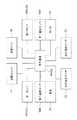
図5に示すように、第一ポンプ36A及び第二ポンプ36Bの駆動は、制御装置40によって制御される。たとえば、第一ポンプ36Aを駆動することで、第一流路34Aにおいて冷媒を循環させることが可能であり、第一ポンプ36Aの出力を調整することで、第一流路34Aを流れる冷媒の量を調整することも可能である。 As shown in FIG. 5, the driving of the first pump 36 </ b> A and the second pump 36 </ b> B is controlled by the
また、第二ポンプ36Bを駆動することで、第二流路34Bにおいて冷媒を循環させることが可能であり、第二ポンプの出力を調整することで、第二流路34Bを流れる冷媒の量を調整可能である。 Further, by driving the
さらに、第一ポンプ36Aと第二ポンプ36Bとをそれぞれ駆動することで、第一流路34A及び第二流路34Bの両方で冷媒を循環させたり、流路のそれぞれにおいて流れる冷媒の量を調整したりすることも可能である。 Further, by driving each of the
このように、本実施形態では、冷媒の実際の流路を、第一流路34A及び第二流路34Bのいずれか一方若しくは両方になるように切り替える切替部材32が、第一ポンプ36A、第二ポンプ36B及び制御装置40を有する構造である。 As described above, in the present embodiment, the switching
ラジエータ26には、送風ファン38が取り付けられている。図5に示すように、送風ファン38の駆動は制御装置40によって制御される。本実施形態において、車室14Rの空気をラジエータ26に送る送風部材56は、送風ファン38と、開口16Dとを有する構造である。 A
送風ファン38の駆動により、図2に矢印F2で示すように、車室14Rから開口16Dを通過させてラジエータ26に当たる空気の流れを生じさせることができる。特に、本実施形態では、縦壁部16Cに対しラジエータ26が車両後方側に配置され、さらに、送風ファン38が、ラジエータ26よりもさらに車両後方側に配置されている。ラジエータ26は、開口16Dを通過した空気が送風ファン38に向かう経路上に位置しているので、送風ファン38により生成された風を、ラジエータ26に対し効率的に当てることができる。 By driving the
図3に示すように、本実施形態では、電池24、ラジエータ26及びモータ18が、フレーム部材42に搭載され一体化されている。フレーム部材42は、本実施形態では、車両前後方向に延在し、車両幅方向では車両14の中心線に対し対称の構造である。そして、フレーム部材42を、車両骨格部材、たとえばフロントサイドメンバ、リヤサイドメンバ、クロスメンバ等に取り付けることで、電池24、ラジエータ26及びモータ18を車体に組み付けることができる。 As shown in FIG. 3, in the present embodiment, the
本実施形態では、送風ファン38がラジエータ26に取り付けられている。すなわち、送風ファン38も電池24やモータ18と一体化されている。ラジエータ26が搭載されたフレーム部材42を車両骨格部材に取り付けることで、送風ファン38も車体に組み付けることができる。 In the present embodiment, the
図1に示すように、車両14の前部にはダッシュパネル30が配置されている。ダッシュパネル30は、全体として車両幅方向に延在する部材であり、車両14の内部において、車室14Rと、この車室14Rよりも前方側に位置する前方スペース14Sとの間に位置している。 As shown in FIG. 1, a
前方スペース14Sには、空調ユニット44が配置されている。空調ユニット44は、車室14Rの内部あるいは外部から空気が導入される。そして、導入された空気の温度を調整して、車室14Rの内部に送出することができる。本実施形態では、空調ユニット44は、導入された空気を冷却する。そして、冷却された空気(調整済み空気)を、車室14R内に供給することが可能である。 An
ダッシュパネル30には、空調ユニット44から供給された空調済空気を、ダクト46を経由して吹き出す吹出口48が形成されている。吹出口48からは、空調ユニット44の空調済空気が車両後方に向けて吹き出される。すなわち、車室14Rの内部では、図1に矢印F1で示すように、空調済空気の流れが、車両後方に向かう成分を有する。特に、本実施形態において、空調ユニット44が冷却空気を生成した場合は、吹出口48から冷却風が車両後方に向けて吹き出される。 The
なお、吹出口48は、このようにダッシュパネル30に形成された構造に限定されない。たとえば、ダクトを経由して、センターコンソール、ドア、ピラーなどから、空調済空気を車両後方に向けて送り出す構造でもよい。要するに、吹出口48は車室14Rに形成され、調整済空気を車両後方に向けて吹き出す構造であればよい。 In addition, the
図5に示すように、モータ18には、第一温度センサ50Aが設けられている。第一温度センサ50Aは、モータ18の温度を検出し、温度データを制御装置40に送る。 As shown in FIG. 5, the
同様に、電池24には、第二温度センサ50Bが設けられている。第二温度センサ50Bは、電池24の温度を検出し、温度データを制御装置40に送る。 Similarly, the
制御装置40では、第一温度センサ50A及び第二温度センサ50Bから送られた温度データに基づいて、第一ポンプ36A、第二ポンプ36B及び送風ファン38の駆動を制御する。 The
さらに、車両14は、車内温度センサ52および車外温度センサ54を有する。車内温度センサ52は、車内温度、すなわち車室14R内の空気の温度を検出し、温度データを制御装置40に送る。車外温度センサ54は、車外温度、すなわち車両14の外部の空気の温度を検出し、温度データを制御装置40に送る。 Further, the
次に、本実施形態の作用を説明する。 Next, the operation of this embodiment will be described.
本実施形態の車両構造12を有する車両14では、第一ポンプ36Aの駆動により、図4に矢印C1で示すように、第一流路34Aにおいて冷媒をラジエータ26とモータ18との間で循環させることができる。この冷媒の循環により、モータ18の熱をラジエータ26に移動させ、モータ18を冷却することができる。 In the
また、この車両14では、第二ポンプ36Bの駆動により、図4に矢印C2で示すように、第二流路34Bにおいて冷媒をラジエータ26と電池24との間で循環させることができる。この冷媒の循環により、電池24の熱をラジエータ26に移動させ、電池24を冷却することができる。 In the
第一流路34Aによる冷媒の循環と、第二流路34Bによる冷媒の循環とは、いずれか一方を行うことも可能であるが、双方を同時に行うことも可能である。すなわち、モータ18と電池24とをそれぞれ個別に冷却できる。 Either one of the refrigerant circulation through the
しかも、本実施形態の車両構造12では、送風ファン38を有しており、送風ファン38の駆動により、車室14R内の空気をラジエータ26に当てることができる。車室14R内の空気、特に、空調ユニット44によって生成された冷却風をラジエータ26に当てることで、ラジエータ26からの放熱を促進できる。すなわち、ラジエータ26よって冷媒を冷却する効果が高くなるので、この冷媒の循環により冷却されるモータ18や電池24についても、効果的に冷却できる。 In addition, the
実際にモータ18や電池24を冷却する場合は、以下の冷却方法を採ることが可能である。たとえば、第一温度センサ50Aで検出したモータ18の温度が所定値、一例として第一閾値を超えている場合は、制御装置40は、第一ポンプ36Aを駆動し、モータ18を冷却する。 When the
同様に、第二温度センサ50Bで検出した電池24の温度が所定値、一例として第二閾値を超えている場合は、制御装置40は、第二ポンプ36Bを駆動し、電池24を冷却する。 Similarly, when the temperature of the
ここで、所定時間経過しても第一温度センサ50A又は第二温度センサ50Bでの検出温度が低下しない場合や、さらにモータ18又は電池24の冷却を促進する必要が生じる場合もある。 Here, there is a case where the temperature detected by the first temperature sensor 50 </ b> A or the second temperature sensor 50 </ b> B does not decrease even after a predetermined time has elapsed, or it is necessary to further promote cooling of the
この場合、制御装置40は、車内温度センサ52で検出した車内温度と、車外温度センサ54で検出した車外温度とを比較する。そして、車内温度が車外温度よりも低い場合は、制御装置40は送風ファン38を駆動する。これにより、外気よりも低温である車室14R内の空気を効果的に利用し、この低温の空気をラジエータ26に当てて、ラジエータ26による冷媒の冷却を促進できる。 In this case, the
これに対し、車内温度が車外温度よりも高い場合は、制御装置40は、空調ユニット44を駆動し、冷却風を生成する。この冷却風は、吹出口48から車室14R内に吹き出されるので、車室14R内では、車両後方へ向かう成分を有する。このように車室14R内で車両後方へ向かう成分を有する冷却風を生じさせた状態で、制御装置40が送風ファン38を駆動する。これにより、車室14R内の冷却風をラジエータ26に当て、ラジエータ26による冷媒の冷却を促進できる。 On the other hand, when the vehicle interior temperature is higher than the vehicle exterior temperature, the
このように、本実施形態の車両構造12では、車室14R内において、外気よりも温度が低い空気、特に、空調ユニット44で生成し吹出口48から吹き出された冷却風を有効に用いて、ラジエータ26による冷媒の冷却を促進できる。そして、このようにラジエータ26により冷媒の冷却を促進することで、モータ18や電池24を効果的に冷却できる。 As described above, in the
フロアパネル16は縦壁部16Cを有しており、車室14R内の空気がラジエータ26に向けた流れる開口16Dは、この縦壁部16Cに形成されている。車室14R内において、吹出口48から吹き出された冷却風は、車両後方へ向かう成分を有しているので、この冷却風を開口16Dよって効率的に取り込んで、ラジエータ26に当てることができる。上記したように、空調ユニット44により冷却風を生成した場合は、車両14の前方側から送られた冷却風で乗員を冷却し、その後に車両14の後方側へ流れた冷却風を効果的にラジエータ26に引き込む。 The
しかも、ラジエータ26は、縦壁部16Cの車両後方側に配置されており、送風ファン38は、ラジエータ26よりもさらに車両後方側に配置されている。ラジエータ26が、開口16Dを通過した空気が送風ファン38に向かう経路に位置しているので、送風ファン38により生成された風を、ラジエータ26に対し略正面から効率的に当てることができる。 Moreover, the
特に、ラジエータ26に当たる空気の流れ方向(矢印F2方向)で見て、ラジエータ26の上流側には他の部材が重ねて配置されていない。したがって、ラジエータ26に、車室14Rの冷却風を直接的に当てることができ、冷却風による冷媒の冷却効果を高く得られる。 In particular, when viewed in the flow direction of the air impinging on the radiator 26 (the direction of the arrow F2), no other member is placed on the upstream side of the
本実施形態の車両構造12では、電池24、ラジエータ26及びモータ18がフレーム部材42に搭載されて一体化されている。したがって、これらの電池、ラジエータ及びモータが別体である構造と比較して、各部材を車体に組み付ける作業が容易であり、車両14の生産性が高い。 In the
本実施形態の車両構造12では、ラジエータ26とモータ18の間で冷媒を循環させる第一流路34Aと、ラジエータ26と電池24の間で冷媒を循環させる第二流路34Bと、を有する。これら2つの流路を有さず、たとえば、第一流路34Aのみであっても、ラジエータ26とモータ18の間で冷媒を循環させることで、モータ18を冷却できる。同様に、第二流路34Bのみであっても、ラジエータ26と電池24との間で冷媒を循環させることで、電池24を冷却できる。第一流路34Aと第二流路34Bの両方を有する構造では、ラジエータ26と、モータ18と電池24の両方との間で冷媒を循環させて、モータ18及び電池24をそれぞれ冷却することが可能である。 The
しかも、このように冷媒の2つの流路を設けた構造であっても、実質的には、ラジエータ26を間において、モータ18と電池24とに接続される1つの流路(冷却回路)として構成できる。これにより、ラジエータ26とモータ18及び電池24との間で冷媒を循環させる構造の低コスト化、軽量化を図ることができる。 Moreover, even in the structure in which the two flow paths for the refrigerant are provided in this way, the flow is substantially as one flow path (cooling circuit) connected to the
第一流路34Aには第一ポンプ36Aが設けられている。第一ポンプ36Aを駆動することで、第一流路34Aにおいて冷媒の循環を確実に生じさせることができる。さらには、第一ポンプ36Aの出力を調整することで、第一流路34Aにおける冷媒の循環量を調整することも可能である。ここでいう冷媒の循環量とは、単位時間に循環する冷媒の量である。 A
特に、上記実施形態では、第一温度センサ50Aでモータ18の温度を検出しており、この検出温度に基づいて第一ポンプ36Aを駆動する。すなわち、第一流路34Aにおいて冷媒の循環が必要な場合に、確実に冷媒を循環させることができる。 In particular, in the above embodiment, the temperature of the
同様に、第二流路34Bには第二ポンプ36Bが設けられている。第二ポンプ36Bを駆動することで、第二流路34Bにおいて冷媒の循環を確実に生じさせることができる。さらには、第二ポンプ36Bの出力を調整することで、第一流路34Aにおける冷媒の循環量を調整することも可能である。 Similarly, a
特に、上記実施形態では、第二温度センサ50Bで電池24の温度を検出しており、この検出温度に基づいて第二ポンプ36Bを駆動する。すなわち、第二流路34Bにおいて冷媒の循環が必要な場合に、確実に冷媒を循環させることができる。 In particular, in the above embodiment, the temperature of the
たとえば、電池24への急速充電時には、電池24の温度は上昇するが、モータ18は駆動されないので温度が上昇しない場合がある。この場合には、第二ポンプ36Bは駆動して第二流路34Bで冷媒は循環させるが、第一ポンプ36Aは駆動させないことで、無駄な電力消費を抑制しつつ電池24を効果的に冷却できる。これに対し、車両14の過負荷走行時には、モータ18及び電池24の双方の温度が上昇する場合がある。この場合には、第一ポンプ36A及び第二ポンプ36Bの双方を駆動し、第一流路34Aでの冷媒循環と、第二流路34Bでの冷媒循環を生じさせれば、モータ18及び電池24を効果的に冷却できる。 For example, when the
なお、モータ18や電池24の温度上昇は、それぞれ第一温度センサ50A及び第二温度センサ50Bを用いることなく検出することも可能である。たとえば、モータ18の消費電力量からモータ18の温度を推定することが可能である。また、電池24において充電時の電流値から電池24の温度を推定することも可能である。 Note that the temperature rise of the
上記実施形態では、切替部材32として、第一ポンプ36A、第二ポンプ36B及び制御装置40とを有し、これら2台のポンプが制御装置40により制御される構造である。切替部材32としては、これに代わる構造も採りうる。たとえば、上記したように、第一流路34Aの一部と第二流路34Bの一部を共通化した構造では、流路の共通部分に1台のポンプを設け、流路の分岐部分に、切替弁を設ければよい。すなわち、制御装置により、ポンプと切替弁とを制御することで、実際に冷媒を流す流路を第一流路34Aと第二流路34Bのいずれか一方若しくは両方に切り替えることができる。 In the above embodiment, the switching
また、第一ポンプ36Aがない構造であっても、第一流路34Aにおいて冷媒を循環させることは可能である。たとえば、モータ18から受けた熱により気化してラジエータ26に移動し、ラジエータ26による放熱で液化してモータ18に戻る物性の冷媒を使用すればよい。 Even if the
同様に、第二ポンプ36Bがない構造であっても、第二流路34Bにおいて冷媒を循環させることは可能である。たとえば、モータ18から受けた熱により機会してラジエータ26に移動し、ラジエータ26による放熱で液化して電池24に戻る物性の冷媒を使用すればよい。 Similarly, even in a structure without the
上記実施形態の車両構造12では、フロアパネル16が、低位部16A、高位部16B及び縦壁部16Cを有する構造である。低位部16Aの下方に電池24を搭載し、高位部16Bの方にモータ18を搭載することで、フロアパネル16の下方のスペースを効果的に用いて、モータ18及び電池24を車両14に搭載できる。 In the
しかも、上記実施形態の車両構造12では、モータ18が後輪22を駆動する構造であり、モータ18は後輪22の近傍に配置される。そして、モータ18と、電池24の間のスペースを有効に利用して、ラジエータ26及び送風ファン38を配置できる。 Moreover, in the
上記実施形態の車両構造12において、車両14に搭載する電池としては、モータ18を駆動するための電力供給ができる電池であれば限定されないが、二次電池を用いれば、充電を行うことにより繰り返し使用できる。また、燃料の化学反応により電力を生じる燃料電池を用いることも可能である。 In the
12 車両構造
14 車両
14R 車室
16 フロアパネル
16A 低位部
16B 高位部
16C 縦壁部
16D 開口
18 モータ
24 電池
26 ラジエータ
28 冷却ユニット
30 ダッシュパネル
32 切替部材
34A 第一流路
34B 第二流路
36A 第一ポンプ
36B 第二ポンプ
38 送風ファン
40 制御装置
42 フレーム部材
44 空調ユニット
48 吹出口
56 送風部材12
Claims (7)
Translated fromJapanese前記モータへ電力を供給する電池と、
車両上下方向で相対的に低い位置にある低位部と、前記低位部よりも前記車両の後方で前記低位部より高い位置にある高位部と、前記低位部と前記高位部とに連続する縦壁部と、を備えるフロアパネルと、
前記フロアパネルの下側に配置され冷媒の循環により前記モータ及び前記電池の少なくとも一方から熱が移動するラジエータを備えた冷却ユニットと、
前記車両の車室内へ冷却空気を供給する空調ユニットと、
前記縦壁部に形成され前記車室内の空気が前記ラジエータに向けて通過可能な開口と、前記車室内の空気を、前記開口を通過させて前記ラジエータに送る送風ファンと、を備え、前記車室内の空気を前記ラジエータに送る送風部材と、
を有する車両構造。A motor that drives the wheels of the vehicle;
A battery for supplying power to the motor;
A low wall portion that is relatively low in the vehicle vertical direction, a high wall portion that is located behind the vehicle and higher than the low wall portion, and a vertical wall that is continuous with the low wall portion and the high wall portion. A floor panel comprising:
A cooling unit including a radiator disposed below thefloor panel and moving heat from at least one of the motor and the battery by circulation of a refrigerant;
An air conditioning unit for supplying cooling air to the vehicle interior of the vehicle;
An opening formed in the vertical wall portion through which air in the vehicle interior can pass toward the radiator, and a blower fan that sends the air in the vehicle interior to the radiator through the opening. A blowing member that sends indoor air to the radiator;
Vehicle structure having
前記モータと前記ラジエータの間で前記冷媒が循環する第一流路と、
前記電池と前記ラジエータの間で前記冷媒が循環する第二流路と、
を有する請求項1に記載の車両構造。The cooling unit is
A first flow path through which the refrigerant circulates between the motor and the radiator;
A second flow path through which the refrigerant circulates between the battery and the radiator;
The vehicle structure according to claim 1.
前記第一流路に設けられる第一ポンプと、
前記第二流路に設けられる第二ポンプと、
前記第一ポンプ及び前記第二ポンプを制御する制御装置と、
を有する請求項3に記載の車両構造。The switching device is
A first pump provided in the first flow path;
A second pump provided in the second flow path;
A control device for controlling the first pump and the second pump;
The vehicle structure according to claim 3.
前記モータが前記高位部の下方に配置され、
前記ラジエータ及び前記送風ファンが前記縦壁部の後方に配置されている請求項5に記載の車両構造。The battery is disposed below the lower portion;
The motor is disposed below the high-order part;
The vehicle structure according toclaim 5 , wherein the radiator and the blower fan are disposed behind the vertical wall portion.
前記電池、前記ラジエータ、及び前記モータがフレーム部材に搭載されて一体化されている請求項1〜請求項6のいずれか1項に記載の車両構造。The blower fan is attached to the radiator;
The vehicle structure according to any one ofclaims 1 to 6 , wherein the battery, the radiator, and the motor are mounted on and integrated with a frame member.
Priority Applications (4)
| Application Number | Priority Date | Filing Date | Title |
|---|---|---|---|
| JP2016150626AJP6465082B2 (en) | 2016-07-29 | 2016-07-29 | Vehicle structure |
| US15/650,477US10486526B2 (en) | 2016-07-29 | 2017-07-14 | Vehicle configuration |
| CN201710602766.0ACN107662483B (en) | 2016-07-29 | 2017-07-21 | vehicle construction |
| DE102017116766.8ADE102017116766B4 (en) | 2016-07-29 | 2017-07-25 | VEHICLE CONFIGURATION |
Applications Claiming Priority (1)
| Application Number | Priority Date | Filing Date | Title |
|---|---|---|---|
| JP2016150626AJP6465082B2 (en) | 2016-07-29 | 2016-07-29 | Vehicle structure |
Publications (2)
| Publication Number | Publication Date |
|---|---|
| JP2018016282A JP2018016282A (en) | 2018-02-01 |
| JP6465082B2true JP6465082B2 (en) | 2019-02-06 |
Family
ID=60951179
Family Applications (1)
| Application Number | Title | Priority Date | Filing Date |
|---|---|---|---|
| JP2016150626AExpired - Fee RelatedJP6465082B2 (en) | 2016-07-29 | 2016-07-29 | Vehicle structure |
Country Status (4)
| Country | Link |
|---|---|
| US (1) | US10486526B2 (en) |
| JP (1) | JP6465082B2 (en) |
| CN (1) | CN107662483B (en) |
| DE (1) | DE102017116766B4 (en) |
Families Citing this family (15)
| Publication number | Priority date | Publication date | Assignee | Title |
|---|---|---|---|---|
| JP6885308B2 (en)* | 2017-11-20 | 2021-06-09 | トヨタ自動車株式会社 | Vehicle temperature control system |
| JP6688825B2 (en)* | 2018-03-28 | 2020-04-28 | 本田技研工業株式会社 | vehicle |
| JP6752258B2 (en) | 2018-09-12 | 2020-09-09 | 本田技研工業株式会社 | vehicle |
| JP7190887B2 (en)* | 2018-12-03 | 2022-12-16 | 株式会社Subaru | cooling system |
| JP7191290B2 (en)* | 2018-12-26 | 2022-12-19 | マツダ株式会社 | Battery-equipped device |
| DE102019205431A1 (en) | 2019-04-15 | 2020-10-15 | Brose Fahrzeugteile SE & Co. Kommanditgesellschaft, Würzburg | Cooling device for a motor vehicle |
| JP7238812B2 (en) | 2020-01-22 | 2023-03-14 | トヨタ自動車株式会社 | Vehicle cooling structure |
| KR102829334B1 (en)* | 2020-02-13 | 2025-07-04 | 현대자동차주식회사 | Multi-path cooling system and cooling system for eco-friendly vehicle applying the same |
| CN115697746B (en)* | 2020-05-29 | 2025-08-01 | 日产自动车株式会社 | Discharge structure of battery cooling air |
| JP2022014683A (en)* | 2020-07-07 | 2022-01-20 | ヤマハ発動機株式会社 | vehicle |
| DE102021107409A1 (en)* | 2021-03-24 | 2022-09-29 | Weidemann GmbH | Mobile work machine, in particular wheel loader, with an electric drive motor |
| JP7545365B2 (en)* | 2021-05-27 | 2024-09-04 | トヨタ自動車株式会社 | Cooling Structure |
| CN113580884B (en)* | 2021-08-23 | 2023-09-19 | 山西省农业机械发展中心 | Engine cooling structure |
| CN119072412A (en)* | 2022-04-25 | 2024-12-03 | 株式会社电装 | Electric Vehicles |
| FR3155167B1 (en)* | 2023-11-09 | 2025-09-26 | Stellantis Auto Sas | MOTOR VEHICLE COMPRISING AN AIR VENT OPENING INTO A PASSENGER COMPARTMENT |
Family Cites Families (46)
| Publication number | Priority date | Publication date | Assignee | Title |
|---|---|---|---|---|
| JP3125198B2 (en)* | 1991-12-04 | 2001-01-15 | 本田技研工業株式会社 | Battery temperature control device for electric vehicle |
| US5392873A (en)* | 1992-01-22 | 1995-02-28 | Honda Giken Kogyo Kabushiki Kaisha | Structure for securing batteries used in an electric vehicle |
| JP2000315513A (en)* | 1999-05-06 | 2000-11-14 | Nissan Motor Co Ltd | Radiator system for fuel cell vehicle |
| US6394210B2 (en)* | 1999-06-07 | 2002-05-28 | Mitsubishi Heavy Industries, Ltd. | Temperature controller for vehicular battery |
| US6357541B1 (en)* | 1999-06-07 | 2002-03-19 | Mitsubishi Heavy Industries, Ltd. | Circulation apparatus for coolant in vehicle |
| ES2320924T3 (en)* | 2002-06-10 | 2009-05-29 | Toyota Jidosha Kabushiki Kaisha | FUEL BATTERY VEHICLE. |
| US6902020B2 (en)* | 2002-07-29 | 2005-06-07 | Daimlerchrysler Corporation | Interior vehicle battery system and method |
| JP4109953B2 (en) | 2002-10-03 | 2008-07-02 | トヨタ自動車株式会社 | Vehicle with fuel cell |
| JP4519516B2 (en)* | 2003-07-15 | 2010-08-04 | 本田技研工業株式会社 | Heating / cooling device for vehicle electrical unit and hybrid vehicle |
| JP4707346B2 (en)* | 2004-08-16 | 2011-06-22 | 三洋電機株式会社 | Power supply for vehicle |
| JP2006218966A (en)* | 2005-02-09 | 2006-08-24 | Toyota Motor Corp | Vehicle with fuel cell |
| JP4644034B2 (en)* | 2005-05-24 | 2011-03-02 | 本田技研工業株式会社 | Cooling device for fuel cell vehicle |
| JP4274165B2 (en)* | 2005-10-06 | 2009-06-03 | トヨタ自動車株式会社 | Cooling device for on-vehicle equipment |
| JP2008055990A (en)* | 2006-08-30 | 2008-03-13 | Calsonic Kansei Corp | Vehicular battery cooling system |
| EP1961601B1 (en)* | 2007-02-23 | 2011-09-21 | Halla Climate Control Corporation | Battery cooling device for vehicles and control method thereof |
| JP4957492B2 (en)* | 2007-09-28 | 2012-06-20 | 三菱自動車工業株式会社 | Electric vehicle battery unit cooling duct structure |
| US9960461B2 (en)* | 2008-10-15 | 2018-05-01 | General Electric Company | System and method for temperature control of multi-battery systems |
| JP4478900B1 (en)* | 2008-12-03 | 2010-06-09 | 本田技研工業株式会社 | Capacitor heating device |
| JP2010274675A (en)* | 2009-05-26 | 2010-12-09 | Toyota Motor Corp | Fuel cell system |
| JP5430276B2 (en)* | 2009-08-03 | 2014-02-26 | 本田技研工業株式会社 | Cooling structure for vehicle battery |
| FR2948898B1 (en)* | 2009-08-07 | 2012-04-06 | Renault Sa | GLOBAL THERMAL CONTROL SYSTEM FOR MOTOR VEHICLE WITH ELECTRIC PROPULSION. |
| DE102009043316A1 (en)* | 2009-09-28 | 2011-03-31 | Valeo Klimasysteme Gmbh | Method for controlling the interior temperature of an electrically operated vehicle and air conditioning system |
| JP5331722B2 (en)* | 2010-02-05 | 2013-10-30 | 株式会社日立製作所 | Vehicle electric drive system |
| US9583800B2 (en) | 2010-03-08 | 2017-02-28 | Lg Electronics Inc. | Vehicle and method for controlling same |
| US8662226B2 (en)* | 2010-06-08 | 2014-03-04 | Ford Global Technologies, Llc | Apparatus for heating a vehicle cabin |
| DE102010030892B4 (en)* | 2010-07-02 | 2012-01-26 | Visteon Global Technologies, Inc. | Air conditioning system for vehicles with battery cooling |
| EP2409864B1 (en)* | 2010-07-19 | 2013-03-27 | C.R.F. Società Consortile per Azioni | Automotive air-conditioning system |
| CN102452297B (en)* | 2010-10-29 | 2014-07-09 | 杭州三花研究院有限公司 | Electric automobile and heat management system thereof |
| KR101180954B1 (en)* | 2010-12-03 | 2012-09-07 | 기아자동차주식회사 | High voltage battery cooling system of vehicle |
| CN103781667B (en)* | 2011-10-24 | 2016-05-18 | 本田技研工业株式会社 | The distribution protective cover structure of electric vehicle |
| JP5503087B2 (en)* | 2011-11-14 | 2014-05-28 | 本田技研工業株式会社 | Electric vehicle battery pack and battery pack mounting structure |
| JP5788774B2 (en)* | 2011-11-21 | 2015-10-07 | 日立オートモティブシステムズ株式会社 | Cooling system |
| JP2013193632A (en) | 2012-03-22 | 2013-09-30 | Mitsubishi Heavy Ind Ltd | Cooling system |
| JP6060797B2 (en)* | 2012-05-24 | 2017-01-18 | 株式会社デンソー | Thermal management system for vehicles |
| JP5983054B2 (en)* | 2012-06-04 | 2016-08-31 | スズキ株式会社 | Hybrid vehicle battery pack cooling structure |
| US10046617B2 (en)* | 2013-02-01 | 2018-08-14 | Ford Global Technologies, Llc | Electric vehicle multi-loop thermal management system |
| JP5962556B2 (en)* | 2013-03-19 | 2016-08-03 | 株式会社デンソー | Thermal management system for vehicles |
| CN104121724B (en)* | 2013-04-27 | 2018-10-26 | 浙江三花汽车零部件有限公司 | A kind of air-conditioning system and a kind of heat exchanger |
| JP6187163B2 (en)* | 2013-10-31 | 2017-08-30 | トヨタ自動車株式会社 | Battery cooling structure |
| JP6297922B2 (en)* | 2014-05-23 | 2018-03-20 | 株式会社デンソー | Battery pack |
| US9550406B2 (en)* | 2015-03-16 | 2017-01-24 | Thunder Power Hong Kong Ltd. | Thermal dissipation system of an electric vehicle |
| DE112016003548T5 (en)* | 2015-08-03 | 2018-04-12 | Denso Corporation | Refrigeration cycle device |
| JP2017165222A (en)* | 2016-03-15 | 2017-09-21 | 本田技研工業株式会社 | Vehicle, battery unit, and battery mounting method for vehicle |
| JP6442450B2 (en)* | 2016-08-24 | 2018-12-19 | 本田技研工業株式会社 | vehicle |
| JP6483654B2 (en)* | 2016-12-14 | 2019-03-13 | 本田技研工業株式会社 | Vehicle cooling device |
| FR3063936A1 (en)* | 2017-03-16 | 2018-09-21 | Valeo Systemes Thermiques | METHOD AND INSTALLATION FOR THE THERMAL REGULATION OF AN ELECTRICAL DRIVE CHAIN OF A VEHICLE |
- 2016
- 2016-07-29JPJP2016150626Apatent/JP6465082B2/ennot_activeExpired - Fee Related
- 2017
- 2017-07-14USUS15/650,477patent/US10486526B2/enactiveActive
- 2017-07-21CNCN201710602766.0Apatent/CN107662483B/ennot_activeExpired - Fee Related
- 2017-07-25DEDE102017116766.8Apatent/DE102017116766B4/ennot_activeExpired - Fee Related
Also Published As
| Publication number | Publication date |
|---|---|
| DE102017116766B4 (en) | 2021-01-28 |
| US20180029463A1 (en) | 2018-02-01 |
| DE102017116766A1 (en) | 2018-02-01 |
| US10486526B2 (en) | 2019-11-26 |
| CN107662483B (en) | 2020-06-19 |
| JP2018016282A (en) | 2018-02-01 |
| CN107662483A (en) | 2018-02-06 |
Similar Documents
| Publication | Publication Date | Title |
|---|---|---|
| JP6465082B2 (en) | Vehicle structure | |
| CN102803006B (en) | automobile and control method thereof | |
| JP6245789B2 (en) | Electric vehicle battery pack temperature control structure | |
| US11511651B2 (en) | Vehicular air conditioner | |
| WO2011145380A1 (en) | Vehicle battery cooling system | |
| US20230100068A1 (en) | Vehicle-body structure with air conditioner | |
| US20150101354A1 (en) | Air conditioning system and method for high-voltage battery of vehicle | |
| JP5630574B2 (en) | Heat exchange structure for vehicles | |
| JP2020100189A (en) | Temperature adjusting control system of electric vehicle | |
| WO2013125353A1 (en) | Battery pack temperature control structure for electric vehicles | |
| US7975637B1 (en) | Temperature control system for a hybrid vehicle | |
| KR101595170B1 (en) | Supplemental heating and cooling sources for a heating, ventilation and air conditioning system | |
| CN103921649A (en) | Return Air Ducts For Vehicles | |
| CN103219560B (en) | Drive battery arrangement and motor vehicle having a drive battery arrangement | |
| JP2018043727A (en) | Air conditioning device for vehicle | |
| WO2016042709A1 (en) | Cooling apparatus | |
| JP6507568B2 (en) | Automotive equipment cooling structure | |
| JP7137497B2 (en) | Cooling device for electric four-wheel drive vehicle | |
| CN107953740B (en) | air conditioning unit | |
| JP5754385B2 (en) | Battery cooling system for vehicles | |
| JP6097975B2 (en) | Vehicle cooling device | |
| JP6065817B2 (en) | Vehicle interior temperature detection module and vehicle air conditioner equipped with the same | |
| KR20150085372A (en) | Independence type rear air conditioner of vehicles | |
| JP2018075945A (en) | Battery cooling mechanism and mobile vehicle | |
| JP7404889B2 (en) | vehicle |
Legal Events
| Date | Code | Title | Description |
|---|---|---|---|
| A977 | Report on retrieval | Free format text:JAPANESE INTERMEDIATE CODE: A971007 Effective date:20180426 | |
| A131 | Notification of reasons for refusal | Free format text:JAPANESE INTERMEDIATE CODE: A131 Effective date:20180522 | |
| A521 | Request for written amendment filed | Free format text:JAPANESE INTERMEDIATE CODE: A523 Effective date:20180702 | |
| TRDD | Decision of grant or rejection written | ||
| A01 | Written decision to grant a patent or to grant a registration (utility model) | Free format text:JAPANESE INTERMEDIATE CODE: A01 Effective date:20181211 | |
| A61 | First payment of annual fees (during grant procedure) | Free format text:JAPANESE INTERMEDIATE CODE: A61 Effective date:20181224 | |
| R151 | Written notification of patent or utility model registration | Ref document number:6465082 Country of ref document:JP Free format text:JAPANESE INTERMEDIATE CODE: R151 | |
| LAPS | Cancellation because of no payment of annual fees |