JP6464517B2 - Control device and lighting device - Google Patents
Control device and lighting deviceDownload PDFInfo
- Publication number
- JP6464517B2 JP6464517B2JP2018202496AJP2018202496AJP6464517B2JP 6464517 B2JP6464517 B2JP 6464517B2JP 2018202496 AJP2018202496 AJP 2018202496AJP 2018202496 AJP2018202496 AJP 2018202496AJP 6464517 B2JP6464517 B2JP 6464517B2
- Authority
- JP
- Japan
- Prior art keywords
- light source
- led light
- control device
- power
- sensor unit
- Prior art date
- Legal status (The legal status is an assumption and is not a legal conclusion. Google has not performed a legal analysis and makes no representation as to the accuracy of the status listed.)
- Active
Links
Images


Landscapes
- Non-Portable Lighting Devices Or Systems Thereof (AREA)
- Circuit Arrangement For Electric Light Sources In General (AREA)
- Arrangement Of Elements, Cooling, Sealing, Or The Like Of Lighting Devices (AREA)
Description
Translated fromJapanese本発明は、発光ダイオード(LED:Light Emitting Diode)を用いた照明用光源(照明器具)の制御装置に関する。 The present invention relates to a control device for a light source (lighting fixture) for illumination using a light emitting diode (LED).
LEDは、高効率及び長寿命であることから、従来から知られる蛍光灯や白熱電球等の各種ランプにおける新しい光源として期待されており、LEDランプの研究開発が進められている。 The LED is expected to be a new light source in various lamps such as fluorescent lamps and incandescent lamps that are conventionally known because of its high efficiency and long life, and research and development of LED lamps are underway.
LEDランプとしては、直管形蛍光灯に代替する直管LEDランプなどが知られている(例えば、特許文献1参照)。 Known LED lamps include straight tube LED lamps that replace straight tube fluorescent lamps (see, for example, Patent Document 1).
上記のようなLEDランプの中には、蛍光灯用の照明器具をそのまま利用し、当該照明器具に蛍光灯に代えて取り付けられることで点灯及び消灯が可能なLEDランプがある。しかしながら、このようなLEDランプを制御するために蛍光灯用の照明器具にリモコン機能などの新たな機能を追加したい場合には、工事等が必要であることが一般的である。 Among the LED lamps as described above, there is an LED lamp that can be turned on and off by using a lighting fixture for a fluorescent lamp as it is and being attached to the lighting fixture in place of the fluorescent lamp. However, when it is desired to add a new function such as a remote control function to a fluorescent lamp luminaire in order to control such an LED lamp, construction or the like is generally required.
そこで、本発明は、蛍光灯用の照明器具に容易に機能を追加することができる制御装置等を提供する。 Therefore, the present invention provides a control device or the like that can easily add a function to a lighting fixture for a fluorescent lamp.
本発明の一態様に係る制御装置は、グローソケットを有する照明器具に用いられる制御装置であって、前記グローソケットに取り付け可能な構造の取り付け部と、対象を検出するセンサ部と、前記取り付け部を介して前記グローソケットから得られる電力を用いて、前記照明器具に取り付けられたLED光源に流れる電流を前記センサ部の検出に応じて制御する制御部とを備える。 A control device according to one aspect of the present invention is a control device used in a lighting fixture having a glow socket, and has a structure that can be attached to the glow socket, a sensor unit that detects an object, and the attachment unit. And a control unit that controls the current flowing through the LED light source attached to the lighting fixture according to the detection of the sensor unit using the electric power obtained from the glow socket.
本発明の制御装置によれば、蛍光灯用の照明器具に容易に機能を追加することができる。 According to the control device of the present invention, it is possible to easily add a function to a fluorescent lamp.
以下、実施の形態について、図面を参照しながら具体的に説明する。なお、以下で説明する実施の形態は、いずれも包括的または具体的な例を示すものである。以下の実施の形態で示される数値、形状、材料、構成要素、構成要素の配置位置及び接続形態、ステップ、ステップの順序などは、一例であり、本発明を限定する主旨ではない。また、以下の実施の形態における構成要素のうち、最上位概念を示す独立請求項に記載されていない構成要素については、任意の構成要素として説明される。また、各図は、模式図であり、必ずしも厳密に図示されたものではない。 Hereinafter, embodiments will be specifically described with reference to the drawings. It should be noted that each of the embodiments described below shows a comprehensive or specific example. The numerical values, shapes, materials, constituent elements, arrangement positions and connecting forms of the constituent elements, steps, order of steps, and the like shown in the following embodiments are merely examples, and are not intended to limit the present invention. In addition, among the constituent elements in the following embodiments, constituent elements that are not described in the independent claims indicating the highest concept are described as optional constituent elements. Each figure is a mimetic diagram and is not necessarily illustrated strictly.
(実施の形態1)
[全体構成]
以下、実施の形態1に係る制御装置及びこれを用いた照明装置について説明する。図1は、実施の形態1に係る照明装置の外観図である。図2は、照明装置のうちの制御装置の取り付け部分の拡大図である。(Embodiment 1)
[overall structure]
Hereinafter, the control device according to the first embodiment and the lighting device using the same will be described. FIG. 1 is an external view of a lighting device according to Embodiment 1. FIG. FIG. 2 is an enlarged view of a mounting portion of the control device in the lighting device.
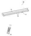
図1に示されるように、照明装置20は、制御装置10と、照明器具25と、直管LEDランプ30とを備える。また、図1には、リモートコントローラ40も図示されている。 As shown in FIG. 1, the
照明器具25は、従来の蛍光灯用の照明器具であって、いわゆるグロースタータ式の照明器具である。図2に示されるように、照明器具25は、照明器具25に取り付けられる光源への給電経路上にグローソケット26を有する。 The
制御装置10は、グローソケット26を有する照明器具に光源としてLED光源を取り付けた場合に用いられる制御装置である。制御装置10は、取り付け部11と、筐体12と、センサ部13とを備える。 The
取り付け部11は、グローソケット26に取り付け可能な構造であり、実施の形態1では、ねじ込み式のE17口金の形状に形成された金属製の端子である。 The attachment portion 11 has a structure that can be attached to the
取り付け部11は、より詳細には、第1端子11aと、第2端子11bとを有する。取り付け部11がグローソケット26に取り付けられる(ねじ込まれる)と、第1端子11aはグローソケット26内の第1電極(図2で図示せず)に電気的に接続され、第2端子11bは、グローソケット26内の第2電極26bに電気的に接続される。なお、取り付け部11は、一般的なグローソケットに取り付け可能な構造であればよく、例えば、P21口金の形状であってもよい。 In more detail, the attachment part 11 has the
筐体12は、内部に制御装置10の回路を構成する回路部品を収容した略円筒状の筐体である。筐体12の一端には、上述の取り付け部11が設けられ、取り付け部11と筐体12の内部の回路部品とは電気的に接続されている。筐体12は、例えば、樹脂によって形成され、筐体12の他端には、センサ部13が設けられる。 The
センサ部13は、対象を検出するセンサである。実施の形態1では、センサ部13は、リモートコントローラ40から送信される赤外線を対象として検出するリモートコントローラ40の受光部である。 The
リモートコントローラ40は、ユーザの指示を受け付ける、照明装置20のユーザインターフェースである。ユーザは、例えば、リモートコントローラ40に設けられたボタンを押下することにより、照明装置20の点灯及び消灯する。 The
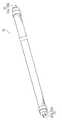
次に、直管LEDランプ30について、図3をさらに用いて説明する。図3は、直管LEDランプ30の外観図である。 Next, the straight
直管LEDランプ30は、直管形のLED光源の一例であって、照明器具25に取り付けられる。図3に示されるように、直管LEDランプ30の一端には、直管LEDランプ30を発光させるための交流電力が印加される口金ピン31a及び口金ピン31bからなる第1口金31が設けられる。また、直管LEDランプ30の他端には、直管LEDランプ30の内部で短絡された口金ピン32a及び口金ピン32bからなる第2口金32が設けられる。直管LEDランプ30では、片側給電方式が採用されている。 The straight
なお、口金ピン31aは、第1口金ピンの一例であり、口金ピン31bは、第2口金ピンの一例である。口金ピン32aは、第3口金ピンの一例であり、口金ピン32bは、第4口金ピンの一例である。第1口金31及び第2口金32は、いわゆるG13口金であるが、口金の形状は特に限定されるものではない。 The
[回路構成]
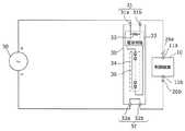
ここで、直管LEDランプ30の内部構成を含む、照明装置20の回路構成について説明する。図4は、照明装置20の回路構成を示す図である。[Circuit configuration]
Here, the circuit configuration of the
図4に示されるように、直管LEDランプ30は、上述の第1口金31及び第2口金32に加えて、電源回路33と、発光モジュール34とを備える。また、直管LEDランプ30は、交流電源50(商用系統、電力系統)から供給される電力により発光する。なお、図4では図示されないが、交流電源50の正極と口金ピン31aとの間、または、交流電源50の負極と口金ピン32aとの間に安定器が設けられる場合もある。 As shown in FIG. 4, the straight
電源回路33は、口金ピン31a及び口金ピン31bの間に供給される交流電力を直流電力に変換して出力する回路である。電源回路33には、具体的には、AC−DCコンバータ等が含まれる。なお、口金ピン31a及び31bの間には内部抵抗35がある。内部抵抗35は、概念的に図示されたものであり、必ずしも図示されたように抵抗素子が配置されることを意味するわけではない。 The
発光モジュール34は、発光素子としてLED36を有する発光モジュールであって、白色等の所定の色(波長)の光を放出する。発光モジュール34は、例えば、基板上に直接実装された青色光を発するLED36が黄色蛍光体を含む透光性樹脂で封止されたCOB(Chip On Board)型のLEDモジュールである。なお、発光モジュール34は、SMD(Surface Mount Device)型のLED素子を用いたSMD型の発光モジュールであってもよい。 The
直管LEDランプ30が照明器具25に取り付けられると、直管LEDランプ30の口金ピン31aは、照明器具25内の配線によって交流電源50の正極に電気的に接続される。口金ピン31bは、照明器具25内の配線によってグローソケット26の第1電極26aに電気的に接続される。 When the straight
同様に、直管LEDランプ30が照明器具25に取り付けられると、直管LEDランプ30の口金ピン32aは、照明器具25内の配線によって交流電源50の負極に電気的に接続される。口金ピン32bは、照明器具25内の配線によってグローソケット26の第2電極26bに電気的に接続される。ここで、上述のように口金ピン32aと口金ピン32bとは、直管LEDランプ30の内部で短絡されている。 Similarly, when the straight
従来、蛍光灯を照明器具25に取り付けて使用する場合、グローソケット26には、グロー球(グロー管、点灯管)が取り付けられていた。 Conventionally, when a fluorescent lamp is attached to the
また、蛍光灯に代えて直管LEDランプ30を照明器具25に取り付けて使用する場合、グローソケット26には、グローソケット26の第1電極26a及び第2電極26bを短絡するためのダミーグローが取り付けられていた。つまり、図4の制御装置10が配置された部分が短絡されていた。これにより、直管LEDランプ30の口金ピン31bが交流電源50(電力系統)の負極に電気的に接続されるため、電源回路33に交流電源50からの交流電力が供給され、直管LEDランプ30が点灯する。 Further, when the straight
ここで、実施の形態1に係る照明装置20においては、上記のグロー球またはダミーグローに代えて制御装置10が取り付けられ、制御装置10がリモートコントローラ40の受光部として機能するとともに、直管LEDランプ30に流れる電流を制御する。 Here, in the
つまり、照明装置20は、既存の蛍光灯用の照明器具25において蛍光灯に代えて直管LEDランプ30を取り付け、かつ、ダミーグローに代えて制御装置10を取り付けることによって実現される。言い換えれば、照明装置20は、蛍光灯用の照明器具25に対する簡単な部品の置き換えによって、工事等を行うことなく実現できる。制御装置10によれば、一般ユーザであっても容易にリモートコントロール機能などの機能を照明器具25に追加することができる。 That is, the illuminating
[制御装置の構成]
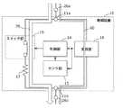
以下、このような制御装置10の詳細構成について説明する。図5は、制御装置10の詳細構成を示す図である。[Configuration of control device]
Hereinafter, a detailed configuration of the
図5に示されるように、制御装置10は、上述の取り付け部11(第1端子11a及び第2端子11b)並びにセンサ部13に加えて、制御部14と、スイッチ部15と、変換部16とを備える。 As shown in FIG. 5, the
変換部16は、取り付け部11(第1端子11a及び第2端子11b)を介してグローソケット26(第1電極26a及び第2電極26b)から得られる交流電力を直流電力に変換する。そして、変換部16は、直流電力をセンサ部13及び制御部14に出力(供給)する。変換部16は、具体的には、AC−DCコンバータを含む電源回路であるが、交流電力を直流電力に変換できるのであれば、どのような構成であってもよい。 The
スイッチ部15は、第1端子11aと第2端子11bとの間の導通及び非導通を切り替えるスイッチ機能を有する素子である。スイッチ部15は、取り付け部11の第1端子11aと第2端子11bとの間に設けられ、制御部14によって導通及び非導通が制御される。スイッチ部15は、具体的には、トランジスタや、リレー素子により構成される。なお、図5では、スイッチ部15と直列に抵抗17が設けられている。なお、抵抗17は、スイッチ部15に含まれてもよい。 The
制御部14は、取り付け部11を介してグローソケット26から得られる電力を用いて、照明器具25に取り付けられた直管LEDランプ30に流れる電流をセンサ部13の検出に応じて制御する。制御部14は、より具体的には、変換部16が出力する直流電力を用いて、センサ部13が出力する制御信号に基づいてスイッチ部15の導通及び非導通を制御する。制御部14は、具体的には、マイクロコンピュータであるが、プロセッサまたは専用回路で実現されてもよい。 The
以下、制御部14の制御について、詳細に説明する。図6は、スイッチ部15が非導通状態である場合の電流の流れを示す模式図である。図7は、スイッチ部15が導通状態である場合の電流の流れを示す模式図である。なお、以下の説明では、図4も適宜参照される。 Hereinafter, the control of the
図6に示されるように、スイッチ部15が非導通状態である場合、変換部16には、電源回路33の内部抵抗35を介して交流電源50から交流電力が供給され、変換部16及び電源回路33には、図6の矢印60のように微弱な電流が流れる。 As shown in FIG. 6, when the
この状態においては、電流が微弱であるため、発光モジュール34は点灯しないが、変換部16は動作する。すなわち、変換部16から出力される電力により、センサ部13及び制御部14は動作する。 In this state, since the current is weak, the
なお、この状態は、例えば、ユーザがリモートコントローラ40の消灯ボタンを押した後の状態に相当する。このとき、センサ部13は、消灯ボタンの押下に応じてリモートコントローラ40から送信される赤外線を検出し、検出した赤外線に応じた制御信号を制御部14に出力する。制御部14は、この制御信号に基づいてスイッチ部15を非導通状態とする。 This state corresponds to, for example, a state after the user presses the extinguishing button of the
これに対し、図7に示されるように、スイッチ部15が導通状態である場合、図7の矢印70に示されるように、スイッチ部15及び抵抗17を介して電流が流れ、図4に図示される電源回路33には、抵抗17を介して交流電源50から交流電力が供給される。 On the other hand, as shown in FIG. 7, when the
この状態においては、電源回路33に供給される電流は図6の状態よりも大きいため、発光モジュール34は点灯し、かつ、変換部16は動作する。なお、この状態は、例えば、ユーザがリモートコントローラの点灯ボタンを押した後の状態に相当する。このとき、センサ部13は、点灯ボタンの押下に応じてリモートコントローラ40から送信される赤外線を検出し、検出した赤外線に応じた制御信号を制御部14に出力する。制御部14は、この制御信号に基づいてスイッチ部15を導通状態とする。 In this state, since the current supplied to the
[効果等]
以上説明したように、制御装置10は、グローソケット26に取り付け可能な構造の取り付け部11と、センサ部13と、グローソケット26から得られる電力を用いて、直管LEDランプ30に流れる電流をセンサ部13の検出に応じて制御する制御部14とを備える。[Effects]
As described above, the
これにより、蛍光灯用の照明器具25のグローソケット26を利用して、一般ユーザであっても簡単に照明器具25にセンサ機能を付加することができる。 Thereby, even if it is a general user, a sensor function can be easily added to the
なお、上記実施の形態では、センサ部13は、リモートコントローラ40が送信する赤外線を検出したが、センサ部13は、これ以外の対象を検出してもよい。例えば、センサ部13として、人(人体から発せられる赤外線)を検出する人感センサが用いられてもよい。この場合、照明装置20は、人を検出してから一定期間点灯し、その後消灯する人感センサ機能付の照明装置として動作する。なお、この場合、制御装置10は、上記一定期間をカウントするタイマ部を備える。 In the above embodiment, the
また、例えば、センサ部13は、センサ部13の周辺の照度、音、振動、及び温度などを検出してもよい。この場合、センサ部13には、既存の照度センサ、音センサ、振動センサ、温度センサなどが適用できる。 For example, the
例えば、センサ部13が照度センサである場合、制御部14は、センサ部13が検出した照度が所定の照度以下である(または所定の照度よりも大きい)場合に、直管LEDランプ30を点灯させる、といった制御を行う。センサ部13が音センサ、振動センサ、温度センサ、及び振動センサである場合についても同様である。 For example, when the
(その他の実施の形態)
以上、実施の形態に係る制御装置及び照明装置について説明したが、本発明は、上記実施の形態に限定されるものではない。(Other embodiments)
Although the control device and the lighting device according to the embodiment have been described above, the present invention is not limited to the above embodiment.
上記実施の形態では、制御部14及びセンサ部13は、取り付け部11を介してグローソケット26から得られる電力を用いて動作したが、制御部14及びセンサ部13は、例えば、電池(または蓄電池)から供給される電力を用いて動作してもよい。この場合、制御装置10の筐体12には小型のボタン電池等が内蔵される。また、この場合、抵抗17は不要となる。 In the said embodiment, although the
また、上記実施の形態では、制御部14は、直管LEDランプ30の点灯及び消灯を制御したが、制御部14は、直管LEDランプ30に流れる電流を制御すればよい。例えば、制御部14は、直管LEDランプ30の調光を制御してもよい。例えば、上記図5において、抵抗17に代えて、または、抵抗17に加えて、デジタルポテンショメータ等により構成される可変抵抗が設けられ、制御部14は可変抵抗の抵抗値を制御する。これにより、電源回路33に供給される電流量を制御でき、直管LEDランプ30の調光が可能となる。 Moreover, in the said embodiment, although the
例えば、センサ部13として照度センサが用いられれば、センサ部13が検出した照度が低いほど、直管LEDランプ30を明るく発光させる(または暗く発光させる)といった制御部14の制御が可能となる。 For example, if an illuminance sensor is used as the
また、上記実施の形態では、LED光源の一例として、直管LEDランプ30が用いられたが、本発明は、他の光源を用いた照明装置としても実現可能である。例えば、光源として、図8に示されるような円環状のLEDランプ130が用いられてもよい。 Moreover, in the said embodiment, although the straight tube |
また、LED光源に代えて、例えば、半導体レーザ等の半導体発光素子、有機EL(Electro Luminescence)または無機EL等の固体発光素子を有する光源が用いられてもよい。本発明は、グロースタータ式の照明器具に取り付け可能な構造の光源であって、グロー球なしで点灯する光源を備える照明装置に適用できる。 Instead of the LED light source, for example, a light source having a semiconductor light emitting element such as a semiconductor laser, a solid light emitting element such as an organic EL (Electro Luminescence), or an inorganic EL may be used. The present invention can be applied to a lighting device having a light source having a structure that can be attached to a glow starter type lighting fixture and having a light source that is lit without a glow sphere.
また、上記実施の形態において、各構成要素(例えば、制御部14)は、専用のハードウェアで構成されるか、各構成要素に適したソフトウェアプログラムを実行することによって実現されてもよい。各構成要素は、CPUまたはプロセッサなどのプログラム実行部が、ハードディスクまたは半導体メモリなどの記録媒体に記録されたソフトウェアプログラムを読み出して実行することによって実現されてもよい。 In the above-described embodiment, each component (for example, the control unit 14) may be configured by dedicated hardware or may be realized by executing a software program suitable for each component. Each component may be realized by a program execution unit such as a CPU or a processor reading and executing a software program recorded on a recording medium such as a hard disk or a semiconductor memory.
また、各構成要素は、回路(または集積回路)でもよい。これらの回路は、全体として1つの回路を構成してもよいし、それぞれ別々の回路でもよい。また、これらの回路は、それぞれ、汎用的な回路でもよいし、専用の回路でもよい。 Each component may be a circuit (or an integrated circuit). These circuits may constitute one circuit as a whole, or may be separate circuits. Each of these circuits may be a general-purpose circuit or a dedicated circuit.
その他、各実施の形態に対して当業者が思いつく各種変形を施して得られる形態、または、本発明の趣旨を逸脱しない範囲で各実施の形態における構成要素及び機能を任意に組み合わせることで実現される形態も本発明に含まれる。 In addition, it is realized by variously conceiving various modifications conceived by those skilled in the art for each embodiment, or by arbitrarily combining the components and functions in each embodiment without departing from the spirit of the present invention. This form is also included in the present invention.
10 制御装置
11 取り付け部
11a 第1端子
11b 第2端子
13 センサ部
14 制御部
15 スイッチ部
16 変換部
20 照明装置
25 照明器具
26 グローソケット
26a 第1電極
26b 第2電極
30 直管LEDランプ(LED光源)
130 円環状のLEDランプ(LED光源)
31 第1口金
31a 口金ピン(第1口金ピン)
31b 口金ピン(第2口金ピン)
32 第2口金
32a 口金ピン(第3口金ピン)
32b 口金ピン(第4口金ピン)
40 リモートコントローラDESCRIPTION OF
130 Circular LED lamp (LED light source)
31
31b Cap pin (second cap pin)
32
32b cap pin (fourth cap pin)
40 Remote controller
Claims (7)
Translated fromJapanese前記グローソケットに取り付け可能な構造の取り付け部と、
対象を検出するセンサ部と、
前記取り付け部を介して前記グローソケットから得られる交流電力を直流電力に変換して出力する変換部と、
前記変換部が出力する直流電力を用いて、前記照明器具に取り付けられたLED光源に流れる電流を前記センサ部の検出に応じて制御する制御部とを備え、
前記制御装置には、
前記LED光源が発光しているときに前記交流電力が供給される、前記変換部を含まない電力供給経路と、
前記LED光源が発光しているとき、及び、前記LED光源が発光していないときのいずれも前記交流電力が供給される、前記変換部を含む電力供給経路とが設けられる
制御装置。A control device used in a lighting fixture having a glow socket,
An attachment portion having a structure attachable to the glow socket;
A sensor unit for detecting an object;
A converter that converts alternating current power obtained from the glow socket through the attachment portion into direct current power and outputs the direct current power; and
A controller for controlling the current flowing through the LED light source attached to the lighting fixture according to the detection of the sensor unit using the DC power output by the converter;
In the control device,
The AC power is supplied when the LED light source emits light, the power supply path not including the converter,
A power supply path including the conversion unit that is supplied with the AC power both when the LED light source is emitting light and when the LED light source is not emitting light.
請求項1に記載の制御装置。The control device according to claim 1, wherein the sensor unit detects at least one of illuminance, infrared rays, sound, vibration, and temperature as the target.
請求項1または2に記載の制御装置。The control device according to claim 1, wherein the sensor unit detects an infrared ray transmitted from a remote controller as the target.
前記照明器具と、
前記LED光源とを備える
照明装置。The control device according to any one of claims 1 to 3,
The lighting fixture;
An illumination device comprising the LED light source.
請求項4に記載の照明装置。The lighting device according to claim 4, wherein the LED light source is a straight tube LED light source.
請求項4に記載の照明装置。The lighting device according to claim 4, wherein the LED light source is an annular LED light source.
前記LED光源の他端には、前記LED光源の内部で短絡された第3口金ピン及び第4口金ピンを有する第2口金が設けられる
請求項5に記載の照明装置。One end of the LED light source is provided with a first base having a first base pin and a second base pin to which AC power for causing the LED light source to emit light is applied,
The lighting device according to claim 5, wherein a second base having a third base pin and a fourth base pin that are short-circuited inside the LED light source is provided at the other end of the LED light source.
Priority Applications (1)
| Application Number | Priority Date | Filing Date | Title |
|---|---|---|---|
| JP2018202496AJP6464517B2 (en) | 2018-10-29 | 2018-10-29 | Control device and lighting device |
Applications Claiming Priority (1)
| Application Number | Priority Date | Filing Date | Title |
|---|---|---|---|
| JP2018202496AJP6464517B2 (en) | 2018-10-29 | 2018-10-29 | Control device and lighting device |
Related Parent Applications (1)
| Application Number | Title | Priority Date | Filing Date |
|---|---|---|---|
| JP2014229964ADivisionJP6435793B2 (en) | 2014-11-12 | 2014-11-12 | Control device and lighting device |
Publications (2)
| Publication Number | Publication Date |
|---|---|
| JP2019012707A JP2019012707A (en) | 2019-01-24 |
| JP6464517B2true JP6464517B2 (en) | 2019-02-06 |
Family
ID=65227376
Family Applications (1)
| Application Number | Title | Priority Date | Filing Date |
|---|---|---|---|
| JP2018202496AActiveJP6464517B2 (en) | 2018-10-29 | 2018-10-29 | Control device and lighting device |
Country Status (1)
| Country | Link |
|---|---|
| JP (1) | JP6464517B2 (en) |
Family Cites Families (3)
| Publication number | Priority date | Publication date | Assignee | Title |
|---|---|---|---|---|
| JP2011081983A (en)* | 2009-10-06 | 2011-04-21 | Toshin Denki Kk | Human body sensor type led fluorescent lamp |
| JP2012038647A (en)* | 2010-08-10 | 2012-02-23 | Jkb Co Ltd | Led unit |
| JP5434871B2 (en)* | 2010-09-29 | 2014-03-05 | 豊田合成株式会社 | LED fluorescent lamp fixtures |
- 2018
- 2018-10-29JPJP2018202496Apatent/JP6464517B2/enactiveActive
Also Published As
| Publication number | Publication date |
|---|---|
| JP2019012707A (en) | 2019-01-24 |
Similar Documents
| Publication | Publication Date | Title |
|---|---|---|
| JP4791794B2 (en) | LED lighting attachment | |
| JP4520910B2 (en) | LED lighting device | |
| JP5828103B2 (en) | LED lighting device and lighting apparatus using the same | |
| JP2008257993A (en) | Light emitting diode lighting device | |
| JP5241793B2 (en) | Power supply device and lighting device | |
| JP2010118267A (en) | Illuminating light source | |
| TWI593311B (en) | Light emitting diode power supply device | |
| JP2016170986A (en) | Solid state light emitting device module and lighting set | |
| JP2017091622A (en) | Light bulb shaped lamp and lighting system | |
| JP6435793B2 (en) | Control device and lighting device | |
| JP5492350B2 (en) | Light source for illumination | |
| JP2014197502A (en) | Led lighting device | |
| JP6464517B2 (en) | Control device and lighting device | |
| JP2011029089A (en) | Illumination fixture | |
| JP5236937B2 (en) | LED light unit with low battery voltage display function | |
| TWM499728U (en) | Illumination system | |
| JP2015082474A (en) | Illumination device | |
| JP6128486B2 (en) | Malfunction prevention circuit, illumination light source, and illumination device | |
| JP2006142853A (en) | Lighting function deterioration detection device | |
| JP2011082045A (en) | Led lamp | |
| JP2013030415A (en) | Lighting control device with sensor and lighting apparatus with sensor | |
| JP5891423B2 (en) | Lighting fixture, lighting device, and light emitting module | |
| KR101210900B1 (en) | Led light dimming method | |
| JP2012185986A (en) | Lighting fixture with sensor | |
| JP6722870B2 (en) | lighting equipment |
Legal Events
| Date | Code | Title | Description |
|---|---|---|---|
| A621 | Written request for application examination | Free format text:JAPANESE INTERMEDIATE CODE: A621 Effective date:20181101 | |
| A871 | Explanation of circumstances concerning accelerated examination | Free format text:JAPANESE INTERMEDIATE CODE: A871 Effective date:20181101 | |
| A975 | Report on accelerated examination | Free format text:JAPANESE INTERMEDIATE CODE: A971005 Effective date:20181210 | |
| TRDD | Decision of grant or rejection written | ||
| A01 | Written decision to grant a patent or to grant a registration (utility model) | Free format text:JAPANESE INTERMEDIATE CODE: A01 Effective date:20181218 | |
| A61 | First payment of annual fees (during grant procedure) | Free format text:JAPANESE INTERMEDIATE CODE: A61 Effective date:20181220 | |
| R151 | Written notification of patent or utility model registration | Ref document number:6464517 Country of ref document:JP Free format text:JAPANESE INTERMEDIATE CODE: R151 |