Movatterモバイル変換


[0]ホーム

URL:


JP6462256B2 - Automatic analyzer - Google Patents

Automatic analyzer
Download PDF

Info

Publication number
JP6462256B2
JP6462256B2JP2014144587AJP2014144587AJP6462256B2JP 6462256 B2JP6462256 B2JP 6462256B2JP 2014144587 AJP2014144587 AJP 2014144587AJP 2014144587 AJP2014144587 AJP 2014144587AJP 6462256 B2JP6462256 B2JP 6462256B2
Authority
JP
Japan
Prior art keywords
cleaning liquid
cleaning
reagent
sample
storage chamber
Prior art date
Legal status (The legal status is an assumption and is not a legal conclusion. Google has not performed a legal analysis and makes no representation as to the accuracy of the status listed.)
Active
Application number
JP2014144587A
Other languages
Japanese (ja)
Other versions
JP2016020844A (en
Inventor
尚人 佐藤
尚人 佐藤
Current Assignee (The listed assignees may be inaccurate. Google has not performed a legal analysis and makes no representation or warranty as to the accuracy of the list.)
Canon Medical Systems Corp
Original Assignee
Canon Medical Systems Corp
Priority date (The priority date is an assumption and is not a legal conclusion. Google has not performed a legal analysis and makes no representation as to the accuracy of the date listed.)
Filing date
Publication date
Application filed by Canon Medical Systems CorpfiledCriticalCanon Medical Systems Corp
Priority to JP2014144587ApriorityCriticalpatent/JP6462256B2/en
Publication of JP2016020844ApublicationCriticalpatent/JP2016020844A/en
Application grantedgrantedCritical
Publication of JP6462256B2publicationCriticalpatent/JP6462256B2/en
Activelegal-statusCriticalCurrent
Anticipated expirationlegal-statusCritical

Links

Images

Landscapes

Description

Translated fromJapanese

本発明の実施形態は、被検体から採取された試料に含まれる成分を分析する自動分析装置に関する。  Embodiments described herein relate generally to an automatic analyzer that analyzes components contained in a sample collected from a subject.

自動分析装置は、生化学検査項目や免疫検査項目等を対象とし、試料と各検査項目の試薬との混合液の反応によって生ずる色調や濁りの変化を光学的に測定する。この測定により、試料に含まれる各検査項目成分の濃度や酵素の活性等で表される分析データを生成する。  The automatic analyzer is intended for biochemical test items, immunological test items, and the like, and optically measures changes in color tone and turbidity caused by the reaction of a mixture of a sample and a reagent for each test item. By this measurement, analysis data represented by the concentration of each test item component contained in the sample, the activity of the enzyme, and the like are generated.

この自動分析装置は、試料毎に複数の検査項目の中から設定された検査対象の項目の分析を行う。そして、サンプル分注プローブは、試料容器内の試料を吸引して反応容器に吐出する。また、試薬分注プローブは、試薬容器内の試薬を吸引して反応容器に吐出する。また、測定部は、反応容器内に吐出された試料及び試薬の混合液を測定する。そして、サンプル分注プローブは、通常、同一試料の分注終了毎に洗浄水で洗浄される。また、試薬分注プローブは、通常、試薬の分注終了毎に洗浄水で洗浄される。  This automatic analyzer analyzes an item to be inspected set out of a plurality of inspection items for each sample. The sample dispensing probe sucks the sample in the sample container and discharges it to the reaction container. The reagent dispensing probe sucks the reagent in the reagent container and discharges it to the reaction container. The measurement unit measures the mixed solution of the sample and the reagent discharged into the reaction container. Then, the sample dispensing probe is usually washed with washing water every time the dispensing of the same sample is completed. In addition, the reagent dispensing probe is usually washed with washing water every time reagent dispensing is completed.

しかしながら、先行する試料(先行試料)の次に分注される試料(後続試料)に影響を受ける検査項目が設定されていると、通常の洗浄が行われたサンプル分注プローブを介して後続試料が先行試料で汚染される。また、影響を与える検査項目の試薬(先行試薬)の次にその試薬から影響を受ける検査項目の試薬(後続試薬)が分注されると、通常の洗浄が行われた試薬分注プローブを介して後続試薬が先行試薬で汚染される。そして、影響を受ける検査項目の分析データが悪化する問題がある。  However, if an inspection item that affects the sample (following sample) to be dispensed after the preceding sample (preceding sample) is set, the subsequent sample passes through the sample dispensing probe that has undergone normal cleaning. Is contaminated with the preceding sample. In addition, when the reagent of the test item affected by the reagent (following reagent) is dispensed after the reagent of the test item that affects the test (previous reagent), the reagent is passed through the reagent dispensing probe that has undergone normal cleaning. The subsequent reagent is contaminated with the preceding reagent. And there is a problem that the analysis data of the inspection item affected is deteriorated.

この問題を解決するために、洗浄水よりも強力な洗浄力を有する洗浄液を収容する洗浄用容器を所定の位置に設置する。そして、影響受ける検査項目が設定された後続試料を分注する前に、洗浄用容器の洗浄液を用いてサンプル分注プローブを洗浄することにより、影響を受ける検査項目の分析データの悪化を防ぐことができる。また、後続試薬を分注する前に、洗浄用容器の洗浄液を用いて試薬分注プローブを洗浄することにより、影響を受ける検査項目の分析データの悪化を防ぐことができる。  In order to solve this problem, a cleaning container that contains a cleaning liquid having a cleaning power stronger than that of the cleaning water is installed at a predetermined position. Before dispensing subsequent samples with affected test items, the sample dispensing probe is washed with the cleaning solution in the washing container to prevent the analysis data of the affected test items from deteriorating. Can do. Further, by washing the reagent dispensing probe with the washing liquid in the washing container before dispensing the subsequent reagent, it is possible to prevent the analysis data of the affected test item from being deteriorated.

特開平6−207944号公報JP-A-6-207944

しかしながら、サンプル分注プローブや試薬分注プローブ等の各分析ユニットのレイアウトの制約で洗浄用容器の容量には制限がある。このため、検査中に洗浄液が不足して補充しようとすると、各分析ユニットの動作を一旦止める必要があり、検査時間や手間がかかる問題がある。  However, the capacity of the cleaning container is limited due to the layout restrictions of each analysis unit such as the sample dispensing probe and the reagent dispensing probe. For this reason, if the cleaning liquid is insufficient during the inspection and it is attempted to replenish, it is necessary to temporarily stop the operation of each analysis unit, and there is a problem that inspection time and labor are required.

実施形態は、上記問題点を解決するためになされたもので、検査時間や手間を低減することができる自動分析装置を提供することを目的とする。  The embodiment has been made to solve the above-described problems, and an object thereof is to provide an automatic analyzer that can reduce inspection time and labor.

上記目的を達成するために、実施形態の自動分析装置は、試料及び試薬を反応容器に分注し、前記反応容器内の前記試料及び試薬の混合液を測定する自動分析装置において、前記試料又は前記試薬を吸引して吐出する分注を行う分注プローブと、前記分注プローブを洗浄するための洗浄液を貯留する第1及び第2の貯留室、前記第1の貯留室と前記第2の貯留室を隔離するように設けた隔離部材、及び前記第1の貯留室と前記第2の貯留室の間を連通する前記隔離部材に形成された連通孔を有する洗浄槽とを備え、前記分注プローブは、前記第1の貯留室に流入した前記洗浄液の一部が前記連通孔から流出することにより前記第2の貯留室に貯留された洗浄液を吸引することを特徴とする。  In order to achieve the above object, an automatic analyzer according to an embodiment dispenses a sample and a reagent into a reaction container, and measures the mixed solution of the sample and the reagent in the reaction container. A dispensing probe that performs dispensing for sucking and discharging the reagent, first and second storage chambers for storing cleaning liquid for cleaning the dispensing probe, the first storage chamber, and the second storage chamber An isolation member provided to isolate the storage chamber, and a cleaning tank having a communication hole formed in the isolation member communicating between the first storage chamber and the second storage chamber. The injection probe sucks the cleaning liquid stored in the second storage chamber when a part of the cleaning liquid flowing into the first storage chamber flows out of the communication hole.

実施形態に係る自動分析装置の構成を示すブロック図。The block diagram which shows the structure of the automatic analyzer which concerns on embodiment.実施形態に係る分析部の構成を示す斜視図。The perspective view which shows the structure of the analysis part which concerns on embodiment.実施形態に係るサンプル分注プローブの吸引位置を示す図。The figure which shows the suction position of the sample dispensing probe which concerns on embodiment.実施形態に係る洗浄部の構成を示す図。The figure which shows the structure of the washing | cleaning part which concerns on embodiment.実施形態に係る洗浄槽の位置を示す図。The figure which shows the position of the washing tank which concerns on embodiment.実施形態に係る第1の洗浄槽の構成を示す図。The figure which shows the structure of the 1st washing tank which concerns on embodiment.実施形態に係る第2の洗浄槽、並びに洗浄槽本体及び洗浄液検出器の構成を示す図。The figure which shows the structure of the 2nd washing tank which concerns on embodiment, a washing tank main body, and a washing | cleaning liquid detector.実施形態に係る第1の洗浄槽で行われるサンプル分注プローブの洗浄の様子を示す図。The figure which shows the mode of the washing | cleaning of the sample dispensing probe performed in the 1st washing tank which concerns on embodiment.実施形態に係る第2の洗浄槽に第2の洗浄液が供給される様子を示す図。The figure which shows a mode that a 2nd washing | cleaning liquid is supplied to the 2nd washing tank which concerns on embodiment.実施形態に係る第2の洗浄槽で行われるサンプル分注プローブの洗浄の様子を示す図。The figure which shows the mode of the washing | cleaning of the sample dispensing probe performed in the 2nd washing tank which concerns on embodiment.実施形態に係る洗浄部の構成を示す図。The figure which shows the structure of the washing | cleaning part which concerns on embodiment.

第2の洗浄槽で洗浄が行われるサンプル分注プローブを示す図。The figure which shows the sample dispensing probe with which washing | cleaning is performed in a 2nd washing tank.

以下、図面を参照して実施形態を説明する。  Hereinafter, embodiments will be described with reference to the drawings.

図1は、実施形態に係る自動分析装置の構成を示したブロック図である。この自動分析装置100は、各検査項目の標準試料や被検試料等の試料と各検査項目の分析に用いる試薬とを分注し、その混合液を測定して標準データや被検データを生成する分析部24を備えている。また、分析部24の各分析ユニットを駆動する駆動部30と、駆動部30の制御を行う分析制御部31とを備えている。  FIG. 1 is a block diagram illustrating a configuration of an automatic analyzer according to the embodiment. This automatic analyzer 100 dispenses a sample such as a standard sample or test sample for each test item and a reagent used for analysis of each test item, and measures the mixture to generate standard data or test data. Theanalysis unit 24 is provided. In addition, adrive unit 30 that drives each analysis unit of theanalysis unit 24 and ananalysis control unit 31 that controls thedrive unit 30 are provided.

また、自動分析装置100は、分析部24で生成された標準データや被検データを処理して検量データや分析データを生成するデータ処理部35と、データ処理部35で生成された検量データや分析データを印刷出力や表示出力する出力部40とを備えている。また、各種コマンド信号の入力等を行う操作部50と、分析制御部31、データ処理部35及び出力部40を統括して制御するシステム制御部60とを備えている。  The automatic analyzer 100 also processes the standard data and test data generated by theanalysis unit 24 to generate calibration data and analysis data, and the calibration data generated by thedata processing unit 35. And an output unit 40 that prints out and displays the analysis data. In addition, anoperation unit 50 that inputs various command signals and the like, and asystem control unit 60 that controls theanalysis control unit 31, thedata processing unit 35, and the output unit 40 in an integrated manner are provided.

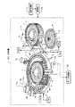
図2は、分析部24の構成を示した斜視図である。この分析部24は、標準試料や被検試料を収容する試料容器17と、この試料容器17を保持するサンプルディスク5とを備えている。また、標準試料や被検試料の各試料に含まれる検査項目の成分と反応する1試薬系及び2試薬系の第1試薬を収容する試薬容器6と、この試薬容器6を回動可能に保持する試薬ラック1aとを備えている。  FIG. 2 is a perspective view showing the configuration of theanalysis unit 24. Theanalysis unit 24 includes asample container 17 that accommodates a standard sample and a test sample, and asample disk 5 that holds thesample container 17. In addition, areagent container 6 containing a first reagent and a two-reagent first reagent that react with components of a test item included in each sample of a standard sample and a test sample, and thereagent container 6 are rotatably held. Reagent rack 1a.

また、試薬ラック1aに保持された試薬容器6内の第1試薬を保冷する試薬庫1と、2試薬系の第1試薬と対をなす第2試薬を収容する試薬容器7とを備えている。また、試薬容器7を回動可能に保持する試薬ラック2aと、この試薬ラック2aに保持された試薬容器7内の第2試薬を保冷する試薬庫2とを備えている。また、円周上に配置された複数の反応容器3を回転可能に保持する反応ディスク4を備えている。  In addition, areagent storage 1 that keeps the first reagent in thereagent container 6 held in the reagent rack 1a cold and a reagent container 7 that stores a second reagent that forms a pair with the first reagent of the two-reagent system are provided. . In addition, a reagent rack 2a that rotatably holds the reagent container 7 and areagent storage 2 that cools the second reagent in the reagent container 7 held in the reagent rack 2a are provided. Moreover, the reaction disk 4 which hold | maintains the somereaction container 3 arrange | positioned on the periphery rotatably is provided.

また、サンプル分注ポンプ16aの吸引及び吐出動作により、サンプルディスク5に保持された試料容器17内の試料を吸引して反応容器3内へ吐出する分注を行うサンプル分注プローブ16を備えている。また、サンプル分注プローブ16を回動及び上下移動可能に保持するサンプル分注アーム10を備えている。また、試料容器17内の試料とサンプル分注プローブ16との接触及び離間を検出する試料検出器16bと、サンプル分注プローブ16を洗浄する洗浄部70とを備えている。  In addition, asample dispensing probe 16 that performs dispensing to suck the sample in thesample container 17 held on thesample disk 5 and discharge it into thereaction container 3 by the suction and discharge operations of thesample dispensing pump 16a is provided. Yes. In addition, asample dispensing arm 10 that holds thesample dispensing probe 16 so as to be rotatable and vertically movable is provided. Further, asample detector 16 b that detects contact and separation between the sample in thesample container 17 and thesample dispensing probe 16 and acleaning unit 70 that cleans thesample dispensing probe 16 are provided.

また、第1試薬分注ポンプ14aの吸引及び吐出動作により、試薬ラック1aに保持された試薬容器6内の第1試薬を吸引して試料が吐出された反応容器3内に吐出する分注を行う第1試薬分注プローブ14を備えている。また、第1試薬分注プローブ14を回動及び上下移動可能に保持する第1試薬分注アーム8を備えている。また、試薬容器6内の第1試薬と第1試薬分注プローブ14との接触及び離間を検出する第1試薬検出器14bと、第1試薬分注プローブ14を洗浄する洗浄部80とを備えている。  Further, by the suction and discharge operation of the firstreagent dispensing pump 14a, the first reagent in thereagent container 6 held in the reagent rack 1a is sucked and dispensed into thereaction container 3 from which the sample has been discharged. A firstreagent dispensing probe 14 is provided. Moreover, the 1st reagent dispensing arm 8 which hold | maintains the 1streagent dispensing probe 14 so that rotation and a vertical movement are possible is provided. In addition, afirst reagent detector 14b that detects contact and separation between the first reagent in thereagent container 6 and the firstreagent dispensing probe 14 and acleaning unit 80 that cleans the firstreagent dispensing probe 14 are provided. ing.

また、反応容器3内に吐出された試料と第1試薬の混合液を撹拌する第1撹拌子18と、第1撹拌子18を回動及び上下移動可能に保持する第1撹拌アーム20とを備えている。また、混合液の撹拌終了毎に第1撹拌子18を洗浄する洗浄槽18aを備えている。また、第2試薬分注ポンプ15aの吸引及び吐出動作により、試薬ラック2aに保持された試薬容器7内の第2試薬を吸引して第1試薬が吐出された反応容器3内に吐出する分注を行う第2試薬分注プローブ15を備えている。  In addition, afirst stirrer 18 that stirs the mixed solution of the sample and the first reagent discharged into thereaction container 3, and afirst stirrer arm 20 that holds thefirst stirrer 18 so as to be rotatable and vertically movable. I have. Moreover, the washing tank 18a which wash | cleans the 1st stirringelement 18 whenever the stirring of a liquid mixture is complete | finished is provided. In addition, the secondreagent dispensing pump 15a sucks and discharges the second reagent in the reagent container 7 held in the reagent rack 2a to be discharged into thereaction container 3 from which the first reagent has been discharged. A secondreagent dispensing probe 15 for performing the injection is provided.

また、この第2試薬分注プローブ15を回動及び上下移動可能に保持する第2試薬分注アーム9を備えている。また、試薬容器7内の第2試薬と第2試薬分注プローブ15との接触及び離間を検出する第2試薬検出器15bと、第2試薬分注プローブ15を洗浄する洗浄部90とを備えている。  Further, a second reagent dispensing arm 9 that holds the secondreagent dispensing probe 15 so as to be rotatable and vertically movable is provided. In addition, asecond reagent detector 15 b that detects contact and separation between the second reagent in the reagent container 7 and the secondreagent dispensing probe 15, and acleaning unit 90 that cleans the secondreagent dispensing probe 15 are provided. ing.

また、反応容器3内の試料、第1試薬、及び第2試薬の混合液を撹拌する第2撹拌子19と、第2撹拌子19を回動及び上下移動可能に保持する第2撹拌アーム21と、混合液の撹拌終了毎に第2撹拌子19を洗浄する洗浄槽19aとを備えている。また、反応容器3内の混合液に光を照射して測定する測定部13と、測定部13で測定を終了した反応容器3内を洗浄する洗浄ノズル12とを備えている。  In addition, asecond stirrer 19 that stirs the mixed solution of the sample, the first reagent, and the second reagent in thereaction vessel 3, and asecond stirrer arm 21 that holds thesecond stirrer 19 so as to be rotatable and vertically movable. And awashing tank 19a for washing thesecond stirrer 19 every time the mixed solution is stirred. Moreover, themeasurement part 13 which irradiates and measures the liquid mixture in thereaction container 3 and the washing | cleaningnozzle 12 which wash | cleans thereaction container 3 which complete | finished the measurement in themeasurement part 13 are provided.

そして、測定部13は光を照射し、反応容器3内の標準試料や各被検試料を含む混合液を透過した光を検査項目の波長毎に検出する。そして、検出した検出信号に基づいて、例えば吸光度データで表される標準データや被検データを生成し、生成した標準データや被検データをデータ処理部35に出力する。  And themeasurement part 13 irradiates light, and detects the light which permeate | transmitted the liquid mixture containing the standard sample in thereaction container 3, and each test sample for every wavelength of an inspection item. Based on the detected detection signal, for example, standard data or test data represented by absorbance data is generated, and the generated standard data or test data is output to thedata processing unit 35.

駆動部30は、分析部24の各分析ユニットを駆動するための駆動源、この駆動源からの駆動力を各分析ユニットに伝達する機構等を備えている。そして、サンプルディスク5を駆動して試料容器17を移動する。また、試薬ラック1a,2aを夫々駆動して試薬容器6,7を回動する。また、反応ディスク4を駆動して反応容器3を回転移動する。  Thedrive unit 30 includes a drive source for driving each analysis unit of theanalysis unit 24, a mechanism for transmitting a drive force from the drive source to each analysis unit, and the like. Then, thesample disk 5 is driven to move thesample container 17. The reagent racks 1a and 2a are driven to rotate thereagent containers 6 and 7, respectively. Further, the reaction disk 4 is driven to rotate and move thereaction vessel 3.

また、サンプル分注アーム10、第1試薬分注アーム8、第1撹拌アーム20、第2試薬分注アーム9及び第2撹拌アーム21を夫々回動駆動及び上下駆動する。そして、サンプル分注プローブ16、第1試薬分注プローブ14、第1撹拌子18、第2試薬分注プローブ15及び第2撹拌子19を移動する。  In addition, thesample dispensing arm 10, the first reagent dispensing arm 8, thefirst stirring arm 20, the second reagent dispensing arm 9, and thesecond stirring arm 21 are rotated and vertically driven, respectively. Then, thesample dispensing probe 16, the firstreagent dispensing probe 14, the first stirringbar 18, the secondreagent dispensing probe 15, and the second stirringbar 19 are moved.

また、サンプル分注ポンプ16aを駆動して、サンプル分注プローブ16に試料の吸引及び吐出を行わせる。また、第1試薬分注ポンプ14aを駆動して、第1試薬分注プローブ14に第1試薬の吸引及び吐出を行わせる。また、第2試薬分注ポンプ15aを駆動して、第2試薬分注プローブ15に第2試薬の吸引及び吐出を行わせる。  Further, thesample dispensing pump 16a is driven to cause thesample dispensing probe 16 to suck and discharge the sample. Further, the firstreagent dispensing pump 14a is driven to cause the firstreagent dispensing probe 14 to suck and discharge the first reagent. Further, the secondreagent dispensing pump 15a is driven to cause the secondreagent dispensing probe 15 to suck and discharge the second reagent.

また、洗浄部70の各洗浄ユニットを駆動してサンプル分注プローブ16の洗浄を行わせる。また、洗浄部80の各洗浄ユニットを駆動して第1試薬分注プローブ14の洗浄を行わせる。また、洗浄部90の各洗浄ユニットを駆動して第2試薬分注プローブ15の洗浄を行わせる。  In addition, each cleaning unit of thecleaning unit 70 is driven to clean thesample dispensing probe 16. Further, each cleaning unit of thecleaning unit 80 is driven to clean the firstreagent dispensing probe 14. Further, each cleaning unit of thecleaning unit 90 is driven to clean the secondreagent dispensing probe 15.

分析制御部31は、分析部24のサンプル分注プローブ16を上死点の高さで水平方向に移動させ、サンプルディスク5上方の上停止位置で停止させる。次いで、上停止位置から下方向に移動させ、サンプル分注プローブ16の下端部が試料容器17内の試料と接触して試料検出器16bにより検出される吸引位置で試料を吸引させる。吸引位置で試料の吸引が行われた後、吸引位置から上停止位置まで移動させ、更に水平移動させて反応ディスク4上方の上停止位置で停止させる。次いで、上停止位置から下方向に移動させ、反応容器3内の底面に接触する吐出位置で試料を吐出させる。  Theanalysis control unit 31 moves thesample dispensing probe 16 of theanalysis unit 24 in the horizontal direction at the height of the top dead center and stops it at the upper stop position above thesample disk 5. Next, the sample is moved downward from the upper stop position, and the lower end portion of thesample dispensing probe 16 comes into contact with the sample in thesample container 17 to suck the sample at the suction position detected by thesample detector 16b. After the sample is aspirated at the aspiration position, the sample is moved from the aspiration position to the upper stop position, and further moved horizontally to stop at the upper stop position above the reaction disk 4. Next, the sample is moved downward from the upper stop position, and the sample is discharged at a discharge position in contact with the bottom surface in thereaction vessel 3.

同一試料の分注が終了した後、次の試料の分注を開始させる前に、洗浄部70によりサンプル分注プローブ16の洗浄を行わせる。そして、次の試料に影響を受ける検査項目が設定されていない場合、サンプル分注プローブ16を洗浄部70の第1の洗浄位置へ移動させ、第1の洗浄液を用いて洗浄を行わせる。また、次の試料に検査項目が設定されている場合、サンプル分注プローブ16を洗浄部70の第2の洗浄位置へ移動させ、第1の洗浄液よりも強力な洗浄力を有する第2の洗浄液を用いて洗浄を行わせる。  After the dispensing of the same sample is completed, thesample dispensing probe 16 is cleaned by thecleaning unit 70 before starting the dispensing of the next sample. And when the inspection item influenced by the following sample is not set, thesample dispensing probe 16 is moved to the 1st washing position of the washing | cleaningpart 70, and it wash | cleans using a 1st washing | cleaning liquid. When the inspection item is set for the next sample, thesample dispensing probe 16 is moved to the second cleaning position of thecleaning unit 70, and the second cleaning liquid has a stronger cleaning power than the first cleaning liquid. Use to clean.

また、分析制御部31は、分析部24の第1試薬分注プローブ14を上死点の高さで水平方向に移動させ、試薬ラック1a上方の上停止位置で停止させる。次いで、上停止位置から下方向に移動させ、第1試薬分注プローブ14の下端部が試薬容器6内の第1試薬と接触して第1試薬検出器14bにより検出される吸引位置で第1試料を吸引させる。吸引位置で第1試薬の吸引が行われた後、吸引位置から上停止位置まで移動させ、更に水平移動させて反応ディスク4の上停止位置で第1試薬を吐出させる。  Further, theanalysis control unit 31 moves the firstreagent dispensing probe 14 of theanalysis unit 24 in the horizontal direction at the height of the top dead center, and stops it at the upper stop position above the reagent rack 1a. Next, the firstreagent dispensing probe 14 is moved downward from the upper stop position, and the lower end of the firstreagent dispensing probe 14 comes into contact with the first reagent in thereagent container 6 and is detected at the first aspiration position detected by thefirst reagent detector 14b. Aspirate the sample. After the first reagent is aspirated at the aspiration position, the first reagent is moved from the aspiration position to the upper stop position, and further moved horizontally to discharge the first reagent at the upper stop position of the reaction disk 4.

第1試薬の分注が終了した後、次の第1試薬の分注を行わせる前に、洗浄部80により第1試薬分注プローブ14の洗浄を行わせる。そして、次の第1試薬の前に分注された第1試薬が影響を与える試薬であり、次の第1試薬がその影響を与える試薬から影響を受ける試薬である場合を除いて、第1試薬分注プローブ14を洗浄部80の第1の洗浄位置へ移動させ、第1の洗浄液を用いて洗浄を行わせる。また、次の第1試薬の前に分注された第1試薬が影響を与える試薬であり、次の第1試薬がその影響を与える試薬から影響を受ける試薬である場合、第1試薬分注プローブ14を洗浄部80の第2の洗浄位置へ移動させ、第2の洗浄液を用いて洗浄を行わせる。  After the first reagent has been dispensed, the firstreagent dispensing probe 14 is washed by thewashing unit 80 before the next first reagent is dispensed. The first reagent dispensed before the next first reagent is an affecting reagent, and the first reagent is a reagent that is affected by a reagent that affects the first reagent. Thereagent dispensing probe 14 is moved to the first cleaning position of thecleaning unit 80, and cleaning is performed using the first cleaning liquid. Further, when the first reagent dispensed before the next first reagent is an influential reagent, and the next first reagent is an influential reagent from the influential reagent, the first reagent is dispensed. Theprobe 14 is moved to the second cleaning position of thecleaning unit 80, and cleaning is performed using the second cleaning liquid.

更に、分析制御部31は、分析部24の第2試薬分注プローブ15を上死点の高さで水平方向に移動させ、試薬ラック2a上方の上停止位置で停止させる。次いで、上停止位置から下方向に移動させ、第2試薬分注プローブ15の下端部が試薬容器7内の第2試薬と接触して第2試薬検出器15bにより検出される吸引位置で停止させる。吸引位置で第2試薬の吸引が行われた後、吸引位置から上停止位置まで移動させ、更に水平移動させて反応ディスク4の上停止位置で第2試薬を吐出させる。  Further, theanalysis control unit 31 moves the secondreagent dispensing probe 15 of theanalysis unit 24 in the horizontal direction at the height of the top dead center, and stops it at the upper stop position above the reagent rack 2a. Next, the secondreagent dispensing probe 15 is moved downward from the upper stop position, and the lower end portion of the secondreagent dispensing probe 15 comes into contact with the second reagent in the reagent container 7 and is stopped at the suction position detected by thesecond reagent detector 15b. . After the second reagent is aspirated at the aspiration position, the second reagent is moved from the aspiration position to the upper stop position, and further moved horizontally to discharge the second reagent at the upper stop position of the reaction disk 4.

第2試薬の分注が終了した後、次の第2試薬の分注を行わせる前に、洗浄部90により第2試薬分注プローブ15の洗浄を行わせる。そして、次の第2試薬の前に分注された第2試薬が影響を与える試薬であり、次の第2試薬がその影響を与える試薬から影響を受ける試薬である場合を除いて、第2試薬分注プローブ15を洗浄部90の第1の洗浄位置へ移動させ、第1の洗浄液を用いて洗浄を行わせる。また、次の第2試薬の前に分注された第2試薬が影響を与える試薬であり、次の第2試薬がその影響を与える試薬から影響を受ける試薬である場合、第2試薬分注プローブ15を第2の洗浄位置へ移動させ、第2の洗浄液を用いて洗浄を行わせる。  After the second reagent is dispensed, the secondreagent dispensing probe 15 is washed by thewashing unit 90 before the next second reagent is dispensed. The second reagent dispensed before the next second reagent is a reagent that affects the second reagent, and the second reagent is a reagent that is influenced by the reagent that affects the second reagent. Thereagent dispensing probe 15 is moved to the first cleaning position of thecleaning unit 90, and cleaning is performed using the first cleaning liquid. In addition, when the second reagent dispensed before the next second reagent is an affecting reagent, and the next second reagent is a reagent influenced by the affecting reagent, the second reagent dispensing is performed. Theprobe 15 is moved to the second cleaning position, and cleaning is performed using the second cleaning liquid.

図1に示したデータ処理部35は、分析部24の測定部13で生成された標準データや被検データを処理して各検査項目の検量データや分析データを生成する演算部36と、演算部36で生成された標準データや分析データを保存するデータ記憶部37とを備えている。  Thedata processing unit 35 shown in FIG. 1 includes a calculation unit 36 that processes the standard data and test data generated by themeasurement unit 13 of theanalysis unit 24 to generate calibration data and analysis data for each inspection item, And a data storage unit 37 for storing the standard data and analysis data generated by the unit 36.

演算部36は、測定部13で生成された標準データ及びこの標準データの標準試料に対して予め設定された標準値から、標準値と標準データの関係を表す検量データを検査項目毎に生成し、生成した検量データを出力部40に出力すると共にデータ記憶部37に保存する。  The calculation unit 36 generates calibration data representing the relationship between the standard value and the standard data for each inspection item from the standard data generated by themeasurement unit 13 and the standard value preset for the standard sample of the standard data. The generated calibration data is output to the output unit 40 and stored in the data storage unit 37.

また、測定部13で生成された被検データに対応する検査項目の検量データをデータ記憶部37から読み出す。そして、読み出した検量データを用いて測定部13で生成された被検データから、濃度値や活性値で表される分析データを生成する。そして、生成した分析データを出力部40に出力すると共にデータ記憶部37に保存する。  In addition, the calibration data of the inspection item corresponding to the test data generated by themeasurement unit 13 is read from the data storage unit 37. Then, analysis data represented by a concentration value or an activity value is generated from the test data generated by themeasurement unit 13 using the read calibration data. The generated analysis data is output to the output unit 40 and stored in the data storage unit 37.

データ記憶部37は、ハードディスク等のメモリデバイスを備え、演算部36で生成された検量データを検査項目毎に保存する。また、演算部36で生成された各検査項目の分析データを被検試料毎に保存する。  The data storage unit 37 includes a memory device such as a hard disk, and stores the calibration data generated by the calculation unit 36 for each inspection item. Moreover, the analysis data of each inspection item generated by the calculation unit 36 is stored for each test sample.

出力部40は、データ処理部35の演算部36で生成された検量データや分析データを印刷出力する印刷部41及び表示出力する表示部42を備えている。そして、印刷部41は、プリンタなどを備え、演算部36で生成された検量データや分析データを予め設定されたフォーマットに従って、プリンタ用紙などに印刷する。  The output unit 40 includes aprinting unit 41 that prints and outputs calibration data and analysis data generated by the calculation unit 36 of thedata processing unit 35 and adisplay unit 42 that displays and outputs the data. Theprinting unit 41 includes a printer or the like, and prints the calibration data and analysis data generated by the calculation unit 36 on printer paper or the like according to a preset format.

表示部42は、CRTや液晶パネルなどのモニタを備え、演算部36で生成された検量データや分析データを表示する。また、各検査項目の分析パラメータである反応容器3内に吐出させる試料の量、第1試薬の量、及び第2試薬の量等の設定を行うための分析パラメータ設定画面を表示する。また、影響を受ける検査項目、影響を与える第1試薬及びこの試薬から影響を受ける第1試薬、並びに影響を与える第2試薬及びこの試薬から影響を受ける第2試薬の各汚染情報の設定を行うための汚染情報設定画面を表示する。また、各被検試料に検査項目を設定するための検査項目設定画面を表示する。  Thedisplay unit 42 includes a monitor such as a CRT or a liquid crystal panel, and displays the calibration data and analysis data generated by the calculation unit 36. In addition, an analysis parameter setting screen for setting the amount of the sample to be discharged into thereaction container 3, the amount of the first reagent, the amount of the second reagent, and the like, which are analysis parameters of each inspection item, is displayed. In addition, each contamination information of the affected test item, the affected first reagent and the affected first reagent, and the affected second reagent and the affected second reagent is set. Display the pollution information setting screen for In addition, an inspection item setting screen for setting inspection items for each test sample is displayed.

操作部50は、キーボード、マウス、ボタン、タッチキーパネルなどの入力デバイスを備え、検査項目毎に分析パラメータを設定するための入力を行う。また、汚染情報を設定するための入力を行う。また、各被検試料に検査項目を設定するための入力を行う。  Theoperation unit 50 includes input devices such as a keyboard, a mouse, a button, and a touch key panel, and performs input for setting analysis parameters for each inspection item. Also, input for setting pollution information is performed. In addition, an input for setting an inspection item for each test sample is performed.

システム制御部60は、CPU及び記憶回路を備え、操作部50から入力された各検査項目の分析パラメータ、汚染情報、各被検試料に設定された検査項目の情報等の入力情報を記憶回路に記憶した後、これらの入力情報に基づいて、分析制御部31、データ処理部35、及び出力部40を統括してシステム全体を制御する。  Thesystem control unit 60 includes a CPU and a storage circuit. Input information such as analysis parameters, contamination information, and inspection item information set for each test sample input from theoperation unit 50 is input to the storage circuit. After the storage, based on these input information, theanalysis control unit 31, thedata processing unit 35, and the output unit 40 are integrated to control the entire system.

次に、図2及び図3を参照して、分析部24におけるサンプル分注ポンプ16a及びサンプル分注プローブ16について説明する。
図3は、吸引位置で試料の吸引を行うサンプル分注プローブ16を示した図である。このサンプル分注プローブ16は、内部が例えば純水等の圧力伝達媒体で満たされ、サンプル分注ポンプ16aと圧力伝達媒体で満たされたチューブ161で連通している。また、上端部がサンプル分注アーム10に保持されている。
Next, thesample dispensing pump 16a and thesample dispensing probe 16 in theanalysis unit 24 will be described with reference to FIGS.
FIG. 3 is a diagram showing thesample dispensing probe 16 that sucks the sample at the suction position. Thesample dispensing probe 16 is filled with a pressure transmission medium such as pure water, and communicates with thesample dispensing pump 16a and atube 161 filled with the pressure transmission medium. The upper end portion is held by thesample dispensing arm 10.

そして、サンプル分注プローブ16は、下端部がサンプルディスク5に保持された試料容器17内の試料と接触することにより試料検出器16bで検出される吸引位置A1で停止する。吸引位置A1で停止した後、駆動部30によるサンプル分注ポンプ16aの吸引駆動により試料を吸引する。  Thesample dispensing probe 16 stops at the suction position A1 detected by thesample detector 16b when the lower end of thesample dispensing probe 16 comes into contact with the sample in thesample container 17 held by thesample disk 5. After stopping at the suction position A1, the sample is sucked by the suction drive of thesample dispensing pump 16a by thedrive unit 30.

このように、サンプル分注プローブ16を試料検出器16bにより検出される吸引位置A1で試料を吸引させることにより、試料の吸引に不要なサンプル分注プローブ16外面の下端部以外の部分と試料との接触を防いで、サンプル分注プローブ16外面の試料による汚染の範囲を低減することができる。  In this way, by sucking the sample at the suction position A1 detected by thesample detector 16b with thesample dispensing probe 16, a portion other than the lower end portion of the outer surface of thesample dispensing probe 16 that is not necessary for sucking the sample, and the sample The range of contamination by the sample on the outer surface of thesample dispensing probe 16 can be reduced.

次に、図2乃至図7を参照して、洗浄部70の構成の一例を説明する。
図4は、洗浄部70の構成を示した図である。この洗浄部70は、サンプル分注プローブ16の洗浄を行うための第1及び第2の洗浄液を供給する供給部71を備えている。また、図5に示すように、サンプルディスク5と反応ディスク4の間に配置され、供給部71により供給される第1及び第2の洗浄液を用いてサンプル分注プローブ16の洗浄が行われる洗浄槽72を備えている。また、洗浄槽72に供給された第2の洗浄液を検出する洗浄液検出器73を備えている。
Next, an example of the configuration of thecleaning unit 70 will be described with reference to FIGS.
FIG. 4 is a diagram illustrating the configuration of thecleaning unit 70. Thecleaning unit 70 includes a supply unit 71 that supplies first and second cleaning liquids for cleaning thesample dispensing probe 16. In addition, as shown in FIG. 5, the cleaning is performed between thesample disk 5 and the reaction disk 4, and thesample dispensing probe 16 is cleaned using the first and second cleaning liquids supplied by the supply unit 71. A tank 72 is provided. In addition, a cleaningliquid detector 73 that detects the second cleaning liquid supplied to the cleaning tank 72 is provided.

供給部71は、サンプル分注プローブ16に第1の洗浄液を供給する内部洗浄ポンプ711と、洗浄槽72に第1の洗浄液を供給する第1の供給ポンプ712とを備えている。また、洗浄液検出器73の検出に基づいて洗浄槽72への第2の洗浄液の供給及び供給の停止を行う第2の供給ポンプ713を備えている。  The supply unit 71 includes aninternal cleaning pump 711 that supplies the first cleaning liquid to thesample dispensing probe 16, and afirst supply pump 712 that supplies the first cleaning liquid to the cleaning tank 72. In addition, asecond supply pump 713 that supplies and stops the supply of the second cleaning liquid to the cleaning tank 72 based on the detection by the cleaningliquid detector 73 is provided.

内部洗浄ポンプ711は、例えば純水装置110から純水を吸引し、吸引した純水を第1の洗浄液としてサンプル分注ポンプ16aを介してサンプル分注プローブ16に供給する。また、第1の供給ポンプ712は純水装置110から純水を吸引し、吸引した純水を第1の洗浄液として洗浄槽72に供給する。  Theinternal cleaning pump 711 sucks pure water from thepure water device 110, for example, and supplies the sucked pure water to thesample dispensing probe 16 through thesample dispensing pump 16a as a first cleaning liquid. Thefirst supply pump 712 sucks pure water from thepure water device 110 and supplies the sucked pure water to the cleaning tank 72 as a first cleaning liquid.

第2の供給ポンプ713は、分析部24の各分析ユニットが配置された位置よりも下方に配置された例えばアルカリ性の洗剤を収容する洗剤容器25から洗剤を吸引する。また、純水装置110から純水を吸引する。そして、吸引した洗剤を純水で希釈した液を第2の洗浄液として洗浄槽72に供給する。  Thesecond supply pump 713 sucks the detergent from thedetergent container 25 that houses, for example, alkaline detergent disposed below the position where each analysis unit of theanalysis unit 24 is disposed. Further, pure water is sucked from thepure water device 110. Then, a liquid obtained by diluting the sucked detergent with pure water is supplied to the cleaning tank 72 as a second cleaning liquid.

洗浄槽72は、供給部71の第1の供給ポンプ712により第1の洗浄液が供給される第1の洗浄槽75と、第2の供給ポンプ713により第2の洗浄液が供給される第2の洗浄槽76と、第1及び第2の洗浄槽75,76を保持する洗浄槽本体77とにより構成される。  The cleaning tank 72 includes afirst cleaning tank 75 to which the first cleaning liquid is supplied by thefirst supply pump 712 of the supply unit 71, and a second cleaning liquid to which the second cleaning liquid is supplied by thesecond supply pump 713. Thecleaning tank 76 includes acleaning tank body 77 that holds the first andsecond cleaning tanks 75 and 76.

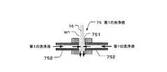
図6は、第1の洗浄槽75の構成を示した断面図である。この第1の洗浄槽75は、サンプルディスク5上方の上停止位置と反応ディスク4上方の上停止位置間を水平移動するサンプル分注プローブ16が通過可能なように設けた通路751を有する。また、通路751を挟むように対向して横設された2つの吐出管752を有する。この2つの吐出管752は、第1の供給ポンプ712により供給された第1の洗浄液が流入する入口と、流入した第1の洗浄液を吐出する通路751側に配置された吐出口を有する。そして、試料と接触した下端部が2つの吐出管752の間となる第1の洗浄位置W1で停止したサンプル分注プローブ16の洗浄が行われる。  FIG. 6 is a cross-sectional view showing the configuration of thefirst cleaning tank 75. Thefirst cleaning tank 75 has apassage 751 provided so that thesample dispensing probe 16 that horizontally moves between the upper stop position above thesample disk 5 and the upper stop position above the reaction disk 4 can pass therethrough. In addition, there are twodischarge pipes 752 that are arranged opposite to each other so as to sandwich thepassage 751 therebetween. The twodischarge pipes 752 have an inlet through which the first cleaning liquid supplied by thefirst supply pump 712 flows and a discharge port arranged on the side of thepassage 751 through which the first cleaning liquid flows in. Then, thesample dispensing probe 16 stopped at the first cleaning position W1 where the lower end portion in contact with the sample is between the twodischarge pipes 752 is cleaned.

図7は、第2の洗浄槽76、並びに洗浄槽本体77及び洗浄液検出器73の構成を示した図である。そして、図7(a)は第2の洗浄槽76並びに洗浄槽本体77の一部及び洗浄液検出器73の平面図を示し、図7(b)は図7(a)に示したA−A線矢視断面図を示している。  FIG. 7 is a diagram showing the configuration of thesecond cleaning tank 76, the cleaning tankmain body 77, and the cleaningliquid detector 73. 7A shows a plan view of thesecond cleaning tank 76, a part of the cleaning tankmain body 77, and the cleaningliquid detector 73, and FIG. 7B shows the AA shown in FIG. 7A. A cross-sectional view taken along line arrow is shown.

第2の洗浄槽76は、第2の供給ポンプ713とチューブ78で連通し、第2の供給ポンプ713により供給された第2の洗浄液が流入する流入管761を備えている。また、流入管761から流出した第2の洗浄液を貯留する第1及び第2の貯留室762,765を備えている。また、第1の貯留室762と第2の貯留室765を隔離するように設けた隔離部材763を備えている。また、第1の貯留室762と第2の貯留室765の間を連通する隔離部材763の下部に形成された連通孔764を備えている。  Thesecond cleaning tank 76 includes aninflow pipe 761 that communicates with thesecond supply pump 713 through thetube 78 and into which the second cleaning liquid supplied by thesecond supply pump 713 flows. Further, first andsecond storage chambers 762 and 765 for storing the second cleaning liquid flowing out from theinflow pipe 761 are provided. In addition, anisolation member 763 provided to isolate thefirst storage chamber 762 and thesecond storage chamber 765 is provided. In addition, acommunication hole 764 formed in the lower portion of theisolation member 763 that communicates between thefirst storage chamber 762 and thesecond storage chamber 765 is provided.

流入管761は、第2の供給ポンプ713からの第2の洗浄液が下端から流入し、第1の貯留室762の底部に設けた開口部76aから上方に流出するように配設されている。また、開口部76aは、隔離部材763から隔てて設けられている。また、隔離部材763は、開口部76aの直上から外れて設けられている。また、第2の貯留室765は、サンプルディスク5上方の上停止位置と反応ディスク4上方の上停止位置間を水平移動するサンプル分注プローブ16の軌道の下方に配置されている。  Theinflow pipe 761 is arranged so that the second cleaning liquid from thesecond supply pump 713 flows in from the lower end and flows out upward from an opening 76 a provided in the bottom of thefirst storage chamber 762. Further, theopening 76a is provided separately from theisolation member 763. Further, the separatingmember 763 is provided so as to be detached from immediately above theopening 76a. Thesecond storage chamber 765 is disposed below the trajectory of thesample dispensing probe 16 that horizontally moves between the upper stop position above thesample disk 5 and the upper stop position above the reaction disk 4.

そして、開口部76aから第1の貯留室762へ流入した第2の洗浄液の一部が連通孔764から第2の貯留室765に流出することにより、第1及び第2の貯留室762,765に第2の洗浄液が貯留される。この第2の貯留室765に貯留された第2の洗浄液をサンプル分注プローブ16が吸引することにより洗浄が行われる。  Then, a part of the second cleaning liquid that has flowed into thefirst storage chamber 762 from theopening 76a flows out from thecommunication hole 764 to thesecond storage chamber 765, whereby the first andsecond storage chambers 762, 765 are obtained. The second cleaning liquid is stored in Cleaning is performed when thesample dispensing probe 16 sucks the second cleaning liquid stored in thesecond storage chamber 765.

洗浄槽本体77の底部には、第1の洗浄槽75で洗浄に使用された第1の洗浄液や、第2の洗浄槽76で洗浄に使用された第2の洗浄液等が廃液として外部に排出される排液管771が設けられている。  At the bottom of thecleaning tank body 77, the first cleaning liquid used for cleaning in thefirst cleaning tank 75, the second cleaning liquid used for cleaning in thesecond cleaning tank 76, etc. are discharged to the outside as waste liquid. Adrainage pipe 771 is provided.

洗浄液検出器73は、第2の洗浄槽76の第2の貯留室765に配置された一対の導体731及びこの導体731と接続された検出回路732を備えている。そして、第2の貯留室765に貯留された第2の洗浄液が所定量に達したとき、一対の導体731間の電気抵抗の低下を検出回路732が検出することにより、第2の洗浄液と導体731との接触を検出する。  The cleaningliquid detector 73 includes a pair ofconductors 731 disposed in thesecond storage chamber 765 of thesecond cleaning tank 76 and adetection circuit 732 connected to theconductors 731. When the second cleaning liquid stored in thesecond storage chamber 765 reaches a predetermined amount, thedetection circuit 732 detects a decrease in electrical resistance between the pair ofconductors 731, whereby the second cleaning liquid and the conductor are detected. Contact with 731 is detected.

また、洗浄液検出器73は、第2の貯留室765の第2の洗浄液が減少して一対の導体731間の電気抵抗の上昇を検出回路732が検出することにより、第2の洗浄液と導体731との離間を検出する。第2の供給ポンプ713では、洗浄液検出器73が第2の貯留室765の第2の洗浄液と導体731との離間を検出したとき、第2の洗浄液を第2の洗浄槽76に供給する。  The cleaningliquid detector 73 detects the increase in the electrical resistance between the pair ofconductors 731 when the second cleaning liquid in thesecond storage chamber 765 decreases and thedetection circuit 732 detects the second cleaning liquid and theconductor 731. Detecting the separation from. In thesecond supply pump 713, when the cleaningliquid detector 73 detects the separation between the second cleaning liquid in thesecond storage chamber 765 and theconductor 731, the second cleaning liquid is supplied to thesecond cleaning tank 76.

このように、洗浄液検出器73の検出に基づいて第1及び第2の貯留室762,765で第2の洗浄液を貯留する量を、サンプル分注プローブ16が第2の洗浄液を洗浄に必要な1回又は数回の少ない回数吸引する量にすることにより、第2の洗浄槽76の小型化を図ることができる。  Thus, based on the detection of the cleaningliquid detector 73, the amount of the second cleaning liquid stored in the first andsecond storage chambers 762, 765 is determined by thesample dispensing probe 16 for cleaning the second cleaning liquid. By making the amount to be sucked once or several times, thesecond cleaning tank 76 can be downsized.

次に、図2乃至図10を参照して、サンプル分注プローブ16の洗浄の動作について説明する。  Next, the operation of cleaning thesample dispensing probe 16 will be described with reference to FIGS.

図8は、第1の洗浄槽75で行われるサンプル分注プローブ16の洗浄の様子を示した図である。このサンプル分注プローブ16は、同一試料の分注を終了した後、次の試料に影響を受ける検査項目が設定されていない場合、次の試料を分注する前に第1の洗浄槽75の第1の洗浄位置W1で停止する。  FIG. 8 is a view showing a state of cleaning thesample dispensing probe 16 performed in thefirst cleaning tank 75. After the dispensing of the same sample is completed, thesample dispensing probe 16 has afirst cleaning tank 75 before dispensing the next sample if no inspection item affected by the next sample is set. Stop at the first cleaning position W1.

サンプル分注プローブ16が第1の洗浄位置W1停止した後、内部洗浄ポンプ711は、サンプル分注プローブ16に第1の洗浄液を供給する。サンプル分注プローブ16は、内部洗浄ポンプ711から供給された第1の洗浄液を吐出する。また、第1の供給ポンプ712は、第1の洗浄液を第1の洗浄槽75に供給する。第1の洗浄槽75は、第1の供給ポンプ712から供給された第1の洗浄液を吐出する。第1の洗浄槽75から吐出された第1の洗浄液は、サンプル分注プローブ16の下端部外面に当たって落下する。サンプル分注プローブ16から吐出された第1の洗浄液及びンプル分注プローブ16に当たって落下した第1の洗浄液は、洗浄槽本体77の排液管771から排出される。  After thesample dispensing probe 16 stops at the first washing position W1, theinternal washing pump 711 supplies the first washing liquid to thesample dispensing probe 16. Thesample dispensing probe 16 discharges the first cleaning liquid supplied from theinternal cleaning pump 711. Thefirst supply pump 712 supplies the first cleaning liquid to thefirst cleaning tank 75. Thefirst cleaning tank 75 discharges the first cleaning liquid supplied from thefirst supply pump 712. The first cleaning liquid discharged from thefirst cleaning tank 75 hits the outer surface of the lower end portion of thesample dispensing probe 16 and falls. The first cleaning liquid discharged from thesample dispensing probe 16 and the first cleaning liquid that has fallen on thesample dispensing probe 16 are discharged from thedrain pipe 771 of thecleaning tank body 77.

このように、サンプル分注プローブ16から第1の洗浄液を吐出させることにより、試料と接触したサンプル分注プローブ16内面に付着した試料を洗い落とすことができる。また、サンプル分注プローブ16の下端部外面に第1の洗浄液を当てることにより、サンプル分注プローブ外面に付着した試料を洗い落とすことができる。  In this way, by discharging the first cleaning liquid from thesample dispensing probe 16, the sample attached to the inner surface of thesample dispensing probe 16 in contact with the sample can be washed away. Moreover, the sample adhering to the outer surface of the sample dispensing probe can be washed away by applying the first cleaning liquid to the outer surface of the lower end of thesample dispensing probe 16.

図9は、第2の洗浄槽76に供給された第2の洗浄液の様子を示した図である。そして、図9(a)は第2の洗浄槽76に供給されているときの第2の洗浄液の様子を示し、図9(b)は第2の洗浄槽76に貯留された第2の洗浄液の様子を示している。  FIG. 9 is a view showing the state of the second cleaning liquid supplied to thesecond cleaning tank 76. 9A shows the state of the second cleaning liquid when it is supplied to thesecond cleaning tank 76, and FIG. 9B shows the second cleaning liquid stored in thesecond cleaning tank 76. The state of is shown.

第2の供給ポンプ713と第2の洗浄槽76間を連通しているチューブ78は、駆動部30の駆動源等の熱により外部の温度よりも高い温度になる。このため、チューブ78内では第2の洗浄液に溶け込んでいた気体の溶解度が低下して気泡が生じる。  Thetube 78 communicating between thesecond supply pump 713 and thesecond cleaning tank 76 becomes a temperature higher than the external temperature due to the heat of the drive source of thedrive unit 30. For this reason, in thetube 78, the solubility of the gas dissolved in the second cleaning liquid is lowered to generate bubbles.

第2の供給ポンプ713は、第2の洗浄液を第2の洗浄槽76に供給する。第2の供給ポンプ713から供給された第2の洗浄液はチューブ78内で発生した気泡と共に、第2の洗浄槽76の流入管761に導かれて第1の貯留室762に流入する。そして、第1の貯留室762に流入した気泡は上昇し、第1の貯留室762に流入した第2の洗浄液の一部は連通孔764から第2の貯留室765へ流入する。  Thesecond supply pump 713 supplies the second cleaning liquid to thesecond cleaning tank 76. The second cleaning liquid supplied from thesecond supply pump 713 is guided to theinflow pipe 761 of thesecond cleaning tank 76 and flows into thefirst storage chamber 762 together with the bubbles generated in thetube 78. Then, the bubbles flowing into thefirst storage chamber 762 rise, and a part of the second cleaning liquid that flows into thefirst storage chamber 762 flows into thesecond storage chamber 765 from thecommunication hole 764.

洗浄液検出器73は、第2の貯留室765へ流入した第2の洗浄液が所定量に達したとき、第2の洗浄液の液面と導体731との接触を検出する。第2の供給ポンプ713は、洗浄液検出器73が第2の洗浄液と導体731との接触を検出したとき、第2の洗浄槽76への第2の洗浄液の供給を停止する。  The cleaningliquid detector 73 detects contact between the liquid surface of the second cleaning liquid and theconductor 731 when the second cleaning liquid flowing into thesecond storage chamber 765 reaches a predetermined amount. Thesecond supply pump 713 stops the supply of the second cleaning liquid to thesecond cleaning tank 76 when the cleaningliquid detector 73 detects the contact between the second cleaning liquid and theconductor 731.

第2の洗浄液の供給が停止された後、第1及び第2の貯留室762,765には、流入した第2の洗浄液が貯留されている。そして、第1の貯留室762に貯留された第2の洗浄液の液面には上昇した気泡が滞留している。第2の洗浄液に界面活性剤が含まれていると、多量の気泡が滞留することになる。また、第2の貯留室765には、導体731と接触した状態で第2の洗浄液が貯留されている。  After the supply of the second cleaning liquid is stopped, the second cleaning liquid that has flowed in is stored in the first andsecond storage chambers 762 and 765. The raised bubbles stay on the liquid surface of the second cleaning liquid stored in thefirst storage chamber 762. If the surfactant is contained in the second cleaning liquid, a large amount of bubbles will stay. Thesecond storage chamber 765 stores the second cleaning liquid in contact with theconductor 731.

このように、隔離部材763を開口部76aの直上から外れて設け且つ開口部76aから隔てて設け、隔離部材763の下部に連通孔764を形成することにより、開口部76aから第1の貯留室762に流入して上方に流れる第2の洗浄液に含まれる気泡を上昇させることができるため、第1の貯留室762で気泡が除去された第2の洗浄液を連通孔764から第2の貯留室765へ流入させることができる。これにより、洗浄液検出器73の気泡検出による誤検出を防ぐことができるため、第2の貯留室765にサンプル分注プローブ16の洗浄に必要な量の第2の洗浄液を貯留させることができる。  As described above, theseparation member 763 is provided off theopening 76a and spaced from theopening 76a, and thecommunication hole 764 is formed in the lower portion of theseparation member 763, whereby the first storage chamber is formed from theopening 76a. Since the bubbles contained in the second cleaning liquid flowing into 762 and flowing upward can be raised, the second cleaning liquid from which bubbles have been removed in thefirst storage chamber 762 is passed through thecommunication hole 764 to the second storage chamber. 765. Accordingly, erroneous detection due to bubble detection by the cleaningliquid detector 73 can be prevented, and therefore the second cleaning liquid in an amount necessary for cleaning thesample dispensing probe 16 can be stored in thesecond storage chamber 765.

なお、第1の貯留室762を形成している隔離部材763及び底部以外の側部の連通孔764よりも上方に開口部を設け、流入管761を第2の供給ポンプ713からの第2の洗浄液が前記開口部から水平又は斜め上方に向けて流出するように前記側部に横設して実施するようにしてもよい。これにより、開口部から第1の貯留室762に流入した第2の洗浄液に含まれる気泡を連通孔764よりも上方の位置から上昇させることができるため、第1の貯留室762で気泡が除去された第2の洗浄液を連通孔764から第2の貯留室765へ流入させることができる。  Note that an opening is provided above theisolation member 763 forming thefirst storage chamber 762 and theside communication hole 764 other than the bottom, and theinflow pipe 761 is connected to thesecond supply pump 713 from thesecond supply hole 713. The cleaning liquid may be installed horizontally on the side portion so as to flow out from the opening portion horizontally or obliquely upward. Accordingly, since the bubbles contained in the second cleaning liquid that has flowed into thefirst storage chamber 762 from the opening can be raised from a position above thecommunication hole 764, the bubbles are removed in thefirst storage chamber 762. The second cleaning liquid thus made can flow into thesecond storage chamber 765 from thecommunication hole 764.

図10は、第2の洗浄槽76で行われるサンプル分注プローブ16の洗浄の様子を示した図である。
サンプル分注プローブ16は、同一試料の分注を終了した後、次の試料に影響を受ける検査項目が設定されている場合、次の試料を分注する前に第2の洗浄槽76の第2の貯留室765の上方の上停止位置から下方へ移動する。そして、下端部が第2の貯留室765の第2の洗浄液と接触して試料検出器16bにより検出される第2の洗浄位置W2で停止し、試料と接触した内面の洗浄に必要な所定量の第2の洗浄液を吸引する。
FIG. 10 is a diagram illustrating a state of cleaning of thesample dispensing probe 16 performed in thesecond cleaning tank 76.
After the dispensing of the same sample is completed, thesample dispensing probe 16 has asecond cleaning tank 76 in thesecond washing tank 76 before dispensing the next sample when an inspection item affected by the next sample is set. It moves downward from the upper stop position above thesecond storage chamber 765. Then, the lower end portion comes into contact with the second cleaning liquid in thesecond storage chamber 765 and stops at the second cleaning position W2 detected by thesample detector 16b, and a predetermined amount necessary for cleaning the inner surface in contact with the sample. Aspirate the second cleaning solution.

このように、気泡が除去された第2の洗浄液を第2の貯留室765に貯留させることにより、試料検出器16bの気泡検出による誤検出を防ぐことができる。これにより、外面洗浄に必要な位置でサンプル分注プローブ16を停止させ、内面洗浄に必要な量の第2の洗浄液をサンプル分注プローブ16に吸引させることができる。  In this way, by storing the second cleaning liquid from which bubbles have been removed in thesecond storage chamber 765, it is possible to prevent erroneous detection due to bubble detection by thesample detector 16b. Thereby, thesample dispensing probe 16 can be stopped at a position necessary for the outer surface cleaning, and thesample dispensing probe 16 can suck the amount of the second cleaning liquid necessary for the inner surface cleaning.

洗浄液検出器73は、サンプル分注プローブ16の第2の洗浄液の吸引により、導体731間の電気抵抗が上昇して第2の貯留室765に貯留された第2の洗浄液と導体731との離間を検出する。第2の供給ポンプ713は、洗浄液検出器73が第2の洗浄液と導体731との離間を検出したとき、第2の洗浄槽76へ第2の洗浄液を供給する。そして、洗浄液検出器73が第2の洗浄液と導体731との接触を検出したとき、第2の洗浄液の供給を停止する。  The cleaningliquid detector 73 increases the electrical resistance between theconductors 731 due to the suction of the second cleaning liquid from thesample dispensing probe 16, and separates theconductor 731 from the second cleaning liquid stored in thesecond storage chamber 765. Is detected. Thesecond supply pump 713 supplies the second cleaning liquid to thesecond cleaning tank 76 when the cleaningliquid detector 73 detects the separation between the second cleaning liquid and theconductor 731. Then, when the cleaningliquid detector 73 detects the contact between the second cleaning liquid and theconductor 731, the supply of the second cleaning liquid is stopped.

このように、洗浄液検出器73の検出に基づいて第2の洗浄液を第2の洗浄槽76に供給することが可能となり、第2の洗浄液を補充する作業やこの作業のために分析部24の動作を停止させる必要がないため、検査時間や手間を低減することができる。  As described above, the second cleaning liquid can be supplied to thesecond cleaning tank 76 based on the detection by the cleaningliquid detector 73, and the second cleaning liquid is replenished or theanalysis unit 24 performs the work. Since it is not necessary to stop the operation, the inspection time and labor can be reduced.

第2の洗浄位置W2で第2の洗浄液を吸引したサンプル分注プローブ16は、第1の洗浄位置W1へ移動し、第1の洗浄位置W1で第2の洗浄液を吐出する。サンプル分注プローブ16が第2の洗浄液を吐出した後、内部洗浄ポンプ711はサンプル分注プローブ16に第1の洗浄液を供給し、サンプル分注プローブ16は内部洗浄ポンプ711から供給された第1の洗浄液を吐出する。また、第1の供給ポンプ712は第1の洗浄液を第1の洗浄槽75に供給し、第1の洗浄槽75は第1の供給ポンプ712から供給された第1の洗浄液を吐出する。そして、第1の洗浄槽75での洗浄が終了した後、次の試料を分注する。  Thesample dispensing probe 16 that has sucked the second cleaning liquid at the second cleaning position W2 moves to the first cleaning position W1, and discharges the second cleaning liquid at the first cleaning position W1. After thesample dispensing probe 16 discharges the second cleaning liquid, theinternal cleaning pump 711 supplies the first cleaning liquid to thesample dispensing probe 16, and thesample dispensing probe 16 is supplied from theinternal cleaning pump 711. Discharge the cleaning liquid. Thefirst supply pump 712 supplies the first cleaning liquid to thefirst cleaning tank 75, and thefirst cleaning tank 75 discharges the first cleaning liquid supplied from thefirst supply pump 712. Then, after the cleaning in thefirst cleaning tank 75 is completed, the next sample is dispensed.

このように、サンプル分注プローブ16から第1の洗浄液を吐出させることにより、サンプル分注プローブ16内面に残留する第2の洗浄液を洗い落とすことができる。また、サンプル分注プローブ16の下端部外面に第1の洗浄液を当てることにより、サンプル分注プローブ外面に残留する第2の洗浄液を洗い落とすことができる。  In this way, by discharging the first cleaning liquid from thesample dispensing probe 16, the second cleaning liquid remaining on the inner surface of thesample dispensing probe 16 can be washed off. Further, by applying the first cleaning liquid to the outer surface of the lower end of thesample dispensing probe 16, the second cleaning liquid remaining on the outer surface of the sample dispensing probe can be washed away.

なお、洗剤容器25に収容された洗剤とは異なる例えば酸性の洗剤を収容する洗剤容器、この洗剤容器内の洗剤及び純水を吸引して洗剤を純水で希釈した液を第3の洗浄液として供給する第3の供給ポンプ、第3の供給ポンプにより供給される第3の洗浄液を貯留する第2の洗浄槽76と同様に構成される第3の洗浄槽、及び第3の洗浄槽に貯留された第3の洗浄液を検出する第3の洗浄液検出器を設け、第2の洗浄液で洗浄する場合と同様にして第2の洗浄液では十分に洗い落とすことができない汚れを第3の洗浄液を用いてサンプル分注プローブ16を洗浄するように実施してもよい。  In addition, the detergent container which accommodates the detergent different from the detergent accommodated in thedetergent container 25, for example, the detergent in this detergent container, and the liquid which attracted | sucked the pure water and diluted the detergent with the pure water are used as 3rd washing | cleaning liquid 3rd supply pump to supply, 3rd washing tank comprised similarly to the2nd washing tank 76 which stores the 3rd washing liquid supplied by the 3rd supply pump, and storage in the 3rd washing tank A third cleaning liquid detector for detecting the third cleaning liquid is provided, and the third cleaning liquid is used to remove stains that cannot be sufficiently washed away with the second cleaning liquid in the same manner as in the case of cleaning with the second cleaning liquid. You may implement so that thesample dispensing probe 16 may be wash | cleaned.

次に、図2乃至図11を参照して、洗浄部80の構成の一例を説明する。  Next, an example of the configuration of thecleaning unit 80 will be described with reference to FIGS.

図11は、洗浄部80の構成を示した図である。この洗浄部80は、第1試薬分注プローブ14の洗浄を行うための第1及び第2の洗浄液を供給する供給部81を備えている。また、分析部24の試薬ラック1aと反応ディスク4の間に配置され、供給部81により供給される第1及び第2の洗浄液で第1試薬分注プローブ14の洗浄が行われる洗浄槽82を備えている。また、洗浄槽82に供給された第2の洗浄液を検出する洗浄液検出器83を備えている。  FIG. 11 is a diagram illustrating a configuration of thecleaning unit 80. Thecleaning unit 80 includes a supply unit 81 that supplies first and second cleaning liquids for cleaning the firstreagent dispensing probe 14. A cleaning tank 82 is disposed between the reagent rack 1a of theanalysis unit 24 and the reaction disk 4, and the firstreagent dispensing probe 14 is cleaned with the first and second cleaning liquids supplied by the supply unit 81. I have. In addition, a cleaningliquid detector 83 that detects the second cleaning liquid supplied to the cleaning tank 82 is provided.

供給部81は、第1試薬分注プローブ14に第1の洗浄液を供給する内部洗浄ポンプ811と、洗浄槽82に第1の洗浄液を供給する第1の供給ポンプ812とを備えている。また、洗浄液検出器83の検出に基づいて洗浄槽82への第2の洗浄液の供給及び供給の停止を行う第2の供給ポンプ813を備えている。  The supply unit 81 includes aninternal cleaning pump 811 that supplies the first cleaning liquid to the firstreagent dispensing probe 14 and afirst supply pump 812 that supplies the first cleaning liquid to the cleaning tank 82. In addition, asecond supply pump 813 that supplies and stops the supply of the second cleaning liquid to the cleaning tank 82 based on the detection by the cleaningliquid detector 83 is provided.

内部洗浄ポンプ811は、純水装置110から吸引した純水を第1の洗浄液として第1試薬分注ポンプ14aを介して第1試薬分注プローブ14に供給する。また、第1の供給ポンプ812は純水装置110から吸引した純水を第1の洗浄液として洗浄槽82に供給する。また、第2の供給ポンプ813は、洗剤容器25から吸引した洗剤を純水装置110から吸引した純水で希釈した液を第2の洗浄液として洗浄槽82に供給する。  Theinternal cleaning pump 811 supplies the pure water sucked from thepure water device 110 to the firstreagent dispensing probe 14 through the firstreagent dispensing pump 14a as the first cleaning liquid. Thefirst supply pump 812 supplies the pure water sucked from thepure water device 110 to the cleaning tank 82 as the first cleaning liquid. Further, thesecond supply pump 813 supplies a liquid obtained by diluting the detergent sucked from thedetergent container 25 with the pure water sucked from thepure water device 110 to the cleaning tank 82 as the second cleaning liquid.

洗浄槽82は、第1の供給ポンプ812により第1の洗浄液が供給される第1の洗浄槽85と、第2の供給ポンプ813により第2の洗浄液が供給される第2の洗浄槽86と、第1及び第2の洗浄槽85,86を保持する洗浄槽本体87とにより構成される。  The cleaning tank 82 includes afirst cleaning tank 85 to which a first cleaning liquid is supplied by afirst supply pump 812, and asecond cleaning tank 86 to which a second cleaning liquid is supplied by asecond supply pump 813. Thecleaning tank body 87 holds the first andsecond cleaning tanks 85 and 86.

第1の洗浄槽85は洗浄部70の第1の洗浄槽75と同様に構成されるので図示しないが、試薬ラック1a上方の上停止位置と反応ディスク4上方の上停止位置間を水平移動する第1試薬分注プローブ14が通過可能なように設けた通路及びこの通路を挟むように対向して横設された2つの吐出管を有する。  Since thefirst cleaning tank 85 is configured in the same manner as thefirst cleaning tank 75 of thecleaning unit 70, it moves horizontally between the upper stop position above the reagent rack 1a and the upper stop position above the reaction disk 4 although not shown. It has a passage provided so that the firstreagent dispensing probe 14 can pass therethrough and two discharge pipes provided so as to face each other so as to sandwich this passage.

第2の洗浄槽86は洗浄部70の第2の洗浄槽76と同様に構成されるので図示しないが、第2の供給ポンプ813により供給された第2の洗浄液が流入する流入管と、この流入管から流出した第2の洗浄液を貯留する第1及び第2の貯留室と、第1の貯留室と第2の貯留室を隔離するように設けた隔離部材と、第1の貯留室と第2の貯留室の間を連通する隔離部材の下部に形成された連通孔とを備えている。そして、流入管は、第2の供給ポンプ813からの第2の洗浄液が下端から流入し、第1の貯留室の底部に設けた開口部から上方に流出するように配設されている。また、開口部は隔離部材から隔てて設けられ、隔離部材は前記開口部の直上から外れて設けられている。また、第2の貯留室は、第1試薬分注プローブ14の軌道の下方に配置されている。  Since thesecond cleaning tank 86 is configured in the same manner as thesecond cleaning tank 76 of thecleaning unit 70, thesecond cleaning tank 86 is not shown, but an inflow pipe into which the second cleaning liquid supplied by thesecond supply pump 813 flows, First and second storage chambers for storing the second cleaning liquid flowing out from the inflow pipe, an isolation member provided so as to isolate the first storage chamber and the second storage chamber, and a first storage chamber And a communication hole formed in a lower portion of the isolation member communicating between the second storage chambers. The inflow pipe is arranged such that the second cleaning liquid from thesecond supply pump 813 flows in from the lower end and flows out upward from the opening provided in the bottom of the first storage chamber. Further, the opening is provided separately from the separating member, and the separating member is provided so as to be detached from immediately above the opening. Further, the second storage chamber is disposed below the trajectory of the firstreagent dispensing probe 14.

このように、隔離部材を開口部の直上から外れて設け且つ開口部から隔てて設け、隔離部材の下部に連通孔を形成することにより、開口部から第1の貯留室に流入して上方に流れる第2の洗浄液に含まれる気泡を上昇させることができるため、第1の貯留室で気泡が除去された第2の洗浄液を連通孔から第2の貯留室へ流入させることができる。これにより、洗浄液検出器83の気泡検出による誤検出を防ぐことができるため、第2の洗浄槽86の第2の貯留室に第1試薬分注プローブ14の洗浄に必要な量の第2の洗浄液を貯留させることができる。  In this way, the separating member is provided so as to be separated from the opening and separated from the opening, and the communication hole is formed in the lower part of the separating member, so that it flows into the first storage chamber from the opening and moves upward. Since the bubbles contained in the flowing second cleaning liquid can be raised, the second cleaning liquid from which bubbles have been removed in the first storage chamber can be caused to flow into the second storage chamber from the communication hole. This prevents erroneous detection due to bubble detection of the cleaningliquid detector 83, so that the second storage chamber of thesecond cleaning tank 86 has a second amount of the second reagent necessary for cleaning the firstreagent dispensing probe 14. The cleaning liquid can be stored.

また、気泡が除去された第2の洗浄液を第2の貯留室に貯留させることにより、第1試薬検出器14bの気泡検出による誤検出を防ぐことができるため、外面洗浄に必要な位置で第1試薬分注プローブ14を停止させ、内面洗浄に必要な量の第2の洗浄液を第1試薬分注プローブ14に吸引させることができる。  In addition, by storing the second cleaning liquid from which bubbles have been removed in the second storage chamber, it is possible to prevent erroneous detection due to bubble detection by thefirst reagent detector 14b. The onereagent dispensing probe 14 can be stopped, and the firstreagent dispensing probe 14 can suck the amount of the second cleaning liquid necessary for the inner surface cleaning.

洗浄槽本体87の底部には、第1の洗浄槽85で洗浄に使用された第1の洗浄液や、第2の洗浄槽86で洗浄に使用された第2の洗浄液等が廃液として外部に排出される排液管871が設けられている。  At the bottom of the cleaning tankmain body 87, the first cleaning liquid used for cleaning in thefirst cleaning tank 85, the second cleaning liquid used for cleaning in thesecond cleaning tank 86, etc. are discharged to the outside as waste liquid. Adrainage pipe 871 is provided.

洗浄液検出器83は、第2の洗浄槽86の第2の貯留室に配置された一対の導体831及びこの導体831と接続された検出回路832を備えている。そして、第2の貯留室に貯留された第2の洗浄液が所定量に達したとき、第2の洗浄液と導体831との接触を検出する。  The cleaningliquid detector 83 includes a pair ofconductors 831 disposed in the second storage chamber of thesecond cleaning tank 86 and adetection circuit 832 connected to theconductors 831. Then, when the second cleaning liquid stored in the second storage chamber reaches a predetermined amount, contact between the second cleaning liquid and theconductor 831 is detected.

また、洗浄液検出器83は、第2の貯留室の第2の洗浄液が減少して一対の導体831間の電気抵抗の上昇を検出回路832が検出することにより、第2の洗浄液と導体831との離間を検出する。第2の供給ポンプ813では、洗浄液検出器83が第2の貯留室の第2の洗浄液と導体831との離間を検出したとき、洗浄液検出器83が第2の貯留室の第2の洗浄液と導体831との接触を検出するまで第2の洗浄液を第2の洗浄槽86に供給する。  The cleaningliquid detector 83 detects the increase in the electrical resistance between the pair ofconductors 831 when the second cleaning liquid in the second storage chamber decreases and thedetection circuit 832 detects the second cleaning liquid and theconductor 831. Detect the separation. In thesecond supply pump 813, when the cleaningliquid detector 83 detects the separation between the second cleaning liquid in the second storage chamber and theconductor 831, the cleaningliquid detector 83 detects the second cleaning liquid in the second storage chamber. The second cleaning liquid is supplied to thesecond cleaning tank 86 until contact with theconductor 831 is detected.

このように、洗浄液検出器83の検出に基づいて第2の洗浄液を第2の洗浄槽86に供給することが可能となり、第2の洗浄液を補充する作業やこの作業のために分析部24の動作を停止させる必要がないため、検査時間や手間を低減することができる。  As described above, the second cleaning liquid can be supplied to thesecond cleaning tank 86 based on the detection by the cleaningliquid detector 83, and the second cleaning liquid is replenished or theanalysis unit 24 performs this work. Since it is not necessary to stop the operation, the inspection time and labor can be reduced.

次に、図2乃至図11を参照して、第1試薬分注プローブ14の洗浄の動作について説明する。  Next, with reference to FIGS. 2 to 11, the operation of cleaning the firstreagent dispensing probe 14 will be described.

第1試薬分注プローブ14は、次の第1試薬の前に分注した第1試薬が影響を与える試薬であり、次の第1試薬がその影響を与える試薬から影響を受ける試薬である場合を除く次の第1試薬を分注する前に、サンプル分注プローブ16が第1の洗浄槽75で洗浄が行われる場合と同様にして第1の洗浄槽85で第1の洗浄液を用いて洗浄が行われる。  The firstreagent dispensing probe 14 is a reagent that the first reagent dispensed before the next first reagent affects, and the next first reagent is a reagent that is influenced by the reagent that affects the first reagent. In the same manner as when thesample dispensing probe 16 is washed in thefirst washing tank 75 before dispensing the next first reagent excluding the first reagent, the first washing solution is used in thefirst washing tank 85. Cleaning is performed.

また、第1試薬分注プローブ14は、次の第1試薬の前に分注した第1試薬が影響を与える試薬であり、次の第1試薬がその影響を与える試薬から影響を受ける試薬である場合、影響を受ける第1試薬を分注する前に、サンプル分注プローブ16が第2の洗浄槽76で洗浄が行われる場合と同様にして第2の洗浄槽86で第2の洗浄液を用いて洗浄が行われる。  The firstreagent dispensing probe 14 is a reagent that is affected by the first reagent dispensed before the next first reagent, and a reagent that is affected by the reagent that affects the next first reagent. In some cases, before dispensing the affected first reagent, the second washing solution is dispensed in thesecond washing tank 86 in the same manner as when thesample dispensing probe 16 is washed in thesecond washing tank 76. Is used for cleaning.

第2の洗浄槽86で第2の洗浄液を吸引した第1試薬分注プローブ14は、第1の洗浄槽85へ移動して第2の洗浄液を吐出する。第1試薬分注プローブ14が第2の洗浄液を吐出した後、第1の洗浄槽85で第1の洗浄液を用いて洗浄が行われる。そして、第1の洗浄槽85での洗浄が終了した後、次の第1試薬を分注する。  The firstreagent dispensing probe 14 that has sucked the second cleaning liquid in thesecond cleaning tank 86 moves to thefirst cleaning tank 85 and discharges the second cleaning liquid. After the firstreagent dispensing probe 14 discharges the second cleaning liquid, cleaning is performed in thefirst cleaning tank 85 using the first cleaning liquid. Then, after the cleaning in thefirst cleaning tank 85 is completed, the next first reagent is dispensed.

なお、洗浄部90は、洗浄部80と同様に構成されるのでその説明を省略する。また、第2試薬分注プローブ15は、第1試薬分注プローブ14が洗浄部80により洗浄される場合と同様にして、洗浄部90により洗浄されるのでその説明を省略する。  In addition, since the washing | cleaningpart 90 is comprised similarly to the washing | cleaningpart 80, the description is abbreviate | omitted. Further, since the secondreagent dispensing probe 15 is washed by thewashing unit 90 in the same manner as when the firstreagent dispensing probe 14 is washed by thewashing unit 80, the description thereof is omitted.

以上述べた実施形態によれば、第2の洗浄液を供給する第2の供給ポンプ713,813、第2の供給ポンプ713,813より供給される第2の洗浄液を貯留する第2の洗浄槽76,86及び洗浄液検出器73,83を設け、洗浄液検出器73,83の検出に基づいて第2の洗浄液を第2の洗浄槽76,86に供給することができる。これにより、第2の洗浄液を補充する作業やこの作業のために分析部24の動作を停止させる必要がないため、検査時間や手間を低減することができる。  According to the embodiment described above, thesecond supply pump 713, 813 for supplying the second cleaning liquid, and thesecond cleaning tank 76 for storing the second cleaning liquid supplied from the second supply pumps 713, 813. , 86 and cleaningliquid detectors 73 and 83, and based on the detection of the cleaningliquid detectors 73 and 83, the second cleaning liquid can be supplied to thesecond cleaning tanks 76 and 86. Thereby, since it is not necessary to stop the operation | movement of theanalysis part 24 for the operation | work which replenishes a 2nd washing | cleaning liquid, and this operation | work, an inspection time and labor can be reduced.

また、第2の洗浄槽76を設けることにより、気泡が除去された第2の洗浄液を貯留することができる。これにより、洗浄液検出器73の気泡検出による誤検出を防ぐことができるため、サンプル分注プローブ16の洗浄に必要な量の第2の洗浄液を貯留させることができる。そして、気泡が除去された第2の洗浄液を第2の洗浄槽76に貯留させることにより、試料検出器16bの気泡検出による誤検出を防ぐことができるため、外面洗浄に必要な位置でサンプル分注プローブ16を停止させ、内面洗浄に必要な量の第2の洗浄液をサンプル分注プローブ16に吸引させることができる。  Further, by providing thesecond cleaning tank 76, it is possible to store the second cleaning liquid from which bubbles have been removed. Accordingly, erroneous detection due to bubble detection by the cleaningliquid detector 73 can be prevented, so that the amount of the second cleaning liquid necessary for cleaning thesample dispensing probe 16 can be stored. Then, by storing the second cleaning liquid from which bubbles are removed in thesecond cleaning tank 76, it is possible to prevent erroneous detection due to bubble detection of thesample detector 16b. Theinjection probe 16 can be stopped and thesample dispensing probe 16 can suck the amount of the second cleaning liquid necessary for cleaning the inner surface.

また、第2の洗浄槽86を設けることにより、気泡が除去された第2の洗浄液を貯留することができる。これにより、洗浄液検出器83の気泡検出による誤検出を防ぐことができるため、第1試薬分注プローブ14の洗浄に必要な量の第2の洗浄液を貯留させることができる。また、気泡が除去された第2の洗浄液を第2の洗浄槽86に貯留させることにより、第1試薬検出器14bの気泡検出による誤検出を防ぐことができるため、外面洗浄に必要な位置で第1試薬分注プローブ14を停止させ、内面洗浄に必要な量の第2の洗浄液を第1試薬分注プローブ14に吸引させることができる。  Further, by providing thesecond cleaning tank 86, it is possible to store the second cleaning liquid from which bubbles have been removed. Accordingly, erroneous detection due to bubble detection by the cleaningliquid detector 83 can be prevented, so that an amount of the second cleaning liquid necessary for cleaning the firstreagent dispensing probe 14 can be stored. Further, by storing the second cleaning liquid from which bubbles have been removed in thesecond cleaning tank 86, it is possible to prevent erroneous detection due to detection of bubbles by thefirst reagent detector 14b. The firstreagent dispensing probe 14 can be stopped, and the firstreagent dispensing probe 14 can suck the second cleaning liquid in an amount necessary for the inner surface cleaning.

本発明のいくつかの実施形態を説明したが、これらの実施形態は、例として提示したものであり、発明の範囲を限定することを意図していない。これら新規な実施形態は、その他の様々な形態で実施されることが可能であり、発明の要旨を逸脱しない範囲で、種々の省略、置き換え、変更を行うことができる。これら実施形態やその変形は、発明の範囲や要旨に含まれると共に、特許請求の範囲に記載された発明とその均等の範囲に含まれる。  Although several embodiments of the present invention have been described, these embodiments are presented by way of example and are not intended to limit the scope of the invention. These novel embodiments can be implemented in various other forms, and various omissions, replacements, and changes can be made without departing from the scope of the invention. These embodiments and modifications thereof are included in the scope and gist of the invention, and are included in the invention described in the claims and the equivalents thereof.

14 第1試薬分注プローブ
14a 第1試薬分注ポンプ
14b 第1試薬検出器
16 サンプル分注プローブ
16a サンプル分注ポンプ
16b 試料検出器
25 洗剤容器
70,80,90 洗浄部
71,81 供給部
72,82 洗浄槽
73,83 洗浄液検出器
75,85 第1の洗浄槽
76,86 第2の洗浄槽
77,87 洗浄槽本体
78,88 チューブ
711,811 内部洗浄ポンプ
712,812 第1の供給ポンプ
713,813 第2の供給ポンプ
731,831 導体
732,832 検出回路
761,862 流入管
762 第1の貯留室
763 隔離部材
764 連通孔
765 第2の貯留室
14 Firstreagent dispensing probe 14a Firstreagent dispensing pump 14bFirst reagent detector 16Sample dispensing probe 16aSample dispensing pump16b Sample detector 25Detergent containers 70, 80, 90 Washing units 71, 81 Supply unit 72 , 82Cleaning tank 73, 83Cleaning liquid detector 75, 85First cleaning tank 76, 86Second cleaning tank 77, 87Cleaning tank body 78, 88Tubes 711, 811 Internal cleaning pumps 712, 812First supply pump 713, 813Second supply pump 731, 831Conductor 732, 832Detection circuit 761, 862Inflow pipe 762First storage chamber 763Isolation member 764Communication hole 765 Second storage chamber

Claims (4)

Translated fromJapanese
試料及び試薬を反応容器に分注し、前記反応容器内の前記試料及び試薬の混合液を測定する自動分析装置において、
前記試料又は前記試薬を吸引して吐出する分注を行う分注プローブと、
前記分注プローブを洗浄するための洗浄液を貯留する第1及び第2の貯留室、前記第1の貯留室と前記第2の貯留室を隔離するように設けた隔離部材、及び前記第1の貯留室と前記第2の貯留室の間を連通する前記隔離部材に形成された連通孔を有する洗浄槽と、
前記洗浄液を供給する供給ポンプと、
前記供給ポンプにより供給された洗浄液が前記第1の貯留室の底部に設けた開口部から上方に流出するように配設された流入管と
を備え、
前記分注プローブは、前記第1の貯留室に流入した前記洗浄液の一部が前記連通孔から流出することにより前記第2の貯留室に貯留された洗浄液を吸引することを特徴とする自動分析装置。
In an automatic analyzer that dispenses a sample and a reagent into a reaction vessel and measures a mixed solution of the sample and the reagent in the reaction vessel,
A dispensing probe for dispensing to suck and discharge the sample or the reagent;
First and second storage chambers for storing a cleaning liquid for cleaning the dispensing probe, an isolation member provided so as to isolate the first storage chamber and the second storage chamber, and the first A cleaning tank having a communication hole formed in the isolation member communicating between the storage chamber and the second storage chamber;
A supply pump for supplying the cleaning liquid;
An inflow pipe disposed so that the cleaning liquid supplied by the supply pump flowsupward from an opening provided in a bottom of the first storage chamber;
The dispensing probe sucks the cleaning liquid stored in the second storage chamber when a part of the cleaning liquid flowing into the first storage chamber flows out of the communication hole. apparatus.
前記連通孔は、前記開口部の直上から外れた前記隔離部材の下部に形成されていることを特徴とする請求項に記載の自動分析装置。The automatic analyzer according to claim1 , wherein the communication hole is formed in a lower portion of the isolation member that is removed from immediately above the opening. 前記第2の貯留室に配置された導体を備え、前記第2の貯留室に貯留された洗浄液が所定の量に達したとき、当該洗浄液と前記導体との接触を検出する洗浄液検出器を有し、
前記供給ポンプは、前記第2の貯留室に貯留された洗浄液と前記導体との接触が検出されるまで前記洗浄槽に供給することを特徴とする請求項1又は請求項2に記載の自動分析装置。
A conductor disposed in the second storage chamber, and having a cleaning liquid detector that detects contact between the cleaning liquid and the conductor when the cleaning liquid stored in the second storage chamber reaches a predetermined amount; And
The automatic analysis according to claim 1or 2, wherein the supply pump supplies the cleaning tank until contact between the cleaning liquid stored in the second storage chamber and the conductor is detected. apparatus.
前記第2の貯留室に貯留された洗浄液と前記分注プローブの下端部との接触を検出する検出器を有し、
前記分注プローブは、前記第2の貯留室の上方から下方へ移動し、洗浄液と前記分注プローブの下端部との接触を検出する前記検出器により検出される位置で、前記第2の貯留室に貯留された洗浄液を吸引することを特徴とする請求項1乃至請求項のいずれかに記載の自動分析装置。
A detector for detecting contact between the cleaning liquid stored in the second storage chamber and the lower end of the dispensing probe;
The dispensing probe moves from the upper side to the lower side of the second storage chamber and is detected at the position detected by the detector that detects contact between the cleaning liquid and the lower end of the dispensing probe. automatic analyzer according to any one of claims 1 to3, characterized in that for sucking the cleaning liquid stored in the chamber.
JP2014144587A2014-07-142014-07-14 Automatic analyzerActiveJP6462256B2 (en)

Priority Applications (1)

Application NumberPriority DateFiling DateTitle
JP2014144587AJP6462256B2 (en)2014-07-142014-07-14 Automatic analyzer

Applications Claiming Priority (1)

Application NumberPriority DateFiling DateTitle
JP2014144587AJP6462256B2 (en)2014-07-142014-07-14 Automatic analyzer

Publications (2)

Publication NumberPublication Date
JP2016020844A JP2016020844A (en)2016-02-04
JP6462256B2true JP6462256B2 (en)2019-01-30

Family

ID=55265759

Family Applications (1)

Application NumberTitlePriority DateFiling Date
JP2014144587AActiveJP6462256B2 (en)2014-07-142014-07-14 Automatic analyzer

Country Status (1)

CountryLink
JP (1)JP6462256B2 (en)

Families Citing this family (3)

* Cited by examiner, † Cited by third party
Publication numberPriority datePublication dateAssigneeTitle
CN110146492A (en)*2018-02-112019-08-20博阳生物科技(上海)有限公司 Flow system and photochemiluminescence analyzer
CN112904030B (en)*2019-12-032025-05-27深圳迈瑞生物医疗电子股份有限公司 Liquid supply system and method thereof
JP7467309B2 (en)*2020-10-082024-04-15キヤノンメディカルシステムズ株式会社 Automatic analyzer and cleaning method

Family Cites Families (4)

* Cited by examiner, † Cited by third party
Publication numberPriority datePublication dateAssigneeTitle
JPS63182040A (en)*1987-01-211988-07-27Nippon Tectron Co LtdReagent receiving container
JPH0325155U (en)*1989-07-201991-03-14
JPH04105066A (en)*1990-08-241992-04-07Olympus Optical Co LtdProbe washing vessel
JP2010071897A (en)*2008-09-192010-04-02Olympus CorpAutomatic analysis device

Also Published As

Publication numberPublication date
JP2016020844A (en)2016-02-04

Similar Documents

PublicationPublication DateTitle
CN102288773B (en)Automatic Analyzer
JP6009872B2 (en) Automatic analyzer
CN108780102B (en) Automatic analysis device
JP2011232249A (en)Automatic analyzing apparatus
JP6462256B2 (en) Automatic analyzer
JP7451252B2 (en) automatic analyzer
JP6026110B2 (en) Automatic analyzer
JP2014066730A (en)Automatic analyzing apparatus
JP5931540B2 (en) Automatic analyzer and inspection system
JP2016206112A (en)Automatic analyzer
JP5606843B2 (en) Automatic analyzer
JP6675162B2 (en) Automatic analyzer
JP6121743B2 (en) Automatic analyzer
JP2017096763A (en)Automatic analyzer
JP5216634B2 (en) Automatic analyzer
JP2013246055A (en)Autoanalyzer
JP5571982B2 (en) Automatic analyzer
JP5808473B2 (en) Automatic analyzer
JP7002669B2 (en) Automatic analyzer
WO2020066300A1 (en)Test method and dispensing device
JP2011257248A (en)Automatic analyzer
JP2014041144A (en)Automatic analyzer
JP6479580B2 (en) Automatic analyzer
JP2014139549A (en)Automatic analyzer
JP2023071406A (en)Autoanalyzer

Legal Events

DateCodeTitleDescription
A711Notification of change in applicant

Free format text:JAPANESE INTERMEDIATE CODE: A711

Effective date:20160620

RD07Notification of extinguishment of power of attorney

Free format text:JAPANESE INTERMEDIATE CODE: A7427

Effective date:20160627

A621Written request for application examination

Free format text:JAPANESE INTERMEDIATE CODE: A621

Effective date:20170419

A977Report on retrieval

Free format text:JAPANESE INTERMEDIATE CODE: A971007

Effective date:20180115

A131Notification of reasons for refusal

Free format text:JAPANESE INTERMEDIATE CODE: A131

Effective date:20180227

A521Written amendment

Free format text:JAPANESE INTERMEDIATE CODE: A523

Effective date:20180427

A131Notification of reasons for refusal

Free format text:JAPANESE INTERMEDIATE CODE: A131

Effective date:20180904

A521Written amendment

Free format text:JAPANESE INTERMEDIATE CODE: A523

Effective date:20181105

TRDDDecision of grant or rejection written
A01Written decision to grant a patent or to grant a registration (utility model)

Free format text:JAPANESE INTERMEDIATE CODE: A01

Effective date:20181204

A61First payment of annual fees (during grant procedure)

Free format text:JAPANESE INTERMEDIATE CODE: A61

Effective date:20181227

R150Certificate of patent or registration of utility model

Ref document number:6462256

Country of ref document:JP

Free format text:JAPANESE INTERMEDIATE CODE: R150


[8]ページ先頭

©2009-2025 Movatter.jp